monopulse radar
DESCRIPTION
Monopulse Tracking Radar presentationTRANSCRIPT

Presentation
Analysis of the TE21 Mode Monopulse Tracking Technique in LEO Satellite
SystemsJ. Nateghi, L. Mohammady and E. Jedari,
Iran Telecommunication Research center, Tehran, Iran
Group Members:
Syed Amanullah
Fahad Shamshad

OUTLINE
Monopulse Tracking Multiple horns Multimode feeds Waveguides Modes in waveguides Abstract Problem Proposed Solution Analysis of TE21 mode Error Estimation Conclusion

Monopulse TrackingUsing more than one beams to obtain the angular co- ordinates of the target
Use sum and difference pattern for detection , range and tracking
Sum and difference pattern of monopulse

Monopulse Tracking
Two method for this techniques • Multiple Horns• Multimode feeds
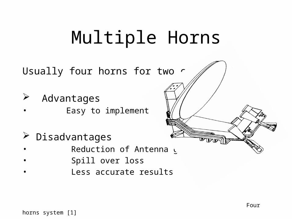
Multiple Horns
Usually four horns for two coordinates
Advantages• Easy to implement
Disadvantages• Reduction of Antenna gain• Spill over loss• Less accurate results
Four horns system [1]

Multimode feeds
Usually single horn is used with more than one mode.
Disadvantages
• Very difficult to implement
Advantages• More Antenna gain• Less Spill over loss• Very accurate results
Corrugated horn[1]

WAVEGUIDES• Hollow metal pipes • Why not tranmission lines ?• Constructed from conductive material • May be rectangular, circular or elliptical
Types of waveguides[2]

MODES
Electric or magnetic field pattern in waveguides
The field arrangements of the various modes of operation are divided into following categories:
Transverse Electric (TE): No electric field in direction of propagation of energy Transverse Magnetic (TM): No magnetic field in direction of propagation of energy Transverse electromagnetic modes (TEM) : No electric or magnetic field in direction of propagation of energy Hybrid modes : Have electric and magnetic fields in direction of propagation

TE mode and TM mode field pattern[3]

MODES OF OPERATION The number of modes depend on
• Frequency
• Size of waveguide
Dominant mode or principal mode
Have lowest cutoff frequency
Cutoff frequency

MODES OF OPERATION Since there are several TE and TM modes, subscripts are used
to complete the description of the field pattern.
In rectangular waveguides, the first subscript indicates the number of half-wave patterns in the “a” dimension, and the second subscript indicates the number of half-wave patterns in the “b” dimension.
TE10 TE20

HFSS PLOTS
TE20 E field plots of rectangular waveguides
TE10 E field plots of rectangular waveguide

HFSS PLOTS
TE11 E field plots of rectangular waveguide
TE10 E field plots of rectangular waveguide
Abstract
In this paper, by using of the antenna far field pattern of TE11 and TE21 modes, Monopulse tracking technique of TE21 mode is analyzed.
By using of these parameters, estimation error such as mean, variance and consequent root mean square error (RMSE) of TE21 mode tracking technique versus SNR are presented.
Introduction
In order to decrease production costs of the satellite, the designers pay attention to design LEO (Low Earth Orbit) satellites.
These satellites have a smaller size and lower weight than the satellites in higher orbits; as a result production and launching costs are less.
By using the LEO remote sensing satellites, pictures of the ground with the best quality are provided.

Problem:• Most significant problem of these satellites is
the requirement of tracking and consequently more complex data reception stations.
Proposed Solution:• In order to have more efficiency, the tracking
techniques of satellites were proposed . One of these techniques was multimode monopulse tracking technique.

One of the high order modes which are used at the LEO satellite ground stations is TE21. This mode has symmetrical radiation pattern with low side lobe levels.
Designers proposed TE21 as the best mode for tracking, along with TE11 as dominant mode. These modes has symmetrical radiation pattern with low side lobe levels.

The Radiation Patterns of TE11 and TE21 Modes
TE11 and TE21 modes are the sum and difference signal in a classic monopulse tracking technique, respectively.
The far field components of these modes in the spherical coordinate are:

Where J n (u) and kcn,1 a=τn,1 ′ are Bessel
functions and first zero of the derivative of the nth order of the first kind Bessel function, respectively. Also u= kasinθ and k = 2π /λ .
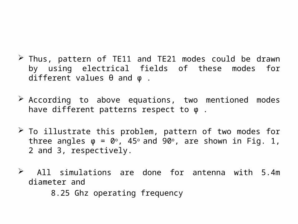
Thus, pattern of TE11 and TE21 modes could be drawn by using electrical fields of these modes for different values θ and φ .
According to above equations, two mentioned modes have different patterns respect to φ .
To illustrate this problem, pattern of two modes for three angles φ = 0o, 45o and 90o, are shown in Fig. 1, 2 and 3, respectively.
All simulations are done for antenna with 5.4m diameter and
8.25 Ghz operating frequency


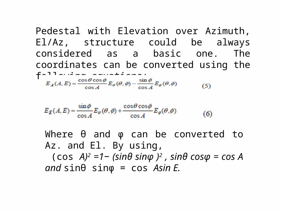
Pedestal with Elevation over Azimuth, El/Az, structure could be always considered as a basic one. The coordinates can be converted using the following equations:
Where θ and φ can be converted to Az. and El. By using, (cos A)2 =1− (sinθ sinφ )2 , sinθ cosφ = cos A and sinθ sinφ = cos Asin E.

Geometry of the structure of two coordinates on the antenna is shown in Fig4.

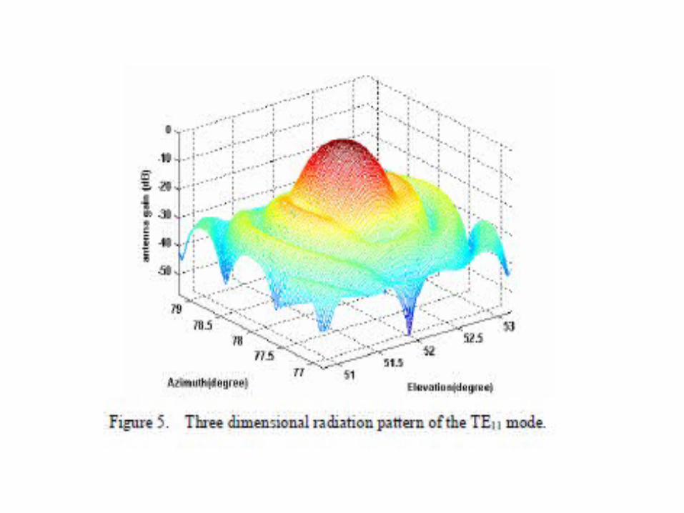
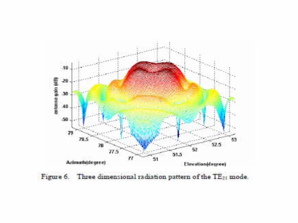
After conversion of the antenna pattern in spherical coordinate to El/Az pedestal coordinate, antenna pattern has a same sensitivity relative to deviation of the El. and Az.
According to above explanations, 3D pattern of two modes TE11 and TE21 for typical values Az= 78o and El= 52o are shown in Fig. 5 and 6, respectively.

Analysis of TE21 mode Linearity of error signal in convergence region Linear slope of errors in sum and difference pattern So value of error signal can be estimated by angle off set
Best angular offset of feed horns from antenna axis in four-horn monopulse technique is 0o =0b√2. [4] TE21 multimode monopulse uses single horn so deviation is single value
Figure-7 The comparison between deviation ofthe error signal in f four horn and multimode monopulse from linear function [5]

Analysis of TE21 mode Error signal in multimode is Ee = Ed / Es = kmm θ
Ed = Error in difference signal
Es = Error in sum signal
Ee = Overall error in monopulse tracking
θ = satellite angle’s offset relative to antenna axis θ2 = θaz
2 + θel2
Kmm = slope of error signal
where θt = 0 is the time in which the satellite is placed along to station antenna axis.

Analysis of TE21 mode
Figure-8 TE21 mode and error signal in multimode trackingtechnique.

Analysis of TE21 mode Usually slope value is computed over antenna axis (θt = 0).
In reality there is rate deviation in error signal
At θt = 0 , kmm = 1.0728 Deviation in error signal Slope value that is matched to error signal klmm = 1.1089 Slope of error signal kmm =1.0728
Deviation in error signal is calculated by statistical tools of estimation.
Figure-9 Linearity of the error signal in multimode tracking
technique.
COMPARISON OF ESTIMATION ERROR BETWEEN THEFOUR HORN AND MULTIMODE MONOPULSE TECHNIQUES
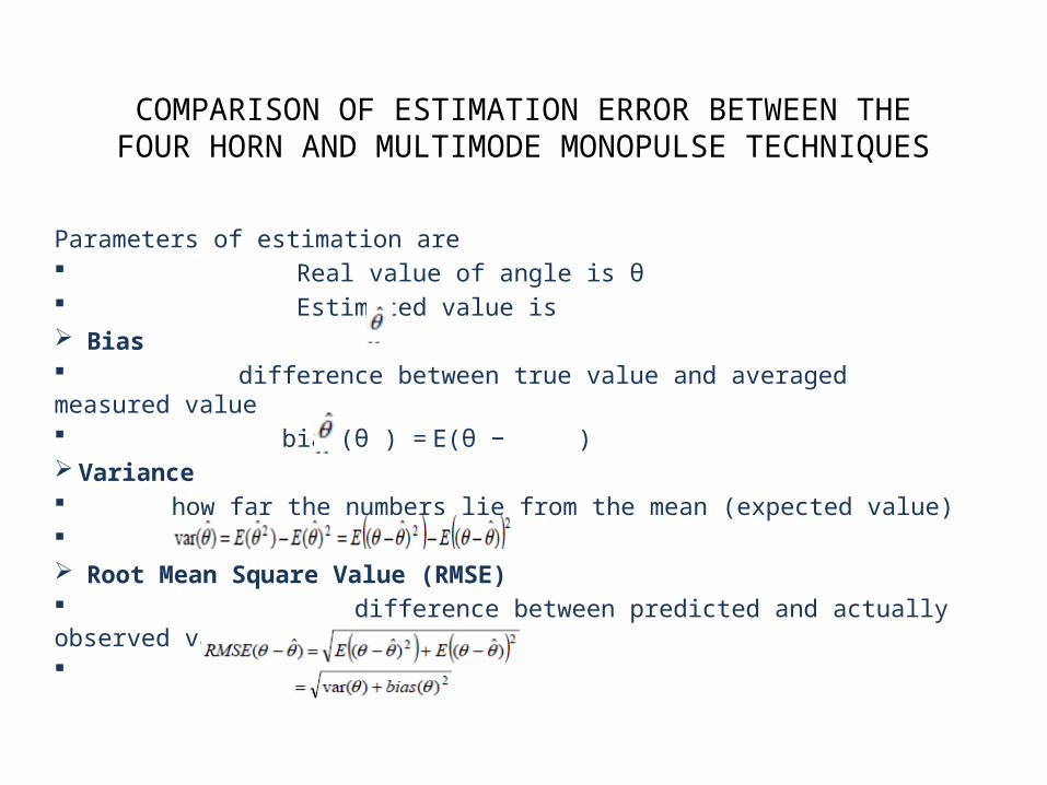
Parameters of estimation are Real value of angle is θ Estimated value is Bias difference between true value and averaged measured value bias(θ ) = E(θ − ) Variance how far the numbers lie from the mean (expected value) Root Mean Square Value (RMSE) difference between predicted and actually observed value
COMPARISON OF ESTIMATION ERROR BETWEEN THEFOUR HORN AND MULTIMODE MONOPULSE TECHNIQUES
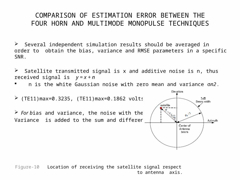
Several independent simulation results should be averaged in order to obtain the bias, variance and RMSE parameters in a specific SNR.
Satellite transmitted signal is x and additive noise is n, thus received signal is y = x + n n is the white Gaussian noise with zero mean and variance σn2 .
(TE11)max=0.3235, (TE11)max=0.1862 volts.
For bias and variance, the noise with the calculated Variance is added to the sum and difference signals.
Figure-10 Location of receiving the satellite signal respect to antenna axis.

Conclusion Error signal in TE21 multimode monopulse satisfies linearity property
Bias of the TE21 multimode monopulse has less variations than variance versus SNR.
fig--11 Bias of estimation error in multimode monopulse . Fig—12 Variance of estimation error in multimode monopulse
using kmm using k mm
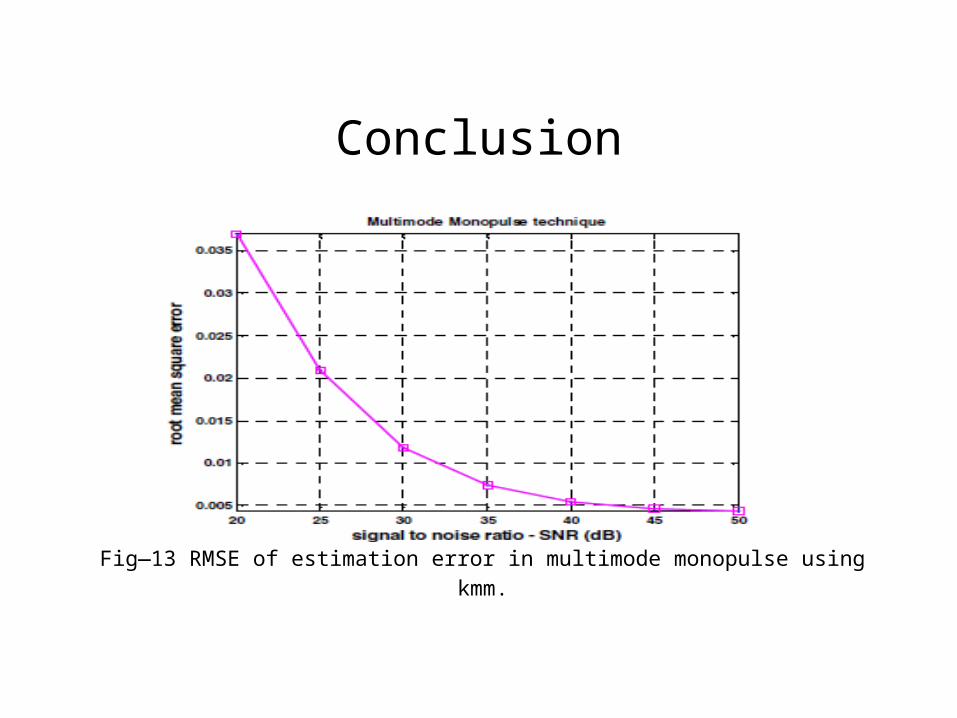
Conclusion
Fig—13 RMSE of estimation error in multimode monopulse usingkmm.

References [1]--- www.cst.com
[2]--- http://electriciantraining.tpub.com/14183/css/14183_15.html
[3]--- http://www.allaboutcircuits.com/vol_2/chpt_14/8.html
[4]--- L. Mohammady and G. R. Solat "Analysis of the Four-horn Monopulse in Tracking LEO Remote Sensing Satellites using Exact Model", IEEE ICACT Proc, pp. 1349-1352,2009.
[5]--- L. Mohammady and G. R. Solat The Comparison between the TE2l Mode and the Four-Hom Monopulse Technique for LEO Satellite Tracking , IEEE proceeding , pp 403-406 , 1st April 2010.

The End