montagevejledning instruction manual jumbo … · 4. components the jumbo tower scaffold can easily...
TRANSCRIPT

Montagevejledning
INSTRUCTION MANUALJUMBO TOWER SCAFFOLD
JUMBOJUMBOJUMBO®
WWW.JUMBO.AS
1. Conditions / Disclaimer2. Warranty3. Use & Function4. Components5. General Rules & Instructions for Use6. Assembly
6.1 Castor Section6.2 Middle Section6.3 Working Platform6.4 Outriggers6.5 Disassembly6.6 Diagrammes for Ballast & Outriggers
7. Assembly Platforms8. Mounting Guardrail9. Maintenance10. Spareparts11. Warnings & Misuse12. Distributor
Thank you for choosing a JUMBO pro-duct. We are confident that the scaffold will be of good use to you in future, and we look forward to advising you on other scaffold solutions.
Before using the rolling scaffold, it is very important that these instructions be read carefully. It is our aim to secure the highest possible safety in assembling and using the scaffold.
Last edit: September 2016
Registration No. 44 312 06 342304 -001
Scaffold Class III Max Load: 200 kg/m2
Instruction Manual EN 1298-IM-UK

W W W. J U M B O . A S
1. Conditions / DisclamerJUMBO Stillads A/S does not assume or undertake any responsibility for the content of this booklet or for the application of the booklet’s content in any way not described in this booklet.
JUMBO Stillads A/S cannot be held responsible for errors in the assembly instructions or for direct orindirect losses caused by delivery, presentation or the use of the contents of this booklet.
The contents may not in parts or in total be photocopied, reproduced or translated, without writtenpermission from JUMBO Stillads A/S.
2. WarrantyJUMBO Stillads A/S does not accept liability for any wear or fractures and tear on the scaffold partscaused by violation or wrong use. The guarantee does not apply for normal wear on the parts.
Should any scaffold not recommended by JUMBO Stillads A/S be fitted to the JUMBO TowerScaffold, the guarantee as well as any responsibility for any arisen consequences is renounced byJUMBO Stillads A/S
3. Use & FunctionJUMBO Tower Scaffold is constructed for a max. load of 200 kg pr. m².
We recommend the tower scaffold for safe and easy jobs at a given height. The folding scaffold isweatherproof and can be used both indoors and outdoors. In general, aluminium scaffolds should avo-id contact with untreated iron constructions and iron particles, as these are able to penetratethe aluminium.
When working outdoors, the scaffold should never be used at a wind force exceeding 12,5 m per second. In order to secure the scaffold from being blown over and when the scaffold is not in use, it is recommended to move it to a sheltered place.
The scaffolds are available in the lengths 178, 250 and 305 cm and in widths 74 and 130 cm.This manual applies to these lengths and widths.
JUMBO Tower Scaffold is composed of a few modules, that are easily build together in various combinations.Every part has been developed after years of know how and experience, making the assembly of the scaffold easy and safe to work with.
The platforms are secure by means of a storm lock (A).
The brakes on the castors are activated with a slight touch of the footbrake. (B)
All horizontal and diagonal braces are fitted with self-locking claws(C).
MAX. 200 kg/m2
AB
C
!

W W W. J U M B O . A S
4. Components
The JUMBO Tower Scaffold can easily be extended in height when needed. Please request a catalogue from your local dealer og directly at JUMBO.
If in doubt about which scaffold solution you need – please call us at 0045 7550 5075.
Working PlatformHorizontal braceHorizontal braceGuardrail frameToe board fittingToe boardPlatform with hatchPlatform without hatch
Castor Section2 m frame with rungsDiagonal braceHorizontal braceCastors

W W W. J U M B O . A S
!
5. General Rules and Instructions for Use
5.6 The JUMBO Tower Scaffold must always be erected on a secure and firm base that is able to sustain the weight of the scaffold and the load applied during work. When moving the scaffold push in the longitudinal direction only – and push by the base section only. Move it at walking speed and at a max. inclination of 2%. ONLY move the scafold by hand. Jolts must be avoided. Scaffolds mounted with wall cramps should only be moved parralel to the wall.
5.7 When moving the scaffold make sure no persons or loose items are on the scaffold
5.8 After moving the scaffold, the brakes must be engaged at once. Please ensure that all cas-tors are securely locked before getting onto the scaffold. Before entering or leaving the scaf-fold always take precautions against accidental rolling of the scaffold.
5.9 Beware of overhead obstructions. The scaffold should always be kept at least 3 m from en-ergized electric power lines.
5.10 Lifting devices or hoists must not be used on the scaffold.
5.11 Only climb the scaffold from inside. Ascending and descending the scaffold must only take place by the designated access. When using more than one platform, hatches must be stag-gered and kept closed at all times.
5.1 Be sure to follow the instructions for assembly and disassembly. The scaffoldshould always be assembled in level and plumb. Only fully qualified personswith the necessary knowledge of assembly and use should operate thescaffold.
5.2 Before assembly, all components should be checked. Only original, undama-ged JUMBO components should be used.
5.3 The castors should be mounted inside the vertical tubes of the frames. Make sure the castors are correctly mounted and fastened. The applied load of the scaffold must be evenly distributed over all 4 castors at all times. Use the spind-le to correct the height of scaffold and make it level.
5.4 Only use original JUMBO Ballast blocks. DO NOT use any kind of containers o, sandfilled buckets or any other contrap-tion.
5.5 Always secure the frames with clips. The curved part of the clip should pint outwards and downwards. Stick the straight part th-rough the holes in the frames and let the clip drop - and thus lock.
W W W. J U M B O . A S
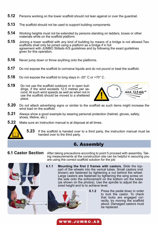
5.12 Persons working on the tower scaffold should not lean against or over the guardrail.
5.13 The scaffold should not be used to support building components.
5.14 Working heights must not be extended by persons standing on ladders, boxes or othermaterials while on the scaffold platform.
5.15 Joining a tower scaffold with any kind of building by means of a bridge is not allowed.Two scaffolds shall only be joined using a platform as a bridge if in fullagreement with JUMBO Stillads A/S guidelines and by following the exact guidelinesgiven for this operation.
5.16 Never jump down or throw anything onto the platforms.
5.17 Do not expose the scaffold to corrosive liquids and do not pound or beat the scaffold.
5.18 Do not expose the scaffold to long stays in -20° C or +70° C.
5.23 If the scaffold is handed over to a third party, the instruction manual must be handed over to the third party.
5.19 Do not use the scaffold outdoors or in open buil-dings, if the wind exceeds 12.5 metres per se-cond. At such wind speeds as well as when not in use the scaffold should be moved to a sheltered place.
5.20 Do not attach advertising signs or similar to the scaffold as such items might increase the wind load on the scaffold.
5.21 Always show a good example by wearing personal protection (helmet, gloves, safety,shoes, lifeline, etc.)
5.22 Make sure an instruction manual is at disposal at all times.
6. Assembly
6.1 Castor Section After taking precautions according to point 5 proceed with assembly. Tak-ing measurements at the construction site can be helpful in securing you are using the correct scaffold solution for the job
6.1.1 Mounting the first 2 frames with castors. Slide the top-part of the wheels into the verical tubes. Small castors (not shown) are fastened by tightening a nut behind the wheel. Large castors are fastened by tightening the wing screw on the side onto the enforcement on the bottom om the tubes (as shown on the photos). Use the spindle to adjust the de-sired height and to to achieve level.
6.1.2 Press the pedal down in order to lock the castor. To check that locks are engaged cor-rectly, try moving the scaffold about. Damaged castors must be replaced.
!

W W W. J U M B O . A S
6.1.3 Mount horizontal bracesErect the frames and connect them with 2 horizontal brac-es - 1 at each side.Mount the braces above the lowest rung - and mount them on the vertical tube from the inside out.
Make sure that the self-locking mechanism of the claw is activated.
6.1.4 Mounting diagonal bracesWith the two bottom frames connected and standing erect mount at diagonal bra-ce from the bottom rung on on side to the top rung on the other side.Always mount rungs after the following rules:
6.1.5 Tower scaffold should always be mounted with 2 diagonal braces pr. 2 metres height.
The diagonal braces can be mounted on the same side on the frames - or one on either side across from each other.
6.1.6 Ensure that the scaffold is at level and plumb.Use the spindles on the castors to adjust. Do not forget to tighten the wing screws after adjusting.
If ballast is needed (according to point 6.6) it should be placed on the scaffold now..
6.1.7 Mounting the first platform. The platform is to be hooked onto the steps of the frames. Slide the storm lock in place under the rung
IMPORTANT: Before continuing the assem-bly mount toe boards on the current plat-form according to point 6.3.3

W W W. J U M B O . A S
6.2 Middle Section
6.2.1 Mount frames onto the lower fra-mes.
Secure the frames with clips
6.2.2 Mount horizontal braces.When used as guardrail the horizontalt braces should be mounted at heights 50 cm and 100 cm measured from the platform. Mount the brace above a rung and from the inside out on the vertical tube
Take caution that selflocking claw on the braces is locked correctly
6.2.3 Mount diagonal braces.After mounting frames and horizontal bra-ces, moun diagonal braces after the follo-wing rules:
6.2.4 Always fit the scaffold with 2 diagonal braces pr. 2 etrers height. The diagonal braces can be mounted on the same side on the frames - or one on either side across from each other.
Take care that the claws are locke correctly!
6.2.5 Mounting further platforms.Mount the next platform at at max. distance of 8 rungs from the previous platformahmen max. Plat-forms with hatch should be mounted staggered.
Use the storm lock to secure the platform.
6.2.6 Horizontal braces.If you wish to leave out platform in the middle section you need to support the scaffold with horizontal braces. If this is the case, mount 2 horizontal braces 2 metres above the platform - one on each side. Mount the braces above a rung on the vertical tube.
After supporting the scaffold with horizontal braces the next platform can be mounted at a distance of max. 8 rungs measured from the horizontal bracing.

W W W. J U M B O . A S
6.4 Outriggers
6.3 Working Platform
6.3.1 Mount guardrail frames.The guardrail frames are mounted onto the side frames.
Secure with clips.
6.3.2 Mount horizontal braces.Horizontal braces are mounted as guardrail 50 und 100 cm above the platform. Mount them above rungs on the vertical tubes - from the indisde and out
Make sure the selflocking claws are locked correctly
6.3.3 Mount toe boards.First mount the toe board fittings on the vertical tubes of the frames. The fittings are easily fitted on the tubes right above the platform. Slinde the toe boards in place.Always mount the toeboard fittings and toe boards before mounting the next frames - this will lock the toe boards into place.
Toe boards (height 15 cm, width 3,2 cm) are mandatory on all sides of the platform
IMPORTANT: Keep platform hatches closed when not in use. The safety string should be kept in good condition.
6.4.1 Mounting outriggersMount JUMBO Tower Scaffold with ou-triggers according to the diagrammes under point 6.6).
Initially only fastend the couplers of the ourigger loosely on the scaffolds verti-val tube. Adjust the outrigger until the rubber foot is resting securely on the ground and the correct angle (45°) is achieved. Then tighten both couplers.
6.5 DisassemblyThe JUMBO folding scaffold is to be disassembled in reverse order of the assembling. Use plat-forms and guardrails in the middle section of the scaffold to ensure secure disassembly.Do not under any circumstances drop or throw any scaffolds components.
Keep castors locked during disassembly. Do not throw any scaffold parts onto the ground.
During transport, avoid excess jolts that could cause deformation of the tube profile
W W W. J U M B O . A S
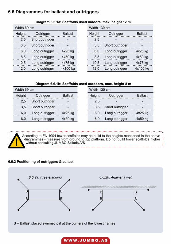
Diagram 6.6.1a: Scaffolds used indoors, max. height 12 mWidth 69 cm Width 130 cm
Height Outrigger Ballast Height Outrigger Ballast
2,5 Short outrigger - 2,5 - -
3,5 Short outrigger - 3,5 Short outrigger -
6,0 Long outrigger 4x25 kg 6,0 Long outrigger 4x25 kg
8,5 Long outrigger 4x50 kg 8,5 Long outrigger 4x50 kg
10,5 Long outrigger 4x75 kg 10,5 Long outrigger 4x75 kg
12,0 Long outrigger 4x100 kg 12,0 Long outrigger 4x100 kg
Diagram 6.6.1b: Scaffolds used outdoors, max. height 8 mWidth 69 cm Width 130 cm
Height Outrigger Ballast Height Outrigger Ballast
2,5 Short outrigger - 2,5 - -
3,5 Short outrigger - 3,5 Short outrigger -
6,0 Long outrigger 4x25 kg 6,0 Long outrigger 4x25 kg
8,0 Long outrigger 4x50 kg 8,0 Long outrigger 4x50 kg
6.6 Diagrammes for ballast and outriggers
According to EN 1004 tower scaffolds may be build to the heights mentioned in the above diagrammes - measure from ground to top platform. Do not build tower scaffolds higher without consulting JUMBO Stillads A/S
B B
B B
B B
B B
6.6.2 Positioning of outriggers & ballast
6.6.2a: Free-standing 6.6.2b: Against a wall
B = Ballast placed symmetrical at the corners of the lowest frames
!

W W W. J U M B O . A S
7. Assembly & Mounting - With Assembly PlatformThis section guides you through the installation of tower scaffolds with platform layers every 4 meters, using assembly platform(s) during assembly and dismantling.
7.1.1 Mounting the first set of assembly platforms.Mount a horizontal brace at 2 m height. (8th rung from the bottom) and place a platform on that same rung to the opposite side.
Place a platform at 1 m height (4th rung from the bottom) to the opposite side of the platform at 2 m, they will now be on opposite sides of the scaffold. Remember to ensure the plat-forms with the storm lock under each platform.Note: If you are building the scaffold to a height where outriggers are required (see table pt. 6.6) these must be mounted now, see pt. 6.4.
7.1.2 Further assembly
Mount the next frames from the assembly platform at 1m height. Push them down onto the spigots of the bottom frame. Remember to lock with the provided safety clips. Next, mount horizontal braces (see pt. 6.2.3 - 6.2.4)
7.1 Mounting with assembly platformStart by mounting the castor section described in pt. 6.1.1 – 6.1.6
Then mount the next assembly platform and the next horizontal brace 2 m higher up. Remember as-sembly platforms and horizontal braces must be offset. See Fig. 7a
Continue to mount assembly platforms and horizontal braces offset at a distance of 1 m height and mount frames and diagonals, until the desired height is reached. (Never mount higher than 2 m above the platform you stand on.
W W W. J U M B O . A S
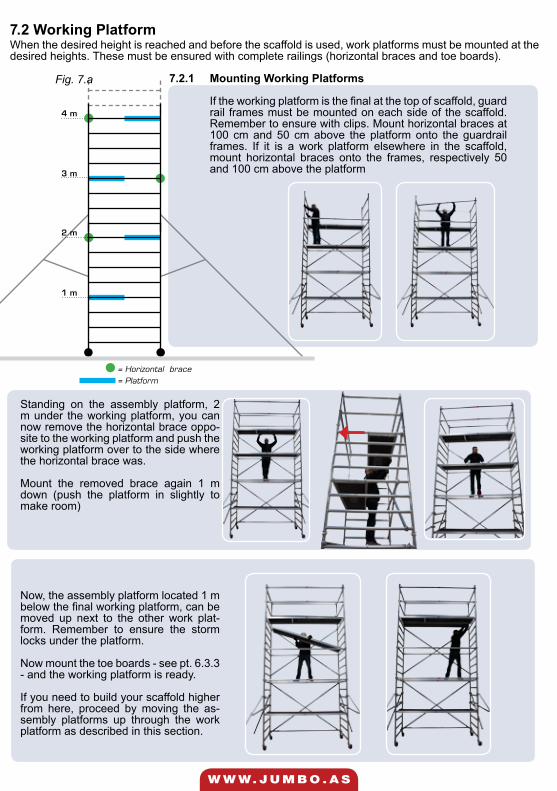
1 m
2 m
3 m
= Horizontal brace= Platform
4 m
7.2.1 Mounting Working Platforms
If the working platform is the final at the top of scaffold, guard rail frames must be mounted on each side of the scaffold. Remember to ensure with clips. Mount horizontal braces at 100 cm and 50 cm above the platform onto the guardrail frames. If it is a work platform elsewhere in the scaffold, mount horizontal braces onto the frames, respectively 50 and 100 cm above the platform
7.2 Working PlatformWhen the desired height is reached and before the scaffold is used, work platforms must be mounted at the desired heights. These must be ensured with complete railings (horizontal braces and toe boards).
Fig. 7.a
Standing on the assembly platform, 2 m under the working platform, you can now remove the horizontal brace oppo-site to the working platform and push the working platform over to the side where the horizontal brace was.
Mount the removed brace again 1 m down (push the platform in slightly to make room)
Now, the assembly platform located 1 m below the final working platform, can be moved up next to the other work plat-form. Remember to ensure the storm locks under the platform.
Now mount the toe boards - see pt. 6.3.3 - and the working platform is ready.
If you need to build your scaffold higher from here, proceed by moving the as-sembly platforms up through the work platform as described in this section.

W W W. J U M B O . A S
8. Mounting Guardrail
8.1 Fitting the mounting guardrail
The mounting guardrail must be mounted before accessing the platform. The guardrail must be fixed to the vertical tube one step below the desired platform height. The couplers must be fixed around the tube on both sides right above the step.
Repeat the same fitting on the other side of the scaffold.
8.2 Horizontal bracesWhen the mounting guardrail is mounted, access to the platform is safe. Further installation of hori-zontal braces and mounting of the scaffold can be continued in accor-dance with section 6.1.7 - 6.3.3
After mounting the horizontal bra-ces above the platform, the moun-ting guardrail can be removed.
8.3 Further mountingWhen the platform is equipped with complete guardrails, the mounting guardrail can be removed and re-installed on the next platform on the scaffold. The mounting guardrail must be fixed one step below the desired platform height - the couplers right above the step. Continue further mounting of the scaffold in accordance with section 8.1 - 8.3 and 6.2.3 - 6.3.3 until the desired height of the scaffold is reached.
The platform can be mounted before or after mounting of the mounting guardrail.
DO NOT access the platform before mounting guardrails are safely mounted on both sides!
A mounting guardrail (foldable), can be used as an extra precaution.
9. Maintenance
The maintenance of the tower scaffold is limited to control and replacement of the various modul-es of the tower scaffold.
Please use no hammer or the like to free the scaf-fold from mortar etc.
DO NOT use oil products to lubricate claws, storm locks and castors.

W W W. J U M B O . A S
Fig. 1
Fig. 2
Fig. 4
Fig. 5
Fig. 6
Fig. 8
Fig. 3
Fig. 7
Art no. Fig. Article Weight kg.
1001780 1 Platform without hatch 178 cm 10,5
1002500 1 Platform without hatch 250 cm 15,7
1003050 1 Platform without hatch 305 cm 21,0
1001781 2 Platform with hatch 178 cm 11,0
1002501 2 Platform with hatch 250 cm 16,1
1003051 2 Platform with hatch 305 cm 21,5
1450250 3 Ballast Block 25,0
1600100 4 Clip 0,1
1400200 5 Castor, adjustable 5,0
1500500 6 Base plate adjustable 34,1
FLB-1 7 Toeboard fitting 0,1
1610178 8 Toe board 178 cm 3,8
1610250 8 Toe board 250 cm 4,8
1610305 8 Toe board 305 cm 5,8
1610130 8 Toe board long 3,0
1610074 8 Toe board short 2,5
10. Spareparts

W W W. J U M B O . A S
Fig. 9
Fig. 11
Fig. 13
Fig. 15
Fig. 16Fig. 14
Fig. 12
Fig. 10
Art. no. Fig. Article Weight kg.
12135101 9 Guardrail frame, 2 rungs, 135 x 100 cm 3,7
12074101 10 Guardrail frame, 2 rungs, 74 x 100 cm 3,7
12135050 11 Frame, 2 rungs, 135 x 50 cm 3,2
12074050 12 Frame, 2 rungs, 74 x 50 cm 2,3
12135100 13 Frame, 4 rungs, 135 x 100 cm 6,8
12074100 14 Frame, 4 rungs, 74 x 100 cm 4,2
12135200 15 Frame, 8 rungs, 135 x 200 cm 11,5
12074200 16 Frame, 8 rungs, 74 x 200 cm 8,0
1101780 17 Horizontal brace 178 cm 2,5
1101784 17 Diagonal brace, 4-step for 178 cm 2,7
1101787 17 Diagonal brace, 7-step for 178 cm 3,0
1102500 17 Horizontal brace 250 cm 3,1

W W W. J U M B O . A S
Fig. 18
Art. no. Fig. Article Weight kg.
1102504 17 Diagonal brace, 4-step for 250 cm 3,2
1102507 17 Diagonal brace, 7-step for 250 cm 3,5
1103050 17 Horizontal brace 305 cm 3,6
1103054 17 Diagonal brace, 4-step for 305 cm 3,8
1103057 17 Diagonal brace, 7-step for 305 cm 4,0
1103510 17 Diagonal brace for 305 cm 4,0
1300170 18 Beam 178 cm 6,0
1300250 18 Beam 250 cm 7,0
1300305 18 Beam 305 cm 9,0
1300351 18 Beam 351 cm 10,0
1410150u 19 Short outrigger 4,0
1410250u 19 Long outrigger 5,0
Fig. 18
Fig. 17
Fig. 19
WWW.JUMBO.AS
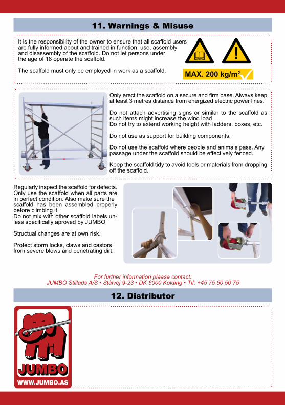
12. Distributor
11. Warnings & Misuse
It is the responsibility of the owner to ensure that all scaffold usersare fully informed about and trained in function, use, assembly and disassembly of the scaffold. Do not let persons under the age of 18 operate the scaffold.
The scaffold must only be employed in work as a scaffold.
Only erect the scaffold on a secure and firm base. Always keep at least 3 metres distance from energized electric power lines.
Do not attach advertising signs or similar to the scaffold as such items might increase the wind loadDo not try to extend working height with ladders, boxes, etc.
Do not use as support for building components.
Do not use the scaffold where people and animals pass. Anypassage under the scaffold should be effectively fenced.
Keep the scaffold tidy to avoid tools or materials from dropping off the scaffold.
Regularly inspect the scaffold for defects. Only use the scaffold when all parts are in perfect condition. Also make sure thescaffold has been assembled properly before climbing it.Do not mix with other scaffold labels un-less specifically aproved by JUMBO
Structual changes are at own risk.
Protect storm locks, claws and castorsfrom severe blows and penetrating dirt.
For further information please contact: JUMBO Stillads A/S • Stålvej 9-23 • DK 6000 Kolding • Tlf: +45 75 50 50 75
JUMBOJUMBOJUMBO®
WWW.JUMBO.AS
!MAX. 200 kg/m2