montana canvas tent structure design - digital commons
TRANSCRIPT

Montana Tech LibraryDigital Commons @ Montana TechProceedings of the Annual Montana Tech Electricaland General Engineering Symposium Student Scholarship
2016
Montana Canvas Tent Structure DesignEric SchowengerdtMontana Tech of the University of Montana
Nick MoralesMontana Tech of the University of Montana
Follow this and additional works at: http://digitalcommons.mtech.edu/engr-symposium
This Article is brought to you for free and open access by the Student Scholarship at Digital Commons @ Montana Tech. It has been accepted forinclusion in Proceedings of the Annual Montana Tech Electrical and General Engineering Symposium by an authorized administrator of DigitalCommons @ Montana Tech. For more information, please contact [email protected].
Recommended CitationSchowengerdt, Eric and Morales, Nick, "Montana Canvas Tent Structure Design" (2016). Proceedings of the Annual Montana TechElectrical and General Engineering Symposium. 9.http://digitalcommons.mtech.edu/engr-symposium/9

MONTANA CANVAS TENT
STRUCTURE DESIGN
Eric Schowengerdt & Nick Morales

Montana Canvas Tent Structure Design
1
Abstract
Montana Canvas is one of the premier tent building companies in the world. Their product line
includes backcountry tents, wall tents, and large scale shipping tarps. Currently they are looking
to expand their product line to include large party tents of up to 60’ in width. Eric Schowengerdt
and Nick Morales, both Mechanical Engineering students at Montana Tech, have both designed
fixtures and verified several of the fixtures already in use by Montana Canvas. These fixtures
were put through finite element analysis on a computer and many static hand calculations, which
simulated the loading on them from 120 mph to 85 mph wind conditions. This report will outline
the processes used to determine the max loading area, alternative solutions to the structure, and
finite element analysis on the structure.

Montana Canvas Tent Structure Design
2
Contents Abstract ......................................................................................................................................................... 1
Introduction .................................................................................................................................................. 3
Wind Load Analysis ....................................................................................................................................... 3
Application of Load Analysis ......................................................................................................................... 7
Currently Produced Parts ............................................................................................................................ 11
Project Status .............................................................................................................................................. 12
Conclusion ................................................................................................................................................... 12
References .................................................................................................................................................. 14
Appendix A .................................................................................................................................................. 15

Montana Canvas Tent Structure Design
3
Introduction
Montana Canvas is a company located in Belgrade Montana that specializes in wall tents and cargo
tarps. They recently decided to expand their business to include manufacture of large scale tents for
large outdoor events. Fixtures were made by a Spokane Washington machine shop to make a tent that
was 30 feet wide by 30 feet long; to expand their business they wanted to know if these fixtures could
be used in larger size tents. The sizes they wanted to expand to were (40X80, 50X100, and 60X120) feet.
To determine if these fixture are suitable for these different tent sizes, the project has been broken into
two parts.
The scope of the first part of this project is to understand wind loads and how the topography can affect
the velocity of the wind. These factors come from ASCE (American Society of Civil Engineers) book. In
this document, wind loads can be transformed into pressures based off of the different zones of the
structure. These pressures are determined from the location, occupancy, and exposure to the elements
of the tent.
The scope of the second part was being able to apply these loads to the tent structure. With the
structure built in SolidWorks, wind loads, setup loads, and snow loads can be applied to perform an
overall structural finite element analysis. However issues arose from using SolidWorks, and the infinite
analysis had to be hand calculated. It was determined that the aluminum poles for the roof structure in
sections B and E of the wind analysis were the weak link in the structure. This analysis was applied to a
40’X80’ tent structure and will be integral in determining how to size each of the parts of the frame to
handle this worst case scenario. From this worst case scenario of 85 mph, the data can then be applied
to larger tents as needed by the company.
Wind Load Analysis
We were able to calculate winds loads by summing internal and external pressures applied to horizontal
and vertical projections of the tent structure. The main equation that defined this is:
𝑷𝒔 = 𝝀𝑰𝑲𝒛𝒕𝑷𝒔𝟑𝟎
This equation comes from the ASCE (American Society of Civil Engineers) book of codes under chapter
28 page 244 (Wind Loads on Buildings). Each variable of the equation is defined below.
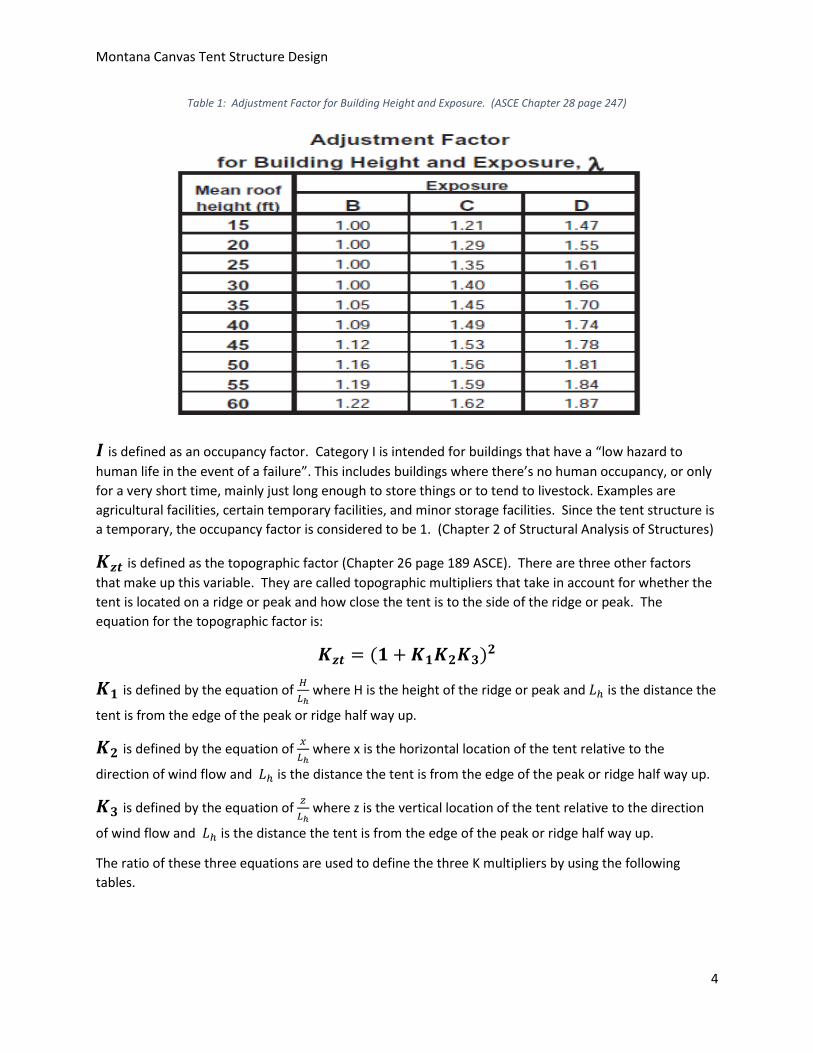
λ is defined as the adjustment factor for building height and exposure (Chapter 26 page 190). To be
conservative with the tent structure, exposure C was selected. Exposure C is defined as a structure site
that is in open terrain with scattered obstructions having heights generally less than 30 feet (Chapter 26
page 195). The adjustment factor can then be determined with the mean roof height of the tent
structure and the table below.
Montana Canvas Tent Structure Design
4
Table 1: Adjustment Factor for Building Height and Exposure. (ASCE Chapter 28 page 247)
𝑰 is defined as an occupancy factor. Category I is intended for buildings that have a “low hazard to
human life in the event of a failure”. This includes buildings where there’s no human occupancy, or only
for a very short time, mainly just long enough to store things or to tend to livestock. Examples are
agricultural facilities, certain temporary facilities, and minor storage facilities. Since the tent structure is
a temporary, the occupancy factor is considered to be 1. (Chapter 2 of Structural Analysis of Structures)
𝑲𝒛𝒕 is defined as the topographic factor (Chapter 26 page 189 ASCE). There are three other factors
that make up this variable. They are called topographic multipliers that take in account for whether the
tent is located on a ridge or peak and how close the tent is to the side of the ridge or peak. The
equation for the topographic factor is:
𝑲𝒛𝒕 = (𝟏 + 𝑲𝟏𝑲𝟐𝑲𝟑)𝟐
𝑲𝟏 is defined by the equation of 𝐻
𝐿ℎ where H is the height of the ridge or peak and 𝐿ℎ is the distance the
tent is from the edge of the peak or ridge half way up.
𝑲𝟐 is defined by the equation of 𝑥
𝐿ℎ where x is the horizontal location of the tent relative to the
direction of wind flow and 𝐿ℎ is the distance the tent is from the edge of the peak or ridge half way up.
𝑲𝟑 is defined by the equation of 𝑧
𝐿ℎ where z is the vertical location of the tent relative to the direction
of wind flow and 𝐿ℎ is the distance the tent is from the edge of the peak or ridge half way up.
The ratio of these three equations are used to define the three K multipliers by using the following
tables.

Montana Canvas Tent Structure Design
5
Table 2: K multiplier tables for the topographic factor. (ASCE Chapter 26 page 196)
In all three multipliers, worst case scenarios were assumed to compensate for many different locations
that the tent structure could be assembled at.
𝑷𝒔𝟑𝟎 is defined by the tent structure being broken down into zones A-H. The area of each zone is then
calculated as if the wind is blowing on the side and front of the structure. The figure below shows the
structure and how the zones are developed.

Montana Canvas Tent Structure Design
6
Figure 1: Example of the tent being zoned out with the windward being on the side
Horizontal and vertical pressure were then interpolated from the table below for the different zones of
the structure. It was determined that a 60 foot wide by 120 foot long tent would have a roof angle of
21.14 degrees.

Montana Canvas Tent Structure Design
7
Table 3: Designed wind pressures for enclosed structures. (ASCE Chapter 28 page 246)
The worst case scenario of a 120 mph wind was used with the roof angle of 21.14 degrees to develop
wind pressures for each zone. The wind pressures were then multiplied by the area of each zone to
come up with the pressures of the structure.
Application of Load Analysis
Initially SolidWorks was used to perform an overall structural finite element analysis, since the fixtures
were already made in SolidWorks prior to the project. The aluminum tent poles were then created and
applied to the program to get an overall skeleton of a 40’X80’ tent. A picture of the tent structure can
be seen on the next page in figure two.

Montana Canvas Tent Structure Design
8
Figure 2: An example of the tent structure skeleton that was designed in SolidWorks.
Once the structure was completed, finite element analysis was applied to the structure, but we were
never able to get it to run correctly due to the complex files of the fixtures and size of the tent. This
process would cause the program to fail without any results.
Since SolidWorks could not give us the data we needed, we were forced to hand calculate the loads of
the tent by using method of sections for a truss system. The wind loads of each zone calculated from
above were applied to the structure. Then the moments were summed at the based pole on the left
hand side of the structure. With the moments summed at that point, the forces then could be summed
in the vertical direction to find the last missing force. This then completed our free body diagram of the
tent structure and provided the location of the largest load on the tent. This load was located from the
peak of the roof gable to the side vertical pole of the tent. The pole was determined to have a bending
stress of 391 kips per square inch at 120 mph. Since 6061 aluminum alloy has a yield strength of 16 kips
per square inch, it was determined that the tent would definitely fail at 120 mph winds. It was then
decided to try a smaller wind load calculation and or a different tent pole size. With an 85 mph wind
load the frame member would be receiving a force of 4323 pounds. The aluminum alloy still proved to
fail even with a larger diameter pole. We then decided that a single pole will not work with a tent
structure of 40’X80’ or larger.

Montana Canvas Tent Structure Design
9
We decided to look at various other tent structures and decided to try to apply the same calculations to
a structure that has a truss structure system instead of one pole. Figure three below shows a picture of
a truss structure that we have designed to allow a larger stress.
Figure 3: An example of a truss structure that would allow a larger force on a tent structure.
The 6061 aluminum alloy that was two inch diameter was then used in the truss structure illustrated
above. Calculations were then run again to see if the aluminum alloy applied in this manner could
handle the bending stress. We found that it could but at the expense of the distance in which the two
pipes were separated. We found that with the two inch diameter aluminum alloy had to be separated
at a distance of 24 inches to handle the force applied.
We then decided to work the calculations backwards from 16 kips per square inch, to the max wind load
that 6061 aluminum alloy poles could handle. This was determined by using the two equations below.
𝑃 =𝐹
𝐴 𝑥 𝐶𝑑
𝑉 = (𝑃
0.00256)
12
Where in equation one P is equal to pressure, F is equal to force, A is equal to area, and Cd is the drag
coefficient which was equal to 20. By plugging the found pressure in equation one into equation two,
the wind velocity can be found in mph. It was determined that with a two inch separation of the poles
that the max wind load that the aluminum 6061 alloy could withstand would be a 31 mph wind load.

Montana Canvas Tent Structure Design
10
Though this is a temporary structure and chances of having it set in a large wind load would be rare, we
wanted to be able to come up with a solution to having a tent withstand the parameters of an 85 mph
wind load. At this point since we were testing so many different scenarios, we decided to make an excel
sheet that we could just enter in the size of the tubes, the separation distance between the tubes, the
force perpendicular to the beam, and the length of the beam to come up with the bending stress. An
example of the program can be seen in Figure four on the next page with 301 stainless steel above and
6061 aluminum alloy below.
Figure 3: An example of an excel program to calculate the bending stress given the dimensions in the boxed areas.

Montana Canvas Tent Structure Design
11
The solution we came up with was to use a quarter inch hard 301 stainless steel with a two inch
diameter. As seen above in figure three this material could withstand a bending strength of 148 kips per
square inch with a separation of 4.5 inches. This type of material could also be scalable to larger tents
with such a larger yield strength.
Currently Produced Parts
The parts shown in the figures below are the ones currently produced by the machine shop in Spokane,
WA and will be evaluated in our analysis, along with other alternatives which we may or may not deem
more suitable. These parts are currently used in conjunction with standard aluminum alloy piping as the
long pieces of the structure, but can easily be used with the 301 stainless steel that is made with a two
inch outside diameter.
Figure 4: Slider, apex endcap with adjustable angle setting, and free-floating endcap.

Montana Canvas Tent Structure Design
12
Project Status
The project was going as planned until the application of SolidWorks. The fact that we could not run any
structural finite element analysis had set us back. This is due to having to hand calculate the forces on
the structure and understand where the weakest element would be. The wind pressures have been
determined for a 60’X120’, 30’X60’, and 40’X80’ tent. These calculations can be observed on the
attached excel spreadsheet for a 60’X120’ tent. We have found that a 40’X80’ tent would be able to
withstand 85 mph wind loads as long as the truss structure introduced above was applied. The 6061
aluminum alloy would work as long as there was a separation of 24 inches between the poles. The
better alternative would be to use the quarter inch harden 301 stainless steel which had a greater yield
strength and only had to be separated by 4.5 inches. There has been a total of 117 man hours dedicated
to this project so far. The hours and description of time have also been attached to this report and can
be observed in the attached excel spreadsheets.
The next step for this project is to apply these forces from the truss structure to the fixtures in
SolidWorks. We started to apply these loads to the fixtures but still have come across the same problem
as stated above. The SolidWorks program crashes when the analysis is applied. This could be due to the
outdated computers that Montana Tech has. The fixtures still have not been verified to handle the
loads calculated with the tent poles above. The plan in the future would be for the next senior design
group to be able to apply these loads in SolidWorks and get some reasonable data with new computers.
Conclusion
Originally the scope of this project entailed the structural analysis of the supplied fixtures and how they
can be applied to larger tents of 40’X80’, 50’X100’, and 60’X120’. The wind loads of the various size
tents where determined but could not be applied when using the SolidWorks program. We found the
program to crash when the finite structural analysis was applied to the various structures. This caused
us to hand calculate the loads for a 30’X60’ and 40’X80’ tent, which made unexpected delays in finishing
the project as outlined above. However because of the delay we were able to determine that the
weakest link in the tent structure was a roof tent pole made of 6061 aluminum alloy. This alloy only had
a yield strength of 16 kips per square inch and we had calculated the bending stress to be 56 kips per
square inch. It was determined that the roof structure had to be made into a truss structure to be able
to withstand the 85 mph wind loads.
An Excel program was made to quickly calculate the bending stress in a double tube truss beam when
the program is given the size of the tubes, the separation distance between the tubes, the force
perpendicular to the beam, and the length of the beam.
The aluminum, having a maximum allowable stress (based on yielding) of 16ksi, needed a separation
distance of 24 inches to sustain the wind load at 85mph. The ¼ hard 301 stainless steel performed much
better in this simulation, needing only 4.5 inches of separation distance in the beam. These calculations
show that the ¼ hard 301 stainless is the superior option for building these large tents. This excel

Montana Canvas Tent Structure Design
13
program can be used to further calculate what beam dimensions are needed for greater and lighter
loads, and was given to Montana Canvas.
There has been progress in this project, but not to the scope of which is stated above. There has been a
solution presented to the tent poles and making a truss structure, but there is still no analysis to the
fixtures. The bending stress calculated for the truss system has to be applied to the fixtures. Since the
fixtures are made of stainless steel, it can be assumed that they can withstand a larger load than the
6061 aluminum alloy poles. Best practice would be to run a finite structural analysis to the fixtures using
SolidWorks or by hand calculations.

Montana Canvas Tent Structure Design
14
References
Breyer, D. (2007). Chapter 2 Design loads. In Design of wood structures--ASD/LRFD (6th ed.).
New York: McGraw-Hill.
American Society of Civil Engineers (2013). Minimum Design Loads for Buildings and Other Structures. Published by American Society of Civil Engineers http://www.aksteel.com/pdf/markets_products/stainless/austenitic/301_Stainless_Steel_PDB_201512.pdf
Personal Weekly Advising meetings
Kukay, B. (2015, September 30). Weekly advising meetings [Personal interview].
Personal Weekly Advising meetings
Hunter, L. (16, January 16). Weekly advising meetings [Personal interview].

Montana Canvas Tent Structure Design
15
Appendix A
Contained in this appendix are the hours worked sheet, and the excel spreadsheet showing calculations
pertaining to the wind load analysis calculations

Montana Canvas Tent Structure Design
16

Montana Canvas Tent Structure Design
17
Montana Canvas Tent Structure Design
Weekly report
Eric Schowengerdt Nick Morales
Date 2/1/16
Last week we were tasked with designing a 30X60 tent structure in SolidWorks. The purpose of this was to apply wind loads to the structure as a whole to understand how the fixtures react. The main fixture we were focusing on was the gable fixture. The problem were are running into is that we are having
a hard time with making the canvas attach to the tent frame. We need this attachment because without it
there is no accurate place to apply the calculated wind loads. We also need to design the connection for the 15 foot horizontal members. We anticipate this to set us back one week.
Tasks completed:
30X60 tent structure in SolidWorks
Wind load calculations for a 30X60 structure
Date
Eric Hours
Nick Hours
1/26/16
2
2 1/28/16
2
2
2/1/16
2
2
Total hours 6
6
Goals for this week: Finish 30X60 structure with canvas
Make new horizontal member
Apply wind loads to structure
Analyze gable member

Montana Canvas Tent Structure Design
18
Montana Canvas Tent Structure Design
Weekly report
Eric Schowengerdt Nick Morales
Date 2/8/16
Last week we struggled to make the 30X60 structure in solid works with the tent canvas on it. It was suggested to make the exterior canvas a solid rigid plane. So we calculated the different wind zones and made individual planes to represent each wind zone on the tent. We have been able to merge the planes with the tent structure and started to apply loads. When trying to run the simulation we had many interferences. This could be due to the way the fixtures were made in Spokane. We used the stubby fixture to attach the horizontal cross members that were 15 feet long.
Tasks completed:
30X60 tent structure with outer canvas shell in SolidWorks
Corrected wind load calculations for a 30X60 structure
Date
Eric Hours
Nick Hours
1/26/16
2
2 1/28/16
2
2
2/1/16
2
2 2/2/16
1.5
1.5
2/4/16
2
2 2/8/16
2
2
Total hours 11.5
11.5
Goals for this week: Finish 30X60 structure with canvas
Make new horizontal member
Apply wind loads to structure
Analyze gable member

Montana Canvas Tent Structure Design
19
Montana Canvas Tent Structure Design
Weekly report
Eric Schowengerdt Nick Morales
Date 2/15/16
We still continue to struggle with running a load analysis on the tent structure. Last week scheduled a meeting with Steve Tarrant to see if he could point us in the right direction. We had submitted our program with him to look at it. He re mated the fixtures to make the geometry better. This solved the rebuild errors we got before but now we are getting mesh errors. Since the project won’t mesh we can’t run the simulation. We have sent off an email to SolidWorks to see if we can get some help. We are also going to schedule another meeting with Steve.
Tasks completed:
30X60 tent structure with outer canvas shell in SolidWorks
Corrected wind load calculations for a 30X60 structure
Finish 30X60 structure with canvas
Date
Eric Hours
Nick Hours
1/26/16
2
2 1/28/16
2
2
2/1/16
2
2 2/2/16
1.5
1.5
2/4/16
2
2 2/8/16
2
2
2/9/16
1
1 2/10/16
1
1
2/16/16
1
1
2/17/16
1
1 Met with Steve
2/18/16
1
1 2/22/16
2
3
Total hours 18.5
19.5

Montana Canvas Tent Structure Design
20
Goals for this week: Meet with Steve again
Analyze email from SolidWorks
Finish 30X60 structure with canvas
Make new horizontal member
Apply wind loads to structure
Analyze gable member

Montana Canvas Tent Structure Design
21
Montana Canvas Tent Structure Design
Weekly report
Eric Schowengerdt Nick Morales
Date 2/29/16
With the issues of running the analysis through SolidWorks, it was decided to try to make calculate
the forces in just the front structure. By doing this we could narrow down the pole with the most force on it and spec the tent structure to that. This was decided during our presentation on 2-29. With the loads we could also try to simplify the analysis on SolidWorks to just the pole or members. So far we have determined the forces on the front structure by summing the moments and forces in the y direction. We also developed a shear moment diagram to see which force is greater on that beam. Based off this information we were able to size the pipe that would be needed to make this basic structure work.
Tasks completed:
30X60 tent structure with outer canvas shell in SolidWorks
Corrected wind load calculations for a 30X60 structure
Finish 30X60 structure with canvas
Load calculations on front tent assembly
Shear/Moment diagram of pole with largest loads
Determined size of pipe for structure as is
Date
Eric Hours
Nick Hours
1/26/16
2
2 1/28/16
2
2
2/1/16
2
2 2/2/16
1.5
1.5
2/4/16
2
2 2/8/16
2
2
2/9/16
1
1 2/10/16
1
1
2/16/16
1
1
2/17/16
1
1 Met with Steve
2/18/16
1
1 2/22/16
2
3

Montana Canvas Tent Structure Design
22
2/24/16
2
2 2/28/16
3
3
2/29/16
2
2 Presentation on Status
3/3/16
1
1 3/7/16
2
2
Total hours 28.5
29.5
Goals for this week: To put hand calculations into excel
Apply loads to members in solid works
Run analysis in SolidWorks to compare hand calculations
Analyze gable member

Montana Canvas Tent Structure Design
23
Montana Canvas Tent Structure Design
Weekly report
Eric Schowengerdt Nick Morales
Date 3/7/16
It was determined that with a wind load of 120 mph, that the current structure could not handle this. So it was suggested to work backwards using a wind load of 80 mph to determine if the current structure could handle this. We have also researched other tent structure types and have found one that looks like a great idea. It has actual truss support opposed to just one pole. We have now started calculations to see if that could hold 120 mph wind load with the fixtures designed. We also decided to try to work it backwards to see what size pole can work with an 80 mph wind load.
Tasks completed:
30X60 tent structure with outer canvas shell in SolidWorks
Corrected wind load calculations for a 30X60 structure
Finish 30X60 structure with canvas
Load calculations on front tent assembly
Shear/Moment diagram of pole with largest loads
Determined size of pipe for structure as is
Found new structure to apply loads to
Determined loads calculated for current structure and 120mph wind
Date
Eric Hours
Nick Hours
1/26/16
2
2 1/28/16
2
2
2/1/16
2
2 2/2/16
1.5
1.5
2/4/16
2
2 2/8/16
2
2
2/9/16
1
1 2/10/16
1
1
2/16/16
1
1 2/17/16
1
1 Met with

Montana Canvas Tent Structure Design
24
Steve
2/18/16
1
1 2/22/16
2
3
2/24/16
2
2 2/28/16
3
3
2/29/16
2
2 Presentation on Status
3/3/16
1
1 3/7/16
2
2
3/9/16
3
3 3/21/16
2
2
Total hours 33.5
34.5
Goals for this week: To put hand calculations into excel
Apply loads to members in solid works
Run analysis in SolidWorks to compare hand calculations
Analyze gable member
Load calculations for new structure

Montana Canvas Tent Structure Design
25
Montana Canvas Tent Structure Design
Weekly report
Eric Schowengerdt Nick Morales
Date 3/21/16
We found that the 15.875 foot pole could not handle loads of 85mph alone. There will have to be support applied to the pole based off of our new structural design of the tent. This means making the poles into a truss form and adding another horizontal member. We will move forward by determining whether the new design can handle the new loads. We are still calculating a simple truss that can handle a 120mph wind load.
Tasks completed:
30X60 tent structure with outer canvas shell in SolidWorks
Corrected wind load calculations for a 30X60 structure
Finish 30X60 structure with canvas
Load calculations on front tent assembly
Shear/Moment diagram of pole with largest loads
Determined size of pipe for structure as is
Found new structure to apply loads to
Determined loads calculated for current new structure at 80mph wind
Date
Eric Hours
Nick Hours
1/26/16
2
2 1/28/16
2
2
2/1/16
2
2 2/2/16
1.5
1.5
2/4/16
2
2 2/8/16
2
2
2/9/16
1
1 2/10/16
1
1
2/16/16
1
1 2/17/16
1
1 Met with

Montana Canvas Tent Structure Design
26
Steve
2/18/16
1
1 2/22/16
2
3
2/24/16
2
2 2/28/16
3
3
2/29/16
2
2 Presentation on Status
3/3/16
1
1 3/7/16
2
2
3/9/16
3
3 3/21/16
2
2
3/21/16
2
2 3/23/16
1
1
3/28/16
2
2
Total hours 38.5
39.5
Goals for this week: To put hand calculations into excel
Load calculations for new structure

Montana Canvas Tent Structure Design
27
Montana Canvas Tent Structure Design
Weekly report
Eric Schowengerdt Nick Morales
Date 3/21/16
We started working on 40X80 tent. We calculated the bending stress at 85 mph. With the cross pieces the bending stress ended up being 55774 psi on a truss piece that is a one inch tube on top of a 3 inch tube and separated by 4 inches. We need to be at 32,000 or less for stainless steel because that is its yield strength. We worked the tubes backwards to get the max wind speed that the tent can handle.
Tasks completed:
30X60 tent structure with outer canvas shell in SolidWorks
Corrected wind load calculations for a 30X60 structure
Finish 30X60 structure with canvas
Load calculations on front tent assembly
Shear/Moment diagram of pole with largest loads
Determined size of pipe for structure as is
Found new structure to apply loads to
Determined loads calculated for current new structure at 80mph wind
Designed new truss structure for tent
Calculated yield strength of new truss section
Found psf for zone B=2.48 and zone E=3.93
Found yield strength of truss 32,000 psi
Found force with 85 mph of 40X80 tent to be 55,774 psi
Date
Eric Hours
Nick Hours
1/26/16
2
2 1/28/16
2
2
2/1/16
2
2 2/2/16
1.5
1.5
2/4/16
2
2 2/8/16
2
2

Montana Canvas Tent Structure Design
28
2/9/16
1
1 2/10/16
1
1
2/16/16
1
1
2/17/16
1
1 Met with Steve
2/18/16
1
1 2/22/16
2
3
2/24/16
2
2 2/28/16
3
3
2/29/16
2
2 Presentation on Status
3/3/16
1
1 3/7/16
2
2
3/9/16
3
3 3/21/16
2
2
3/21/16
2
2 3/23/16
1
1
3/28/16
2
2 3/29/16
1
1
3/31/16
4
4 4/4/16
1
1
Total hours 44.5
45.5

Montana Canvas Tent Structure Design
29
Montana Canvas Tent Structure Design
Weekly report
Eric Schowengerdt Nick Morales
Date 4/4/16
We started to calculate the truss with the same size tubing on top and bottom. We need to figure out the separation distance to make the truss work with a reasonable wind pressure. Once this is accomplished we will apply the forces to the fixtures in solid works. The next step will be looking at a 50X100 size tent and apply the same procedure, time permitting.
Tasks completed:
30X60 tent structure with outer canvas shell in SolidWorks
Corrected wind load calculations for a 30X60 structure
Finish 30X60 structure with canvas
Load calculations on front tent assembly
Shear/Moment diagram of pole with largest loads
Determined size of pipe for structure as is
Found new structure to apply loads to
Determined loads calculated for current new structure at 80mph wind
Designed new truss structure for tent
Calculated yield strength of new truss section
Found psf for zone B=2.48 and zone E=3.93
Found yield strength of truss 32,000 psi
Found force with 85 mph of 40X80 tent to be 55,774 psi
Determined the yield strength of the 2X2 inch tube truss
Researched possible metals that might work for truss

Montana Canvas Tent Structure Design
30
Date
Eric Hours
Nick Hours
1/26/16
2
2 1/28/16
2
2
2/1/16
2
2 2/2/16
1.5
1.5
2/4/16
2
2 2/8/16
2
2
2/9/16
1
1 2/10/16
1
1
2/16/16
1
1
2/17/16
1
1 Met with Steve
2/18/16
1
1 2/22/16
2
3
2/24/16
2
2 2/28/16
3
3
2/29/16
2
2 Presentation on Status
3/3/16
1
1 3/7/16
2
2
3/9/16
3
3 3/21/16
2
2
3/21/16
2
2 3/23/16
1
1
3/28/16
2
2 3/29/16
1
1
3/31/16
4
4 4/4/16
1
1
4/6/16
2
2 4/11/16
1
1
Total hours 47.5
48.5
Goals for this week: Determine the distance between the 2 two inch tubes for truss
Apply determined loads to the fixtures in SolidWorks
Work on Poster
Repeat for larger tent
Find alternative metal that would handle larger loads