montreal protocol the ozone layer
TRANSCRIPT

MONTREAL PROTOCOL
ON SUBSTANCES THAT DEPLETE
THE OZONE LAYER
1998 REPORT OF THESOLVENTS, COATINGS AND ADHESIVES
TECHNICAL OPTIONS COMMITTEE (STOC)
1998 Assessment

Montreal Protocolon Substances that Deplete the Ozone Layer
UNEP1998 REPORT OF THESOLVENTS, COATINGS AND ADHESIVESTECHNICAL OPTIONS COMMITTEE (STOC)
1998 ASSESSMENT
The text of this report is composed in Arial.
Co-ordination: Solvents, Coatings and AdhesivesTechnical Options Committee (STOC)
Composition: Mohinder Malik (Co-chair)
Layout: Angelika Pein / Birgit Hägele
Reproduction: UNEP Nairobi, Ozone Secretariat
Date: December, 1998
No copyright involvedPrinted in Kenya; 1998
ISBN 92-807-1732-4
1998 UNEP STOC Assessment Report - Page i

DISCLAIMER
The United Nations Environment Programme (UNEP), the Technology and EconomicAssessment Panel (TEAP) co-chairs and members, the Technical and Economic OptionsCommittee, chairs, co-chairs and members, the TEAP Task Forces co-chairs and members,and the companies and organisations that employ them do not endorse the performance,worker safety, or environmental acceptability of any of the technical options discussed.Every industrial operation requires consideration of worker safety and proper disposal ofcontaminants and waste products. Moreover, as work continues - including additionaltoxicity evaluation- more information on health, environmental and safety effects ofalternatives and replacements will become available for use in selecting among the optionsdiscussed in this document.
UNEP, the TEAP co-chairs and members, the Technical and Economic Options Committee,chairs, co-chairs and members, and the Technology and Economic Assessment Panel TaskForces co-chairs and members, in furnishing or distributing this information, do not makeany warranty or representation, either express or implied, with respect to the accuracy,completeness, or utility; nor do they assume and liability of any kind whatsoever resultingfrom the use or reliance upon any information, material, or procedure contained herein,including but not limited to any claims regarding health, safety, environmental effect or fate,efficacy or performance, made by the source of information.
Mention of any company, association or product in this document is for information purposesonly and does not constitute a recommendation of any such company, association orproduct, either express or implied by UNEP, the Technology and Economic AssessmentPanel co-chairs or members, the Technical and Economic Options Committee chairs, co-chairs or members, the TEAP Task Forces co-chairs or members or the companies ororganisations that employ them.
ACKNOWLEDGEMENT
The UNEP Solvents, Coatings and Adhesives Technical Options Committee acknowledgeswith thanks the outstanding contributions from all of the individuals and organisations whoprovided technical support to committee members. In developing this report, particularly thechapter co-ordinators were instrumental. The names of all chapter co-ordinators are given inSection 1.3 of this report.
The opinions expressed are those of the Committee and do not necessarily reflect the viewsof any sponsoring or supporting organisations.
Gratitude is expressed to Lufthansa German Airlines for assistance provided in compilingthis report.Gratitude is expressed to UNEP’s Ozone Secretariat, Nairobi, Kenya for the reproduction ofthis report.
1998 UNEP STOC Assessment Report - Page ii
UNEP1998 REPORT OF THE
SOLVENTS, COATINGS AND ADHESIVESTECHNICAL OPTIONS COMMITTEE (STOC)
1998 ASSESSMENT
A note on the Assessment Report set-up
The "Report" contains three sections i.e., Executive Summary, Montreal Protocol Processand Glossary. Technical Options are described in different chapters. All sections andchapters have their individual page numbers.
1998 UNEP STOC Assessment Report - Page iii

UNEP1998 REPORT OF THE
SOLVENTS, COATINGS AND ADHESIVESTECHNICAL OPTIONS COMMITTEE (STOC)
1998 ASSESSMENT
T A B L E O F C O N T E N T S
Page
EXECUTIVE SUMMARY
1. NON-ARTICLE 5(1) PARTIES PROGRESS............................................... ES-1
2. ARTICLE 5(1) PARTIES PROGRESS....................................................... ES-2
3. SMALL AND MEDIUM SIZE ENTERPRISES (SMEs)................................ ES-3
4. CARBON TETRACHLORIDE USE IN ARTICLE 5(1) PARTIES................. ES-4
5. 1998 NOMINATION FOR ESSENTIAL USES............................................ ES-5
6. OZONE DEPLETING SOLVENTS USE QUANTITIES............................... ES-6
7. MILITARY PROGRESS............................................................................. ES-7
8. OXYGEN SYSTEMS................................................................................. ES-7
9. CONCERNS OF UNANNOUNCED CHANGES IN SPECIALITYPRODUCTS.............................................................................................. ES-8
10. HCFCs...................................................................................................... ES-8
11. BROMINATED SOLVENTS...................................................................... ES-8
12. READY REFERENCE LIST...................................................................... ES-9
13. SECTOR PROGRESS............................................................................. ES-1013.1 Electronics Cleaning.................................................................... ES-1013.2 Precision Cleaning...................................................................... ES-1113.3 Metal Cleaning............................................................................. ES-1213.4 Dry Cleaning................................................................................ ES-1313.5 Adhesives.................................................................................... ES-1313.6 Aerosols Solvent Products........................................................... ES-1413.7 Other Solvent Uses of CFC-113, 1,1,1-Trichloroethane,
and Carbon Tetrachloride............................................................ ES-14
INTRODUCTION - MONTREAL PROTOCOL PROCESS
1.1 MONTREAL PROTOCOL DEVELOPMENTS............................................. 1
1.2 THE UNEP TECHNOLOGY AND ECONOMIC ASSESSMENTREPORT.................................................................................................... 7
1998 UNEP STOC Assessment Report - Page iv

Page
1.3 SOLVENTS, COATINGS AND ADHESIVES TECHNICAL OPTIONSCOMMITTEE .......................................................................................... 11
GLOSSARY .............................................................................................................. Gl-1 - 21
CHAPTERS
CHAPTER 2 - ELECTRONICS APPLICATIONS
2.0 SUMMARY............................................................................................... 2-1
2.1 INTRODUCTION..................................................................................... 2-3
2.2 DEFLUXING........................................................................................... 2-32.2.1 "No-Clean" techniques................................................................ 2-5
2.2.1.1 Reliability of "no-clean" fluxes........................................ 2-62.2.1.1.1 Corrosion...................................................... 2-72.2.1.1.2 Electrical Noise............................................. 2-72.2.1.1.3 Changes of characteristic impedance 2-72.2.1.1.5 Changes in surface insulation resistance....... 2-82.2.1.1.6 Lack of adhesion of conformal coatings......... 2-82.2.1.1.7 Solder balls................................................... 2-8
2.2.1.2 "No-clean" techniques in Article 5(1) country SMEs........ 2-82.2.1.3 Summary of "No-clean" techniques................................ 2-9
2.2.2. Water soluble Flux Techniques................................................... 2-92.2.2.1 Development of water-soluble chemicals........................ 2-112.2.2.2 Equipment of water-soluble flux/paste residue
removal.......................................................................... 2-122.2.2.3 Water-soluble techniques in Article 5(1) country
SMEs............................................................................. 2-132.2.2.4 Summary of water-soluble cleaning................................ 2-14
2.2.3 Saponifier cleaning..................................................................... 2-152.2.4 Hydrocarbon/surfactant (HCS or "semi-aqueous") cleaning......... 2-16
2.2.4.1 New developments......................................................... 2-172.2.4.2 HCS techniques in Article 5(1) country SMEs................... 2-172.2.4.3 Summary of HCS cleaning............................................. 2-18
2.2.5 Hydrocarbon, derivative and similar cleaning.............................. 2-182.2.5.1 New developments......................................................... 2-192.2.5.2 Summary of straight solvent cleaning............................. 2-19
2.2.6 Permitted halocarbon solvent cleaning........................................ 2-202.2.6.1 New Developments......................................................... 2-21
2.2.6.1.1 Brominated solvents...................................... 2-212.2.6.1.2 Fluorinated solvents...................................... 2-22
2.2.6.2 Permitted halogenated solvents in Article 5(1) countrySMEs.............................................................................. 2-23
2.2.6.3 Summary of permitted halogenated solvents methods..... 2-24
2.3 PCB MANUFACTURE............................................................................. 2-24
2.4 SMEs IN ARTICLE 5(1) COUNTRIES...................................................... 2-24
1998 UNEP STOC Assessment Report - Page v

Page
CHAPTER 3 - PRECISION CLEANING APPLICATIONS
3.0 SUMMARY.............................................................................................. 3-1
3.1 INTRODUCTION..................................................................................... 3-1
3.2 CFC-113 AND 1,1,1-TRICHLOROETHANE USE IN PRECISIONCLEANING APPLICATIONS................................................................... 3-23.2.1 Precision Cleaning Processes and Equipment............................ 3-23.2.2 Precision Cleaning Applications.................................................. 3-4
3.2.2.1 Cleaning Precision Instruments during Manufacture,Assembly and Testing.................................................... 3-4
3.2.2.2 Specialised Manufacturing Techniques........................... 3-93.2.2.3 Maintenance Cleaning and Repair.................................. 3-10
3.3. ALTERNATIVES FOR REDUCING OR REPLACING CFC-113 AND1,1,1-TRICHLOROETHANE IN PRECISION CLEANING....................... 3-113.3.1 Conservation and Recovery Practices........................................ 3-113.3.2 Aqueous Cleaning...................................................................... 3-113.3.3 Hydrocarbon-surfactant (Semi-aqueous) Cleaning...................... 3-163.3.4 HCFCs....................................................................................... 3-193.3.5 Hydrofluorocarbons (HFCs) and Hydrofluoroethers (HFEs)......... 3-223.3.6 Alcohols and Ketones................................................................. 3-263.3.7 Perfluorocarbons........................................................................ 3-293.3.8 Aliphatic Hydrocarbons............................................................... 3-303.3.9 Chlorinated and Other Miscellaneous Organic Solvents............. 3-343.3.10 Pressurised Gases..................................................................... 3-363.3.11 Supercritical Fluids..................................................................... 3-383.3.12 Plasma Cleaning........................................................................ 3-423.3.13 Ultraviolet Light/Ozone Cleaning Method.................................... 3-44
3.4 ENVIRONMENTAL AND ENERGY CONSIDERATION............................ 3-45
3.5 POTENTIAL GLOBAL REDUCTION OF CFC-113 AND1,1,1-TRICHLOROETHANE IN PRECISION CLEANINGAPPLICATIONS....................................................................................... 3-46
3.6 SUMMARY OF HFCs AND HFEs............................................................ 3-47
3.7 ALTERNATIVES FOR DEVELOPING COUNTRIES................................. 3-49
CHAPTER 4 - METAL CLEANING APPLICATIONS
4.0 SUMMARY................................................................................................ 4-1
4.1 INTRODUCTION....................................................................................... 4-1
4.2 CFC-113 AND 1,1,1-TRICHLOROETHANE USE...................................... 4-34.2.1 Applications.................................................................................. 4-34.2.2 Solvents....................................................................................... 4-44.2.3 Processes..................................................................................... 4-4
1998 UNEP STOC Assessment Report - Page vi

Page
4.2.3.1 Cold Immersion Cleaning................................................. 4-44.2.3.2 Vapour/Hot Liquid Cleaning.............................................. 4-54.2.3.3 Conveyorised Cleaning..................................................... 4-74.2.3.4 Manual Cleaning.............................................................. 4-74.2.3.5 Spraying and Flushing Techniques................................... 4-7
4.3 ALTERNATIVES FOR REDUCING OR REPLACING CFC-113 AND1,1,1-TRICHLOROETHANE USE............................................................. 4-84.3.1 Conservation and Recovery Practices.......................................... 4-84.3.2 Alternative Solvents and Their Blends.......................................... 4-8
4.3.2.1 Contained Solvent Cleaning Systems.............................. 4-84.3.2.1.1 Halogenated Solvents..................................... 4-9
4.3.2.1.1.1 Alternative ChlorinatedSolvents...................................... 4-9
4.3.2.1.1.2 Brominated Solvents.................. 4-124.3.2.1.1.3 HCFCs and Their Blends............ 4-134.3.2.1.1.4 Hydrofluoroethers and
Hydrofluorocarbons................... 4-134.3.2.1.1.5 Brominated Solvents................. 4-14
4.3.2.1.2 Hydrocarbon Solvents................................... 4-144.3.2.1.3 Volatile Methyl Siloxanes.............................. 4-15
4.3.2.2 Manual Cleaning............................................................ 4-154.3.2.3 Cold Immersion Cleaning............................................... 4-16
4.3.3 Aqueous Cleaners...................................................................... 4-164.3.3.1 Cleaner Formulations..................................................... 4-164.3.3.2 Aqueous Cleaning Process............................................. 4-17
4.3.3.2.1 Immersion Cleaning....................................... 4-174.3.3.2.2 Ultrasonic Cleaning........................................ 4-204.3.3.2.3 Spray Cleaning.............................................. 4-20
4.3.3.2.3.1 Batch Spray Equipment............ . 4-214.3.3.2.3.2 Conveyorised Spray
Equipment................................. 4-214.3.3.2.3.3 Rotary Spray Equipment........... . 4-21
4.3.4 Hydrocarbon/Surfactant ("Semi-aqueous") and EmulsionCleaners..................................................................................... 4-22
4.3.5 Miscellaneous Alternatives......................................................... . 4-234.3.5.1 Mechanical Cleaning...................................................... 4-234.3.5.2 Thermal Vacuum De-oiling............................................. 4-244.3.5.3 Liquid Carbon Dioxide Cleaning..................................... 4-244.3.5.4 Xenon Flashlamp........................................................... 4-25
4.3.6 Reducing The Need to Metal Cleaning....................................... 4-254.3.7 CFC-113 and 1,1,1-Trichloroethane Processes for Which
Alternatives are Not Available.................................................... 4-27
4.4 CARBON TETRACHLORIDE USE, REDUCTION ANDREPLACEMENT..................................................................................... 4-27
4.5 COST OF ALTERNATIVES.................................................................... 4-28
4.6 ENVIRONMENTAL, HEALTH, AND SAFETY.......................................... 4-28
4.7 POTENTIAL GLOBAL REDUCTION OF OZONE DEPLETINGSOLVENTS............................................................................................ 4-29
4.8 SUITABILITY OF ALTERNATIVES FOR DEVELOPING COUNTRIESAND SMALL QUANTITY USERS............................................................ 4-30
1998 UNEP STOC Assessment Report - Page vii

Page
CHAPTER 5 - DRY CLEANING INDUSTRY
5.0 SUMMARY................................................................................................. 5-1
5.1 INTRODUCTION........................................................................................ 5-1
5.2 CFC-113 AND 1,1,1-TRICHLOROETHANE USE IN DRY CLEANING........ 5-25.2.1 Dry Cleaning Machines.................................................................. 5-2
5.3 ALTERNATIVES FOR REDUCING OR REPLACING CFC-113 AND1,1,1-TRICHLOROETHANE .................................................................... 5-55.3.1 Conservation and Recovery Practices.......................................... 5-55.3.2 Alternative Solvents..................................................................... 5-6
5.3.2.1 Perchloroethylene............................................................ 5-75.3.2.2 Petroleum Solvents (White Spirit, Stoddard Solvent
and Isoparaffinic Hydrocarbons)...................................... 5-85.3.2.3 Wet Cleaning.................................................................. 5-95.3.2.4 Hydrochlorofluorocarbons (HCFCs)............................... . 5-95.3.2.5 Other Alternatives........................................................... 5-105.3.2.6 Centralised Processing Facilities..................................... 5-10
5.4 COST OF ALTERNATIVES...................................................................... 5-10
5.5 ENVIRONMENTAL AND ENERGY CONSIDERATIONS.......................... 5-11
5.6 CARBON TETRACHLORIDE................................................................... 5-11
5.7 POTENTIAL GLOBAL REDUCTION OF CFC-113 AND1,1,1-TRICHLOROETHANE USE IN THE DRY CLEANINGINDUSTRY................................................................................................ 5-12
5.8 SUITABILITY OF ALTERNATIVES FOR DEVELOPING COUNTRIES...... 5-12
CHAPTER 6 - ADHESIVES APPLICATIONS
6.0 SUMMARY............................................................................................... 6-1
6.1 INTRODUCTION...................................................................................... 6-1
6.2 1,1,1-TRICHLOROETHANE USE IN ADHESIVES APPLICATIONS......... 6-2
6.3 ALTERNATIVES FOR REDUCING OR REPLACING . 6-26.3.1 Other Solvent-Based Adhesives................................................... 6-26.3.2 Water-Based Adhesives............................................................... 6-36.3.3 Hot Melt Adhesives...................................................................... 6-46.3.4 Radiation Cured Adhesives.......................................................... 6-56.3.5 High Solids Adhesives................................................................. 6-56.3.6 Powders....................................................................................... 6-66.3.7 Non-volatile Solids and Liquids and Reactive Liquids.................. 6-6
6.4 COSTS OF ALTERNATIVES................................................................... 6-7
1998 UNEP STOC Assessment Report - Page viii

Page
6.5 ENVIRONMENTAL AND ENERGY CONSIDERATIONS.......................... 6-8
6.6 MARKET POTENTIAL OF ALTERNATIVES TO1,1,1-TRICHLOROETHANE BASED ADHESIVES............................................ 6-8
6.7 SUITABILITY OF ALTERNATIVES FOR DEVELOPING COUNTRIESAND SMALL QUANTITY USERS............................................................. 6-9
6.8 CARBON TETRACHLORIDE USE IN ADHESIVES................................. 6-9
CHAPTER 7 - AEROSOLS APPLICATIONS
7.0 SUMMARY.............................................................................................. 7-1
7.1 INTRODUCTION..................................................................................... 7-1
7.2 AEROSOL TECHNOLOGY..................................................................... 7-2
7.3 SOLVENTS............................................................................................. 7-2
7.4 ALTERNATIVES FOR REDUCING OR REPLACING CFC-113 AND1,1,1-TRICHLOROETHANE USE IN AEROSOL PRODUCTS................ . 7-27.4.1 Reformulation Using Petroleum Distillates................................... 7-47.4.2 Reformulation to Water-based Systems....................................... 7-47.4.3 Reformulation Using Organic Solvents......................................... 7-47.4.4 Reformulation Using Non-Ozone-Depleting Chlorinated
Solvents....................................................................................... 7-57.4.5 Reformulation Without a Solvent.................................................. 7-57.4.6 Reformulation Using HCFCs......................................................... 7-57.4.7 Reformulation Using HFCs/HFEs.................................................. 7-5
7.5 COSTS OF ALTERNATIVES.................................................................... 7-6
7.6 DEVELOPING COUNTRIES PERSPECTIVE......................................... .. 7-6
CHAPTER 8 - SPECIFIC MISCELLANEOUS SOLVENT APPLICATIONS
8.1 SUMMARY............................................................................................... 8-1
8.2 INTRODUCTION...................................................................................... 8-1
8.2 BEARER MEDIA FOR COATING AND IMPREGNATION......................... 8-2
8.3 VAPOUR PHASE SOLDERING TECHNOLOGY....................................... 8-2
8.4 COMPONENT DRYING............................................................................. 8-38.4.1 Semiconductors............................................................................ 8-58.4.2 Printed Circuit Boards.................................................................. . 8-5
8.5 RIVETING AND MACHINING.................................................................... 8-5
8.6 AIRPLANE HYDRAULIC SYSTEM TESTING............................................ 8-7

1998 UNEP STOC Assessment Report - Page ixPage
8.7 FABRIC PROTECTION AND COATING.................................................... 8-7
8.8 SEMICONDUCTOR MANUFACTURING................................................... 8-98.8.1 Plasma Etch Processing............................................................... 8-98.8.2 Oxide Growth Processing.............................................................. 8-118.8.3 Semiconductor Degreasing............................................................ 8-118.8.4 Photolithographic Processing........................................................ 8-12
8.9 MISCELLANEOUS TESTING.................................................................... 8-128.9.1 Leak Testing................................................................................. 8-128.9.2 Laboratory Testing........................................................................ 8-12
8.10 MOULD RELEASE AGENTS.................................................................... 8-12
8.11 FILM CLEANING...................................................................................... 8-13
8.12 SPACE VEHICLE APPLICATIONS........................................................... 8-148.12.1 Solid Rocket Motor Manufacturing................................................ 8-148.12.2 Space Shuttle Applications........................................................... 8-15
8.12.2.1 Phase I spray-in-air (SIA) update.................................... 8-158.12.2.2 TCA Projected Use Reductions...................................... 8-158.12.2.3 Pressure-sensitive Adhesive (PSA) Flight
Anomaly......................................................................... 8-168.12.2.4 ODC Elimination Phase II............................................... 8-16
8.12.3 Titan Launch Vehicle..................................................................... 8-178.12.4 European Rocket Applications....................................................... 8-188.12.5 Japanese Rocket Applications....................................................... 8-19
8.13 MANUFACTURE AND MAINTENANCE OF OXYGEN SYSTEMS............. 8-19
8.14 AIRCRAFT WINDSHIELDS CLEANING IN OPERATION.......................... 8-218.14.1 Aircraft Windshields Cleaning Operations..................................... 8-21
8.15 CORRECTION FLUIDS............................................................................ 8-228.16 FABRIC SPOT REMOVER....................................................................... 8-22
8.17 ALTERNATIVES FOR CFC-113 AS SOLVENT FOR REAGENTS USEDIN DETECTION OF LATENT FINGERPRINTS............................................. 8-22
8.18 MILITARY USES...................................................................................... . 8-238.18.1 Cleaning of Oxygen Systems....................................................... . 8-238.18.2 Electronics Cleaning..................................................................... 8-238.18.3 Gyroscopes and Precision Guidance Instruments......................... 8-248.18.4 Hydraulic Control Systems............................................................ 8-24
CHAPTER 9 - ALTERNATIVES TO OZONE-DEPLETING SOLVENTS IN DEVELOPING COUNTRIES
9.0 SUMMARY............................................................................................... 9-1
9.1 INTRODUCTION...................................................................................... 9-19.2 SUBSTITUTES AND ALTERNATIVES...................................................... 9-2
9.2.1 "No-Clean" Electronics..................................................................... 9-29.2.2 "No-Clean" Metal Finishing/Fabrication/Assembly............................ 9-39.2.3 Aqueous Cleaning......................................................................... 9-4
1998 UNEP STOC Assessment Report - Page x
Page
9.2.4 Hydrocarbon-surfactant ("semi-aqueous") Cleaning....................... 9-49.2.5 Non halogenated Organic Solvent Cleaning (alcohols, aliphatics,
ketones, aldehydes and blends or C1-C20, aliphatic, cyclic oraromatic hydrocarbons and derivatives)......................................... 9-5
9.2.6 Chlorinated Aliphatic Solvent Cleaning (trichloroethylene,perchloroethylene or dichloromethane).......................................... 9-6
9.2.7 Chlorinated Aromatic Solvent Cleaning(monochlorotoluene and benzotrifluorides).................................. 9-7
9.2.8 Hydrochlorofluorocarbons (HCFC-141b, HCFC-225)................... 9-79.2.9 Perfluorocarbons (PFCs).............................................................. 9-89.2.10 Hydrofluorocarbons (HFCs) and Hydrofluoroethers (HFEs).......... 9-89.2.11 Brominated Solvents.................................................................... 9-99.2.12 Volatile Methyl Siloxanes (VMSs)................................................ 9-99.2.13 Supercritical Fluid Cleaning (SCF)............................................... 9-109.2.14 Carbon Dioxide Snow Cleaning................................................... 9-109.2.15 Plasma Cleaning......................................................................... 9-119.2.16 Ultraviolet/Ozone Cleaning......................................................... 9-11
9.3 CHOICE OF TECHNOLOGIES FOR DEVELOPING COUNTRIES......... 9-129.3.1 "No-Clean".................................................................................. 9-139.3.2 Aqueous/Hydrocarbon-surfactant Cleaning................................. 9-139.3.3 Organic Solvent Cleaning........................................................... 9-139.3.4 Non-Ozone-Depleting Halogenated Solvents.............................. 9-139.3.5 HCFC-225, HCFC-141b, HFCs and HFEs and PFCs.................. 9-14
9.4 RETROFITS............................................................................................ 9-14
1998 UNEP STOC Assessment Report - Page xi

1998 UNEP STOC Assessment ReportExecutive Summary
Page ES-1
EXECUTIVE SUMMARY1. NON-ARTICLE 5(1) PARTIES PROGRESS
Industries in non-Article 5(1) countries have successfully complied with the productionphase-out of ozone-depleting solvents that occurred nearly 2 years ago. A small quantity ofODS, which is authorised under post phase-out needs for Essential Use Exemptions, is stillproduced.
Over the past four years the number of Essential Use Exemption Nominations forozone depleting (OD) solvents has decreased significantly and only a few of these requestshave been granted. The users of ozone-depleting solvents have been quite successful inthe phase-out but several industries still rely on them. Aqueous cleaning methods havebeen successful for many applications and indications are that a large percentage of users(about 50 - 60 percent) have made the transition to this alternative.
However, in several applications such as precision cleaning where factors such as highreliability, compatibility and short cycle time (e.g., fast, spot-free drying) are required, usersare converting to alternative solvent processes. Many of these alternative solvents are moreexpensive on a per-kilogram basis and do not possess many of the desirable propertiesassociated with the original ozone-depleting cleaning solvents.
The number of new ozone friendly solvents is quite small and the projection forcontinued research into new solvents is not high. Cost of research, time for governmentalapproval and user acceptance continue to be major concerns for developers. None the lessseveral major chemical companies are still pursuing research with the expectation that usersare tending towards solvents and not multi-step cleaning processes.
Continued dependency on stockpiled solvents and ongoing enthusiastic attendance atconferences and workshops provide evidence that interest in more economical andeffective alternatives remain. One concern in particular is that in the near future, users whostill rely on 1,1,1-Trichloroethane will soon begin to feel increasing pressure to findalternatives. This is because quantities of this solvent that have been stockpiled since theproduction ban at the end of 1995 are reaching the end of their shelf life.
An additional issue worth mentioning is the cost of solvent alternatives. Unlike theozone-depleting solvents, the alternatives market is made up of many suppliers withnumerous alternatives, many of which are variations or blends marketed under trade namesof the same alternative. This dispersed nature of this market has made the economics ofscale realised in the past, impossible today. Therefore, alternatives in general remainexpensive relative to the OD solvents they replace, particularly for speciality uses.
The STOC continues to be aware of new solvents that have ODPs and incompletetoxicological assessment being offered in the market. The rush to promote thesealternatives has been such that these properties are being overlooked and indeedminimised.

1998 UNEP STOC Assessment ReportExecutive Summary
Page ES-2
2. ARTICLE 5(1) PARTIES PROGRESS
Although the phase-out effort is going well in non-Article 5(1) Parties, many uniquechallenges remain for Article 5(1) Parties. These Parties are allowed to produce ODS onper capita basis under the terms of the Montreal Protocol for their domestic use. Their largeaggregate populations result in large allowances. Thus, one of the STOC's primaryobjectives is the rapid reduction in ODS demand by targeting SMEs and by eliminatingcarbon tetrachloride solvent use.
Another objective is to help provide awareness and training on both the ozone-depletion problem and solvent sector alternatives. These issues are addressed in followingsections.
The solvent sector has proved the most difficult sector from which to receive projectauthorisation from the Multilateral Fund (MLF). Despite all of these obstacles, the Article5(1) Parties have achieved satisfactory overall initial progress in the solvent sector,especially given the widespread use of ozonedepleting solvents and the variety andcomplexity of their applications. However, the freeze of ozone-depleting solvent productionat mid-1999 levels and phase-down over the next ten years pose extremely difficultchallenges to many Article 5 country users. The apparent case with which the non-Article5(1) Parties phased out will not be replicated in Article 5(1) Parties. The main challenges tothe Article 5(1) Parties include the need to accurately identify products containing ODSs,the need to identify users. These are difficult because of complex distribution chains, andlack of communications and infrastructure for translating technical information and reachingmany small and medium size enterprises. A further complication is the cost of thealternatives; capital costs of new cleaning and waste treatment equipment, and operatingcosts of alternative processes. While eligible for MLF funding, the procedures of the MLF,the implementing agencies and the governments to obtain such funding can be daunting forSME owners, some of whom may have literacy problems. In addition, many SMEs do notwant to be identified, in an effort to avoid taxation or other government intervention.
A brief description of progress and challenges in each sub-sector is given below:
• Electronics Cleaning: Progress in the electronics industry has been good,amounting to a significant phase-out, in many cases due to local subsidiaries ofmultinationals being directed by their principals to change. „No-clean“ (low residuesoldering) techniques have been extensively used in electronics applications. Theprocess has been helped greatly by the many new factories and joint ventures startedup in Article 5(1) Parties and relying for several tasks on „no-clean“ operations, so nophase-out was ever needed in these cases. The challenge to these new factories wasfinding local suppliers of the „no clean“ soldering materials required for success. Thusmost of these factories must rely on imported soldering materials, since the MLF doesnot find that underwriting the costs of upgrading soldering materials is with their charter.Where a „no-clean“ process proves too difficult to use or is insufficiently reliable, then itwill be necessary to clean. This requires higher capital investment, running costs, andtraining.
• Metal Cleaning: A speedy phase-out for the metal cleaning applications ishampered by the large number of small users, most of which are undercapitalised.Trichlororethylene, perchloroethylene, dichloromethane, and hydrocarbons (e.g. mineralspirits) do not deplete the ozone layer and offer low operative costs. The

1998 UNEP STOC Assessment ReportExecutive Summary
Page ES-3
undercapitalised enterprises can use them as alternatives for speedy full phase-out formetal cleaning, provided proper workplace exposure, safety and waste solvent disposalmeasures are taken. A part of this sub-sector is involved with maintenance celaning,which is not generally addressed by seminars or other outreach programmes. Muchlarge scale metal cleaning has traditionally been done by aqueous or semi-aqueousprocesses, where the equipment and waste treatment requirements are easily justifiedby the volumes processed.
• Precision Cleaning: In precision cleaning applications, users have beenaggressively implementing alternatives due to critical end-use requirements. Isopropylalcohol is the preferred choice for many precision cleaning applications because of itsgood cleaning properties (although it does not have a high soil loading capability) andits low cost. Yet, in some cases, the users are still searching for solutions for precisioncleaning of parts that are especially vulnerable to residues or reactions, or that haveunusually stringent cleanliness, cycle time or compatibility criteria. In many of thesecases an alternative solvent is the preferred choice. However, aqueous and semi-aqueous methods have also shown to work successfully in many precision cleaningoperations.
In the three applications cited above, standardised retrofits to replace ozone-depleting
solvents in cleaning applications are not common. In all these sub-sectors, a thoroughexamination of the physical, chemical and other relevant properties of proposed alternativesolvents should be carried out to decide the suitability of existing equipment.
3. SMALL AND MEDIUM SIZE ENTERPRISES (SMEs)
One of the major problems yet to be resolved is the phase-out of controlled solvents inthe small and medium size enterprises (SMEs) which, when taken collectively, consume thegreatest volume of OD solvents. The SME problem, though common everywhere, assumesserious proportions in the Article 5(1) Parties. Countries like Malaysia, Thailand, Indonesia,and Mexico where almost all the SMEs are clustered in one region have successfullyimplemented a phase-out program mainly through the concept of umbrella projects. Incountries like China and India, the SMEs are distributed over a wide range of regions whereuser identification itself is an immense task.
The task confronting China in terms of reaching the vast number of SMEs is especiallyinstructive. In China solvents represent approximately 10 percent of the total ODSconsumption but 50 percent of ODS users come from the solvents sector. These factsunderscore the difficulty in identifying, reaching, and educating such a large bode of Article5(1) Party users in a time frame that is consistent with the agreed phase-down schedule.
A key issue identified in Article 5(1) Parties is the focus on cost per kilogram ofcleaning agent, as opposed to cost per item cleaned. Cost per part cleaned is the only truemeasure of the economics of a cleaning process. Many of the effective ODS alternativesemployed in non-Article 5(1) Parties have been rejected in Article 5(1) Parties on the basisof cost per kilogram. Thus, STOC is confronted with examples of Article 5 users who rejectproject funding via the Multilateral Fund (MLF) and instead plan to continue to use ODS aslong as it is available.
This problem is compounded by the fact that some of the alternatives to ozone-depleting solvents at present need to be imported by the Article 5(1) Parties because theseare not produced indigenously. The substitutes must be made readily available atreasonable prices.

1998 UNEP STOC Assessment ReportExecutive Summary
Page ES-4
Newer solvents, some of which are less costly on a per kilogram basis, might seemattractive. However, until such new materials have undergone accepted rigorous,independent economic and scientific scrutiny regarding their environmental impact andhealth and safety issues, resulting in acceptance by appropriate government departments, itwould be premature to propose their use. STOC will continue to monitor new products andprovide recommendations regarding their applicability.
Concerted efforts are being made to reach the SMEs through seminars, conferences,and workshops. The obstacles to successful outreach programmes include the difficulty inidentifying and contracting SMEs, and convincing them it is worthwhile to send take workersaway from their jobs and pay their travel to attend.
Printed documentation in the users' languages of such activities needs to be readilyavailable to supplement such programmes. Despite the challenges, these activities havecreated some awareness of the negative aspects of using ozone-depleting solvents. Thenumber of SMEs in these countries using alternative non-ozone-depleting solvents is nowincreasing. In some cases the incentive to change has been economic, for example, "no-clean" techniques in the electronics industry. However, since the characteristics of the SMEchallenge tend to be unique by region and application, no universal or integrated solutioncan be easily devised. Moreover, the consumption of ozone-depleting solvents by SMEs ishighly diversified in nature.
The cost per kilogram of OD solvents phased out in SMEs can be higher than othersectors, and this can present challenges to securing Project authorisations from the MLFwhen they rise above threshold values. These high costs are largely due to the capital andoperating costs of most replacement processes.
Despite these difficulties, the phase-out rate of ozone-depleting solvents by the SMEshas been encouraging, especially in the Article 5(1) Parties. However, the magnitude of theglobal ODS phase-out task remains significant, and continued efforts are necessary to workwith Article 5(1) Parties to achieve the upcoming control schedule.
In order to accelerate the pace of phase-out program, establishment of ademonstration centre strategically located within a country might be considered so that theSMEs can obtain first hand experience using alternatives. The personnel in such centresshould be encouraged to publish the results of all their testing to benefit other users; thusphasing out many users based on the work with one user. This phase-out by industrysegment approach can be very economical, both in terms of time and required funding.Suppliers are generally eager to donate reasonable quantifies of cleaning agents for use insuch centres, as well as assisting in seminars and teaching demonstrations. However,procurement of pilot scale machinery for major applications would need financial resources.A continuously updated database should be developed and maintained by the centre, withaccess provided to users, suppliers and industry trade associations, in an effort toencourage information dissemination. Implementing agencies, local and internationalcorporations, and industrial associations may also provide support.
4. CARBON TETRACHLORIDE USE IN ARTICLE 5(1) PARTIES
Since the last report the STOC has become aware of very significant use of carbontetrachloride (CTC) in various cleaning processes in Article 5(1) countries. It is being usedin simple open containers which presents not only a serious threat to the health of a large

1998 UNEP STOC Assessment ReportExecutive Summary
Page ES-5
number of workers due to its proven toxic effects, but also to the ozone layer, because ofthe substances' very high ODP. Such cleaning operations are also coupled with significantspillage of CTC, where it enters the soil, even through cement or concrete, and oftencontaminates ground water, often a major source of potable water. There are a largenumber of small users in Article 5(1) countries using CTC under very emissive conditionsand they have limited resources for change.
Some medium and large enterprises use CTC in inadequately sealed vapourdegreasing machines, with equal risk to the environment and worker health and safety. It isthe preferred solvent for metal cleaning, as it is the cheapest, it is easily obtainable in manycountries and is a very efficient degreaser.
CTC is widely used in some countries for the dry cleaning of textiles. One STOCmember recently witnessed the use of CTC in an old, leaky, rotary drum machine. Theclothes removed from the machine were still quite damp with the solvent, but they wereimmediately passed to workers for pressing with both hand irons and rotary colandermachines. The long-term health effects on these operators resulting from dermal absorptionand inhalation are significant.
The committee consensus is that such cleaning with CTC in open baths must beavoided. This is especially applicable because non-ozone-depleting alternatives (notably,trichloroethylene and perchloroethylene) that would improve the effects of worker exposureare readily available and could be easily implemented provided suitable equipment isavailable. These solvents are not ideal, but they do offer an immediate solution to theproblem. The users should have access to these processes at affordable prices. However,numerically, nearly all the users of CTC are SMEs (see the section on SMEs) and aredifficult to identify. The long term solutions are dependent upon the actions devised by thenational authorities and regulatory actions to prevent CTC usage under uncontrolled,emissive conditions.
5. 1998 NOMINATION FOR ESSENTIAL USES
Essential Use nominations are considered for exemptions on an annual basis.Exemptions granted for more than one year (if any) are still subject to annual review. Thefollowing provides a brief overview of the process and then describes recent STOC reviewof essential use applications. For complete details on the Essential Use Exemption processvisit the TEAP web site at:
http://www.teap.org
An organisation in a non-Article 5(1) Party makes an application for an essential useexemption to the relevant government authorities. The government then reviews theapplication and decides whether to submit it for international review. Article 5(1) Parties mayapply after the grace period.
• The STOC recommended to TEAP that the European Union request for use incoating cardiovascular surgical material be granted for 1999 and 2000. The amountsinvolved were small and the importance to health, were major considerations. • STOC and TEAP were unable to recommend Poland’s request for the use of anODS for the maintenance of torpedoes on submarines. However, at the 17th OEWGmeeting in Switzerland, Russia and Poland agreed to meet with the STOC experts and

1998 UNEP STOC Assessment ReportExecutive Summary
Page ES-6
the OEWG agreed to recommend the essential use nomination to the Parties fordecision at Cairo. • The United States has been advised to reschedule the remaining authorised quantityof methyl chloroform (1,1,1.-trichloroethane) for use in manufacturing solid rocketmotors until such time that the allowance is depleted or until such time that safealternatives are implemented for remaining essential use. • Regarding Global Laboratory and Analytical Uses, the STOC and TEAP havepresented two options for consideration by the Parties. First, is to discontinue the globalexemption for laboratory and analytical uses after 1999, but request Parties to submitseparate applications for individual uses through the annual essential use process.Second, is to permit continuing global exemption until 2001 but prohibit up to threeadditional specific uses with identified alternatives which are testing of oil, grease andtotal petroleum hydrocarbons in water; testing of tar in road paving and forensicfingerprinting.
6. OZONE DEPLETING SOLVENTS USE QUANTITIES
An attempt was made to obtain comparative data on the solvents use quantities forapplications covered by STOC.
The data given below for Europe was provided by the DG.Xl and gives figures for theyear 1992 and 1996. The EC provided data on production sales and exports of ODS forEurope as a whole. The EC does not collect more detailed information (e.g., country bycountry or by type of solvent application). However, it is known that the bulk of theproduction and sales is to be found within a small number of the Member States, whereasothers almost completely have stopped using all ODS for solvent purposes.
It should be noted that the figures reported relate to the placing on the Europeanmarket sales of substances. They cannot be directly transposed to use figures because ofchanges in stock volumes etc.
Table 1:EC-Production and sales of ODS in 1992 and 1996
Year 1992 Year 1996Substance Production Total sales Sales as
solventsProduction Total sales Sales as
solvents1.1.1 CFC 113 39799 31732 30347 482 0 01,1,1-trichloroethane 182371 91050 not available 1722 1 0Carbon tetrachloride 11418 6731 not available 421 0 0HCFC 22 75989 41529 206 102000 51742 243HCFC 123 38 54 44 240 154 78HCFC 141b 4266 1929 104 34165 28571 6072*HCFC 225 0 not available not available 0 22** not available
All figures in metric tonnes* figure relate to 1995 sales but other information indicate a stabilisation at this level in 1996 (and 1997)** figure relate to 1997 sales
The information on which this table is based gives the figures aggregated in threesectors; refrigeration, foams, solvents & other uses. Hence, the figures reported as solvent

1998 UNEP STOC Assessment ReportExecutive Summary
Page ES-7
use may also comprise some other minor uses, however, our estimate is that such uses arenegligible.
Other data sources provide figures for the total production of global CFC and HCFCproduction and consumption. Reliable figures for specific solvent uses or for regions wasnot available at this time.
7. MILITARY PROGRESS
Military organisations in most non-Article 5(1) Parties have eliminated virtually all usesof ODS solvents. The majority of military solvent uses are identical to those found in thecommercial sector, and implementation of ODS alternatives in both sectors is virtuallycomplete.
Very few Parties operating under Article 5(1) have provided information to the TEAPregarding military ODS solvent uses and on their efforts to find alternatives. With the firstcontrol measure coming into force in 1999 for Article 5(1) Parties, it is important that militaryorganisations in these countries identify their uses and begin planning their transition toalternatives. There is a wealth of experience in non-Article 5(1) Parties on specific militaryuses and alternatives which countries operating under Article 5(1) can call upon in order tosimplify the transition. UNEP lE is producing a set of guidelines that capture theexperiences from non-Article 5(1) Party military organisations and offer a framework forArticle 5(1) militaries to begin implementing programs to manage their ODS uses.
8. OXYGEN SYSTEMS
Oxygen systems include: life support systems such as diving, totally encapsulatedsuits, emergency breathing devices, fire & rescue backpacks, submarine, aircraft, mannedspacecraft, and medical applications; propulsion systems such as liquid rocket motors;industrial systems such as chemical production, and other unique systems and customerproducts such as welding equipment.
Most oxygen systems have components and assemblies with similar functions such astubing, gauges, regulators, valves, thermal compensators, and cylinders. A large variety ofmetallic and non-metallic parts are used to fabricate the system devices.
The use of oxygen involves a degree of risk because oxygen vigorously supportscombustion when in contact with many substances. Thus, a high level of cleanliness isprerequisite for oxygen system components.
CFC-113 was the solvent of choice for many years in cleaning oxygen systems. Thissolvent displayed performance and safety characteristics that were uniquely suited for thecleaning of oxygen systems.
Progress has been made to introduce alternative cleaning methods without the use ofCFC-113. For example US Navy and Lufthansa German Airlines have been using aqueouscleaning methods with no processing or operational problems. Some other organisationshave started using HFE-7100, HCFC-225, HFC-43-10 and HFC-141b with certainlimitations for components used in their oxygen systems. The acceptance of alternatives toCFC-113 by the industry has been slow because of stringent specification requirements on

1998 UNEP STOC Assessment ReportExecutive Summary
Page ES-8
the degree of cleanliness and its verification. These requirements in many cases have beenarbitrarily fixed.
9. CONCERNS OF UNANNOUNCED CHANGES IN SPECIALITY PRODUCTS
The Committee cautions that manufacturers may eliminate ODSs from products withoutnotifying customers. There is the possibility that the manufacturer may not appreciate thattheir product is used in a particular application where the ODSs provided a necessaryperformance characteristic that is not duplicated by the reformulated product. Use of suchreformulated materials and products under these circumstances could be costly ordangerous to life and health. The solution is for manufacturers of speciality products tobetter communicate to end-users, changes in product ingredients and to co-operate withend-users on performance testing of the new products.
10. HCFCs
HCFCs, although positioned as transition substances, are serving some limited andunique applications where other suitable alternatives have not been identified including:
• cleaning delicate materials such as cultural heritage and archival property• cleaning assemblies or components with sensitive materials or particular soils• cleaning certain oxygen systems• cleaning where explosive or flammable conditions are possible• as a carrier of oil in precision applications
In countries where HCFCs are prohibited, enterprises may, in certain specific cases,select perfluorinated carbons (PFCs) as an adjunct to specialised cleaning systems. PFCshave extremely long atmospheric lifetimes and have potent global warming potentials(GWPs) and should therefore be avoided where possible.
The Committee does not recommended the use of HCFC-141b to replace1,1,1-trichloroethane as a solvent. HCFC-141b has an ozone-depletion potential (ODP)comparable to 1,1,1-trichloroethane and is not technically suitable for many cleaningapplications.
It is estimated that HCFC-141b and HCFC-225 together will not replace more than1 percent of global CFC-113 uses unless HCFC-225 becomes a substitute for CFC-113 indry cleaning, which could increase use to approximately 5 percent. In some countries withactive HCFC sales efforts, approximately 5 percent of CFC-113 solvent use (excluding dry-cleaning which may increase use) may be replaced with HCFC-141b. It is estimated thatHCFCs may replace 1-5 percent of 1986 CFC-113 and 1,1,1-trichloroethane use astransitional substances and where no alternatives or substitutes are currently available.
11. BROMINATED SOLVENTS
Recently, two OD brominated solvents have been commercially introduced,chlorobromomethane (CBM) and n-propyl bromide (nPB). These two substances are alsoblended into solvent mixtures that are sold under many trade names. They are beingmarketed as substitutes for non-ozone depleting solvents (trichloroethylene andperchloroethylene) and ozone-depleting solvents (HCFCs, CFC-113 and 1,1,1-trichloroethane). These products have boiling points slightly less than and solvency nearly

1998 UNEP STOC Assessment ReportExecutive Summary
Page ES-9
the same as 1,1, 1-trichloroethane, which make them possible replacements. Less is knownabout materials compatibility and other important reliability factors. However, because oftheir ozone depleting potential and high probability of extensive use, STOC hasrecommended that the Parties of the Montreal Protocol consider the potential danger ofthese substances to the ozone layer. At the time of writing STOC is in the process offormulating options for further consideration by the Parties. The possibility of any futureProtocol or national regulatory restrictions should always be considered when deciding onalternatives.
The UNEP Scientific Assessment Panel recently assigned chlorobromomethane (CBM)an ozone-depleting potential of 0.15, which is comparable to that of1,1,1-trichloroethane. Additionally, CBM has significant toxicological concerns. The STOCdoes not recommend the use of CBM as a solvent alternative.
For nPB the UNEP Scientific Assessment Report Panel assigned an ozone-depletingpotential value of 0.026. This ODP value puts nPB in the same range as HCFC-225. Thiswould suggest that based on ODP it might be classified similarly. Testing to determine thelong-term toxicological effects and safety of nPB is still in progress but preliminary resultsgive cause for concern. Under certain test conditions, using standard flash point testingapparatus, pure nPB has demonstrated a flash point at -10°C. This corresponds withhistorical literature values that were not defined by the test method used. However, otherASTM test methods have resulted in no observed flash point. Solvent blends (solvents withinhibitors, stabilisers or other solvents) may have flash point characteristics different fromthat of the pure solvent, depending on the nature of the additives. The decision to use nPBshould take into consideration ozone depleting potential as well as health and safetyconcerns. At the time of writing, the studies of health and safety aspects are stillproceeding.
As nPB is ozone depleting, the Committee’s position is that this solvent is notrecommended as a substitute for other ozone-depleting solvents. This view is furthersubstantiated by the fact that non-ozone-depleting solutions exist for all cleaningapplications for which nPB is being promoted.
12. READY REFERENCE LIST
It has become apparent over recent months that many persons in both non-Article 5(1)and Article 5(1) Parties are having difficulty in identifying products consisting of orcontaining ozone depleting solvents. As opposed to other ozone depleting substances suchas refrigerating gases, halons, aerosols propellants, the ozone depleting solvents areshipped and labelled in identical ways as hundreds of solvents that are not ozone depleting.The STOC has produced a brochure intended to help users, agents, ozone officers,customs officers and others identify which solvent containing products are ozone depletingand therefore, fall under the regulations of the Montreal Protocol. This brochure can beaccessed at our web site at the following URL:
http://www.protonique.com/unepstoc/stocfile/stocrr.htm

1998 UNEP STOC Assessment ReportExecutive Summary
Page ES-10
13. SECTOR PROGRESS
13.1 Electronics Cleaning
The electronics sub-sector was one of the largest consumers and emitters of ODsolvents, but fortunately there are a wide range of substitutes available. The two main usesof OD solvents are for defluxing soldered assemblies and developing dry film photoresists.
The wide choice of substitute processes can be an embarrassment, because any errormay be costly. Experience has shown that production engineers make mistakes. If, forexample, a "no-clean" process proves too difficult to use or is insufficiently reliable, then itwill be necessary to clean. This requires more capital investment, higher running costs, andtraining. On the other hand, if a company cleans unnecessarily, it may losecompetitiveness. The best choice, in any set of circumstances, must be made first time.This requires much skill and experience on the part of the decider.
Where possible, "no-clean" soldering offers the best economical and environmentalchoice. However, the process is the most difficult to master and may require higher qualitycomponents than other methods. In Article 5(1) countries, the skills to keep a "no-clean"process functioning successfully, with uniformly satisfactory results, may be difficult to findand it may take months to acquire.
Where cleaning is necessary, water-soluble chemistry is most common, except inJapan. The cost is usually slightly less than that of CFC-113 defluxing, but can occasionallybe higher. It offers the widest operating windows and the best soldering quality. Theresidues are easy to remove with water, and adequate equipment is readily available. Inmost cases, no cleaning chemicals are required. Wastewater treatment is usually simple.However, the process is not a forgiving process and a deviation from the norm may lead tounacceptable results. A rigid statistical process control is essential.
Saponifier defluxing has one advantage compared to water-soluble processes: it maybe possible to use the same flux and solder paste as for CFC-113 cleaning. It also hassome disadvantages, because saponifiers are alkaline. They may attack some componentsand materials, require wastewater treatment, and may have higher operating costs.However, it is successfully used in many countries.
Hydrocarbon-surfactant (HCS), sometimes incorrectly known as ,semiaqueous,"cleaning has not fulfilled its initial promises. Consisting of solvent defluxing, it is followed bya water wash and rinse to remove the dirty solvent. It is expensive in terms of capitalequipment, running costs, and wastewater treatment. It is still popular in Japan but has lostmuch ground in many other countries.
Straight hydrocarbon defluxing is rarely used, except for a few niche applications.Flammability is a major concern and requires tight process control for safety. Consistentdefluxing quality may reveal itself as barely sufficient.
Halocarbons are sometimes used for niche applications where water cleaning, in anyform, is unsuitable. These may include HCFC-225, HFC, or HFE blends. Equipment tominimise emissions is expensive, but essential, because of economic, environmental,health and safety concerns.

1998 UNEP STOC Assessment ReportExecutive Summary
Page ES-11
For printed circuit fabrication, the main use is 1,1,1-trichloroethane for developing dryfilm resists. Aqueous systems have been available for over 25 years in non-Article 5(1)Parties. The same may be used in Article 5(1) countries, although the operating window isnarrower, requiring a small investment in improved operator training. For very fine line work,wet film resists, developed either in a non-OD solvent or in an aqueous solution, mayprovide another answer.
Drying printed circuits after an aqueous operation occasionally used a CFC-system.Hydrocarbon displacement or absorption systems have both been used for this, but withflammability issues. Another, more expensive, possibility is to use a non-OD halocarbonsystem. The use of this is likely to diminish, as new water-based copper protectionchemistry becomes more widespread.
Phasing out OD solvents used for electronics in Article 5(1) Parties can be rapidlydone, as in non-Article 5(1) Parties. Nevertheless, some users may find it difficult to use,no-clean" and may prefer aqueous methods, where there is a good supply of suitablewater. Where water is scarce or expensive, recycling may become economical where thiswould not be the case elsewhere. Regulations governing wastewater vary widely fromcountry to country, but must be respected.
The major problem for which a universal solution is still evasive is that of Small andMedium Enterprises (SMEs) in Article 5(1) Parties. In many cases these may require lessthan $ 50,000 for equipment, but they are numerous and difficult to identify. Sub-sectorialumbrella projects may offer a partial solution but are difficult to implement as the needs ofindividual SMEs vary widely. In some situations, SMEs are widely distributed across largegeographic regions, posing significant logistics challenges.
13.2 Precision Cleaning
The STOC has been reviewing the technical feasibility of the phase out of ozonedepleting substances since the signing of the Montreal Protocol. The committee has beensuccessful in making many technical recommendations for elimination of ODSs in researchdevelopment and manufacturing.
There has been considerable success in applying alternatives for precision cleaning,the result of a great deal of focused research by several large chemical companies andequipment manufacturers. HCFCs, HFCs, and HFEs have been shown to be useful for anumber of precision cleaning applications. While HCFC 225 has a measurable ODP, it hasproven to be useful in some critical cleaning applications as an alternative to high ODPsubstances. HCFC-225 is recognised by the committee as useful in precision cleaning,recognising that HCFCs are only transitional, and will be phased out.
The HFEs and HFCs have also demonstrated usefulness as alternatives to ODS inprecision cleaning. They have no ODP and are preferred for this reason. However,consideration should be given to their global warming potential (GWP) and impact onclimate change.
Because of its complexity, precision cleaning has presented several challenges. Somewithin the sector believe that that the requirements for precision cleaning can be achievedwithout the use of solvents. Aqueous and semiaqueous cleaning have been provensuccessful in several applications. However, the disadvantages of these include multi-stepprocesses and longer process time.

1998 UNEP STOC Assessment ReportExecutive Summary
Page ES-12
Retrenchment to the traditional solvents, such as acetone, isopropyl alcohol, andhydrocarbons has occured for some applications. The disadvantages of these solventsinclude; flammability risks; and operator discomfort due to odour and possible dehydrationeffects of alcohol and vapours. Despite these drawbacks, these solvents have been usedfor many years and there is a lot of experience in managing their use in the workplace.
Methods such as ultra-violet / ozone and super critical fluids have also beensuccessfully used for a number of precision cleaning applications. However, the high skilllevel required for their proper use, and high initial cost of equipment act as barriers to morewidespread adoption. Likewise, the high cost of the new non-ODP solvents remain barriersto more widespread transition. While technically feasible, cost continues to be a barrier. Ifcosts come down as the market for these processes expands, the transition should becomeeasier.
Brominated solvents, such as n-propyl bromide, have been suggested recently, and arebeing aggressively marketed, as alternatives for precision cleaning. There are concernsover ODP a lack of toxicological assessment data.
It is the opinion of the committee that research has produced numerous alternativesthat fulfil the critical performance requirements previously delivered by ODSs, thus virtuallyeliminating the need for ODSs in precision cleaning applications.
13.3 Metal Cleaning
Metal cleaning is a surface preparation process that removes organic compounds suchas oils and greases, particulate matter, and inorganic soils from metal surfaces. Metalcleaning prepares parts for subsequent operations such as further machining andfabrication, electroplating, painting, coating, inspection, assembly, or packaging. Parts maybe cleaned multiple times during the manufacturing process.
The control approaches available for metal cleaning operations include solventconservation and recovery practices and the use of alternative cleaning processes. Thealternatives can be organised into the following major categories; alternative solvents andtheir blends, aqueous cleaners, hydrocarbon/ surfactant cleaners, and other miscellaneousalternatives. Alternatives to CFC-113 and 1,1,1 -trichloroethane must be selected andoptimised or each application given the varying substrate materials, soils, cleanlinessrequirements, parts and equipment compatibility, process specifications, and end usesencountered in metal cleaning. Economic, safety and environmental factors must also betaken into consideration.
The committee has recently found that there is significant use of carbon tetrachloride invarious cleaning processes in Article 5(1) Parties. These uses have been identified primarilywhere a low cost, non-flammable, and simple cleaning process are required, such as metalcleaning applications. While many alternatives seem obvious to improve worker exposure,total cost including environmental concerns, should be considered for any alternative.
Cost of alternatives can be divided into two groups, one time and recurring. Theevaluation of environmental, health, and safety impacts of an alternative prior to its usewould be considered a one time cost. Disposal of hazardous waste generated by analternative is a recurring cost.

1998 UNEP STOC Assessment ReportExecutive Summary
Page ES-13
The Committee consensus is that most CFC-113 and 1,1,1-trichloroethane used inmetal cleaning applications can be replaced by existing alternatives in accordance with theMontreal Protocol. However, it should be noted that there is continued dependency onstockpiled solvents, ongoing enthusiastic attendance at conferences and workshops, andillegal imports into countries that have phased out production. This provides evidence thatinterest in more economical and effective alternatives remains.
Companies in Article 5(1) countries should be able to closely follow the same scenarioas the companies in the non-Article 5(1) countries, with some possible lag time for smallerdomestic industries. Each Article 5(1) Party will have somewhat different scenariosdepending upon their unique industry basis.
13.4 Dry Cleaning
Major reductions in CFC-113 and 1,1,1-trichloroethane usage in dry cleaning hasresulted from the replacement of cleaning machines designed for use with these solvents.Machines using perchloroethylene or hydrocarbon solvents are the logical choices forreplacement depending on the required solvency power.
1,1,1,-trichloroethane use in dry cleaning has all but ceased. Tail end uses of CFC-113will continue until private stockpiles are exhausted. Purchase of new supplies of CFC-113 isincreasingly unviable and is only continuing short-term whilst small businesses decide onreinvestment in new equipment or closure.
Recycling and recovery technology is already at an advanced stage however, optimumsolvent efficiency from dry cleaning machines can be achieved by improved operatorpractices and better engineering maintenance and controls. The solvent reduction benefitsfrom centralised facilities may be more fully realised with perchloroethylene or the otheralternatives described as companies replace machines using CFC-113 and 1,1,1-trichloroethane.
The committee consensus is that CFC-113 or 1,1,1-trichloroethane is no longernecessary for dry cleaning in non-Article 5(1) countries. CFC-113 and 1,1,1-trichloroethaneuse can be eliminated through the use of currently available alternatives solvents, such asperchloroethylene and hydrocarbon. Most Article 5 countries never used CFC-113 or1,1,1-trichloroethane. For cost reasons, perchloroethylene has always been the preferredalternative. Improvements in equipment tightness and labour training are still needed. Whilstwork continues to modify international care labelling agreements, the STOC advises clothingmanufacturers to ensure that fabrics, trimmings, and interlinings are suitable for dry cleaningin perchloroethylene.
13.5 Adhesives
The use of 1,1,1-trichloroethane as a solvent based adhesives has almost beencompletely eliminated in the non-Article 5(1) Parties. In Article 5(1) Parties it is still beingused but with declining rate. Many alternative technologies are now commercially availabledepending upon the end uses. The costs and the environmental impact of the alternativetechnologies are in most cases counter effective. Water based adhesives thoughenvironmentally friendly, require significant conversion costs. However, hot melt adhesivesmay be more expensive per unit of weight, but in many applications their use leads toreduced overall costs. The radiation-cured adhesives may be the most advantageous due tolow energy costs and reduced emission of waste effluents and polluting gases and liquids.Though there is limited data on the worldwide market for alternative adhesives, information

1998 UNEP STOC Assessment ReportExecutive Summary
Page ES-14
available on the United States, European Union and Japanese markets indicate that inalmost all adhesive applications there is a suitable alternative.
13.6 Aerosols Solvent Products
1,1,1-Trichloroethane functions as either an active ingredient (e.g., degreaser orcleaner) or as a solvent of other active substances in aerosol product formulations. Thoughmany of the aerosol applications traditionally used 1,1,1-trichloroethane as their solvent,there are a small number of products that made use of CFC-113 as well. Most aerosolproducts currently employing CFC-113 and 1,1,1-trichloroethane can be reformulated withalternative compounds. Except for water, some HCFCs, and none-ozone-depletingchlorinated solvents (e.g., trichloroethylene, perchloroethylene, methylene chloride), all ofthe substitute solvents currently available are more flammable than 1,1,1-trichloroethane.The flammability is also a function of the propellant; propane and butane being flammable,whereas carbon dioxide, nitrous oxide or the traditional CFC-11/CFC-12 mixture are nonflammable.
Alternative solvents currently exist for virtually all aerosol solvent applications of CFC-113 and 1,1,1-trichloroethane. However, while some of these alternatives are functional,they are considered to be less than optimal for a variety of reasons. For example, inapplications where a strong solvent is required, but the use of a flammable solvent wouldpose serious safety risks (e.g., cleaning live electrical circuits), substitutes may include onlyHFCs, HCFCs, and chlorinated solvents. While these solvents would be functional, HCFCscontribute to ozone-depletion, and chlorinated solvents are toxic and may pose health risksto workers and users of a product.
13.7 Other Solvent Uses of CFC-113, 1,1,1-Trichloroethane, and CarbonTetrachloride
Some amount, in most cases relatively small quantities, of CFC-113,1,1,1-trichloroethane, and carbon tetrachloride are employed in a number of industry andlaboratory applications. The application areas include drying of components, film cleaning,fabric protection, manufacture of solid rocket motors, oxygen system cleaning, laboratorytesting and analyses, process solvents, semiconductor manufacturing, and others.
The Committee consensus is that nearly all of the CFC-113, 1,1,1-trichloroethane, andcarbon tetrachloride used for these applications can be replaced by alternatives, inaccordance with the Montreal Protocol.
In the applications of laboratory analyses and in the manufacture of large scale solidrocket motors, the Parties have granted an exemption for continued use of specified ozone-depleting solvents. The exemptions are subject to review and alternatives are beinginvestigated.

1998 UNEP STOC Assessment ReportMontreal Protocol Process
Page 1
Introduction - Montreal Protocol Process1.1 Montreal Protocol Developments
In 1981, in response to the growing scientific consensus that CFCs and halons woulddeplete the ozone layer, the United Nations Environment Programme (UNEP) begannegotiations to develop multilateral protection of the ozone layer. These negotiationsresulted in the Vienna Convention for the Protection of the Ozone Layer, adopted in March1985. The Convention provided a framework for international co-operation in research,environmental monitoring and information exchange.
In September 1987, 24 nations, amongst which the United States, Japan, the SovietUnion, certain country members of the European Community, the developing countriesEgypt, Ghana, Kenya, Mexico, Panama, Senegal, Togo and Venezuela, as well as theEuropean Community, signed the Montreal Protocol on Substances that Deplete the OzoneLayer. The Protocol was open for signature during one year; 21 more countries signed itduring this period, including 9 developing countries. The Montreal Protocol entered intoforce on January 1, 1989. This international environmental agreement originally limitedproduction of specified CFCs to 50 percent of the 1986 levels by the year 1998 and calledfor a freeze in production of specified halons at 1986 levels starting in 1992. By April 1991,68 nations had already ratified the Protocol: these countries represented over 90 percent ofthe 1991 world production of CFCs and halons.
A list of CFCs, halons and other substances as controlled under the original MontrealProtocol and its amendments decided after 1987 (1990, 1992 and 1997) is shown in Table1.1 (the ODP values represent the current values mentioned in the Annex to the MontrealProtocol).
Shortly after the 1987 Protocol was negotiated, new scientific evidence conclusivelylinked CFCs to depletion of the ozone layer and indicated that depletion had alreadyoccurred. Consequently, many countries called for further actions to protect the ozone layerby expanding and strengthening the original control provisions of the Montreal Protocol, andthey decided that an assessment should be carried out in the year 1989.
In June 1990, the Parties to the Montreal Protocol met in London, considered the datafrom the assessment reports, and agreed to Protocol adjustments requiring more stringentcontrols on the CFCs and halons specified in the original agreement. They also agreed toamendments placing controls on other ozone depleting substances, including carbontetrachloride and 1,1,1-trichloroethane. In London, a new assessment was again decided,which was endorsed during the 3rd Meeting of the Parties in Nairobi, 1991; Parties alsorequested the assessments to be carried out in 1991 for consideration in 1992. The LondonAmendment acknowledged the need for financial and technical assistance of the developingcountries, and established an Interim Multilateral Fund (the magnitude of which woulddepend on the fact whether China and/or India would accede to the Protocol).

1998 UNEP STOC Assessment ReportMontreal Protocol Process
Page 2
Table 1.1 Substances controlled by the Montreal Protocol, status 1998(ODP values relative to CFC-11) *
Annex AGroup I ODPCFC - 11 Trichlorofluoromethane 1.0CFC - 12 Dichlorodifluoromethane 1.0CFC - 113 1,1,2-Trichloro-1,2,2-trifluoroethane 0.8CFC - 114 1,2-Dichlorotetrafluoroethane 1.0CFC - 115 Chloropentafluoroethane 0.6
Group IIHalon 1211 Bromochlorodifluoromethane 3.0Halon 1301 Bromotrifluoromethane 10.0Halon 2402 Dibromotetrafluoroethane 6.0
Annex BGroup ICFC - 13 Chlorotrifluoromethane 1.0CFC - 111 Pentachlorofluoroethane 1.0CFC - 112 Tetrachlordifluoroethane 1.0CFC - 211 Heptachlorofluoropropane 1.0CFC - 212 Hexachlorodifluoropropane 1.0CFC - 213 Pentachlorotrifluoropropane 1.0CFC - 214 Tetrachlorotetrafluoropropane 1.0CFC - 215 Trichloropentafluoropropane 1.0CFC - 216 Dichlorohexafluoropropane 1.0CFC - 217 Chloroheptafluoropropane 1.0
Group IICCl4 Carbon Tetrachloride (Tetrachloromethane) 1.1
Group III1,1,1-Trichloroethane 1,1,1-Trichloroethane (Methyl Chloroform) 0.1

1998 UNEP STOC Assessment ReportMontreal Protocol Process
Page 3
Annex CGroup IPartially halogenated fluorochemicals (40 compounds including HCFC-21, HCFC-22, HCFC-123, HCFC-124, HCFC-141b, HCFC-142b) all with ODPs of less than 0.12, are defined astransitional substances by the Montreal Protocol under Annex C.
Group IIHydrobromofluorocarbons (34 compounds with ODPs estimated to vary from around 0.1 upto 1.00)Annex E
MeBr Methyl Bromide 0.6
* ODP values are estimates based on the information available when these chemicals wereadded to the Protocol and they were used to calculate compliance quotas. More recent ODPvalues are shown in Annex II; these are more indicative of the relative potency ofsubstances to deplete ozone.

1998 UNEP STOC Assessment ReportMontreal Protocol Process
Page 4
Table 1.2 Status of Control Schedules as of October 1998(After Decisions Taken at the 7th, 8th and 9th Meeting of the Parties)
DEVELOPED COUNTRIES
Annex A - Group IChlorofluorocarbons: CFC-11, -12, -113, -114 and -115 (reference level: 1986)100 % reduction by January 1, 1996
Annex A - Group IIHalons: halon 1211, halon 1301 and halon 2402 (reference level: 1986)100 % reduction by January 1, 1994(with possible exemptions for essential uses for both Group I and Group II)
Annex B - Group IOther fully halogenated CFCsCFC-13, -111, -112, -211, -212, -213, -214, -215, -216, -217 (reference level: 1986)100 % reduction by January 1, 1996
Annex B - Group IICarbon Tetrachloride (reference level: 1989)100 % reduction by January 1, 1996
Annex B - Group III1,1,1-trichloroethane (reference level: 1989)100 % reduction from 1989 levels by January 1, 1996
Annex C - Group IHCFCs (reference level: 1989): 2.8% of the ODP weighted 1989 CFC consumption, PLUS the ODP weighted level of the 1989 HCFC consumptionFreeze by January 1, 199635 % reduction from base allowable level by January 1, 200465 % reduction from base allowable level by January 1, 201090 % reduction from base allowable level by January 1, 201599.5 % reduction from base allowable level by January 1, 2020100 % reduction from base allowable level by January 1, 2030
Annex C, Group IIHBFCs100 % reduction by: January 1, 1996
Annex EMethyl BromideFreeze at 1991 levels by January 1, 199525 % reduction from base allowable level by January 1, 199950 % reduction from base allowable level by January 1, 200170 % reduction from base allowable level by January 1, 2003100 % reduction from base allowable level by January 1, 2005

1998 UNEP STOC Assessment ReportMontreal Protocol Process
Page 5
Table 1.2 Status of Control Schedules as of October 1998 (Continued/…)(After Decisions Taken at the 7th, 8th and 9th Meeting of the Parties)
ARTICLE 5(1) - DEVELOPING COUNTRIES
Annex A - Group IChlorofluorocarbons: CFC-11,-12,-113,-114, -115 (reference level: average of 1995/97)Freeze by: July 1, 199950% reduction by: January 1, 200585% reduction by: January 1, 2007100% reduction by: January 1, 2010Annex A - Group IIHalons: halon 1211, halon 1301 and halon 2402 (reference level: average of 1995/97)Freeze by: January 1, 200250% reduction by: January 1, 2005100 % reduction by: January 1, 2010(with possible exemptions for essential uses for both Group I and Group II)
Annex B - Group IOther fully halogenated CFCsCFC-13, -111, -112, -211, -212, -213, -214, -215, -216, -217(reference level: average of 1998/2000)20% reduction by: January 1, 200385% reduction by: January 1, 2007100 % reduction by: January 1, 2010Annex B - Group IICarbon Tetrachloride (reference level: average of 1998/2000)85% reduction by: January 1, 2005100 % reduction by: January 1, 2010Annex B - Group III1,1,1-trichloroethane (reference level: average of 1998/2000)Freeze by: January 1, 200330% reduction by: January 1, 200570% reduction by: January 1, 2010100 % reduction by January 1, 2015
Annex C - Group IHCFCs (reference level: 2015 consumption)Freeze by: January 1, 2016100 % reduction by: January 1, 2040Annex C, Group IIHBFCs100 % reduction by: January 1, 1996
Annex EMethyl Bromide (reference level: average of 1995/1998)20 % reduction by: January 1, 2005100 % reduction by: January 1, 2015** dependent on review of the relevant decision (taken at the 9th Meeting) by the Parties inthe year 2003

1998 UNEP STOC Assessment ReportMontreal Protocol Process
Page 6
At their 4th Meeting in Copenhagen, Denmark, 1992, the Parties considered theassessment reports and took decisions that again advanced the phase-out schedules innon-Article 5(1) countries for most ozone depleting substances, including methyl bromide.They continued the financial mechanism and decided a new assessment to be carried out in1994 (IV/13), for decisions by the Parties in their 1995 Meeting. At the 5th Meeting of theParties in Bangkok, in November 1993, the Parties decided a replenishment of US$ 510million for the period 1994-1996. At this 5th meeting, the Parties also decided that thefeasibility of control schedules for HCFCs in the Article 5 paragraph 1 countries should beinvestigated (V/19). With the phase-out date approaching, the Parties discussed thedefinition of those uses of ozone depleting substances which could be classified as"essential uses" under the Montreal Protocol at their 6th Meeting in Nairobi, in 1994.At this 5th Meeting, the Parties also requested studies on the relative effects of acceleratedHCFC and methyl bromide controls for the developed countries.
At the 7th Meeting in Vienna (November 1995) the Parties focused on the progressmade in phasing out ozone depleting chemicals, and extensively dealt with the difficultiesexperienced by Countries with Economies in Transition (CEITs), in particular severalsuccessor states to the former Soviet Union. A reduction in the maximum permissibleannual consumption of HCFCs (the "cap") for the developed countries was decided (2.8%instead of 3.1%, as decided in Copenhagen). A control schedule for HCFCs for the Article5(1) countries was agreed upon (a freeze by the year 2016 and a phase-out by the year2040). Article 5(1) countries also agreed to freeze their methyl bromide consumption by theyear 2005. The Parties, in Decision VII/34, requested a new assessment to be carried out bythe Assessment Panels in the year 1998; they also requested a new study for thereplenishment of the Multilateral Fund.
At their 8th Meeting in San Jose, Costa Rica, the Parties discussed the Replenishmentof the Multilateral Fund, and decided a total funding of US$ 540 million for the period 1997-1999. Updated and more detailed Terms of Reference for the Technology and EconomicAssessment Panel (compared to the original 1989 one) were decided and were given in anAnnex to the Meeting Report (see below).
The 9th Meeting of the Parties, held in Montreal in September 1997, had not only todeal with a full agenda, but was also set to commemorate the 10th Anniversary of theMontreal Protocol (signed 16 September 1987). The 10th Anniversary of the Protocol wascelebrated by the Meeting of the Parties in a separate session (on 16 September, theInternational Day for the Preservation of the Ozone Layer); a Tenth Anniversary Colloquiumwas also organised, which highlighted the achievements under the Protocol in separatesessions on natural sciences, social sciences and technology. The most important topicsdealt with by the Meeting of the Parties were related to a strengthening of control measureson HCFCs and methyl bromide; they also considered trade restrictions, a licensing systemfor imports and exports of controlled substances and several other issues. A phase-outschedule for methyl bromide for both the developed and the developing countries wasdecided (phase-out in 2005 and 2015, respectively, the latter dependent on the results of areview study to be carried out in 2003); no further changes to HCFC controls were decided(see Table 1.2, for the control schedules valid after the Montreal Meeting of the Parties).The outcome of the 9th Meeting in Montreal clearly shows that the focus of the ozone layerprotection under the Montreal Protocol has shifted from the strengthening of controlschedules towards managing the use of controlled substances, and towards managing non-compliance (also in data reporting).

1998 UNEP STOC Assessment ReportMontreal Protocol Process
Page 7
The 10th Meeting of the Parties, held in Cairo in November 1998, consideredquarantine and preshipment uses of methyl bromide, exports of controlled substances toArticle 5(1)Parties, imports of products, the use of process agents and a number of otherissues. This meeting also formally requested a study for the determination of theReplenishment of the Multilateral Fund for the period 2000-2002.
The present status (October 1998) is that the Montreal Protocol has been ratified by167 countries, Parties to the Protocol (the Vienna Convention has been ratified by 168countries, Equatorial Guinea has only ratified the Convention). The London Amendment hasbeen ratified by 123 Parties and the Copenhagen Amendment by 80 Parties. The MontrealAmendment has been ratified by 2 countries (Canada and Chile) and will enter into force on1 January 1999 provided that at least 20 instruments of ratification, acceptance or approvalhave been deposited (or, if this is not the case, 90 days after this requirement has beenfulfilled).
1.2 The UNEP Technology and Economic Assessment Panel
Four Assessment Panels were defined in the original Montreal Protocol as signed 1987,i.e. Assessment Panels on Science, and on Environmental Effects, a Technical Assessmentand an Economics Assessment Panel. The Panels were established in 1988-89; their Termsof Reference can be found in the Meeting Report of the 1st Meeting of the Parties, held inHelsinki in 1989. Under the Technical Assessment Panel five Subsidiary Bodies, the socalled Technical Options Committees were defined (see Meeting Report Helsinki). TheTechnical and Economics Assessment Panels were merged after the Meeting in London in1990 to the Technology and Economic Assessment Panel. At the Meeting in Copenhagen, itwas decided that each Assessment Panel should have up to three co-chairs, with at leastone from an Article 5(1) country. After the discussions on methyl bromide held at themeeting in Copenhagen, the Methyl Bromide Technical Options Committee was founded atThe Hague in early 1993. Since 1993, the UNEP Technology and Economic AssessmentPanel (TEAP) has 7 standing Technical Options Committees (TOCs):
(1) Aerosols, Sterilants, and Miscellaneous Uses Technical Options Committee (2) Foams Technical Options Committee (3) Halons Technical Options Committee
(4) Methyl Bromide Technical Options Committee (5) Refrigeration, A/C and Heat Pumps Technical Options Committee (6) Solvents, Coatings and Adhesives Technical Options Committee (7) Economics Options Committee
Where, originally the Panels were considered as the bodies that should carry outassessments pursuant to Article 6 under the Montreal Protocol (at least every four years), itis particularly the TEAP that has become a "standing advisory group" to the Parties on alarge number of Protocol issues. The evolving role of the TEAP -and its Technical OptionsCommittees and other temporary Subsidiary Bodies- can be explained by the fact that thefocus of the Montreal Protocol has shifted from introducing and strengthening controlschedules (based upon assessment reports) to the control of the use of controlledchemicals and to compliance with the Protocol. This implies the study of equipment, of usepatterns, of trade, imports and exports etc. A number of specific aspects studied by theTEAP and its TOCs are described below.
The Parties in Copenhagen took a number of decisions which concern the work of theTechnology and Economic Assessment Panel and its Committees. A decision (IV/13) on

1998 UNEP STOC Assessment ReportMontreal Protocol Process
Page 8
"Progress" requested the TEAP and its TOCs to annually report on progress in thedevelopment of technology and chemical substitutes. This decision was re-evaluated andrestated in the meeting in Vienna, in 1995 (VII/34). As a result, progress reports have beenconceived annually by the TEAP and its Committees; they were submitted to the Parties inthe years 1993 - 98 as part of the annual report of the TEAP (next to the progress reports,the annual reports deal with a large variety of issues on the basis of which Parties havetaken certain decisions in the 1993-98 period).
In 1995 a Task Force on CEIT Country Aspects reported to the Parties the specificcircumstances of countries with economies in transition (CEITs) with respect to thecompliance with the Montreal Protocol. In Vienna, the Parties requested (VII/34) an updatereport by the end of 1996. This update report was compiled by the TEAP Task Force in thecourse of 1996 and submitted to the Meeting of the Parties in that same year. It formed anadequate background information for a number of discussions by the ImplementationCommittee in dealing with non-compliance issues, particularly from countries from theCommonwealth of Independent States, as well as the Baltic countries.
In 1995, a TEAP Working Group on Process Agents drafted a report which wasextensively reviewed and submitted to the Open Ended Working Group. On the basis of theinformation provided, the Parties took a decision "Continued Use of Controlled Substancesas Chemical Process Agents after 1996" (VII/10) which allowed to consider the use ofprocess agents as feedstock use for a limited number of years. However, the Partiespreferred to further consider the process agent issue after this first report and requested anupdate report. As a result, a new Process Agent Task Force under the TEAP wasestablished which conducted several meetings in which a report was drafted; this wassubmitted to the Parties as part of the TEAP April 1997 annual report. Since no furtherdecisions were taken at that stage, the Parties have taken up this issue again in 1998 andare requesting a new report on process agents from a TEAP Task Force in the year 2001.
The 7th Meeting of the Parties in Vienna requested the TEAP to also prepare a reportfor submission to the 8th Meeting of the Parties, to enable the Parties to make a decision onthe appropriate level of the 1997-1999 replenishment of the Multilateral Fund for theimplementation of the Montreal Protocol. The Parties directed the TEAP to take into accounta large number of aspects of the Montreal Protocol, including all relevant decisions, and toconsult with the Executive Committee of the Multilateral Fund and other relevant sources ofinformation during the composition of the report. A Replenishment Task Force wasestablished under the TEAP; this Task Force prepared a report which was part of the June1996 annual TEAP report. This replenishment report formed the basis for discussions whichled to a final decision on the Replenishment of the Multilateral Fund at a level of US $ 540Million, which decision was taken at the Meeting of the Parties in San Jose, Costa Rica.
In Vienna the Parties also requested the Technology and Economic Assessment Panel"(e) with regard to its organisation and functioning: (i) proceed with efforts to increaseparticipation of Article 5(1) country experts, subject to budgetary constraints and to improvegeographical and expertise balance; (ii) present procedures and criteria for the nominationand selection of members of the Technology and Economic Assessment Panel; (iii) requestthe secretariat to appoint a small advisory group from both Article 5(1) and non-Article 5(1)Parties to meet with the Technology and Economic Assessment Panel and to report back tothe Parties on progress made; and (iv) report to the Parties at the thirteenth OEWG in 1996,including a description of member expertise highlighting relevance, affiliation, country ofresidence....its methods of operation, including appointment of members to subsidiarybodies, promotion to chair.....options proposed for restructuring the Technology and

1998 UNEP STOC Assessment ReportMontreal Protocol Process
Page 9
Economic Assessment Panel and its Technical Options Committees and WorkingGroups......"(VII/34). As a result, the Panel met twice with the "Informal Advisory Group", theIAG, chaired by Dr. Kozakiewicz from Poland; the Informal Advisory Group reported back tothe Parties that good progress was made in the organisation and functioning of the Panel,and that restructuring of the TEAP was proceeding. As a result, the Panel presented itsupdated Terms of Reference to the Parties (these are part of the meeting report of the 8thMeeting of the Parties to the Montreal Protocol in Costa Rica, 1996). The TEAP alsopresented, in each of its annual reports (1996, 1997 and 1998) a disclosure of interests ofall its members and an overview of its membership. Currently (status October 1998) thePanel has 23 members (of which three co-chairs) from 17 countries; almost 48% is fromArticle 5(1) and CEIT countries. The seven Options Committees have at least twoco-chairs, one from a developed and one from an Article 5(1) country; both co-chairs areautomatically members of the Technology and Economic Assessment Panel.
In Vienna, the Parties also requested "to offer the assistance of the Scientific,Environmental Effects and Technology and Economic Assessment Panels to the SBSTA,the Subsidiary Body on Science and Technology under the UNFCCC, as necessary"(VII/34). The current status is that the SBSTA adopted a paragraph under "MethodologicalIssues; Emission Inventories" at its 8th Meeting in Bonn, 2-12 June 1998, which states: "TheSBSTA recognised that methodological issues arising from the (Kyoto) Protocol including,for example, guidance for estimating and reporting hydrofluorocarbons, perfluorocarbonsand sulphur hexafluoride, need to be evaluated…. The SBSTA encouraged the Secretariatto continue its close collaboration with other relevant bodies such as the Technology andEconomic Assessment Panel of the Montreal Protocol on Substances that Deplete theOzone Layer, on technical and methodological issues."
Coming back to the three Assessment Panels, the 1995 Vienna Meeting of the Partiesto the Montreal Protocol reconvened the 1994 UNEP Assessment Panels, being theScientific, Environmental Effects and Technology and Economics Assessment Panels. Thethree international panels were requested to update their reports on:
• the scientific findings and observations regarding stratospheric ozone depletion andrelated phenomena and issues;
• The environmental and public health effects of stratospheric ozone depletion:• the technical feasibility and earliest possible date in each of the major use sectors, of
reducing emissions and phasing out production and consumption of controlled (ozonedepleting) substances and the related anticipated economic concerns.
As far as the dates are concerned, the Parties decided "to request the threeAssessment Panels to update their reports of November 1994 and submit them to theSecretariat by 31 October 1998 for consideration by the Open-ended Working Group and bythe Eleventh Meeting of the Parties to the Protocol in 1999". Together with the Science andEnvironmental Effects Assessment reports, the 1998 TEAP assessment report-together with the 1998 TOC assessment reports- forms the direct response to the above-mentioned decision.
The 1998 Technical and Economic Assessment study has been carried out by theTechnology and Economic Assessment Panel and its seven Technical Options Committees.The seven Committees consisted of more than 300 experts from a large number ofcountries (for a list see the annex to the Technology and Economic Assessment Report1998). The 1998 Technical Options Committees consist of several members of the 1991and 1994 Committees and additional new experts, to provide the widest possibleinternational participation in the review. Much attention was paid to adequate participation by
1998 UNEP STOC Assessment ReportMontreal Protocol Process
Page 10
technical experts from Article 5(1) and CEIT countries, dependent upon budgetaryconstraints. The Technical Options Committee reports have been subject to a peer reviewbefore final release. The final version of the reports will be distributed internationally byUNEP and will also be available on the Internet (http://www.teap.org).
1.3 SOLVENTS, COATINGS AND ADHESIVES TECHNICAL OPTIONS COMMITTEE
Technical Options Committee’s Assessment Report on Solvents, Coatings andAdhesives also forms part of the UNEP review pursuant to Article 6 of the Montreal Protocol.
It is part of the 1998 assessment work of the Technology and Economic AssessmentPanel (requested by the Parties in Vienna VII/34)). The information collected (particularly inthe form of the Executive Summary) will also be part of the Technology and EconomicAssessment Report 1998.
The 1998 Technical Options Committee included 31 representatives from Government,Universities and Companies as well as independent experts. The names and affiliation of allexperts are given in Table 1.3.1
The Report on Solvents, Coatings and Adhesives has been drafted in the followingform:
• A general section comprising of Introduction to Montreal Protocol Process, Technologyand Economic Assessment Panel, Solvents, Coatings and Adhesives Technical OptionsCommittee and Glossary
• All Technical Options are provided as individual Chapters (eight Chapters) and arenumbered 2 - 9. Chapter 9 is devoted to the aspects of developing countries. Chapterediting was the responsibility of one or two lead authors. The titles of chapters andnames of lead author/s is given in Table 1.3.2
Several drafts of the report were made, reviewed by Committee members anddiscussed in 4 Committee meetings (February 97, December 97, February 98, and July 98).The final report was reviewed at a meeting in November 98.
The structure of the report is somewhat similar to that of the 1994 TechnicalOptions Committee Assessment Report with the exception that all Chapters are"stand alone", in order to facilitate their reproduction by the potential user who maybe interested in a particular field of application.
With technology proceeding rapidly the 1998 "Report" incorporates relevant updatedinformation from the "1994 Report" and information on a large number of new developmentsthat have emerged since 1994.
Wherever applicable references pertaining to a particular topic are incorporated withinthe relevant Chapter.
The Committee held six meetings during 1996 and 1998 and two workshops/seminarsviz., October 1997 (Bangalore and New Delhi, India) and in November 1998 in Cairo.At the request of UNEP-IE and in order to facilitate the Network Officers in identification ofsolvents and mixturers containing controlled substances, a Ready Reference List of Ozone-

1998 UNEP STOC Assessment ReportMontreal Protocol Process
Page 11
Depleting Solvents was compiled in 1997. This list is available at UNEP-IE in Paris and onthe Internet at http://www.protonique.com/unepstoc/stocfile/stocrr.htm.
The complete address of Committee members is given as an appendix I to this"Report".

1998 UNEP STOC Assessment ReportMontreal Protocol Process
Page 12
Table 1.3.1 UNEP Solvents, Coatings and Adhesives Technical Options Committee
1998 Membership
Name Affiliation Country
Co-ChairsJorge Corona CANACINTRA (National Chamber of Industry) MexicoMohinder Malik Lufthansa German Airlines Germany
Members
Stephen O. Andersen Environmental Protection Agency USASrinivas K. Bagepalli General Electric Research & Development USAPakasit Chanvinij Thai Airways International ThailandMike Clark Mike Clark Associates UKBruno Costes Aerospatiale FranceOsama A. El-Kholy Egyptian Environment Directorate EgyptBrian Ellis Protonique SA Switzerland/
CyprusJoe Felty Raytheon TI Systems USAArt FitzGerald International Finance Corporation CanadaYuichi Fujimoto Japan Industrial Conference for Ozone Layer Protection JapanJianxin Hu Center of Environmental Scienes, Peking University ChinaPeter Johnson European Chlorinated Solvents Association BelgiumWilliam Kenyon Global Centre for Process Change USAA.A. Khan Indian Institute of Chemical Technology IndiaV.N. Kudryavtsev Mendeleyev University of Chemical Technology RussiaStephen Lai Singapore Inst. of Standards and Industrial Research SingaporeSeok Woo Lee National Institute of Technology and Quality KoreaAbid Merchant DuPont Fluoroproducts Fluorochemicals Laboratory USAJames Mertens Dow Chemical USAFritz Powolny Pfizer BrazilPatrice Rollet Promosol FranceHussein Shafa’amri Ministry of Planning JordanJohn Shirtz Coastal Safety & Health Services USADarrel Staley Boeing Defense and Space Group USAJohn Stemniski Consultant - 3M Corporation USAKatsuyuki Takei Japan Association for Hygiene of Chlorinated Solvents JapanJohn Wilkinson Vulcan Materials USAMasaaki Yamabe Asahi Glass JapanX’Avier HK Yoong National Semiconductor Malaysia
For adresses see APPENDIX I

1998 UNEP STOC Assessment ReportMontreal Protocol Process
Page 13
Table 1.3.2 UNEP Solvents, Coatings and Adhesives Technical Options Committee
Assessment Report
Chapter Lead Authors
Chapter Title Author/s
2 Electronics Applications Brian Ellis
3 Precision Cleaning Applications John Stemniski
4 Metal Cleaning Applications Darrel Staley
5 Dry Cleaning Industry Mike Clark
6 Adhesives Applications Mohinder Malik
7 Aerosols Applications Abid Merchant,Jorge Corona
8 Specific Miscellaneous Solvent Applications Darrel Staley,John Shirtz
9 Alternatives To Ozone-Depleting Asad KhanSolvents In Developing Countries

1998 UNEP STOC Assessment ReportGlossaryPage 1
Glossary
This glossary is a comprehensive collection of terms used in the STOC reports. It coversscientific, technical and other fields. Some definitions may be narrowed down to aspecifically solvent-related context.
Absorption A physical effect whereby a fluid is taken into the surface of a poroussubstrate and is often held there by capillary forces. Not to beconfused with adsorption (q.v.)
Acetone See Ketones
Active carbon A form of carbon with high adsorption capacity. The common typesare derived from coconut shells, bones and mineral carbon. Used forfiltering air and liquids to capture organic matter.
Acute toxicity The short-term toxicity of a product in a single dose. Can be dividedinto oral, cutaneous, and respiratory toxicities.
Adhesive A product designed to join two parts together. Generally, adhesivesmust be carefully selected for each application. Many adhesivescontain solvents which evaporate after application and before thejoint can be loaded. As a rule, parts to be joined must be cleanbefore the adhesive is applied.
Adsorption Adsorption is a surface phenomenon of some substances that canform a physicochemical bond with specific materials. Not to beconfused with absorption (q.v.).
Aerosol A suspension of a liquid or a solid in a gas or air. The suspendedparticles are so fine that they will never gravitationally settle.
Aerosol spray A means of atomising liquids by propelling them from a pressurisedcontainer through a suitable valve by either a liquefied or pressurisedgas in which the liquids are dissolved or suspended. Note that theterm is a misnomer because the particles are larger than a trueaerosol, forming a mist.
Alcohols A series of hydrocarbon derivatives with at least one hydrogen atomreplaced by an -OH group. The simplest alcohols (methanol, ethanol,n-propanol, and isopropanol) are good solvents for some organicsoils, notably rosin, but are flammable and can form explosivemixtures with air. The use of flammable solvents requires cautionand well-designed equipment.

1998 UNEP STOC Assessment ReportGlossaryPage 2
Anti-fretting oil A lubricant formulated to assist in metal-drawing or pressing andwhich is designed specifically to prevent adhesion of the metal to thedies or tools
Aqueous cleaning Cleaning with water to which suitable detergents, saponifiers, orother additives may be added.
Art. 5(1) country A Member State or Party to the Montreal Protocol, defined as adeveloping nation according to criteria in Article 5, paragraph 1, ofthe MP and which enjoys certain privileges in the phase-outtimetable.
Autoignition point The temperature above which flammable or combustible solvents willspontaneously ignite in air.
Azeotrope A mixture of chemicals is an azeotrope if the vapour composition isidentical to that of the liquid phase. This means, in this context, thatthe distillate of an azeotrope is theoretically identical to the solventsfrom which it is distilled. In practice, the presence of contaminants inthe solvent may upset the azeotrope. An azeotropic solvent canusually be regenerated by distillation or used for vapour degreasing
Biodegradable Products are classified as biodegradable if they can be easily brokendown or digested by living organisms.
BOD An abbreviation for biochemical oxygen demand, a measure of thebiodegradability of wastewater. The test is usually carried out understandardised conditions over 5 days, abbreviated to BOD5.
Brominated solvents These are unregulated ozone-depleting solvents, represented at thetime of writing, mainly by chlorobromomethane and n-propylbromide. They have ODPs similar to that of HCFCs. Although fulltoxicity data is not available, there is strong reason to doubt whetherthey are safe to use. The STOC has taken an unanimous position indiscouraging their use.
Carbon tetrachloride A chlorocarbon solvent with an ODP of approximately 1.1. It is alsoconsidered toxic and a human carcinogen (classified as a B2carcinogen by US EPA). Its use is strictly regulated in mostdeveloped countries and it is used primarily as a feedstock materialfor the production of other chemicals. However, it is still widely usedas a solvent in many developing nations, mainly for the dry cleaningof textiles and metal cleaning.

1998 UNEP STOC Assessment ReportGlossaryPage 3
Carboxylic acid Any organic substance where a hydrogen atom has been replacedby a carboxyl (COOH) group. As a general rule, most alkane mono-and di-basic carboxylic acids are weakly ionisable acids, useful forsolder flux activation. Long chain alkane carboxylic acids and someof their metal salts may form micelles in water, acting as soaps ordetergents. Many cyclic carboxylic acids are insoluble in water andmay require organic solvents to eliminate (e.g. rosin and some othersynthetic resins). See also Fatty acids.
Carcinogen A substance which causes cancer in animals or man when they areexposed to it. The carcinogenicity of a substance between species oreven between strains of the same species may differ.
CFC An abbreviation for chlorofluorocarbons
CFC-112 1,1,2,2-tetrachloro-1,2-difluoroethane. A CFC solvent which wasoccasionally used for defluxing electronics assemblies. Manufacturehas ceased.
CFC-113 1,1,2-trichloro-1,2,2-trifluoroethane.. A popular CFC solvent used formany applications.
CFC-113a An isomer of CFC-113; 1,1,1-trichloro-2,2,2-trifluoroethane.
Chelation Chelation is the solubilisation of a metal salt by forming a chemicalcomplex or sequestering. One way of doing this is withethylenediaminetetraacetic acid (EDTA) salts which have amultidentate spiral ligand form that can surround metallic and otherions. Some polymers can form similar complexes which are specificto one given metal.
Chlorobromomethane See Brominated solvents
Chlorocarbon An organic substance composed of chlorine and carbon, e.g., carbontetrachloride.
Chlorofluorocarbon An organic substance composed of chlorine, fluorine, and carbonatoms, usually characterised by high stability contributing to a highODP.

1998 UNEP STOC Assessment ReportGlossaryPage 4
Chronic toxicity The long-term toxicity of a product in small, repeated doses. Chronictoxicity can often take many years to determine.
Climate change A better description for Global warming (q.v.)
Closed-top vapour A vapour degreaser (cf. Open-top vapour degreaser) which isdegreaser designed so that the solvent and its vapour are separated from the
external atmosphere. Also known as Low-emission or, in somecases, Zero-emission vapour degreaser.
Coating The application of a protective polymeric layer to a surface. Paint is acommon form of coating. Some coatings rely on the evaporation of asolvent to form a film; others are solvent-less and rely on a chemicalreaction.
COD An abbreviation for chemical oxygen demand, a measure of theoxygen required in waste water to oxidise some organic pollutants.
Combustible The property of a product whose flash point is fixed at over 50°C(arbitrary limit)
Conductive adhesive An adhesive (q.v.) heavily loaded with metal particles and which,when hardened, becomes electrically conductive. It is beingincreasingly used to replace solder joints in electronics assemblies,obviating the need for defluxing with a solvent and, secondarily,eliminating the use of lead in solder. This method of assembly is stillconsidered as experimental.
Conformal coating A protective insulating material applied in a thin, uniform layer to thesurfaces of an electronic assembly.
Controlled A soldering process done in a relatively oxygen-free atmosphere.
atmosphere The process greatly reduces oxidation of the solder, so that less
soldering flux is required, thereby reducing or eliminating the need forcleaning.
Corrosion The attack of a metal or other material. A probably valid theorystates that all corrosion of metals is electrochemical in nature but itmay be due to electrical fields external to the corroded part, which isgenerally anodic or to electric fields generated between impurities orother metals and the base metal. Corrosion may be accelerated bymany external factors including mechanical stress, high humidity etc.but, above all, by the presence of ionic contamination.

1998 UNEP STOC Assessment ReportGlossaryPage 5
Co-solvent process A cleaning process where a miscible mixture of a low-boiling pointhalogenated solvent and a high boiling organic solvent is used in thefirst stage of a vapour phase cleaning machine, followed by rinsingand drying with the pure halogenated solvent in subsequent steps.The process can often be operated safely and successfully inexisting low-emissions or retrofitted equipment, using such non-ozone-depleting solvents as PFCs, HFCs or HFEs whose solvencyalone may be marginal.
Cutting oil A lubricant formulated to assist in metal-working and to cool theparts being worked and the tool
Defluxing The removal of flux residues after a soldering operation. Defluxing isa part of most high reliability electronics production.
Deionisation See Ion exchange
Detergent A product designed to render soils (e.g., oils and greases) soluble inwater, usually made from synthetic surfactants.
Dichloromethane A non-ozone-depleting chlorocarbon solvent used extensively formetal cleaning and paint stripping. Also known as methylenechloride.
Distillation A means for purifying solvents or water by boiling it into a vapour andcollecting the vapour condensate. Contrary to popular belief, unlessextreme precautions are taken, an impure liquid distilled in a singlestage, will not produce a very pure distillate: for example, laboratorywater is usually distilled over three stages in quartz.
DI water Deionised water or water that has been subjected to ion exchange(q.v.)
Dry cleaning A common term for cleaning textiles in organic solvents, as opposedto water.
Dry film A photoresist or photoimageable solder mask applied to printedcircuits by hot lamination.
Elastomer A polymer which is flexible and rubbery under normal conditions.Natural and synthetic rubbers are typical examples.

1998 UNEP STOC Assessment ReportGlossaryPage 6
Emulsion A suspension of very fine droplets of one liquid in another, where thetwo liquids are normally immiscible. A true emulsion is stable and willnever separate, even if the density of the two liquids is very different.Emulsifiers may be necessary, in some cases, to ensure the stabilityof an emulsion.
Epidemiology The study of epidemics. In this context, it includes the study of healthproblems due to the industrial exposure of operators to specificchemicals, excluding all other possible sources. (c.f. toxicology)
Epoxy resin A thermosetting polymer, characterised by reasonable electrical andmechanical properties, used as solvent-less adhesives (usually with2 or more components) and very widely as coatings, substrates forprinted circuits etc.
ExCom The Executive Committee of the Multilateral Fund
Explosive limits The minimum and maximum proportions of vapour of a flammable orcombustible solvent, in air, expressed as a percentage, betweenwhich an explosion will occur if ignited.
Exposure limits The limits to which an operator may be safely exposed to a gas orsolvent vapour without incurring any risk to his health. These arefrequently arbitrarily set with little or no scientific evidence to justifythe values. There are three basic concepts in setting limits. TheMaximum Allowable Concentration (MAC etc.), rarely used today,fixes a value to which the operator may be exposed but which cannever be exceeded. The Operator Exposure Level (OEL etc.) sets atime-weighted limit, based on an average over an 8 hour workingday, 5 day week, but where occasional short excursions upwardsmay be compensated by an overall exposure reduction for the rest ofthe time. The Peak Working Limit (PWL) is set as the maximum levelthat may be tolerated for exceptional exposures over a maximum ofa short period, usually 15 or 30 minutes. Each country has anauthority which sets the exposure limits with much disparity fromcountry to country. Each country also defines its limits and there aretens of names and abbreviations for similar definitions, sometimesleading to confusion (e.g. the German Maximum ArbeitsplatzKonzentration (MAK) is an OEL but is often confused with MAC). Asknowledge of industrial hygiene, toxicology and epidemiologyimprove, the exposure limits for many substances, especially manyhalogenated solvents, are often successively reduced.
Fatty acids The principal part of many vegetable and animal oils and greases.Also known as carboxylic acids (q.v) which embrace a widerdefinition These are common contaminants which use solvents fortheir removal They are also used to activate fluxes.

1998 UNEP STOC Assessment ReportGlossaryPage 7
Flammable The property of a product whose flash point is fixed at under 50°C(arbitrary limit).
Flash point The temperature above which flammable or combustible solventvapours will flash in air under defined test conditions (there areseveral different methods defined for determining the flash point of asubstance)
Flux A chemical employed in soldering or brazing processes to facilitatethe production of a joint. It is usually a liquid or solid material. Forsoft soldering, it is frequently based on activated rosin (colophony),especially within the electronics industry, although the use of naturalrosin is decreasing sharply. For metal joining, inorganic acid fluxes,usually based on ammonium, zinc and hydrogen chlorides, arefrequently used. For hard soldering and brazing, borax based fluxeswithstand the higher temperatures better than organic fluxes. Fluxremoval is often necessary after the soldering or brazing process.
Global warming Climate change due to the accumulation of man-made gases in theatmosphere. Natural gases, notably carbon dioxide, methane andwater vapour, raise the earth’s temperature to an average 14°C butman-made gases are reportedly increasing this further, by means ofthe Greenhouse effect (q.v.). This change is shifting climate zonesso that there may be increased or decreased temperature, rainfall,winds and other weather phenomena at any season in any specificregion of the world. Carbon dioxide from fossil fuel combustion is themajor factor contributing to global warming, but many industrialchemicals also add heavily to the problem.
Global Warming An index, related to carbon dioxide = 1, given as a measure of the
Potential potential for a gas or vapour to contribute to the Greenhouse
(GWP) effect. This is time-dependent because different gases or vapourshave lifetimes dependent on the speed at which they break down orare absorbed into vegetation, the earth’s surface or the sea. As ageneral rule, chemically stable substances, such as manyfluorocarbons, have higher GWPs than substances that break downreadily.
Glycol A loose term for a diol or a dihydric alcohol, i.e. one containing two -OH groups per molecule. Glycols and related compounds, esp.diglycol ethers, are often used as components in proprietary solventsand cleaning additives.
Greenhouse effect A thermodynamic effect whereby energy absorbed at the earth'ssurface and normally radiated back out to space in the form oflong-wave infrared radiation, is retained due to gases in theatmosphere, causing a rise in global temperature. CFCs that cause

1998 UNEP STOC Assessment ReportGlossaryPage 8
ozone depletion are "greenhouse gases," with a single CFC-113molecule having the same estimated global warming effect as14,000 carbon dioxide molecules. PFCs, HFCs and HFEs all havehigh global warming potentials.
Halocarbon Any organic substance where at least one hydrogen atom in thehydrocarbon molecule has been replaced by a halogen atom(fluorine, chlorine, bromine, iodine, or astatine).
Halogens A class of reactive, non-metallic, chemical elements used in themanufacture of some solvents. The most usual halogen elementsare bromine, chlorine, fluorine and iodine
Halons Halocarbons used as fire-extinguishing agents and generally havinghigh ODPs and GWPs.
Hansen's parameter A three-dimensional index of solubility, taking into account polar,non-polar and hydrogen-bonding interactions. If a contaminant(solute) has a given parameter, determined empirically, any solventwithin a range of parameters is likely to be suitable for dissolving it.
HC An abbreviation for hydrocarbon
HDIS An abbreviation for High Density Interconnection Structure
HCFC An abbreviation for hydrochlorofluorocarbon
HCS An abbreviation for hydrocarbon/surfactant.
HFC An abbreviation for hydrofluorocarbon
HFE An abbreviation for hydrofluoroether
High Density A form of printed circuit with very narrow conductor widths and
Interconnection spacings, usually characterised by the presence of extremely
Structure small blind interconnecting holes (microvias). This technology is fairlynew, at the time of writing (1998), but is extensively used for portableelectronic equipment, such as cellular telephones. Cleaning HDIScircuits may present a difficult challenge, in some cases.

1998 UNEP STOC Assessment ReportGlossaryPage 9
Hildebrand’sparameter A monodimensional solubility index for the non-polar interaction
between a solvent and a contaminant. The parameter’s utility islimited to cases where there are no polar or hydrogen-bondingcohesive energies. If a contaminant (solute) has a given parameter,determined empirically, any solvent within a range of parameters islikely to be suitable for dissolving it.
Hybrid circuits Electronic circuits, with or without integral passive components,which are formed by the application of conductive and resistivepatterns to an inorganic vitreous or ceramic substrate.
Hydrocarbon An organic substance composed only of hydrogen and carbon.Hydrocarbon gases and vapours are flammable.
Hydrocarbon A hydrocarbon whose molecule has been modified by adding
derivative atoms other than hydrogen and carbon, e.g., alcohols
Hydrocarbonsurfactant solvents A mixture of low-volatility hydrocarbon solvents with surfactants,
allowing the use of a two-phase cleaning process. The first phase issolvent cleaning in the blend and the second phase is water washingand rinsing to remove the residues of the blend and any otherwater-soluble soils. The surfactant ensures the water-solubility of theotherwise insoluble hydrocarbon. They may be subdivided into threecategories: miscible, separable and self-surfacting, depending onhow they mix with water. Sometimes called semi-aqueous solvents.
Hydrochlorocarbon An organic substance composed of hydrogen, chlorine, and carbon,e.g., trichloroethylene
Hydrochlorofluoro-carbon An organic substance composed of hydrogen, chlorine, fluorine, and
carbon atoms. These chemicals are less stable than CFCs, therebyhaving generally lower ODPs, usually abbreviated as HCFC.
Hydrofluorocarbon An organic substance composed of hydrogen, fluorine and carbonatoms. These chemicals are less stable than CFCs, have zero ODPbut high GWPs: usually abbreviated to HFC
Hydrofluoroether An organic substance composed of hydrogen, fluorine, carbon andoxygen atoms. These chemicals are less stable than CFCs, havezero ODP, but high GWPs: usually abbreviated to HFE

1998 UNEP STOC Assessment ReportGlossaryPage 10
Hydrogen bond Hydrogen attached to an electronegative element gives a highlypolarised bond. If this bond is close to another element with a pair ofelectrons available, a hydrogen bond is formed.
IARC An abbreviation for International Agency for Research on Cancer.
Inflammable See Flammable. Although the correct term is inflammable,flammable has been used here as being less likely to causeconfusion to persons without a good command of English, as it maybe mistaken as meaning not flammable.
Infra-red soldering A method of reflow soldering where the solder and the parts beingjoined are heated by the incidence of infra-red radiation in air, in aninert gas, or in a reactive atmosphere. Solder pastes are often usedto bring both flux and metal in contact with the parts being joined.
Inorganic Describes a substance not containing a carbon atom, exceptingmetal carbides, carbonates, carbonyls and cyanides.
Ion An electrically charged atom. The most commonly found ions areeither gaseous or in water solutions. Gaseous ions are produced inflames, by strong electrical fields or by strong radiation. Ozone, forexample, is an allotrope of oxygen produced by ionising O2 oxygenmolecules which recombine to form O3. Water itself is weaklyionisable to split into H+ hydrogen and OH- hydroxyl ions in anelectrical field. Most water-soluble salts are strongly ionisable inwater, which therefore becomes electrically very conductive.
Ionic contamination A surface contamination of ionisable substances, generally onelectronics assemblies. Ionic contamination may be dangerous to thefunctioning of a circuit and may cause corrosion, metallic short-circuits (dendrites) or other loss of surface resistance under humidconditions, especially if the contaminant is hygroscopic. Coating acircuit with ionic contamination present will not eliminate problems,just delay the onset, because all conformal coatings are more or lessporous.
Ionic contaminationtest A standard process control and laboratory procedure for determining
the quality of the post-solder cleaning process for electronicsassemblies. It consists of monitoring the electrical conductivity of anisopropanol/water mixture into which the assembly being tested isimmersed. Commercial computerised instruments are available forthis.

1998 UNEP STOC Assessment ReportGlossaryPage 11
Ion exchange A means of water purification which exchanges cations (e.g. metalions) for hydrogen ions and anions (e.g. chlorides, sulfates etc.) forhydroxyl ions. The hydrogen and hydroxyl ions combine to formwater. In practice, this may be done in a single column (mixed bed)or a column for each ion type (separate bed).
Isomer A chemical compound with the same formula and molecular weightas another compound, but with a different molecular structure, e.g.isopropanol and n-propanol. The physical and chemicalcharacteristics of isomers may be different.
Isopropanol See alcohols.
Kauri-Butanol (KB)index An index of the solubilisation of Kauri gum, obtained from agathis
australis, in a solvent, by precipitation with water, compared to thesolubilisation in 1-butanol, under specified conditions. Althoughcommonly used as a solubility index, it does not necessarily bear anyrelation to a given solvent’s performance with any other type ofcontaminant.
Ketone An organic substance containing a C-O-C group. Alkane ketones,such as acetone (propanone) and methyl-ethyl-ketone (MEK,butanone) are flammable solvents.
Leadless surfacemount A surface mount component (SMC) whose exterior embodies
component metallised terminations that are an integral part of the componentbody.
Lifetime The folded-e lifetime is the time required for the quantity of asubstance in the atmosphere to be reduced to 1/e (0.368) of itsoriginal quantity. The folded-e lifetime of CFC-113, for example, isabout 80 years.
Low- emissions vapourdegreaser See Closed-top vapour degreaser
Low-solids flux A flux which contains little solid matter, thereby reducing oreliminating the need for cleaning. See ‘no-clean’ flux.
MEA An abbreviation for monoethanolamine

1998 UNEP STOC Assessment ReportGlossaryPage 12
Metal cleaning General cleaning or degreasing of metallic surfaces or assembliesgenerally with unspecified cleanliness requirements.
Methyl chloroform See 1,1,1-trichloroethane.
Micelle An agglomeration of molecules with hydrophobic and hydrophilicends in water. The hydrophobic ends clump together, excludingwater. On encountering a particle of another hydrophobic substance,such as an oil, a micelle will break down and reform with all thehydrophobic ends attached to the oil, apparently solubilising thelatter. Ordinary soap and many synthetic detergents form micelles inwater over a wide range of concentrations.
Microfiltration Filtration of a liquid to retain particles within a range of about 0,1 µmupwards.
Molecular sieve A filter containing zeolites (q.v.) selected to adsorb a contaminant ofa specific molecular size. Most often used to remove condensationwater from halocarbons in open-top vapour degreasers.
Monoethanolamine A basic chemical component of saponifiers capable of reacting withrosin fluxes and fatty acids. The reaction products are essentiallywater-soluble soaps. Often abbreviated as MEA.
Montreal Protocol(MP) An international agreement (1987) to protect the ozone layer
Multilateral Fund A fund set up by the MP to offer economic and technical aid to Article5(1) nations towards phasing out regulated substances
Mutagen A substance which causes genetic mutation in animals or man whenthey are exposed to it. The mutagenicity of a substance betweenspecies or even between strains of the same species may differ.
‘No-clean’ flux A soldering flux whose residues are designed to be safe for certainapplications, without requiring a cleaning operation. Some ‘no-clean’fluxes may also have low quantities of solid matter (see Low-solidsflux).

1998 UNEP STOC Assessment ReportGlossaryPage 13
Non-ioniccontamination A surface contamination of substances which are not ionisable, e.g.
sugar, glycollic residues etc. Generally referred to as a surfacecondition on an electronics assembly. Although it cannot producecorrosion or dendrite formation, like ionic contamination (q.v.), it maybe equally dangerous as many such contaminants are hygroscopic,becoming conductive under humid conditions, can cause problemswith contacts, can prevent adhesion of conformal coatings, cansublime etc.
Non-polar molecule A molecule which has no dipole moment or overall electrical charge.Substances formed of co-valent bonds and with a symmetricalstructure, such as carbon tetrachloride, are non-polar. Non-polarsolvents are usually excellent at removing oils and greases but arepoor at removing polar contaminants such as ionic salts.
n-Propyl bromide See brominated solvents (there is also an isomer, iso-propylbromide, which is more toxic)
OD An abbreviation for ozone-depleting
ODC An abbreviation for ozone-depleting chemical
ODP An abbreviation for ozone-depletion potential
ODS An abbreviation for ozone-depleting substance (also sometimesused non-preferentially for ozone-depleting solvent)
Open-top vapour A simple machine, consisting of usually two or more sumps and adegreaser cooled condensation coil. Usually used with non-flammable
halocarbon solvents. One sump is held at a brisk boil, allowingvapour to form above it. The vapour condenses on the coil, keepingthe vapour level at a defined height, and the condensate is led to acooled sump. A typical cleaning cycle is immersion in the boilingsump to remove gross contamination, immersion in the condensatesump for further cleaning and cooling (may be ultrasonically agitated)and then lifting into the vapour zone where vapour will condense onthe part and run off, providing a final rinse. The part should be keptin the vapour until it reaches vapour temperature to prevent drag-outof liquid solvent. It should then be kept in the freeboard, above thevapour, until all the vapours are drained back into the lower parts ofthe machine. All open-top machines are emissive, but measures maybe taken to reduce emissions to a minimum.
1998 UNEP STOC Assessment ReportGlossaryPage 14
Organic Describes a substance containing carbon co-valently bonded tohydrogen or derived from such a substance.
Organic acid flux (OA) See water-soluble flux.
Ozone A gas formed when oxygen is ionised. Ozone absorbs certainwavelengths of UV light. Ozone is a desirable gas in thestratosphere, but it is toxic to living organisms at ground level (seevolatile organic compound).
Ozone depletion Accelerated chemical destruction of the stratospheric ozone layer.Chlorine and bromine free radicals liberated from relatively stablechlorinated, fluorinated and brominated organic substances byultraviolet radiation in the ozone layer are the most depletingspecies.
Ozone-depletionpotential A relative index of the ability of a substance to cause ozone
depletion. The reference level of 1 is assigned as an index toCFC-11. If a product has an ozone-depletion potential of 0.5, a givenweight of the product in the atmosphere would, in time, deplete halfthe ozone that the same weight of CFC-11 would deplete.Ozone-depletion potentials are calculated from mathematical modelswhich take into account factors such as the stability of the product,the rate and means of transport, the latitude, the number and type ofdepleting atoms per molecule, the altitude and the effect of ultravioletlight and other radiation on the molecules.
Ozone Hole A non-technical term describing acute ozone-depletion over the polarregions at the end of winter, due to particular meteorologicalconditions
Ozone layer A region in the stratosphere between about 10 and 50 km altitudewhere ionising radiation from the sun causes oxygen to betransformed to ozone. This ozone blocks harmful ultraviolet raysfrom reaching the earth's surface.
PCB An abbreviation for printed circuit board. In the USA, this term hasbeen largely replaced by PWB for printed wiring board.
Pentafluoropropanol A fluorinated alcohol proposed as a substitute for CFC-113 in someapplications.
Perchloroethylene A perhalogenated chlorocarbon solvent used extensively in industrialdegreasing and dry cleaning. Also known as tetrachloroethylene.

1998 UNEP STOC Assessment ReportGlossaryPage 15
Perhalogenation An organic molecule is perhalogenated if all of the parent hydrogenatoms in a hydrocarbon are replaced with halogen atoms (astatine,bromine, chlorine, fluorine, or iodine). For example, carbontetrachloride (CCl4) is perchlorinated methane (CH4). Chloroform(CHCl3) is an example of a simple chlorinated methane, where onlythree of the hydrogen atoms have been replaced.
Perfluorocarbon Any perhalogenated substance whose molecule is composed of onlyfluorine and carbon. Perfluorocarbons are characterised byextremely long lifetimes, up to several thousand years, very highGWPs, up to thousands, high chemical stability and inertness, lowtoxicity and a physical affinity to absorb oxygen. Perfluorocarbonsolvents generally have a poor solvency but may be used for vapour-phase reflow soldering, leak detection, as a blanket for flammablesolvents, as a secondary solvent in the co-solvent process. Their useis generally discouraged because of their high GWP and cost.
PFC An abbreviation for perfluorocarbon.
Photoresist A photomechanical product, in the, form of a liquid or a laminated dryfilm, used in the manufacture of printed circuits and for chemicalmilling. Certain types of these products use large quantities ofozone-depleting hydrochlorocarbon solvents, usually1,1,1-trichloroethane for developing the image. Dichloromethane isused for stripping some types.
Polar molecule A molecule with a dipole moment of electrical charge, capable ofbonding to other molecules with an opposite charge.
Polar solvent A solvent containing polar molecules (q.v.), useful for dissolvingpolar and ionic contaminants.
Polymer A chemical consisting of long chains of small molecules. Naturalpolymers include cellulose, such as in wood. Synthetic polymersinclude all the plastics. Synthetic polymers may be linear, usually butnot always softening with heat, i.e. thermoplastic, such aspolyethylene or cross-linked, usually heat resistant, i.e.thermosetting, such as most polyesters.
POTW A US term for Publicly Owned Treatment Works, for the treatment ofraw sewage. Many other terms and abbreviations are usedthroughout the world for sewage treatment stations.

1998 UNEP STOC Assessment ReportGlossaryPage 16
Precision cleaning Cleaning of high-precision mechanical and optical parts andelectronic sensors, as opposed to general metal cleaning. This isusually done in "cleanrooms," with low particulate contamination, tospecific standards.
Printed circuit A printed circuit is a component for interconnecting othercomponents. It usually consists of a metallic conductor pattern on anorganic insulating substrate. After fabrication, it is known as a printedcircuit board (PCB) or as a printed wiring board (USA) (PWB); afterassembly with components it is known as a printed circuit or aprinted wiring assembly (USA) (PWA). Plug-in printed circuits areoften referred to as cards.
PWA An abbreviation for printed wiring assembly (USA)
PWB An abbreviation for printed wiring board (USA).
Reflow soldering A method of soldering commonly used for electronics assemblieswith surface mount technology, whereby typically a paste formed ofsolder powder and flux suspended in an organic vehicle is melted bythe application of heat to join the components to the PCB. Reflowsoldering is also used for a number of mechanical applications: theparts to be joined are pretinned, assembled, fluxed and heated,whereby the tinning on the parts fuses into each other.
Regulated substance An ODS specifically designated in an annex of the MP as beingregulated for phase-out.
Reverse osmosis A method of purifying water by pumping water at very high pressurethrough a semi-permeable membrane. This is not a filtration butdepends on surface tension phenomena. It typically retains 90-95percent of the impurities, down to ionic level.
Rosin A solid resin obtained from pine trees, consisting essentially ofabietic acid, a tricyclic carboxylic acid, and various isomers. It isfrequently used as a flux component, usually with additives. It is alsoused as a component in tape adhesives, rendering contaminationfrom them difficult to remove.
Rosin flux A flux whose main constituent is rosin. There are several categoriesof rosin flux, often designated by the codes R (pure rosin), RMA(rosin, mild activation), RA (rosin, activated usually with free chlorideor bromide ions), RSA (rosin, super activated). These codes areobsolescent but are still the most frequently used in English-speaking countries, because they are descriptive, whereas the newones require an effort of memory to recall what they mean.

1998 UNEP STOC Assessment ReportGlossaryPage 17
SA Flux Synthetic activated fluxes.
SAP See Scientific Assessment Panel
Saponifier A product for defluxing printed circuits consisting of a chemicaldesigned to react with carboxylic acids such as rosin, some oils andgreases, etc., to form water-soluble soaps and a low-volatility water-soluble solvent. Saponifiers are usually alkaline and may be mineralbased (sodium hydroxide or potassium hydroxide) but are moreusually organic based (MEA).
Scientific Assessment A panel required by the Parties to the MP to report on the bestPanel (SAP) estimated ODPs of ozone-depleting substances, the state of the
ozone layer and other scientific matters relative to ozone-depletion.
Semi-aqueoussolvents Another name for hydrocarbon/surfactant (HCS) solvents. The UNEP
STOC recommends hydrocarbon/surfactant (HCS) solvents as themore descriptive and accurate nomenclature, less likely to causemisunderstandings.
.
SMC An abbreviation for surface mount component.
Solder mask (resist) A polymeric coating applied to bare printed circuits which leaves onlythe pads or lands, designed to be subsequently soldered, as baremetal. Temporary and permanent types exist.
Soldering Joining two metallic parts together by fusing another metal or alloywith a lower melting point between them. Intermetallic compoundsmust be formed between the metallic substrates and the metal infusion. A flux (q.v.) is normally necessary to reduce any oxidespresent, as a means of thermal transport and to prevent reoxidation.Flux residues may need to be cleaned off to assure a sufficientquality. Soldering is the most common method of joining electroniccomponents to a printed circuit during the assembly process.
Solvent Strictly speaking, a substance, usually liquid, in which anothersubstance (the solute) is dissolved to form a solution. In practice, theterm is used for a liquid capable of dissolving the solute. For cleaningpurposes, a solvent is a liquid capable of dissolving thecontamination that must be eliminated. For adhesives and coatings,it is a (usually) volatile liquid used as a carrier for the solids which itis desired to place on a part.

1998 UNEP STOC Assessment ReportGlossaryPage 18
Solvent containment Means of reducing the emission of solvents (e.g., CFCs) into theenvironment. This technique usually involves improving the designand operation of the equipment in which the solvent is used.
STOC Solvents, Coatings and Adhesives Technical Options Committee: aTOC formed to study solvents and products containing them.
Surface Insulation A measure of the quality of an electrical insulator, usually a
Resistance (SIR) printed circuit, by means of examining the resistance between twoconductors, usually interdigitated comb patterns under specifiedconditions. The presence of contaminants can significantly alter theSIR characteristics.
Surface mount A component capable of being attached to a PCB using surface
component (SMC) mount technology, The component may be either leaded or leadless.Also known as Surface Mount Device (SMD), particularly if it is anactive component, such as a semiconductor package.
Surface mount A technique for assembling SMCs on the surface of PCBs
technology (SMT) as opposed to inserting leads through holes.
Surfactant A chemical to reduce the surface tension of water. Also referred toas surface-active agents. Detergents are made primarily fromsurfactants.
TEAP Technical and Economics Assessment Panel: receives and collatesdata from TOCs and similar committees for presentation to theParties of the MP.
Technical Options An organisation required by the Parties to the MP to study theCommittee technical aspects of phasing out ODSs and to recommend
substitutes.
Teratogen A substance which causes foetal malformation in animals or manwhen they are exposed to it. The teratogenicity of a substancebetween species or even between strains of the same species maydiffer.
Terpene Any of many homocyclic hydrocarbons with the empirical formulaClOH16 - turpentine is mainly a mixture of terpenes. Seehydrocarbon/surfactant solvents.
TOC See Technical Options Committee

1998 UNEP STOC Assessment ReportGlossaryPage 19
Toxicology The study of toxic substances and their effects on man or animals.Toxicology is a rapidly evolving science but it still requires about fiveyears to determine the chronic toxicity of a substance with anydegree of accuracy. Computer modelling, animal experiments andfield study of human operators who use substances that are believedto be innocuous determine the toxicity. (c.f. epidemiology)
Transfer mechanism A method by which ODSs are transferred to the ozone layer, used inthe calculation of ODP. In the case of long-life substances, anempirical mean of all the transfer mechanisms is used in a two-dimensional mathematical model, usually in means of broadcircumpolar latitude strips. More complex topographical,three-dimensional, models also exist but require super-computerpower to calculate the ODP. Short lifetime substances aretransferred mostly by local weather phenomena, such asthunderstorms, rather than diffusion, and, even when theirmean-value ODP calculation is low, they may produce phenomenallyhigh short-term ODP values, for several months or years. In thesecases, there is almost no diffusion, as the substance breaks downbefore it can reach the stratosphere.
1,1,1-Trichloroethane A hydrochlorocarbon solvent with an estimated ODP of about 0.1.Also known as methyl chloroform.
Trichloroethylene A popular non-ozone-depleting hydrochlorocarbon solvent usedextensively for metal cleaning.
Ultrafiltration A type of water filtration where large molecules (e.g. polymers) andsub-micron particles are retained but small molecules and ions passfreely.
Ultrasonic cleaning Immersion cleaning where mechanical energy formed by cavitationalimplosions close to the surfaces being cleaned significantly aids thecleaning operation. Ultrasonic cleaning is less effective if the solventcontains dissolved gases. It may damage some types of delicateparts.
Vapour-phasecleaning A cleaning process, usually with halogenated solvents, where the
final rinse is achieved by condensing solvent vapours on the parts
being cleaned.
Vapour-phasesoldering A method of reflow soldering where the solder and the parts being
joined are heated in the vapour of a perfluorinated substance whose

1998 UNEP STOC Assessment ReportGlossaryPage 20
boiling point is usually in the range of 210-260°C. In some types ofequipment designed for this process, a less expensive secondaryvapour blanket of CFC-113 is used.
Vienna Convention An international convention signed in Vienna in 1985 whereby theparticipant-nations agreed that protection of the ozone layer wasnecessary, preparatory to the MP.
Volatile organic Describes a substance that will evaporate at its temperature of
compound (VOC) use and which, by a photochemical reaction with nitrogen oxidesunder favourable climatic conditions, will cause atmospheric oxygento be converted into potentially smog-promoting tropospheric ozone.European, US and other legislations differ in their exact definitions,which are not necessarily based on sound scientific data.
Water purification For cleaning purposes, purified water is frequently required. SeeDistillation, Ion exchange and Reverse osmosis.
Water softening A method whereby dissolved calcium and magnesium salts, whichare the cause of scum when soap is added, are exchanged forsodium salts which do not cause scum. This is not a method of waterpurification but may be required, in some cases, before reverseosmosis to prevent clogging of the membranes, if certain impuritiesare present.
Water-soluble flux A flux whose post-soldering residues may be removed by a waterwash and rinse. Such fluxes are usually very active, so adequatedefluxing, with good process control, is an essential part of their use.They are also known as Organic Acid (OA) fluxes. The use oforganic water-soluble fluxes has become the preferred method inmany countries, where the cleaning of electronics assemblies isnecessary. Note that inorganic fluxes are also water soluble, but theiruse is confined to mechanical applications (see Flux)
Wave soldering Also popularly known as flow soldering, but this is a Trade Mark. Amethod of mass soldering electronics assemblies by passing them,after fluxing and preheating; through a wave of molten solder.Variations of wave soldering, such as with jets or fountains, are alsoused for mechanical assemblies.
Zeolite A mineral form of hydrated silica, derived from fossilmicroorganisms, with a very high capacity for adsorption ofmolecules, often within a narrow range of size. Zeolite-filledmolecular sieves can remove water from halocarbon solvents.

1998 UNEP STOC Assessment ReportGlossaryPage 21
Zeotrope A solvent mixture whose vapour composition is different to its liquidcomposition: regeneration by distillation is therefore difficult and itsuse for vapour degreasing may be limited.
Zero emissionsvapour degreaser See Closed-top vapour degreaser

1998 UNEP STOC Assessment ReportChapter 2: Electronics Applications
Page 2-1
CHAPTER 2Electronics applications
2.0 SUMMARY
The electronics industry is fortunate at having available a wide range of means andmethods as substitutes for the use of OD solvents. The two main uses of OD solvents havebeen, in developed countries, for defluxing soldered and reflowed assemblies and fordeveloping dry film photoresists. Defluxing is also the main application in Article 5(1)countries.
The wide choice of substitute processes can be, in itself, an embarrassment, becausean error may be costly. Experience in developed countries has shown that even experiencedproduction engineers have made costly mistakes. If, for example, a “no-clean“ processproves too difficult to use or is insufficiently reliable, then it will be necessary to revert tocleaning, with additional capital investment, higher running costs and additional training. Onthe other hand, if a company employs cleaning when it is not necessary, it may lose itscompetitiveness. Every opportunity must be taken to ensure that the best choice, in a givenset of circumstances, must be made first time. This may require considerable skill andexperience on the part of the decider.
Where it is possible to use the process, “no-clean“ soldering and reflow offers the mostopportunities, both economically and environmentally. These processes are not, however, ageneral panacea applicable to all problems. From the point of view of the actual solderingand reflow processes, themselves, they are the most difficult to master and they mayrequire the supply of better quality components than may be necessary for other processes.In Article 5(1) countries, the necessary skill to keep a “no-clean“ process “on the rails“ maybe difficult to find and it may take many months before an operator feels comfortable attackling day-to-day problems.
Where cleaning is deemed necessary, for whatever reason, the use of water-solublechemistry is the most usual, but rarely in Japan. The overall cost usually works out slightlyless than that of CFC-113 defluxing, although it does rise above that figure on someoccasions. It offers the widest operating windows and the best possible soldering quality,especially if the component solderability is doubtful. The residues are easy to remove withwater, provided that adequate equipment is available. In most cases, just clean water isused, without additional cleaning chemicals. Waste water treatment is usually relativelyeasy. On the other hand, it is not a forgiving process and the slightest deviation from thenorm may lead to catastrophic results. As a result, a rigid statistical process control, highlydesirable in all cases, is all the more essential in this one, as has been well known for the 35years that it has been used in industry.
Saponifier defluxing has only one advantage compared to water-soluble processes: it isoften possible to use the same flux and solder paste as for CFC-113 cleaning, reducing justone parameter in the overall changeover equation. On the other hand, it has somesignificant disadvantages, mainly tied to the fact that saponifiers are aggressively alkaline:health and safety, attack of some components and materials, difficult waste water treatment,increased costs etc. Notwithstanding, it is a long-established process, successfully used inmany countries. It has one application that may make it attractive. If a user employs a rosin-based “no-clean“ flux successfully but needs to clean just a few circuits, saponification mayprovide an excellent compromise answer.

1998 UNEP STOC Assessment ReportChapter 2: Electronics Applications
Page 2-2
Hydrocarbon-surfactant (HCS), sometimes incorrectly known as “semi-aqueous“,cleaning has not held all the promises it looked as if it might have, from the start. Consistingof a solvent defluxing, it is followed by a water wash and rinse to clean off the contaminatedsolvent. It is an expensive process in terms of capital equipment, running costs and wastewater treatment. It is still used in Japan but has lost much of its initial promise in many othercountries.
Straight hydrocarbon defluxing is rarely used, except for a few niche applications or forfield repair use, where defluxing may be done with some isopropanol and a paint brush.Flammability is a major concern in an industrial process and requires extremely tightprocess controls for safety. In many cases, consistent defluxing quality may reveal itself asbarely sufficient.
Halocarbons are sometimes used for niche applications where water cleaning, in anyform, is out of the question. These may include HCFC-225, HFC or HFE blends. Equipmentto minimise emissions is expensive, but essential, because of economic, environmental,health and safety concerns.
On the printed circuit fabrication side, the major application is the use of1,1,1-trichloroethane for the development of dry film resists. Aqueous systems have alsobeen available for over 25 years and have replaced solvent systems in developed countries.There are no obstacles to the replacement of solvent systems in Article 5(1) countries, eventhough their operating window may be slightly narrower, requiring a small investment inimproved operator training. For very fine line work, wet film resists, developed either in anon-OD solvent system or in an aqueous solution, may provide another answer.
Drying of printed circuits after an aqueous fabrication operation was occasionallyachieved using a CFC-113 system. Hydrocarbon displacement or absorption systems haveboth been employed to achieve the same effect, but with the disadvantage of flammabilityissues. Another possibility, although less economically interesting, is to use a non-ODhalocarbon system, without the flammability concern. The use of this technique is likely tobecome less current as new water-based copper protection chemistry becomes morewidespread.
In Article 5(1) countries, there is little reason why similar substitution of OD solventsshould not be rapidly achieved in this sub-sector as in developed countries. Nevertheless,there may be some minor differences. For example, the difficulties surrounding the use of"no-clean“ soldering techniques may make water-soluble chemistry more attractive in thosecountries where there is an adequate supply of suitable water. Where water is not freelyobtainable or is expensive, recycling may become economical even where this would not bethe case in developed countries. Regulations governing waste water vary widely fromcountry to country, but must be respected.
The major problem for which there is little hope of a universal solution is that of theSmall and Medium Enterprises (SMEs) in developing countries. These may requireconsiderably less than, say, $ 50,000 for equipment to implement a changeover, but theyare numerous in most countries and very difficult to identify. Sub-sectorial umbrella projectsmay offer a partial solution but are very difficult to implement successfully as the needs ofindividual SMEs vary very widely in techniques and equipment, quite apart from the problemof the identification of large numbers of such companies, most of which may employ lessthan five persons.

1998 UNEP STOC Assessment ReportChapter 2: Electronics Applications
Page 2-3
2.1 INTRODUCTION
This document is intended equally to be used as a chapter of the UNEP STOC 1998Report and as a stand-alone brochure destined for helping users, and especially small andmedium enterprises (SMEs) in developing countries, to formulate guidelines which will aidthem to phase out ozone-depleting solvents from the electronics industry in as simple amanner as possible.
As far as possible, this document will repeat information included in earlier editions ofthe STOC Reports only where it is contextually necessary to maintain a sensibledevelopment of the subject. It may therefore be necessary to refer to these previous editionswhere fuller details are required of any subject. These editions are still readily obtainable.However, a warning is given that some of the data contained therein may be out-of-date orotherwise unsuitable for all situations in the present context. References to these earlierdocuments are included in the form of [UNEP 1994] where the date is the year ofpublication. Particular emphasis has been applied to where trends in modern techniqueshave changed or are changing the means or methods available for eliminating ozone-depleting substances.
It is assumed for the purposes of this document that all use of ozone-depletingsubstances has already been phased out in countries other than Article 5(1) countries,although this may not strictly be true, due to the perfectly licit use of stockpiles and recycledmaterial. No cases have been recorded of the use of ozone-depleting solvents within theframework of an Essential Use Exemption for any of the subjects covered by this chapter,nor is it likely that such an exemption will be granted.
This chapter deals only with the use of OD solvents for defluxing and in PCBmanufacture, to the total exclusion of the semiconductor industry. No known case of the useof them as a cleaning or carrier solvent has been recorded in the past several years. On theother hand, it has been known for them to be exceptionally used as feedstock for an etchingoperation, but this use does fall into the provisions of the Montreal Protocol. This is expectedto stop as reliable supplies of etching gases become more easily available and theavailability of the feedstock substances become more problematic.
2.2 DEFLUXING
As has been shown in previous Reports [UNEP 1989, 1992, 1994] and is illustrated inFigure 1, there are six broad methods commonly used to phase out CFC-113 and1,1,1-trichloroethane for defluxing electronics assemblies. Experience in developedcountries now shows that about 90% of the applications have been converted using either“no-clean“ (60%) or one of the aqueous cleaning techniques (30%)1. The remaining 10%,using solvents of various types must be classed as “niche“ applications. It is probably true tostate that this regulations and other, more subtle, factors.
1 The figures given here are estimations averaged over many areas, but they may be classed asapproximations with a very wide range of values according to geographical locations, the type ofelectronics manufactured, commercial pressures, the availability of adequate machinery, localregulations and other, more subtle, factors.

1998 UNEP STOC Assessment ReportChapter 2: Electronics Applications
Page 2-4

1998 UNEP STOC Assessment ReportChapter 2: Electronics Applications
Page 2-5
proportionality will remain quite similar in Article 5(1) countries, as users will encounter quitesimilar situations. It may, however, become apparent that a slightly greater tendency infavour of "no-clean" techniques may be observed for purely economic reasons, although thisis not yet certain. It should not be forgotten that the spread of applications in some marketsmay differ, also causing some possible skew in the distribution.
New techniques in the manufacture of printed circuits are reducing the spacing betweenthe conductors to very low values, which would have been considered as impossible just afew years ago. A spacing of 75 or 100 micrometres is becoming current for high-densitycircuits and reports have recently indicated that it is estimated that even 50 micrometres willbe in current production before the end of this century. At these spacings, the cleanliness ofthe printed circuits after assembly will become even more critical than has hitherto been thecase. This will inevitably, combined with the use of higher levels of integration ofsemiconductors, increasing use of chip-on-board techniques, increasing use of ball-gridarray assembly with high pin-out components and other modern evolution, place morestress on the cleanliness of the assembly and the harmlessness of any residues whichremain.
2.2.1 "No-clean" techniques
"No-clean" techniques are the preferred method wherever they are feasible. As statedabove, this is possible in about 60% of all applications, depending on many factors,according to past experience.
It consists of replacing the cleaning operation by simply not cleaning. This is not alwaysas easy as it sounds and there are many factors that must be carefully considered before adecision can be made in favour of or opposed to this technique. Much depends on the useto which the finished assemblies will be put and the desired reliability of the end product. Totake two very extreme examples, it would be ridiculous to clean a very-low cost toy with anexpected lifetime of a few hours, just as much as it would be ridiculous to take a risk on thereliability of electronics designed to be used in space by not cleaning. Of course, nearlyevery practical application lies somewhere between these two extremes and the question ofcleaning or not cleaning must be carefully considered.
One of the most important considerations which should be taken into account is the factthat all the current "no-clean" methods of manufacture in the electronics industry are moredifficult to control than many of the methods employing cleaning. This will undoubtedly meanthat the secondary costs incurred by not cleaning will be higher than may be initially thought.As just one example, wave soldering using an active flux and cleaning may achieve retouchrates as low at about 0.05% of the number of solder joints. A well-controlled process using a"no-clean" flux may produce a figure as much as 10 times higher. This means that extrapersonnel for inspection and retouching may be required. It is not suggested that this willcost more than cleaning, in itself, but the savings achieved by not cleaning may beconsiderably less than expected.
There are many different philosophies in the design of soldering fluxes and pasteswhich are not intended to be cleaned. With wave-soldering fluxes alone, it is estimated thatthere are over 100 types available on the market from major international manufacturers.Some of these are very aggressive and may not offer the same product reliability as may beachieved with some less active types. On the other hand, these same aggressive fluxes arecertainly the easiest to use and offer the widest operating window on the shop floor,because of their high activity. They are therefore very popular with manufacturing engineerswho generally do not observe the subsequent problems that flux residues may cause during
1998 UNEP STOC Assessment ReportChapter 2: Electronics Applications
Page 2-6
the service life of the equipment. At the other extreme, the fluxes which probably offer thehighest product reliability are those which are the most difficult to master in the solderingprocess. It is for this reason that most manufacturers do not offer just one single flux but arange with different levels of activity and subsequent reliability. It is emphasised that thecompromise between activity and reliability must be carefully weighed up, bearing in mindthat a mistake in this may be very costly, either in terms of production costs or in terms offailure of equipment during the guarantee period.
Regarding the rate of retouching, it will be appreciated that using a low activity flux mayincrease the number required. This same low-activity flux, if it is selected to obtain maximumreliability of the end product, may thus cause a reduction of reliability as a retouched solderjoint is, by definition, less reliable than one which is not. This apparent paradox must also beweighed up for high-reliability applications.
Several different solvents are used in the formulation of liquid fluxes for “no-clean“applications. Undoubtedly, the most universal solvents are based on light alcohols, such asisopropanol and these are the easiest to use. A few fluxes have ester solvent systems whichare also easy-to-use but may attack delicate plastic materials or even be deleterious toepoxy substrates. A third class is the range of so-called "VOC-free" fluxes2, which usemostly water as a solvent base: these are much more difficult to master and may requirespecial soldering machines.
2.2.1.1 Reliability of “no-clean“ fluxes
A number of problems have been reported when using various "no-clean" fluxes. Someof these have resulted in very costly replacements of soldered assemblies. Nevertheless, itis necessary that these problems be taken in proportion to the number of very successfullysoldered assemblies, using "no-clean" fluxes. It is probable that over 90 percent of allassemblies using this type of flux have never experienced any problems, so that this isstrictly a list of potential difficulties which may be encountered under the worst conditions.As such, it is intended that this list be consulted prior to deciding on the use of such a flux orsoldering paste and that suitable caution should be exercised - in conjunction with scientifictesting - if it is felt that a reliability problem could be serious for the application in question.
It should be noted that all the faults reported in this section have been experiencedunder practical conditions. It will nevertheless be obvious that those companies which havehad difficulties of this nature are certainly not willing to make it public that they occurred.Every effort, therefore, has been made by the editing of this text to ensure that theanonymity of the companies concerned has been strictly observed.
It should also be mentioned that some of the phenomena described are caused or, atleast, aggravated by the presence of contamination on the components and bare boards asthey are delivered to the assembly plant. No matter how good the flux or soldering processis, if a contamination is introduced elsewhere, reliability cannot be assured. If this is the casethen cleaning of these components prior to assembly may represent the only real solution. Itis recommended that a systematic tracing of the cause(s) be implemented as a first step totowards a total cure of the problem. Thereafter, standard process control techniques shouldbe sufficient to ensure that the system remains within acceptable limits of reliability.
2 No organic flux is truly "VOC-free" because the active components that evaporate during the preheatingand soldering phases are also VOCs.

1998 UNEP STOC Assessment ReportChapter 2: Electronics Applications
Page 2-7
Above all, because the problem occurs with one given "no-clean" flux, this does not meanthat the same problem would necessarily occur with a different type or make.
2.2.1.1.1 Corrosion
A number of cases of corrosion have been reported, sometimes to the extent thatcopper tracks on printed circuit boards have been totally eaten away. The type of flux usedis probably the most critical factor, ones with relatively low activation levels in a rosin or resinmatrix being the least likely to cause problems of this nature. It is assumed that the mostimportant cause of corrosion would be the acidity of the flux residues. However, othercauses may be identified, particularly when an ester solvent is used in a liquid flux. Thiswould possibly decompose during the preheating phase, releasing relatively strong acids.Naturally, the effects of corrosion are exacerbated by the poor climatic conditions which areoften found in the tropics, notably temperatures in excess of about 27 to 30 °C combinedwith humidities of over 80%.
2.2.1.1.2 Electrical noise
A number of cases of electrical noise due to the presence of flux residues have beenreported. It is believed that these cases are most severe under unfavourable climaticconditions. It is probable that the noise is due to ionic conduction between conductors. It isknown that different "no-clean" fluxes can change the noise level by up to 12 dB. This is ofno consequence for most digital circuits but can be very severe for low-level analoguecircuits.
2.2.1.1.3 Changes of characteristic impedance
In high-speed or high-frequency circuits with conductors of a specific characteristicimpedance, any flux residue on such conductors will cause the characteristic impedance tobe altered, providing a mismatch between the two ends of the transmission line. This cancause unpredictable functioning of the circuits as well as a loss of signal level. As a generalrule, such circuitry would normally require to be cleaned, but this is not necessarily the casefor all electronics of this nature. It is possible, at the design stage, to reduce this problem byadjusting the conductor width to obtain the characteristic impedance which is necessary forcorrect functioning of the circuit with the flux residues in place, but this implies that the latterwill always be of a constant quality (dielectric constant). Many fluxes change in dielectricconstant with changes of humidity, particularly if they have no resin or rosin matrix.
It is also possible, if the flux is not uniformly distributed over the circuit surface, thatreflections would occur at places where the flux level is higher or lower than that necessaryto provide the required characteristic impedance. This would cause reflections that could notonly cause poor operation of the circuit, but could also increase the crosstalk betweenadjacent conductors.
If the flux residues are unduly lossy at the frequency of operation, the efficiency of thetransmission line will drop, even apart from the loss due to the change of characteristicimpedance.
2.2.1.1.4 Sublimation of residues
Many "no-clean" fluxes based on carboxylic acids leave small quantities of residues thatwill sublime because of the temperature rise of the assembly in operation and condensewithin the volume of closed cases in which they are mounted. Three distinct problems have
1998 UNEP STOC Assessment ReportChapter 2: Electronics Applications
Page 2-8
been observed when this occurs: they can increase contact resistance in switches, relays,connectors etc.; they can cause partial short-circuits other than on the surface of the PCBitself and they can obstruct the functioning of optical components.
2.2.1.1.5 Changes in surface insulation resistance
For critical applications operating at very high impedances, any leakage current couldcause poor functioning of the circuit. This would be particularly important for analoguecircuits. In particular, with circuits like analogue memories, which may operate atimpedances up to 1014 ohms, this could be very critical. Under these conditions, the choiceof a suitable flux may need considerable research before a satisfactory solution is reached.Even when the circuit is cleaned the choice of both the flux and the cleaning process maybe critical. It is recommended that testing be done at the maximum temperature andhumidity likely to be reached under practical conditions before any decision is made.
2.2.1.1.6 Lack of adhesion of conformal coatings
The presence of some types of flux residue may prevent an adequate adhesion ofconformal coatings, leading to either their peeling or vesication.
2.2.1.1.7 Solder balls
When cleaning is carried out, most of any solder balls present will inevitably beremoved at the same time as the flux residues. This will not be the case if cleaning is notcarried out. As the space between conductors approaches the diameter of the solder balls,so the danger of short-circuits increases. It is also often undesirable to have metal particlesloose within the case of, for example, an electromechanical instrument. Solder balls canoccur with any form of soldering but are more common with a poorly-controlled wavesoldering process or when solder pastes are used under poorly controlled conditions or aftertheir useful life has expired. The so-called "VOC-free" soldering fluxes and pastes areparticularly prone to causing balling, because the solvent system evaporates less during thepreheating phase, causing "sputtering". If solder balls are a problem and cannot beadequately controlled by a correct adjustment of the soldering process, it may be necessaryto clean the soldered assemblies.
2.2.1.2 "No-clean" techniques in Article 5(1) country SMEs
As a general rule, there is no reason why small and medium enterprises in developingcountries could not adopt "no-clean" techniques. Where wave soldering is concerned, mostmachines can be adapted to use adequate fluxes at a very low capital cost: in fact, manymachines require no modification. The narrow operating window around the use of thistechnique is something that must be mastered, with sufficient guidance from the equipmentmanufacturers and the chemical suppliers.
The same applies to reflowing solder paste. However, it must be realised that thethermal profile within the reflow machine is more critical and a useful tool to ensureconsistent results is a temperature profile recorder. This is simply a small metal box fromwhich a number of thermocouples are connected. Each thermocouple is temporarilyattached to a sample board to measure the profile at that point. The board and box are thenpassed through the equipment and, coming out the other end, the box may be connected toa computer or a printer (depending on the model) to produce the curve of the profile withrespect to time. This equipment is not expensive and is well worth the investment.

1998 UNEP STOC Assessment ReportChapter 2: Electronics Applications
Page 2-9
As labour costs in Article 5(1) countries are generally very much lower than in othercountries, using "no-clean" techniques gives an additional competitive edge, as the increasein inspection and retouching costs is significantly lower than they would be elsewhere. Thiswould not necessarily be the case if cleaning were carried out.
2.2.1.3 Summary of "no-clean" techniques
It is possible that all the phenomena in section 2.2.1.1 may be combined in a singleapplication. Cases have been reported of faults such as are described above to have costmanufacturers large sums of money because of the requirements of replacement underguarantee of circuits which have not functioned correctly.
It is repeated that "no-clean" soldering techniques are the most preferable whereverthey are technically feasible. The advantages are:
• No investment for cleaning equipment• No purchase costs for cleaning materials• No floor space required for cleaning equipment• No labour required for cleaning• Economically the most viable solution• Minimal environmental effects (expanded use of "no-clean" techniques will inevitably
increase pressure on the correct disposal of assemblies at the end of their usefullives)
• If controlled atmosphere "no-clean" techniques are used, the quantity of solder drossformed may be considerably reduced.
• Eminently suitable for many SMEs in Article 5(1) countries, requiring limitedinvestment and running costs (cheaper than traditional methods) with easy fundingfrom the Multilateral Fund under "umbrella" country schemes.
The disadvantages are:
• Possibly less reliability of the finished article, depending on materials chosen andoperating conditions
• Narrow operating window in manufacture, in many cases• Greater costs in personnel for retouching and inspection• Greater susceptibility to problems with modern techniques• Process control more difficult, sometimes requiring sophisticated instrumentation• The aesthetic result may be less pleasing• Automatic test probes may require cleaning more frequently• If controlled atmosphere "no-clean" techniques are used, the cost of amortisation
and running costs may be prohibitive except where the equipment is running to near-full capacity over 24 hours per day and 7 days per week, depending on theequipment chosen.
2.2.2 Water-soluble flux techniques
Where it is deemed that cleaning is necessary, the use of water-soluble techniques isthe preferred method. It is applicable to almost any form of electronics assembly, and canproduce results that meet the requirements of the most reliable operation. Its environmentalimpact is low and no aggressive cleaning solvents are required. Most components arecompatible with water-cleaning, although it may be necessary to choose variants which arespecially designed for cleaning in some cases.

1998 UNEP STOC Assessment ReportChapter 2: Electronics Applications
Page 2-10
The history of water-soluble flux designed for electronics applications goes back to theearly 1960s. Prior to that, available fluxes whose residues were soluble in water weredeemed unsuitable for electronics applications because of the nature of their chemistry,usually based on combinations of hydrochloric acid, zinc chloride and ammonium chloride ina water solvent system. The residues were almost impossible to remove to a cleanlinesslevel sufficient for reliable operation of electronics assemblies. The first fluxes for electronicspurposes consisted of an activator, generally an organic hydrochloride, a vehicle, usually aderivative of a polymerised glycol and a solvent, frequently a mixture of isopropanol and asmall percentage of water. The action of this type of flux was that the rise in temperatureduring the preheating and soldering process caused the organic hydrochloride todecompose producing hydrogen chloride. This is a powerful reducing gas, able to reducethe metal oxides on the solder and components to metallic salts, leaving the metalschemically pure and capable of combining to form the intermetallic compounds necessary toachieve a good solder joint. These early fluxes were extremely successful for mostapplications of that time, but some of them suffered a disadvantage that the polyglycolvehicles could be absorbed or adsorbed into the surface of some epoxy substrates. Thiswas electrically undesirable as the absorbed residues tended to be hygroscopic and theabsorbed moisture under severe conditions could cause severe losses in the surfaceinsulation resistance (SIR). This would have an effect only on circuits operating at relativelyhigh impedances under practical conditions. Practically, the totality of many large companiesthroughout the world - many of them household names with a high reputation for qualityproducts - used this kind of flux without any loss of reliability. Today, there are many fluxesand solder pastes that exhibit no more loss of surface insulation resistance than any otherflux type or cleaning method. The reliability is therefore proved but it may be necessary toconduct scientific trials in order to select the best type of water-soluble flux or paste for anygiven application.
The major disadvantage of using a water-soluble flux is that the process does notforgive any error. The flux residues are relatively aggressive and if they are not removedcorrectly then problems will inevitably occur. For this reason, a good quality control of theoverall process is almost essential under most circumstances where professional electronicsequipment is manufactured. This is easily done and is cost-effective with low-costinstruments readily available on the market from several suppliers.
The environmental impact of the use of water-soluble chemistry in the large companycan be relatively easily reduced to negligible quantities at an economical cost. Closed circuitin-line cleaning and recycling machines are available but, contrary to popular thought, therecycling efficiency is usually no greater than 80 to 85%, meaning that a considerableamount of water is still required to run the equipment. One problem with recycling the waterin a cleaning machine is that the waste streams are very polluting and must be dealt withaccordingly because all the pollutants are concentrated in them. This problem is especiallysevere with the mixed-bed ion exchange resins which are used for polishing the water priorto re-use. These resins, when exhausted, contain considerable quantities of heavy metalsalts. If they are sent to a regeneration station, the latter will not be equipped to handle theheavy metals and if they are sent to a landfill, the heavy metals will leach out in time. Ineither case, they become new pollutants.
As a general rule, smaller users may find it less economical to treat the waste waterstream, usually from a batch cleaner, before discharge. Fortunately, there is a simple andlow-cost method that can be applied equally in developed and developing countries whichmay prevent the waste water from reaching dangerous levels of pollutants. This has beenbaptised the "hold-tank" method, because a tank containing a special solution is placed atthe output of each soldering or reflow machine. The circuits are held in this tank until thereare sufficient to fill a basket for the cleaning machine. The solution within the tank is a

1998 UNEP STOC Assessment ReportChapter 2: Electronics Applications
Page 2-11
chelating3 commercial product designed to ensure the maximum dissolution of metallic salts.At the same time, it is mildly basic so that the acidity of the flux residues is reduced,producing more brilliant solder joints. Another advantage is that it reduces foaming withinthe cleaning machine. As most of the pollutants are dissolved in this solution, it must betreated as hazardous waste when it becomes exhausted. Shipping a few litres of hazardouswaste per week is much less costly than having to treat hundreds or thousands of litres ofwaste water. This technique may be applied to a number of types of cleaning machines. Theconcentrate for the solution is obtainable from many major flux suppliers and may bedesignated by various names. Practical experience in developed countries has shown thatthe waste water remains within the limits imposed by even the most severe regulations.
2.2.2.1 Development of water-soluble chemicals
Over recent years, there has been relatively little development in the field of water-soluble liquid fluxes for wave soldering. The available products generally fall into threecategories:
• Traditional fluxes based on organic hydrochlorides, a thermally stable vehicle and analcohol solvent system
• Milder fluxes based on organic acids, a thermally stable vehicle and an alcoholsolvent system
• So-called "VOC-free"4 fluxes based on organic acids, a thermally stable vehicle anda water solvent system.
The first of these three families is the most popular type as it offers the widest operatingwindow and soldering quality is generally excellent. It is the least tolerant of a doubtfulcleaning quality and should only be used only when the process is well controlled. Thevehicle used in the flux may have a very important influence on the subsequent surfaceinsulation resistance. In particular, vehicles based on derivatives of polyethylene glycolshould be avoided where SIR is an important factor. Vehicles based on hexylene glycol orglycerol are preferable.
The milder fluxes offer a narrower operating window and possibly a higher tolerance toa washing quality that has drifted away from the optimum values, although this difference isvery small. These fluxes are useful where halide-free soldering is desirable, for any reason.Cleaning quality, with certain products, may be less easy to maintain at a high level.The so-called "VOC-free" fluxes are certainly the most difficult to use, because the water-based solvent system is very difficult to manage. Practical experience shows that thesefluxes tend to cause more solder-balls than systems based on organic solvents.
3 Chelation is the action of rendering insoluble compounds soluble by attaching to the moleculesanother molecule which is itself soluble. One of the most common products used for this is a sodiumsalt of EDTA which has a molecule in the form of a loose triple spiral into which a metal salt moleculewill insert itself, the whole being water-soluble. Chelating products should be minimised in untreatedwaste streams as they are not necessarily stable and may release the metal salts at a later date asthey decompose. For this reason, the contents of the hold tank must never be discharged into a watercourse or public sewer but treated as a hazardous waste in a suitably equipped plant. It should benoted that the quantity of chelating substances and any imprisoned metal salts dragged out from thehold tank into the cleaning machine is generally small, averaging about 1/50 to 1/30 of the quantity ofmetal salts that would enter the cleaning machine should this technique not be used.
4 See footnote 2, page 2-6.

1998 UNEP STOC Assessment ReportChapter 2: Electronics Applications
Page 2-12
As opposed to liquid fluxes for wave soldering, there is a constant evolution in thedevelopment of water-soluble solder pastes. These are available in similar categories toliquid fluxes, as outlined above, and similar remarks apply. The greatest developments inthese solder pastes are directed to:
Less hygroscopic products
• Longer open-time on the stencil• Better tackiness• Better thixotropic charactertistics, consequently better printing quality and less slump• Finer line work• Smaller quantities of post-soldering residues• Longer shelf life under better conditions
Modern water-soluble solder pastes are available which are suitable for practically all
applications. Their residues are generally easier to remove, with a better degree of solubilitythan was the case a few years ago. If used with the "hold-tank" technique, water treatmentfrom the cleaning machine is generally not necessary. 2.2.2.2 Equipment for water-soluble flux/paste residue removal There has been relatively little development in the field of cleaning machines over the pastfew years, except perhaps in very minor details. The major categories are:
• High-volume in-line conveyorised machines (useful only for large enterprises)• Low-volume conveyorised machines (must be run at low speeds, generally
unsuitable for use in line)• High-throughput spray batch machines (particularly suitable for small to medium
enterprises)• Successive bath immersion batch machines (suitable for small to medium
enterprises)• "Dishwasher" type machines (suitable for small enterprises - note that unmodified
dishwashers are totally unsuitable for electronics cleaning)• Centrifugal type machines (particularly suitable for cleaning hybrid circuits or very
small printed circuits).
In all these categories, some very good equipment is commercially available. However,there is also some equipment of very poor quality or giving very poorly consistent resultsavailable in most categories. Careful choice is recommended with abstraction fromcommercial pressures. As in many cases, the cheapest equipment is quite often, but notnecessarily, the most expensive. If possible, independent advice is recommended.
Unfortunately, less attention has been generally paid to economical drying than to thecleaning itself. Only a few of the high-throughput spray batch machines and the centrifugaltype machines offer good drying with minimal energy consumption. Most of the othermachines rely on evaporation, inevitably with high energy-consumption, and achieve whatcan be described only as pre-drying.
For fuller details on cleaning machinery, reference is recommended to earlier reports inthis series [UNEP 1994, 1991, 1989]. Most of the text in these reports is still valid in thissubject.

1998 UNEP STOC Assessment ReportChapter 2: Electronics Applications
Page 2-13
As stated above, ensuring a good cleaning quality is almost an integral part of cleaningwith any aqueous process. As it is relatively easy for a process to deviate from the optimum,some form of process control, totally independent of the cleaning machinery, isrecommended. The most usual method of achieving this is by using an ionic contaminationtester. Various models are available from a number of manufacturers in Europe and NorthAmerica. Ten years ago, such instruments were relatively expensive, particularly theautomatic versions. Today, computerised instruments are available at a similar price to themanual instruments of yesterday. It is strongly recommended that such an instrument beavailable in the workshop for every cleaning machine of whatever type. A sampling of four tosix assemblies per day will generally be sufficient to ensure that the process remains withintolerances. Where high reliability of the cleaned assembly is required, this type of processcontrol is not only desirable, it is essential and should be considered as an integral part ofthe cleaning process using any aqueous or non-aqueous method.
2.2.2.3 Water-soluble techniques in Article 5(1) country SMEs
Where cleaning is necessary for any reason, water-soluble techniques are the preferredmethod for Article 5 country enterprises, whether they be small, medium or large. The easeof use, the wide availability of suitable cleaning equipment and process controlinstrumentation, the relative ease of waste water treatment and the low process costs allrender this very attractive.
A particular problem may arise in those countries where water is a precious commodityby virtue of its scarcity, i.e. where annual precipitation figures are generally less than, say,50 centimetres and where there are no natural major reservoirs or perennial rivers. It wouldbe uneconomical for an SME to recycle its waste water in most cases, althoughconsideration may be given to small multistage solar flash stills with a very high recyclingefficiency. Unfortunately, for small installations (e.g. with solar panels up to five squaremetres), the efficiency may drop considerably, compared with larger installations, becauseof the relatively large electricity consumption. Naturally, such flash stills would be suitableonly for those countries with very high levels of insolation. The concentrate waste streamfrom such stills would be extremely polluting and must be treated as hazardous waste.
Where the plant is located in proximity to the sea, small reverse osmosis plants arecommercially available for converting sea water to drinking water quality, in quantities of 8 to500 tonnes per day. The water produced has residual contaminants of c. 400 to 800 ppmtotal dissolved solids, mostly sodium chloride, so ion-exchange "polishing" would benecessary for at least the final rinse. Such water is not particularly cheap as the energyrequirements are high, a medium-sized plant requiring between $1 and $1.60 per tonne,including depreciation, for sea water with a concentration of 35,000 to 36,000 ppm tds.
Another factor which should not be ignored is where a manufacturer is permitted todischarge untreated waste water into a water course. In many countries, there is a rainyseason and a dry season. If a river dries up totally or nearly so in the dry season, then itmay not be desirable to discharge waste water into the bed, even though it may apparentlydisappear within a few metres of the discharge point. If the water evaporates or is absorbedinto the river bed, the pollutants will remain and the first rain will re-dissolve them into a fairlyconcentrated form. As a general rule, most countries have very strict regulations aboutdischarges into natural water courses and these should be observed to the letter. It is
1998 UNEP STOC Assessment ReportChapter 2: Electronics Applications
Page 2-14
repeated that the "hold-tank" technique is eminently suited to the requirements of small andmedium enterprises to avoid the necessity of treating the waste water from cleaningmachines.
The quality of tap water in many Article 5 countries is very variable, even from day today. As a general rule, it is usual to require incoming water to be deionised, at least for thelast rinse in the process. For small installations, mixed-bed deionisation of mechanicallyfiltered water is the ideal method and is reasonably economical where the requirements areless than, say, 50 litres per day. Above this figure, separate-bed deionisation may bepreferable. The cost of this incoming water treatment must never be ignored, as it is anintegral part of the process.
The total cost, for example, of replacing a CFC-113 cleaning installation by an aqueousprocess for a small or medium enterprise is generally between $20,000 and 100,000. This issomewhat higher than the investment required for the old CFC-113 process. The majorproblem is that the sums involved are very small in terms of the total cost of a Country Plan.The administration costs of supplying, say, $50,000 to an individual company would betotally out of proportion to the capital costs. For this reason, the Executive Committee of theMultilateral Fund are examining the possibility of sectorial or sub-sectorial "umbrellaprojects", whereby a country applies for funding for the totality of the sector or sub-sector.This means that many small companies could obtain funding according to their consumptionof ozone-depleting solvents. According to an initial project, small consumers of CFC-113may obtain proportionally higher funding per kilogram consumed than larger users. There isnevertheless a very negative point about "umbrella projects" and that is that all the usersmust be identified within the sector or sub-sector before application for funding is made.Anyone missed out in the initial application will not be able to obtain funding at a later date.The implication is that the implementing agencies must be able to identify all users, from thestart.
2.2.2.4 Summary of water-soluble cleaning
It has been shown that using water-soluble chemistry for soldering printed circuitassemblies is the preferred method where, for any reason, cleaning must be carried out. It isparticularly suitable for most developing countries, as well as developed ones. Theprocesses involved are easy to control but are unforgiving of any errors. Process control istherefore an essential part of the conversion from an ozone-depleting cleaning process toan aqueous process whether it be a straight water-soluble or other aqueous process.
In terms of economics, this process is easily implemented at medium-to-low capitalcosts and low running costs. In particular, the running costs are most often a function of themethod of drying which may be very energy-intensive, except in a few machines which havebeen especially designed to reduce the energy consumption by the mechanical removal ofexcess water before drying. The consumption of pure water is also an important factor in thecalculation of overall running costs.
For large enterprises, it is usual for some form of waste water treatment to benecessary. For SMEs, this may be avoided by the use of other techniques that may reducethe quantity of pollutants entering into the waste water stream. In both cases, someconcentrated hazardous wastes are produced and means must be found for their disposalaccording to local regulations and without risk to the environment. As a general rule, water-soluble aqueous techniques present little risk to the health and safety of the operators.

1998 UNEP STOC Assessment ReportChapter 2: Electronics Applications
Page 2-15
The advantages of water-soluble techniques are:
• Lowest cost cleaning• Wide range of compatible components available• Widest soldering operating window• Excellent soldering quality• Excellent cleaning quality in good machines• Minimum environmental risk• Minimum health and safety risk• Wide range of equipment available for all sizes of users• Over thirty years of industrial experience in the technique available
The disadvantages of water-soluble techniques are:
• Usually more expensive than "no-clean" techniques• Equipment capital cost may be slightly higher than small solvent cleaners• Some equipment offers poor cleaning or drying quality• Process control critical, requiring independent instrumentation• Drying in some equipment types may be very energy-intensive• Some water-soluble chemicals may reduce surface insulation resistance on some
substrates• Some systems may require expensive waste water treatment
2.2.3 Saponifier cleaning
There has been no major increase in the use of saponification in developing countriessince the introduction of the Montreal Protocol. Rather to the contrary, it would seem that itis losing its popularity, even as a niche method. For this reason, this section will be reducedto a bare minimum to explain this phenomenon.
Saponification consists of chemically modifying the flux residues from rosin into a water-soluble soap. This soap is then removed by a conventional water wash and rinse, similar tothe removal of water-soluble flux residues in the previous section.
The only advantage that this method offers over water-soluble chemistry is that some,but not all, fluxes which have been traditionally cleaned using CFC-113 azeotropes may becleaned by saponifying the residues. This implies the use of a saponifier, which is a veryaggressive alkaline chemical, based on either monoethanolamine or some inorganichydroxides. These chemicals are inevitably caustic and some components show poor or nocompatibility to them. Furthermore, the environmental and health and safety aspects of thesaponification agents are both somewhat negative.In view of the danger implied by the use of these products, they are not to be considered aswell adapted for use in Article 5(1) countries where it may not always be expected that shop-floor personnel would have the necessary chemical education to be able to use them safelyand successfully.
That having been said, there are companies that are using these products verysuccessfully for niche applications. It must be mentioned that these applications do notinvolve the use of certain types of assembly substrates such as polyimide resins or thin-filmglass.

1998 UNEP STOC Assessment ReportChapter 2: Electronics Applications
Page 2-16
As a general rule, the equipment used is similar to that described in the previoussection, with all the same advantages and disadvantages, other than those mentioned inthis section. It may be necessary in some cases to add an extra module for thesaponification process.
As it has been said that saponifier cleaning combines the disadvantages of solvent cleaningwith aqueous cleaning, this cynical view may be slightly exaggerated but it does have acertain element of truth. No case is known where saponifier cleaning of rosin fluxes cannotbe replaced by straight aqueous cleaning of water-soluble fluxes at a lower cost andimproved simplicity.
The advantages of saponification techniques are:
• Low cost cleaning• Wide operating windows• Good soldering quality• Reasonable cleaning quality in good machines• Wide range of equipment available for all sizes of users• Over 25 years of industrial experience in the technique available• Many R, RMA, RA and RSA rosin flux types compatible with most saponifiers
The disadvantages of saponification techniques are:
• High environmental risk• High health and safety risk• Some components and polyimide substrates incompatible• More expensive than "no-clean" techniques• Equipment capital cost may be higher than small solvent cleaners• Some equipment offers poor cleaning or drying quality• Process control critical, requiring independent instrumentation• Drying in some equipment types may be very energy-intensive• Some saponifiers may reduce surface insulation resistance on some substrates• Some saponifiers superficially attack the solder joint which becomes aesthetically
displeasing• Thick "packets" of rosin flux residues may be incompletely removed as the process
is chemically time-dependent (not a dissolution)• Most systems may require expensive waste water treatment
2.2.4 Hydrocarbon/surfactant (HCS or "semi-aqueous") cleaning
When HCS cleaning was first proposed in the late 1980s, the initial reaction of theelectronics industry was considerable interest as a possible replacement for CFC-113.Technically speaking, initial trials showed that it did produce excellent cleaning quality, itwas a reasonably tolerant process and it was thought that it showed great promise.However, later experience showed that HCS cleaning had two major disadvantages. Itspopularity has consequently dropped over the last two or three years, to the extent that ithas almost become a niche method, although it is still widely used in a few countries, suchas Japan.
HCS cleaning consists of the removal of, essentially, rosin fluxes in an organic solventwith low volatility. Because this solvent could not be dried conveniently, if it was not asurfactant in its own right, it was blended with a surfactant to render it water-soluble. Thewet solvent-cleaned assembly was therefore transferred into a water-cleaning process,

1998 UNEP STOC Assessment ReportChapter 2: Electronics Applications
Page 2-17
similar to that used for the removal of water-soluble fluxes. The initial phase was to clean offthe contaminated solvent, followed by rinsing to remove the contaminated wash water. It istherefore obvious that this two-step process must be more expensive than water-cleaningalone, even without counting the cost of the solvent. Unfortunately, the solvent is draggedout by wetting and capillary action from the solvent cleaning part of the process to the watercleaning part. This had a two-fold aspect. The cost of the dragged-out solvent could be quitehigh because typical drag-out quantities were between two and five grams per squaredecimetre of PCB assembly. This does not sound excessive until you calculate the totalquantity in a day's production. The second aspect is the fact that this dragged-out solvent isa pollutant, which must be removed from the water before discharge. According to the typeof solvent, this was more or less easy although, nevertheless, costly. If the solvent wasrecovered, it could not necessarily be recycled indefinitely, as it would not have the samecomposition as the virgin material. In the case of self-surfacting materials, this question ofwater treatment and recovery became very questionable.
In developed countries, the average share of the HCS process over all CFC-113replacement processes has dropped. It is expected that this trend will continue andextrapolation will probably show that the share will drop to about 5% by the end of thecentury. It is emphasised that this applies only to the electronics industry, as cleaningsmooth metallic parts may be much more economical and easy than electronics assemblies.
2.2.4.1 New developments
Over the past two years, little new development has been made in the field of HCSsolvents for the electronics industry. A few new or modified blends have been proposed butnone of these have been able to overcome the basic disadvantages of the process.
It has been observed that the evolution of self-surfacting blends has been greater inEurope than in the USA where more use has been made of the separating blends witheasier water treatment. This may be essentially because the major users in North Americaare large companies and the expensive equipment for recycling and recovering both thesolvent and the water can be more easily amortised than with the smaller users in Europe.
2.2.4.2 HCS techniques in Article 5(1) country SMEs
With one major exception, the use of the HCS method is not generally recommendedfor use by SMEs in Article 5 countries. This is because of the cost of both the capitalequipment and the cost of running it. It would be very unlikely that an SME would be able toobtain funding through the Multilateral Fund for more than a fraction of his total costs.
The single exception would be for defluxing manually. Where a user has previouslyused an aerosol spray containing a CFC-113 blend as the propelled substance, it is nowpossible to obtain a polyethylene trigger spray, similar to that used for holding window-cleaning products, containing a self-surfacting HCS solvent. This may be thinly sprayed onthe part to be cleaned, left a few minutes, possibly sprayed a second time if there arerecalcitrant residues and, if necessary, treated with a toothbrush. Once the residues havebeen dissolved by this treatment, it is sufficient to run the circuit under a hot water tap anddry it using a hair drier. The major use of this type of technique is for field repairs ofprofessional equipment. It has the major advantage over the traditional alcohol brushing thatthe fire hazard becomes insignificant. For this reason, it is recommended to use a productwith blended diglycol ethers having a boiling point in excess of 200°C and a flash point inexcess of 100°C.

1998 UNEP STOC Assessment ReportChapter 2: Electronics Applications
Page 2-18
2.2.4.3 Summary of HCS cleaning
With the exception of manual cleaning, as outlined above, HCS cleaning would notseem to be very attractive, despite its supreme advantages of good cleaning quality andrelatively high process tolerance. Although it captured the interest of the industry wheninitially proposed, this is no longer the case, except in Japan.
Its advantages are:
• Excellent cleaning quality• Good tolerance to process errors• Good for field repairs• High flash points
It has the following disadvantages:
• Very high capital equipment costs• Very high running costs• Unfavourable environmental impacts (VOC, water pollution)• Some products have strong odour• Some products have health and safety concerns• Ordinary spray cleaning may form dangerously combustible mists• Recycled products of different composition to virgin products• Limited availability of wide range of equipment
2.2.5 Hydrocarbon, derivative and similar cleaning
This section refers to cleaning using straight solvents not containing halogens. All thesesolvents are either flammable or combustible. As a general but arbitrary rule, a solvent isclassed as flammable if its flash point is less than 50°C and combustible if its flash point ishigher. It must be noted that combustible solvents may also become highly flammable ifthey are sprayed, thereby forming a mist as the product atomises on impact on the partsbeing cleaned. Obviously, flammable solvents normally present a risk of fire or evenexplosion according to how they are used. Some machines have been proposed to permitthe use of flammable solvents safely. These machines may operate by purging with an inertgas, by ensuring that there is a non-flammable vapour blanket over the solvent or byoperating in a vacuum. All three of these methods for ensuring the safety of the process arerelatively expensive.
Although combustible solvents, if not sprayed, do not present a fire hazard situation,they do offer a different type of problem. Some of these solvents are excellent for dissolvingrosin flux residues but they present a problem of drying. The reason that they have a highflash point is because of a low vapour pressure at ordinary room temperature. If the vapourpressure is low, it is inevitable that the rate of evaporation is also very low and theenergy/time requirements for drying are very unfavourable, indeed. One documentedexperiment has shown that a typical product requires up to 10 times the energy for drying asis the case for water.
Amongst the flammable solvents, the one that is most frequently quoted for electronicsdefluxing is isopropanol. Unfortunately, this solvent, although it will dissolve rosin residuesreasonably easily, has very limited solubility for most of the other by-products resulting fromthe soldering process unless it is extremely pure. Continual purification can be achieved by

1998 UNEP STOC Assessment ReportChapter 2: Electronics Applications
Page 2-19
high-volume distillation in an appropriate machine, but this is very energy-intensive andexpensive. It is not recommended to use this product by itself.
There is a continual danger with any form of organic solvent cleaning, under thesecircumstances, and that is that the rosin flux residues may dissolve and spread over thesurface of the assembly into an invisibly thin film which is not necessarily electricallyinactive. Because of this, straight solvent cleaning should always be accompanied by a goodprocess control method.
In view of all the foregoing problems, straight solvent cleaning has been relegated to aniche position where it is used when the assemblies cannot tolerate water or high dryingtemperatures.
2.2.5.1 New developments
A new range of cleaning solvents called volatile methoxysilanes (VMS) has beenrecently proposed for cleaning electronics assemblies. According to the manufacturers, theyhave excellent characteristics for solubilising rosin flux residues. The most appropriate blendwould seem to have a flash point that would make its use very problematic except inextremely sophisticated machinery to ensure protection to the operator and theenvironment. The real viability of using VMS solvents for this purpose is unknown but itwould seem improbable that this process could be justified for most purposes.
2.2.5.2 Summary of straight solvent cleaning
It would seem unlikely that straight solvent cleaning using flammable or combustiblesolvents would ever be a viable solution for industrially defluxing printed circuit assemblies.
The advantages of HC solvent techniques are:
• Water-free process• Low toxicity of some solvents• Simple process using most rosin flux types• Distillation of many solvent types easy• Some solvents low-cost
The disadvantages of HC solvent techniques are:
• Very expensive capital equipment required• Limited choice of equipment• High running costs where inert gases are used• Flammable solvents difficult to manage• Fire regulations may require special building requirements• Combustible solvents cannot be sprayed through air• Combustible solvents are difficult and expensive to dry• Virtually all solvents are VOCs• Cleaning quality often doubtful, leaving "white residues"• Solvent distillation energy-intensive• Personnel require special safety-training• Unsuitable for SMEs
1998 UNEP STOC Assessment ReportChapter 2: Electronics Applications
Page 2-20
2.2.6 Permitted halocarbon solvent cleaning
Permitted halocarbons include perchloroethylene, trichloroethylene and methylenechloride, as well as some HCFCs, PFCs and some new products which will be dealt withseparately.
The three traditional chlorinated solvents are generally unsuitable for defluxingelectronics assemblies because of their aggressive nature attacking components and theirmarkings. Occasionally, perchloroethylene blends have been offered as "cold cleaners" butwere generally used in "under-surface brush" or "kiss" machines for flux removal of residuessufficiently not to clog the points of automatic test machines. This cannot be likened to atrue cleaning operation.
Three possible HCFC products may be considered for electronics cleaning. As ageneral rule, HCFC-141b is not a good candidate because its blends are not alwayssuccessful at flux removal because of its low boiling point, are aggressive towards manyplastics used in the construction of electronics assemblies and have a relatively high ozonedepleting potential. Many countries have forbidden or restricted the use of this solvent forcleaning applications.
HCFC-123 may be a possible candidate with a low ODP, but its very low boiling pointand high volatility would make it unattractive for this application. It has been discouraged inthe past for toxicological reasons. It is no longer available on the market for any open-topcleaner defluxing application.
HCFC-225 is really the only HCFC that may be used as a transitory substance as asubstitute for CFC-113 for defluxing printed circuits in niche applications. Tests have shownthat its methanol azeotrope performs in a similar manner to the methanol azeotrope of CFC-113. The more common ethanol azeotrope did not perform very well for defluxing R, RMAand RA fluxes in various tests but some special fluxes have been developed in Japan foruse with this solvent system. Although more expensive than CFC-113, it does present acertain attraction as a substitute for applications where a straight vapour-phase solventmixture is essential. However, as with all solvents of this nature, proper measures should betaken to reduce emissions from the machine to near zero, whether the machine is new orretrofitted. Proper retrofitting measures with machinery designed for CFC-113, includingextending the freeboard height, the addition of sub-zero cooling coils etc., may reduce theemission to an acceptable level. It must never be considered as a "drop-in" replacement forCFC-113 in unmodified machinery designed for that latter solvent. The low emissions frommodified or new machinery will also help in terms of operator exposure to the vapour, whichis relatively toxic, compared to the older solvents. Commercially available HCFC-225 is amixture of two isomers, one of which has an exposure limit set at 25 ppm in some countries.It is emphasised that, as it is an HCFC, HCFC-225 is regulated under the Montreal Protocoland is currently scheduled for phase-out starting in 2015 with an extension of an extra 10years in Article 5(1) countries.
Perfluorocarbons (PFCs) are, by themselves, totally unsuitable as a solvent for fluxremoval. They are not only inefficient, their vapours are amongst the worst known"greenhouse" gases, causing a strong risk of climate change. They have been variouslyproposed for blanketing flammable solvents, in the "co-solvent" process and as a means ofdrying assemblies. Because of their undesirable environmental effects, their use has beenseverely restricted in many countries. In the past few years, there has been a resurgence oftheir use for vapour phase soldering in a few countries. This type of soldering would be veryattractive if the products used were less expensive and more kindly to the environment.

1998 UNEP STOC Assessment ReportChapter 2: Electronics Applications
Page 2-21
To give an idea of their long atmospheric lifetime, if one kilogram is emitted today, there willstill be five hundred grams undecomposed in the atmosphere 25 generations hence fromnow. It is felt that, even where it is legally permitted without restriction, this would be a verypoor option as a means for any part of a process involving electronics assemblies.
2.2.6.1 New Developments
A number of new solvents have recently appeared on the market. These may be subdividedinto two broad categories, brominated solvents and fluorinated solvents. These are oftendescribed by their respective manufacturers as "drop in" replacements for one or other ofthe ozone-depleting solvents. This term is very misleading as it implies that one can emptyan existing machine of its solvent, pour in the new product and continue from there. This isnever the case and no vapourphase solvent should ever be used in an old machine that hasnot been modified to reduce emissions to almost zero. Even better, a totally enclosedmachine will most often offer the best economic payback on investment.
2.2.6.1.1 Brominated solvents
Recently, two ozone-depleting brominated solvents have been commercially introduced,chlorobromomethane (CBM) and n-propyl bromide (nPB). These two substances are alsoblended into solvent mixtures that are sold under many trade names. They are beingmarketed as substitutes for non-ozone depleting solvents (trichloroethylene andperchloroethylene) and ozone-depleting solvents (HCFCs, CFC-113 and1,1,1-trichloroethane). These products have boiling points slightly less than and solvencynearly the same as 1,1,1-trichloroethane, which make them possible replacements. Less isknown about materials compatibility and other important reliability factors. However,because of their ozone depleting potential and high probability of extensive use, STOC hasrecommended that the Parties of the Montreal Protocol consider the potential danger ofthese substances to the ozone layer. At the time of writing STOC is in the process offormulating options for further consideration by the Parties. The possibility of any futureProtocol or national regulatory restrictions should always be considered when deciding onalternatives.
The UNEP Scientific Assessment Panel recently assigned chlorobromomethane (CBM)an ozone-depleting potential of 0.15, which is comparable to that of 1,1,1-trichloroethane.Additionally, CBM has significant toxicological concerns. The STOC does not recommendthe use of CBM as a solvent alternative.
For nPB the UNEP Scientific Assessment Panel assigned an ozone-depleting potentialvalue of 0.026. This ODP value puts nPB in the same range as HCFC-225. This wouldsuggest that based on ODP it might be classified similarly. Testing to determine the long-term toxicological effects and safety of nPB is still in progress but preliminary results givecause for concern. Under certain test conditions, using standard flash point testingapparatus, pure nPB has demonstrated a flash point at -10°C. This corresponds withhistorical literature values that were not defined by the test method used. However, otherASTM test methods have resulted in no observed flash point. Solvent blends (solvents withinhibitors, stabilisers or other solvents) may have flash point characteristics different fromthat of the pure solvent, depending on the nature of the additives. The decision to use nPBshould take into consideration ozone depleting potential as well as health and safetyconcerns. At the time of writing, the studies of health and safety aspects are still proceeding.

1998 UNEP STOC Assessment ReportChapter 2: Electronics Applications
Page 2-22
Although some of the vendors of brominated solvents recommend them for defluxing,the high solvency of these products suggests that some insulants, elastomers anddielectrics used in electronics assemblies may be at risk to attack or stress cracking. Carefultesting of component and assembly compatibility is therefore necessary before consideringthe adoption of such solvents for flux removal. It is possible they may be better adapted forcleaning thick-film hybrid circuit assemblies using ceramic components, than printed circuitassemblies.
As nPB is ozone-depleting, the Committee’s position is that this solvent is notrecommended as a substitute for other ozone-depleting solvents. This view is furthersubstantiated by the fact that non-ozone-depleting solutions exist for all cleaningapplications for which nPB is being promoted.
The STOC recommends that ozone-depleting brominated solvents should not beconsidered for projects in the electronics sub-sector where bilateral or multilateral funding isrequired through the Executive Committee of the Multilateral Fund.
2.2.6.1.2 Fluorinated solvents
The new fluorinated solvents are blends and azeotropes of the HFC and HFE classes ofmaterials. They are suitable for cleaning electronics assemblies after soldering, especiallywhen the assemblies cannot tolerate water or high drying temperatures and "no-clean"techniques are unsuitable.
The HFC class of solvents includes all substances containing hydrogen, fluorine andcarbon. The HFE class of solvents contains oxygen in addition to hydrogen, fluorine andcarbon. Neither HFCs nor HFEs contain other halogens such as chlorine, bromine or iodineand they have zero ozone depletion potential and are therefore not regulated under theMontreal Protocol. These commercially available solvents also have atmospheric life timesof typically less than 20 years, which is approximately 1/4 of the atmospheric lifetime ofCFC-113. There are concerns about the use of these solvents in some countries, generallydue to climate change (global warming).
The physical properties of the HFC and HFE classes of materials are closer to those ofCFC-113 than to 1,1,1-trichloroethane. Thus these unblended materials have excellentcompatibility with materials of construction of the parts being cleaned as well as materialsused to manufacture cleaning equipment. However, the azeotropes of these materials withchlorinated solvents (such as trans-1,2- dichloroethylene) or alcohols may requirecompatibility testing by the user on some plastics and elastomers. These solvents andespecially their azeotropes, can be considered as replacements, in some cases, forCFC-113/CFC-113 azeotropes and for 1,1,1-trichloroethane.
The boiling points of the HFC and HFE classes of pure solvents tend to be somewhathigher than corresponding CFC-113 materials, thus minimising solvent losses during use.The equipment, when using HFCs and HFEs, should have adequate freeboard andcondensing coil capacity to minimise emissions, as with all volatile solvents. Guidelines andcodes of good practice are available from solvent suppliers to enable modification of modernvapour degreasers or defluxing equipment to maximise solvent containment.
Both HFCs and HFEs can be combined with a high boiling organic co-solvent in the firstsump of a suitable two sump cleaner with either solvent in the second sump. Cleaning isaccomplished in the first sump while rinsing and drying are carried out in the second sump.This process, called the "co-solvent" process, is effective and can be used in some existing
1998 UNEP STOC Assessment ReportChapter 2: Electronics Applications
Page 2-23
two sump cleaning equipment with modification. This process may be used for defluxing butno industrial application of it is known.
These solvents have the following advantages:
• Processes essentially similar to the familiar CFC-113 vapour defluxing operation• Zero ODP and relatively low GWP (compared with PFCs)• Exempt from VOC regulations in the USA• Blends and azeotropes may provide adequate cleaning capability balanced with
compatibility requirements• With modern or retrofitted cleaning equipment, cost per unit part cleaned may be
equivalent to or less than with traditional CFC-113 or 1,1,1-trichloroethaneprocesses.
• The overall cycle time is shorter than most aqueous processes• Non-flammable• The total equivalent warming index (TEWI) of cleaning processes with HFCs and
HFEs may be lower than that of some other processes
Their disadvantages are:
• More expensive on a per kilogram basis than traditional CFC-113 or1,1,1-trichloroethane solvents. (However, their manufacturers claim that reducedconsumption resulting from good work practices and better equipment maycompensate for this higher cost, so that the overall cost per part cleaned remainsacceptable.)
• Vapour degreaser/defluxing equipment may require modification to minimiseemissions before new solvents are implemented
• Unblended HFCs and HFEs have lower solvent power compared to CFC-113 or1,1,1-trichloroethane solvents
• HFCs, HFEs, their azeotropes and blends are new cleaning agents, therefore somecompatibility testing may be needed in specific applications.
• On-site recycling should be used to minimise emissions, compromise solvent usageand thus minimise overall cleaning costs
• Toxicological testing for the HFCs result in workplace exposure levels beingrecommended that are lower than the levels used for CFC-113 and1,1,1-trichloroethane. The workplace exposure levels being recommended for HFEsare lower than the level used for CFC-113 but above the level for1,1,1-trichloroethane.
• Concern is expressed for the long-term atmospheric breakdown mechanism whichmay possibly produce some unknown and undesirable pollutants
2.2.6.2 Permitted halogenated solvents in Article 5(1) country SMEs
There is a danger that SMEs in developing countries may try to use new solvents inunmodified existing machines. This is to be strongly discouraged, although it maysometimes be technically feasible. Notwithstanding, these solvents are generally moreexpensive than the traditional ones and it is fortunate that their use in an old machine wouldrarely be economical.
It is recommended that implementing agencies be aware that the use of these solventsshould be restricted to machines which have preferably been designed for them (so called"zero emission" machines) or, at least, the machines have been modified to reduce theiremissions to a minimum. The question of whether such modifications are economically

1998 UNEP STOC Assessment ReportChapter 2: Electronics Applications
Page 2-24
viable should be studied. Wherever possible, it is recommended that the originalmanufacturers undertake such modifications.
In view of the economic factors and the knowledge requirements, it is rather unlikelythat the permitted halogenated solvents would offer the best option for cleaning electronicsassemblies in Article 5(1) countries. That having been said, there may nevertheless beexceptional cases where this option may be attractive but it is emphasised that these wouldnot be the role.
2.2.6.3 Summary of permitted halogenated solvent methods
The best summary is identical to section 2.2.6.2
2.3 PCB MANUFACTURE
Historically, the main use of ozone-depleting solvents in PCB manufacture was thedevelopment of dry-film photoresist, using 1,1,1-trichloroethane in a specially formulatedstabilised mixture. This has been discontinued for many years and it would seem veryunlikely that this method would be used in either developed or developing countries. Moderndry-films are developed using aqueous techniques. Other types of photoresist aredeveloped using either aqueous techniques or non-ozone-depleting solvents.
A few printed circuit manufacturers in developed countries have used CFC-113 fordrying printed circuits, notably inner layers of multilayer circuits prior to pressing. There aremany other methods of drying which are equally effective, although there may be newrequirements in the future for ultra-fine line work. As the track width and spacingapproaches 50 micrometres, laser-ablated blind via holes may have a diameter of only 50micrometres or less. Even though the aspect ratio of these holes is low, to dry the interiordoes present some difficulty as the surface tension of the water may render a mechanicalmethod rather problematic. A final rinse in a mixture of water with 10% by volume of pureisopropanol at 50°C has a much lower surface tension, which allows mechanical blowing ofthe residual water in the holes to be achieved, without recourse to the use of the lessenvironmentally acceptable halogenated solvents.
2.4 SMEs IN ARTICLE 5(1) COUNTRIES
The technical options that are recommended for use by small and medium enterprisesin Article 5 (1) countries are given in detail in each section above.
It has been stated that about two-thirds of applications in electronics assembly may use"no-clean" techniques in preference to cleaning of flux residues. This figure has beenderived from experience in developed countries. In developing countries, it may be that thisfigure would be unduly conservative and perhaps even more may be possible. The reasonfor this is that manufacturers and sub-contractors in these regions supply much of the low-cost consumer market. Furthermore, a greater pressure may be applied by theimplementing agencies in this direction, as offering manufacturers within these regions amore competitive overall manufacturing cost, even without regard to the environmentaleffects. It is nevertheless appreciated that some very high-technology devices are alsomanufactured in Article 5(1) countries. It is very important that these manufacturers areadvised correctly by the implementing agencies or consultants as to the best methods ofcleaning their products prior to applying conformal coatings. In some cases, it may be thatmistakes have been made in the past, notably by over-optimistic estimations of costs in theuse of modified existing machinery.

1998 UNEP STOC Assessment ReportChapter 2: Electronics Applications
Page 2-25
It is strongly recommended that a company or an implementing agency initially consider"no-clean" techniques when phasing out current CFC-113 defluxing applications in Article5(1) countries. If, for any reason, these are deemed unsuitable for a given application, thenit is recommended that the next consideration be worked clockwise in Figure 1 of thischapter, until a satisfactory solution is obtained. The farther that one goes clockwise in thisdiagram, the greater the environmental impact and cost are likely to be.
As has already been evoked, one of the great difficulties for small and mediumenterprises is to obtain funding, through the Multilateral Fund, to replace existing equipmentand to obtain impartial advice as to which method is most suitable for their particularconditions and volume of manufacture. The sums of money involved are generally verysmall and the only way that this would seem to make sense is to use the "umbrella project"technique. In a small country, or a large country with little manufacturing, the umbrellaproject should be sectorial. This means that a single project must be developed for replacingthe requirements of all ozone-depleting solvent users within the country, irrespective ofwhether they use it for cleaning electronics, metal parts, precision cleaning, dry cleaning orany other use. In large countries with a reasonable degree of development, a sub-sectorialapproach may be better, in which each type of industry has its own umbrella project. Inhighly industrial large countries, a regional sub-sectorial project may be necessary, but theregions may change with different sub-sectors. The advantage of this is that it is probablethat all the manufacturers in, say, the electronics industry could choose between about half-a-dozen options according to their individual requirements. This would mean that eachoption would be implemented in several different factories, lowering the overall costs andensuring better after-sales service of any equipment installed.
At the moment of writing, it would seem unlikely that any carbon tetrachloride is used inthe electronics industry, to the best of the knowledge of STOC experts. However, it is knownthat this substance does present grave problems in some developing countries using themin other sub-sectors. It is recommended that implementing agencies and their consultantsbe made aware that it is not impossible that this substance may be used exceptionally forsome purpose or other in the electronics industry. If this were found to be the case, it wouldbe desirable for the STOC to be informed in order that the best advice be given toimplement its phase-out.

1998 UNEP STOC Assessment ReportChapter 3: Precision Cleaning Applications
Page 3-1
CHAPTER 3PRECISION CLEANING APPLICATIONS
3.0 SUMMARY
The Solvents Technical Option Committee (STOC) has been reviewing the technicalfeasibility of the phase-out of ozone depleting substances since the signing of the MontrealProtocol. The Committee has been successful in making many technical recommendationsfor elimination of ODSs in research development and manufacturing.
It is the opinion of the Committee that research has resulted in numerous alternativesvirtually eliminating the need for ODSs and yet fulfill the rigorous requirements previouslydemanded of ODSs. In this light only critical essential exemptions will be considered.
This chapter outlines and highlights alternatives without prejudice. The Committee doesnot endorse any of these materials but recommends evaluation and testing in any projectedapplications.
3.1 INTRODUCTION
Precision cleaning applications are characterised by the high level of cleanlinessrequired to maintain low-clearance or high-reliability components in working order. Theyare used in a variety of manufacturing industries, such as in aerospace, microelectronics,automotive, and medical. The primary factor that defines the applications where aprecision cleaning process is required is high standards for the removal of particulatematter or organic residue.
There are many types of contaminants that might be required to be removed in aprecision cleaning process. These contaminants are generally divided into either particulatecontamination or non-particulate contamination. Particulate contamination is the type ofcontamination usually resulting from a preceding manufacturing process, such as cutting,drilling, grinding, or buffing of component parts. Non-particulate contamination is usuallycomposed of organic residue, such as machining oils, waxes, finger print oil, and so forth.
As the term suggests, precision cleaning involves the cleaning of components to a highstandard of cleanliness. One example of the cleanliness required for a precision-cleanedcomponent is a computer disk drive. Tight dimensional clearances require the removal ofsmall particles that become lodged between the two surfaces.
The factor that made CFC-113 the precision cleaning solvent of choice is its remarkablechemical stability (manifested directly in its compatibility to structural materials), its lowtoxicity, and zero flammability. This has allowed closed, super-clean, white-room assemblyareas to be operated safely and effectively. Probably the most essential example of solventcompatibility is provided by CFC-113 in cleaning beryllium, particularly in the inertial sensorindustry. As the performance requirements of gyros increased for both defence andaerospace applications, the need for a structural material that combined low density withhigh dimensional stability also increased. Hot pressed beryllium has provided that materialwith a unique range of properties. It has one distinct disadvantage - chemical reactivity,especially with ionic chlorine. The viability of CFC-113 as a pure, stable solvent has allowedberyllium to be widely used as a structural material. It should be noted, however, thatmixtures of CFC-113 with lower alcohols attack beryllium very vigorously.

1998 UNEP STOC Assessment ReportChapter 3: Precision Cleaning Applications
Page 3-2
1,1,1-Trichloroethane was the solvent of choice in some precision cleaning applications.Several of its physical properties - higher solvency, moderate evaporation rate, and higherboiling point - make it a unique product for cleaning some soils, such as heavy grease.
A number of companies have successfully tested and are currently using CFC-113 and1,1,1-trichloroethane alternatives to clean precision instruments. Companies also areimplementing conservation and recovery practices to reduce solvent use in the short-term.Possible alternatives include solvent and non-solvent options. Solvent options includeaqueous and hydrocarbon-surfactant (semi-aqueous), alcohols, perfluorocarbons, syntheticaliphatic hydrocarbons, hydrochlorofluorocarbons (HCFCs), hydrofluorocarbons (HFCs),hydrofluoroethers (HFEs) and their blends, and other miscellaneous solvents.Non-solvent options include supercritical fluid cleaning, UV/Ozone cleaning, pressurizedgases, and plasma cleaning. Although much testing still needs to be done for specificapplications,1 the Committee consensus is that alternatives will be available for CFC-113and 1,1,1-trichloroethane in virtually all precision cleaning applications by the year 2000 orbefore.
3.2 CFC-113 AND 1,1,1-TRICHLOROETHANE USE IN PRECISIONCLEANING APPLICATIONS
3.2.1 Precision Cleaning Processes and Equipment
To describe "precision cleaning" in a simple succinct way is difficult. To overcome thisdifficulty an integrated manufacturing system is described in which the differences in "metalcleaning" and "precision cleaning" become apparent by the nature of the components andthe cleaning process.
Metal cleaning and precision cleaning (clean room assembly) processes are examples.In the parts manufacturing segment, parts are manufactured, deburred, gauged, cleanedusing 1,1,1-trichloroethane, and stored. In the cleanroom assembly areas, parts andcomponents are passed through a preliminary "goods inwards" cleaning process usingCFC-113 and then into final assembly and test. In the final assembly stages, mostly manual,multiple operations are carried out on a given item and the parts are repeatedly cleanedusing CFC-113, during and after each assembly stage. When complete, the finished item ispassed through "acceptance" testing and inspection and then delivered either to detailedfunctional testing or directly to the customer. Functional rejects, occurring during acceptancetesting are often disassembled, recleaned, and returned to the assembly process.
In the first stage, parts manufacturing, single parts will be formed by machining,stamping, pressing, etc. The cleaning requirements include the removal of burrs and othermechanical residues as well as the removal of gross residues of machining oils or otherprocessing residues. In this stage, vapour degreasing with 1,1,1-trichloroethane was acommon practice.
------------------------------------------------1 Testing needs to be done not only to determine cleaning effectiveness but cost and environmental effects aswell
1998 UNEP STOC Assessment ReportChapter 3: Precision Cleaning Applications
Page 3-3
Within the clean room assembly area, CFC-113 cleaning would normally follow. Itsparticular properties of non-flammability, low toxicity, and low odour allow it to be used insmall cleaners within laminar flow cabinets or in bench top units close to the operator'sworking position. Typical devices made in such areas usually contain a wide range ofmaterials. In addition, many items are fixed using synthetic resins, local soldering operationson custom-built hybrid devices are required, and many solvent sensitive polymers such aspolycarbonate and polyether sulphones can be used. The availability of CFC-113 hasobviously been vital in such an operation.
Replacement of currently used solvents is relatively easy in the "general cleaning" stageof manufacture. Because the basic components are usually one part items, they can becleaned very effectively using alternatives such as aqueous and semi-aqueous systems. Ifthis system is incompatible with the parts, due to corrosion sensitivity or shape limitations,then solvents such as alcohols, HCFCs, HFCs, HFEs and hydrocarbons can be used,particularly with closed-type cleaning equipment now available to minimise solventemissions.
Introducing alternative cleaning materials or processes is particularly difficult in the finalassembly precision cleaning area. This is not due to the nature of the soils involved, but dueto the wide range of materials used in the manufacture of the assemblies and the smallclearances and complexity found in such devices.
Thus precision cleaning applications might include:
• Assembled units with complex shapes and small clearances• A wide range of metallic and non-metallic components, including many elastomeric
materials• Blind holes with capillary gaps which make evaporation of low vapour pressure fluids
such as water very difficult.
Such work pieces are not always small; complete auxiliary power generators andmilitary aircraft generators were immersion cleaned using CFC-113 during maintenanceoperations, thus avoiding costly and risky disassembly and reassembly of the units.Alternative cleaning materials or processes, therefore, are required to have low surfacetension, low viscosity, and relatively high vapour pressure. Alternative processes must bedesigned with new cleaning and drying technologies to be used with aqueous andhydrocarbon-surfactant cleaning systems.
In the past, standard vapour degreasing equipment was used in precision cleaningprocesses. The equipment is usually comprised of a boiling sump, cooling coils, and a cleanrinse stage with ultrasonic generators. These units were often fitted with mechanicalhandling equipment and installed at the incoming location adjacent to clean areas so thatparts, sub-assemblies, and proprietary components could be cleaned and rapidly sealed inbags prior to transfer to the clean room assembly area. Within clean room assembly areas,smaller CFC-113 and 1,1,1-trichloroethane vapour degreasers with ultrasonic generatorswere often installed close to inspection and assembly areas so that local batch cleaningcould be performed.
Bench-top ultrasonic cleaners are used in clean rooms and are often installed withinlaminar flow boxes. These ultrasonic units are cold cleaners in which water is used as theenergy coupling medium. Clean glassware containing a small volume of CFC-113,1,1,1-trichloroethane, or other non-flammable solvent was placed in the water such thatultrasonic energy can agitate and clean the individual components when they are placed inthe solvent. This type of cleaning has a high loss to evaporation; 100 percent of the

1998 UNEP STOC Assessment ReportChapter 3: Precision Cleaning Applications
Page 3-4
evaporated solvent is lost to the atmosphere because there are no cooling coils or otherforms of vapour containment or collection. Often this technique is combined with particlecounting in which all of the solvent is microfiltered after cleaning so that the contaminantparticles may be counted under a microscope.
Gyroscope flushing tools are dedicated systems designed specifically for a particulargyroscope. Coupling fixtures attach these tools to the gyroscope shell. Clean CFC-113 wasforced through the gyroscope via ultra-filters under pressure in an open-ended process toremove flotation fluid during rework or to clean an assembly before filling it with oil.
Hydraulic system flush and spray booths are similar to gyroscope flushing tools but arelarger. The flush mechanism pumped CFC-113 through the hydraulic systems to removehydraulic fluid. These cleaning machines often have hand-held spray cleaners for manualcleaning of valve seats. Many are 100 percent evaporative systems in which the solventevaporates and is removed from the work areas by extraction fans. Similar techniques areused in the refrigeration industry to flush out systems before filling.
3.2.2 Precision Cleaning Applications
Precision cleaning is discussed in this report in terms of the following engineeringapplications: cleaning precision instruments during manufacturing, testing or assembly;cleaning during specialised manufacturing techniques; and maintenance and repaircleaning.
3.2.2.1 Cleaning Precision Instruments during Manufacture, Assembly, and Testing
Precision cleaning is used to remove contaminants from delicate and complexinstruments such as computer disk drives, inertial guidance systems (gyroscopes), hydrauliccontrol systems, optical components, and micro- switches. Traditionally, CFC-113 has beeneffective in precision cleaning the following delicate instruments but now must be replacedwith a non-ozone-depleting alternative.
Disk Drives. Disk drives are magnetic storage devices that store information incomputer systems. Disk drives have a very small tolerance for contamination duringassembly. Normally, the record/read head is spaced from 0.813 to 1.143 microns above therecording media surface of the disk substrate. To place this distance in perspective, smokeparticles typically are of the order of 6.3 micrometer in diameter. Contaminants must becontrolled at the sub-micrometer level for the drives to work effectively (Felty 1991).Possible cleaning alternatives for disk drives include ultrapure water, hydrocarbon-surfactantprocesses, HFCs, HCFCs, HFEs and organic solvents, according to the binder of theorganic layer.
Gyroscopes. Precision cleaning is used to clean the mechanical components of inertialsystems, including gyroscopes and accelerometers 2. Parts are repeatedly cleaned at allstages of component assembly to remove handling contamination and particulate material.
----------------------------------------------------2 Inertial guidance systems or gyroscopes include rate gyroscopes, displacement gyroscopes, and rate-integrating gyroscopes. Displacement gyroscopes typically are used in autopilots. Rate-integrating gyroscopesare used in precise inertial navigation systems in missiles, satellite controls, commercial aircraft, and underwatersystems.

1998 UNEP STOC Assessment ReportChapter 3: Precision Cleaning Applications
Page 3-5
Repeated cleaning is important in gyroscope gimbal assemblies because suspensionbearings lubricated with solid film are sensitive to solid particulate contamination.Cleanliness helps to assure torque values of a few microgram (µg) centimetres. To reduceprecessional drift, components had often been cleaned in small ultrasonic cleaners usingCFC-113.
In rate-integrating gyroscopes, the flotation fluid surrounding the inner gimbal is a polytrifluorochloro ethylene. When the viscosity of the fluid must be changed, secondaryfluoropolymers are added. Typically this fluid is poly 1,1-difluoroethylene. Other fluorinated,high density materials, such as perfluorotrialkylamines, are also used in the assembly andtesting stages. A related advantage of CFC-113 was the solubility of these high-densitypolychlororofluoroethylene and polychlorobromoethylene compounds in it. Thesecompounds are not soluble in common solvents, however, they are soluble in some of thealternatives such as HCFCs.
Although the floated gyroscope technology is being superseded by solid state, opticalsystems, commercial and military gyroscope equipment will remain in service for manyyears. Because these gyroscopes need to be serviced and maintained, there is a long-termrequirement for compatible solvents for manufacturing spare sensors and gyroscopes andfor cleaning existing units.
Possible cleaning alternatives for gyroscopes include non-ozone-depleting chlorinatedsolvents, organic solvents, hydrofluorocarbons (HFCs), hydrochlorofluorocarbons (HCFCs),hydrofluoroethers (HFEs), aqueous processes, supercritical fluids, and perfluorocarbons(PFCs).
Hydraulic and Pneumatic Control Systems. Hydraulic control systems have controlvalves with extremely small diameter bores as well as parts such as O-ring seals andgaskets made of elastomers. These systems are flushed to remove the working fluid and toremove all particulate contamination during assembly, after functional testing, and duringfield maintenance. CFC-113 has traditionally been the solvent of choice because of itschemical stability and non-corrosive properties. Smaller tactical weapon systems often use agas control system in which a source of high pressure gas, either chemically generated(e.g., extruded double-based propellant) or a "cold" compressed gas such as nitrogen at3.56 x 107 N/m2, controls the actuator systems' valves. Gas controls require extremecleanliness as they are sensitive to particulate contamination. Gas control systems arepressure tested, and water often is used as the test fluid. Many hot gas control units havelong blind holes from which it is difficult to remove water by oven evaporation. Water-displacing mixtures based on CFC-113 effectively dried these systems.
Possible alternatives for hydraulic control system cleaning include aqueous, alcohols,supercritical fluids, gas plasma, HCFCs, HFCs and HFEs.
Optical Components. CFC-113 solvent and alcohol azeotrope or surfactant solventsalong with 1,1,1-trichloroethane were widely used in cleaning and fixturing processes duringgrinding and polishing operations and prior to applying vapour deposition coatings in opticsfabrication. The surface cleanliness of glass and metal optical elements are critical toensure adequate adhesion of optical coatings and freedom of movement in low torquepivots with small clearances.
Solvent cleaning has been an integral part of the manufacturing cycle for opticalcomponents. Solvents used included 1,1,1-trichloroethane, trichloroethylene, CFC-113,CFC-113 with the azeotropes of methylene chloride, acetone, methanol, ethanol and

1998 UNEP STOC Assessment ReportChapter 3: Precision Cleaning Applications
Page 3-6
CFC-113 dispersions with water and surfactants as well as individual solvents, such asmethylene chloride, acetone and methyl, ethyl, and isopropyl alcohols. Historically solventshave been the preferred method due to their speed of soil removal, known materialcompatibility, lack of residual contamination, ease of use, and low cost. Regulatory changesin purchase and disposal of these materials is dictating a change to alternative cleaningtechniques. These changes will not be without their associated problems.
Typical part holding (blocking) techniques are used during precision optical grinding andpolishing operations utilising rosin and paraffin-based waxes, pitches, and somecyanoacrylate adhesives. In particular, the waxes and pitches are used for their ability toconform and hold to a variety of irregular shapes and surface textures. The blockingtechnique involves heating the part and tooling, applying a layer of wax to the tool surface,installing the part, and then allowing the tool to cool before subsequent processing. Thewaxes and pitches are also non-reactive with water-based coolants and slurries used duringthe grinding and polishing of optical elements. Cyanoacrylate adhesives are used during alimited number of operations where precision tolerances are required, but are limited by theirability to withstand the dynamic loading and shocks encountered during some of themanufacturing procedures.
After processing, part removal is similar to the blocking technique. The tool is heated,the blocking wax or pitch softens or melts, the part is removed and both part and tool arecleaned. The use of a solvent vapour degreaser allows streamlining of the cleaningsequence since all operations can be performed in a single machine. When the parts/toolsare removed from the degreasing operation, they are clean and ready for additionalprocessing steps such as vapour deposition of specialised coatings.
The use of cyanoacrylates as blocking agents requires some form of solvent cleaning toremove all residues prior to additional processing. Much of this cleaning is performed insoak hoods where the contaminated optical element is immersed in solvent or where directmanual cleaning is employed using acetone. Other processing techniques that aredependent on the use of solvent cleaning are the application of protective coatings usedduring fabrication operations to protect finished surfaces. The current selection of coatingsused are solvent based and are resistant to water, again a requirement due to the use ofwater-based coolant and processing fluids.
Some water-based cleaning is currently in use for rough cleaning operations prior tofinal, fine cleaning operations. Problems have been noted with residues left after usingwater-based cleaners prior to vapour deposition thin film coating operations. The negativeimpact of these residues on the adhesive strength of thin film coatings deposited after suchoperations has prevented their use in final, fine, or finish cleaning procedures. The reducedadhesion and increased propensity for peeling of the coating is particularly noticeable whencompleted optical elements are exposed to elevated temperature and humidity conditions.
Water-based cleaners also suffer from material compatibility problems. There are wellover 100 types of visible and infrared glass materials (germanium metal, etc.) used inprecision optical elements. There are needs for precise process control, minimisation ofstaining on optics, difficulties with rinsing and drying (formerly used chlorofluorocarbons(CFCs)), and equipment reliability problems associated with utilisation of aqueous cleaners.These have forced manufacturers in many instances to return to manual finalcleaning/drying operations utilising acetone and alcohol solvents to replace CFCs.
The change from solvent cleaning to alternative methods will require significant processchanges in the future to completely remove CFCs and 1,1,1-trichloroethane from theprecision optics manufacturing process. Blocking materials, protective coatings, and

1998 UNEP STOC Assessment ReportChapter 3: Precision Cleaning Applications
Page 3-7
techniques for final cleaning before coating will require change. Material compatibility,cleanliness, and process stability will be critical considerations for any replacement cleaningsolvent.
HCFCs may provide an alternative for final cleaning operations after wax and otherblocking and grinding/polishing residues have been removed. Testing (Schaefer and Scott1991) has indicated that the three-carbon HCFC-225 3 solvent is equivalent to CFC-113 inits ability to provide final cleaning before and after vapour deposition coating operationswithout introducing stains due to solvent evaporation. Cleaning equipment used forCFC-113 can also be used for HCFC-225 because the boiling point is slightly higher thanCFC-113.
It is important to operate the equipment, however, with a recovery system to minimizesolvent emissions (Yamabe 1991). Newly designed, closed-type equipment is also availableto reduce solvent emissions. Initial testing has shown the HCFC-225 to exhibit very poorsolubility with the typical blocking waxes and pitches used in the optics manufacturingoperation; solvent blends and new soluble blocking materials are being developed toovercome this difficulty. In order to use HCFCs throughout the fabrication cycle, newcompatible (soluble) blocking materials will have to be developed. However, HCFCs, beingcontrolled under the Montreal Protocol, are transitory substances and a long-term solution tothis problem is still required.
Recently, manufacturers of glass-based optical elements have shifted away fromCFC-113 cleaning solvents. The use of chemically inert CFC-113 solvents was critical formetal-based optical elements such as highly polished or diamond turned (machined)aluminium reflective elements.
The highly sensitive metal surfaces are extremely reactive in a fresh, non-oxidised state,and cleaning with substitute chlorinated solvents would detrimentally affect the metal.HCFC-225 has also been evaluated as replacement for CFC-113 (in part due to similarboiling points) in this operation and found to be compatible with the freshly machinedsurface and capable of final cleaning of such surfaces without generating stains duringsolvent flash-off.
Other alternatives, known as hydrofluorocarbons (HFCs), hydrofluoroethers (HFEs) andperfluorocarbons (PFCs), have been developed for use in the precision cleaning of optics aswell. HFCs, HFEs and PFCs are currently commercially available as solvents. They exhibitlow reactivity, vapour pressures similar to that of CFC-113, and relative non-flammability.PFCs have been used for many years as insulating and drying fluids, although the use ofPFCs in emissive applications such as solvent cleaning is limited and even forbidden. HFCs,HFEs and PFCs, which do not contribute to stratospheric ozone depletion or to theformation of tropospheric ozone (smog), have been identified as “greenhouse gases” orglobal warming compounds. PFCs are more potent global warmers than HFCs and HFEsbecause their atmospheric lifetimes (some of them more than 1,000 years) are significantlylonger than those for HFCs and HFEs. Newly designed equipment is available to aidpotential users of PFCs, HFCs or HFEs. The new equipment is vapour-tight and usuallyincludes options for solvent filtration and recycling within the unit.
------------------------------------------------3 HCFC-225ca and cb have been registered in EINECS, Toxic Substances Control Act (USA) and in Japan.

1998 UNEP STOC Assessment ReportChapter 3: Precision Cleaning Applications
Page 3-8
Gas plasma cleaning has become more popular in the mid-1990's for general precisionremoval of organic contaminants based on the use of the technology developed in theelectronics industry in the 1980's. Gas plasma cleaning requires the use of oxygen, carbontetrafluoride/oxygen, or other gases, to remove trace amounts of organic material. The gasplasma is created when normal gases are excited above their normal energy levels. Theexcitation of the gases results in the creation of excited oxygen molecules, which then reactand oxidise organic molecules to form carbon dioxide and water vapour. Gas plasmacleaning will damage all amorphous carbon-based materials and therefore should not beused with components containing plastics. This type of cleaning finds its way into all of thecracks and crevices of a particular component and the contaminants are ultimately removedwith the gases by creating a vacuum in the cleaning chamber. Waste disposal is generallynot a concern with gas plasma cleaning as the waste components are only the smallamounts of contamination or dirt collected in the gas plasma air filter.
Pressurised CFC-113 was also used for cleaning dust and particles from high definitioncathode ray tube shadow masks and electron guns. CFC-113 solvent was very efficient asthe high specific gravity allows non-metallic particles to be floated off precision parts(Nemoto 1989). New alternatives are available for these applications.
In the past, CFC-113 was used in many drying operations to prevent streaking andwater spot deposition on pre- and post-coated optical element surfaces. Many of theseapplications, however, have been replaced with high vapour pressure organic solvents. Insuch applications, since these materials are considered volatile organic compounds (VOCs),vapour retention is critical to prevent the emission of solvent vapours to the atmosphere.
Possible alternatives for optical component cleaning include supercritical fluids, high-purity alcohols, HCFCs, HFCs, HFEs and PFCs.
Electrical Contacts. Micro-switches used for critical switching functions requireextremely clean contacting surfaces. CFC-113 often was used to clean these surfaces. Theswitches were cleaned using CFC-113 after assembly to remove particles or oily materialdeposited during assembly.
Most electrical contacts in connectors, slip-rings, potentiometers, microswitches, andrelays have precious metal contacts such as silver, gold, gold alloys, and platinum metals.Precious metal contacts are used in the defence industry where "single shot" devicesrequire a long storage life (up to 15 years) and must operate with greater than 99 percentreliability. High surface contact resistance is a problem as many of these devices are closed"cold" (i.e., without an applied voltage) because of safety requirements. In the past thesespecifications were met by CFC-113 cleaning. CFC-113 also was used to clean slidingcontacts such as slip rings and potentiometers.
Possible alternatives for electrical contact cleaning include supercritical fluids, gasplasma, HCFCs, HFCs, HFEs, high purity organic solvents, and non-ozone-depletingchlorinated solvents.
Medical Equipment Applications. The small blind holes increasingly found on complexsurgical equipment have made it difficult to remove the water from this equipment 5.
------------------------------------------------5 In the past, surgical instruments were dried after washing and then sterilized in hot air ovens.

1998 UNEP STOC Assessment ReportChapter 3: Precision Cleaning Applications
Page 3-9
A majority of surgical instruments were first dried using CFC-113 water-displacing materialsand then were sterilised. Orthopaedic prostheses such as hip joints and knee joints arecleaned and dried using a similar process. CFC-113 was also used to clean pipe-runs,bedside control systems, and main control panel equipment after installation and duringmaintenance cleaning of hospital piped-oxygen systems. HCFCs, HFCs, HFEs and PFCscan now be used to clean and sterilise (with appropriate sterilants) these systems. The highvolatility and non-flammability of some HCFCs, HFCs, HFEs and PFCs allows the flushingsolvent to be blown through the oxygen system without risk of explosion. Vacuum drying canbe used to eliminate any risks of leaving trace amounts of solvent. The chemical stability ofsome HCFCs, HFCs, HFEs and PFCs and the absence of stabiliser chemicals helps ensurethat organic contaminants can be removed from the metal parts of the oxygen systemswithout risk of corrosion.
Possible alternatives for the cleaning of medical equipment include supercritical fluids,gas plasma, high-purity alcohols, HCFCs, HFCs, HFEs, PFCs, organic solvents and vacuumdrying.
Chlorobromomethane and n-propyl bromide have been suggested for this application butrequire more study: both of these solvents are ozone-depleting and may be subject to strictregulation on a national or international basis. It is unlikely that they would be accepted forfinancial aid to Article 5(1) nations under the Montreal Protocol Multilateral Fund.
Plastic Assemblies. CFC-113 was used to remove mould release agents from a varietyof plastic mouldings such as ABS electronic cabinet mouldings, domestic white goodsaccessories, medical parts, syringes, spoons, bottles, and sample vials.
The advantage of using CFC-113 in this application was that there was no risk of surfaceattack or "crazing," which could occur if other solvents are used without considering materialcompatibility issues.
Possible alternatives in these applications include non-ozone-depleting chlorinatedsolvents and organic solvents where compatible.
3.2.2.2 Specialised Manufacturing Techniques
Precision cleaning also is a component of specialised manufacturing techniques suchas auto-riveting of commercial aircraft wings and precision application of special lubricants.These options are also discussed in further detail in Chapter 9: Other Uses of CFC-113 and1,1,1-trichloroethane.
Auto-Riveting. Commercial aircraft wings often are used as fuel tanks. These wings,therefore, must be of minimum weight and maximum strength, have a long corrosion-freelife, and be fuel tight. Auto-riveting is used to meet these requirements 6. Traditionally, majoraircraft companies have used CFC-113 for auto-riveting because the stock being drilled forcommercial aircraft wings is much thicker than that on the wings of fighter aircraft. Aproprietary CFC-113 solvent blend was sprayed on the drill tool as a coolant during cuttingand on the rivet slug as it is placed into the bore.
------------------------------------------------6 In this process, the wing skins are clamped to the stringers, a double counter sunk hole is drilled through bothcomponents, and an appropriate rivet slug is placed into the bore and the head machined flush with the outerwing surface.

1998 UNEP STOC Assessment ReportChapter 3: Precision Cleaning Applications
Page 3-10
Although the rivet slug is anodised, the freshly drilled bore surface is not protected. Thesolvent spray protects the assembly as it is formed and frees the joint of entrapped moistureor acidic components that might encourage corrosion. The solvent rapidly evaporates andhelps cool the form.
A possible alternative for this application is the use of rivets with dry film lubricants.Other alternatives have met with mixed results. Much more work is required to qualify newalternatives.
Application of Special Lubricants. The surface of miniature precision bearings is coatedwith a thin oil film. To ensure that the film remains stable over many years of storage life, alubricant such as a CFC-113 solvent solution was sometimes applied to the bearings. Thelow surface tension of CFC-113 solvent allows the solution to "wet" the bearing almostinstantly. The rapid solvent evaporation leaves a film of oil on the bearing surface.Perfluoroether and cyclopentane-based lubricants, which are used in some spaceapplications due to their extremely low vapour pressure and flat temperature-viscosity curve,used CFC-113 as a carrier for thin film application and to clean bearings as these lubricantsare soluble only in a few selected organic solvents.
Alternatives such as HFCs, HCFCs and HFEs are being investigated for this application.
3.2.2.3 Maintenance Cleaning and Repair
Maintenance precision cleaning applications include avionics equipment, glove boxes inthe nuclear industry, electronic sensors associated with offshore oil rigs, such as remotecameras and well loggers, and reticules or masks used to manufacture semiconductors.
In the past, large commercial airline workshops used large amounts of CFC-113solvents to clean avionics equipment 7. In the nuclear power industry, pieces of ancillaryequipment that become contaminated with radioactive dusts are removed in glove boxesusing remote handling systems. With continued use, the boxes themselves becomecontaminated. Glove boxes were decontaminated by spraying with CFC-113 to removeradioactive dusts. The low surface tension and high volatility of CFC-113 provide goodwetting and penetration for particle removal.
The low flammability and low toxicity of CFC-113 were the main reasons for using CFC-113on offshore oil rigs where CFC-113 was used to clean sensors such as remote cameras,drill head attitude indicators, and well loggers. Pressurised CFC-113 was used for cleaningdust and particles from masks used during the manufacture of semiconductors. The mask isa patterned glass plate through which light is directed on wafers to create circuitry.CFC-113 solvent was very efficient as the high specific gravity allows non metallic particlesto be floated off masks (Nemoto 1989).
------------------------------------------------7 Larger aircraft components were cleaned using other chlorinated solvents such as trichloroethylene andperchloroethylene in vapour degreasers and 1,1,1-trichlororethane in cold cleaning and vapour degreasing.

1998 UNEP STOC Assessment ReportChapter 3: Precision Cleaning Applications
Page 3-11
3.3 ALTERNATIVES FOR REDUCING OR REPLACING CFC-113 AND1,1,1-TRICHLOROETHANE IN PRECISION CLEANING
CFC-113 and 1,1,1-trichloroethane have evolved as the preferred solvents in precisioncleaning because of their chemical inertness, low toxicity, non-flammability, low surfacetension, and low water solubility. However, to eliminate CFC-113 and1,1,1-trichloroethane use, a number of companies have tested and implemented alternativecleaning methods. Possible alternatives include solvent and non-solvent options. Solventoptions include other organic solvents such as alcohols and aliphatic hydrocarbons,perchlorocarbons, HCFCs, HFCs, HFEs and their blends, and aqueous and hydrocarbon-surfactant cleaners. Non-solvent options include supercritical fluid cleaning, UV/Ozonecleaning, pressurised gases, and plasma cleaning. Controlled planning of repetitive ormultiple cleaning operations may reduce solvent use. These alternatives are discussed laterin this chapter.
Generally, the selection of the most appropriate alternative to either CFC-113 or1,1,1-trichloroethane should be made based on a number of factors, including technicalfeasibility, environmental, health, and safety impacts, and cost. Technical feasibility can bepredicted by the use of solubility parameter technology, such as Hildebrand parameters.This process is very simple and has proven to be accurate in many cases. The basicprocess requires the identification of the solute, or contamination, that is to be removed froma particular surface.
Next, the solubility parameter of the solute is determined and matched to the solubilityparameters of hundreds of common industrial solvents. Several common solvents areselected and the properties of each should be closely reviewed. Finally, one or two solventscan be selected for testing on actual hardware. This is a scientific process on how best tonarrow the selection of alternative solvents. For more information on this process, consult"Handbook of Solubility Parameters and Other Cohesion Parameters", Allan F.M. Barton,CRC Press.
3.3.1 Conservation and Recovery Practices
Solvent losses are often large in conventional or poorly maintained plants. In a poorlymaintained plant, 20 percent or less of the purchased solvent is generally recovered.
Depending on what measures have already been adopted at a plant, applications of theguidelines summarised in Appendix C can enable total emissions to be reduced by up to 90percent. Solvent losses can be reduced from 2-5 kg.h-1.m-2 of bath area with conventionalpractice to 0.2 - 0.5 kg.h-1.m-2 of bath area. For certain alcohol and partially aqueoussystems, the overall base rate of annual loss is around 0.03 - 0.05 kg.h-1.m-2 of bath area.
The recommendations summarised in Appendix C can be implemented to reducesolvent use in cold cleaning, vapour degreasing, and continuous in-line cleaning.
3.3.2 Aqueous Cleaning
Aqueous cleaners use water as the primary solvent. Synthetic detergents andsurfactants are combined with special additives such as builders, pH buffers, inhibitors,saponifiers, emulsifiers, deflocculants, complexing or chelating agents, antifoaming agents,and others. They provide multiple options in formulation blending, such as the use of

1998 UNEP STOC Assessment ReportChapter 3: Precision Cleaning Applications
Page 3-12
corrosion inhibitors and pH buffers. Table III-1 summarises the advantages anddisadvantages of aqueous cleaning.
The key stages of an aqueous cleaning process are washing, rinsing, drying, watertreatment, and waste recycling/disposal. Although each of these steps is an important andintegral part of the aqueous cleaning system, rinsing and drying may not be necessary in allcircumstances and wastewater disposal may also be integrated into the other steps byrecycling bath contents and the overall water use.
Table III-1AQUEOUS CLEANING
ADVANTAGES DISADVANTAGESAqueous cleaning has several advantages overorganic solvent cleaning
Depending upon the specific cleaning application, however,there are also some disadvantages
• Safety - Aqueous systems have few problems withworker safety compared to many solvents. Theyare not flammable or explosive. Toxicity is low formost formulations, requiring only simpleprecautions in handling any chemical. It isimportant, however, to consult the material safetydata sheets for information on health, safety, andenvironment regulation.
• Cleaning Difficulty - Parts with blind holes and smallcrevices may be difficult to clean and may require additionof a vacuum dryer
• Cleaning - Aqueous systems can be readilydesigned to clean particles and films better thansolvents
• Process Control - Aqueous processes require carefulengineering and control
• Multiple Process Options - Aqueous systems havemultiple process options in process designformulation and concentration. This enablesaqueous processes to provide superior cleaning (ora wider variety of contamination)
• Rinsing - Some aqueous cleaner residues can be difficult torinse from surfaces, Non-ionic surfactants are especiallydifficult to rinse. Trace residues may not be appropriate forsome applications and materials. Special precautionsshould be applied for parts requiring subsequent vacuumdeposition, liquid oxygen contact, etc. Rinsing can beimproved using deionised water or alcohol rinse
• Inorganic or Polar Soils - Aqueous cleaning isparticularly good for cleaning inorganic or polarmaterials. For environmental and other reasons,many machine shops are using or converting towater-based or water-soluble lubricants andcoolants versus oil based. These are ideally suitedto aqueous chemistry
• Floor Space - In many instances, aqueous cleaning willrequire more floor space
• Oil and Grease Removal - Organic films, oils andgreases can by removed very effectively byaqueous chemistry
• Drying - For certain part geometries with crevices and blindholes, drying may be difficult to accomplish. An additionaldrying section may be required
• Multiple Cleaning Mechanism - Aqueous cleaningfunctions by several mechanism rather than justone (solvency), including saponification (chemicalreaction), displacement, emulsification, dispersion,and others. Particles are effectively removed bysurface activity coupled with the application ofenergy
• Material Compatibility - Corrosion of metals or delayedenvironmental stress cracking of certain polymers mayoccur
• Ultrasonics Applicability - Ultrasonics are muchmore effective in water-based solvents than inCFC-113 solvents, provided that the water isthroughly degassed and at an appropriatetemperature
• Water - In some applications high purity water is needed.Depending on purity and volume, high purity water can beexpensive
• Chemical Cost - Low consumption and inexpensive • Energy Consumption - Energy consumption may be higherthan solvent cleaning in applications that require heatedrinse and drying stages
• Wastewater Disposal - In most cases, use of aqueouscleaning will require waste water treatment prior todischarge
• Water Recycling - Waste water may be recycled. Cost ofequipment and maintenance can be moderately expensive
Source: Adapted from ICOLP

1998 UNEP STOC Assessment ReportChapter 3: Precision Cleaning Applications
Page 3-13
Process Equipment
Aqueous cleaning equipment can be characterised as:
• In-line equipment used for high throughput cleaning requirements• Batch equipment used for low and medium throughputs such as for maintenance
applications or smaller production processes• The in-line and batch equipment can be further subdivided into immersion,
centrifugal, spray, and ultrasonic type equipment. Table III-2 summarises theadvantages and disadvantages of each of these three types of equipment
Product design can have a significant influence on cleanability. Choice of materials andconfiguration should be reviewed if possible for opportunities to make changes that canhave a major influence on the success of aqueous cleaning. Care should be exercised toprevent trapping cleaning fluid in holes and capillary spaces. Low surface tension cleaningsolvent might penetrate spaces and not be easily displaced by the higher surface tensionpure water rinse. Penetration and displacement in small spaces is a function of the dropletsize and velocity in spray systems, the mechanical energy imparted to the water inimmersion systems, temperature, surface tension, viscosity, and capillary forces.
Water-based cleaning is a more complex process than CFC-113 and1,1,1-trichloroethane cleaning. Good engineering and process control are much more criticalto prevent problems. Useful parameters for process control include bath temperatures, pH,agitation, rinse water quality, and cleaning bath quality.
Drying presents one of the major challenges to aqueous cleaning for complex parts andmay require considerable engineering and experimentation. However, there are someaqueous cleaning systems in operation today in precision cleaning applications that producespot-free drying. There have been significant changes in the area of spot-free drying overthe last several years, and there are commercially available systems that will spot-free dryalmost any component.
Aqueous cleaning requires careful consideration of drying. Thermodynamic orevaporative removal of bulk water is usually not practical from the perspective of an energyor process time. Mechanical removal of the water (90 percent or more) can be accomplishedin some cases using compact turbine blowers with filtered output. Design options includevariation of pressure, angle, velocity, and volume. Other sources of air include dedicatedcompressors or plant air, but care must be taken to remove oil, particles, and moisture tothe level desired. In ultra-critical applications, bottled air or nitrogen derived from liquid airmay be the solution of choice. Economics and noise reduction are other considerations inusing such options. (Depending on the equipment and plant, humidity and air-conditioningcontrol as well as associated economics may be an issue.) Centrifugal drying is anotheruseful option for the mechanical removal of water from complex, robust parts. Evaporativedrying following mechanical removal can be accomplished using infrared, clean dry air-heated or ambient temperature, or vacuum-heated drying. Dryers can be designed in-line orbatch. Drying design should always be confirmed with experimentation.
A very effective means of completely removing water from, or drying, objects with eithersimple or complex geometries is the use of a vacuum oven. The vacuum pressure and thetemperature together with the length of time an object is left within the vacuum oven arevariables. They should be matched to the complexity of the object and the nature of itsconstruction (Baxter 1991). Contrary to common thought, vacuum drying is not moreenergy-efficient than other evaporative drying methods. The equipment must be fitted with

1998 UNEP STOC Assessment ReportChapter 3: Precision Cleaning Applications
Page 3-14
multiple and complex cryostatic traps to prevent water vapour from entering the pump or,even more important, pump lubricant vapours from entering the drying chamber.
Waste water minimisation and treatment is an important consideration and is discussedin detail later in this report.
Successful cleaning of both disk-drive parts and gyroscope components using aqueousdetergent processes has been reported. One major company has switched from a CFC-113disk drying process to a hot water/air drying system for some applications (Wolf 1988).Aqueous ultrasonic cleaning also has been successfully used to clean inertial guidance andnavigation systems and components that are used in some missiles and aircraft in the U.S.Department of Defense inventory (Patterson 1989).
Alternatives to CFC-113 cleaning of inertial systems, gyroscopes, accelerometers, andrelated gaskets, bearings, and housings include biodegradable aqueous-based systems andnon-halogenated hydrocarbons such as alcohols, ketones (acetone), hydrocarbon/surfactantblends, and petroleum distillates. The alternatives may be a combination of systems usingultrasonics, high pressure sprays, surfactants, and ancillary equipment. The followingcontaminants have been successfully removed using aqueous detergents and ultrasonics:
• A highly fluorinated, long chain polymer lubricant• Polychlorotrifluoroethylene, a viscous heat transfer fluid with a low coefficient of
expansion• Long chain hydrocarbon oils/grease• Finger prints• Inorganic particulate matter• Rust and other oxides• Some carbonaceous char
The cleaning equipment used was a self-contained system that cleans with detergentsand water in a cylindrical cleaning tank agitated by ultrasonics. This aqueous system notonly has offset use of CFC-113 and 1,1,1-trichloroethane, but has reduced process time aswell. For example, while manual cleaning of gimbal rings takes approximately 15 minutesper ring, an aqueous ultrasonic system can clean 24 rings in 25 minutes.
The cleaner provided better cleaning results than those achieved with a solvent-basedsystem. The self-contained system is a promising spray booth media for cleaning parts thatcannot be subjected to ultrasonics and also for bench use where spot cleaning is done aspart of the repair process.
Nuclear decontamination may be effectively achieved by an aqueous-based system andhigh-pressure sand blasting.
Also, Al2O3 and/or glass beads of 0.1 mm have been used successfully. In this process,the water evaporates and the residue is cast for disposal (Arvensen 1989).

1998 UNEP STOC Assessment ReportChapter 3: Precision Cleaning Applications
Page 3-15
Table III-2
AQUEOUS CLEANING EQUIPMENT
IMMERSION WITHULTRASONIC AGITATION
IMMERSION WITHMECHANICAL AGITATION
CENTRIFUGALCLEANING
ADVANTAGES
Highest level ofcleaning; cleans complexparts and configurations
Can be automated
Parts can be welded
Usable with parts on Trays
Low maintenance
Usable with parts on Trays
Will flush out chips
Simple to operate
Cleans complex partsand configurations
Might use existingvapour degreasingequipment with simpleengineering changes
High level of cleanliness
Inexpensive
Will flush out chips
Simple to operate
High volume
Portable
Short lead time
DISADVANTAGES
Highest cost
Requires rinse water forsome applications
Requires new basketDesign
Long lead time
Cannot handle heavyOils
Limits part size and tankVolumes
Separate dryer may berequired
Requires rinse water forsome applications
Harder to automate
Requires proper partorientation and/orchanges while in solution
Separate dryer may berequired
Requires rinse water forsome applications toprevent film residues
Not effective in cleaningcomplex parts
Separate dryer may berequired

1998 UNEP STOC Assessment ReportChapter 3: Precision Cleaning Applications
Page 3-16
3.3.3 Hydrocarbon-surfactant (Semi-aqueous) Cleaning
Hydrocarbon-surfactant cleaning consists of an initial organic solvent process using alow vapour-pressure solvent. The contaminated solvent is then washed off in an aqueouswash and rinse process. The solvent is especially formulated with surfactants, or it may be asurfactant in its own right, to ensure rapid solubilisation of itself and the contaminant in thewash water. Another variant of this is where the solvent phase is achieved in a bath of asolvent/water emulsion. Different solvent types are used according to the nature of thecontaminant. There are three methods of water solubilisation that are commonly employed:8
----------------------------------------------------8 Under certain circumstances, it may be possible to modify an existing single or multi-stage vapour degreaserfor use with an alternative solvent. For alternative cold dip cleaners such as hydrocarbons, the vapour degreaserwill be used primarily as a containment vessel and the ancillary features such as heaters, etc., are not required.It may also be possible to adapt a multi-stage degreaser for use with the newly emerging semi-aqueous cleaningprocesses. The details of the conversion procedure will depend on the type of process being considered but thefollowing guidelines illustrate the principles.
A. Semi-Aqueous Processes
Halogenated solvent degreasers are usually fitted with heaters, some form of condensing coils water cooledor refrigerated, safety cut-out devices and in some cases, ultrasonic agitation and/or pumping and sprayingequipment.
As halogenated solvents are non-flammable, the equipment designed for their use will have electricalequipment that will not be certified for use in flammable areas. The semi-aqueous processes use flammablefluids. Though the fluids are normally used below the flash point, consideration should be given to a situationwhere the flash point may be exceeded. In this situation, equipment may have to be modified so that it shutsdown in a safe controlled manner.
Process. Semi-aqueous processes consist of one or two immersion stages in the proprietary hydrocarbonformulation followed by rinsing in one or two stages of water. Drying is usually required.
The degreaser should have sufficient compartments to accommodate the chosen semi-aqueous processcommensurate with the level of cleanliness required.Cleaning Stage. The proprietary HCS cleaner is contained in the first stage(s). Should heating be required thenit will need to be determined whether there is sufficient heat input with the existing heating arrangements.Temperatures of 30-50°C are typical, however some terpene-based solutions may be used unheated. It may benecessary to include some form of cooling in the event that introduced parts are warm or to counteractexcessive heat input from pumps, ultrasonics, etc.
A control system will need to be installed to control the temperature to 20°C below the flash point of thesolvent. The existing safety cut-out may form part of this system. In addition, a backup system should be fittedwhich would shut the system down and sound an alarm should the temperature reach 10°C below the flash pointof the cleaner.Rinse Stage. Water can be circulated or agitated with ultrasonics in the remaining stages of the cleaningequipment. It may be necessary to heat the water using the existing heaters to achieve good rinsing and toassist in dry off. There may be significant drag out of the wash liquid into the rinse stages. Water may be re-circulated or passed to drain depending on the process requirements. If the water is to be re-circulated, thenappropriate ion exchange or membrane technology may need to be installed to keep the water clean. Similarly,this may be required prior to disposal.
The advice of both the manufacturer of the HCS cleaning fluid and the degreasing equipment should besought before attempting such a conversion (Johnson 1991).
B. Alcohol Process
Conversion of standard halogenated solvent degreasing equipment for use with alcohols inerted withperfluorocarbons is not practicable (Johnson 1991). However, some companies have successfully modified theirvapour degreasers for cold cleaning with isopropanol. The refrigeration system of the units remains connectedbut the heaters are disconnected. This maintains the solvent at more than 20°C below its flashpoint. Theequipment is also electrically grounded.

1998 UNEP STOC Assessment ReportChapter 3: Precision Cleaning Applications
Page 3-17
• Non-miscible solvents that are permanently emulsified in the water• Non-miscible solvents that are temporarily emulsified in the water and thereafter
gravimetrically separated• Miscible solvents that are permanently dissolved in the water. The choice between
these depends on the waste treatment and/or recycling that is deemed necessary tocomply with local and national regulations. The hydrocarbon-surfactant or HCSprocess is commonly known as the "semi-aqueous" process, but this terminologymay be misleading because it implies that the aqueous part of the process is ofsecondary importance, whereas it is really the essential part to ensure the lowestlevels of contamination. Furthermore, the term semi-aqueous process has been usedfor decades in the electronics industry to describe saponification of rosin fluxes.
The benefits of HCS cleaning processes include the following:
• Good cleaning ability (especially for heavy grease, tar, waxes, and hard-to-removesoils)
• Compatibility with most metals and some plastics• Suppressed vapour pressure (especially if used in emulsified form)• Non-alkalinity of process prevents etching of metals, thus helping to keep metals out
of waste streams• Reduced evaporative loss• Potential decrease in solvent consumption that may lower overall cost• Ability of some formulas to decant easily from water
The drawbacks include:
• Recycling or disposal cost of waste water could make the process less economicallyviable
• Flammability concerns if concentrated cleaner is used in spray cleaners; however,the flammability issue can be solved with improved equipment design
• Objectionable odours with some cleaners such as terpenes• Many solvents are VOCs• Drying equipment will be required in most applications• Gelling of some cleaners at low water concentrations• Difficulty in removing surfactants used in some solvents• Toxicity considerations not yet established for some solvents• Auto-oxidation of some cleaners. For example, d-limonene (a type of terpene) can
auto-oxidise from contact with air. This can be in some instances be reduced byantioxidant additive
• HCS cleaning systems may require more floor space in some instances• Energy consumption may be higher than that of solvent cleaning systems in
applications that require heated rinse and drying stages• In some applications, high purity water, which is expensive, may be needed
The five major steps used in the cleaning process are solvent cleaning (with ahydrocarbon/surfactant), washing (with water), rinsing (with water), drying, and wastewaterdisposal. In cases where extreme cleanliness is required, the hydrocarbon/surfactantcleaning can be followed by a fully aqueous wash step with an alkaline detergent and adeionized water rinse. As in aqueous cleaning, it is important to note that both the wash andthe rinse stage are recirculating; these solutions are not continuously discharged.

1998 UNEP STOC Assessment ReportChapter 3: Precision Cleaning Applications
Page 3-18
In the solvent cleaning step, the hydrocarbon/surfactant cleaner is applied to the partbeing cleaned with some form of mechanical energy. As a result of thehydrocarbon/surfactant cleaner's high solvency and low flash points, the solvent bath isgenerally not heated; however, some are slightly warmed when the cleaner is used in adiluted form. Such cleaners are ignitable and should not be used in vapour or spray cleaningwithout inert atmosphere or other protective equipment. Some solvents have flash pointsbetween 50°C and over 120°C and can be used hot (up to 20°C below the flash point).Application methods that avoid misting such as spray-under immersion, spin-underimmersion, or ultrasonics should be used.
The dilute hydrocarbon emulsion cleaners formulated with water may be heated. Lessmechanical energy is needed when using a hydrocarbon/surfactant solution as compared toan aqueous solution because of the high solvency of hydrocarbon/surfactant cleaners.
The clean water wash step removes the residues left by the wash step. Whenconcentrated hydrocarbon/surfactant cleaners are used, the rinse step is necessarybecause these cleaners have a low volatility which prevents them from evaporating from theparts cleaned in the wash stage. The wash step may not be necessary when dilutehydrocarbon/surfactant emulsion is used if the level of cleanliness does not require removalof the residue from the wash stage. In some instances alcohol is used as a final rinse step.The rinse step may also serve as a finishing process and in some instances is used to applyrust inhibitors to the parts.
The drying step serves the same function as it does in aqueous cleaning. Water isremoved from the part to prepare it for further processing or to prevent rusting. Heated airand high velocity room temperature air are the principal drying agents. The drying step maynot be needed if the parts are rust inhibited and can air dry.
The waste water disposal step is always an important part of the cleaning process. Mostof the contaminants in the waste water are removed by decanters and filters as the solutionis recirculated in the tank.
Because some hydrocarbon/surfactant cleaners can easily be separated by decantationfrom the wash water. The wash water may be recycled or reused, and the wastehydrocarbon/surfactant can be disposed of as hazardous waste. In certain circumstances,the spent solvent may be used as fuel in cement kilns equipped with means to ensure thatthe waste gases are scrubbed before emission, especially if the contaminants may containheavy metals. In such cases, contaminants like oil and grease, removed from the part beingcleaned, are retained in the hydrocarbon/surfactant phase, thereby greatly reducing thecontaminant loading in the water effluent. On the other hand, ionic contaminants, such asheavy metal salts, are usually carried over to a greater or lesser extent to the wash water.
Equipment for use specifically with concentrated hydrocarbon/surfactants is available.As with aqueous cleaning, this equipment can be classified as immersion or sprayequipment, and further as batch or in-line equipment. Although there is a temptation to useexisting aqueous equipment for the hydrocarbon wash unit, this application is potentiallydangerous because most equipment of this nature is not designed for use with flammable orcombustible solvents and there may also be materials compatibility problems, as well.
Immersion equipment, the simplest design used in hydrocarbon/surfactant cleaning,works with, but is not limited to, dilute emulsion solutions which do not present the samecombustion (flammability) danger of the concentrated hydrocarbon/surfactants. It can alsobe used with concentrated hydrocarbon/surfactant cleaners. This equipment may operate in

1998 UNEP STOC Assessment ReportChapter 3: Precision Cleaning Applications
Page 3-19
batch or in-line configurations. Some old solvent vapour degreasers can be retrofitted toimmerse the parts into the bath of emulsion cleaner. The parts are simply cold dipped intothe bath, which may or may not be heated. Because of the solvency of thehydrocarbon/surfactants, very little mechanical energy needs to be added to achieveadequate cleanliness. Higher cleanliness can be achieved by adding energy to the process,either mechanically with ultrasonics or by heating the wash solution.
As with aqueous cleaning, the mechanical spray action improves the cleaningperformance of the solution. When using concentrated hydrocarbon/ surfactants, theatomised solution is prone to combustion and special care must be taken to prevent it.Nitrogen blanketing is used to remove oxygen from the spray chamber and rinsing chamberboth of which are enclosed to prevent sparks.
In some instances, "spray-under immersion" can be used. In this equipment, high-pressure spray nozzles are placed below the surface of liquid. This prevents the formation ofan atomised solution and flammable mist.
As in any cleaning application, keep in mind that the best process can be ineffectivewhen used on poorly designed parts. Any process can be improved by a design thatreduces the cleaning challenge. This is an important factor, both economically andfunctionally, and can often be done with low cost during product design.
3.3.4 HCFCs
HCFCs are transitional alternatives since their ozone depletion potential (ODP) values,though small, are not zero. Because of their ODP, HCFCs were added to the list ofcontrolled substances under the Montreal Protocol. As a result, they are subject to a phase-out by the year 2020 in non-Article 5 countries. Nevertheless, they have the excellentphysical properties of CFCs, such as low surface tension and non-flammability. It isexpected, therefore, that some of them can be used in certain applications with minimal orno process changes.
Several HCFCs (e.g., HCFC-225ca/cb, HCFC-141b, and HCFC-123) have beenproposed as possible CFC-113 and 1,1,1-trichloroethane substitutes. Table III-3 shows thephysical properties of some of these chemicals and compares them with CFC-113 and1,1,1-trichloroethane. (Note that HCFC-225 is a mixture of two isomers, ca and cb, hereafterreferenced as HCFC-225.). A typical composition of HCFC-225 commercially available is a45/55 percent mixture of the ca/cb isomers. ODP and toxicity of several of these HCFCs willmost likely greatly limit or completely eliminate their potential for replacing CFC-113 and1,1,1-trichloroethane in solvent cleaning applications.
The advantages of HCFCs in the precision cleaning include the following:
• they exhibit moderate to good cleaning performance• the CFC-113 cleaning equipment can be used with modification• any assembled units with complex shapes and very small clearances can be cleaned
well• the energy consumption of HCFC cleaning systems may be relatively small as
compared with those of aqueous and semi-aqueous systems• they are compatible with most metals and plastics• HCFC cleaning requires less floor space relative to aqueous and semi-aqueous
cleaning

1998 UNEP STOC Assessment ReportChapter 3: Precision Cleaning Applications
Page 3-20
• drying is easy and the assembled units leave no cleaning stains since no water isused during the cleaning process
• exempt from VOC regulations in the USA
The disadvantages of HCFCs include:
• they are a transitional solution; the Montreal Protocol has urged parties to phase-outHCFCs in the period 2020-2040; HCFC-141b has an ODP slightly higher than that of1,1,1-trichloroethane and is not permitted for use as cleaning solvent in a number ofcountries. HCFC-141b is unlikely to be acceptable for a grant from the MontrealProtocol Multilateral Fund for use in Article 5(1) nations and is not recommended toreplace 1,1,1-trichlororethane
• some are volatile; therefore the usually required retrofitting of the existing equipmentor new cleaning equipment; a recovery system may be recommended to minimisethe solvent emissions
• they may not be useful in some applications where 1,1,1-trichlororethane is used• they are incompatible with acrylic resins• toxicological testing for HCFC-123, HCFC-141b, and HCFC-225 resulted in
moderate controls being recommended for these solvents
HCFC-225 is characterised by the equivalence of CFC-113 in physical properties withODP values almost one fortieth that of CFC-113 (Table III-3). It is expected, therefore, thatHCFC-225 can be used in most applications where CFC-113 is used without any changes ofprocesses. Equipment changes would be required, however, to reduce emissions ofHCFCs. Applications where HCFC-225 might be used include precision cleaning of diskdrives, gyroscopes, hydraulic control systems, miniature bearings, oxygen systems, opticalcomponents, electric contacts, medical devices, plastic assemblies, photographic films, andapplications of special lubricants. Evaluations of HCFC-225 in all these applications havealmost been completed.
As mentioned in section 3.2.2.1, testing (Schaefer and Scott 1991) has indicated thatHCFC-225 is equivalent to CFC-113 in the ability to provide final cleaning before and aftervapour deposition coating operations without introducing stains due to solvent evaporation.Successful cleaning of both hard disk drives and hard disks using HCFC-225 has also beenreported. Some companies are intending to switch from CFC-113 to HCFC-225 in thoseapplications without a process change. So far, HCFC-225 has received good evaluations asa substitute for CFC-113 in various applications of precision cleaning. There are certainapplications in precision cleaning where aqueous and semi-aqueous systems cannot beapplied, and HCFC-225 is emerging as a promising substitute in those applications.
It has also been reported that HCFC-225 exhibits poor solvency in some applications.For example, initial testing has shown the HCFC-225 to exhibit poor solubility with the typicalblocking waxes and pitches used in the optics manufacturing operation. HCFC-225 iscompatible with most metals and plastics but may damage acrylic resins. It cannot,therefore, be applied for cleaning assembled units where acrylic resins are used as theessential material. Compatibility of HCFC-225 with materials which are used in theassembled units to be cleaned should be tested carefully. It has been confirmed thatrecovery systems for CFC-113 can also be applied for HCFC-225. Also, the recoverysystem for HCFC-225 has been developed with a 95 percent recovery rate (Yamabe 1991).
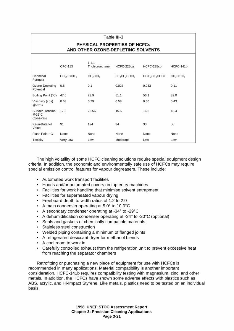
1998 UNEP STOC Assessment ReportChapter 3: Precision Cleaning Applications
Page 3-21
Table III-3
PHYSICAL PROPERTIES OF HCFCsAND OTHER OZONE-DEPLETING SOLVENTS
CFC-1131,1,1-Trichloroethane HCFC-225ca HCFC-225cb HCFC-141b
ChemicalFormula
CCl2FCClF2 CH3CCl3 CF3CF2CHCl2 CClF2CF2CHClF CH3CFCl2
Ozone-DepletingPotential
0.8 0.1 0.025 0.033 0.11
Boiling Point (°C) 47.6 73.9 51.1 56.1 32.0
Viscosity (cps)@25°C
0.68 0.79 0.58 0.60 0.43
Surface Tension@25°C(dyne/cm)
17.3 25.56 15.5 16.6 18.4
Kauri-ButanolValue
31 124 34 30 58
Flash Point °C None None None None None
Toxicity Very Low Low Moderate Low Low
The high volatility of some HCFC cleaning solutions require special equipment designcriteria. In addition, the economic and environmentally safe use of HCFCs may requirespecial emission control features for vapour degreasers. These include:
• Automated work transport facilities• Hoods and/or automated covers on top entry machines• Facilities for work handling that minimise solvent entrapment• Facilities for superheated vapour drying• Freeboard depth to width ratios of 1.2 to 2.0• A main condenser operating at 5.0° to 10.0°C• A secondary condenser operating at -34° to -29°C• A dehumidification condenser operating at -34° to -20°C (optional)• Seals and gaskets of chemically compatible materials• Stainless steel construction• Welded piping containing a minimum of flanged joints• A refrigerated desiccant dryer for methanol blends• A cool room to work in• Carefully controlled exhaust from the refrigeration unit to prevent excessive heat
from reaching the separator chambers
Retrofitting or purchasing a new piece of equipment for use with HCFCs isrecommended in many applications. Material compatibility is another importantconsideration. HCFC-141b requires compatibility testing with magnesium, zinc, and othermetals. In addition, the HCFCs have shown some adverse effects with plastics such asABS, acrylic, and Hi-Impact Styrene. Like metals, plastics need to be tested on an individualbasis.
1998 UNEP STOC Assessment ReportChapter 3: Precision Cleaning Applications
Page 3-22
The use of HCFCs in cleaning equipment may be viewed in terms of two distinctequipment categories -- new equipment and retrofitted equipment. Design changes aremuch easier to implement in new equipment. For example, dual sump open-top degreasers(batch units) can have the same working area but different length and width. A degreaserwith the lesser width will be more solvent efficient in terms of diffusion losses. It would beimpractical, obviously, to consider reorienting sumps on an existing machine in order to takeadvantage of this design feature. New batch units have the vapour generation sump offsetfrom the rest of the machine, again to help minimise solvent losses. Other features on newequipment are: roll-top lids, gasket-sealed water separator lids, and a P-trap installed in thewater drain of the water separator. These features help economise on the use of solvent. Aheat exchanger can be used to keep the rinse sump of a batch cleaning unit lower than theboiling point of the solvent by about 10°C (18°F).
Some of the features mentioned above (e.g., the roll-top lid, gasket-sealed waterseparator lid, and P-trap/water drain of the water separator) are readily applicable toretrofitted equipment. In addition, it is relatively easy to extend the working freeboard.Freeboard height is the distance from the vapour-air interface line (generally at about thesecond primary condenser coil) to the lip of the machine. The freeboard ratio is thefreeboard height divided by the narrowest dimension of the machine, which is normally themachine width. Freeboard ratio is normally expressed as a percentage.
3.3.5 Hydrofluorocarbons (HFCs) and Hydrofluoroethers (HFEs)
HFCs and HFEs are suitable solvent alternatives since their ozone depletion potentials(ODPs) are zero. The pure materials and their blends and azeotropes have the excellentphysical properties of CFCs, such as low surface tension, no flash point and nonflammability. The solvent power of pure HFCs and HFEs is much lower than CFC-113 or1,1,1-trichloroethane solvents. However, the pure materials can be used in certain casessuccessfully. To accomplish more difficult cleaning tasks, blends and azeotropes of thesematerials can be used.
One HFC (e.g. 1,1,1,2,3,4,4,5,5,5-decafluoropentane) and one HFE(1-methoxy-nonafluorobutane) are commercially available and in use as CFC-113 and1,1,1-trichloroethane replacements. Another HFE (1-ethoxy-nonafluorobutane), and possiblysome other substances, are commercially available. Table III-4A shows the properties ofsome of these chemicals and compares them with CFC-113 and1,1,1-trichloroethane. The zero ODP, excellent compatibility and low toxicity of the currentHFCs and HFEs make them suitable replacements for CFC-113 and 1,1,1-trichloroethane insolvent cleaning applications.
The advantages of HFCs and HFEs in precision cleaning include the following:
• moderate-to-excellent cleaning performance (especially with blends, azeotropes andco-solvents)
• the present CFC-113 cleaning equipment can often be used with modifications tominimise emissions
• most assembled units with complex shapes and very small clearances can becleaned and dried easily
• the energy consumption of HFC and HFE cleaning systems is generally smallcompared with aqueous and HCS systems (hydrocarbon surfactant systems)
• unblended HFCs and HFEs are compatible with most metals, plastics andelastomers
• HFC or HFE cleaning equipment generally requires less floor space relative toaqueous and HCS cleaning equipment

1998 UNEP STOC Assessment ReportChapter 3: Precision Cleaning Applications
Page 3-23
• drying is easily and the cleaned parts have no stains• the overall cycle time is much shorter than aqueous or HCS process• exempt from VOC regulations in the U.S. (but not necessarily elsewhere)• the total equivalent warming impact (TEWI) of cleaning processes with HFCs and
HFEs may sometimes be lower than aqueous processes
The disadvantages of HFCs and HFEs include:
• they are more costly on a per kg. basis, therefore they usually require retrofitting ofthe existing equipment or the purchase of modern cleaning equipment. (However,reduced consumption from the equipment retrofitting and good work practices, cankeep the cost per unit cleaned acceptably low)
• on site recycling should be used to minimise emissions, optimise solvent usage andthus minimise overall cleaning costs
• unblended HFCs and HFEs have limited solubility for many soils, thus azeotropes orblends are needed for many applications
• HFCs and HFEs have global-warming potentials (GWPs) and emissions will beregulated.

1998 UNEP STOC Assessment ReportChapter 3: Precision Cleaning Applications
Page 3-24
Table III-4
PROPERTIES OF HFCs and HFEsvs
OZONE-DEPLETING SOLVENTS
CFC-1131,1,1-Trichloroethane HFC-43-10mee HFE-449s1* HFE-569sf2***
ChemicalFormula
CCl2FCClF2 CH3CCl3 CF3CHFCHFCF2CF3
C4F9OCH3 C4F9OC2H5
Ozone-DepletingPotential
0.8 0.1 0.0 0.0 0.0
Boiling Point(°C)
47.6 73.9 55 60 78
Viscosity (cps)@25°C
0.68 0.79 0.67 0.61 0.61
SurfaceTension@25°C(dyne/cm)
17.8 25. 6 14.1 13.6 13.6
Density, (g/ml)@25°C
1.565 1.321 1.58 1.52 1.43
Wetting Index** 129 65 145 183 172
Flash Point °C None None None None None
Toxicity Acute(LC50, 4 hr inppmv)
55,000 16,000 10,000 >100,000 >92,000
ExposureGuideline(ppmv,8 hr TWA inUSA)
1,000 350 200(400 ceiling)
600 TBD
AtmosphericLifetime, yrs
110 6.1 17 4.1 0.8
GWP, 100y 4500 100 1300 480 90
* 2-(difluoromethoxymethyl)-1,1,1,2,3,3,3-heptafluoropropane 1,1,1,2,2,3,3,4,4-nonafluoro-4-methoxybutane
** Calculated from equation: Wetting Index = (density x 1000)/(surface tension x viscosity)
*** 2-ethoxydifluoromethyl)-1,1,1,2,3,3,3-heptafluoropropane 1-ethoxy-1,1,2,2,3,3,4,4,4-nonafluorobutane.

1998 UNEP STOC Assessment ReportChapter 3: Precision Cleaning Applications
Page 3-25
• additional compatibility testing may be needed in some cases, especially forazeotropes of chlorinated solvents, where date is not available for the applicationunder consideration
• toxicological testing for the HFCs resulting in workplace exposure levels beingrecommended for this solvent that are lower than the levels used for CFC-113 and1,1,1-trichlororethane. The workplace exposure levels being recommended for theHFEs are lower than the level used for CFC-113 but above the level1,1,1-trichloroethane
HFCs and HFEs are characterised by the similarity of CFC-113 in physical propertiesbut with zero ODP (Table III-4A). It is expected, therefore, that HFCs and HFEs can be usedin many applications where CFC-113 is used without changes to the non-cleaning parts ofthe manufacturing process. Cleaning equipment changes may be required, however, toreduce emissions from HFCs and HFEs from the cleaning equipment. Applications whereHFCs and HFEs will be used include precision cleaning of disk drives, gyroscopes, hydrauliccontrol systems, oxygen systems, optical components, electric contracts, plastic assembliesand applications of special lubricants or coatings.
So far, HFCs and HFEs have received good evaluations as substitutes for CFC-113(and also for 1,1,1-trichloroethane when the HFCs and HFEs are used in a co-solventprocess or azeotropes) in various precision cleaning applications. Great interest in thesematerials is also anticipated from the medical industry, especially for the flushing andcleaning of disposable plastic devices (e.g. kidney dialysis filters), syringes and IV devices.HFCs and HFEs will find wide usage in these areas where excellent compatibility withplastics and regulatory agency approval (e.g. The U.S. Food and Drug Administration [FDA]or equivalent in other countries) is required and obtained. There are certain applications inprecision cleaning where aqueous and HCS systems cannot be used. HFCs and HFEs areemerging as possible substitutes in such applications.
Unblended HFCs and HFEs are mild solvents, however their solvency power can beenhanced by the formulation of various blends and azeotropes, such as combining HFCsand HFEs with 1,2 trans-dichloroethylene and/or alcohols. Azeotropes or blends with othermaterials, such as chlorocarbons, ketones, esters, ethers, and hydrocarbons may also finduses in specific applications. Unblended HFCs and HFEs are compatible with most metals,plastics and elastomers; however, compatibility of these materials or their formulationsshould be confirmed prior to production implementation of a new cleaning process.Compatibility of HFCs and HFEs with materials which are used in the assembled units to becleaned should be confirmed. Recycling stills suitable for CFC-113 and1,1,1-trichloroethane should work for HFCs and HFEs with appropriate modifications.
The economic and environmentally safe use of HFCs and HFEs may require specialemission control features for vapour degreasers. Examples of such features might include:
• Automated Work transport facilities• Hoods and/or automated covers on top entry machines• Facilities for work handling that minimise solvent entrapment• Facilities for superheated vapour drying• Freeboard depth to width ratios of 1.8 to 2.0• A main condenser operating at 4-13 degrees C• A secondary condenser operating at ca. -20 degrees C• A dehumidification condenser (optional)• Seals and gaskets of chemically compatible materials• Stainless steel construction• Welded piping containing a minimum of flanged joints

1998 UNEP STOC Assessment ReportChapter 3: Precision Cleaning Applications
Page 3-26
• A refrigerated (optional) desiccant dryer for methanol (or other water solublecomponents) blends are azeotropes
• A cool, draught-free work room that contains the cleaning equipment• Carefully controlled exhaust from the refrigeration unit to prevent excessive heat
from reaching the separator chambers
Retrofitting or purchasing a new piece of cleaning equipment for use with HFCs andHFEs is recommended for many applications. After careful review, it may be more costeffective to purchase new equipment than to retrofit existing equipment, especially if theoverall operating costs of the process will be lower with the new equipment.
The use of HFCs and HFEs in cleaning equipment may be reviewed in terms of twodistinct equipment categories — new equipment and retrofitted equipment. Design changesare much easier to implement in new equipment. For example, dual sump open-top vapourdegreasers (batch units) can have the same working area but different length and width. Adegreaser with the lesser width will be more solvent efficient in terms of diffusion losses. Itwould be impractical, obviously, to consider reorienting sumps on an existing machine totake advantage of this design feature. New batch units have the vapour generation sumpoffset from the rest of the machine, again to help minimise solvent losses. Other features onnew equipment are: roll-top lids, gasket-sealed desiccant dryer lids, gasket-sealed waterseparator lids, and a trap installed in the water drain line of the water separator. Thesefeatures help economise on the use of solvent. A heat exchanger can be used to keep therinse sump of a batch cleaning unit lower than the boiling point of the solvent by about 5degrees C.
Some of the features mentioned above (e.g., the roll-top lid, gasket-sealed waterseparator lid, and trap in the water drain of the water separator) are readily applicable toretrofitted equipment. In addition, it is relatively easy to extend the working freeboard.Freeboard height is the distance from the vapour-air interface line (generally at about thesecond primary condenser coil) to the lip of the machine. The freeboard ratio is thefreeboard height divided by the narrowest dimension of the machine, which is normally themachine width. Freeboard ratio is normally expressed as a percentage.
It is often feasible to use existing modern vapour degreasing equipment for the co-solvent process without retrofitting.
3.3.6 Alcohols and Ketones
The most common organic solvents are alcohols such as ethanol, isopropanol, andseveral glycol ethers (methyl, n-butyl, and diethyl). Most of these solvents are chosen fortheir high polarity and for their very effective solvent power. The alcohols have a range offlash points and care must be exercised while using the lower flash point alcohols (seeTable III-4B).
Based on material compatibility, alcohols are viable alternatives for componentcleaning. Explosion-proof boiling alcohol cleaners using isopropanol could be a practicalalternative to CFC-113 and 1,1,1-trichloroethane in many applications. For bulk cleaning ofparts at the incoming stage, this alternative could be considered; large-scale isopropanoluse may be unacceptable within clean room areas, however, because of flammability risksand operator discomfort resulting from alcohol odours as well as the dehydrating effect ofalcohol solvent and vapours on skin surfaces.

1998 UNEP STOC Assessment ReportChapter 3: Precision Cleaning Applications
Page 3-27
Table III-4b
PROPERTIES OF ALCOHOLS
1 N-Butyl Acetate = 1
NOTE: FL.PT. = Flash Point Closed Cup Test; SP.GR. = Specific Gravity.Source: Southwest Chemical Company, Solvent Properties Reference Manual
Product LB/GAL15.6°C
SP. GR.20°/20°C
BoilingRange °C
FL. PT.°C TCC
Evap.Rate 1
Methanol 6.60 0.792 64-65 12 3.5
Ethanol. Prop. Anhydrous 6.65 0.799 74-80 9 1.8
Ethanol, Spec. IndustrialAnhydrous
6.65 0.795 75-81 10 1.8
Isopropanol, Anhydrous 6.55 0.786 82.83 12 1.7
n-Propanol 6.71 0.806 96-98 23 1.0
2-Butanol 6.73 0.809 97-102 22 0.9
Isobutanol 6.68 0.803 107-109 29 0.6
n-Butanol 6.75 0.811 116-118 36 0.5
Amyl alcohol (primary) 6.79 0.815 127-139 49 0.3
Methyl Amyl Alcohol 6.72 0.808 130-133 39 0.3
Cyclohexanol 7.89 0.949 160-163 61 0.05
2-Ethylhexanol 6.94 0.834 182-186 73 0.01
Hexanol 7.90 0.950 244-247 120 0.002

1998 UNEP STOC Assessment ReportChapter 3: Precision Cleaning Applications
Page 3-28
Isopropanol and acetone operating in conjunction with ultrasonics have been evaluatedas alternatives to CFC-113 in precision cleaning (Mobjork 1989). Care must be taken whenusing flammable solvents in ultrasonic baths due to the potential for solvent ignition andfires. The following components and instruments were subjected to overall evaluation in thistesting:
• Servo component system• Hydraulic series ram screw• Accelerometer cut-out• Horizon indicator• Horizon gyroscope• Gyroscope motor components• Flight position indicator• Turn and bank indicator• Reduction vent valve for oxygen• Oxygen pressure regulator• Parachute swivel connector
All components and instruments were retrieved from production except for the oxygenvent and pressure regulator which were manually contaminated. Due to the flammability ofisopropanol and acetone, special explosion-proof batch vapour-phase cleaners were used inthis evaluation 10. A number of precision components were cleaned in isopropanol oracetone.
Cleaned with isopropanol:
• Swivel connector parts contaminated with low temperature grease• Gyroscope instruments• Reduction vent valve connections in an oxygen system contaminated with oils and
greases• Oxygen system gas regulators contaminated with soot and char
Cleaned with acetone:
• Servo-gear piston contaminated with anti-corrosion oil• Series servo contaminated with hydraulic oils, grease, and particulate matter (or
particles)• Accelerometer cut-out contaminated with silicone oil
Isopropanol proved to be a viable substitute for CFC-113 and generally is compatiblewith non-metallics. However, the use of acetone as a viable alternative needs to be studiedcarefully since it is highly aggressive toward many polymers.
------------------------------------------------10 These ultrasonic vapour-phase cleaners are designed for flammable liquids. The machines are fire- andexplosion-proofed according to the DIN-standards and approved by the Federal Republic of Germany´s TUVauthority.

1998 UNEP STOC Assessment ReportChapter 3: Precision Cleaning Applications
Page 3-29
3.3.7 Perfluorocarbons
The perfluorocarbons (PFCs) are a group of fluorine-saturated hydrocarbons(compounds in which all the hydrogen atoms of the hydrocarbon are substituted by fluorine).Because of the extreme electronegativity of the fluorine atom, this saturation results in highchemical stability in all of the compounds. Consequently, they are virtually chemically inert,exhibit low toxicity, are non-flammable, and have zero ozone-depletion potential. As a resultof this very low chemical activity, PFCs can be used in medical applications and are safe incontact with pure oxygen at high pressures. Their stability, however, makes PFCs extremelypotent global warming compounds. Due to their high global warming potential (GWP), theuse of PFCs is restricted in a number of countries.
Choice of base hydrocarbon provides a wide range of molecular weight and molecularstructure resulting in a range of boiling points. Table III-5 shows some of the basicproperties of PFCs that were commercially available in late 1994.
Besides their GWP, another major disadvantage of PFCs is their high cost which is aresult of the complex synthetic production processes. A typical low- to mid-range boilingPFC, for example, is approximately $26 to $30 US per kg. The high cost of thesecompounds should encourage potential users to use PFCs only in vapour-tight equipment,reducing the amount of PFCs that are lost to the atmosphere. Another drawback is thatPFCs have very low solvency power for hydrocarbons and are unlikely to be very useful forremoving oils. They have been shown, however, to be excellent solvents forperfluoropolyethers and other halogenated compounds.
Where no other substitutes are feasible, PFCs offer possible solutions to currentCFC-113 and 1,1,1-trichloroethane users, particularly in cleaning parts for high accuracygyros. Some current high-density flotation fluids are soluble in certain PFCs, which cantherefore be used for flushing filled assemblies. In addition, high pressure spraying withPFCs appears to be a very effective method of particle removal. The excellent chemicalstability of these fluids makes them compatible with all gyro construction materials includingberyllium. Table III-6 summarises the compatibility of PFCs with various materials.
Design of equipment for gyroscope or other precision parts cleaning will have to bespecific to each application. Whatever type of equipment is designed, it should be a vapour-tight system to facilitate reclamation and recycling. The chemical stability of PFCs makesthem excellent compounds for recycling. Currently, suppliers offer reclamation and recyclingprograms for these compounds, thus minimising emissions that could contribute to globalwarming 11. If vapour-tight equipment is not utilised, the evaporative loss of PFC would beprohibitively expensive and would make the use of PFCs very difficult to rationalise (evenconsidering the high cost and strategic importance of the products).
------------------------------------------------
11 Preliminary studies by one equipment manufacturer have demonstrated emission reductions of 90 percent forPFCs compared to historical emissions of CFC-113

1998 UNEP STOC Assessment ReportChapter 3: Precision Cleaning Applications
Page 3-30
3.3.8 Aliphatic Hydrocarbons
Aliphatic hydrocarbons, which offer tight control on composition, odour, boiling range,evaporation rate, etc., are employed in original equipment manufacturer (OEM) cleaningprocesses and will be discussed below.
The advantages of aliphatic hydrocarbon cleaners include:
• Compatible (non-corrosive) with most rubbers, plastics and metals• Employs no water, hence can clean water-sensitive parts• Low odour and low toxicity grades available• Reduced evaporation loss• No wastewater stream
Table III-5
Comparison of Properties of Perfluorocarbon Solvents Available
Basic Formula C5F11NO C6F14 C7F16 C8F18 CFC-113 1,1,1-Trichloro-ethane
Ozone DepletingPotential
0 0 0 0 0.8 0.10
Global WarmingPotential 1
7500 7400 7300 2 7200 4500 100
Boiling Point °C 50 56 80 101 47.6 73.9
Density, g/ml,25°C
1.70 1.68 1.73 1.77 1.57 1.33
Viscosity, cP,25°C
0.68 0.67 0.95 1.4 0.68 0.79
Surface Tension,dynes/cm, 25°C
13.0 12.0 13.0 15 19.0 25.6
SiliconeSolubility
Very Low Very Low Very Low Very Low High Moderate
FluorocarbonSolubility
High High High High High High
SolubilityParameter H
6.3 5.6 5.7 5.7 7.3 7.7
Flash Point, °C None None None None None None
ApproximateCost, US$/kg
26 26 28 30 22 7
1 Based on 100-year time horizon2 Estimated

1998 UNEP STOC Assessment ReportChapter 3: Precision Cleaning Applications
Page 3-31
Table III-6
PERFLUOROCARBON (PFC) COMPATIBILITX WITH VARIOUS MATERIALS
Class of Material Observation
Rubbers <1 percent linear swell, ± 1 percent change inweight
Polyethylene, polypropylene <1 percent shrinkage, zero change in weightNylons Negligible change in dimensions or weightPolystyrene Variable, generally negligible, shrinkage (e.g.
0.2 percent)PMMA <0.2 percent shrinkage, slight loss in weightPTFE (unfilled) 2-3 percent linear swell, up to 10 percent
increase in weightPVC (Rigid) Negligible changePVC (Flexible) Extraction of plasticizer, loss of flexibility (in hot
Flutec)Electronic circuit boards * ± <0.1 percent dimensional change, zero
change in weightCopper and brass Slight tarnishing (from dissolved oxygen)Other Common metals No effect detectableSilicone and microcircuit chips No known effectAdhesivesAdhesive tapesPaperEnamelled wiresInsulating tapesPaintsOther surface coatings and sealants
No adverse effects detected in any samples
tested up to the present time
____________* Including: SRBP, Epoxy, DAP, Silicone, Melamine, Polyester, with filler materials of all commontypes

1998 UNEP STOC Assessment ReportChapter 3: Precision Cleaning Applications
Page 3-32
• High stability and recovery• Recyclable by distillation• Good cleaning ability for wide variety of soils, especially heavy grease, tar, waxes,
and hard to remove soils. Low surface tension allows good penetration.
The disadvantages include:
• Flammability concerns (can be solved with proper equipment design)• Slower drying times than halogenated solvents• VOC control may be required. However, equipment such as carbon adsorption amd
condensers can recover solvent from effluent air• Waste products are classified as hazardous waste• Low occupational exposure limits are associated with some grades.
A wide range of aliphatic hydrocarbon solvents are used in precision cleaning (seeTable III-7). Petroleum fractions, commonly known as mineral spirits or naphtha, are usedextensively in maintenance cleaning. These are single stage, open-top processes usingambient air drying. In most cases such processes are not suitable for Original EquipmentManufacture (OEM) cleaning.
The major steps in the hydrocarbon cleaning process are washing (1-3 stagesdepending on degree of cleaning needed) with a hydrocarbon cleaner, drying using forcedair, VOC recovery from solvent-laden air, and waste-solvent recovery or disposal. The washsteps involve liquid-phase cleaning at temperatures sufficiently below the flash point of thefluid. Ultrasonics or other agitation processes such as immersion spraying, parts rotation, orfluid pump around can be used to augment cleaning action. (However, note that ultrasonicequipment manufacturers do not recommend the use of ultrasonics with flammablesolvents.) Spraying or misting processes, where fine droplets are formed, should beemployed only in an inert environment or with equipment otherwise protected from ignitionconditions, because fine droplets can be ignited at temperatures below bulk fluid flash point.
Fluids with flash points near 40°C (104°F) or below should be used in unheatedequipment operating at ambient temperatures, although the continued use of refrigerationcoils is preferred. For higher flash points, hot cleaning can be employed to boost cleaningaction. For systems with good temperature control (independent temperature sensors, cut-outs, level indicators, etc.), a safety margin of 20°C (36°F) between the fluid flash point andthe cleaning temperature, or 90 percent below the lower explosive limit (LEL), isrecommended. For systems with poorer temperature control, a higher margin should beemployed.
Each wash step should be followed by a drain period, preferably with parts rotation, tominimise solvent drag-out from stage to stage.
In multistage processes, fluid from one bath is periodically transferred to the precedingbath as its soil level builds up. Fresh solvent is thus added only to the final bath to ensurethe highest parts cleanliness, and spent solvent is removed only from the first stage.
The drying step normally uses forced air which may be heated. Either the dryer shouldoperate at 15°C below the flash point of the fluid, or sufficient air flow should be provided sothat the effluent air composition is well below the Lower Explosive Limit (LEL) of the system.

1998 UNEP STOC Assessment ReportChapter 3: Precision Cleaning Applications
Page 3-33
The VOC recovery step is an important part of the cleaning process. Depending on thesolvent chosen, either carbon adsorption or condensation are the best technologies forrecovery of solvent vapours from spent drying air and lip vent air. There are numerousvendors of such recovery equipment.
In the waste recovery area, the best reclamation technology for these products isusually filtration and distillation. One of the advantages of the low olefin content and narrowdistillation range is that the recovery in distillation is high. Should some disposal of residualsolvent be necessary, fuel substitution and incineration are good routes.
Table III-7
PROPERTIES OF ALIPHATIC SOLVENTS
Product LB/GAL15.6°C
SP.GR.15.6/15.6
BoilingRange °C
FL.PT.°C TCC
KB Evap.Rate 1
Mineral Spirits 6.37 0.764 152-202 41 32 0.1
Odourless Mineral Spirits 6.33 0.760 177-202 53 27 0.1
140 Solvent 6.54 0.786 182-210 60 30 0.1
Kerosene 6.60 0.790 166-257 54 30 0.19
C10/C11 Isoparaffin 6.25 0.750 160-171 42 29 0.3
C13 N-Paraffin 6.35 0.760 227-238 93 22 0.1
C10 Cycloparaffin 6.75 0.810 166-182 41 54 0.2
1 N-Butyl Acetate = 1NOTE: FL.PT. = Flash Point Closed Cup Test; KB = Kauri-Butanol Value;SP.GR. = Specific Gravity
Source: Southwest Chemical Company, Solvent Properties Reference Manual; ExxonChemical Company

1998 UNEP STOC Assessment ReportChapter 3: Precision Cleaning Applications
Page 3-34
3.3.9 Chlorinated and Other Miscelleaneous Organic Solvents
The precision cleaning industry has always used a very wide range of miscellaneoussolvents. In all applications such solvents are used for manual operations, usually by meansof camel or sable hair brushes during assembly or rework. In addition to those alreadydescribed, other chlorinated solvents, ethers, ketones, alcohols, and esters, are alsocandidate replacements for precision applications. Typical uses are local defluxing aftersolder rework operations, defluxing after special solder operations (e.g., strain gauge leadattachment), and varnish applications (e.g., small scale in-situ coil impregnations).
The chlorinated solvents that do not destroy the ozone layer, trichloroethylene,perchloroethylene, and methylene chloride (dichloromethane) also are effective cleaners.Because of their widespread use, they have been scrutinised for their safety, health, andenvironmental impacts. Many countries have established exposure levels that areconsidered safe for workers. In addition, many countries have placed additional controls onemissions to the atmosphere from processes using these solvents. Local regulations,Material Safety Data Sheets, and industrial recommendations such as those of theAmerican Conference of Governmental Industrial Hygienists should be used as guidance inestablishing safe handling and usage procedures for these solvents.
The development of extremely low emissions cleaning equipment which minimisesworker exposure levels, and emissions to the environment, along with good managementpractices offers users an alternative that provides for equivalent or better cleaning withexisting technology. The combination of limits being placed on users will require their useonly in applications where emissions are very carefully controlled. Table III-8 summarisesthe properties of these other chlorinated solvents.
The ketones (see Table III-9) form a group of very powerful solvents. In particular, acetone(dimethyl ketone) and methyl ethyl ketone are very good solvents for polymers andadhesives. In addition, acetone is an efficient dewatering agent. However, their extremeflammability (note that acetone has a flash point of -18°C) and incompatibility with manystructural polymers (e.g., stress-cracking of polyether sulphone, polyether ketone, andpolycarbonate) means that they should only be used with care and in small quantities.Consequently, large-scale use as CFC-113 or 1,1,1-trichloroethane alternatives would beunlikely.
Esters such as dibasic esters have good solvent properties. Most of these materials arereadily soluble in alcohols, ketones, ethers, and most hydrocarbons, but are only slightlysoluble in water and high paraffinic hydrocarbons. The materials have high flash points andlow vapour pressures. Dibasic esters, however, are so low in vapour pressure that a residualfilm will remain on a surface after application. In addition, they have been found to begenotoxic and should therefore be used with caution.
n-Propylbromide has been introduced as an alternative solvent with applications inprecision cleaning. n-Propylbromide (nPB) does exhibit an ozone depletion potential.Studies are underway to determine the global warming potential (GWP) as well as itsvolatile organic compound (VOC) status. The US EPA is in the process of listing nPB in theFederal Register for the purpose of eliciting comments as to the viability of nPB in thesolvent sector.Since nPB does possess an ODP, it has been reported to the UNEP OzoneSecretariat as not being recommended by the Solvents Technical Options Committee(STOC) under decision IX/24 of the Parties to the Protocol. Further, it is unlikely that it wouldbe approved for use in Art. 5(1) nations for aid under the Multilateral Fund.n-Propylbromide presents a serious danger to the ozone layer because of its lower cost,extensive quantities may be used and present a formidable impact on the ozone layer.

1998 UNEP STOC Assessment ReportChapter 3: Precision Cleaning Applications
Page 3-35
Chlorobromomethane, CBM, has been advertised as a precision cleaning solvent.Unfortunately, CBM has not been represented accurately with specific references toacceptance by US federal agencies. CBM is not recommended as a solvent by the STOC inany area. The toxicity of CBM has long been known and, if only for this reason CBM shouldnot be considered for any cleaning application.
Table III-8PROPERTIES OF HALOGENATED CHLORINATED SOLVENTS
PhysicallProperties
CFC-113 1,1,1-Trichloro-
ethane
Trichloro-ethylene
Perchloro-ethylene
Methylene Chloride
Ozone-DepletingPotential
0.8 0.1 0 0 0
ChemicalFormula
CCl2FCClF2 CH3CCl3 CHClCCl2 CCl2CCl2 CH2Cl2
MolecularWeight
187.38 133.5 131.4 165.9 84.9
Boiling Point (°C) 47.6 72-88 86-88 120-122 39.4-40.4Density (g/cm3) 1.56 1.34 1.46 1.62 1.33SolubilityParameter,Hildebrand
7.7 9.2 9.3 9.7 9.7
Surface Tension(dyne/cm)
17.3 25.4 29.3 31.3 N/A
Kauri ButanolValue
31 124 130 91 132
Toxicity Low Low Medium Medium MediumCarcinogenicity No No See Note a See Noe b See Note c
Flash Point (°C) None None None None None_____________
a The U.S. EPA has not formally classified trichloroethylene in Category B2 as a "probable humancarcinogen“, while the International Agency for Research on Cancer (IARC) has classified this solvent inGroup 3, substance not classifiable as to its carcinogenicity in humans.
b The U.S. EPA has not formally classified perchloroethylene in Catgeory B2 as a "probable humancarcinogen“. IARC has classified perchloroethylene in Group 2B as a substance considered "possiblycarcinogen to humans“.
c The U.S. EPA has classified methylene chloride in Category B2 as a "probable human carcinogen“, whileIARC has classified methylene chloride in Group 2B as a substance considered "possibly carcinogenic tohumans“.
Source: UNEP (1989)

1998 UNEP STOC Assessment ReportChapter 3: Precision Cleaning Applications
Page 3-36
Table III-9
PROPERTIES OF KETONES
KETONE Formula Mol. Wt. lbs per gal B.P. °C Flash Point°C opencup
Evap RateCCl4=100
SolubilityParameterH
SurfaceTension20°CDynes/cm
Acetone C2H6CO 58.08 6.58 56-57 -17 139 9.9 23.7
Methyl EthylKetone (MEK)
C3H6C0 72.10 6.71 79-81 -2.2 97 9.3 24.6
Diethyl Ketone C4H10CO 86.13 6.80 100-104 12.6 -- 8.8 24.8
Methyl n-PropylKetone
C4H10CO 86.13 6.72 101-107 7.2 66 8.7 25.2
Cyclohexanone C5H10CO 98.14 7.88 130-172 62 12 9.9 --
Methyl IsobutylKetone (MIBK)
C5H12CO 100.16 6.68 112-118 17.6 45 8.4 22.7
Methyl n-ButylKetone
C5H12CO 100.16 6.83 114-137 22.5 32 8.3 25.5
MethylCyclohexanone
C6H12CO 112.7 7.67 114-173 47.3 7 9.3 --
AcetonylAcetone
C4H10(CO)2 114.4 8.10 185-195 78 -- -- 39.6
DiisopropylKetone
C6H14CO 114.18 6.73 114-127 23.6 -- 8.0 --
Methyl n-AmylKetone
C6H14CO 114.18 6.81 147-154 48.4 15 8.5 --
Diacetone C5H12CO 116.16 7.82 130-180 8.8 4 -- 29.8
Source: A.F. Barton, Handbook of Solubility Parameters and Other Cohesion Parameters,CRC Press
3.3.10 Pressurised Gases
Particulate contamination may be removed with pressurised gases as an alternative tocleaning with CFC-113 and 1,1,1-trichloroethane. However, the use of these gases will notgenerally remove ionic or organic contamination (see the section on supercritical fluids).Primary considerations for choosing pressurized gases depend on the following properties:
• Surface chemistry. This factor is ultimately responsible for the nature of theelectrostatic forces between surfaces.
• Porosity. Porous (and rough) surfaces possess the potential to mechanically lock
contaminant and substrate and further hinder the cleaning process.

1998 UNEP STOC Assessment ReportChapter 3: Precision Cleaning Applications
Page 3-37
• Roughness of surface. Large particles on a smooth surface may be removed moreeasily than small particles on a rough surface for the same reason.
• Size, shape, and homogeneity of the contaminant. On a microscopic level, all
surfaces possess ridges and valleys that make intimate contact between surfacesdifficult. Adsorbed contamination on particles and other surfaces also hinders contactand prevents relatively short-range molecular interactions from occurring.
• Sensitivity of the surrounding area to ejected material. Relatively inert gases and
mixtures are most often used with specially designed equipment to meet thecleanliness requirements of the surrounding area.
Depending upon which pressurised gas is used in the cleaning application, theadvantages of using pressurised gases versus halogenated solvent cleaning could includethe following:
• Low viscosity• Low toxicity• High diffusivity• Non-flammability• Low capital cost.
The disadvantages of using pressurised gases could include:
• Low density• High pressure (rupturing of seal)• Cleaning of critical components• Often not effective for microscopic particles• Safety considerations.
Possible Gases:
Gases which may be used include air, rare gases, carbon dioxide,1,1,1,2-tetrafluoroethane (HFC-134a), and nitrogen. These gases are readily available inbulk and smaller quantities and in numerous grades of purity. These gases may be stored atroom temperature. Dry air is produced from ordinary air by removing hydrocarbons byoxidation. Carbon dioxide is then removed and the air is compressed and dried.
Because of its oxygen content, air reacts with many substances, rare earth gases,however, are noted for their extreme chemical inactivity. These monatomic gases arehelium, neon, argon, krypton, and xenon and may be obtained by fractionation of liquid air.Argon, the most abundant of the rare earth gases, is commercially available in cylindersranging from 1,775 to 6,000 psig at 21.1°C. Argon is not toxic, but is an asphyxiant and isheavier than air.
Carbon dioxide, which is recovered from a number of processes, is colourless,odourless, non-flammable, and slightly acidic. The gas is stable under most conditions, but itwill dissociate into carbon dioxide and carbon monoxide in the presence of free carbon athigh temperatures. For example, at 100°C, the equilibrium ratio of carbon dioxide to carbonmonoxide is 0.7 percent to 99.3 percent. Above the critical temperature of 31°C, all solidcarbon dioxide converts to a gas. It may be shipped under its own vapour pressure of830 psig at 21.1°C. Caution must be taken in dealing with carbon dioxide since it acts as anasphyxiant and cumulative amounts of the gas can act like a poison. Note that the use of

1998 UNEP STOC Assessment ReportChapter 3: Precision Cleaning Applications
Page 3-38
carbon dioxide does not contribute to global warming because the source of most carbondioxide is the air itself.
Colourless and non flammable, HCFC-22 has an ozone-depletion potential of 0.05. Athigh temperatures, various metals may catalyse decomposition of the gas. Silver, brass,bronze, aluminium, 1340 steel, copper, nickel, 18-8 stainless steel, and inconel react indescending order, with silver being the most reactive. Magnesium and aluminum alloys withtwo percent or more magnesium are particularly reactive in the presence of water. Naturalrubber may also be swollen and degraded by the solvent. Continued flooding of localisedareas with liquid produces rapid chilling. This feature may be desirable to remove moretenacious contaminants. It is often shipped as a liquefied gas under its own pressure of123 psig at 21.1°C. The gas is available in bulk and small disposable cans. Direct contactwith liquid chlorodifluoromethane may cause frostbite. The gas is considered to be non-toxic, but high concentrations can produce dizziness, narcosis, and nausea.
Equipment Considerations:
Clean dry air may be economically produced from pressurized air inhouse. Specificallydesigned diaphragm and other non-contaminating pumps are available. High efficiencyfilters, drying agents, and other equipment can be used for most of these gases.
A problem inherent in cleaning with high-pressure gases is the development of staticcharges. Ionising guns that can alleviate this problem are available from clean roomequipment suppliers.
Typically, clean, dry, inert gas, or air is fed to a pressurised gas gun at 689.5 kPa. Manymodels offer 0.3 to 0.5 micron particle filtration with a maximum outlet pressure of ionisedgas at 207 kPa. Different ionising and filtration techniques have been designed for specificneeds. One model is reported to remove 3.0 micron size particles with 99 percent efficiencyfrom bare silicon wafers.
Composition of the contaminant and substrate may determine whether or not ejectedmaterial produced by pressurised gas will damage surrounding surfaces. Metal dust may beeasily removed from an assembly with pressurised gas. However, if an optical componentwith a sensitive coating is part of the assembly, impinging particles could scratch it. Particleswith low mass may not present a problem. Likewise, harder components may be resistantenough to allow this process. Consideration of dislodged particles is not limited to resistanceof the assembly or part because the clean room requirements, as well as the surroundingstructure, may not tolerate increased levels of contamination.
Containment of ejected debris may be accomplished for small parts by operating theprocess in a laminar flow work station equipped with a high efficiency particulate air filter oran ultra-low penetration air filter. Vacuum may also be used with pressurised gas on someparts to capture dislodged contamination.
3.3.11 Supercritical Fluids
The use of supercritical fluids (SCF), especially carbon dioxide, has escalated in theearly 1990's. SCFs are chemicals that are normally liquid or gaseous at standardtemperature and pressure. However, when the pressure and temperature are increased tospecific levels, the chemical reaches a supercritical state and exhibits very different solventproperties. Table III-10 lists some of the data for typical supercritical solvents.

1998 UNEP STOC Assessment ReportChapter 3: Precision Cleaning Applications
Page 3-39
In the case of supercritical carbon dioxide (CO2), the fluid has been used for manyyears in the food and flavour industry. One example is the use of supercritical CO2 todecaffeinate coffee. The properties of the SCFs are such that at each temperature andpressure combination within the supercritical region, the fluid behaves with slightly differentsolvency powers. In the coffee decaffeination example cited above, the coffee beans areloaded into a very large, high-pressure reactor. The CO2 is injected into the reactor and thepressure and temperature are simultaneously increased. The coffee bean flavour an organicchemical itself is first removed from the beans by adjusting the pressure and temperatureand then releasing the carbon dioxide to a capture chamber, where the flavour is held.Then, the reactor is refilled with CO2, and adjusted to a different temperature and pressureand the caffeine is removed and captured into another holding chamber. Finally, thepressure and temperature combination of the coffee flavour is readjusted and the flavour isadded back to the beans.
The equipment for a supercritical CO2 cleaning system can start at between $60,000 to$120,000 for small reactors of approximately 1 cubic foot capacity. The cost of the unitdepends on the types of soil to be removed and the size of the high-pressure reactor. It iscommon for the reactors to be operated in the 2000 to 5000 psi range with temperaturesbetween 40°C to 110°C.
Compared to liquid solvents such as CFC-113 and 1,1,1-trichloroethane, SCFs have ahigher diffusivity and a much lower density and viscosity. This combination of characteristicsallows for rapid extraction of contaminants and phase separation. Other chemicals, such asnitrous oxide, ethane, ethylene, and water, can be used in supercritical cleaning processes,but CO2 has proven to be the safest, the most abundant and economical, and very effective.Supercritical fluids display the following properties:
• wide range of solvent solubilities• gas-like diffusivity• zero surface tension• short process times• low energy costs• does not generate waste products (except for the conamination removed)• gas is completely recoverable

1998 UNEP STOC Assessment ReportChapter 3: Precision Cleaning Applications
Page 3-40
Table III-10
DATA FOR TYPICAL SUPERCRITICAL SOLVENTS
Solvent CriticalTemperature
(deg. C)
CriticalPressure
(atm)
Density (g/cm3)
Methane -83 45.4 0.16
Ethylene 9 49.7 0.22
Chlorotrifluorome-thane
29 38.7 0.58
Carbon dioxide 31 72.8 0.47
Ethane 32 48.2 0.20
Nitrous oxide 36 71.5 0.45
Sulfur hexafluoride 45 3.1 0.74
Propylene 92 45.6 0.23
Propane 97 41.9 0.22
Ammonia 132 111.3 0.24
Trichlorofluoro-methane
198 43.5 0.55
n-Hexane 234 29.3 0.23
Isopropanol 235 47.0 0.27
Ethanol 243 63.0 0.28
Toluene 318 40.6 0.29
Water 374 217.7 0.32
SCFs exhibit many properties of an ideal process, however the high cost of theequipment and the necessary process development to fine-tune the cleaning process willrequire significant funding. Some characteristics of the SCF process that should beconsidered include potential material compatibility problems and the necessary training foroperators of the high-pressure equipment. SCF processes should be targeted to industrieswhere expensive fluids are to be removed from precision hardware, specifically the medical,space, and defence industries.
Test results obtained by one company using SCF cleaning for development tests onprecision gyroscopes for high-reliability use indicate the following:
• effective removal of oils and polyhalogenated fluids• pressures and temperatures required• -- perfluoropolyether oils ... 1500 psi, 170°F
-- halogenated and other oils ... 3500 psi, 185°F• incompatible with hermetically sealed devices• effective for deep pores (width/diameter of 650 to 10,000)• material compatibilities

1998 UNEP STOC Assessment ReportChapter 3: Precision Cleaning Applications
Page 3-41
-- metals, ceramics, and glass were good-- thermoset plastics were good-- thermoplastics were fair to good-- elastomers (rubber) were bad, except for silicones
Supercritical carbon dioxide has been tested by several users as a potentialreplacement for precision cleaning with CFC-113 and 1,1,1-trichloroethane. Table III-11illustrate the types of applications that have been successful. It is important to confirm thatthe cleanliness achieved in each application matches the precision cleaning requirements.
Process Overview:
Carbon dioxide is pressurised and heated to its supercritical state and introduced intothe extraction vessel at the selected extractor operating conditions. In the extractor, thesupercritical fluid selectively extracts one or more components from the source material. Thesolute-rich gas exits the extractor and undergoes a temperature and/or pressure change.This change decreases the solubility of the solute in the fluid and, due to the change insolubility, a solute/fluid separation takes place in the separator vessel.
In order to determine whether SCF is a technically feasible and economically viablealternative, it is necessary to evaluate phase equilibrium properties of the fluids. Theseinclude the number of phases present, the composition and density of each phase, and theequilibrium changes associated with temperature, pressure, and composition. This isimportant because of the often-complex behaviour of fluids in high-pressure phase. Phaseequilibrium and mass transport data is used to size equipment, determine utilityrequirements, and estimate costs.
The pressure-dependent dissolving power of CO2 is not limited to polymers and oils ofonly medium molecular weight and materials of low polarity. Very highly polar materials suchas alcohols and organic acids are soluble, and among polymeric materials, many polymersand high molecular weight oils, such as silicones and fluoroethers, commonly associatedwith gryoscopes are soluble; silicones of several hundred thousand MW dissolve to highlevels in supercritical CO2. For completeness here, SC CO2 can dissolve manyhydrocarbons, esters, silicones, perfluorinated oils, halocarbon-substituted triazines, andpolychloro- and bromo-trifluoethylene; these materials can also be fractionated based onmolecular weight which has special purpose application in lubrication and coating. Whilethere are polymers that are insoluble in CO2, some of them - depending on the degree ofcross-linking and crystallinity - may exhibit swelling and/or incompatibility of CO2.
Unfortunately, there are also many confusing claims which continue to be perpetuatedthroughout the literature and patents regarding the ability of SC CO2 to dissolve particles(e.g., lint, dust, scale, metal, and salts, etc)., fluxes, and other materials. While it is possiblethat some dislodging of particles can occur due to velocity forces, they do not dissolve inCO2. Based on extensive investigation with rosin based fluxes, it can be stated with certaintythat these materials are insoluble in carbon dioxide. Some of the confusion may arisebecause of incompletely understood phenomena. For example, abietic acid (the maincomponent of rosin) is soluble in CO2 and it is interesting that a recent international patentapplication has stated that abietic acid must be modified with methanol to impart anyreasonable solubility in CO2. The confusion arises because after exposure to hightemperatures required for melting solder, abietic acid can polymerize enough to render theflux residue insoluble. Even many low-solids and water-soluble fluxes are insoluble in CO2;thus SC CO2 is not generally applicable to circuit board cleaning (although in special cases itmay show limited results).
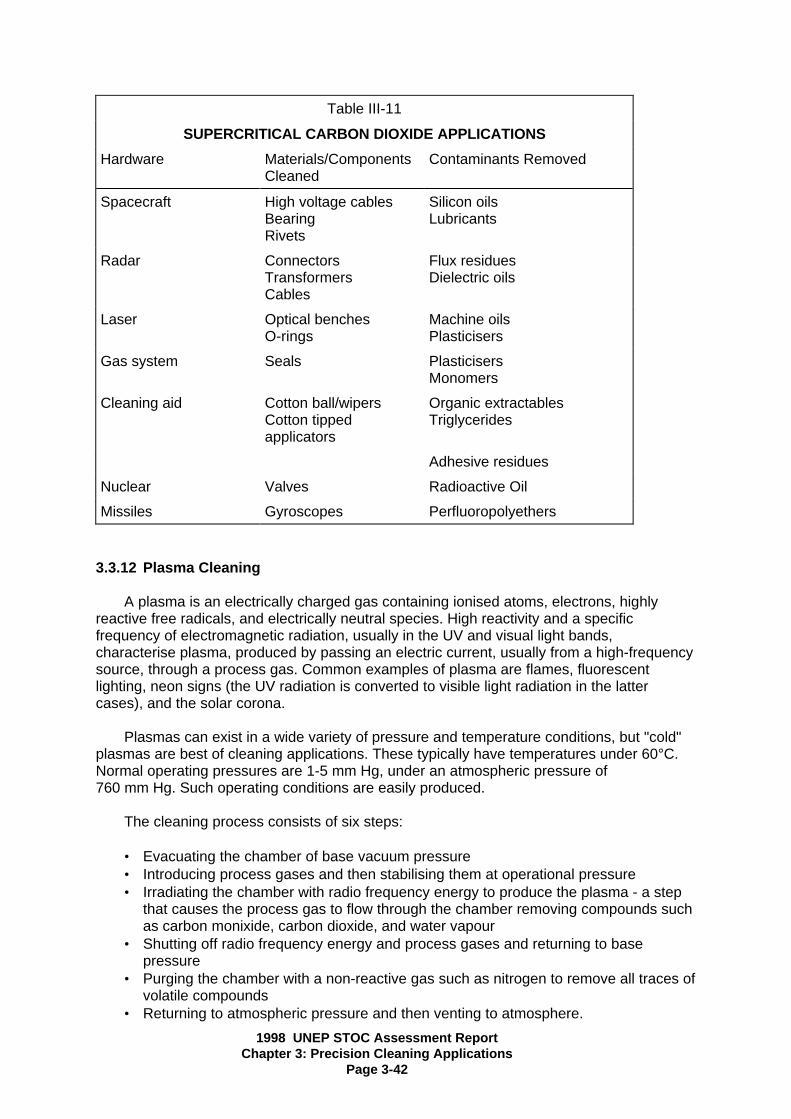
1998 UNEP STOC Assessment ReportChapter 3: Precision Cleaning Applications
Page 3-42
Table III-11
SUPERCRITICAL CARBON DIOXIDE APPLICATIONS
Hardware Materials/ComponentsCleaned
Contaminants Removed
Spacecraft High voltage cablesBearingRivets
Silicon oilsLubricants
Radar ConnectorsTransformersCables
Flux residuesDielectric oils
Laser Optical benchesO-rings
Machine oilsPlasticisers
Gas system Seals PlasticisersMonomers
Cleaning aid Cotton ball/wipersCotton tippedapplicators
Organic extractablesTriglycerides
Adhesive residues
Nuclear Valves Radioactive Oil
Missiles Gyroscopes Perfluoropolyethers
3.3.12 Plasma Cleaning
A plasma is an electrically charged gas containing ionised atoms, electrons, highlyreactive free radicals, and electrically neutral species. High reactivity and a specificfrequency of electromagnetic radiation, usually in the UV and visual light bands,characterise plasma, produced by passing an electric current, usually from a high-frequencysource, through a process gas. Common examples of plasma are flames, fluorescentlighting, neon signs (the UV radiation is converted to visible light radiation in the lattercases), and the solar corona.
Plasmas can exist in a wide variety of pressure and temperature conditions, but "cold"plasmas are best of cleaning applications. These typically have temperatures under 60°C.Normal operating pressures are 1-5 mm Hg, under an atmospheric pressure of760 mm Hg. Such operating conditions are easily produced.
The cleaning process consists of six steps:
• Evacuating the chamber of base vacuum pressure• Introducing process gases and then stabilising them at operational pressure• Irradiating the chamber with radio frequency energy to produce the plasma - a step
that causes the process gas to flow through the chamber removing compounds suchas carbon monixide, carbon dioxide, and water vapour
• Shutting off radio frequency energy and process gases and returning to basepressure
• Purging the chamber with a non-reactive gas such as nitrogen to remove all traces ofvolatile compounds
• Returning to atmospheric pressure and then venting to atmosphere.

1998 UNEP STOC Assessment ReportChapter 3: Precision Cleaning Applications
Page 3-43
The third step is the actual cleaning portion of the procedure. The ions and electrons inthe plasma are energised by the radio frequency radiation to energy levels of approximately1 eV. The bonds found in organic contaminants, C-C, C-H, and C-O, have energies from 3to 5 eV. The high reactivity of the ions, combined with their kinetic energies, is sufficient tobreak these organic bonds. The ions then react with the freed atomic components and formvolatile compounds that are then removed by the flow of the process gas.
The advantage of plasma cleaning include: • Process gases are relatively cheap, non-toxic, and non-caustic. Example gases are
oxygen, argon, helium, silicon tetrafluoride, and air• Only small amounts of process gas are required for each cleaning. This amount will
vary with exposure time and size of enclosure.• Low operating costs compared to solvent cleaning. No disposal procedures are
necessary.• The cleaning time depends greatly on the specific process, but generally ranges
from a few seconds to a few hours.• Because the plasma is essentially gas-like, all shaped parts are cleaned
simultaneously and evenly. Because the cleaning takes place on the molecular level,all features, regardless of size, are cleaned equally well.
The disadvantages of plasma cleaning include:
• Capital costs are initially high and the equipment is highly specialised. Reactor costsare typically $20,000 to $130,000.
• For space systems such as satellite optical components that must be cleaned duringuse, the plasma gases must be provided at launch or produced chemically.
• Contaminant layers are not cleaned at an even rate. It may be difficult to determineexactly how long the process should last. Outer layers are stripped faster, and atlower energies, than layers close to the original surface. A possible reason for thiscould be that the inner layers are exposed to more UV radiation from the plasmaitself, and therefore cross-polymerize and form stronger bonds with the surface. Forspace systems, this uncertainty could lead to overuse of limited process gassupplies.
• Plasma is not formed efficiently in hidden areas of complex parts and diffusion ofplasma into these areas is slow.
• Using oxygen as a process gas produces a visible film on the surface of gold mirrors.Such a film may be difficult to remove and, if left on the mirror, may increase lightscattering
• The energy of the process must be limited to avoid sputtering, a phenomenon thatcan damage th elements being cleaned
• Because cleaning capacity is low, gross contamination should be removed prior toplasma cleaning
• Operator training will be required.
A plasma cleaning system usually consists of a reactor, a radio-frequency generator,and a control system. The reactor, which can be cylindrical or planar, must hold thecomponents for cleaning. The radio-frequency generator supplies the energy for creatingplasma. The control equipment governs the composition of the reagent gas, the flow-rate ofthe reagent gas, the radio-frequency power, the reactor´s operating pressure, and theprocessing time.

1998 UNEP STOC Assessment ReportChapter 3: Precision Cleaning Applications
Page 3-44
Several gases possess desirable characteristics for plasma cleaning. The specific gaswould be determined by the application. An important point to concede is that somesurfaces react with some gases directly, a reaction which could actually cause furthercontamination.
A readily available process gas is necessary. Producing such gases in restricted spacemay be difficult. Most current cleaning technologies are batch processes. Further designwould be necessary to make plasma cleaning a viable line procedure. Once cleaned,precautions must be taken to prevent recontamination. Slight exposure to plastics or otherorganic substances may allow thin layers of organic compounds to adhere to hypercleansurfaces. This is an important consideration for precision cleaning operations.
Plasma has been used in several different applications for removing (1) organiccontamination and residue from substrates, (2) residue from plating baths and washingsolutions, (3) conformal coating to repair circuits, and (4) epoxy markings and light oil onautomative bumpers.
3.3.13 Ultraviolet Light/Ozone Cleaning Method
The UV/ozone cleaning process has been used successfully to remove thin organicfilms from a number of different surfaces, including glass, quartz, mica, sapphire, ceramics,metals, silicon, gallium arsenide, and polyamide cement.
UV/ozone cleaning is a simple process which is relatively inexpensive to set up andoperate. Under the proper conditions, the process can produce clean surfaces in less thanone minute, and these will remain clean indefinitely during storage under UV/ozone.
The basic UV/ozone cleaning process involves the exposure of a contaminated surfaceto UV light in the presence of ozone. The cleaning occurs as a result of variousphotosensitised oxidation processes. Contaminant molecules are excited and/or dissociatedby the absorption of short-length UV light. These molecules, and the free radicals producedby dissociation, react with atomic oxygen to form simpler, volatile molecules such as carbondioxide, water vapour, and nitrogen. This reaction removes the surface contamination.
There are several variables in the UV-ozone process that determine the effectiveness ofthe cleaning. These include the following: contaminants present, pre-cleaning procedure,UV wavelengths emitted, distance and atmosphere between the UV source and the surfaceto be cleaned, contact angle of the light, and length of time of the exposure.
Testing must be performed to determine optimal orientations for different contaminantsand surfaces to be cleaned. Surfaces that have multiple contaminants, or thick layers ofcontaminants, require pre-cleaning in order for the UV/ozone process to work. UV/ozone willefficiently clean organic contamination, but particles and inorganic components are moredifficult to remove with this process. To maximise the rate of cleaning, the part beingcleaned should be kept as close as practicable to the UV light source.
Because the UV/ozone process requires no moving parts, it is easy to maintain andoperate. However, both the use of UV light and the presence of excessive ozone can bedangerous to humans. UV light can cause eye injuries and ozone causes respiratorydamage. The low workplace limits for ozone (0.1 ppm) require special designconsiderations.
1998 UNEP STOC Assessment ReportChapter 3: Precision Cleaning Applications
Page 3-45
The UV/ozone process may also cause damage to the surface being cleaned. Stainingand discoloration of materials can result from improper wavelengths and exposure times.Overexposure of materials to UV light can also cause corrosion. One positive side effect ofthe UV/ozone process is the neutralisation of static charges on insulator surfaces.
Possible Applications:
The UV/ozone cleaning process has numerous applications. The primary use issubstrate cleaning prior to thin film deposition, such as is necessary in the production ofquartz crystal resonators. The process is also used for cleaning and storage of metal tools,masks, resonator parts, and storage containers. UV/ozone can be used in a hermeticsealing process that adheres to clean surfaces in an ultra-high vacuum.
Other applications which have been identified include: photoresist removal, the cleaningof vacuum chamber walls, photomasks, silicon wafers, lenses, mirrors, solar panels,complex configured beryllium gyroscope and accelerometer components, and gallium-arsenide wafers.
Future developments in UV/ozone cleaning procedures will come from further testingand experimentation with specific applications. Cleaning techniques need to be refinedconsiderably before this method of cleaning will receive widespread acceptance. Thetechnology advances in plasma cleaning and supercritical fluids may reduce the attentionthat UV/ozone cleaning will receive, except for use in special medical applications.
3.4 ENVIRONMENTAL AND ENERGY CONSIDERATION
Two major factors in determining the feasibility of any proposed alternative to CFC-113or 1,1,1-trichloroethane are the environmental impacts and the energy requirements of thesubstitute. The wide variety of alternative processes available carry with them an equallywide variety of environmental and energy considerations.
Conservation and recovery procedures have proven to be effective in reducing theenvironmental impacts of industrial solvent usage. These procedures are extremelyvaluable, not only in cases where acceptable alternatives to CFC-113 and1,1,1-trichloroethane have not yet been found, but also where organic solvents used in thesystem vaporise. Currently, though solvent can be recycled, the recycled solvent is rarelyused in precision cleaning applications due to its perceived impurities. The solution to thisproblem is the individual recovery and handling of any solvents in use at a given location.Careful handling will help prevent the mixing of solvents, thereby allowing for treatment andpotential reuse. Additionally, companies may purchase small inexpensive solventreclamation equipment to offset the high costs of solvent disposal.
Several of the alternatives presented in this chapter require waste water treatment.These alternatives are the aqueous and HCS cleaning processes. In both cases, thetreatment of waste water can often be performed in-house so that the water may berecycled.
The ozone-depletion potential (ODP) associated with processes is an extremelyimportant environmental consideration. HCFC solvents have small, but significant, ODPswhich may limit their use. Conversely, the ODP of zero associated withalcohols/perfluorocarbons as well as with perfluoroalkanes make them more attractivealternatives. It should be noted, however, that while these two alternatives have an ODP ofzero, they both have relatively high global warming potential. Some new solvents haveappeared on the market since 1994 with small, but significant, ODPs, namely

1998 UNEP STOC Assessment ReportChapter 3: Precision Cleaning Applications
Page 3-46
chlorobromoethane and n-propyl bromide. Since these solvents are not yet controlled underthe Montreal Protocol, they have been very aggressively marketed. The quantities of thesesolvents that may be produced are such that the ozone depletion that may be caused bythem could be quite important and could cancel out some of the benefits obtained byphasing out 1,1,1-trichloroethane and CFC-113.
Manufacturers of chemical solvents and their HCFC alternative financed a study of the"Total Equivalent Warming Impacts (TEWI)" of the phase out of CFC-113 12. TEWI includesthe direct effects of emissions of greenhouse gas solvents plus the indirect effects of energyrequired for supply, operation, and disposal of waste. The analysis aims to include everydirect and indirect effect so that alternatives can be compared for environmentalacceptability.
Another important consideration of alternatives to CFC-113 and 1,1,1-trichloroethane inprecision cleaning applications is the possible health effect on workers and the generalpopulation. Each alternative has occupational hazards associated with its use. For example,aliphatic hydrocarbons are flammable, UV/ozone process emits harmful wavelengths ofradiation and produces noxious gas, some gases are asphyxiants, most fluorocarbonsolvent vapours are very strong "greenhouse gases" and most chlorinated solvents areconsidered potentially carcinogenic.
While energy considerations are also important in the choice of an alternative precisioncleaning method, they usually fall behind environmental impacts in their importance. Onecase where energy is of major concern is in the plasma cleaning process. In this case, it is anecessity that the process energy be limited to a given level so that the cleaning can beproperly performed.
In many of the other processes, the major energy consideration is the amount that isconsumed in completing the cleaning process. Extremely high-energy utilisation willobviously increase the operating costs.
3.5 POTENTIAL GLOBAL REDUCTION OF CFC-113 AND1,1,1-TRICHLOROETHANE IN PRECISION CLEANING APPLICATIONS
In the first release of this document in 1991, this section was written with the hope thatthe consortium of academia, industry, and government, could work together to developalternatives to ozone depleting solvents in precision cleaning. In the 1991 version of thisdocument all of the alternatives that are known in late 1994 were known then. However, in1994 the industries that were large consumers of ODS have reduced their consumption toapproximately one-third of their 1988 usage.
Several of the technologies that were relatively new in 1991 have become moresophisticated in recent years.
------------------------------------------------12 AFEAS member companies include Akzo Chemicals BV (The Netherlands), Allied-Signal, Inc. (U.S.), AsahiGlass Co., Ltd. (Japan), ELF Atochem (France), Daikin Industries, Ltd. (Japan), E.I. DuPont De Nemours & Co.(U.S.), Hoechst (Germany), ICI Chemicals and Polymers, Ltd. (U.K.), Kali-Chemie AG (Germany), LaRocheChemicals, Inc. (U.S.), Montefluos S.p.A. (Italy), and Rhone Poulenc Chemicals/ISC Devision (U.K.). The report,produced by Arthur D.Little, is titled Comparision of Global Warming Implications of Cleaning TechnologiesUsing a Systems Approch.

1998 UNEP STOC Assessment ReportChapter 3: Precision Cleaning Applications
Page 3-47
Supercritical fluid cleaning now has its own society, the Joint Association for theAdvancement of Supercritical fluid Technology (JAAST), which is developing and promotingthe use of supercritical CO2 for high reliability cleaning in various applications in the spaceand defense industry. HCS cleaning systems have passed numerous tests and were firstused on satellites in 1992. Gas plasma cleaning applications have grown significantly.Organic solvents have progressed from the highly volatile single-component aliphatics (stillpreferable in some instances) to blends that offer multiple properties.
3.6 SUMMARY OF HFCs and HFEs
HFCs and HFEs are suitable solvent alternatives since their ozone depletion potentials(ODPs) are zero. The pure materials and their blends and azeotropes have the excellentphysical properties of CFCs, such as low surface tension, no flash point andnonflammability. The solvent power of pure HFCs and HFEs is much lower than CFC-113and 1,1,1-trichloroethane solvents. However, the pure materials can be used in certaincases successfully. To accomplish more difficult cleaning tasks, blends and azeotropes ofthese materials can be used.
One HFC (e.g. 1,1,1,2,3,4,4,5,5,5-decafluoropenthane) and one HFE(1-methoxy-nonafluorobutane) are commercially available and in use of CFC-113 and 1,1,1-trochloroethane replacements. Another HFE (1-ethoxy-nonafluorobutane), and possiblysome other substances is expected to be commercially available in 1998.Table III-4 shows the properties of some of these chemicals and compares them withCFC-113 and 1,1,1-trichloroethane. The zero ODP, excellent compatibility and low toxicity ofthe current HFCs and HFEs make them suitable replacements for CFC-113 and1,1,1-trichloroethane in solvent cleaning applications.
The advantages of HFCs and HFEs in precision cleaning include the following:
• moderate to excellent cleaning performance (especially with blends, azeotropes andco-solvents)
• the present CFC-113 cleaning equipment can often be used with modifications tominimize emissions
• most assembled units with complex shapes and very small clearances can becleaned and dried easily
• the energy consumption of HFC and HFE cleaning systems is generally smallcompared with aqueous and semi-aqueous systems
• unblended HFCs and HFEs are compatible with most metals, plastics andelastomers
• HFC or HFE cleaning equipment generally requires less floor space relative toaqueous and semi-aqueous cleaning equipment
• drying is easy and the assembled units have no stains• the overall cycle time is much shorther than aqueous or semi-aqueous processes• exempt from VOC regulations in the U.S.• the total equivalent warming index (TEWI) of cleaning processes with HFCs and
HFEs can be lower than aqueous or semi-aqueous processes
The disadvantages of HFCs and HFEs include:
• they are more costly on a per kg basis, therefore they usually require retrofitting ofthe existing equipment of the purchase or modern cleaning equipment. (However,reduced consumption from the equipment retrofitting and good work practices, cankeep the cost per unit cleaned acceptably low).
1998 UNEP STOC Assessment ReportChapter 3: Precision Cleaning Applications
Page 3-48
• on-site recycling should be used to minimize emission, optimize solvent usage andthus minimize overall cleaning costs
• unblended HFCs and HFEs have limited solubility for many soils, thus azeotropes orblends are needed for many applications
• additional compatibility testing may be needed in some cases, especially forazeotropes of chlorinated solvents, where date is not available for the applicationunder consideration
• toxicological testing for the HFCs resulted in workplace exposure levels beingrecommended for this solvent that are lower than the levels used for CFC-113 and1,1,1-trichloroethane. The workplace exposure levels being recommended for HFEsare lower than the level used for CFC-113 but above the level for1,1,1-trichloroethane.
HFCs and HFEs are characterized by the similarity of CFC-113 in physical propertiesbut with zero ODP (Table III-4). It is expected, therefore, that HFCs and HFEs can be usedin many applications where CFC-113 is used without changes to the non-cleaning parts ofthe manufacturing process. Cleaning equipment changes may be required, however, toreduce emissions from HFCs and HFEs from the cleaning equipment. Applications whereHFCs and HFEs will be used include precision cleaning of disk drives, gyroscopes, hydrauliccontrol systems, oxygen systems, optical components, electric contacts, plastic assembliesand applications of special lubricants or coatings.
So far, HFCs and HFEs have received good evaluations as substitutes for CFC-113(and also for 1,1,1-trichloroethane when the HFCs and HFEs are used in a co-solventprocess or azeotropes) in various precision cleaning applications. Great interest in thesematerials is also anticipated from the medical industry, especially for the flushing andcleaning of disposable plastics devices (e.g. kidney dialysis filters), syringes andintravaneous devices. HFCs and HFEs will find wide usage in these areas where excellentcompatibility with plastics and regulatory agency approval (e.g. The U.S. Food and DrugAdministration (FDA) or equivalent in other countries) is required and obtained. There arecertain applications in precision cleaning where aqueous and semi-aqueous systems cannotbe used. HFCs and HFEs are emerging as possible substitutes in such applications.
Unblended HFCs and HFEs are mild solvents, however, their solvency power can beenhanced by the formulation of various blends and azeotropes, such as combining HFCsand HFEs with 1,2 trans-dichloroethylene and/or alcohols. Azeotropes or blends with othermaterials, such as chlorocarbons ketones, esters, ethers and hydrocarbons may also finduses in specific applications. Unblended HFCs and HFEs are compatible with most metals,plastics and elastomers; however, compatibility of these materials or their formulationsshould be confirmed prior to production implementation of a new cleaning process.Compatibility of HFCs and HFEs with materials which are used in the assembled units to becleaned should be confirmed. Recycling still suitable for CFC-113 and1,1,1-trichloroethane should work for HFCs and HFEs with appropriate modifications.
The economic and environmentally safe use of HFCs and HFEs may require specialemission control features for vapour degreasers. Examples of such features might include:
• automated work transport facilities• hoods and/or automated covers on top entry machines• facilities for work handling that minimize solvent entrapment• facilities for superheated vapour drying• freeboard depth to width ratios of 1.8 to 2.0• a main condenser operating at 4-13 degrees C

1998 UNEP STOC Assessment ReportChapter 3: Precision Cleaning Applications
Page 3-49
• a secondary condenser operations at ca. -20 degrees C• a dehumidification condenser (optional)• seals and gaskets of chemically compatible materials• stainless steel construction• welded piping containing a minimum of flanged joints• a refrigerated (optional) desiccant dryer for methanol (or other waste soluble
components) blends and azeotropes• a cool, draft-free work room that contains the cleaning equipment• carefully controlled exhaust from the refrigeration unit to prevent excessive heat from
reaching the separator chambers
Retrofitting or purchasing a new piece of cleaning equipment for use with HFCs andHFEs is recommended for many applications. After careful review, it may be more costeffective to purchase new equipment than to retrofit existing equipment, especially if theoverall operating costs of the process will be lower with the new equipment.
The use of HFCs and HFEs in cleaning equipment may be viewed in terms of twodistinct equipment categories - new equipment and retrofitting equipment. Design changesare much easier to implement in new equipment. For example, dual sump open top vapourdegreasers (batch units) can have the same working area but different lenght and width. Adegreaser with the lesser width will be more solvent efficient in terms of diffusion losses. Itwould be impractical, obviously, to consider reorienting sumps on an existing machine inorder to take advantage of this design feature. New batch units have the vapour generationsump offset from the rest of the machine, again, to help minimize solvent losses. Otherfeatures on new equipment are: roll-top lids, gasket-sealed desiccant dryer lids,gasket-sealed water separator. These features help economize on the use of solvent. Aheat exchanger can be used to keep the rinse sump of a batch cleaning unit lower than theboiling point of the solvent by about 5 degrees C.
Some of the features mentioned above (e.g. the roll-top lid, gasket-sealed waterseparator lid, and trap in the water drain of the water separator) are readily applicable toretrofitting equipment. In addition, it is relatively easy to extend the working freeboard.Freeboard height is the distance from the vapour-air inteference line (generally at about thesecond primary condenser coil) to the lip of the machine. The freeboard ratio is thefreeboard height divided by the narrowest dimension of the machine, which is normally themachine width. Freeboard ratio is normally expressed as a percentage.
It is often feasible to use existing modern vapour degreasing equipment for the co-solventprocess without retrofitting.
3.7 Alternatives for Developing Countries
Hydrofluorocarbons (HFCs) and Hydrofluoroethers (HFEs)
Members of the HFC and HFE solvent classes are now commercially available to replaceCFC-113 and 1,1,1-trichloroethane in high value use applications, such as electronics,precision and medical device cleaning. Their key environmental characteristics are their zeroozone-depleting potentials and short atmospheric lifetimes. Since these non-chlorinecontaining materials have zero ozone-depleting potentials, the addition of other members ofthese two classes to the list of commercially available materials is in progress.
Advantages: HFC and HFE solvents are non-flammable and do not have flash points. Theyboth have low toxicity and are therefore good for the workplace environment. HFCs and

1998 UNEP STOC Assessment ReportChapter 3: Precision Cleaning Applications
Page 3-50
HFEs are better solvents than PFCs and their behaviour is analogous to CFC-113 in amanufacturing setting, due to similar physical properties (see Table III-4). HFCs and HFEsare the preferred drop in replacements for the use of PFCs, especially in the co-solventprocess. The workplace exposure levels for both HFCs and HFEs are higher than allowedfor the non-ozone depleting chlorocarbon alternatives. The availability of HFCs and HFEs iswidespread in the country of manufacture, with world-wide availability currently expanding tomeet expected needs.
Disadvantages: HFC and HFE solvents are more costly than CFC-113 and1,1,1-trichloroethane on a kg basis. The workplace exposure levels for HFCs have been setbelow those recommended for 1,1,1-trichloroethane, while the levels for HFEs are below thelevel for CFC-113 but above the level for 1,1,1-trichloroethane. The allowed exposure levelsfor both these solvents are higher than allowed for traditional non-ozone depletingchlorinated solvents, such as dichloromethane, trichloroethylene and perchloroethylene.Therefore appropriate equipment designs and comprehensive workplace practices shouldbe adopted. Since the HFCs and HFEs are mild solvents, they may need to be combinedwith more aggressive components to generate effective solvent blends or azeotropes.Several azeotropes, blends and co-solvent formulations that provide the preferred tailoredsolvency power are now commercially available. These formulations have zero ODPs, lowGWP and low toxicity. They have moderate atmospheric lifetimes (less than 20 years), thusthey have low global warming potentials. All degreasing solvents and the organicconstituents of blends are volatile and may require control measures in accordance withnational, regional and local regulations as well as corporate policy. These materials aregenerally exempt from volatile organic compound (VOC) regulations, designed to minimizethe emission of photochemically reactive smog precursors. Such control measures addressconcerns over environmental, health and safety issues.
HCFC-123, HCFC-225, HCFC-141b, PFCs, HFCs and HFEs
HCFC-123: HCFC-123 is very similar to CFC-11 in physical and chemical properties,however, initial toxicity studies indicated that a very low worker exposure level would bemandated. New data indicate that the workplace toxicity is in the same range as the typicalnon-ozone depleting chlorinated solvents. Thus in many cases, this HCFC can replace suchclorinated solvents where there is lingering concern over the long-term safety of thesematerials, provided the proper workplace levels are maintained. The low boiling point (highvolatility) and an ODP of 0.015 are also reasons to restrict the use of HCFC-123 to systemsdemonstrating good solvent vapor containment.
HCFC-225: HCFC-225 is very similar to CFC-113 in physical and chemical properties, andcan form azeotropes with alcohols. The usual commercial product is a mixture of the ca andcb isomers. The mixture has an ODP of 0.03. HCFC-225 and its formulations exhibit goodmaterials compatibility and can therefore be used to replace CFC-113 with few changes inthe process. HCFC-225 has been used in applications where other alternative technologiescannot be applied. Overall, the toxicity of the commercial ca/cb mixture, as reflected in theworkplace exposure levels, is similar in range to typical non-ozone depleting chlorinatedsolvents.
HCFC-141b: Because of a high ozone-depleting potential (ODP of 0.11), HCFC-141b isnever suitable as a substitute for 1,1,1-trichloroethane. It is suitable as a substitute for CFC-113 only when lower ODP alternatives, including HCFC-225, are not feasible. BecauseHCFCs are transitional in nature, a second shift to a non-ODS alternative will ultimately berequired. It may be more cost effective to move immediately to a non-ODS technology toavoid the costs associated with qualifiying and changing the cleaning process twice.
1998 UNEP STOC Assessment ReportChapter 3: Precision Cleaning Applications
Page 3-51
PFCs: PFCs can only be used in electronics and precision cleaning applications where noother alternative will provide the needed performance. PFCs have zero ODP, arenon-flammable, and compatible, have low toxicity, but do have long atmospheric lifetimesand high global warming potentials (GWPs). Low loss equipment is available for PFCs and ifthese chemicals must be used, this equipment should be used. PFCs are not likely to be anacceptable substitute for manufacturing processes used in developing countries, except inthe area of testing, where they are often the fluid of choice for hermeticity and electricaltesting.
HFCs and HFEs: HFCs and HFEs are commercial materials with zero ODPs, low GWPsand good workplace safety potential (low toxicity). These materials, in addition to theirblends, azeotropes and co-solvents, can substitute directly for CFC-113 and1,1,1-trichloroethane in most if not all applications. While costly on a per kg basis, lowemission equipment and multinational partners could facilitate acceptance of these materialsin developing nations, especially if the cleaning cost per part is low.
Use practices and local environmental considerations can move a particular chemical eitherup or down in the alternative chemical selection hierarchy.

1998 UNEP STOC Assessment ReportChapter 4: Metal Cleaning Applications
Page 4-1
CHAPTER 4METAL CLEANING APPLICATIONS
4.0 SUMMARY
Metal cleaning is a surface preparation process that removes organic compounds suchas oils and greases, particulate matter, and inorganic soils from metal surfaces. Metalcleaning prepares parts for subsequent operations such as further machining andfabrication, electroplating, painting, coating, inspection, assembly, or packaging. Parts maybe cleaned multiple times during the manufacturing process.
The control approaches available for metal cleaning operations include solventconservation and recovery practices and the use of alternative cleaning processes. Thelatter include alternative solvents and their blends, contained solvent cleaning systems, lowflash point solvents, co-solvent systems, aqueous cleaners, emulsion cleaners, mechanicalcleaning, thermal vacuum de-oiling, liquid carbon dioxide, and no-clean alternatives.Alternatives to CFC-113 and 1,1,1-trichloroethane must be selected and optimised for eachapplication given the varying substrate materials, soils, cleanliness requirements, processspecifications, and end uses encountered in metal cleaning.
The committee has recently found that there is significant use of carbon tetrachloride invarious cleaning processes in developing countries. These uses have been identifiedprimarily where a low cost, non-flammable, and simple cleaning process are required, suchas metal cleaning applications. While many alternatives seem obvious to improve workerexposure, total cost including environmental concerns, should be considered for anyalternative.
Cost of alternatives can be devided into two groups, one time and recurring. Theevaluation of environmental, health, and safety impacts of an alternative prior to its usewould be considered a one time cost. Disposal of hazardous waste generated by analternative is a recurring cost.
The committee censensus is that most CFC-113 and 1,1,1-trichloroethane used inmetal cleaning applications can be replaced by existing alternatives in accordance with theMontreal Protocol. Developing countries should be able to closely follow the same scenarioas the smaller companies in the developed countries. They may have an additional lag timein their own smaller industries. Each developing country will have somewhat differentscenarios depending upon their unique industry basis.
4.1 INTRODUCTION
Metal cleaning applications include all applications in which metal parts are cleanedduring manufacturing or maintenance except for those metal parts that are included inprecision cleaning applications.1
Metal cleaning can be devided conveniently into 3 main sub-divisions:
-------------------------------------------------1 See Chapter 3. Delicate and intricate metal parts that must be cleaned to a degree of micrometre finenessare considered precision cleaning applications in this report.

1998 UNEP STOC Assessment ReportChapter 4: Metal Cleaning Applications
Page 4-2
• Primary production• Periodic maintenance• Repair and service
Primary Production
Some of the processes which precede metal cleaning include: guillotining stockmaterial, numerically controlled machining from solids, multistage deep drawing, stamping,forging, casting (of all technologies), rolling, extruding, injection moulding, non-destructivetesting, welding, and vacuum forming from sheet spinning. The materials which are cleanedin primary procedures include: ferrous metals and alloys; aluminium, titanium, and otherlight metal alloys; zinc based die cast; other non-ferrous metals (e.g. copper and alloys);moulded polypropylene and other thermoplastic materials; carbon fibre reinforced epoxy,glass fibre reinforced epoxy, and other composite materials; and high alumina ceramics.
Finally, the following are examples of processes that follow primary metal cleaning.These procedures include electrolytic surface treatment, painting and application of othercoatings, chemical vapour deposition, radio frequency coating, fluidised bed coating withpolymers, application of adhesives prior to bonding, galvanising, simple surface cleaningprior to rework, repair, storage or subsequent assembly, and application of temporaryprotective materials for storage and delivery protection.
Periodic Maintenance
There are many industrial processes in which plant and machinery are routinely andregularly disassembled, cleaned, reassembled, and refitted with functional materials. Thiscan occur at the end of a working interval (end of shift for example) or at fixed intervals.Many of these require the use of solvents, including CFC-113 and 1,1,1-trichloroethane.Examples include:
• Heating, ventilation and air conditioning systems and equipment• Metal working machinery and equipment• Hydraulic equipment and systems• Adhesive spreading machinery (for impact adhesives, adhesives based on
polychloroprene), epoxy resins, hot metal systems, etc.• Silk screen stencils for general printing, solder past printing, solder past printing; etc.• Instrument pressurised oil-filling rigs using Krytox fluorolube and silicone oils• Polymer forming equipment - injection moulding, blow moulding - vacuum moulding,
etc.• Conventional hydrocarbon oil fillings rigs - transformers, transmission systems -
engines, etc.• Printing machinery• Tooling
Repair and Maintenance
This is possibly the most widespread and diverse subdivision of metal cleaning andcovers, for the most part, “cold solvent cleaning" in which 1,1,1-trichloroethane has becomethe most important cleaning agent in recent years.
To list examples would to be list most mechanical artefacts of the modern world;however, general areas are:

1998 UNEP STOC Assessment ReportChapter 4: Metal Cleaning Applications
Page 4-3
• Primary power sources
− auto engines and power trains− truck diesel engines and transmission− marine diesels, auxiliary deck power sources− locomotive diesels and electric motors− aircraft gas turbines and auxiliary power generators− water, steam and gas turbines for electricity generation
• Industrial handling equipment
− conveyor systems− cranes and derricks− mobile overhead hoists− fork lift trucks
• Metal working machinery - machine tools, press-tools, forging, deep drawing, etc.• Sport and leisure
− bicycles− boats− outboard motors− cars− cameras− video recorders
1,1,1-trichloroethane was used extensively in metal cleaning. Worldwide production in1990 amounted to about 726,000 metric tonnes with 66 percent of this total used for metaland precision cleaning. CFC-113 use in metal cleaning is less than 25 percent of that1,1,1-trichloroethane. In addition to conservation and recovery this chapter describes anumber of alternative materials and processes that clean metals effectively, includingalternative solvents and their blends, contained solvent cleaning systems, low flash pointsolvents, co-solvent systems, aqueous cleaners, emulsion cleaners, mechanical cleaning,thermal vacuum de-oiling, liquid carbon dioxide, and no-clean alternatives.
4.2 CFC-113 AND 1,1,1-TRICHLOROETHANE USE
4.2.1 Applications
Metal cleaning is a surface preparation process that removes organic compounds suchas oils and greases, particulate matter, and inorganic soils from metal surfaces. Metalcleaning prepares parts for subsequent operations such as further machining andfabrication, electroplating, painting, coating, inspection, assembly, or packaging. Parts maybe cleaned multiple times during the manufacturing process.
Metal cleaning usually is done on flat or formed sheet metal or on milled and machinedmetal stock. Tubing, engine parts, motors, nuts, bolts, screws, honeycomb structures, andrivets are other common configurations. Machined parts tend to have complex and curvedsurfaces with holes and pockets that can trap both particulate matter and liquids. In largefacilities, a wide spectrum of metals and alloys may require cleaning using the samecleaning system. For example, the U.S. Air Force at one location cleans 15 metal alloysduring aircraft maintenance operations (Bellar 1988). Metal cleaning also involves the

1998 UNEP STOC Assessment ReportChapter 4: Metal Cleaning Applications
Page 4-4
cleaning and preparation of moulds used to cast metal parts, varieties of plastics, andcomposite materials.
4.2.2 Solvents
Traditionally, chlorinated solvents such as trichloroethylene (TCE),1,1,1-trichloroethane (TCA), perchloroethylene (PCE), and methylene chloride (MC) wereused for metal degreasing. 1,1,1-trichloroethane began to be substituted for TCE as a metalcleaner in the 1960s; its use, however, increased dramatically because, of all the chlorinatedsolvents, 1,1,1-trichloroethane has relatively low toxicity, high solvency, low surface tension,and optimum boiling temperature for vapour degreasing. CFC-113 use for metal cleaningbegan in the 1970s as concerns increased about the toxicity and effects of long-term, low-concentration exposure to some chlorinated solvents.
4.2.3 Processes
4.2.3.1 Cold Immersion Cleaning
The most common method of cleaning with ambient temperature solvents is immersioncleaning. Most operations are fairly simple and use halogenated solvents, organic solvents,or blends near room temperature. The basic technique involves immersing or dipping a partby manually, mechanically, or hydraulically lowering the part into a tank containing solvent.While the simplest immersion cleaning method is soaking the article in solvent, most soilseven if solvent-soluble, require agitation for adequate cleaning. Therefore, immersion/dipcleaning usually is used in conjunction with other operations such as mechanical orultrasonic agitation. Immersion cleaning may also be used to remove heavy soils prior tomanual cleaning or vapour degreasing. Solvent use in immersion cleaning is relatively highbecause of drag-out and because there is frequently no vapour level control (condenser,cooling coils) on the equipment. Operator technique may also greatly increase emissivesolvent loss. In addition to wide variation in performance, cold cleaning is coming underincreasing regulatory scrutiny in areas where VOCs, hazardous air pollutants, and workerexposure limits are issues. For these reasons, vapour phase systems are preferred, wherefeasible, over non-contained solvent cold cleaning applications.
Mechanical agitation allows insoluble particles to be stripped away from the parts, thusproducing cleaner parts than a simple dip tank. Moving the solvent or the metal part withinthe bath produces mechanical agitation. The solvent can be agitated mechanically with amotor driven propeller or a circulating pump, or can be ultrasonically agitated usingtransducers and an ultrasonic generator. Parts can be agitated by placing them on anagitation platform. Air-agitated dip tanks also improve cleaning efficiency by helping toremove insoluble soils. This process can greatly increase solvent loss by increasing theevaporation rate. However, properly covered air agitated dip tanks may actually reduceemissions if the need for spraying or bushing of parts is reduced.
Large containers may be used for cleaning large machined parts or large volumes ofsmaller parts in baskets. Even if the immersion tanks are small, there are often manycleaning stations and the solvent may be changed frequently - all of which provide additionalreasons why cold immersion cleaning uses a relatively large volume of solvent. While manycontainer sizes exist, a typical container (tank) size is about 30 centrimetres by 60centrimetres, containing solvent to a depth of 75 centrimetres; the working volume of solventranges from about 50 to 400 litres. Tanks are often fitted with recirculation pumps to flushparts. Particulate filters and stills are integrated in some units to maintain solvent quality.
1998 UNEP STOC Assessment ReportChapter 4: Metal Cleaning Applications
Page 4-5
4.2.3.2 Vapour/Hot Liquid Cleaning
Vapour degreasing is a process that uses the hot vapour of a solvent to remove soils,oils, greases, and waxes. A basic vapour degreaser unit is an open-top steel (usuallystainless steel: zinc-plated or galvanised steel should be avoided) tank with a heat source atthe bottom to boil the solvent and a cooling zone near the top to condense the solventvapours. The vapours displace the lighter air and form a vapour zone above the boilingsolvent. The hot vapour is condensed when it reaches the cooling zone by condensing coilsor a water jacket, thus maintaining a fixed vapour level. Figure IV-1 is a schematic of atraditional open top vapour degreaser.
Parts are cleaned by lowering them into the vapour zone. The temperature differentialbetween the hot vapour and the cool part causes the vapour to condense on the part anddissolve the contaminants. The condensed solvent and contaminants then drip into theboiling solvent. Parts dry quickly upon withdrawal from the vapour zone because the solventvapours heat them and parts must remain immersed in the vapour until thermal equilibriumis achieved.
Vapour degreasing is more effective than cold cleaning, where the solvent bathbecomes increasingly contaminated. In vapour degreasing, the parts are washed with puresolvent because contaminants removed from the part usually boil at higher temperaturesthan the solvent and therefore remain in the boiling solvent. Despite the soils contained inthe solvent from previously cleaned parts, the boiling solvent produces essentially puresolvent vapours provided that the contaminant level in the boiling sump is kept low. Heavycontamination will increase boiling sump temperature.
An additional advantage of vapour degreasing over cold cleaning is that of lower solventloss and better solvent control. The implications are:
− lower worker exposure− decreased emission of VOC and toxic vapours− lower likelihood of groundwater contamination (see manual cleaning)
Metals can be cleaned using one of several batch degreasing methods. Some of thesemethods are: vapour-only, vapour-spray-vapour, warm liquid-vapour, or boiling liquid-warmliquid-vapour. Modifications to the basic vapour degreaser process are designed toaccomodate various cleaning cycles, requirements, or parts configurations. Thesemodifications include spraying or immersing the parts in boiling or cool solvent. Immersionvapour degreasing cycles typically include a warm liquid-vapour cycle and a boiling liquid-warm liquid-vapour cycle. Immersion vapour degreasing is used to clean small parts packedin baskets, to clean the inside of tubing, or to clean intricately patterned parts contaminatedwith particularly heavy or adherent soil. The cold condensate is often used as a rinse beforethe final vapour stage because it is relatively pure. This condensate also reduces thetemperature of the parts, which aids condensation when they are transferred to the vapourzone.
Vapour Only: The simplest degreasing system is the straight vapour method. With thismethod, solvent vapour condenses directly on the part, dissolves the organic contaminant,and removes it and any particulate residue from the surface of the part by dripping back intothe boiling solvent. When the part reaches the vapour temperature, vapour condensationceases and cleaning is complete. Parts are dry when removed from the tank. Fewmanufacturers currently make vapour-only units because with the simple addition of a

1998 UNEP STOC Assessment ReportChapter 4: Metal Cleaning Applications
Page 4-6
vapour-spray device the effectiveness and applications of the machine are greatlyincreased.
Figure IV-1
BASIC VAPOUR DEGREASER - BATCH CLEANING
Vapour-Spray-Vapour: This cleaning method is similar to the vapour-only cycle with theaddition of a pure distillate rinse step. In this process, the metal part is lowered into thevapour zone where the condensing solvent cleans the metal. After condensation, the part issprayed with warm solvent. The spray pressure forces the solvent liquid into holes and helpsremove insoluble soils that cannot be removed by vapour alone 2. The warm spray alsolowers the temperature of the metal part. After spraying, the cooled metal part causesfurther condensation of vapour for the final rinse. This technique also can remove solvent-insoluble soils such as buffing compounds if the part is sprayed immediately upon enteringthe vapour before the vapour heat can affect the compounds and make them difficult toremove. Vapour-spray-vapour is the most frequently used cleaning cycle. However, sprayingwithin the vapour zone disturbs the level of the vapour and may cause increased emissions.
----------------------------------------------------2 Spray pressures for standard degreasers should range from 6 psi to 8 psi (40 KPa to 55 KPa) (ASM 1982).Excessive pressure disturbs the vapour zone and causes a high solvent emission rate.

1998 UNEP STOC Assessment ReportChapter 4: Metal Cleaning Applications
Page 4-7
Warm Liquid-Vapour Cycle: During the warm liquid-vapour cycle, the part is held in thevapour zone until condensation stops and then lowered into the warm liquid. Alternatively,parts may be directly lowered into the warm liquid. Mechanical agitation of the warm liquidremoves additional soil. The part is transferred from the warm liquid to the vapour zone for afinal rinse.
Boiling Liquid-Warm Liquid-Vapour Cycle: This cycle cleans small, intricate parts thatare packed closely together in baskets, tubing interiors, or parts with heavy or adherent soil.A part is first held in the vapour zone and then lowered into the boiling liquid. In someprocesses, the part is lowered directly into the boiling liquid. Once immersed in the boilingsolvent, the violent boiling action scrubs off heavy soil deposits, metal chips, and otherinsoluble contaminants. Prior to the final vapour phase cleaning, the metal surfacetemperature of the part is lowered by transferring the part to warm liquid. This methodrequires large quantities of solvent and is impractical for large parts because of the largevolumes of liquid solvent required for immersion.
4.2.3.3 Conveyorised Cleaning:
Conveyorised cleaning equipment using 1,1,1-trichloroethane or CFC-113 is generallyconfigured with a spray cleaning stage, immersion in one to three boiling liquid sumps, andin some cases a superheated drying zone. Small degreasing machines using1,1,1-trichloroethane or CFC-113 may also use ultrasonics to enhance cleaning of smallparts and equipment. Vibratory conveyorised machines that move small parts in a screwpattern upward through chlorinated solvent liquid and vapour are still used.
4.2.3.4 Manual Cleaning
Metal surfaces can be hand-wiped with a cloth, brush, or sponge that is moistened withsolvent. Solvent containers can be distributed and moved throughout the shop as needed.Prior to final assembly, and again before painting, aircraft and automobile surfaces, forexample, are hand-wiped clean using solvents. Although widely used in assembly plants,manual cleaning is an inefficient method of cleaning parts and does not lend itself tocontinuous manufacturing operations. It is most appropriate for infrequent maintenancecleaning. In manual cleaning operations where solvent use is less centralised and notcontained within equipment, the potential for soil and groundwater contamination is a majorissue. Workers may spray cleaning solvent over an open non-ventilated sink or many mixaqueous cleaners and solvents in a single, often poorly controlled cleaning process with thewaste stream sent directly to drain. Contamination is also an issue where solvents areallowed to fall on concrete or other porous floors.
4.2.3.5 Spraying and Flushing Techniques
The effectiveness of spraying and flushing cleaning techniques depends on thesolubility of the soil in the selected cleaning media. Spraying and flushing equipment usuallyconsists of a solvent tank, feeder hose, spray gun, overspray containment, and baskets tohold the parts during cleaning. A mechanical pump or a compressed air mechanism usuallysupplies solvent. These methods are most efficient when cleaning outer metal surfaces.Flushing can clean external and internal part surfaces such as metal castings, tubing, heatexchangers, and assemblies with large cavities.
These systems vary markedly in the degree of cleanliness levels obtained andcontainment. Uncontained systems may pose hazards to workers; while well containedsystems may only show low solvent loss.

1998 UNEP STOC Assessment ReportChapter 4: Metal Cleaning Applications
Page 4-8
4.3 ALTERNATIVES FOR REDUCING OR REPLACING CFC-113 AND 1,1,1-TRICHLOROETHANE USE
The control approaches available for metal cleaning operations include solventconservation and recovery practices and the use of alternative cleaning processes. Theseinclude alternative solvents and their blends, contained solvent cleaning systems, low flashpoint solvents, co-solvent systems, aqueous cleaners, emulsion cleaners, mechanicalcleaning, thermal vacuum de-oiling, liquid carbon dioxide, and no-clean alternatives.Alternatives to CFC-113 and 1,1,1-trichloroethane must be selected and optimised for eachapplication, given the varying substrate materials, soils, cleanliness requirements, processspecifications, and end uses encountered in metal cleaning, and the local environmental,safety, and health requirements. Table IV-1 lists the alternatives that can be used for eachprocess.
4.3.1 Conservation and Recovery Practices
Methods of conserving and recovering CFC-113 and 1,1,1-trichloroethane solventsrange from simple procedures for manually removing large contaminants prior to degreasingto adding various filters.
In a poorly maintained plant, only about 20 percent of the purchased solvent quantitymay be recovered. Depending on what measures have already been adopted at a plant,applications of the guidelines summarised in Appendix C may enable total emissions to bereduced by 90 percent. Solvent losses can be reduced from 1-5 kg.h-1.m-2 of bath area withconventional practices to 0.2 - 0.5 kg.h-1.m-2 of bath area. For certain alcohol and partiallyaqueous systems, the overall base rate of annual loss is around 0.03 - 0.05 kg.h-1.m-2 ofbath area.
The recommendations summarised in Appendix C are concerned with the best availabletechnology for the following:
• cold cleaning• vapour cleaning (including equipment with spray/ultrasound)• continuous "in-line" cleaning
Airtight cleaning systems do not require additional emission controls. The reason forpurchasing this type of cleaning system is to achieve minimum emissions.
4.3.2 Alternative Solvents and Their Blends
4.3.2.1 Contained Solvent Cleaning Systems
Concerns about worker exposure, environmental impact and cost of alternative solventshave resulted in many improvements to the basic vapour degreaser unit. Improved cleaningsystems provide superior solvent containment and may allow a range of solvents to be used(See Table IV-2).
Airtight and low flash point cleaning systems reduce operating emissions to the low ppmrange. These systems typically have automated parts handling and offer a range of methodsto facilitate solvent cleaning. Disadvantages include high initial capital investment and insome cases solvent stabilisation concerns after continued solvent use. Because solventemissions are reduced, the need for periodic addition of fresh solvent is also reduced. Thisin turn makes is necessary for stabilisers present in some solvents to perform for longer

1998 UNEP STOC Assessment ReportChapter 4: Metal Cleaning Applications
Page 4-9
periods. Figure IV-2 is an example of a relatively complex airtight cleaning system. Oneother concern in tight systems is the redeposition of the volatile portion of some cooling andcutting fluids back onto parts. Switching to a lower boiling point solvent may resolve thisissue.
In most cases it will be in the users best interest to upgrade cleaning equipment whenusing the alternative solvents discussed in this section.
4.3.2.1.1 Halogenated Solvents
4.3.2.1.1.1 Alternative Chlorinated Solvents
The chlorinated solvents that do not destroy the ozone layer, trichloroethylene,perchloroethylene, and methylene chloride (dichloromethane) are also effective cleaners.Because of their widespread use, they have been extensively scrutinised for their safety.health, and environmental impacts. Many countries have established exposure levels thatare considered safe for workers. In addition, many countries have placed additional controlson emissions to the atmosphere from processes using these solvents. Local regulations,Material Safety Data Sheets, and industrial recommendations such as those of theAmerican Conference of Governmental Industrial Hygienists should be used as guidance inestablishing safe handling and usage procedures for these solvents. Use in manual cleaningshould be discouraged. Use in cold cleaning should be carefully controlled. The mostappropriate use is in well-contained solvent systems.
There are specific metal cleaning operations in which trichloroethylene,perchloroethylene, and methylene chloride are perceived to be the only alternatives to CFC-113 and 1,1,1-trichloroethane. Lack of alternatives can result from concerns about corrosionof the substrate metal (e.g., mild steel), time restrictions between processes (e.g.,degreasing as part of a metal heat treating operation), and requirements for removingextremely tenacious soils (e.g. asphalt and waxes) or cleaning intricate parts configurations(e.g. tubes, metal honeycomb). In these special cases, use of trichloroethylene,perchloroethylene, or methylene chloride with the incorporation of the conservation andrecovery practices discussed in this report will not only reduce the use of CFC-113 and1,1,1-trichloroethane, but will also keep use within local regulatory levels.

1998 UNEP STOC Assessment ReportChapter 4: Metal Cleaning Applications
Page 4-10
Table VI-1
VIABLE ALTERNATIVES TO EXISTING METAL CLEANING PROCESS SOLVENTS
Substitute
ColdImmer-sion c
HotImmer-sion c
VapourDegrea-sing
HighPressureSpray
Manual Airtight LowFlashpoint
Alkaline Cleaners x x x
Alternative ChlorinatedSolvents
x x x x x d x
Co-Solvent Cleaners x x x x
Emulsion Cleaners x x x b x
Hydrocarbon/SurfactantBlends
x x
HCFCs x x x x
HFS & HFEs x x x x x x
Low Flash pointSolvents
x b x b x b x b x b x b
Low Vapour PressureSolvent Blends a
x x b x b x
PCTB x b x b
Media Blasting x
Steam x
VMS x b x b x b
a Nonhalogenated mixtures
b With appropriate flammability protection
c Includes agitation such as ultrasonics, mechanical, etc.
d With reasonable containment
Original Source: Evanoff 1989, updated 1998

1998 UNEP STOC Assessment ReportChapter 4: Metal Cleaning Applications
Page 4-11
Figure IV-2
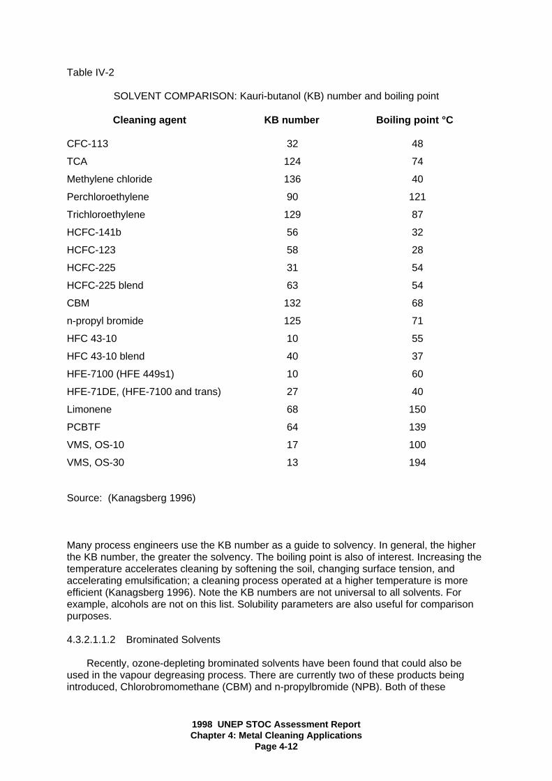
1998 UNEP STOC Assessment ReportChapter 4: Metal Cleaning Applications
Page 4-12
Table IV-2
SOLVENT COMPARISON: Kauri-butanol (KB) number and boiling point
Cleaning agent KB number Boiling point °C
CFC-113 32 48
TCA 124 74
Methylene chloride 136 40
Perchloroethylene 90 121
Trichloroethylene 129 87
HCFC-141b 56 32
HCFC-123 58 28
HCFC-225 31 54
HCFC-225 blend 63 54
CBM 132 68
n-propyl bromide 125 71
HFC 43-10 10 55
HFC 43-10 blend 40 37
HFE-7100 (HFE 449s1) 10 60
HFE-71DE, (HFE-7100 and trans) 27 40
Limonene 68 150
PCBTF 64 139
VMS, OS-10 17 100
VMS, OS-30 13 194
Source: (Kanagsberg 1996)
Many process engineers use the KB number as a guide to solvency. In general, the higherthe KB number, the greater the solvency. The boiling point is also of interest. Increasing thetemperature accelerates cleaning by softening the soil, changing surface tension, andaccelerating emulsification; a cleaning process operated at a higher temperature is moreefficient (Kanagsberg 1996). Note the KB numbers are not universal to all solvents. Forexample, alcohols are not on this list. Solubility parameters are also useful for comparisonpurposes.
4.3.2.1.1.2 Brominated Solvents
Recently, ozone-depleting brominated solvents have been found that could also beused in the vapour degreasing process. There are currently two of these products beingintroduced, Chlorobromomethane (CBM) and n-propylbromide (NPB). Both of these

1998 UNEP STOC Assessment ReportChapter 4: Metal Cleaning Applications
Page 4-13
products are very similar to 1,1,1-trichloroethane in chemical and physical properties. Theyhave boiling points slightly less than and solvency nearly the same as 1,1,1-trichloroethane,which make them possible replacements.
The STOC have recommended to the Parties of the Montreal Protocol through theTEAP that because of their ODP and other factors, a more in depth evaluation of CBM andNPB be done and consideration be given to future regulation.
NPB has recently been commercially introduced. The value for Ozone DepletionPotential available at this time puts NPB in the same range as HCFC-225. This wouldsuggest that based on ODP it might be classified equivalently. Testing to determine the toxiceffects is in process. The US EPA listed this compound as pending, also awaiting ODP andtoxicological data.
According to ISO test methods, pure NPB has a Pensky-Martens closed cup flash pointof -10°C, although it would be difficult to maintain combustion. Further information is neededfrom the producers of NPB on the flammability issue and to its suitability for use in vapourdegreasers.
There has been some uncertainty about the ODP of NPB depending on the modelingmethod used. This is now being resolved by the UNEP Scientific Advisory Committee whowill assign a value during 1998.
4.3.2.1.1.3 HCFCs and Their Blends
Hydrochlorofluorocarbon (HCFC) and their blends have ozone-depletion potentials,although these are lower than those of CFC-113. HCFC-123 and HCFC-141b havesignificantly lower boiling points (27-32 °C) than CFC-113 (48°C) or 1,1,1-trichloroethane(73 °C). This raises the possibility of increased vapour emissions from operation processes,increased fugitive emissions during material transfer, and increased handling and storagerequirements. The boiling point of HCFC-225 is 51-56°C, which is equivalent to that of CFC-113. Blends of HCFC-225 therefore could be an alternative to CFC-113. Because HCFC-225 has a relatively low solvency and good materials compability, it is particularly usefulwhere there is relatively light soil loading and where components contain both metal andplastic components. This solvent is also very good for cleaning fluorinated greases andlubricants such as Krytox. Blends and azeotropes are available that increase the usefulcleaning range of HCFC-225. HCFC-123, HCFC-141b, and HCFC-225 are VOC exempt inthe USA.
4.3.2.1.1.4 Hydrofluoroethers and Hydrofluorocarbons
The hydrofluoroethers (HFEs) and hydrofluorocarbons (HFCs) have been introducedand are used commercially. These solvents generally are less likely candidates to replace1,1,1-trichloroethane in most metal cleaning applications, but will find some substitutionwhere CFC-113 was used in metal cleaning. The boiling points of these solvents are higherthan CFC-113 but lower than 1,1,1-trichloroethane. HFCs and HFEs have very low solvency.These solvents will also be suitable as a replacement for perfluorocarbons in the "co-solventprocess" that has been introduced in recent years. In this application the HFC or HFEfunctions as an inerting agent, providing a non-flammable vapour layer over the combustiblesolvent, and a rinsing/drying agent to remove the co-solvent from the parts.
Additional solvent mixtures have been developed as blends and azeotropes that provideadditional cleaning strength for some processes.
1998 UNEP STOC Assessment ReportChapter 4: Metal Cleaning Applications
Page 4-14
The advantages of these products are listed as:
• They use a similar process to existing CFC-113 vapour degreasing• Zero ODP• Expempted as a VOC in the USA except as blends and azeotropes
Disadvantages of HFCs and HFEs include:
• They are more costly on a per kilogram basis; therefore they require retrofitting ofthe existing equipment or the purchase of modern cleaning equipment. (However,reduced consumption from the equipment retrofitting and good work practices, cankeep the cost per unit cleaned acceptably low).
• On site recycling should be used to minimise emissions, optimise solvent usage andthus minimise overall cleaning costs.
• Pure HFCs and HFEs have limited solubility for many soils; thus azeotropes orblends are needed for many applications.
• Additional compability testing may be needed in some cases, especially forazeotropes for chlorinated solvents, where data is not available for the applicationunder consideration.
• Toxicological testing for the HFCs resulted in workplace exposure levels beingrecommended for this solvent that are lower than the levels used for CFC-113 and1,1,1-trichloroethane, but higher than the levels allowed for typical non-ozonedepleting chlorinated solvents such as trichloroethylene and perchloroethylene. Theworkplace exposure levels being recommended for HFEs are lower than the levelused for CFC-113 but above the level for 1,1,1-trichloroethane.
• Additional environmental and health studies will need to be completed.• New chemicals may require extensive compatibility testing prior to acceptance.• Although much better than PFCs, GWP effects are not completely understood for
HFCs and HFEs. Nevertheless, they have a high GWP and their use is regulated inmany countries.
4.3.2.1.1.5 Brominated Solvents
Parachlorobenzotrifloride (PCBTF) has no ODP, is VOC exempt in the U.S. and is aflammable material. PCBTF is moderately priced. The solvency is between CFC-113 and1,1,1-trichloroethane. However, the toxicity and worker exposure issues mandate use inspecialised cleaning systems.
4.3.2.1.2 Hydrocarbon Solvents
Hydrocarbon solvents and their derivatives have recently been getting increased use inspecialised equipment. Low flash point cleaning systems are designed to prevent potentialflammability and explosion hazards, by purging with inert gas or other methods.
This technology has developed from the machines originally intended for using alcoholsin vapour cleaningThe choice of hydrocarbon and the ability of the equipment to evaporate the solvent fromthe parts determine the effectiveness of the cleaning. This is accomplished either by heatingthe part to evaporate the solvent, or using vacuum to evaporate the solvent from the part.
These systems allow the use of a large number of solvents such as isopropyl alcohol,cyclohexane and acetone. Various blends, azeotropes, and co-solvents are also being

1998 UNEP STOC Assessment ReportChapter 4: Metal Cleaning Applications
Page 4-15
adopted for these systems. The minimal emissions from the system address theenvironmental, safety, and cost factors associated with the chosen solvent. However,hydrocarbons are often regulated as VOCs.
Hydrocarbon solvents are all more or less toxic, especially those with a cyclic oraromatic molecular structure. Some, such as benzene, are carcinogenic or mutagenic. Thetoxicity of pure paraffinic aliphatic solvents is generally low, but the commercial grades oftencontain small quantities of aromatic solvents. Some oxygenated hydrocarbon derivatives arehighly toxic while others are less so: no general rule is therefore derivatives are highly toxicother chemicals, their toxicology is a very complex subject involving the different organs, itsfixation and accumulation in specific organs or groups of organs, its metabolisation and itselimination.
Hydrocarbons with flash points exceeding an arbitrary 50°C are classified ascombustible, rather than flammable. Provided that they are used at a maximum temperatureof about 20°c under their flash point in non-misting applications (no spraying through air orultrasonics), they may be used without other precautions. However, because such solventshave lower vapour pressures, drying may be more difficult or energy-intensive. It has beendetermined, for example, that such a solvent with a flash point of 105°c, when dried at 85°C,required drying times and energies several times those of water at the same temperature ona geometrically complex structure with capillary spaces. In some cases, it has provedeconomical to use combustible solvents at an elevated temperature for the cleaning andinitial rinse stages, especially to dissolve heavy greases: the final rinse is done with a lowflash point solvent in an inert-gas purged compartment, just to facilitate drying.
4.3.2.1.3 Volatile Methyl Siloxanes
Volatile Methyl Siloxanes (VMS) is a class of compounds, currently being offered. VMShave no ODP but are flammable. VMS are high priced but less costly than HFEs or HFCs.While the solvency is low for most soils of interest it is good for silicone based oils. Variousblends, azeotropes, and co-solvent systems increase the useful cleaning range of thesesolvents. The flow flash point of these compounds requires the use of specialisedequipment.
4.3.2.2 Manual Cleaning
For manual cleaning, a number of commercial solvent blends are available. Theseproducts are mixtures of aliphatic and oxygenated hydrocarbon solvents (e.g., ketones,ethers, esters, and alcohols). All degreasing solvents and the organic constituents of blendsare volatile and many are flammable. Such solvents or blends may require control measuresin accordance with local, regional, or federal regulations or with corporate policies governingtheir use. These control measures address concerns over environmental, health, and safetyissues.
The newer blends being developed are optimised for maximum soil removal, minimumflammability and toxicity, and low composite vapour pressure/evaporation rate. Theseblends are viable substitutes for 1,1,1-trichloroethane and CFC-113 in situations wherevolatile organic compounds can be controlled or are not regulated.

1998 UNEP STOC Assessment ReportChapter 4: Metal Cleaning Applications
Page 4-16
4.3.2.3 Cold Immersion Cleaning
Solvent blends of aliphatic naphtha, certain terpenes, and dibasic esters are commonlyused in immersion cleaning of heavy soils and greases in industrial maintenance operations.These blends are viable substitutes for 1,1,1-trichloroethane and CFC-113 where possiblehydrocarbon residue from the high molecular weight fraction of the naphtha does not poseproblems and volatile organic compounds can either be controlled or are not regulated.Depending on the formulation and if carried out; subsequent water rinsing may produce amixed waste stream which may pose potential water pollution problems. Some of the newerblends being marketed have equal cleaning capacity to those that contain halogenatedsolvents. These include high flash point aliphatic naphthas, blends of aliphatic naphthas withterpenes or esters, and hydrocarbon/surfactant blends.
HCFC-225 is another alternative that is commercially available for use in cold cleaningapplications. It has been demonstrated that the degreasing ability of HCFC-225 iscomparable to CFC-113 for cold immersion cleaning, thereby making it a suitablealternative. HCFC-225 is also used as an alternative to cold cleaning with1,1,1-trichloroethane. However, because the degreasing ability of HCFC-225 is far less than1,1,1-trichloroethane this is not as common (see Table IV-2). HCFC-225 is regulated underthe Montreal Protocol as a transitory substance.
Many of the alternative solvents can be used for cold immersion cleaning. However,most should be used in systems that maximise vapour containment and minimise workerexposure.
4.3.3 Aqueous Cleaners
4.3.3.1 Cleaner Formulations
Aqueous cleaners are a viable, broad substitute for CFC-113 and 1,1,1-trichloroethaneused in degreasing metals. Aqeous cleaners are comprised of three major types ofcomponents:
• builders - alkaline salts such as sodium tripolyphosphate, sodium silicate, or sodiumhydroxide which make up the largest fraction of the cleaner.
• surfactants - organic compounds such as alkyl benzene sulfonates or
polyethoxylated high molecular weight alcohols that serve as wetting and emulsifyingagents and thus are the principal source of the detersive properties of the cleaner(octyl- and non-ethylated detergents are to be avoided where possible. Theybiodegrade readily but in doing so, produce by-products which are extremely stableand toxic to aquatic life).
• additives - organic or inorganic compounds such as the ethanolamines that saponifyvegetable and animal greases or sodium citrate and the disodium salt of EDTA orsodium citrate that serve as chelating or sequestering agents for softening water orbinding with undesirable metal ions in solution. Corrosion inhibitors are also added tominimise the effect of the aqueous cleaners on the metal surface 3. Numeroushandbooks and technical references are available and provide a comprehensiveexplanation of aquous cleaner chemistry and performance (Linford 1950, Spring1974, U.S. EPA 1991a).
--------------------------------------------------------------3 Silicate salts are typical corrosion inhibitors and prevent alkaline attack on soft metals such as aluminium andzinc. Other additions include anti-oxidants, such as amine borates, stabilisers, and small amounts of water-miscible solvents, such as some glycol ethers.

1998 UNEP STOC Assessment ReportChapter 4: Metal Cleaning Applications
Page 4-17
Alkaline cleaners are effective in situations where a broad spectrum of soils are presentand a variety of substrate materials are being cleaned. Hundreds of alkaline cleaningformulations are commercially available and more are currently under development. Theseproducts should be screened for specific applications to ensure that they meet the soilremoval requirements, are compatible with substrate materials, and do not leave residuesharmful to the surface or downstream surface coating processes. Alkaline cleaners shouldbe carefully evaluated when used with amphoteric metals, such as magnesium, aluminium,zinc etc. or alloys containing them.
Acidic cleaners 4 are used to remove rust and scale which cannot be removed byorganic solvents. They are also used to clean aluminium; a metal susceptible to etchingwhen cleaned with strong alkaline cleaners. In general, acidic cleaners cannot be used assubstitutes in organic cleaning applications.
4.3.3.2 Aqueous Cleaning Processes
The principal stages in aquous cleaning are washing, rinsing, and drying (See FigureIV-3). Thermal (temperature), chemical (concentration), and mechanical (agitation) energiesinfluence soil removal. These can be optimised for specific cases. Mechanically energy inwashing and rinsing can be provided through ultrasonics, immersion with agitation of thecleaning solution or of the parts, and spraying. Aqueous cleaning equipment can becharacterised as either in-line equipment, used for high throughput cleaning requirements,or batch equipment used for low and medium throughput such as maintenance applicationsor smaller production processes. In-line and batch equipment can be further subdivided intosummersion spray, and ultrasonic equipment. Equipment design features and options vary.Options include solution heaters, dryers, parts handling automation equipment, in-processsolution filtration, and solution recycle and treatment equipment. Immersion cleaning,ultrasonic cleaning, and spray cleaning processes are described below.
4.3.3.2.1 Immersion Cleaning
Aqueous immersion cleaning combines chemical, thermal, and mechanical energies.Immersion cleaning consists of four major steps: cleaning, rinsing drying, and wastewatertreatment (recycling or disposal).
In the cleaning process, the parts are immersed in a solution and some form of agitationis added to provide the mechanical energy needed to displace, dissolve, saponify, andemulsify soils. The cleaned parts are usually rinsed with deionised or relatively pure water.Additives may be added to enhance wash solution displacement and decrease the amountof water drag-out or prevent flash rusting prior to drying.
--------------------------------------------------------------
4 Acidic cleaners contain mineral (hydrochloric, nitric, sulphuric, phosphoric, hydrofluoric, or chromic etc). ororganic (acetit or oxalic etc.) acids plus detergents, chelating agents, and small amounts of water-misciblesolvents.

1998 UNEP STOC Assessment ReportChapter 4: Metal Cleaning Applications
Page 4-18
Rinsing removes any remaining contaminants and cleaning solution dragout and mayserve as a final cleaning step. Rinsing is an essential step in most aqueous cleaningapplications. Care should be taken to prevent cleaning fluids from being trapped in holesand capillary spaces. Low surface tension cleaners sometimes penetrate spaces and arenot easily displaced by higher surface tension rinse water. Drying helps prevent surfaceoxide formation, eliminates potential corrosion caused by solution penetration between closetolerance surfaces, and dries parts for further manufacturing activities 5. Drying can be amajor challenge in aqueous cleaning. It is typically the rate-limiting step in aqueousprocesses and is often given inadequate consideration in process design. In the case ofsimple geometric or flat surfaces, the challenges may be minimal, but for complex parts,rinsing and drying may require considerable engineering analysis and experimentation. Acombination of mechanical methods and multiple operations may be requires to displace thecleaning solution from the surfaces of a geometrically complex part.
From the perspective of energy or process time, evaporation removal of bulk water isusually not practical. Compact turbine blowers, in conjunction with adequately designedair-jets or air-knives, with filtered output can mechanically remove 90 percent or more of thewater. Care must be taken to assure desired air quality by appropriate filtration of oil,particulates, and moisture. Noise reduction, humidity, and air conditioning control are otherconsiderations. Conventional convection or forced air ovens can be used for drying but areenergy-intensive, as are all evaporation processes. For certain lower temperature dryingrequirements, vacuum dryers can be custom designed and fabricated but also require muchenergy to ensure thorough evaporation. They should be designed with cryogenic traps toensure that the water vapour does not enter the vacuum pump, where it could causedeterioration of the lubrication. Traps also keep lubricating oil vapours from refluxing into thevacuum oven.
The simplest aqueous immersion cleaning machine configuration consists of a singlewash tank. This may be adequate to remove gross soluble cutting oil residues where theparts will receive further processing. The demands of most cleaning jobs, however, will likelyrequire more complex equipment configurations. If a part must be cleaned to a high degreeof cleanliness or if the quality of downstream process solutions is a great concern, severalwash and rinse stages would be required.
-------------------------------------------------------5 Some manufacturing processes require dried parts; others such as many metal finishing process lines(anodising or electroplating) do not.
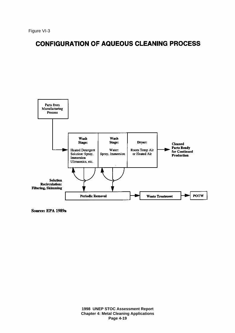
1998 UNEP STOC Assessment ReportChapter 4: Metal Cleaning Applications
Page 4-19
Figure VI-3

1998 UNEP STOC Assessment ReportChapter 4: Metal Cleaning Applications
Page 4-20
4.3.3.2.2 Ultrasonic Cleaning
Ultrasonic cleaning effectively cleans intricate parts and contaminants such as carbonand buffing compounds that are difficult to remove (Randall 1988a, Oakite 1988). Ultrasonicmachines are appropriate for cleaning small, parts.
Ultrasonic cleaning equipment creates submicron-sized vacuum cavities at the metalsurface by vibrating the cleaning solution at high frequencies. As the cavities form andcollapse, they create a scrubbing action that cleans the entire surface of the parts, includingblind holes and very small cracks and recesses (Unique Industries 1988). This cavitationprocess creates extremely high temperatures and turbulence on a microscopic scale.Transducers vibrate the tank (and hence the cleaning solution) at frequencies usually in therange of 25 kHz to 40 kHz (Branson 1988).6
Gross contamination of parts may reduce the effectiveness of ultrasonic cleaning.These contaminants are most effectively removed in a heated immersion tank with agitatedcleaning solution or in a spray washer (Randall 1988b). Based on research performed bythe U.S. Air Force, it has been determined that ultrasonic cleaning enhances the corrosivityof the solvents. Process design requires caution to ensure that the ultrasonics doe notcause and metal surface corrosion or damage to the parts. It also uses relatively largeamounts of electricity compared to agitation immersion cleaners of similar size (Racquet1988). Aqueous ultrasonic cleaning equipment can be configured with other cleaning stagesfeaturing parts and/or fluid agitation, or it may be used as one step in a spray machine. Inaqueous systems, it is essential to degas the cleaning solutions and rinse water to obtainoptimum results. The ultrasonic/spray combination is more common for solvent-basedequipment than for aqueous equipment.
4.3.3.2.3 Spray Cleaning
Spray equipment cleans parts with spray pressure and volume which may be variedgreatly depending upon the application. Depending upon the resilience of the surface to becleaned, spray equipment can be used to physically displace many soils. In general, thehigher the spray force, the more mechanical energy is provided in removing soil from metalsurfaces. Spray cleaners incorporate low-foaming detergents, which are not always aschemically or physically energetic, as those used in immersion cleaners but are enhancedby the mechanical agitation. Spray cleaning is effective on flat surfaces and those made upof simple geometric parts.
One difference in spray cleaning equipment is the way in which each generatesmechanical energy to clean parts. While the mechanical action of spray cleaning equipmentis spray action, the mechanical action of an immersion machine may be created byultrasonic waves, vertical agitation of parts, or bath turbulence. A custom spray machine cancombine spray action with the mechanical action used in immersion equipment. Optimisationof nozzle design such as spray pattern, drop size and formation, pressure/velocity, andvolume are very important and have a major impact on both wash and rinse effectiveness.Different configurations are usually required for washing and rinsing. Spray rinsing uses lesswater and can provide cleaner surfaces than an immersion bath, since the final water, whichcontacts the part, can be quite pure.
--------------------------------------------------6 1 kHz equals 1,000 vibrations per second.

1998 UNEP STOC Assessment ReportChapter 4: Metal Cleaning Applications
Page 4-21
The major differences among spray machines, however, relate to the manner in whichthe parts are handled. Spray washers are of three general types: batch, conveyor, androtary.
4.3.3.2.3.1 Batch Spray Equipment
Batch spray cleaning equipment consists of a tank to hold the cleaning solution and aspray chamber with a door. Although batch spray machines have a single spray chamber, itis possible to rinse parts in the same chamber by using a separate set of "plumbing"equipment to spray water on the parts. The rinse water is then channelled away from thetank holding the cleaning solution (Kelly 1988). These chambers can be manual orautomated.
Batch spray machines can be used for maintenance or manufacturing applications, butgenerally do not clean as thoroughly as multiple stage machines, unless they are alsoptimised for washing and rinsing. Batch machines are generally more flexible than othertypes as the time/temperature characteristics for each part of the operation can beindividually regulated.Because maintenance applications tend to have lower throughput requirements thanmanufacturing applications, batch spray machines often are used for maintenance cleaning.For precleaning of heavy soils, large cabinet wash and rinse chambers with spray nozzleslocated around the perimeter are available and have been designed to accommodateobjects as large as electric motors and engines of trains. For removal of heavy greases andtars, high-pressure steam is an excellent medium for precleaning and, for some equipmentmaintenance activities, will provide acceptable cleanliness. This approach has theadvantage that the soil and condensate will rapidly separate into water and oil phases.
4.3.3.2.3.2 Conveyorised Spray Equipment
Conveyorised spray cleaning equipment consists of a tank to hold the cleaning solution,a spray chamber, and a conveyor to feed parts through the machine. A more complexconveyorised system includes multiple wash and/or rinse stages along the conveyor, eachstage with its own tank. The rinse water may be recirculated, especially if it contains atreatment chemical such as a rust inhibitor. The rinse water may be appropriatelydischarged if throughput is high or if parts drag significant quantities of cleaning solution outof the wash stages.
Conveyorised equipment is usually used in manufacturing applications with highthroughput requirements where have flat, even, controlled surfaces. The advantages ofconveyorised equipment are high throughput and automated parts handling. If parts areprocessed before cleaning so that they may be handled automatically from a processconveyor, it may be unnessessary to manually handle the parts during cleaning.Conveyorised spray washers can clean all sizes of parts from a variety of industries. Thisapproach reduces the amount of wastewater generated as compared to immersion cleaningand rinsing. For small parts with uneven and curved surfaces that may not be readilycleaned with immersion and agitation, dishwasher-type units with rotating parts holders andmulti-directional spray nozzles are available.
4.3.3.2.3.3 Rotary Spray Equipment
Rotary spray equipment is very similar to conveyorised spray equipment except for themanner in which parts are handled. A rotary machine employs a steel drum with a partition

1998 UNEP STOC Assessment ReportChapter 4: Metal Cleaning Applications
Page 4-22
that spirals along the inner surface of the drum such that when the drum is rotating, partswill be transported along the length of the drum. The drum is perforated so the spray canimpinge on the parts to be cleaned.
Rotary spray washers are designed to clean small parts such as screw machine parts(e.g., nuts and bolts) and small metal stampings. Rotary equipment can clean large columesof parts, but the parts must be able to withstand the tumbling action of the rotating drum.Parts with delicate outer diameter threads and polished parts that should not be scratchedshould be cleaned in a different type of machine using a basket with a locking lid that canhold the parts in place during cleaning (Taylor 1988). High throughput can be achieved withthese machines, making them good candidates for high volume manufacturing operations.One trade-off, however, is that the rotary machines require more energy input than othertypes of spray machines.
4.3.4 Hydrocarbon/surfactant ("Semi-aqueous" and “Emulsion") Cleaners
Hydrocarbon/surfactant (HCS) blends are emulsion cleaners that have been developed,tested extensively and are beginning to be used as substitutes for CFC-113 and 1,1,1-trichloroethane in metal cleaning applications which incorporate high viscosity and highmolecular weight soils, semi-solid soils, and corrosion sensitive substrates. HCSs areincluded in many different cleaners and are formulated for different purposes. Examples ofthese families of chemicals are the terpene hydrocarbons and glycol ethers.
HCSs are used in cleaning processes in two ways. They are either emulsified/diluted inwater and applied in a manner similar to standard aqueous cleaners or they are applied in aconcentrated form and the rinsed with water. Because both methods use water in thecleaning process, the hydrocarbon/surfactant-based process is commonly referred to as asemi-aqueous process.
The benefits of HCS cleaning processes include the following:
• Good cleaning ability (especially for heavy grease, tar, waxes, and hard to removesoils)
• Many HCS cleaners are compatible with most metals and plastics• Suppressed vapour pressure (especially if used in emulsified form)• Nonalkalinity of process reduces corrosion potential and reduces the metal content
of wastestreams• Reduced evaporative loss• Potential decrease in solvent consumption that may lower overall cost• Ability of some formulas to separate easily from water
The drawbacks include:
• Recycling or disposal cost of wastewater could make the process less economicallyviable
• Flammability concerns if concentrated cleaner is used in spray cleaners• Special equipment designs may be needed to account for flammability• Objectionable odours with many cleaners• VOCs are major components of some cleaners• Drying equipment will be required in most applications• Drying time• Gelling of some cleaners in low water-content emulsions• Difficulty in reducing surfactants used in cleaners

1998 UNEP STOC Assessment ReportChapter 4: Metal Cleaning Applications
Page 4-23
• Toxicity considerations not yet defined for all cleaners• Auto-oxidization of some cleaners. For example, d-limonene (a type of terpene) can
auto-oxidize. The terpene suffers auto-oxidation naturally from contact with air. Thiscan in some instances be reduced using antioxidant additive
• HCS cleaning systems will require more floor space than a traditional solvent system• Capital cost of equipment may be high because of the combining of both solvent and
aqueous cleaning• Energy consumption may be higher than that of solvent cleaning systems in
applications that require heated rinse and drying stages• In some applications, high purity water, which is expensive, may be needed• Dragout and carryover of cleaning agent• Thorough water rinsing is required• Waste treatment may be complicated and expensive
The steps in a typical HCS cleaning process are analogous to aqueous cleaning (seeFigure IV-4). Equipment for use with HCS processes are modifications of aqueous cleaningequipment design with the addition of extra tanks, chambers and pumps to handle thesolvent cleaning phase.
Dilute hydrocarbon emulsion cleaners formulated with water may be heated. Lessmechanical energy is needed when using a HCS solution than when using an aqueoussolution because of the high solvency of HCS cleaners. Rinsing with clean water removesthe residues left by the wash step.
Equipment for use specifically with concentrated HCSs is available. As with aqueouscleaning, this can be classified as immersion or spray equipment and as either batch orin-line equipment. Because of the solvency of HCSs, less mechanical energy is requiredthan in aqueous cleaning to achieve adequate cleanliness. Emulsion cleaners alsoeffectively clean metal parts using ultrasonics.
Because of the flammability concerns with spraying combustible HCS solvents throughair, it is more usual to use "under-surface" spraying. It requires high pump powers to obtainsufficient agitation to dislodge adherent soil, especially in large installations. The kineticenergy imparted to the solution is dissipated within it in the form of heat, causing atemperature rise. With solvents with a relatively low flash point (e.g. under 100°C), thistemperature rise may be sufficient to approach the solvent flash point. In this case, coolingmay be required to maintain the solvent temperature at a safe level.
4.3.5 Miscellaneous Alternatives
4.3.5.1 Mechanical Cleaning
Various mechanical cleaning methods have been used for metal surface preparationand proposed as possible alternatives for CFC-113 and 1,1,1-trichloroethane. Brushing,wiping with rags or sponges, use of absorbent materials, media blasting and pressurisedgages are being investigated to various degrees. These methods, however, are generallybest suited for lower grade cleaning requirements or as a pre-cleaning operation in theremoval of solid and semi-solid soils.
Pressurised gas may be used in some cases for particulate contamination as analternative to cleaning with 1,1,1-trichloroethane and CFC-113. Gases that may be usedinclude air, rare earth gases, carbon dioxide, and nitrogen. These gases are readilyavailable in bulk and smaller quantities and in numerous grades of purity. The advantages of

1998 UNEP STOC Assessment ReportChapter 4: Metal Cleaning Applications
Page 4-24
cleaning with pressurised gases versus 1,1,1-trichloroethane include the following. lowviscosity, low toxicity, high diffusivity, nonflammability, and low capital cost. Disadvantagesof using pressurised gas include: low density, high pressure, cleaning of criticalcomponents, and often ineffectiveness in cleaning microscopic particles.
Compressed air typically found in workshops is totally unsuited for this applicationbecause it is frequently heavily contaminated with oil (from the compressor), water(condensate from the adiabatic compression of humid air) and rust particles (from theconduit pipes). Experience has shown that filtering shop air to remove these contaminants isnot easy and requires constant maintenance of the filters. If this is the only option, it isrecommended that the compressor be fitted with suitable refrigerated filters and that eachwork station be fitted with an additional set of filters. For example, a mechanical filter (say 1micrometre), an oil sedimentation filter and a colour-indicated silica-gel drying filter may beused.
Specific technologies under development include wheat starch, sodium bicarbonate,and solid carbon dioxide blasting. Wheat starch can be dissolved in rinse water for disposaland is not considered a hazardous waste after the oils and greases are skimmed off. Thecarbon dioxide evaporates after cleaning leaving the oil and grease contaminates behind,thereby reducing the volume of waste generated. Carbon dioxide blasting is currently beingused for paint stripping but may be too forceful for less problematic cleaning needs (KellyAFB).
4.3.5.2 Thermal Vacuum De-oiling
Thermal vacuum de-oiling is a system that uses a heated vacuum chamber to removeoil from parts by vaporising the oil. The vapours are then pumped through a cold trap wherethey are condensed and drained from the system for recycle or disposal. Typical cleaningapplications for vacuum de-oiling are parts of either simple or complex design that are soiledwith low- to mid-viscosity oils. This technology can be used to successfully clean partsfollowing cutting, machining, quenching, and stamping operations. Vacuum de-oiling is alsoused to clean parts in preparation for brazing, coating, plating, and heat treating operations.
Advantages of vacuum de-oiling include the following: elimination of cleaning solvents,provision of ultraclean parts, simple operation of equipment, reclamation of oils, floor spacerequirements similar so that of vapour degreaser equipment, and generally no need forenvironmental permits. The primary disadvantge of vacuum cleaning is that the system isvery soil specific. Vacuum cleaning is only capable of removing oils that can be volatilisedwithin certain temperature, time, and pressure ranges. The equipment settings for thesevariables depend on the characteristics of the oil being removed as well as the mass andsurface area of the parts being cleaned. For these reasons vacuum cleaning systems workbest in manufacturing applications that have consistent part size and soil loading. Capitaland running costs may be quite high.
4.3.5.3 Liquid Carbon Dioxide Cleaning
Liquid carbon dioxide is a very effective degreasing solvent that poses minimalenvironment impact. Until recently, the cost of the necessary equipment has been high andthe throughput potential is low. New innovations in both the carbon dioxide chemistry andmore effective, but still costly, equipment are bringing liquid carbon dioxide cleaning mustcloser to routine use. For the moment it only makes economical sense in high value added

1998 UNEP STOC Assessment ReportChapter 4: Metal Cleaning Applications
Page 4-25
cleaning such as precision cleaning. Liquid carbon dioxide cleaning machines are now beingintroduced into the dry cleaning industry.
4.3.5.4 Xenon Flashlamp
In 1990 a team of engineers from the McDonnell Douglas Corporation, Cold Jet Inc.,and Maxwell Laboratories Inc. developed the FLASHJET coatings removal process. TheFLASHJET process combines a xenon-flashlamp with low pressure carbon dioxide (dryice) pellet blasting. The xenon flashlamp ablates the coating off the substrate and dry icepellets cool and clean the substrate while sweeping away the coating into an effluentcapture system. The effluent capture system vacuums the coatings into High EfficiencyParticulate Air (HEPA) filters that are then disposed of accordingly. The U.S. Navy hasrecently approved the process on metallic fixed wing aircraft. The U.S. armed services arealso evaluating this process for a number of other aircraft and ground based vehicles.
Using the FLASHJET technology as a primary removal process can lead to anestamined 70% reduction in wastes over traditional depainting processes. Current estimatedoperating life cycle costs are calculated to be approximately $4 (U.S.) per square foot. Theoperator is located outside the stripping cell and is not exposed to any effluent as andharmfull gases during the ablation as the process is fully automated. (P. Stemniski, 1998).
4.3.6. Reducing the Need to Metal Clean
A number of volatile machining oils and forming lubricants are currently available toproduce metallic parts without vacuum system or cleaning processes. For example, a heatexchanger of a domestic air-conditioning unit has been made by aluminium fins and coppertubes with many kinds of machining oils and forming lubricants. Traditionally, large amountsof 1,1,1-trichloroethane have been used for removing these oils. Volatile oils and lubricantsare VOCs and recovcery of the vapours becomes necessary in most places. The use ofvolatile oils may also impose a change in the flow of parts through a plant. For example, ifrefrigerator side and door panels are being formed with a volatile drawing lubricant, theymay require to spend one or two days in a drying sector before passing onto the paint shop.
A number of water-soluble and emulsifiable machining and metal forming lubricants areavailable. These products are easier to clean using aqueous or semi-aqueous cleaners andare less of a concern for worker exposure. Hot water immersion, spray, or hot waterimmersion with ultrasonics may be sufficient for removing lubricants that contain emulsifiers.Lubricant spray applicators which discharge a fine well-controlled mist can decreaselubricant usage without affecting product quality. Other alternative lubricants underdevelopment include "dry" lubricants and thin polymer sheeting which can be peeled fromthe surface after the metal forming operation, or in the case of tube forming, "empty tubebending" which accomplishes the forming operation without the use of a lubricant. Theseproducts and methods are not standard industrial practices. They do, however, offer thepotential for eliminating the need for degreasing.

1998 UNEP STOC Assessment ReportChapter 4: Metal Cleaning Applications
Page 4-26
Figure IV-4

1998 UNEP STOC Assessment ReportChapter 4: Metal Cleaning Applications
Page 4-27
Material flow through production should also be reassessed to minimise the number oftimes that a part is degreased and to consolidate the cleaning operations into a centralisedunit or location. In many plants, parts are degreased two and possibly three times beforefinishing and assembly. Consolidation of cleaning operations will decrease the amount ofsolution used and waste generated.
Segregation and pre-cleaning of heavily soiled parts can extend bath life. Heavily soiledparts can also be routed separately through a single pre-cleaning system; this has the effectof decreasing the amount of contaminated cleaner being generated in the main productionarea cleaning systems, because the amount of soil entering these systems is minimised.Absorbent methods (absorbent laden pads or cloths) can be used to wipe clean parts andsurfaces after initial fabrication, thereby reducing the final cleaning requirements.
4.3.7 CFC-113 and 1,1,1-Trichloroethane Processes for Which Alternatives are NotAavailable
Alternatives are currently available for virtually all metal cleaning processes thatpreviously used CFC-113 and 1,1,1-trichloroethane. Those applications for which there is nocurrently available alternative can be put into two groups. First, there are those applicationsfor which the Parties to the Montreal Protocol have granted an Essential Use Exemption(EUE). In granting these exemptions, the Parties recognise that there are no feasiblealternatives to the use of CFC-113 and 1,1,1-trichloroethane in the short term. The secondgroup is comprised of some applications for which stockpiling or recycling ofCFC-113 and 1,1,1-trichloroethane is to be used to satisfy short-term demand for thesesolvents.
4.4 CARBON TETRACHLORIDE USE, REDUCTION ANDREPLACEMENT
Previous versions of this report (1988, 1992, 1994) indicated that carbon tetrachloride(CTC) was primarily used for non-dispersive uses with only small amounts used as afumigant in Montreal Protocol Article 5(1) (developing) nations. Since 1994 it has beenfound that there is significant use (possibly up to 10,000 tonnes) of this substance in variouscleaning processes in developing countries. Because of its low cost and good degreasingproperties, CTC is widely used. Typically it is used in simple open containers where itpresents not only a serious threat to the ozone layer but because of its proven toxic effects,a threat to the health of the workers. The problem is made more difficult because of thelarge numbers of small users using this form of cleaning with minimal resources for change.Nevertheless, cleaning with CTC in open baths should not be allowed to continue.
CTC uses have been identified primarily where a low cost, non-flammable, and simplecleaning process is required, such as metal cleaning applications. Initially, immediatesubstitution of trichloroethylene, or perchloroethylene may seem warranted. However, thereare other environmental, safety and helath issues that also need to be balanced. Such achange would most likely offer improved working conditions, but other practices such aswaste disposal and possible water contamination should also be considered when changingto any new alternative.
All solvents need some form of ventilation when used for manual cleaning and thisshould be a prerequisite for change. Alternative solvents that could be used are low flashpoint hydrocarbons, provided suitable precautions are taken during storage.

1998 UNEP STOC Assessment ReportChapter 4: Metal Cleaning Applications
Page 4-28
It should be noted that following the phase out 1,1,1-trichloroethane in developedcountries, specially formulated solvent blends became a popular alternative for coldcleaning. Experience has shown that labels and technical data sheets, which are impreciseor unlclear, can lead to higher risks in terms of safety due to flammability. Initiatives byformulators to describe precisely this risk have taken place in developed countries andshould be encouraged world wide for cold cleaning substitutions.
Countries where CTC is currently being used in cleaning processes need to developlong-term plans and the infrastructure to assist users with the proper methods of use anddisposal of any alternative. For the implementation of alternative cleaning processes thisincludes, good chemical management of all cleaning chemicals, proper work training on useand disposal of chemicals, and an infrastructure for the safe and environmentally correctdisposal of wastes.
For aqueous cleaning systems, this means the availability of usable water and the safedisposal of wastewater to an acceptable treatment facility. For solvent cleaning system,recycling and disposal programs need to be implemented. For the most part the solventwastes can be sufficiently recycled such that the resulting waste can be used in fuelblending programs for approved cement kilns. Efforts to establish the outlet for usefuldestruction of the cleaning wastes should be a high priority for developing countries.
4.5 COST OF ALTERNATIVES
Due to the wide variety of alternatives available to replace CFC-113 and1,1,1-trichloroethane in metal cleaning applications, a full discussion of the costs of thesealternatives is not practical. However, there are several universal cost components thatshould be considered when evaluating alternative cleaners or cleaning technologies. Thesecost components can be split into two groups -. one-time costs and recurring costs.
One-time costs are those costs that are incurred only at the beginning of a project andare not repeated throughout the project life. The most significant of these costs is often thecapital investment of new equipment or in the retrofit of existing equipment. Other one-timecosts may include items such as laboratory and production testing. environmental, health,and safety impact studies, equipment installation, process control means and methods,personnel training, documentation revisions, and environmental permitting or licensing.
Recurring costs are primarily operating costs. These costs are incurred throughout thelifetime of the equipment or cleaning process and are often calculated on an annual basisand compared to the costs of the CFC-113 or 1,1,1-trichloroethane cleaning process.Recurring costs may include costs for raw materials (cleaning detergents, solvents, water),water purification, energy usage, recycling, waste treatment/disposal, and equipmentmaintenance.
4.6 ENVIRONMENTAL, HEALTH, AND SAFETY CONSIDERATIONS
This document is not a risk assessment and therefore it contains only a generaldescription of some of the environmental health and safety issues associated with eachalternative cleaner or cleaning technology. The health and environmental effects of some ofthese technical options are still being investigated. Certain commercial solvents aregenerally recognised as toxic while others are suspected but not confirmed as toxic. Othercleaners including aqueous and emulsion cleaners contain constituents which may behazardous or which can have adverse environmental effects if discharged. Nonetheless, theuse of toxic chemicals is permitted in certain cases by governmental authorities but usually

1998 UNEP STOC Assessment ReportChapter 4: Metal Cleaning Applications
Page 4-29
require strict workplace controls and effective waste treatment and/or disposal. However,regulations may vary depending on location. In some circumstances it may be prudent toselect cleaning options that do not depend as heavily on workplace controls and wastetreatment.
The environmental, health and safety impacts on the alternative compounds that couldbe used in cleaning applications must be evaluated prior to their use. These impacts mayinclude: acute and chronic health effects, ozone-depleting potential, flammability, aquatictoxicity, global warming potential, and volatile organic compound (VOC) classification.Potential users of alternative cleaners should be aware of the acceptability of a particularalternative in their country, region, and locality. Users should consult local, regional, andnational regulations governing the use, emission, or disposal of any solvent cleaner. TheSolvents, Coatings and Adhesives Technical Options Committee or its individual membersdo not endorse the worker safety or environmental acceptability of any of the technicaloptions discussed.
4.7 POTENTIAL GLOBAL REDUCTION OF OZONE-DEPLETINGSOLVENTS
The Committee consensus is that most CFC-113 and 1,1,1-trichloroethane used inmetal cleaning applications can be replaced by these alternatives in accordance with theMontreal Protocol or earlier. The majority of the short-term reduction of CFC-113 and1,1,1-trichloroethane usage is expected to be achieved through aqueous cleaningsubstitution.
For general degreasing of metal surfaces and parts, aqueous immersion cleaners andsolvent emulsions can be substituted for many metal cleaning applications. Substitutionshave already taken place in the developed countries and are underway in developingcountries. Sophisticated aqueous cleaning systems or alternative solvent systems canreplace the remaining complex cleaning applications. These complex cleaning applicationswill require extensive research and design efforts. It is important to allow for the appropriatedevelopment time to be sure that inappropriate choices that might have significant health,safety, or environmental impacts, are not made.
More than 60 percent of 1,1,1-trichlororethane was used by small manufacturingcompanies. The technical and economic impacts are critical to the survival of suchcompanies. They often lack the resources and technical capabilities of larger firms, andessentially must rely on the experience of the larger companies to transfer to the smallerfirms. This would most likely mean the smaller companies would be about two years behindthe larger firms in their phaseout. The critical needs for smaller firms to make thechangeovers are: qualification of and transition to new processes, floor space requirements,capital cost and in many cases water treatment technology.
One of the major remaining problems is that of reducing the use of carbon tetrachloridefor solvent use in Art. 5(1) nations. This solvent is the most potent of all ozone-depletingsolvents and it is probable that the worldwide annual use of it as a solvent exceeds10,000 OD tonnes.

1998 UNEP STOC Assessment ReportChapter 4: Metal Cleaning Applications
Page 4-30
4.8 SUITABILITY OF ALTERNATIVES FOR ARTICLE 5(1)(DEVELOPING) COUNTRIES AND SMALL QUANTITY USERS
Developing countries should be able to closely follow the same scenario as the smallercompanies in the developed countries. They may have an additional lag time in their ownsmaller industries. Each developing country will have somewhat different scenariosdepending upon their unique industry basis.
Developing nations that maintain joint ventures with developed countries, or with astrong multinational company-based manufacturing base will be able to incorporate newtechnology fairly rapidly. Many multinational companies plan to transfer their technology asexpendiently as possible to their operations in developing countries. However, there willneed to be a significant time lag in this technology transfer process as well. It is expectedthat most multinational companies, including jointly owned affiliate companies should beable to transition their developing country operations within two years of their homeoperations.
Potentional alternatives discussed in this chapter, as well as emerging and developingtechnologies, will be able to substitute for CFC-113 and 1,1,1-trichloroethane use in allapplications, but especially for 1,1,1-trichloroethane in metal cleaning applications.

1998 UNEP STOC Assessment ReportChapter 5: Dry Cleaning Industry
Page 5-1
CHAPTER 5DRY CLEANING INDUSTRY
5.0 SUMMARY
Major reductions in CFC-113 and 1,1,1-trichloroethane usage in dry cleaning hasresulted from the replacement of cleaning machines designed for use with these solvents.Machines using perchloroethylene or hydrocarbon solvents are the logical choices forreplacement depending on the required solvency power.
1,1,1-Trichloroethane use in dry cleaning has all but ceased. Tail end use of CFC-113will continue until private stockpiles are exhausted. Purchase of new supplies of CFC-113 isincreasingly unviable and is only continuing short-term whilst small businesses decide onreinvestment in new equipment or closure.
Recycling and recovery technology is already at an advanced stage however optimumsolvent mileage from dry cleaning machines can be achieved by improved operatorpractices and better engineering maintenance and controls. The solvent reduction benefitsfrom centralized facilities may be more fully realized with perchloroethylene or the otheralternatives described as companies replace machines using CFC-113 and1,1,1-trichloroethane.
The Committee consensus is that CFC-113 or 1,1,1-trichloroethane is no longernecessary for dry cleaning in development countries. CFC-113 and1,1,1-trichloroethane use can be eliminated through the use of currently available alternativesolvents, such as perchloroethylene and hydrocarbon. Whilst work continues to modifyinternational care labelling agreements, the Committee advises clothing manufacturers toensure that fabrics, trimmings, and interlinings are suitable for dry cleaning inperchloroethylene.
5.1 INTRODUCTION
Dry cleaning enables the cleansing and reuse of fabrics that cannot be cleaned byalternative methods. The inherent environmental friendliness of restoring freshness to soiledarticles and garments is matched by extreme efficiency in terms of solvent and energy usein the dry cleaning process itself. Organic solvents are used to clean fabrics because, unlikewater, they do not distort some natural and synthetic fibres. Water cleaning of manymaterials can affect the stability of fabric, lining, and interlining and may cause stretching orshrinkage.
In addition to the actual machine cycle, the term "dry cleaning" includes a large numberof operations: customer service, precleaning stain treatment/heavy soil release, post-cleaning stain treatment, tailoring, pressing and ironing. In such a labour-intensive business,where up to 40 percent of receipts are required for wages alone, dry cleaners have hadstrong financial incentive to pay close attention to other operating costs, including solventcost/selling price ratio. Even before the ozone depletion contribution of solvents becamewidely known, dry cleaners, for purely commercial reasons, had been frugal solvent users.This scenario has had two other effects: low solvent use/high energy efficiency has been animportant factor in the purchase of dry cleaning machines, and manufacturers havecompeted to produce and market increasingly efficient and environmentally acceptableproducts.

1998 UNEP STOC Assessment ReportChapter 5: Dry Cleaning Industry
Page 5-2
For many years, dry cleaning machines have been totally enclosed; incorporatingfiltration distillation, and refrigerated recovery systems allowing solvents to be continuouslyrecycled. The technology developed by some European dry cleaning machinemanufacturers has led to the manufacture of metal cleaning machines with similar highsolvent efficiency.
5.2. CFC-113 AND 1,1,1-TRICHLOROETHANE USE IN DRY CLEANING
CFC-113 was used as a dry cleaning solvent not only because of its low toxicity,stability, non-flammability and relatively low boiling point and low latent heat of vapourisationwhich minimized energy requirements during the drying and distillation, but also its lowsolvency power (31 Kauri Butanol Value) enabled the cleaning of fabrics with sensitive dyesand trimmings damaged if cleaned with stronger solvents. CFC-113 used in conjunction withleather oils was ideal for cleaning fur suede and leather garments. We estimate that lessthan 1% of dry cleaning is currently undertaken in CFC-113 half of which is in drawn fromprivate stockpiles with the rest newly purchased.
1,1,1-Trichloroethane only ever found minimal use as a dry cleaning solvent because ofits high solvency power (Kauri Butanol 124) which whilst it removed soiling easily, damagedsome plastic trimmings, pigment prints, and bonded fabrics. The higher capital cost of themachines, the solvents strong odour and its low stability, further limited its popularity. Veryfew machines remain in use.
5.2.1 Dry Cleaning Machines
A modern dry cleaning machine is similar to a combined washing machine/tumblerdryer. The articles are washed in an organic solvent to which a liquid detergent is addedduring the main wash stage. Following rinsing and spinning, the articles are tumbled dried inthe same machine. They are only removed after all of the solvent has been removed. Thissystem, known as a totally enclosed machine or dry-to-dry process, prevents the solventemissions that previously occured when clothes were cleaned in one unit and transferred toa separate dryer (transfer machines).
A dry cleaning machine is required to complete three prime functions:
• To thoroughly clean a wide variety of garments and other articles• To enable complete drying of items before they are taken out of the machine• To purify the solvent for reuse.
To perform its prime functions, three distinct circuits relating to solvent, air, anddistillation operate within the machine. Figure V-1 shows the various flows in a simplifiedform and Figure V-2 details a typical layout of basic components.

1998 UNEP STOC Assessment ReportChapter 5: Dry Cleaning Industry
Page 5-3
Figure V-1
BASIC DRYCLEANING MACHINE PRINCIPLES
Shown simplified are the three most important stages in drycleaning machine operation:
• Solvent circulation - filter circuit (cage, button trap, pump, filter, and back to cage)• Air circulation- drying circuit (cage, fan, recovery condenser, air heater and back to cage)• Distillation circuit (still, still condenser, water separator, distilled solvent tank)

1998 UNEP STOC Assessment ReportChapter 5: Dry Cleaning Industry
Page 5-4
Figure V -2
TYPICAL LAYOUT OF BASIC COMPONENTS
1 Cage 7 Solvent Filter2 Button Trap 8 Still3 Lint Filter 9 Still Condenser4 Fan 10 Water Separator5 Recovery Condenser 11 Distilled Solvent Tank6 Air Heater 12 Working Tank

1998 UNEP STOC Assessment ReportChapter 5: Dry Cleaning Industry
Page 5-5
5.3. ALTERNATIVES FOR REDUCING OR REPLACING CFC-113 AND1,1,1-TRICHLOROETHANE
5.3.1 Conservation and Recovery Practices
Optimum solvent mileage from dry cleaning machines can be achieved by preventingpoor recovery (drying), leakage, distillation losses, and incorrect handling during refilling.Improved operator practices and better engineering maintenance and controls can alsominimize losses. The following list sets out ways in which maximum efficiency from thesemachines can be achieved.
Weekly Leak testing of still door seal. Leak testing at the button trap hatch seal.Leak testing at the lint filter seal. Leak testing at the loading door seal.Leak testing at the lids for the heating and refrigeration chambersLeak testing at the main drive shaft seals. Leak testing at the pipeconnections
Ongoing Spillage prevention during refilling. Substandard maintenance of the lintfilter. Ensuring adequate cooling water flow. Clearing clogged air-cooledcondensers. Recovering solvent from the condensed water. Cleaning of thebutton trap, but not during operations. Removing built-up lint between theouter and inner drums. Stripping solvent from spent filter cartridges.Replacement of inefficient filter systems. Inadequate final distillation.Overloading and Underloading. Incorrect assembly and installation.Humidity in the cooling system. Incorrect choice of temperatures.Substandard maintenance
Recycling and recovery technology is already at an advanced stage in which totallyenclosed machines feature refrigerated condensation of solvent vapour and many haveactivated carbon adsorption of any trace emissions of vapour.
When a machine has not been operated for a number of hours, solvent vapours will fillthe machine space. By activating the drying fan prior to opening maintenance manholes, thevapours can be regenerated. Machines can be equipped with a special timing device thatactivates the drying fan one or two minutes prior to opening the machine door, therebyreducing solvent losses. In general, inspection manholes for the cage (cleaning chamber),button trap and lint filter should always remain closed during operation and should beopened for the shortest possible interval during servicing. In machines equipped with abutton trap that is separate from the regeneration system, special precautions should betaken when cleaning the trap -- all residue from it should be placed in the lint filter for drying.
Efficient operation of the refrigeration unit in dry cleaning machines can reduceCFC-113 losses by up to 25 percent. The large variations in the size of loads processed bymachines result in varying quantities of uncondensed vapours being left in the distillationunits or machines. Monitoring devices are available to measure the various loads on therefrigeration unit or heat pump and to better control temperatures. All CFC machines can befitted with a low pressure sensor and regulator for the cooling coils. Such a device monitorsthe optimal condition for coil operation and switches off the machine when excessive vapourbuilds up in the expansion vent or when the level of refrigerant is inadequate. When a lowpressure device is being installed, the evaporation and condensation temperatures for therefrigeration cell can be adjusted. The suppliers for the respective machines can provide therelevant values for optimum drying efficiency.

1998 UNEP STOC Assessment ReportChapter 5: Dry Cleaning Industry
Page 5-6
Notwithstanding the new membrane type filters which are loss free, replacement of filtercartridges contributes significantly to solvent losses. A small filter cartridge, for example,contains approximately 4 to 5 kg of solvent after drainage. With proper filter replacementtechniques, this solvent can be recovered in the cleaning drum of machines. Somemachines, however, are equipped with one large filter or many small filters that do not fit themachine drum. Machines with more than four filters can be reconstructed so that filtrationtakes place only through two filters. Those filters not operating should be put aside fordrainage and subsequent regeneration. Machines with a single filter that is too large for thedrum can be equipped with sealed drainage vessels that are attached to machine´sregeneration system or stored and transported to a special regeneration facility.
A number of daily operation and maintenance activities also can be conducted toreduce solvent losses from CFC-113 and 1,1,1-trichloroethane machines. Because lower airvelocity increases drying time, the lint filter should be cleaned or replaced daily. Prior tosystem start-up, the cooling water circulation system should be checked as well as therefrigeration system, refrigerant, and oil levels. Each load should be checked to ensure thatis dry prior to unloading the machine.
Other preventive maintenance practices include cleaning the still only when it is cold,ensuring that the temperature of the refrigeration cell does not fall below the freezing pointof the solvent, and regularly cleaning the temperatures sensors. In addition, the pressureequalisation device should be checked to ensure that solvent is not allowed to escape, andthe activated carbon filter should be inspected to determine the amount of solventrecovered. Finally, condensed water from the water separator should be collected in atransparent container. Before emptying the container, liquid should be checked for thepresence of any free solvent. If solvent is present, it should be separated prior to emptyingthe container. The contact water should be disposed of in accordance with the appropriatefederal regional and local regulations.
5.3.2 Alternative Solvents
A number of solvents can be used as alternatives to CFC-113 and1,1,1-trichloroethane in dry cleaning operations. Table V-1 lists several chemicalcharacteristics of the alternatives discussed below.

1998 UNEP STOC Assessment ReportChapter 5: Dry Cleaning Industry
Page 5-7
Table V-1 CHEMICAL CHARACTERISTICS OF SELECTED DRY CLEANING SOLVENTS
(a) Heat required to boil one litre of solvent from 20C(b) NF - Non-flammable(c) Flammable
Sources: TSA 1991, Rodgers 1989, Kirk-Othmer 1983, Basu 1989
5.3.2.1 Perchloroethylene
Perchloroethylene, with a circa 80% world market share, is the most widely used drycleaning solvent and has been used in this application for over 35 years (Japan 20% share).During this time the systems for its safe use have become highly developed. For drycleaners who are seeking to replace their CFC-113 or 1,1,1-trichloroethane machines,perchloroethylene is a logical and practical choice. Its higher solvency power than CFC-113means that it is not suitable to clean a minority of the fabrics, trims, etc., that can be cleanedin CFC-113. It is an adequate replacement for 1,1,1-trichloroethane.
Some studies have implicated perchloroethylene as a possible carcinogen althoughrecent toxicological and epidemiological evidence indicates that this is either not proven(EPA 1989) or due to species differences not relevant to humans. In addition, it is importantto bear in mind that modern perchloroethylene machines are extremely efficient and usuallyresult in low solvent emissions. Nonetheless, the use of perchloroethylene in dry cleaning isregulated in most countries by the setting of emission standards applicable to both new andexisting facilities. A study in Staten Island, New York and New Jersey concluded thatperchloroethylene is "among the toxic air pollutants found at the highest concentrations inurban air (U.S. EPC, 1991)" however. The comprehensive 1996 risk assessmentundertaken by the UK Health & Safety Executive for the European Commission found that"Exposure to perchloroethylene via the environment does not give grounds for concern inrelation to human health".
Solvents Flamm-ability
BoilingPoint(°C)
HeatRequiredto BoilOne Litre(a)(Kcal)
KauriButanolValue
ODP
CFC-113 NF(b) 47.6 64 31 0.8
Perchloroetylene NF 121.2 116 90 0
Petroleum-Based Solvents F(c) 150-210 N/A 26-45 0
1,1,1-Trichloroethane NF 73.9 90 124 0.1
HCFC-141b F 32.0 68 58 0.1
HCFC-225 NF 54 66 31 0.03
Hydrocarbon F 170-190 25-30
HFC-43-10 mee NF 55 49 11 0

1998 UNEP STOC Assessment ReportChapter 5: Dry Cleaning Industry
Page 5-8
5.3.2.2 Petroleum Solvents (White Spirit, Stoddard Solvent and IsoparaffinicHydrocarbons)
White spirit and stoddard solvent were developed for dry cleaning applications 40-50years ago and have been used to some extent in the U.S., Europe and Australia andcontinued to be the dominant solvent in Japan. Their use, except in Japan, has beengradually decreasing because of substitution to non-flammable solvents and because ofregulations restricting emissions of volatile organic compounds. In addition, despiteepidemiological studies, there are unresolved issues concerning the toxicity of somepetroleum solvents.
Depending on the solvent characteristics such as flash point, solvency (Kauri ButanolValue), distillation temperature, etc. will vary. The flammability of petroleum solventseffectively precludes their use in shops, although with proper precautions, they can be asubstitute for CFC-113 on many fabrics. In Australia, for example, a fabric labellingconvention was introduced designating white spirit as a substitute for CFC-113 in the drycleaning of specific fabrics (Standards Association of Australia 1987).
Recent improvements in dry cleaning equipment to maximize recovery while minimizingemissions have resulted in increases in the use of flammable solvents. Potential users ofany other flammable solvent should determine their acceptability given local fire regulations.
The new generation of hydrocarbon solvents (HCS) that have lower odour and toxicity,have gained a circa 6% share of the solvent supplied to the dry cleaning industry. Theirgrowing acceptability stems from a perceived lack of attention from legislatory authorities,from their being more highly refined and containing little or no aromatics which has largelyovercome the issue of odour.
Whilst flash points in the range of 56 - 71°C classify the solvents as flammable, drycleaning machines have been developed with special measures to inhibit combustion. Thereare two main types of HCS systems. Transfer machines and dry to dry machines. Whilst theformer offer faster production they are not supported by legislators in some countries.
Machines designed for use with flammable solvents incorporate safety features toprevent fire by limiting the concentration of oxygen to below that which supports combustion.Some designs of HCS machines remove air from the system and replace this with nitrogen.This is particularly important when the machine is operating above the solvents flash pointduring the cleaning cycle or during distillation. Other types extract most of the air from thedrum and still creating a partial vacuum.
Health and safety advice in respect of HCS is to avoid inhalation or skin contact as faras is reasonably practicable, although there are currently no Occupational Exposure Limits.Occasional skin contact does not readily lead to dermatological problems but inhalation cancause nasal/throat irritation. Clearly smoking, naked flames and radiant heaters areprohibited. Potential users of this or any other flammable solvent should determine theiracceptability given local fire regulations.
The solvency power (KB 25-30) is more akin to CFC-113 than perc giving a gentleeffect on pigment prints, sensitive dyes and plastics however its poor evaporation raterequires higher drying temperatures which are potentially detrimental to heat sensitivefabrics. Whilst commercial tests confirm that HCS can safely dry clean the vast majority of

1998 UNEP STOC Assessment ReportChapter 5: Dry Cleaning Industry
Page 5-9
specialist clothing and household furnishings previously cleaned in CFC-113, work iscontinuing to formally incorporate this new dry cleaning solvent into the international carelabelling scheme.
The major additive suppliers have produced product ranges of stain removing agentsdesigned to ensure that flash points do not "creep down" due to the introduction of lowerrated chemicals. Full ranges of soaps, waterproofing agents and leather oils are available.
5.3.2.3 Wet Cleaning
Wet cleaning or washing is the original method of cleansing fabrics. Dry cleaning usingorganic solvents was developed to prevent the distortion and shrinkage that water causes tovarious fabric/component combinations. New gentle wash systems have now emerged inwhich it is possible to wash some garments which would previously have been damaged.
By minimizing the mechanical action and using additives which improve dye stabilitysome garments which were considered dry clean only can now be successfully washed.Such systems have achieved a following in some countries which have introduced punativerestrictions on perc emissions. Countries, where water conservation is important, haveconcerns over the relatively large volumes of water utilized by these processes.
Wet cleaning achieves good results in the removal of water soluble staining but is lessgood at removing greases, oils and fats. The major additive suppliers have producedproducts to aid soil removal and provide waterproofing. The use of conditioning and dryingcabinets can help reduce the additional time required to correct the distortion caused bywashing garments designed and constructed for dry cleaning. Wet cleaning systems areconsidered to be an adjunct to dry cleaning for approximately one third of average intake.
There are concerns amongst major retail groups that this process shortens the lifeexpectancy of structured jackets and coats. Work is underway to incorporate the new wetcleaning process into the international care labelling scheme, until this is completed, thewashing of "dry clean only" labelled clothes would transfer responsibility for anymanufacturing defects to the dry cleaner.
5.3.2.4 Hydrochlorofluorcarbons (HCFCs)
Of the potential HCFC and HCFC blends that were considered as possible CFC-113alternatives for dry cleaning application (HCFC-123, HCFC-141b & HCFC-225) onlyHCFC-141b and HCFC-225 emerged as viable. A few dozen new and converted machineswere installed when HCFC-141b and HCFC-225 were developed as a transitional alternativeto aid CFC-113 phase out. The dry cleaning association in Japan has conducted a test toevaluate the use of HCC-225 as a replacement to CFC-113. They concluded that it could beused in most cases and approximately 25 machines have been installed. HCFCs are nowsubject to phase out under the Montreal Protocol by 2020. Solvent emission loss from anewly designed machine is less than 0.5%. HCFC-114 is not a recommended alternative,especially for 1,1,1-trichloroethane, because it has an ODP comparable to that 1,1,1-trichloroethane. HCFC-225 which has similar physical properties to CFC-113 and a verysmall ODP value, i.e., 0.03 is not suitable to clean some sensitive fabrics due to materialincompatibility.

1998 UNEP STOC Assessment ReportChapter 5: Dry Cleaning Industry
Page 5-10
5.3.2.5 Other Alternatives
There is some interest in the development of cleaning systems using supercriticalcarbon dioxide as a cleaning medium. Test equipment has been demonstrated at exhibitionsalthough no systems are in use commercially.
Development and testing is underway to use HFC (HFC-43-10mee) and its azeotropicblend to replace CFC-113 in some dry cleaning applications. The solvency of pure HFCcompounds is not adequate by itself but using azeotropic blends and/or a surfactant thecleaning performance can be significantly enhanced without sacrificing the goodcompatibility of HFC to fabrics and plastic trimmings.
Experiments have shown that Hydrofluoroethers (HFEs) can be successfully used forcleaning fabrics and apparel.Two different technical approaches have been shown to workwith common textiles, speciality textiles, even leather and furs. The first experimentaltechnique makes use of neat HFEs with speciality detergents which appear most suited tosensitive fabrics or delicate apparel that may be harmed by aqueous or perchloroethylenebased cleaning.
The second experimental technique using an HFE based mixture of solvents andconventional dry cleaning detergents has demonstrated promising results to clean mostcommon clothing items. The advantages of these HFE based techniques include safety (lowtoxicity and non-flammability), faster drying and low residuals in the clothing after cleaning.Due to the costs of the system components, HFE based cleaning will probably be limited tosensitive/delicate fabrics and apparel which cannot be cleaned safely by other methods.
Other classes of chemicals such as solvents derived from sugar cane andhydrocarbon/surfactant blends are theoretically possible alternative dry cleaning solventshowever further work is necessary to determine their feasibility for dry cleaning.
5.3.2.6 Centralised Processing Facilities
The establishment of centralized cleaning facilities could augment the controls onsolvent losses that can be achieved at small, individual dry cleaning establishments. Atcentralized facilities, additional investments in control devices and standardized operationand maintenance practices can lead to more efficient solvent use.
5.4 COST OF ALTERNATIVES
A dry cleaning machine is the most expensive single item of capital expenditureincurred when establishing a dry cleaning operation. Dry cleaning machines are usuallydesigned to last for 12 to 15 years. Most CFC-113 and 1,1,1-trichloroethane machines canonly function using the original solvent. A significant portion of the cost of eliminatingCFC-113 or 1,1,1-trichloroethane use can be attributed to the need to replace an otherwisesatisfactory dry cleaning machine. The majority of the dry cleaning businesses are small andthe high capital cost involved in early replacement may result in the businesses being forcedto close. For the majority of CFC-113 machines no "drop-in" alternative has been found tosave the cost of early machine replacement. In some CFC-113 machines, modifications toaccomodate HCFC-141b and HCFC-225 may be possible. A new machine designed forHCFCs is recommended in order to minimise solvent emission loss and to improve costefficiency. For machines using 1,1,1-trichloroethane, a switch to flammable petroleum orhydrocarbon solvents will require extensive modifications or the purchase of new equipmentto provide adequate safety precautions needed because of the flammability of the solvents.

1998 UNEP STOC Assessment ReportChapter 5: Dry Cleaning Industry
Page 5-11
5.5 ENVIRONMENTAL AND ENERGY CONSIDERATIONS
The solvent efficiency of the current generation of hermetically sealedperchloroethylene dry cleaning machines not only reduces emissions but also enables thesolvent to be continuously recycled. The machines have introduced a number of featureswhich reduce the amount of solvent being used and which achieve solvent losses than onepercent of load weight. Such technology, however, has a significant impact on machine cost,although the initial capital outlay is offset by savings in perchloroethylene, energy, andconsumption of cooling water.
These new feasures include the following systems:
• Carbon adsorption• Disc filtration• Heat pump technology
Carbon Adsorption. For many years, carbon adsorption systems adsorb solvent vapour fromair prior to discharge into the atmosphere have been available. They have usually been freestanding and used in connection with the larger industrial machines.This technology hasnow been modified to enable adsorption units to be built into smaller machines. Air from thecage at the end of dry cycle is passed through the adsorption unit prior to opening the cagedoor for unloading. The cage door can be interlocked to prevent opening until solventconcentration has been reduced to a pre-determined level.
Disc Filtration. This method is removing the insoluble soil from cleaning solvent isgaining much support. When a series if fine (less than 30 micron mesh) polyester disc filtersare used, still residues are greatly reduced and the need for filter cartridges is eliminated.This method of filtration, therefore, reduces the amount and cost of waste disposal,eliminates solvent losses associated with the changing of cartridges, and saves the cost ofcartridges or other filtration media such as powder.
Heat Pump Technology. With heat pump technology, the heat generated by the warmside of refrigeration units is used to reduce the energy levels required for garment dryingand/or to preheat solvent awaiting distillation.
5.6 CARBON TETRACHLORIDE
Large quantities of carbon tetrachloride are being used in Article 5 countries. Use ofcarbon tetrachloride in developed countries was ended some 30-40 years ago on health andsafety grounds. Carbon tetrachloride is a human carcinogen notwithstanding havingan ODP of 1.1 to 1.2 and the Committee strongly recommends that its use in thisapplication is discontinued.
Any machines using carbon tetrachloride which do not adequately dry clothes, prior topressing, require immediate maintenance or replacement. The use of another solvent in amachine designed for use with carbon tetrachloride is not advisable and replacement isrecommended. In exceptional circumstances determination as to whether a machine can beupgraded for use with perchloroethylene is a matter for individual assessment.

1998 UNEP STOC Assessment ReportChapter 5: Dry Cleaning Industry
Page 5-12
5.7 POTENTIAL GLOBAL REDUCTION OF CFC-113 AND1,1,1-TRICHLOROETHANE USE IN THE DRY CLEANING INDUSTRY
Major reductions in CFC-113 and 1,1,1-trichloroethane usage for dry cleaning haveresulted from the replacement of cleaning machines designed for these solvents.Perchloroethylene and hydrocarbon solvents are the logical choices for replacementdepending on the required solvency power.
1,1,1-Trichloroethane use in this application has all but ceased. Tail end use ofCFC-113 will continue until private stockpiles are exhausted. Purchase of new supplies ofCFC-113 is unviable and is only continuing short-term whilst small businesses decide onreinvestment in new equipment or closure.
Recycling and recovery technology is already at an advanced stage however optimumsolvent mileage from dry cleaning machines can be achieved by improved operatorpractices and better engineering maintenance and controls. The solvent reduction benefitsfrom centralized facilities may be more fully realized with perchloroethylene or the otheralternatives described as companies replace machines using CFC-113 and1,1,1-trichloroethane.
The Committee consensus is that CFC-113 or 1,1,1-trichloroethane is no longernecessary for dry cleaning in developed countries. CFC-113 and 1,1,1-trichloroethane usecan be eliminated through the use of currently available alternative solvents, such asperchloroethylene, hydrocarbon and HCFCs. Whilst work continues to modify internationalcare labelling agreements, the Committee advises to ensure that fabrics, trimmings, andinterlinings are suitable for dry cleaning in perchloroethylene.
5.8 SUITABILITY OF ALTERNATIVES FOR DEVELOPING COUNTRIES
No 1,1,1-trichloroethane and few if any CFC-113 machines were installed in Article 5(1)countries.
Paragraph 5.6 gives the Committee's reasons for recommending discontinuation of theuse of carbon tetrachloride.
For general dry cleaning perchloroethylene is the recommended alternative. Whilst cost ofstate of the art, totally enclosed perchloroethylene machines is likely to be prohibitive, somecountries such as China, have established indiginous dry cleaning machine manufacturingfacilities producing lower specification (open circuit) equipment.
Specialist cleaning of delicate, intricate or skin items can be achieved by use ofhydrocarbon solvents as detailed in paragraph 5.3.2.2. Equipment for use with hydrocarbonsolvents is available in totally enclosed or open transfer types. Given the lower cost of thelatter, these systems are likely to be favoured for specialist cleaning by developingcountries.

1998 UNEP STOC Assessment ReportChapter 6: Adhesives Applications
Page 6-1
CHAPTER 6ADHESIVES APPLICATIONS
6.0 SUMMARY
The use of 1,1,1-trichloroethane as a solvent in solvent based adhesives has almostbeen completely eliminated in the developed countries. In developing countries it is stillbeing used but with declining rate. Many alternative technologies are now commerciallyavailable depending upon the end-uses. The costs and the environmental impact of thealternative technologies are in most cases counter effective. Water-based adhesivesthrough environmentally friendly, require significant conversion costs. However, hot meltadhesives may be more expensive per unit of formulated weight, but in many applicationstheir use leads to reduced overall costs. The radiation cured adhesives may be the mostadvantageous due to low energy costs and reduced emission of waste/effluents andpolluting gases and liquids. Though there is limited data on the world-wide market foralternative adhesives, information available on the United States, European Union andJapanese markets indicate that in almost all adhesive applications there is a suitablealternative.
6.1 INTRODUCTION
1,1,1-trichloroethane has been the major OD solvent used in adhesive formulationsbecause it is non-flammable, dries rapidly, does not contribute to local air pollution, andperforms well in many applications, particularly foam bonding. Through there is limited dataon the world-wide market for adhesives, it was estimated that more than 100 thousandtonnes of 1,1,1-trichloroethane were used in adhesives in the developed countries only inthe year 1993. This quantity certainly reflects the importance of 1,1,1-trichlororethane in theadhesive formulation. However, the use of 1,1,1-trichloroethane in these applications hasbeen considerably diminished due to the implementation of the Montreal Protocol.
Its use has almost been eliminated in the developed countries and would be completelystopped after the available stocks of 1,1,1-trichloroethane are consumed because thesecountries have stopped producing this chemical. However, in developing countries it is stillbeing used with declining rate. The reason for such reduction in use is two fold: 1) due tothe scare availability of the solvent through import and 2) due to the awareness of theMontreal Protocol.
A partial list of applications where 1,1,1-trichloroethane adhesives are used includes:
• packing• non-rigid bonding• construction• tapes• rigid bonding• transportation, and• consumer adhesives
This section provides a summary of present state of affairs in the use of1,1,1-trichloroethane in adhesives. Section 6.2 discusses some of the important physicalproperties of 1,1,1-trichloroethane that made it attractive over other non-OD solvents foradhesives use. Since, it is not used in the developed countries anymore and is also on the

1998 UNEP STOC Assessment ReportChapter 6: Adhesives Applications
Page 6-2
way-out from the developing countries, a very brief account of its use in adhesive applicationwill be provided in this section. Section 6.3 discusses a number of alternatives which arebeing increasingly used as a replacement of 1,1,1-trichloroethane in adhesives, and section6.4 compares the costs of these alternatives. Section 6.5 discusses the environmental andenergy considerations of the alternatives. Section 6.6. provides information on the marketpotential/trends in alternatives to 1,1,1-trichloroethane based adhesives. Finally, section 6.7discusses the suitability of alternatives for developing countries and small quantity users
6.2 1,1,1-TRICHLOROETHANE USE IN ADHESIVE APPLICATIONS
1,1,1-trichloroethane has several physical characteristics that provide desirableperformance properties for adhesive applications. It has been used as the only suitablesolvent primer for many years in contact bonding adhesives. In fact, this solvent has betterproperties in all respects than all other non-OD counter parts, except being an OD solvent. Acomparison of the relevant properties is shown in Table VI-1. Almost all the conventionalsolvents fall in the category of Volatile Organic Compounds (VOCs) whose concentration inthe atmosphere should not exceed a threshold. This is generally enforced by theenvironment regulation agencies of the countries using these solvents. There is no uniquethreshold required to be followed for each solvent.
In general, 1,1,1-trichloroethane is used as active solvent in solvent-borne adhesivesand as a diluent in water-borne adhesives. Solvent borne adhesives containing1,1,1-trichloroethane are primarily contact adhesives and spray adhesives used where good"green bond", or initial bond, is desired, as in the manufacture of foam cushioned furnitureor plastic laminated countertops.
Two options are available for solvent reduction in adhesives; established technologiesand new technologies. Established technologies include other solvent-based adhesives,water-based adhesives, hot melt systems, and solvent recovery systems in continuousoperations. New technologies include radiation cured adhesives, "high solids" adhesives,powders, and reactive liquids. These technologies are discussed in further detail below.
6.3 ALTERNATIVES FOR REDUCING OR REPLACING1,1,1-TRICHLOROETHANE USE
6.3.1 Other Solvent-Based Adhesives
The rubber binders used in 1,1,1-trichloroethane adhesives are soluble in othersolvents, such as acetone, ethyl acetate, heptane, and toluene. Although there has been ageneral trend in the U.S. and Western European adhesives industries to replace organicsolvent-based adhesives with solvent-free types, one alternative is to return to earliersolvent formulations. Volatile organic compound (VOC) concerns provided the initial impetusfor moving away from solvent-based technologies. For some industry sectors, such astapes, this shift would continue because alternative technologies are not competitive on acost and performance basis. The use of solvent diluted (as opposed to solvent-based)adhesives has also been declining for economic reasons.
The use of solvent-based adhesives is costly because they use flammable solventswhich require flame proof equipment and extraction systems for safe handling. Thepremises and potential apparatus must be designed to explosion proof standards. In manycases it is necessary to use robots in closed booths, which means large-scale use isrequired for cost effectiveness.

1998 UNEP STOC Assessment ReportChapter 6: Adhesives Applications
Page 6-3
Table VI-1. PHYSICAL PROPERTIES OF COMMON ADHESIVE SOLVENTS
Solvent Flash Point 1
°CMAC 2
cm3/m3Kauri Butanol No. 3 Evaporation Rate 4 Surface Tension
dynes/cm
1,1,1-Trichloroethane NF 200 107 2.5 25.5
Perchloroethylene NF 100 90 9.5 33.4
Trichloroethylene NF 100 120 3.0 31.6
Methylene Chloride NF 500 126 1.8 28.2
Toluene 5.22 ~200 90 2.8 28.0
Ethyl Acetate -4.2 ~200 -- ~2.5 23.3
1 NF = No Flash Point
Flash Point temperature is the lowest temperature at which vapours above avolatile combustible substance ignite in air when exposed to flame
2 Maximum Allowable Concentration (MAC) value is the concentration level of thevapour of the substance which the workers may repeatedly be exposed withoutadverse effect.
3 Kauri Butanol no. corresponds to the quality of solvent which initiates turbiditywhen added to a solution of Kauri gum in Butanol. The higher the number thestronger the solvent
4 Basis: Diethyl Ether with evaporation rate = 1.0, the higher the number, thelower is the evaporation rate
6.3.2 Water-Based Adhesives
Some adhesives use water, in lieu of organic solvents, as the primary solvent. Awater-based adhesive can be a solution, a latex, or an emulsion. Solutions are made frommaterials that are soluble in neutral or alkaline water; most natural adhesives are watersolutions. Latexes are stable dispersions of solid polymeric material in an essentiallyaqueous medium, while emulsions are stable dispersions of immiscible liquids. Emulsionsusually appear milky white in the liquid state but dry to a clear film. Latex adhesives aremore likely to replace solvent-based adhesives than solution adhesives because theirsynthetic binders provide more versatility and higher performance. Latexes, however,require more extensive formulation because they are produced from polymers nor originallydesigned for use as adhesives.
The binding substances that are candidates for water-borne adhesive include: naturalsubstances, including natural rubber; synthetic elastomers such as styrene butadienerubber, neoprene, and isoprene; vinyl resins such as polyvinyl acetate (PVAc) and polyvinylchloride (PVC); acrylics; and epoxies. Some of these binding substances require additionalformulation and additives like emulsifiers, surfactants, or additional resins. Water-basedbinding substances use the traditional methods for adhesive application. These includebrush, spray, roll coat, curtain, flow, and knife coat.

1998 UNEP STOC Assessment ReportChapter 6: Adhesives Applications
Page 6-4
Recent literature on water-based adhesives suggests that there is still much debateabout the overall effectiveness of water-based adhesives for many end uses. In general,water-based adhesives show good durability, water resistance, and adhesion to a widevariety of substrates, especially in the area of nonporous to porous bonding. Problems stillexist in the bonding of non-porous to non-porous substrates because water is difficult toevaporate from such substrates. In addition water-based adhesives are not suitable for non-structural bonding of rubbers and many plastics.
Water-based adhesives can bond moist surfaces better than solvent-based adhesives.One inherent advantage of water emulsions is that viscosity is independent of molecularweight of the resin. The higher initial molecular weight polymer provides greater internalcohesive strength to the freshly made bond. This initial, green bond is important to avoiduneven bond stress and blisters in laminating applications. Poor initial bond strength hasbeen a criticsm of low molecular weight water-borne adhesives. Unlike solvent-borne andhot melt adhesives, there are no restrictions on the initial molecular weight of the resin forwater emulsions.
The direct replacement of solvents by water is not feasible in all sectors. Selectingwater as the vehicle in adhesives demands totally new concepts in raw materials andformulation as discussed above. Water-based adhesives often require special handling inmanufacturing, storage, and application. They must be kept from freezing during shipmentand storage. Problems with corrosion require that all storage and transfer pipes becorrosion-resistant. Some manufacturers, however, maintain that corrosion is not a factor ifadditives which prevent corrosion are included in the formulation, and one set of laboratorytests found water-borne adhesives not to be more prone to corrosion than solvent-borneadhesives. The problem has not been resolved conclusively; more research anddevelopment is needed in this area. Another problem with storing water-based adhesives isthat agitation is needed to maintain consistency of the dispersed materials in the adhesivesolution. Yet agitation can cause foaming, and anti-foaming agents compromise adhesivebond performance.Water-based adhesives reportedly have other performance disadvantages when comparedwith solvent-based adhesives. During application, water-based adhesives do not "wet"surfaces as well as their solvent-based counterparts due to water`s inherent polarity andhigh surface tension. Contamination of the surface (e.g., oil, mould release, fingerprints) canlead to bonding problems.
Water-based adhesives do not have the versatility of application provided by solvent-based adhesives. Although polar substrates, such as natural rubber, bond well with water-borne adhesives, nonpolar elastomer substrates, such as ethylene propylene copolymers,are difficult to bond. Silicones and fluoroelastomers provide a greater challenge, and water-borne adhesives still cannot complete with solvent-borne systems in these areas. Finally,spray application of water-based adhesives can be especially difficult due to the ease withwhich water-carried adhesives are atomized. Spray application results in a fine mist that cantravel to all areas of a shop, coating persons and objects with a thin coating of adhesive.
6.3.3. Hot Melt Adhesives
The Committee D-14 of the American Society for Testing and Materials (ASTM) definesa hot melt adhesive as one that is applied in a molten state and forms a bond upon coolingto a solid state. Hot melts are primarily 100 percent solids thermoplastic bonding materialsthat achieve a solid state and resultant strength upon cooling. The major applications of hotmelt adhesives are bookbinding, packaging, textiles, and product assembly, including

1998 UNEP STOC Assessment ReportChapter 6: Adhesives Applications
Page 6-5
construction glazing and automotive door panel and carpet installation. Application methodsinclude melt-reservoir and pressure-feed systems. The binding substances that provide thefoundation for hot melt adhesives are ethylene vinyl acetate (EVAc) and other polyolefinresins; polyamide (or nylon) and polyester resins; polyester/amide resin alloys; andthermoplastic elastomers. Foamable hot melts (e.g. polyethylene) form a superior bond withmetals, plastics and paper.
Although earlier hot melt pressure sensitive adhesives (PSAs) had unacceptable colourretention and UV resistance, present hot melt PSAs are clear and UV resistant. Hot meltPSAs now compete with water-based acrylics in outdoor applications. They have been usedon paper labels for indoor applications since 1978. Additional advantages of hot melts aregood gap filling effectiveness, no hazard in handling materials and low overheads.
Hot melts are, however, limited in several key performance characteristics. They havepoor specific adhesion to a number of substrates, creep under load over time and at hightemperatures, have limited strength, and limited heat resistance. A specific hot melt acrylicused for pressure-sensitive applications has poor tack for many applications. Roomtemperature shear resistance and elevated temperature shear resistance are also deficientin hot melt acrylic PSAs.
The technical challenge facing adhesive industry is to comply with emissions standardsof VOCs which may be the result of formulations or cleaning or pre-treatment process.Revisions of emission standards have encouraged development of substitutes in water-based systems and hot-melt adhesives. Some associated disadvantages of these systemsare: use of specialised application equipment, extended drying times, limited tack, variablebonding performance and small operating window.
6.3.4 Radiation Cured Adhesives
Radiation curing is a production technique for drying and curing adhesives through theuse of radiant energy such as ultraviolet (UV), infrared (IR), electron beam (EB), gamma,and x-rays. In essence, radiant energy becomes chemical energy in the forming of theadhesive bond. The binding agents that can be cured with radiant energy are acrylics,epoxies, urethanes, anaerobic adhesives, and polyesters resins. Pressure-sensitive or 100percent non-volatile formulations of adhesives are applied by conventional techniquesbetween one or two plastic films and then cured by exposure to radiant energy. Applicationareas include electronics, communications, consumer products, transportation, packaging,and medical and dental uses. Radiation cured adhesives are especially well adapted forpressure sensitive tapes. One drawback is that adhesive curing is only possible in the "lineof sight" of the radiant energy. Pressure-sensitive tapes are another major application ofradiation cured adhesives. High growth is anticipated for UV and EB cured adhesives. It isnot evident whether UV methods are particularly suited to bonding opaque substrates.
Two applications requiring critical use of radiation-cured adhesives are:
a) the placement of components on printed circuit boardsb) the electrical connection between components and printed circuit boards, usingconductive adhesives, generally based on metal-loaded products
6.3.5 High Solids Adhesives
One way to lower volatile organic compound (VOC) emissions when using solvent-based adhesives is to increase the percent solids in the formulation. In the specific example

1998 UNEP STOC Assessment ReportChapter 6: Adhesives Applications
Page 6-6
of poylester urethane laminating adhesives, high solids/low solvent adhesives are analternative to solvent-borne adhesive systems. Using the existing technology for polyestersand polyester urethane systems, high solids have been very successful in laminating uses.High solids adhesives have good performance characteristics, including initial bondstrength, comparable to that of 30 percent solids adhesives in medium and high demandapplications and can be applied using existing equipment at normal line speeds with minormodifications.
In other application areas, such as bonding rubber assemblies, high solids adhesiveshave not been as successful. For bonding rubber assemblies, high solids adhesive films aretoo thick, which results in limited versatility and generally poor performance. In general, highsolids adhesives cost per volume/weight since they do not contain the nonreactive solventas a diluent. However, advanced products consisting of a 100 percent solid adhesive and aliquid primer are now commonly used in critical structural bonding applications, such asaircraft wings The 100 percent solids structural adhesives generally require refrigeration,shelf life control, and training or practice in application.
6.3.6 Powders
One-part epoxies, urethanes, and natural resins are often supplied as powders thatrequire heat to cure. Powders are only used for non-pressure-sensitive applications. Theyare generally applied in three ways: by sifting the powder onto pre-heated substrates, bydipping a preheated substrate into the powder, and by melting the powder into a paste orliquid and applying it by conventional means. One advantage of the powder form is that nomixing or metering is necessary. However, powders must be refrigerated to maximise shelflife.
6.3.7 Non-volatile Solids and Liquids and Reactive Liquids
Moisture-cured adhesives and reactive liquids can be applied as 100 percent non-volatile solid and liquid systems. These adhesives are composed entirely of bindingsubstances, modifiers, and fillers (i.e., they have no carrier or solvent). Moisture cureadhesives cure upon exposure to the humidity in the ambient air; this type of adhesiverequires application in a humid environment and might not work well in dry climates.Moisture cure adhesives are available in 100 percent non-volatile liquids and solids, hotmelts, solvent-borne formulations, and other technologies. Moisture-cured silicone-basedadhesives include at least two specific types, methoxy-cured and acetoxy-cured. Thesesystems use water in the atmosphere to react in the adhesive reaction. The by-products aresmall quantities of either methanol or acetic acid.
The 100 percent non-volatile moisture cure systems are of interest because they offeranother alternative to the solvent-based systems. The two primary binding substances usedin moisture cure adhesives are isocyanates and polyurethanes. They are available as singleand multiple component adhesives. The two-part system physically separates the bindingagent from the curing agent during storage. Although the adhesive requires metering andmixing to cure, the two-part system has a longer shelf life. The two-component system alsoachieves higher performance. A two-component solvent-free isocyanate adhesive that doesnot require moisture to cure nor precise metering has appeared on the market. A thin coatof one component is applied to one part and a thin coat of the other to the second part. Thetwo are brought together and form a rapid and strong bond in a few seconds. As the bonddoes not require oxygen to form (.i.e., is anaerobic), isocyanate adhesives are useful forjoining metallic and other non-porous parts. Tests have shown, however, that the electrical

1998 UNEP STOC Assessment ReportChapter 6: Adhesives Applications
Page 6-7
properties of the adhesive exclude it from electronics applications, such as bonding surfacemounted components to substrate prior to wave soldering.
Some two-component adhesives use reactive solvents which form part of the curedmass and thus do not depend on evaporation. In use, one solution consisting of anelastomer colloidally dispersed in a monomer is cured by a second solution through a freeradical chemical polymerisation, thereby creating the bond. The binding substances forreactive liquid adhesive systems include epoxies, urethanes, polyesters, silicones,polysulphides, acrylics, modified phenolics, and resin compounds. Reactive liquids are usedfor high performance structural applications. Application methods are similar to those usedin contact adhesives, namely, brush, roller, or spray.
6.4 COSTS OF ALTERNATIVES
Substitution costs for the established alternative technologies are in most cases drivenby the raw material costs and capital investments required to implement these technologies.Research and development resources are also required to develop and test alternativetechnologies, water-based adhesives, hot melt adhesives, and solvent recovery-for specificadhesive systems. The cost of switching to an alternative solvent is highly dependent onwhether or not the solvent is regulated as a VOC since VOC emission and worker safetyregulations may require installing ventilation and vapour recovery equipment.
Converting to water-based solvents allows adhesives users to reduce their inventory ofsolvents. Water-based adhesives require stainless steel application equipment, hoses,stirrers, etc., and there may be significant conversion costs. Water-based adhesives cleaneasily during application, but the rinse water should be properly disposed of or recycled.
Although hot melt adhesives are more expensive per unit of formulated weight, in manyapplications their use leads to reduced overall costs. The conversion to a hot melt systemrequires installing new, moderately expensive equipment. The capital costs of conversionsare offset by saving space and energy from the use of automated equipment, lowered rawmaterial costs, and increased productivity. Hot melts can be applied faster and moreefficiently than water-based adhesives because there is no delay for evaporation. Since hotmelt formulations contain 100 percent solids, they can be slightly more expensive whenshipment in refrigerated containers is required.
Prior to curing, radiation cured adhesives have a longer shelf life than most adhesives.Their use leads to production of a more reliable product, lower rejection rates and labourcosts, and reduced cleanup and inspection times. Radiation cured adhesives are an optionfor new production facilities due to the simpler, space-saving equipment. Among theradiation curable technologies, UV and EB curing have separate applications. UV curing ismore cost effective for smaller applications, whereas EB curing is better adapated for largescale operations.
Radiation cured adhesives have some disadvantages. Existing equipment cannot beused for such adhesives without the addition of a cure unit. In addition, the applications arelimited to "line of sight" for radiation cured adhesives. As mentioned above, high solidsadhesives typically cost more but outperform their solvent-borne counterparts at lower solidslevels.
1998 UNEP STOC Assessment ReportChapter 6: Adhesives Applications
Page 6-8
6.5 ENVIRONMENTAL AND ENERGY CONSIDERATIONS
There are a number of environmental and energy implications to replacing1,1,1-trichloroethane-based adhesives with alternatives. Returning to the use of othersolvent-based adhesives will affect local air pollution and worker safety unless precautionsare taken. VOC solvents contribute to the formation of tropospheric ozone and their use isrestricted in many localities; their flammability requires the installation of special equipmentto minimize the danger from fire or explosion. These concerns were an incentive to move tothe use of 1,1,1-trichloroethane initially. In the applications, where non-flammability isimportant in high risk areas, 1,1,1-trichloroethane has been replaced by non-ODperchloroethylene and methylene chloride. Methylene chloride seems to be the better choicefor its higher evaporation rate and higher MAC values.
Water-based adhesives have a number of characteristics that make them attractivesubstitutes. As they contain no volatile organic solvents, water-based adhesives do notcontribute to local smog problems and are nonflammable. They can, however, emit smallquantities of hydrocarbons, ammonia, and emulsion, stabilising substances. In idealsituations, these pollutants can be removed to some extent using, for example, wetscrubbers.
From the energy perspective, drying ovens used for solvent-based systems generallyare adequate to handle water-based adhesives. Increased air flow rates and longer ovenbake cycle times are required to evaporate water, however, so process flow can be affectedand energy usage may increase.
Hot melt adhesives also have several environmental and energy advantages. As nosolvents are used in hot melts, they do not contribute to smog formation. In part because nodrying oven is needed, hot melt pressure sensitive adhesives require far less energy toprocess than most other adhesive types. The percent solids in the formulation directlyinfluences the amount of energy saved; this percentage varies depending on the application.One drawback of hot melts is that the presence of hot equipment may be a danger toworkers.
The advantages of radiation cures adhesives may include low energy costs andreduced emission of waste effluents and polluting gases and liquids.
Both moisture cure adhesives and reactive liquids achieve compliance with VOCregulations because they contain no solvents. Moisture cure systems also need no dryers,and thus save energy. The application equipment is more compact than that of solvent-based systems, but moisture cure adhesives cannot use existing solvent applicationequipment. Moisture-cured adhesives and sealants, especially silicones, evolve smallamounts of methanol, acetic acid, or other products of the moisture reaction. There is someconcern that the catalysts used with reactive liquid systems are, in some cases, hazardousor toxic substances.
6.6. MARKET POTENTIAL OF ALTERNATIVES TO1,1,1-TRICHLOROETHANE BASED ADHESIVES
There is limited data on the world-wide market for alternative adhesives, however,information is available on USA, European Union (EU), and Japanese markets. In the EUuse of 1,1,1-trichloroethane is zero or very small as final stocks are used up. For allapplications alternatives are being used in these countries. A break down of data available

1998 UNEP STOC Assessment ReportChapter 6: Adhesives Applications
Page 6-9
in EU and USA on the types of adhesives used for different applications is given in Table VI-2 and VI-3 respectively.
6.7. SUITABILITY OF ALTERNATIVES FOR DEVELOPING COUNTRIESAND SMALL QUANTITY USERS
Most established alternatives to 1,1,1-trichloroethane solvent adhesives can be used indeveloping countries and by small quantity users. Some systems, hot melts for example,require a larger capital investment for equipment, although the cost per applicationcompares favourably. The cost of converting to an alternative adhesive system may be abarrier in some situations. In some of the developing countries, trichloroethylene beingcomparatively cheaper is slowly replacing 1,1,1-trichloroethane in the area of solvent basedadhesives. In fact, there has been a world-wide trend away from the use of solvent-basedadhesives. The cost savings associated with water-borne and hot melt systems are suchthat this trend would continue even in the absence of the Montreal Protocol`s provisions.
6.8. CARBON TETRACHLORIDE USE IN ADHESIVES
The main use of carbon tetrachloride in adhesives is as a process agent in themanufacture of chlorinated rubber resins prepared by the chlorination of aliphatichydrocarbon polymers, such as polyethylene, polypropylene, polybutadiene and synthetic ornatural rubbers. The resulting resins are thermoplastic, odourless and non toxic and theseproperties have made them an ideal component in various adhesives, especially for heavyduty adhesives connecting rubber and steel in automotive construction. Resins for differentapplications can be made by changing the raw material, the viscosity of the polymer and thedegree of chlorination.
Carbon tetrachloride is used as a process agent because of all the many solvents whichare compatible with the reaction components and the end product, it is the only one which isnot attacked by chlorine. At the recovery of chlorine and separation from hydrogen chlorideit is also a unique and safe medium preventing an explosive reaction between hydrogen andchlorine.
There are production sites for chlorinated rubber in Germany, India, China and Italy.With modern technology virtually no carbon tetrachloride is emitted from the washing anddrying process and the final chlorinated rubber contains less than 10 ppm however, Article(5)1 countries have still to install such technology which can be very expensive.

1998 UNEP STOC Assessment ReportChapter 6: Adhesives Applications
Page 6-10
Table VI-2 Adhesives Sales in FEICA* Countries 1993 to 1996
* Association of European Adhesives Manufacturers
Total sales 1993 1994 1995 1996
Products Groups tons TDM tons TDM tons TDM tons TDM
Adhesives based on natural polymers 99171 293858 104970 305339 91503 233476 89939 246920
Polymer dispersions and emulsions 551713 1457488 570584 1594665 586122 1666350 651584 1869305
Hotmelt adhesives incl. moisture-cure types 157419 674740 172011 747735 216282 965759 208341 995808
Solvent based adhesive systems 173772 857115 174791 921243 207708 1060377 218092 1172882
Reactive (polymerising) systems 123676 700083 145106 803364 147442 1031783 150541 1107776
Adhesives based on water-soluble polymers 59786 328847 68845 375665 63392 383219 49539 344083
Other adhesives 125171 294517 126345 225539 157379 259158 174423 296047
Total 1290659 4606849 1362653 4973550 1469829 5600122 1542458 6032821
Market Segments
Paper, board and related products 484795 1405851 499106 1492560 476447 1569274 493177 1717178
Building, construction, civil eng., craftsmen 399184 1122200 431842 1216038 431897 1205091 520512 1319222
Woodworking and joinery 174119 389613 194028 446908 226697 557614 206455 558964
Transportation 44571 330956 52017 380600 65258 441365 71873 514299
Footwear and leather 34278 126681 35861 139885 55108 210546 56985 231383
Consumer/DIY (retail) 91130 892596 87748 929785 143348 1071510 124432 1099654
Assembly operations 62581 338754 62052 367775 71077 544722 69023 592121
Total 1290659 4606650 1362655 4973550 1469832 5600123 1542458 6032821
Market Development in percent
Total sales 1994 vs 1993 1995 vs 1994 1996 vs 1995
Product Gropus tons value tons value tons value
Adhesives based on natural polymers -- -- 5,85% 3,91% -12,83% -23,54% -1,71% 5,76%
Polymer dispersions and emulsions -- -- 3,42% 9,41% 2,72% 4,50% 11,17% 12,18%
Hotmelt adhesives incl. moisture-cure types -- -- 9,27% 10,82% 25,74% 29,16% -3,67% 3,11%
Solvent based adhesive systems -- -- 0,62% 7,48% 18,83% 15,10% 5,00% 10,61%
Reactive (polymerising) systems -- -- 17,33% 14,75% 1,61% 28,43% 2,10% 7,37%
Adhesives based on water-soluble polymers -- -- 15,15% 14,25% -7,92% 2,01% -21,85% -10,21%
Other adhesives -- -- 0,94% -23,42% 24,56% 14,91% 10,83% 14,23%
Total -- -- 5,58% 7,96% 7,87% 12,60% 4,94% 7,73%
Market Segments
Paper, board and related products -- -- 2,95% 6,17% -4,54% 5,14% 3,51% 9,42%
Building, construction, civil eng., craftsmen -- -- 8,18% 8,36% 0,01% -0,90% 20,52% 9,47%
Woodworking and joinery -- -- 11,43% 14,71% 16,84% 24,77% -8,93% 0,24%
Transportation -- -- 16,71% 15,00% 25,24% 15,97% 10,14% 16,52%
Footwear and leather -- -- 4,62% 10,42% 53,67% 50,51% 3,41% 9,90%
Consumer/DIY (retail) -- -- -3,71% 4,17% 63,36% 15,24% -13,20% 2,63%
Assembly operations -- -- -0,85% 8,57% 14,54% 48,11% -2,89% 8,70%
Total -- -- 5,58% 7,96% 7,87% 12,60% 4,94% 7,73%

1998 UNEP STOC Assessment ReportChapter 6: Adhesives Applications
Page 6-11
Table VI-3 Estimated 1995 Data for U.S. Adhesives MarketU.S. $ 000,000
I II III IV V VI VII
Market Segments
Product Cate-gories
Paper,BoardandRelatedProducts
Trans-portation
FootwearandLeather
Consu-mer/DIY(retail)
BuildingConstruc-tion, CivilEng.Crafts-men
Wood-workingandJoinery
AssemblyOpera-tions/Other
Totals
A Adhesives basedon naturalpolymers
153.00 0.50 1.40 10.80 7.20 10.80 3.60 187.30
B Polymer disper-sions and emul-sions
1485.00 12.50 1.60 46.00 506.90 267.80 103.90 2423.70
C Hot meltadhesives incl.moisture-curetypes
762.50 40.50 3.20 7.80 242.30 89.60 105.10 1251.00
D Solvent basedadhesive systems
531.40 39.60 2.20 7.50 66.80 42.70 38.00 728.20
E Reactive(polymerizing)systems
63.50 88.90 1.70 21.50 91.20 120.00 267.60 654.40
F Adhesives basedon water-solublepolymers
278.10 2.20 0.00 6.30 10.30 8.40 3.20 308.50
G Other adhesives 96.00 3.30 0.60 8.00 46.60 24.20 45.60 224.30
Totals 3369.50 187.50 10.70 107.90 971.30 563.50 567.00 5777.40

1998 UNEP STOC Assessment ReportChapter 7: Aerosols Applications
Page 7-1
CHAPTER 7Aerosols Applications
7.0 SUMMARY
This chapter discusses replacements for CFC-113, CFC-11 and 1,1,1-trichloroethane inaerosol packages used for personal products, household, industrial and automobiles, paintand other miscellaneous applications. The replacement technology includes petroleumdistillates, water-based, organic solvents and new non-flammable HCFC, HFC and HFEsolvents. Work is still underway to improve on the safety, flammability and health concernsof the alternatives and to replace the transitional alternatives such as HCFC´s.
7.1 INTRODUCTION
1,1,1-trichloroethane, CFC-113 and CFC-11 were used extensively in aerosolformulations as an active ingredient or as a solvent. The production and import of theseozone depleting substances has been stopped according to the provisions of the MontrealProtocol since 1 January 1996 in non-Article 5(1) countries including developed nations (Art.2). However, the production and import of these chemicals are permitted in Article 5(1)nations until 2010. These three substances and carbon tetrachloride have been replaced inmany cases by petroleum distillates, non-ozone depleting chlorocarbons, alcohol, HCFCcompounds, other organic solvents and in some cases by water-based formulations.
The growth in the use of aerosol packaging has considerably slowed down from the80´s. The most recent report (Spray Technology June 98) indicates that aerosol packagingunits reached the 3.2 billion mark in US in 1997 (a new high) after a 2.3% decline in 1995.The most popular uses of aerosol packages are:
Personal Products (32%)Household (27%)Automobiles/Industrial (13%)Paint (14%)Food ( 7%)Insect spray ( 6%)
The use of solvents as aerosol may be of importance only in such applications such asautomobiles and industrial, paint, insect spray and some household ones. The most popluarsolvent in these applications was 1,1,1-trichloroethane. CFC-113 was used in electricalcontact cleaning where non-flammability was essential and for printed circuit boards withadditives such as alcohols to remove fluxes.
HCFC-141b and its azeotropic blends with alcohols are currently used as a substitutefor CFC-113 and in some cases for 1,1,1-trichloroethane. HCFC-141b has an ozonedepletion potential equal to that of 1,1,1-trichloroethane and therefore it is scheduled forphase-out. HCFC-225 is now ruled by the US-EPA SNAP program as acceptable. The mostrecent solvent substitutes, hydrofluorocarbons and hydrofluoroethers (HFC´s and HFE´s),are now commercially available and being formulated as a replacement for HCFC-141b andflammable or toxic substitutes in aerosol applications.

1998 UNEP STOC Assessment ReportChapter 7: Aerosols Applications
Page 7-2
7.2 AEROSOL TECHNOLOGY
In an aerosol package, the contents are stored under pressure in a metal container anddispensed in a controlled manner by activating a valve. The continued effect of the type ofpropellant used, the shape of the opening from which the contents are expelled form thecan, and the composition of the product determine the form in which the product isdelivered. This form can range from a fine mist (the most common) to a liquid stream to afoamy lather. In general, the components of an aerosol are the active ingredient, the solventor carrier, and the propellant. The active ingrendient is responsible for the effectiveness ofthe product (i.e., the ingrendient that allows a cleaner to clean); the solvent or carrierdissolves all ingredients in the formulation to allow for a uniform dispensing of the product;and the propellant expels the contents from the can.
The solvent alternatives for CFC are discussed. The CFC-11/12 propellants alternativessuch as HFC-134a, HFC-152a, dimethylether, hydrocarbons and inert gas are covered inthe Aerosols, Sterilants, Miscellaneous Uses and Carbon Tetrachloride Technical OptionsCommittee reports.
7.3 SOLVENTS
1,1,1-trichloroethane functions as either an active ingredient (e.g., degreaser orcleaner) or as a solvent in aerosol product formulations. 1,1,1-trichloroethane´s high densityadds to container weight and when properly stabilized has reasonable long shelf life. Otherproperties that make 1,1,1-trichloroethane especially well-suited for aerosol applications areits non-flammability, excellent solvent properties, evaporation rate, and ability to generate aspray of small particle size. Easy evaporation allows 1,1,1-trichloroethane to deliver theactive ingredient efficiently and a small particle size results in a good spray pattern.
CFC-113 was often used as a cleaning solvent in the removal of flux from electronicassemblies. In these products, CFC-113 was usually mixed with another chemical such asmethanol, isopropanol or ethanol. These product mixtures were used due to the fact thatthey act as both degreasers and cleaners, and leave very little residue on evaporation.However, because they diluted the flux residues over a larger area, in a thin but invisiblefilm, users often believed that they cleaned better than ionic contamination tests proved.
Finally, CFC-113 is often used in aerosol applications as contact cleaners. The cleanersare used as part of the routine maintenance of electrical equipment in order to preventmalfunctions that might occur from everyday pollutants. Because this equipment is oftencleaned while under voltage, it is important that the aerosol cleaner benon-conductive and non-flammable, thus making CFC-113 an attractive ingredient.
7.4 ALTERNATIVES FOR REDUCING OR REPLACING CFC-113 AND1,1,1-TRICHLOROETHANE USE IN AEROSOL PRODUCTS
Most aerosol products used in developed countries and which require a solvent arecurrently employing one of the substitutes listed in Table VIII-1. From a number of propertiesdetermining product performance, two performance factors are considered of mostimportance: flammability and density. These factors are also listed across the top of thetable. Except for water, some fluorocarbons (HCFC, HFC and HFE), and non-ozone-depleting chlorinated solvents (e.g., trichloroethylene, perchloroethylene, methylenechloride), all of the substitute solvents currently available are more flammable than1,1,1-trichloroethane. The flammability is also a function of the propellant; butane, propane,

1998 UNEP STOC Assessment ReportChapter 7: Aerosols Applications
Page 7-3
and some proprietary blends, HCFC-152a being more flammable than carbon dioxide,nitrous oxide or the traditional CFC-11/CFC-12 mixture.
Table VII-1. SUMMARY OF SUBSTITUTE SOLVENTS FOR1,1,1-TRICHLOROETHANE AND CFC-113 IN AEROSOLS
* Denotes that the substitute solvent can be used in the product application indicated.
A&I : Automotive and Industrial ProductsPest : PesticidesHH : Household Products
Major Product Applications Performance Factors
A&I Pest HH Flammability Density
1,1,1-Trichloroethane * * * None 1.32
CFC-113 * None 1.57
Substitute Solvents:
Petroleum Distillates * * * High 0.75
Aromatic Hydrocarbons * * High 0.87
Alcohols * * High 0.80
Ketones * * High 0.81
Water Systems * * * Low toNone
1.00
Dimethyl Ether * High 0.66
Chlorinated Solvents * * * None 1.31 -1.62
HCFCs * * * None 1 - 1.56
HFC/HFE * * * None 1.2 -1.6

1998 UNEP STOC Assessment ReportChapter 7: Aerosols Applications
Page 7-4
7.4.1 Reformulation Using Petroleum Distillates
One alternative for the replacement of CFC-113 and 1,1,1-trichloroethane in aerosolproducts is reformulation using petroleum distillates. Due to the high flammability of thepetroleum products, reformulation can be performed only in selected applications and withproper explosion-proof equipment. Commercially available products reformulated withpetroleum distillates and other hydrocarbon solvents exist for various automotive productssuch as tyre cleaners, lubricants, spray under-coatings, and in household products such aswater repellents/shoe water-proofers, glass frostings, and insecticides. Extreme care mustbe exercised in both the manufacture and use of these products to reduce the risk ofexplosion.These solvents are classified as volatile organic compounds (VOCs) and their usemay be restricted in some geographic areas.
7.4.2 Reformulation to Water-based Systems
Reformulation from 1,1,1-trichloroethane or CFC-113 to water-based systems can beperformed in a number of applications, including shoe polishes, foggers (partial or totalrelease insecticides used to control infested rooms), mould release agents, and fabricprotectors. The major disadvantage/concern of reformulation of 1,1,1-trichloroethane orCFC-113 to water based systems is the effectiveness of the final product. These concernsarise from several fundamental differences in the systems. For example, it is generallyagreed that water-based foggers are less effective because they do not disperse well andthey result in large particle sizes. These factors make the foggers less effective than thosewhich utilise 1,1,1-trichloroethane since the water tends to be ineffective at penetrating theexoskeleton of insects. Tests are currently underway to produce water-based solventmixtures which will be able to overcome this problem. Use of dimethyl ether as a propellantand solvent might improve greatly the feasibility of waterbased formulation.
Other drawbacks associated with water-based aerosol products include long drying timeand inability to sufficiently wet the surface being sprayed due to high surface tension ofwater. The relatively slow evaporation rate of water as compared to that of CFC-113 or1,1,1-trichloroethane results in an increased drying time.
Despite these drawbacks, water-based aerosol formulations are becoming morecommon in a wide variety of industries, especially among those unable to use or wanting toavoid the use of flammable solvents, HCFCs and chlorinated solvents.
7.4.3 Reformulation Using Organic Solvents
There are a number of alternative organic solvents that can be used to replaceCFC-113 or 1,1,1-trichloroethane in many aerosol applications. These alternative solventsinclude petroleum distillates, alcohols, ketones, and terpenes. These solvents are capable ofremoving a wide variety of contaminants, and all are currently used in commerciallyavailable aerosol products. This strong cleaning power, coupled with the ability to solubiliseother active ingredients, makes these alternative solvents attractive substitutes forCFC-113 and 1,1,1-trichloroethane.
There are two primary drawbacks associated with the reformulation of aerosol productsusing organic solvents -- flammability and environmental impact. All of the aforementionedorganic solvents are flammable and must therefore be used with extreme caution to reducethe risk of explosion and fire. While many users are able to safely implement flammableformulations with only minor process and handling changes, others may not be able toovercome the risks associated with the flammability of the solvents. For example,

1998 UNEP STOC Assessment ReportChapter 7: Aerosols Applications
Page 7-5
flammable solvents are not a viable alternative for the in-situ cleaning of live electricalequipment. The major environmental concern associated with these organic solvents is theirimpact on the formation of smog and other ground-level pollution. These solvents areclassified as volatile organic compounds (VOCs) and their use is severely restricted in somegeographic areas. Nonetheless, where flammable solvents are acceptable, reformulationusing organic solvents is an attractive option.
7.4.4 Reformulation Using Non-Ozone-Depleting Chlorinated Solvents
Reformulating aerosol products to use non-ozone-depleting chlorinated solvents inplace of CFC-113 or 1,1,1-trichloroethane is an option in limited applications. Thechlorinated solvents that might be used are trichloroethylene, perchloroethylene, andmethylene chloride. The primary benefits associated with these alternatives are theirnon-flammability and high solvency.
Potential formulators and users of aerosols containing these solvents must be aware oftheir associated human health risks. All three of these alternatives are toxic and haveaccordingly low occupational exposure limits.
7.4.5 Reformulation Without a Solvent
In some cases where CFC-113 or 1,1,1-trichloroethane is used only as a solvent orcarrier, and not as an active ingredient, it may be possible to reformulate the aerosolproduct to function without the use of a solvent. In these non-solvent systems, solely theforce of the propellant disperses the active ingredient of the product. Several manufacturersof aerosol mould release agents, with improved performance in some applications, arecurrently marketing such a formulation. In this case, there is no longer any possibility of thesolvent attacking plastics or metals with which it comes into contact. However, it is alsopossible to obtain inferior performance, primarily because of the uneven dispersion of theactive ingredient, which phenomenon may occur in the absence of a solvent carrier.
7.4.6 Reformulation Using HCFCs
At the present time, HCFC-141b and HCFC-225 are commercially available alternativeswith acceptable toxicity and therefore it is used in North America and Asia/Pacific. HCFCsare not allowed in aerosol applications in Europe. HCFC-225 requires tighter control with itsexposure limit of 50 ppm. HCFC solvents have much the same properties as CFC-113 and1,1,1-trichloroethane, making them ideal replacements from a technical standpoint.However, both HCFC-141b and HCFC-225 have a phase-out date and also, HCFC-141b willbe regulated out of aerosol use in the USA at the end of 2003. Some other countries forbidor apply restrictions on the use of HCFCs.
7.4.7 Reformulation Using HFCs/HFEs
Manufacturers of fluorocarbons have introduced a family of new hydrofluorocarbon andhydrofluoroether with no ozone depletion potentials. The commercially availablehydrofluorocarbon (HFC) and hydrofluoroethers (HFE) are dihydro decafluoropentane (HFC-43-10 mee) and 1-methoxy-nona-fluorobutane (449s1) and 1-ethoxy-nona-fluorobutane(569S12).
HFCs and HFEs are non-flammable and have low toxicity, good stability andcompatibility with many metals and synthetic materials. Both HFC and HFE have lower

1998 UNEP STOC Assessment ReportChapter 7: Aerosols Applications
Page 7-6
solvency than CFC-113 or 1,1,1-trichloroethane. However, these compounds, may formazeotropes with hydrocarbons, alcohols, chlorocarbons, and ketones. These azeotropeswith a proper composition may offer significant advantage in cleaning performanceenhancement and maintain compositional stability and non-flammability in use.
Several aerosol formulators have introduced aerosol packages using both newproducts.
7.5 COSTS OF ALTERNATIVES
The alternatives for solvents as well as propellants are somewhat more expensive.However, the cost of CFC-113, 1,1,1-trichloroethane and CFC-11 and -12 have gone upconsiderably due to the limited supply. These new, more expensive alternatives are used inapplications where other alternatives such as water-based replacements are not acceptableeither due to poor compatibility or performance.
7.6 DEVELOPING COUNTRIES PERSPECTIVE
At this writing, most aerosol manufacturers from Article 5(1) countries have alreadyswitched to non-ODS propellants but limited information is available on the ODS solventsubstitutions.
However, it is believed that there is no reason why the developing countries can not usethe same solvent alternatives being developed and used by the non Article 5(1) countrieswith a minimum or no equipment change.

1998 UNEP STOC Assessment ReportChapter 8: Specific Miscellaneous Solvent Applications
Page 8-1
CHAPTER 8SPECIFIC MISCELLANEOUS SOLVENT
APPLICATIONS
8.0 SUMMARY
There are a number of cases where a relatively small quantity of CFC-113,1,1,1-trichloroethane, and carbon tetrachloride are employed in industry and laboratoryapplications. The intent of this chapter is to explain these diverse uses and then list knownalternatives. Because of the many applications described, a complete summary whichincludes each use will not be given here. In general, all described uses have proposedalternatives. In some cases, such as cleaning of oxygen systems and detection of latentfingerprints, the alternatives are readily available and pose little further challenge. In otherareas, such as space vehicle manufacturing, significant progress has been made but acomplete phaseout is still not possible.
8.1 INTRODUCTION
Some amount, in most cases relatively small quantities, of CFC-113,1,1,1-trichloroethane, and carbon tetrachloride are employed in a number of industry andlaboratory applications. These include:
• bearer media for coating and impregnation• vapour phase soldering technology• component drying• riveting and machining• aeroplane hydraulic system testing• fabric protection and coating• semiconductor manufacturing• miscellaneous testing (including leak detection)• mould release agents• film cleaning• component cooling• manufacture of solid rocket motors• oxygen systems cleaning• correction fluids• fabric spot remover• fingerprint detection• military uses
In the applications of laboratory analyses and in the manufacture of a specific largescale solid rocket motor, the Parties have granted an exemption for continued use ofspecified ozone-depleting solvents for 1998 and 1999. The exemptions are subject to reviewand alternatives are being investigated.

1998 UNEP STOC Assessment ReportChapter 8: Specific Miscellaneous Solvent Applications
Page 8-2
8.2 BEARER MEDIA FOR COATING AND IMPREGNATION In some applications, CFC-113 is used as a carrier of lubricants that reduce frictionaldamage. In a typical process, gold-plated contacts are dipped into a bath of CFC-113containing two percent of a lubricant such as perfluorinated polyether. The CFC-113 actsboth as a cleaner and a lubricant bearer. The following alternatives have been identified forthis application:
• Use of mechanical methods, such as spraying or rolling, to dispense the lubricant.(The problem of excessive application of the lubricant must be solved as thelubricant must not exceed four micrograms per contact.
• Application of the lubricant via emulsions. (These should be water-based emulsionsif possible.)
• Use of an alternative non-halogenated solvent compatible with fluorinatedlubricants.
• Use of an alternative lubricant. (The lubricants should be compatible with thematerials in use.)
• Use of a perfluorinated solvent has been demonstrated with perfluoropolyetherlubricants and is in commercial use in several countries. However, because of thehigh global warming potential of perfluorinated solvents, they should only be used inapplications where emissions can be kept at or near zero.
• Hydrochlorofluorocarbons (HCFCs) might be considered despite their smallcontributions to ozone-depletion. It is important that HCFCs only be used whereother alternatives are considered unacceptable, and that recovery systems be usedin conjunction with HCFCs.
• HFCs might be considered despite their contributions to global-warming. It isimportant that HFCs only be used where other alternatives are consideredunacceptable, and that recovery systems be used in conjunction with HFCs.
8.3 VAPOUR PHASE SOLDERING TECHNOLOGY Vapour-phase soldering, also known as condensation soldering, is a reflow method thatinvolves boiling a liquid and putting the cool electronic assembly along with unmelted solderinto the hot vapour. The vapour raises the temperature of the cool electronic assembly andthe solder until the solder melts. Because of its all-around heat application, vapour-phasesoldering is one of a limited number of soldering processes that, in principle, enables bothsides of a substrate to be soldered simultaneously. It cannot, however, be used as the onlysoldering process in mixed assemblies because the process can damage temperature-sensitive bodies on some leaded components. The primary liquids used in vapour-phase soldering -- nonflammable perfluorinatedorganic compounds are non ozone-depleting but costly. In addition, they have a very highglobal warming potential. To minimise primary vapour losses, a less expensive secondaryvapour blanket using a chemical with a lower boiling point, such as CFC-113 (boiling point47.6 °C), is often used. With standard top loading batch equipment, this cuts losses of theprimary vapour by a factor of ten. CFC-113 also serves as a conduit for the release of toxichydrofluoric acid and perfluoroisobutylene (PFIB) that may be generated if the primaryvapour overheats. To minimise vapour losses and reduce emissions of toxic compounds,the blanket should be operated at a low temperature. The interface of the two vapours formsa zone where the secondary vapour can also break down, releasing hydrochloric andhydrofluoric acids, phosgene, and carbonyl fluoride. Treating the condensate will not only

1998 UNEP STOC Assessment ReportChapter 8: Specific Miscellaneous Solvent Applications
Page 8-3
eliminate most of these dangerous by-products but will also reduce corrosion of the machineitself. Two possible alternatives to using CFC-113 to form a secondary vapour blanket inreflow soldering include:
• Eliminating the use of a secondary vapour blanket. Although joint quality would notsuffer, eliminating the secondary blanket could increase production costs for thereflow soldering operation by a factor of 10. A primary vapour recovery unit thatclaims to recover up to 80 percent of any primary vapour entering the extractionsystem is now available. With this unit, net fluid costs could be reduced fromapproximately U.S. $10-14/hour to U.S. $3-4/hour.
• Using a secondary vapour blanket that does not deplete the ozone layer. Recently aperfluorocarbon liquid has been introduced as a possible substitute for thesecondary blanket. The compound has a half life of approximately 1,000 years anddoes not contain chlorine, bromine, or hydrogen atoms. However, the extremelylong atmospheric lifetime of perfluorocarbons give them high global-warmingpotentials. Therefore, they should only be used in equipment that is speciallydesigned to minimise emissions. To replace perfluorocarbons in this and otherapplications, an alternative known as hydrofluorocarbons (HFCs) are currently beingdeveloped.
Where specifications and throughput allow, IR soldering is also an alternative process.Table VIII-1 summarises a recent evaluation comparing the use of CFC-113 and aperfluorocarbon as the secondary blanket in vapour-phase soldering equipment. The resultsof this test show:
• CFC-113 and the perfluorocarbon are consumed in similar quantities.• The rate of corrosion is somewhat lower for the perfluorocarbon, as measured by
the copper wire method. • An equivalent amount of PFIB is generated for both chemicals.• The amount of total hydrofluoric acid generated is much lower for the
perfluorocarbon. 8.4 COMPONENT DRYING Many precision devices, such as electrical and electronic parts, mechanical assemblies,optical equipment, and delicate instruments, come into contact with water duringmanufacturing and assembly. Such parts must be dried promptly after cleaning to preventrusting, water staining, and general deterioration in quality that can lower product reliability.A dedicated drying or dewatering process is often used to remove moisture. Typicaltechniques include:
• centrifugal processing followed by hot air drying• absorbent drying using alcohols, such as ethanol, isopropanol, and acetone• vapour drying with non-CFC solvents, such as chlorocarbon• displacement or solubilisation drying using CFC-113-based drying formulations
The trade-offs among these drying techniques are compared in Table VIII-2. Process recovery and conservation methods for CFC-113 in drying are similar to thosein typical solvent cleaning systems. The use of CFC-113 for drying represents, perhaps, lessthan 10 percent of the CFC-113 used for cleaning, but many of the applications are critical.

1998 UNEP STOC Assessment ReportChapter 8: Specific Miscellaneous Solvent Applications
Page 8-4
Table VIII-1 COMPARISON OF CFC-113 AND A SUBSTITUTE
PERFLUOROCARBON AS A SECONDARY VAPOUR BLANKET
Table VIII-2 COMPARISON OF DRYING TECHNIQUES
Characteristic CFC-113 Perfluorocarbon
Rate of Consumption (m³/hr) 1.14-1.51 x 10⁻⁴ 1.14-1.51 x 10⁻⁴
Vapour Temperature °C Secondary vapour Primary vapour
55-60216-218
58-61217-218
Rate of Corrosion (mm/yr) 5.59 x 10⁻² 2.03 x 10⁻²
Perfluoroisobutylene Generation (gm/m³/hr) <0.227 <0.227
Hydrofluoric Acid Generation (gm/m³/hr) 150 °C 250 °C
682 (8 HCI)9,090 (240 HCI)
11404420
Dewatering Technique Advantages Disadvantages
Centrifugal processing andhot air drying
Low equipment cost,handling.
Can be used for simpleshape products
High energy costs, spots
Absorbent drying usingalcohols
Drying at room temperature Large solvent consumption.Needs fire protectionmeasures
Displacement drying withPFCs and HCFCs
Satisfactory drying at 50°Cor below
High cost of solvents. Bearin mind ODP and GWP
Displacement drying withchlorinated solvents
Proven, available, possibleto retrofit equipment.
Possible compatibility withmaterials
Requires carefulmanagement and handling
Displacement drying usingCFC-113
Energy efficient, rapiddrying
Higher equipment costs.Increasing operating costs.May leave a residual filmlayer. Depletes ozone layer

1998 UNEP STOC Assessment ReportChapter 8: Specific Miscellaneous Solvent Applications
Page 8-5
8.4.1 Semiconductors 1 Integrated circuits, the major product of the semiconductor industry, are a combinationof electronic devices including transistors, diodes, resistors, and capacitors which are placedin a single semiconductor crystal. During the fabrication of integrated circuits,CFC-113 is used for displacement drying of semiconductor materials, such as wafers.Depending on the integrated circuit being made (e.g., metal oxide semiconductors (MOS) orbipolar), different process steps, which can include wafer preparation, oxidation, doping, andlayering, are repeated so that drying may occur many times during the fabrication process. 8.4.2 Printed Circuit Boards Of the four processes commonly used for critical drying of printed circuit boards duringmanufacturing, two processes use CFC-113. These processes involve:
• Dipping the wet boards in a circulating bath of pure CFC-113. The water isdisplaced, floats on the solvent surface, and is pumped off the surface into aseparator so that the boards are not re-wetted when removed. Following this bath,the board is usually passed through a vapour degreaser containing aCFC-113/ethanol azeotrope to remove residual water traces.
• Dipping the wet boards into a surfactant/CFC-113 mixture to emulsify the water,then using a vapour degreaser to remove the surfactant.
The other two critical drying processes use alternative solvents. The circuits can bedried by:
• Dipping the wet boards into two successive isopropanol tanks fitted with dryers• Dipping the wet boards into a water-displacement product based on toluol. The
water drains through a grid in the bottom of the tank. CFC-113 use could be eliminated by switching to these two alternative dryingprocesses. Another method for eliminating CFC-113 in this application is to eliminate the use ofwater in the manufacturing process, thereby eliminating the need for drying. Alternatives tothe use of water-based processes are discussed in detail in the chapter on ElectronicsCleaning. For manufacturers using small quantities or operating in developing countries,alcohols and alcohol/perfluorocarbon mixtures are suitable alternatives to CFC-113 and1,1,1-trichloroethane, for unlike aqueous and semi-aqueous processes, water treatmentsystems are not required. 8.5 RIVETING AND MACHINING CFC-113 is used as a lubricant and coolant in certain drilling and riveting operationsduring the manufacture of aircraft frames, particularly wing assemblies. In this operation, anautomatic drill/riveting machine clamps the aircraft skin and stringer together, drills andcountersinks a close tolerance hole through the two pieces, inserts and compresses a rivet,
1 Semiconductors are materials having an electrical conductivity between that of a conductor and aninsulator. They are either discrete devices such as transistors or thyristors, or integrated circuits thatcontain two or more devices in a single semiconductor crystal.

1998 UNEP STOC Assessment ReportChapter 8: Specific Miscellaneous Solvent Applications
Page 8-6
and shaves the rivet flush to provide an aerodynamically smooth surface. The entireoperation takes approximately seven seconds. CFC-113 is used primarily to carry away heatgenerated during the drilling and shaving processes, which extends the bit life of the drilland improves the finish of the hole. For one company, CFC-113 also lubricates the rivet as itis inserted and prevents corrosion in the riveted area after assembly. For someapplications, lubrication of the rivet is critical to ensure that the rivet completely enters andexpands into the drilled hole. Incomplete "fill" leads to fatigue stress and the possibility ofleakage from fuel tanks located in the wings of the aircraft. Manufacturers agree that non-evaporative lubricants are adequate for holes less thantwo or three hole diameters in depth. For deeper holes, lubricants combined with cold air isconsidered more promising. Possible substitutes for CFC-113 in shallow holes include longchain fatty alcohols and emulsified water/oil mixtures. Manufacturers agree that the idealsubstitute must:
• have appropriate coolant/lubricity characteristics• be nontoxic and nonflammable for worker safety• leave no residue that could prevent good bonding of paints and sealants• be noncorrosive
Boeing 737 and 757 commercial aircraft undergo final assembly in Renton,Washington. The following is an update of the progress made by the Renton WingResponsibility Center (WRC) in their ongoing efforts to help phase ODS use out of themanufacture of commercial aircraft.
At peak production rates, all nine wing panel riveters at the WRC would consume~8,500 lbs/month of CFC-113 to drill holes and shave rivets as described above. A researchand development team was given the responsibility to find alternatives toCFC-113. The team calculated that of the CFC-113 used 43% was used drilling holes priorto rivet insertion, 43% for shaving rivets, and 14% for drilling non-riveted open holes forbolts.
As noted above an alcohol based cutting fluid has proven to be an acceptablereplacement for CFC-113 for drilling rivet and shallow bolt holes. Over the last year modifiedcutting fluid delivery systems were installed on all nine panel riveters. The last of themodified machines was qualified for production on July 6, 1997. CFC-113 usage is beingmonitored to assure a 43% reduction is being realised.
Shaving the rivets installed at the Renton WRC with the alcohol based cutting fluidproved to be more difficult. At the traditional spindle speed and feed rate, unacceptable swirlmarks were created on the exposed rivet head. After trying numerous alternatives, the R&Dteam determined the best solution to the shaving application was retrofitting the panelriveters with high speed (~27,000 rpm) spindles. The first retrofitted machine went intoproduction July 11, 1997 for extended shop trials. Upon successful completion of the shoptrial the remaining eight riveters will be retrofitted.
Various suppliers have proposed non-CFC alternatives to meet the deep hole drillingrequirements. To date, testing has not demonstrated equivalency to CFC-113. Additionalresearch is needed to determine whether non-CFC alternatives will meet productionrequirements. Additionally, process changes such as delaying cycle time between holes toallow the drill to cool in a cold air blast, drill bit geometry, drill bit material changes, andspindle speed and feed rate changes are being analysed to find the best solution for thedeep hole drilling requirement.

1998 UNEP STOC Assessment ReportChapter 8: Specific Miscellaneous Solvent Applications
Page 8-7
Identified solutions and plans are in place to reduce CFC-113 use by the Renton WRCpanel riveters from ~8,500 lbs./month to ~800 lbs./month by the third quarter of 1998.
8.6 AIRPLANE HYDRAULIC SYSTEM TESTING
New airplane hydraulic systems are routinely tested for leaks by adding hydraulic fluidthrough existing aeroplane ground service connections, pressurising a portion of thesystem, and then visually inspecting for leaks. Discovered leaks are stopped and spilledhydraulic fluid is cleaned up. This process is repeated at higher pressures for each portionuntil the entire hydraulic system is pressurised to 3000 psi (210 kg/cm2) without leaks.CFC-113 is used to clean up the spilled hydraulic fluid. This solvent is necessary because itcan be used inside the aeroplane fuselage without flammability or toxicity problems. Also,because CFC-113 is more dense than hydraulic fluid and completely evaporates, it ispossible to flush inaccessible areas without concern for corrosion.
A new process that significantly reduces the use of CFC-113 has recently been used forhydraulic systems testing. The process uses inert gas and audio inspection. Pressurisednitrogen is introduced into the hydraulic system through a hydraulic pump filter module. Asthe gas enters the system, it bypasses component valves that are designed to operateunder hydraulic fluid pressure. Bypassing these valves allows the entire system to be filledat once, including the fluid reservoir which has a 75 psi (5.3 km/cm2) relief valve. Althoughthis relief valve limits the maximum pressure that can be applied to the system, it is stillgreat enough to force gas through system leaks that would require much higher pressure ifhydraulic fluid were used. By using an ultrasonic sound detector tuned to the frequency ofthe escaping gas, a 95% or better leak detection rate is achievable. The new process is verycapable of finding major leaks that previously required large quantities of CFC-113 for cleanup after testing with hydraulic fluid. The few leaks that show up when the system is finallyfully charged with hydraulic fluid are relatively small and require much smaller quantities ofCFC-113 for clean up. However, an alternative is still being sought for this reduced, butnecessary solvent use.
The new gas leak detection system has reduced CFC-113 consumption for hydraulicspill clean up, on average from 25 to 3 gallons (95 to 11 litres) per plane.
8.7 FABRIC PROTECTION AND COATING
1,1,1-Trichloroethane is used as a solvent in fabric protection agents sold for bothindustrial and consumer use. Like other chlorinated solvents, 1,1,1-trichloroethane"dissolves" the polymeric fluorinated compounds that protect the fabric (teflon, for example),causing them to swell so that a more homogeneous mixture or dispersion can be applied.
There are three general classifications of fabric protection products which use1,1,1-trichloroethane. The most common is the aerosol can which is widely used byconsumers to treat fabrics in their home. The second is for Retailer Applied FabricTreatment (RAFT), where a retailer provides the application of a fabric treatment, usually forsoil or stain protection, as an after sale service. The third application method is millapplication. Mill application has a long history and is either done at the mill, where the fabricis manufactured, or by a special contractor who performs the application either for themanufacturer or for a user of the fabric.

1998 UNEP STOC Assessment ReportChapter 8: Specific Miscellaneous Solvent Applications
Page 8-8
The aerosol application is perhaps the largest and most diversified segment as thereare many formulators and packagers of aerosol fabric protection products. They are usuallybased on a fluorocarbon or a silicone resin and use a solvent carrier. The solvent mostcommonly used is 1,1,1-trichloroethane, primarily due to its excellent solvency, fastevaporation rate, low flammability, low toxicity, and nonphotochemical reactivity.
The Retailer Applied Fabric Treatment is usually found in the retail furniture businessand in automotive dealerships. The seller of a piece of upholstered furniture or a fabricautomobile interior often offers the application of soil and stain preventative spray after thesale of the product itself. This application uses predominately fluorocarbon resin with somesilicone. The fluorocarbon resins are often formulated with 1,1,1-trichloroethane. There is awide variation in the quality of the application methods in this area. Some of the retailershave large warehouse operations where they can install ventilation booths and have welltrained operators performing the application. Others are small operations and may spray onthe fabric protection at the loading dock door. Because of these varied applicationprocedures, the properties of 1,1,1-trichloroethane are well suited to this application.
There is also an extension of the RAFT application where fabric protectants are appliedin the home. In this application, a service company comes to the consumer's home andapplies fabric protection to furniture, drapes, and/or carpeting. The toxicity, flammability, andodour are major factors in the choice of solvents used in these applications. The consumerdoes not want any lingering odours in the home after the application of the fabric protector,and the applicator needs to be concerned about the flammability and toxicity of the productduring the application.
Mill application of fabric protectors is usually performed on an automatic processingmachine custom designed for the operation. The advantages of mill application are theability to cover the cloth completely with the fabric protector and to automate the process.These systems usually incorporate some form of vapour recovery, and because of this,1,1,1-trichloroethane has not been the solvent of choice for the larger mill treatmentoperations. Trichloroethylene has often been used where vapour recovery is incorporatedinto the process.
Replacement of 1,1,1-trichloroethane in fabric protection applications will varysignificantly in each of these applications. For example, 3M has developed a hydrocarbonsolvent version of its Scotchguard fabric protection products. This product is flammable andcontains volatile organic compounds (VOCs), and therefore may contribute to the formationof tropospheric ozone (smog). In many areas there are stringent regulations controlling theuse of VOCs in aerosol cans, and the use of these alternatives may be restricted in thoseareas that have high tropospheric ozone levels. In addition, there will be a need forconsumer education to illustrate the risks associated with the flammability of suchreplacement products.
Replacement in RAFT applications will be difficult for those areas that havetropospheric ozone problems. The most likely replacement solvent for this application will bemineral spirits or hydrocarbon solvents. With both types of solvents, the dry time will beextended and the flammability may be of concern to users. Additional capital expense maybe required to handle and use these solvents safely.
DuPont has just introduced a water-based fluorocarbon resin system which will replacesolvent-based fluorocarbon products that are currently used in this application. The systemwill require the purchase of special equipment for the application of the water-basedproduct.

1998 UNEP STOC Assessment ReportChapter 8: Specific Miscellaneous Solvent Applications
Page 8-9
Mill applications appear to have the greatest opportunity to change to alternativesystems as they can substitute solvents and use add-on controls to minimise emissions ofsolvents that are VOCs, Hazardous Air Pollutants, toxic, or otherwise pose a threat.Trichloroethylene with carbon adsorption has been successfully used in this application formany years, and can easily be extended to replace any use of 1,1,1-trichloroethane.
Although it is possible to obtain solutions or dispersions of polymeric fluorinatedcompounds using other solvents such as hydrocarbons and esters, there is still some loss ofthe solvent effect. In addition to its "swelling" capacity, 1,1,1-trichloroethane also possessesan unusually high density (nearly twice that of other solvents) -- a characteristic whichreduces the tendency of the solids to settle. Alternative formulations will require morefrequent and thorough agitation to keep the solids suspended.
8.8 SEMICONDUCTOR MANUFACTURING
8.8.1 Plasma Etch Processing
As shown in Table VIII-3, several CFC and fluorocarbon compounds are used in plasmaetching of silicon wafers. Of these materials, FC-14 (CF4), CHF3 and C2F6 do not containchlorine or bromine and are not ozone-depleters, but some (e.g. C2F6) have high global-warming potentials. The remaining materials deplete ozone and will be phased out by theyear 1996 in developed countries under the Montreal Protocol. Several alternatives are nowavailable while others require further testing and development.
Mixtures of various fluorocarbons (FCs) and hydrofluorocarbons (HFCs) with nonozone-depleting chlorine sources may be an alternative used in the etching process (see TableVIII-4). Some of these (e.g., SF6, CF4, C2F6, HFCs) may have high global-warmingpotentials. Many of these alternatives are in the development stages and transition to highvolume production with data on cost and impact on production yields have not yet beendetermined. Adopting any of the other alternatives will require modifying processes toaccount for variances in reaction kinetics and materials and insuring equipmentcompatibility. Another factor limiting the attractiveness of these alternatives is conversioncosts or loss in yields.
One possible option is the use of chlorofluorocarbon (CFC) alternative compounds.Several of the fluorocarbon compounds listed in Table VIII-5 are potential replacements forexisting CFCs. Many of these compounds have been evaluated as etchants, with somereported success. Like the substitutes, some of the materials have no ozone-depletingpotential while others, primarily the HCFCs, have low ozone-depleting potentials and may,for a limited time, find uses in critical applications. However, potential users of HCFCsshould be aware that these chemicals were recently added to the list of substancescontrolled under the Montreal Protocol and are currently scheduled to be completely phasedout by the year 2030, with a 99.5% reduction required by the year 2020.

1998 UNEP STOC Assessment ReportChapter 8: Specific Miscellaneous Solvent Applications
Page 8-10
TableVIII-3 HALOCARBON PLASMA ETCHANTS
TableVIII-4. POSSIBLE MIXTURES FOR CFC REPLACEMENT IN DRY ETCHING
-------------------------------------------------------a CCl4 is an ozone-depleting substance (ODS) and scheduled for a phase-out under theMontreal Protocol.
DESIGNATION FORMULA ODP
CFC-11 CFCI3 1.0
CFC-12 CF2CI2 1.0
CFC-13 CF3CI 1.0
CFC-13Br CF3Br 10.0
FC-14 CF4 0.0
HFC-23 CHF3 0.0
CFC-115 C2F5CI 0.6
FC-116 C2F6 0.0
Carbon Tetrachloride CCI4 1.1
Alternative 1: Fluorocarbon
CF4
C2F6
CHF3
± Chlorine Source
CI2HCISiCI4BCI3
Alternative 2: Fluorine Source
NF3
SF6
SiF4
± Chlorocarbon
CCI4 a
CHCI3

1998 UNEP STOC Assessment ReportChapter 8: Specific Miscellaneous Solvent Applications
Page 8-11
Table VIII-5. CFC ALTERNATIVE ETCHING COMPOUNDS
8.8.2 Oxide Growth Processing
1,1,1-Trichloroethane is used for silicone oxidation in diffusion furnaces duringsemiconductor wafer fabrication processing. 1,1,1-Trichloroethane is delivered through aleak tested system to the silicon oxidation furnaces where the following reaction takes place:
CH3CCl3 + 2 O2 → 2 CO2 + 3 HCl4 HCl + O2 → 2 Cl2 + 2 H2O
It should be noted, however, that none of the 1,1,1-trichloroethane is emitted to theatmosphere. This use is a transformation process and should be treated in the same way asfeedstock applications. The combustion reaction is quantitative, whenever sufficient oxygenis present. Even in an oxygen deficient environment, 1,1,1-trichloroethane quantitativelydecomposes at the furnace temperature forming carbon, carbon monoxide and HCl. Thechlorine species produced as by-products of the diffusion reactions, chlorine and hydrogenchloride gases, are scrubbed to prevent emission to the troposphere.
8.8.3 Semiconductor Degreasing
CFC-113 and 1,1,1-trichloroethane are used in the electronics industry to degreasesemiconductors as part of the silicon wafer fabrication process. In the late 1980s, twocompanies jointly announced the introduction of a new technology for cleaningsemiconductor wafers. The technology, called "water-ice cleaning," does not requireCFC-113 or 1,1,1-trichloroethane. It relies instead on a spray of ice particles 30 to 300microns in diameter. The particles are delivered at close to the speed of sound and attemperatures below –50°C. The hardness and size of the particles as well as the pressure
Designation Formula ODP
HCFC-22 CHF2Cl 0.055
HCFC-123 CF3CHCl2 0.02-0.06
HCFC-124 CF3CHFCl 0.02-0.04
HFC-125 C2HF5 0.0
HFC-134a CF3CH2F 0.0
HCFC-141b CFCl2CH31.5 0.11
HCFC-142b CF2ClCH3 0.065
HFC-152a CH3CHF2 0.0

1998 UNEP STOC Assessment ReportChapter 8: Specific Miscellaneous Solvent Applications
Page 8-12
and angle of the spray can be controlled as needed. This process is designed for use inplace of the vapour degreasing stage of wafer processing.
8.8.4 Photolithographic Processing
The photolithographic process for semiconductor wafer fabrication uses CFCs invarious cleaning and drying processes. In semiconductor manufacturing, processes andequipment are designed around various solvents and specific application needs (e.g.,chlorine source for etching silicone as part of the photoresist process). The use of lasersand dry photoresist methods or the implementation of aqueous chemistry photoresists canreduce solvent dependency.
8.9 MISCELLANEOUS TESTING
8.9.1 Leak Testing
Both helium and CFC-113 are being used as an alternative to detect leaks in aircraftfuel tanks. Any solvent compatible with tank materials can be used as a substitute forCFC-113. Helium is being used successfully for leak detection. In detecting leaks in metalgyro housings, for example, CFC-113 is also used as a medium. The integrity of the sealcertain metal gyro housings containing an inert gas atmosphere is tested during repairoperations by immersing the housing which contains pressurised gas into a bath ofCFC-113. This method quickly locates any "gross" leaks that may exist. Possiblealternatives for gyros include replacing the CFC-113 with a blend of cyclic fluorocarbonether and aliphatic fluorocarbon or with a solution made from pure water and a surfactant.There are also systems available which detect leaks of this type using infrared techniques.Perfluorocarbons (PFCs) have associated global warming issues.
8.9.2 Laboratory Testing
CFC-113, 1,1,1-trichloroethane, and carbon tetrachloride are also used for analyses inlaboratories or investigations (e.g., quality testing and analysing oils and greases). Use ofozone-depleting solvents in laboratory applications has been granted a global exemption tothe phaseout by the Parties to the Protocol through 1999. Refer to the global exemption andongoing activity in this area for more information.
8.10 MOULD RELEASE AGENTS
In order to prevent adhesion, release agents form a barrier between a mouldingcompound and the mould. Sometimes release agents also function as a lubricant and areused in the moulding of graphite epoxy thermoplastic, thermosetting plastic, and rubberparts.
The active component in a release agent may be mixed with the moulding compound(an internal release agent) or sprayed onto the mould prior to moulding (an external releaseagent). Only external release agents contain solvents. Waxes, fatty acids, silicone oils, orfluoropolymers are normally used as the active component in external release agents. Toinsure an even application of the release agent, the active component is diluted with solventto produce a formulation of one to five percent active ingredient and the remainder a mixtureof solvents.
Commonly used in the solvent mixture to control both the flashpoint of the release agentand the evaporation rate of the main solvent, 1,1,1-trichloroethane's high density prevents

1998 UNEP STOC Assessment ReportChapter 8: Specific Miscellaneous Solvent Applications
Page 8-13
sedimentation of the active ingredients. It is rarely used for its solvent capabilities. Othercomponents of solvent mixtures include xylene, mineral spirits, methyl ethyl ketone, andethanol. With fluorinated polymer release agents, 1,1,1-trichloroethane swells thefluoropolymer and makes it "fluffy," which counteracts sedimentation and improves theagent's release properties. In release agents with other active ingredients,1,1,1-trichloroethane does not serve the same function and reformulation should provesimpler.
The recent trend in industry is toward the use of internal release agents or water-basedexternal release agents. Internal release agents, however, are not good for foamed productssince the structure of the foam is partially controlled by surface-active foam stabiliserswhose function is disturbed by the internal release agent. The plastic foam industry,therefore, is pushing the development of water-based external release agents. The generalobjection to water-based release agents is that they evaporate too slowly and reduce thetemperature of the mould (which then lowers the production rate). Internal release agentsare a possible alternative for moulded rubber products.
Several manufacturers of aerosol mould release agents have developed "nonsolvent"formulations in which the active ingredient is dispensed without the aid of a solvent. Thistype of formulation has proven effective in some applications. A potential problem withnonsolvent mould releases is the uneven dispersion and wetting that can occur because theactive ingredient is not solubilised.
8.11 FILM CLEANING
Prior to the introduction of the Lipsner Smith Motion Picture Film Cleaning Machine, filmwas most often hand-cleaned. A typical cleaning operation would include a solvent-wettedwiping cloth and a set of rewinds. The solvent of choice was carbon tetrachloride.
When Lipsner Smith designed the first automatic film cleaning machine, carbontetrachloride's excellent solvent action, its rapid rate of evaporation, non-flammability, and itslack of any softening action on the film were recognised. Because of known toxic effects,Lipsner Smith investigated alternative solvents and liquids that would provide the samecharacteristics without the toxicity problem. Some of the solvents evaluated includedcyclohexane, hexane, methylene chloride, perchloroethylene, 1,1,2-trichloroethylene,1,1,2-trichloro-1,2,2-trifluoroethane, and 1,1,1-trichloroethane.
1,1,1-Trichloroethane, because of its desirable solvent characteristics, its low cost andlow toxicity, was chosen to be used with the mechanised Lipsner Smith system. From thatpoint on, 1,1,1-trichloroethane has been the world's most commonly used film cleaningsolvent and is used exclusively with Lipsner Smith machines.
With the exception of limited competition in France and Japan, Lipsner Smith machinesdominate the world's market for film cleaning. There are approximately 600 users world-wide who use approximately 1,500 units. These users make up an estimated 90 percent ofthe total units used in the world for film cleaning. The typical Lipsner Smith user is a filmlaboratory or film-to-videotape transfer facility which operates two units with an annualsolvent usage of about 15 drums (55 U.S. gallons/drum).
The film cleaning industry is now rather steady as the film-to-videotape revolution of the1970s and 1980s appears to have run its course. As a result, the need for film cleaning willcontinue for the next several years as its only foreseeable replacement technology is

1998 UNEP STOC Assessment ReportChapter 8: Specific Miscellaneous Solvent Applications
Page 8-14
coming from high-definition video as an origination medium and/or as a theatricaldistribution medium. However, this technology is unlikely to have any significant impact forat least ten years.
Since the addition of 1,1,1-trichloroethane to the Montreal Protocol, Lipsner Smith hasreviewed their needs and the choice of 1,1,1-trichloroethane as the cleaning solvent. Theyhave tested several alternative cleaning solvents with varying levels of success.
Perchloroethylene is a viable substitute for 1,1,1-trichloroethane in virtually all filmcleaning applications. As a result specially designed cleaning equipment has beendeveloped that limits emissions of perchloroethylene during the cleaning process: Thisspecial equipment helps to reduce the risks to workers associated with the toxicity of thissubstitute. Besides the health risks associated with the use of perchloroethylene, users mustconsider the slower drying time as compared to 1,1,1-trichloroethane. However, whileperchloroethylene's lower volatility increases drying time, it decreases solvent consumptionbecause less solvent is lost through evaporation.
Another alternative that has proven effective in select applications is water-based filmcleaning. These systems clean film using a spray system and a water/surfactant cleanerformulation. The major concerns with water-based spray cleaning are the potential fordamage to the film caused by the spray and the need for a special drying stage in theprocess.
Two other alternative solvents are currently being evaluated for use in the film cleaningindustry -- perfluorocarbons (PFCs) and hydrofluorocarbons (HFCs). Lipsner-Smith hasbeen testing HFC 43-10 and hopes that it can be marketed in the film cleaning sector as areplacement for 1,1,1-trichloroethane in the next one to two years. HFEs and HCFC 225have also been evaluated for film cleaning with good success. PFCs and HFCs have global-warming issues which should be taken into consideration during evaluation.
8.12 SPACE VEHICLE APPLICATIONS
8.12.1 Solid Rocket Motor Manufacturing
Ozone Depleting Substances (ODSs) have been routinely used globally for decades inthe manufacture of space launch vehicle solid rocket motors (SRMs). The primary ODSsolvents used are 1,1,1-trichloroethane (TCA or methyl chloroform) and CFC-113. Thesesubstances were used because of their excellent cleaning properties, low toxicity, chemicalstability and non-flammability. Non-flammability is of critical importance to the safety ofoperations involving highly energetic propellant materials.
In the United States, large solid rocket motors (SRMs) are used to launch into spacecommunication, navigational and scientific satellites and the manned Space Shuttle orbiters.Large SRMs include the existing Titan IV SRM as well as its upgraded version called theSRMU and the Space Shuttle redesigned solid rocket motor (RSRM).
The SRM manufacturing industry is unique in that there is no method to test theperformance of an individual SRM prior to use. The only way an SRM can be tested is astatic firing. In this way, it is consumed and cannot be used again (although variouscomponents may be re-used, as is done in the Shuttle program.) Accordingly, SRMsuccess can only be assured through rigorous manufacturing that includes detailedmaterial specifications and continuous quality control.

1998 UNEP STOC Assessment ReportChapter 8: Specific Miscellaneous Solvent Applications
Page 8-15
SRM manufacturing is also unique in that the physics and chemistry of SRM functioningis currently only partially understood. Therefore, the knowledge of rocket manufacturinggained in the past is critically important to safety and reliability. SRM manufacturers canchange current methods of manufacturing only after long-term testing and extensiveevaluation. Even after such evaluations, it is not certain that the change in methodologywill be successful on the SRM. Accordingly, the end users (customers) of SRMs requireSRM manufacturers to follow a rigorous system of change control whose objective is toensure that no changes in the SRM manufacturing process be made without explicitadvance approval based upon the results of the extensive testing. Such testing andevaluation can involve numerous steps up to and including full-scale ground-level staticfiring of an SRM.
Despite these technical safety and reliability challenges, the SRM industry hassuccessfully tested, approved, and implemented significant ODS elimination programs.Since 1989, the four US manufacturers of large SRMs have eliminated over 1.6 millionpounds of ODS use per year. Current (1998) ODS usage is less than 60 percent of theuse in 1989. Manufacturers have committed to complete elimination of ODSs within thenext few years.
8.12.2 Space Shuttle Applications
8.12.2.1 Phase I Spray-In-Air (SIA)
Thiokol has completed the incorporation of the aqueous spray-in-air (SIA) systems intoproduction infrastructure. One ultrasonic cleaning system and four spray in air machineswere designed, procured, installed and checked out in preparation for full-scale flightsupport motor (FSM) manufacturing. FSM-6, the first of five ODS-free qualification static testmotors, was manufactured with SIA bond preparation processes, tested, disassembled, andevaluated. Nominal performance was observed on all FSM-6 bond lines, allowing the finalimplementation paperwork and logistics to be approved by NASA. Flight hardwaremanufacture commenced using SIA systems on December 1, 1997 (RSRM-71 flies January1999). Hardware for FSM-7, the second static test motor, has been processed using newSIA systems and motor segments are currently being insulated, lined and propellant cast.The plan is to static test FSM-7 in June 1998, completing the qualification of all four SIAmachines, including process control optimization procedures in place.
ODC-free cleaners for propellant mix and cast tooling have also been successfullyimplemented following static test verification in FSM-6 full-scale motor, confirming adequateperformance of IONOX BCâ and P.F. Degreaserâ.
8.12.2.2 TCA Projected Use Reductions
RSRM program continues to meet or exceed our TCA use reduction projections. The1996 and 1997 actual use of 320,000 lbs. and 160,000 lb. respectively positions Thiokol tounder run the future yearly projections of 125,000 lb. through the year 2001. Essential UseExemption (EUE) awareness training was completed for all Thiokol personnel involving TCAuse video segment, posters and labels on drums and bottles. EUE TCA use is controlled viaspecific shop planning call outs using exclusive lot number and labeling practices, andmonitored on a weekly basis through full-time material control coordinator.

1998 UNEP STOC Assessment ReportChapter 8: Specific Miscellaneous Solvent Applications
Page 8-16
8.12.2.3 Pressure-sensitive Adhesive (PSA) Flight Anomaly
Post flight examination of STS-78 (RSRM-55) field joints (field joint disassembledJuly 1, 1996) revealed heavy soot and other heat effects (discoloration and charring). Thiswas the first flight motor occurrence of heat effect past J-leg insulation tip in the RSRM flightprogram causing significant concern for change in field joint insulation flight performance.An extensive fault tree assessment concluded ODC-free PSA and insulation/joint cleaningchanges were the only significant differences from previous (nominally performing) flights.
Since this incident and return to TCA-based processing, 9 flights/54 joints had no hotgas penetration past J-leg tip, providing conclusive evidence of causal relationship toODC-free process change. Our plan is to continue using TCA-based PSA and handcleaning process until the investigation is complete, and a suitable replacement for TCA canbe found. These processes consume 55 gallons of TCA per year at current launch rate.
Significant testing (over 20,000 man-hours) has been performed during the past yearand a half to understand PSA joint dynamics and failure mechanism.
• Absorption studies• Potential/specific motor conditioning• Motor analog testing• Arc and ring contact visualization• Joint motion studies (compression, relaxation, and displacement)• Joint/insulation heating tests• Gasket property tests• Material/process sensitivity testing
Final sub-scale simulation tests, fabrication and calibration of full-scale cross-sectiontest fixture are complete. Motor environment tests are now under way simulating pressure,motion, and thermal conditions (no propellant gasses. The testing has incorporated theeffects of complexity of this motor joint, the synergistics of the materials and processesinvolved. Development and qualification of a replacement for the current solvent-based PSAwill only be assessed once investigation is completed (ECD late 1998). Exact failure modeneeds to be identified and understood along with specific performance characteristics.
8.12.2.4 ODC Elimination Phase II
Our approach was to list the substrates, contaminants and support materialsrepresentative of those encountered in RSRM processing. These 65 substrates, 35contaminants and 35 support materials encompassed 20 unique bond systems and over300 distinct operations. The lists were reduced to a representative range of chemistries.Through literature searches and vendor-contacts, 130 cleaners were selected. A cleanerQuality Function Deployment (QFD) matrix was developed and information on candidatecleaner attributes was processed through the matrix and scored. 30 top scoring cleanerswere selected and tested with substrates for compatibility and dry time, and tested withcontaminants for solubility and cleanability in a hand-wipe operation. Each of the cleanerswere chemically unique to allow testing a range of cleaner chemistries.
To date, test data has allowed down selection to approximately 10 cleaners that showthe most versatility in removing soils. In an initial set back, no specific candidate for rubber

1998 UNEP STOC Assessment ReportChapter 8: Specific Miscellaneous Solvent Applications
Page 8-17
activation exhibited adequate process flammability requirement. Four of thirteen test planswere released and testing of cleaning metal substrates for bond preparation started.Subsequent testing will allow selection of the fewest possible cleaners for bond preparationand qualification of three static test motors, i.e., FSM-8 (test November 1999) non-criticaluses, FSM-9 (test June 2001) first critical bond test, and FSM-10 (test November 2002)second critical bond test.
8.12.3 Titan Launch Vehicle
The US Air Force Launch Programs Office request for an Essential Use Exemption (EUE)for the use of 1,1,1-trichloroethane (TCA) on four solid rocket motor upgrade (SRMU)processes was approved in December 1995 at the Seventh Meeting of the Parties to theMontreal Protocol on Substances that Deplete the Ozone Layer. The EUE was grantedsubject to a number of conditions which include an annual review of the quantities of OzoneDepleting Substances (ODSs) authorised, and an additional biennial review to determinewhether the uses still meet the essential use criteria. The first annual review to the UNEPSolvents, Coatings and Adhesives Technical Options Committee occurred on October 24,1996 and reported that the Titan met the 1996 allocation for ODS specified in the EUE. Inaddition, Titan demonstrated good faith, detailing the number of ODS elimination successes(twelve), three short term elimination processes in work, and the four long-term small-quantity critical use applications for which the EUE was granted.The Titan launch system offers assured access to space for payload requiring heavy liftcapabilities. Titan payloads continue to be among the most important and valuable in spaceexploration, e.g., the Gemini manned space program, Helios solar observers, Viking MarsLanders, Voyager and now Cassini deep space probes. Communications, enironmental,scientifiec and international security satellites are expected to be among the payload carriedinto space on Titan in the next decade.
The original production rate of the Titan solid rocket motor upgrade (SRMU) was slowedcausing production completion to slip from 1995 to 1999 at the same time that amendmentsto the Montreal Protocol accelerated ODS phase-out requirements. The combined effect ofthese two events made it impossible for the Titan program to qualify alternatives for all ODSuses by the ODS production ban date of 1 January 1996. The Titan program is working tocompletely eliminate the use of ODSs and has invested substantial resources insuccessfully developing and qualifying alternatives. It continues to be necessary that small-quantity critical TCA uses continue, to allow completion of the current compliment of TitanSRMUs. These uses cannot be modified without full qualification testing, which woulddisrupt the launch schedule for years, cost hundred of millions of dollars, and effectively haltthe contribution of the Titan program to global access to space. While Titan has beengranted an EUE, it is good to note that Titan has not exercised this exemption for productionof virgin ODS.
The Titan manufacturing team continues an intensive program to identify and evaluateODS alternatives throughout the rocket motor production process and elsewhere in theTitan launch vehicle. Thus far alternatives have been qualified and are being implementedon the current SRMU procurement for all non-critical SRMU ODS uses. This processcontinues to reduce the amount of ODS used each year by the Titan program. The quantityof ODS necessary to complete SRMU manufacture for the final six (6) flight sets is 3,660 kgper year or less for 1998 through 1999 down from 1.33 million kg in 1989.
Four small-quantity ODS uses remain critical to the success of the Titan SRMU. Thesesare (1) surface preparation to ensure effective bonding of the internal insulator to thecomposite case, (2) surface preparation to ensure effective attachment of the breather cloth

1998 UNEP STOC Assessment ReportChapter 8: Specific Miscellaneous Solvent Applications
Page 8-18
to the insulator to permit uniform curing, (3) surface preparation to ensure effective bondingof the propellant to the insulator, and (4) dispersing the propellant cure catalyst duringpropellant mixing.Substitutes for certain critical uses with severe safety and relaibility concerns have not yetbeen identified or have not yet been qualified. Given this critical need for safety andreliability, it is essential that the EUE for continued TCA production to support theseapplications is continued.
8.12.4 European Rocket Applications
Until 1994, both CFC-113 and 1,1,1-trichloroethane were still used as cleaning agentsfor many precision cleaning applications for ARIANE production. EC rule no3093/94published on December 15th 1994 has led to progressively phase out these substances inEurope by 31/12/1994 for CFC-113 and 31/12/95 for 1,1,1-trichloroethane.
Great efforts of research and testing have been made to substitute CFC-113 and 1,1,1-trichloroethane by new environmentally compliant non-toxic cleaning agents capable offulfilling the stringent technical requirements and specifications defined for theseapplications.
For the cleaning of the cryogenic pipes (∅ 2 mm to 70 mm) of ARIANE 4, theHCFC-141b has currently replaced CFC-113-MES for both vapor phase or circulatingprocesses in closed configuration as the phase-out in Europe of this product for aeronauticapplications is 31/12/2014. This product is also used by other main aeronautical societies toclean pipes and cryogenic tanks.
The use of CFC-113-A for cleaning the various materials involved in the heat shieldapplication on different structural parts (inter-stage skirt, inter tank skirt, 1st stage skirt ...) ofthe various ARIANE 4 stages has been substitutes by an aliphatic hydrocarbons basedproduct.
Concerning the cleaning and degreasing of numerous small inox pieces previouslytreated by CFC-113 (vapor phase) for ARIANE 4 and 5, the use of both HCFC-141b inconfined configurations and A3 hydrocarbons based products have been chosen.
Several products have been carefully tested in order to select a candidate for thereplacement of 1,1,1-trichloroethane used for eliminating the pollution and the temporaryprotection of the first stage cryogenic tank of ARIANE 4. This has led to differentformulations based on oxygenated substances or on hydrocarbons mixtures.
Other marginal applications of CFC-113 and 1,1,1-trichloroethane are now using smallamount of hydrocarbons based products or aqueous based cleaning agents in very smallquantities.
All the applications of CFC and 1,1,1-trichloroethane for European launchersapplications have turned since 1996 into totally new innovative solutions combining highlevel of environmental, safety and health protection with the full respect of the technicalrequirements.
Continuous, intensive and cooperative efforts on research are performed to target zerosolvent or low solvent cleaning solutions. New emerging ways are now successfully beingtested.

1998 UNEP STOC Assessment ReportChapter 8: Specific Miscellaneous Solvent Applications
Page 8-19
8.12.5 Japanese Rocket Applications
The TOC has learned that ODSs are currently used in Japanese solid rocket motors butan essential use exemption is not expected.
Development of Japanese SRM technologies began in 1953. Over 40 years of researchas well as trial and error resulted in the development and manufacture of vehicles rangingfrom sounding rockets and satellite launch vehicles to defense related systems. TheJapanese space rocket industry currently uses CFC-113 and TCA but expects to phase outthe uses by the end of 1995. Latest achievements include the solid rocket booster (SRB) forthe H-II launch vehicle, which is capable of launching a 2-Ton satellite to geosynchronousorbit. The SRB is 1.8 meter in diameter, 23 meters long and weighs 70 Tons. Two SRBs areattached to the first stage of the two stage H-II vehicle which is 50 meters long and weighs260 tons.
The three stage MV rocket with a 2.5-meter diameter SRM is on schedule in design andconstruction. The Japanese scientists independently developed specialised materials andmanufacturing processes utilising both metallic and non-metallic materials. These materialsrequire surface activation of each layer by an advanced shot blasting technique rather thatthe use of TCA.
It is recognised that the Space Shuttle and the Titan IV are significantly larger vehiclesrelying on previously qualified technologies. Due to their size, design and operationaldifferences and unique performance requirements, the Shuttle and Titan programs havecritical uses not required on Japanese launch vehicles. Japanese industry hasrecommended that Space Shuttle and Titan programs continue to use TCA for critical usesuntil the schedule allows complete testing of alternatives.
8.13 MANUFACTURE AND MAINTENANCE OF OXYGEN SYSTEMS
Oxygen systems include: life support systems such as diving, totally encapsulated suits,emergency breathing devices, fire & rescue backpacks, submarine, aircraft, mannedspacecraft, and medical applications; populsion systems such as liquid rocket motors;industrial systems such as chemical production; and other unique systems and customerproducts such as welding equipment.
Oxygen itself is chemically non-flammable liqued or gas, will not decompose, and is notflammable. However use of oxygen involves a degree of risk because oxygen is a strongoxidizer that vigorously supports combustion. Oxygen its reactive at ambient conditions andis reactivity increases with pressure temperature, and concentration. Most materials, bothmetals and nonmetals, are flammable in high-pressure oxygen. Therefore, systems must bedesigned to reduce or eliminate ignition hazards.
Oxygen systems must be kept clean because organic compound contamination such ashydrocarbon oil, can ignite easily and provide a kindling chain to ignite surroundingmaterials. Contamination can also consist of particles that could ignite or cause ignitionwhen impacting other parts of the system. Risk is increased by the typical proximity ofoxygen systems to very large quantities of fuel materials, and the common necessity oflocating oxygen systems in confined spaces with difficult or impossible access and egrees(e.g., space ships, submarines, aircraft, and surface ships).

1998 UNEP STOC Assessment ReportChapter 8: Specific Miscellaneous Solvent Applications
Page 8-20
The oxygen system cleaning challenge is directly affected by the system’s materials,geometry, location and access, operational parameters, and the type and extent ofcontamination including cleaning and verification of surface residues.
Examples of the challenges presented by these applications include the cleaning of thespace shuttle external fuel tank, cleaning of aircraft carrier liquid oxygen plants, cleaning ofinstalled submarine and transport aircraft high pressure oxygen systems, and the gaugesand instrumentation associated with each.
Most oxygen systems have components and assemblies with similar functions such astubings, gauges, regulators, valves, thermal compensators and cylinders. A large variety ofmetallic and nonmetallic parts are used to fabricate the system devices.
The ozone depleting solvent CFC-113 was the solvent of choice for many years incleaning oxygen systems. This solvent displayed performance and safety characteristicsthat were uniquely suited for the cleaning of oxygen systems.
The solvent possessed excellent removal of such soils as hydrocarbons, silicone andfluorinated oils and greases. In addition, it was non-flammable, had low toxicity and wascompatible with most metallic and non-metallic materials. Furthermore, the solvent could beeasily analyzed for soil residues by infrared and evaporative non-volatile residue methods.This permitted quantitative analysis for verification of cleanliness. Its phase-out left seriouschallenge to cleaning these important systems.
Intensive studies were initiated by many organisations. The US Navy evaluated a largenumber of products including aqueous and solvents systems and established that for theirtasks commercially available aqueous cleaners would not be effective for gauges and longtubings and as spray wipes. They developed a special aqueous formulation which ispatented under the designation NOC Aqueous Oxygen Cleaning Process.
Some organisations have started using HFE-7100, HCFC-225, HFC-43-10 andHFC-141b with certain limitations for components used in their oxygen systems. In nonArticle (5) countries HFC-141b is soon to be phased out as a cleaner and it should not beconsidered as an alternative.
More than 6 years ago Lufthansa German Airlines after intensive development workintroduced methods relying on cleaning in aqueous alkaline solution and ethanol for allcomponents of oxygen systems of different aircraft. Gauges which are contaminated insideare discarded. It was established that it is more economical to install new gauges ratherthan clean these, verify the degree of cleanliness and recalibrate.
Regulators, valves, thermal compensators etc. are cleaned with a mixture of ethanoland ketone (5 Vol. %) in an ultrasonic immersion or vapor cleaning system. An integratedfire safety control system is part of the cleaning equipment. In 6 years of its usage there hasnot been a single fire warning.
The tubings are cleaned in two steps. Bulk of oil and grease are eliminated by aqueouscleaning and final step is cleaning in ethanol solution. The oxygen cylinders are cleaned inethanol followed by purging with nitrogen.
Using a combination of methods has allowed phase-out of CFC-113 and otherhalogenated hydrocarbons and no operational problems have been confronted.

1998 UNEP STOC Assessment ReportChapter 8: Specific Miscellaneous Solvent Applications
Page 8-21
Although alternative methods without the use of CFC-113 are being used for severalorganisations its overall acceptance is very slow. The main reason for this is cleanlinessrequirements and their verification as laid down in different specifications. Some of theserequirements are arbitrarily fixed, are too stringent and difficult to comply with.
The STOC is aware that CFC-113 is being used extensively by defence organisations inmaintenance work in CEIT-countries.
8.14 AIRCRAFT WINDSHIELDS CLEANING IN OPERATION
Till recently all commercial and transport aircraft used CFC-113 containing rain repellentduring operation. Progress has been made by availability of different options:
- operation without the use of any compound has been certified by one manufacture for all of its aircraft models
- use of hydrophobic coatings applied on the wind shields
- use of hydrocarbon containing compound as rain repellent has been introduced by another manufacturer for its aircraft models
All these options show that safe operation of aircraft is possible without CFC-113containing compounds.
8.14.1 Aircraft Windshields Cleaning Operations
Rain Repellent: until1995 all commercial aircraft used a CFC-113 containing RainRepellent in case of heavy rain in take-off or landing operations. New efficient, non toxic andenvironmentally compliant alternative has been developed, qualified and patented byAEROSPATIALE and ELF-ATOCHEM.
This new rain repellent FORALKYL 2211 sprayed on the windscreen allows a perfectvisibility for landing and take-off even in heavy rain conditions even when the windscreenwipers are broken.
This product does not contain any ozone depleting substances, has no flash point andis considered as a non-flammable formulation. Used in limited volumes, it does not presentany hazard.
A comprehesive investigation and tests have been performed in order to demonstrateits high efficiency and the absence of any detrimental effects on aircraft metallic or organiccoated and uncoated materials.
Windshield cleaning agents: for cleaning any of aircraft structural transparencies, a widerange of products can be applied without affecting the different materials. These productsmainly based on Isopropyl alcohol (IPA) or on aqueous solutions are capable of eliminatingthe various and current pollution. Airbus-industrie AIPS 09-01-007 gives more details on theformulations/processes to be used. The rain repellent can be easily removed using a specialrain repellent remover provided by LE BOZEC Filtration & Systems (France).

1998 UNEP STOC Assessment ReportChapter 8: Specific Miscellaneous Solvent Applications
Page 8-22
8.15 CORRECTION FLUIDS
Traditionally, 1,1,1-trichloroethane has been used as a carrier for whitener in correctionfluids. Currently, formulations are available that use water or petroleum distillates as analternative.
8.16 FABRIC SPOT REMOVER
In some areas, ODSs such as 1,1,1-trichloroethane and carbon tetrachloride are usedas a spot remover for the treatment of fabrics. Alternatives include hydrocarbons andperchloroethylene.
8.17 ALTERNATIVES FOR CFC-113 AS SOLVENT FOR REAGENTSUSED IN DETECTION OF LATENT FINGERPRINTS
Background
CFC-113 has been used as a solvent in three fingerprint detection techniquesemploying ninhydrin, 1,8-diazafluoren-9-one (DFO) and iodine. Ninhydrin and DFO are usedto develop latent fingerprints (i.e. those fingerprints that are invisible to the naked eye) onporous surfaces such as paper, cardboard and untreated wood. Of the two reagents DFO ismore sensitive developing approx. 1.6 times the number of fingerprints found usingninhydrin.
Only ninhydrin is currently used at the scene of crime. DFO is being limited to laboratoryuse. DFO is used mainly for extremely serious crimes and therefore has a much loweroverall usage compared to ninhydrin.
Iodine can be used on both porous and non-porous surfaces. This reagent isnot used as extensively as either DFO or ninhydrin, but has been used toinvestigate some very serious offences.
Estimates of CFC-113 Usage in this Application:
The Police Scientific Development Branch of United Kingdom estimates that CFC-113usage in Great Britain was around 18 tons for 1996-97. The usage in the world is estimatedat around 50 tons. As the inventory of CFC-113 depletes, the alternatives discussed beloware being substituted.
The Options
The main criteria used to determine the acceptability of a replacement solvent for use infingerprint applications revolve around the toxicity and flammability of the solvent. It wastherefore decided that any replacement for CFC-113 must have the followingcharacteristics:
• Non-flammable• Non-toxic• Volatile• Little or no ink diffusion

1998 UNEP STOC Assessment ReportChapter 8: Specific Miscellaneous Solvent Applications
Page 8-23
Several crime investigation laboratories in US, UK, Japan, Israel and other countrieshave evaluated several alternatives such as HCFC-141b, HCFC-225ca/cb, hydrocarbonsand alcohols for Ninhydrin reagent. Some of these alternatives do work but not as well asCFC-113. The most common problems have been fading of the ink, toxicity or flammability.Recently, two new alternatives namely HFC-43-10 ( 1,1,1,2,3,4,4,5,5,5 decafluorpentane)and Nonafluoro-methyl-ether ( HFE-449s1) have been evaluated as possible alternatives forCFC-113 with excellent results. Several crime laboratories in US, UK, Japan, Israel andother countries have begun to switch to these two new alternative solvents for Ninhydrin.
For a DFO reagent, an azeotrope of HFC-43-10mee with 1,2trans-DCE and similarazeotrope of HFE-7100 is being evaluated with some success at this time. The process offinger print development with this agent is being optimized to reduce the effect on the ink.
8.18 MILITARY USES
8.18.1 Cleaning of Oxygen Systems
In January 1994 NATO identified the cleaning of oxygen systems as one of the mostdifficult challenges facing military and aerospace applications. In Fall 1994, the InternationalCooperative for Ozone Layer Protection (ICOLP), Aerospace Industry Association (AIA),U.S. EPA, National Aeronautics and Space Administration (NASA) and the U.S. Air Forceconvened a special workshop on cleaning of oxygen systems without ozone-depletingsolvents.
Since that time, two alternatives have been successfully adopted. Aqueous cleaningoptions have been successfully developed and implemented for many oxygen systemcleaning situations. For example, Lockheed Martin uses aqueous processes in themanufacturing and maintenance of aircraft and missile oxygen systems, the Air Force usesaqueous cleaning for some aircraft oxygen system maintenance, NASA/Kennedy SpaceCentre uses aqueous solutions for cleaning oxygen bulk storage and transfer systems forrocket motors, and the U.S. Navy uses aqueous cleaning processes for cleaning the tubingin oxygen systems on ships and submarines.
Some parts of oxygen systems can be changed to simplify or avoid the necessity ofcleaning or they can be adapted to allow aqueous cleaning.
8.18.2 Electronics Cleaning
The need for post-solder flux-residue cleaning varies widely and depends on the finalelectronics application. For example, most printed circuit boards that are used in toys andhome appliances are cleaned perfunctorily, if at all. In contrast, boards that aremanufactured for automotive, military, space, medical and other critical applications requirehigh levels of cleanliness.
During the past several years, aqueous cleaning and no-clean technology have largelytaken over the tasks of cleaning electronic circuit boards and components.
Although aqueous cleaning is used in a number of electronics applications, it is notapproved for all applications. The military has widely adopted the use of non-rosin fluxesand no-clean technology.

1998 UNEP STOC Assessment ReportChapter 8: Specific Miscellaneous Solvent Applications
Page 8-24
8.18.3 Gyroscopes and Precision Guidance Instruments
Momentum control gyroscopes and precision guidance instruments are used to controland detect movement in satellites, space probes and platforms, and missiles.Contamination-free surfaces are required during fabrication in order for these devices tooperate reliably for extended periods of time in harsh military and space environments. Thecleaning processes used must be compatible with a variety of materials, including: metals,thermoset polymers, thermoplastics, elastomers, lubricants, organic and inorganic coatings,and optical components. In addition, cleaning processes must be effective in removingcontaminants such as hydrocarbon, ester, and fluorocarbon lubricants, handling debris,damping fluids, and process residuals.
For particle removal in critical cleaning operations, CO2 "Snow", perfluorocarbon sprays,and water-based sprays were selected as alternatives to ozone-depleting solvents.Equipment has also been specially designed to use perfluorocarbon solvents for theremoval of fluorocarbon oils and greases, while limiting solvent emissions to theatmosphere. Carbon dioxide is also being used in another cleaning process -- supercriticalfluid cleaning -- for the removal of a wide variety of oils. Flammable and combustiblesolvents have also been employed for processes that are not compatible with otheralternative cleaning solutions.
Although the floated gyroscope technology is being superseded by solid state, opticalsystems, commercial and military gyroscope equipment will remain in service for manyyears. Because these gyroscopes need to be serviced and maintained, there is a long-termrequirement for compatible solvents for manufacturing spare sensors and gyroscopes andfor cleaning existing units.
Possible cleaning alternatives for gyroscopes include nonozone-depleting chlorinatedsolvents, organic solvents, hydrofluorocarbons (HFCs), hydrochlorofluorocarbons (HCFCs),aqueous processes, supercritical fluids, and perfluorocarbons (PFCs).
8.18.4 Hydraulic Control Systems
Hydraulic military vehicle control systems have control valves with extremely smalldiameter bores as well as parts such as O-ring seals and gaskets made of elastomers.These systems are flushed to remove the working fluid and to remove all particulatecontamination during assembly, after functional testing, and during field maintenance.CFC-113 has traditionally been the solvent of choice because of its chemical stability andnoncorrosive properties. Smaller tactical weapon systems often use a gas control system inwhich a source of high pressure gas, either chemically generated (e.g., extruded double-based propellent) or a "cold" compressed gas such as nitrogen at 3.56 x 10⁷ N/M2, controlsthe actuator systems' valves. Gas controls require extreme cleanliness as they are sensitiveto particulate contamination. Gas control systems are pressure tested, and water often isused as the test fluid. Many hot gas control units have long blind holes from which it isdifficult to remove water by oven evaporation. Water-displacing mixtures based on CFC-113effectively dry these systems.
Possible alternatives for hydraulic control system cleaning include alcohols, supercriticalfluids, and gas plasma.
1998 UNEP STOC Assessment ReportChapter 9: Alternatives To Ozone-Depleting Solvents In Developing Countries
Page 9-1
CHAPTER 9ALTERNATIVES TO OZONE-DEPLETINGSOLVENTS IN DEVELOPING COUNTRIES
9.0 SUMMARY
This chapter provides an overview of substitutes and alternatives available for ozonedepleting solvents in the developing countries. CFC-113 (chlorofluorocarbon-113), TCA(1,1,1-trichloroethane or methyl chloroform) carbon tetrachloride and HCFCs are the ODsolvents which need to be phased out in future. Substitutes and alternatives have beenidentified and classified as per their specific characteristics. In each case the advantagesand disadvantages have been discussed covering such aspects as economics,environmental effects due to emmisions and effluents, health and safety, policy andregulatory considerations etc. For example cleaning technology for electronics, metalfinishing/fabrication/assembly applications are dealt with separately followed by aqueousand semi-aqueous or hydrocarbon-surfactant cleaning. Aliphatic and aromatic hydrocarbonsand their oxygenated, halogenated derivatives including HCFCs, PFCs, HFCs, PFEs andHFEs are considered along with their blends and formulations for different applications.Emerging alternatives such as dibromomoethane, chlorobromomethane,n-propyl bromide and volatile methyl siloxanes have been reviewed specifically with respectto available data on their ODP, and their toxicity vis-a-vis their expected consumptions.Finally, a brief review of some of the special technologies such as supercritical, and plasmacleaning etc., where the feasibility of the techniques is yet to be assessed in a wider rangeof applications, have been provided.
A part of the Chapter is devoted particularly to the technologies which are likely to bemore extensively used in the developing countries. A detailed criteria for selection ofalternatives has been suggested along with the order of preference which may be adoptedwhile selecting an alternative. This is followed by a review of the four most commonlyavailable alternatives in the developing countries in which their performance is comparedwith the OD solvent that is being substituted. In some of these cases respective retrofitshave been considered and specific recommendations are made regarding theirenvironmental and safety aspects.
9.1 INTRODUCTION
Solvents account for a significant proportion of the ozone depleting emissions.Chemicals targeted for phase-out under the Montreal Protocol includes CFC-113(chlorofluorocarbon-113), TCA (1,1,1-trichloroethane; methyl chloroform), carbontetrachloride, and some HCFCs (hydrochlorofluorocarbons). Most of these solvents areused in the manufacture of electronics products; for precision cleaning; to clean metal partsbefore further processing and as carriers for solvating agents, lubricants, adhesives andspeciality coatings.
Progress in achieving the phase-out in developing countries has been excellent in thissector, given the widespread use of ozone-depleting solvents and the variety and complexityof their applications. Of the various uses, the electronics industry has progressed furthesttowards a complete phase-out. Full phase-out for metal cleaning applications is hampered

1998 UNEP STOC Assessment ReportChapter 9: Alternatives To Ozone-Depleting Solvents In Developing Countries
Page 9-2
by the large number of small users, many of whom are undercapitalized. In precisioncleaning applications, users have been aggressively implementing alternatives. Yet, in somecases, they are still searching for solutions for cleaning precision parts that are especiallyvulnerable to residues or reactions, or that have unusually stringent cleanliness criteria.
9.2 SUBSTITUTES AND ALTERNATIVES
Substitutes for CFC-113 and 1,1,1-trichloroethane of commercial interest include:
• No-clean electronics• No-clean metal finishing/fabrication/assembly• Aqueous cleaning• Hydrocarbon-surfactant cleaning• Hydrocarbons and derivatives or oxygenated organic solvents• Trichloroethylene, perchloroethylene, and dichloromethane cleaning• Halogenated aromatics (monochlorotoluene/benzotrifluorides)• Hydrochlorofluorocarbons (HCFC-141b, HCFC-225)• Perfluorocarbons (PFCs) or hydrofluorocarbon (HFCs) and derivatives (PFEs, HFEs)• Chlorobromomethane or n-propyl bromide• Volatile methyl siloxanes• Supercritical fluid cleaning• Carbon dioxide snow cleaning• Plasma cleaning• Ultraviolet/ozone cleaning
9.2.1 “Non-Clean“ Electronics
Eliminating cleaning (no-clean) is the preferred choice where it is technically feasible. Itscurrent use is extensive in electronics applications.
In electronics manufacturing, the adoption of no-clean technology often requiresupstream investment to ensure cleanliness. For example, board and component suppliers tothe assembly house, whether captive or contract, must often (depending on boardcomplexity) improve their pre-packaging cleanliness and packaging quality in order toassure that no packaging particulate matter is dropped on the surface of the board duringshipping and handling. This step is necessary because the board will not be cleaned afterunpacking. Since the packaging material is normally conductive, contamination of theboards from conductive particles can be deleterious.
Often, there is a need for the installation of precise flux application, along with a needfor a corresponding means to measure and control this part of the process. There existsrelatively low cost, effective technology for this part of the soldering process.
Advantages: This process change eliminates the need for cleaning chemicals- a pollution prevention approach that can lower chemical use andwaste production. It is a very simple process that has particularapplication in the manufacture of consumer electronics. It is costcompetitive.
Disadvantages: More sophisticated industrial and military products may require stricteradherence to cleanliness standards for board fabrication.Sophisticated products require significant technical expertise. So far, it

1998 UNEP STOC Assessment ReportChapter 9: Alternatives To Ozone-Depleting Solvents In Developing Countries
Page 9-3
is mostly used during printed circuit board assembly. Themanufacturing operating window is considerably narrower than withfluxes and solder pastes used for conventional assembly techniquesand manual retouching (rework) becomes a heavier economicalburden. In some applications, the appearance of the board may beinsufficient. Over time, flux or paste residues may volatilise and mayredeposit themselves elsewhere (e.g. on contacts or opticalcomponents). Under humid conditions, electrochemical migration maybe a problem. The residues may be incompatible with conformalcoating.
9.2.2 “No-Clean“ Metal Finishing/Fabrication/Assembly
Elimination of cleaning steps from the finishing fabrication and assembly areas is apreferred option if applicable. There are several possible opportunities to consider no-cleantechnologies. In some instances it may be practical to just eliminate one or more of thecleaning steps. This step is practical if a part is cleaned more than once during manufactureor is cleaned again after it is assembled. Another possibility is to utilise alternativeprocessing fluids for cutting, drawing, or machining metal parts.
Vanishing oils are used in one of these methods. A vanishing oil is a very light weightoil, usually with a very low molecular weight. It evaporates from the part after the cutting ormachining operation and before an operation that it might interfere with. An example of thisprocess would be where a part is stamped out and then stored for several hours or evendays before it is used in the next operation. The next operation may even enhance theevaporation of the lubricant, such as annealing ovens, or other heated operation. Many ofthe vanishing oils evaporate quite rapidly (within a few hours), and will therefore not interferewith subsequent machining operations. In some cases, it might be possible to utilise alubricant that is beneficial for the downstream application, or one that does not requireremoval. Many ferrous metal working operations clean parts then apply a rust inhibitor to thepart to prevent rusting during storage or transportation. It is quite possible to eliminate thecleaning operation and use the machining lubricant as the corrosion inhibitor, or apply thecorrosion preventative without cleaning off the lubricant. Usually the part is cleaned againwhen it is ready to be used in the final assembly. Although cleaning is not always completelyeliminated, one or more cleaning operations are eliminated.
Advantages: This process change can eliminate the need for cleaning chemicals- a pollution prevention approach that can lower chemical use andwaste production. It is a very simple process that has particularadvantage in many metal finishing applications.
Disadvantages: There may be many hidden costs associated with the use of no-cleantechnologies. Increased tool wear and fretting often occur with the useof vanishing oils, as they are not very viscous. Also, in manyoperations, there is a need for clean parts for quality controlmeasurements. If a cleaning operation is eliminated for production, amethod of cleaning for testing needs to be implemented.
A second disadvantage is that many manufacturers are required toclean parts to a specification set by the customer. The customer willneed to change the acceptance specifications that they are currently

1998 UNEP STOC Assessment ReportChapter 9: Alternatives To Ozone-Depleting Solvents In Developing Countries
Page 9-4
using. This can be very difficult in today’s environment of qualitysuppliers and just-in-time manufacturing. In metal working, processingand handling procedures can be improved, which can reduce oreliminate the need for cleaning. Very often, however, either theprimary or the secondary soil to re removed is particulate matter. Ifparticulate matter is one of the soils, no clean is not an effectivetechnology option. Also, use of the "bare minimum" to maximiseeffectiveness of vanishing oil cause major risk to tool life. Some toolsare very costly. For example, connector tools can run as high as$ 100,000. Vanishing oils have associated Volatile Organic Compound(VOC) or Global Warming Potential (GWP) issues.
9.2.3 Aqueous Cleaning
Aqueous cleaning uses water as the primary cleaning medium, but often detergents(saponifiers) and other chemicals are added to enhance cleaning performance. Spraying ofpure and hot deionised water followed by use of ultrasonic bath is another powerful cleaningmethod which requires no effluent treatment.
Advantages: Aqueous solvent and added chemicals generally have low toxicity andthe cleaning power is good for most soils. Chemical costs are low, andthere are lower materials losses compared with other cleaningprocesses. In particular, for the electronic industry, the use ofwater-soluble chemistry offers, not only the lowest-cost solution, butalso the easiest manufacturing techniques, where cleaning must bedone. Membrane based water treatment technology offers acompetitive alternative. Alkaline cleaning with recovering of pure waterusing membrane filter has been gaining importance because theincreased fluid volume could be problematic from the disposal point ofview. De-ionised water and alkaline cleaner pose very little threat torusting of the metal parts in the cleaning operations.
Disadvantages: Pollution prevention or effluent treatment or recycling is usuallynecessary in many cases and drying needs may require new capitalintensive equipment and result in higher energy costs if drying isevaporative. It is not always possible to use aqueous cleaning onwater sensitive substrates or on complex geometry. Aqueous cleaningmay take more time than some other methods. Moreover aqueouscleaning may require more floor space, and it may not be effective onhigh viscosity linear hydrocarbons, asphaltic, or carbonaceous oils.Strongly corrosive (acidic or basic) aqueous cleaning chemicals canrequire the use of protective gear to reduce exposure due to acutetoxic or chronic potential effects. Also, water consumption can be highunless water is recycled, which can be a factor in limited water supplyor environmentally sensitive situations.
9.2.4 Hydrocarbon-surfactant (“semi-aqueous“) Cleaning
Hydrocarbon-surfactant cleaning is also loosely known as "semi-aqueous" cleaning, butthis latter term is inaccurate and misleading. It is a water-based cleaning process that usesrelatively low molecular weight organic chemicals to enhance cleaning performance.Hydrocarbon-surfactant processes include the addition of a wide range of chemicals such as

1998 UNEP STOC Assessment ReportChapter 9: Alternatives To Ozone-Depleting Solvents In Developing Countries
Page 9-5
terpenes, aliphatic and aromatic hydrocarbons and their derivatives, such as diglycol ethers.They are further divided into three catagories.
• Insoluble but temporarily emulsifiable• Insoluble but permanently emulsifiable• Soluble (sel-surfacting)
Advantages: Hydrocarbon-surfactant solvent cleaners are generally stronger insolvency than aqueous because their organic portion aids in dissolvingorganic contamination and they may have wider spectrumsolubilisation. Some of the chemicals used in hydrocarbon-surfactantprocesses have low toxicity, although their toxicity can be higher thanthat of the chemicals used in aqueous cleaning processes.Hydrocarbon-surfactant processes offer good cleaning power for mostsoils; waste minimisation is possible through water recycling, andresidual concentrated wastes can be used as cement kiln fuel undercontrolled conditions. Hydrocarbon-surfactant solvents exhibit a lowvapour pressure, so only small quantities are lost to evaporation.
Disadvantages: All degreasing solvents and the organic constituents of blends arevolatile, and may require control measures in accordance withnational, regional, and local regulations, as well as corporate policy.Pre-treatment of water may be essential in some cases for achievingoptimum quality. These control measures address concerns overenvironmental, health, and safety.
Effluent treatment is generally required since soluble solventsgenerally have very high biological oxygen demands (BODs), whichwarrants suitable solvent disposal. Emulsion stability may be an issuein some cases. The solvents are combustible and should not besprayed through air and their working temperature must be limited toabout 20°C under their flash point. The drying requirement are similarto those of aqueous cleaning, (see previous section). It is not alwayspossible to use aqueous or hydrocarbon-surfactant processes onwater senstitive substrates or on complex geometry. Moreover thisprocess usually requires more floor space, as well as higher capitalexpenditure than a straight aqueous process. Water consumption canbe high, which may be a factor in limited water supply orenvironmentally sensitive situations.
9.2.5 Non-halogenated Organic Solvent Cleaning (alcohols, aliphatics, ketones, aldehydes and blends or C1-C20, aliphatic, cyclic or aromatic hydrocarbons and derivatives)
Organic solvent cleaning provides another alternative to ozone-depleting solvents.Alcohols, ketones, aldehydes, aliphatic, cyclic or aromatic hydrocarbons and mixtures ofthese chemicals can be used. As an example, the PCBs used for assembling the computersmay be cleaned with isopropyl alcohol (IPA), in some developing countries. As with otheroptions, they have advantages and disadvantages.
Advantages: Organic solvents have good cleaning power if they are selected for thecontaminants to be removed and are comparatively simple to use.

1998 UNEP STOC Assessment ReportChapter 9: Alternatives To Ozone-Depleting Solvents In Developing Countries
Page 9-6
Process cleaning times are shorter than aqueous or hydrocarbon-surfactant cleaning. Most contaminated solvent can be easily filteredand distilled, with proper equipment, for reuse. They are also costcompetitive.
Disadvantages: All degreasing solvents and the organic constituents of blends arevolatile and may require control measures in accordance with national,regional, and local regulations, as well as corporate policy. Thesecontrol measures address concerns over environment, health, andsafety. Most organic solvents are also flammable or combustible. Forthese reasons, special equipment and facilities are usually required toensure protection of worker health and safety. In these cases, highcapital expenditures will be necessary. In addition, precautions forwaste disposal are necessary. Some organic solvents are unsuitablefor use on plastic parts, and low-volatility solvents are difficult to dry,especially on complex geometry.
9.2.6 Chlorinated Aliphatic Solvent Cleaning (trichloroethylene, perchloroethylene or dichloromethane).
Trichloroethylene, perchloroethylene, and dichloromethane do not deplete the ozonelayer and can be used as alternatives for cleaning.
Advantages: These non-ozone-depleting halogenated solvents have potentially highcleaning properties for oils, greases and some other organic soils;they are non-flammable and non-corrosive to most materials; and theyare simple to use. They involve low operating costs, and it issometimes possible to retrofit existing equipment at low cost. In fact,these solvents offer lowest-cost short-term substitution for carbontetrachloride cleaning, particularly in small and medium enterprises.Apart from being non ozone-depleting, trichloroethylene and especiallyperchloroethylene when compared to carbon tetrachloride, offersubstantially reduced health risks for the operators, as a bonus.
Disadvantages: All degreasing solvents and the organic constituents of blends arevolatile and may require control measures in accordance with national,regional, and local regulations as well as corporate policy. Thesecontrol measures address concerns over environment, health, andsafety. Much discussion has taken place about the potentialcarcinogenicity of these solvents, but no such danger has beenconclusively proved: they are nevertheless all quite toxic and operatorexposure to them should always be minimised. In addition, specialmaterials and waste handling practices are necessary. Moreover,good waste management practices should be implemented in order toprevent accidental releases to soils and groundwater, which mayresult in expensive long-term clean-up costs. Newer vapour-tightmachines or equipment with vapour emission controls offer moreassurances of worker safety, but at a significantly higher cost.Chlorinated solvents may be unsuitable for use on some plastics. Highboiling point solvents (e.g. perchloroethylene) may be uneconomic invapour degreasing operations due to energy costs.
1998 UNEP STOC Assessment ReportChapter 9: Alternatives To Ozone-Depleting Solvents In Developing Countries
Page 9-7
9.2.7 Chlorinated Aromatic Solvent Cleaning (monochlorotoluene andbenzotri-fluorides)
Monochlorotoluene and benzotrifluorides are a new option. They have good solvencyproperties, but they have a low suggested occupational exposure limit.
Advantages: Monochlorotoluene and benzotrifluorides have the advantage of goodcleaning potential and have no ozone depletion potential. Thesechemicals also form miscible solvent blends, and some are non-flammable.
Disadvantages: All degreasing solvents and the organic constituents of blends arevolatile and may require control measures in accordance with national,regional, and local regulations, as well as corporate policy. Thesecontrol measures address concerns over environment, health, andsafety. As with the other non-ozone-depleting solvents, there is thepossibility of contamination of soils and groundwater from spills andaccidental discharges which can result in expensive long-term clean-up costs. Some products, especially if contaminated with soils, mayemit highly toxic by-products in the event of accidental fire orincineration.
9.2.8 Hydrochlorofluorocarbons (HCFC-141b, HCFC-225)
HCFC-225 and HCFC-141b are now available in some markets. These HCFCs aregood cleaners for certain specialised applications and can be blended with other solventssuch as alcohol for suitable cleaning performance.
Advantages: These HCFCs have cleaning power comparable to CFC-113 and theyare non-flammable (in most applications). HCFC-225 shows goodcompatibility with plastics, elastomers and metals, and has a lowozone-depleting potential relative to HCFC-141b (.025-.033 ODPdepening on the blend of the ca and cb isomers). HCFC-225 can beused in existing cleaning equipment provided that it is retrofitted tominimise or eliminate emissions. HCFC-141b also has a low toxicity.
Disadvantages: All HCFCs have the disadvantage of being ozone-depletingsubstances, albeit with lower ODPs than CFC-113, and thus aretransitional substances in some uses. HCFC-141b has a low boilingpoint, a relatively high ODP (0.11) and damages plastics andelastomers. HCFC-225 is more expensive than HCFC-141b. All of thetoxicological testings of HCFC-225ca and HCFC-225cb planned underthe Programme for Alternative Fluorocarbon Testing (PAFT-)IV werecompleted be early 1994. Based on these PAFT results, theacceptable exposure limit (AEL) of the commercially availableHCFC-225 blend has been set at 50 ppm (8hr-Time WeightedAverage) by the manufacturer. All degreasing solvents and organicconstituents of blends are volatile, and may require control measuresin accordance with national, regional, and local regulations, as well ascorporate policy. These control measures address concerns overenvironmental, health, and safety. Special low-emissions equipment,which is now commercially available, is essential for environmentalprotection and solvent usage cost reasons. Retrofitting of existing

1998 UNEP STOC Assessment ReportChapter 9: Alternatives To Ozone-Depleting Solvents In Developing Countries
Page 9-8
equipment to utilise HCFC-225 may require additional refrigeratedfreeboard, automated lid and hoist emission controls, and replacementof pump seals to prevent excessive emissions. Because HCFCs aretransitional in nature, a second shift from HCFCs to a non-ODSalternative will ultimately by required. It may be more cost effective tomove immediately to the non-ODS technology to avoid the costs ofchanging the cleaning process twice, if possible. Good managementof wastes is also essential. The cost of HCFCs and using them is alsohigher than with CFC-113. HCFC should not be used as substitute for1,1,1-trichloroethylene. HCFC-141b has a high ozone depletionpotential (ODP) of 0.11, which is equivalent to the 1,1,1-trichloroethylene ODP of 0.12, and is controlled under the MontrealProtocol. Future changes may further restrict its use or advance itsphase-out dates. HCFC-141b should therefore only be considered asa replacement for CFC-113 in specialized applications where no otheralternative exists. It should never be considered as a replacement for1,1,1-trichloroethane.
9.2.9 Perfluorocarbons (PFCs)
Perfluorocarbons (PFCs) are a subject of increased interest, especially for cleaningprecision-engineered parts. An atmospheric lifetime of greater than 2000 years means thatPFCs have a significant direct global warming potential. Many countries have alreadyintroduced or are introducing restrictions on their use.
Advantages: PFCs are not ozone-depleting substances and should be allowed forspecial precision cleaning applications, such as oxygen systems,nuclear triggers, and electromechanical gyroscopes. PFCs arenon-flammable and of low toxicity. They are good rinsing and dryingagents. Furthermore, they are very stable molecules and will notattack non-fluorine containing substracts.
Disadvantages: On the other hand, PFCs are very poor solvents, thus they must beused with other more effective solvent cleaners. All degreasingsolvents and the organic constituents of blends are volatile and mayrequire control measures in accordance with national, regional, andlocal regulations, as well as corporate policy. These control measuresaddress concerns over environment, health, and safety. PFCs areexpensive to purchase and they have an extremely high globalwarming potential. Some of them as high as 10,00 times that ofcarbon dioxide. PFCs should only be used as a transitional substancein special applications. The World Bank may request that projectapplications using PFCs demonstrate adequate emission reductioncapabilities in their equipment. New equipment will usually berequired. PFCs may be controlled internationally or nationally toprotect against climate change due to their global warming potential.
9.2.10 Hydrofluorocarbons (HFCs) and Hydrofluoroethers (HFEs)
HFC and HFEs solvents are commercially available except for a few countries whichhave not specifically introduced measures to restrict their use. The key environmentalcharacteristic of concern is their global warming potential.

1998 UNEP STOC Assessment ReportChapter 9: Alternatives To Ozone-Depleting Solvents In Developing Countries
Page 9-9
Advantages: HFC and HFE solvents are non-flammable and have reasonably lowtoxicity. They are better solvents than PFCs but not as good asCFC-113. Their physical properties are similar to CFC-113 in amanufacturing setting. HFCs and HFEs are the probable replacementfor the use of PFCs.
Disadvantages: HFC and HFE solvents are expensive and toxicity testing is notcomplete. Toxicity of HFCs and HFEs is expected to vary dependingon their chemical structure. Due to low solvency, they may needco-solvents to be used in solvent blends or in solvent/solvent systems.
9.2.11 Brominated Solvents
Recently, two brominated solvents have been commercially introduced,Chlorobromomethane (CBM) and n-propyl bromide (nPB). Both of these products are verysimilar to 1,1,1-trichloroethane in chemical and physical properties. They have boiling pointsslightly less than and solvency nearly the same as 1,1,1-trichloroethane, which make thempossible replacements. However, because of their possible ozone depletion potential andother factors STOC has recommended to the parties to the Montreal Protocol that an indepth evaluation of CBM and nPB be performed and consideration be given to futureregulation. The possibility for future regulation should always be considered when decidingon alternatives.
Chlorobromoethane (CBM) is believed to have an ozone depletion potential that may beas high as 1,1,1-trichloroethane. Additionally, CBM has significant toxicological concerns. In1997 the U.S. EPA banned this material as an alternative to CFC-113 and 1,1,1-trichloroethane in solvent cleaning. For all these reasons, the STOC does not recommendthe use of CBM as an ozone depleting solvent alternative.
The evaluation of nPB is not clear. There has been much uncertainty about the ODP ofnPB. UNEP Scientific Assessment Panel recently assigned a value of 0.026 but introducedsome doubt as to the validity of the result due to the short atmospheric lifetime of thischemical. This ODP value puts nPB in the same range as HCFC-225. This would suggestthat based on ODP it might be classified equivalently.
Testing to determine the toxicological effects on nPB are still in progess. According toISO test methods, pure nPB has a Pensky-Martens closed cup flash point of -10°C,although it would be difficult to maintain combustion. However, other ASTM methods haveresulted in no flammability issue and to its suitability for use in vapour degreasers.
The decision to use nPB should take into consideration ozone depletion potential aswell as health and safety concerns.
9.2.12 Volatile Methyl Siloxanes (VMSs)
This is another new substitute that entered the market in 1993. Its use is of particularinerest especially for cleaning silicone-based materials and fill fluids in guidanceinstrumentation. VMSs may be considered for special cleaning application, however theiruse is expected to be infrequent.

1998 UNEP STOC Assessment ReportChapter 9: Alternatives To Ozone-Depleting Solvents In Developing Countries
Page 9-10
Advantages: VMSs have low toxicity. VMSs are one of the few solvents that arechemically compatible with silicone fluids.
Disadvantages: VMSs are expensive. Controls for flammability are necessary. Someformulations have low suggested occupational exposure limits. Alldegreasing solvents and the organic constituents of blends arevolatile, and may require control measures in accordance withnational, regional, and local regulations, as well as corporate policy.These control measures address concerns over environment, health,and safety. They have limited applicability.
9.2.13 Supercritical Fluid Cleaning (SCF)
Supercritical fluids, especially carbon dioxide, have been used for more than a decadeto selectively remove chemical components from processed foods, coffee, hops, andtobacco. Two of the most common uses are to de-caffeinate coffee beans, and removecholesterol from eggs.
Advantages: SCFs have liquid-like densities combined with the beneficial transportproperties of gases, such as low viscosity and high diffusivity. Also,without surface tension limitations, SCFs can penetrate small spacesand are therefore very useful for cleaning complex geometry. Carbondioxide is additionally advantageous because it is non-flammable,environmentally acceptable, inert, non-toxic, recyclable, and low incost.
Disadvantages: Only limited applications have been proven so far. In general,hydrophobic contaminants, such as oils, dissolve well in supercriticalCO2. Hydrophilic contaminants, such as inorganic salts, have littlesolubility. There are high start-up costs that require extra operatortraining. Equipment to be used with supercritical fluids is capitalintensive because of the high gas pressure required to operate theprocess.
9.2.14 Carbon Dioxide Snow Cleaning
CO2 snow is relatively new cleaning technique that can be used to replaceCFC-113 and 1,1,1-trichloroethane in a few cleaning applications. During cleaning, CO2
snow is directed toward the contaminated surface. Cleaning occurs as a result of themomentum transfer between the solid CO2 particles and particulate contamination. Thecollisions loosen the particulate matter from the surface, and the gaseous CO2 sweeps themaway.
Advantages: Carbon dioxide snow cleaning is an inexpensive method of removingparticulate matter from surfaces. This is a good replacement for theuse of CFC-113 as a dusting agent on optical surfaces.
Disadvantages: Carbon dioxide at ambient pressure does not exhibit good solubiltyproperties and it is unlikely that it could be used as a solvent/cleaner.Another disadvantage of carbon dioxide snow is that it is much colder

1998 UNEP STOC Assessment ReportChapter 9: Alternatives To Ozone-Depleting Solvents In Developing Countries
Page 9-11
than CFC-113 and may cause moisture to condense from the air ontothe part being cleaned.
9.2.15 Plasma Cleaning
Plasma cleaning may have benefits in the metal cleaning industry equal to the benefitsof "no-clean" processes in the electronics industry. Plasma cleaning, especially oxygen, hasbeen used for many years in the electronics industry for the removal of organic materialsfrom electronic components prior to adhesive bonding. In recent years, larger pieces ofequipment have been used to remove organic contamination from aircraft wings andmechanical devices. Both reducing and oxidising atmosphere are used for plasma cleaning,depending on the contaminant to be removed. Some of the gases used are themselvespolluting.
Advantages: The low pressure process is environmentally sound because thewaste products are combustion by-products of the organiccontamination, usually of very small quantity. Since the plasma actslike a gas, the cleaning ability is independent of the geometry of thepart to be cleaned. Plasma cleaning could be the primary method ofcleaning metallic parts in the future. Plasma cleaning is moreenvironmentally sound that the use of aqueous or organic solvents,depending on the gases used.
Disadvantages: Oxidising atmosphere plasma cleaning (such as is generally used foreliminating organic contaminants) cannot be used on components thatare plastic, rubber, or contain other carbon-based materials. Plasmacleaning is often used with many potentially harmful gases andmixtures which could ionise and recombine to form by-products evenmore detrimental than the original plasma.
9.2.16 Ultraviolet/Ozone Cleaning
The ability of ultraviolet (UV) light to decompose organic molecules has been known fora long time, but it is only during the past decade that UV cleaning of surfaces has beenexplored for commercial applications. UV/ozone cleaning is primarily the result ofphotosensitised oxidation processes. The contaminant molecules are excited and/ordissociated absorption of short-wavelength UV light. Atomic oxygen and ozone areproduced simultaneously when O2 is dissociated by the absorption of UV with wavelengthsless than 245.4 mm. Atomic oxygen is also produced when ozone is dissociated by the useof the UV and longer wavelengths of radiation. The excited contaminant molecules, and thefree radicals produced by the dissociation of the contaminant molecules, react with atomicoxygen to form simpler, volatile molecules such as CO2, H2O, and N2. The UV/ozonecleaning procedure is widely used in cleaning prior to thin film deposition in the crystalindustry.
Advantages: The process is environmentally safe, yielding non-ozone-depletingproducts and, of course, not involving any ozone-depleting substancesin the process. The UV/ozone cleaning procedure has been shown tobe highly effective in removing a variety of contaminants fromsurfaces. Examples of contaminant effectively removed from surfacesinclude human skin oils, cutting oil, rosin mixtures, lapping compound,vacuum pump oil, silicone diffusion pump oil.

1998 UNEP STOC Assessment ReportChapter 9: Alternatives To Ozone-Depleting Solvents In Developing Countries
Page 9-12
Another advantage is that the process is inexpensive, not requiringelaborate apparatus construction or waste product disposal.Depending on the size of the cleaning requirement, few safetyfeatures need to be considered. Commercial equipment is availablefor smaller applications. The UV/ozone chamber also acts as anexcellent storage facility for cleaned substrates, preventing anysubsequent organic surface contamination. The procedure producesclean surfaces at room temperature.
Disadvantages: The primary disadvantage to UV/ozone cleaning is that thickcontamination cannot be effectively removed from substrates. Theoptimum result is obtained when thin film contamination is present.This requires pre-cleaning. UV/ozone does not remove particles fromsurfaces unless these particles are organic in composition. It may notbe applicable to removing organic contaminants from organicsubstrates. Exposure of natural or synthetic elastomers and polymersto ultraviolet light may cause deleterious molecular changes. Thegeneration of ozone in the procedure may be a safety consideration,and the apparatus, depending on size, needs to be placed in anexhaust hood or other similar exhausting system.
9.3 CHOICE OF TECHNOLOGIES FOR DEVELOPING COUNTRIES
The selection of the alternative should be based on five primary factors. The alternative:
1. should not be an ozone-depleting substance,2. should enable the enterprise to maintain a product reliability level at least equal to the
past methods,3. should be economical,4. should not create significant environmental problems, and5. should not compromise worker or consumer health and safety
The alternatives that should be considered for developing countries are:
• "No-clean", keep-clean• Aqueous/hydrocarbon-surfactant cleaning• Organic solvent cleaning (with solvents less toxic than non-ozone-depleting
halogenated solvents)• Non-ozone-depleting halogenated solvents (HFC, HFEs)• Organic solvent cleaning (with solvents more toxic than non-ozone-depleting
halogenated solvents)• HCFC-225• HCFC-141b• PFCs
Some comments on each of these alternatives should be considered in deciding which ismore appropriate for each cleaning application.
All applications to the Multilateral Fund that propose the use of aqueous or hydrocarbon-surfactant cleaning should include funding for pollution prevention, recycling, waste watertreatment, and drying equipment, as appropriate. Applications that involve the use of organic

1998 UNEP STOC Assessment ReportChapter 9: Alternatives To Ozone-Depleting Solvents In Developing Countries
Page 9-13
and hydrogenated solvents should include containment equipment, adequate ventilationcontrol, and/or low emission equipment. The guidelines should include requirements forpersonnel safety, for example, the use of eye guards by workers who perform the cleaningoperation.
9.3.1 "No-Clean"
No-clean is the recommended option for the manufacture of consumer electronics, andit is a preferred option for the manufacture of more sophisticated printed wiring assemblies,where feasible. To ensure success however, no-clean processes require skilled operators,increased control of incoming part quality, and superior machinery due to narrow operatingwindows and time to prove its reliability of hardware produced with the technology.
9.3.2 Aqueous/hydrocarbon-surfactant Cleaning
Aqueous and hydrocarbon-surfactant cleaning technologies, with proper controls andmonitoring are generally considered to have low environmental impact due to the low toxicityof the constituents. However, poor housekeeping practices, such as unnecessary dumpingof the cleaning tanks, can cause these cleaners to have worse effects than would ordinarilybe expected. In addition, if effluent is untreated, cleaning solution discharges as well as anyhazardous soils could cause environmental problems. In an area with water management orwater supply problems, aqueous cleaners may be a poor choice unless efficient waterrecycling is possible. Aqueous/hydrocarbon-surfactant formulations should be carefullyscreened to avoid additives that are toxic to human health or may cause synergistic toxicityin the environment. The use of aqueous or hydrocarbon-surfactant cleaning should includefunding for drying, recycling, waste treatment equipment and a proven technology. For lightduty cleaning operations alkaline cleaning offers economic benefit over the existingprocesses.
9.3.3 Organic Solvent Cleaning
Although toxicity can be a concern for some formulations, the principal risk is derivedfrom the high flammability of the more volatile compounds and the combustibility of the lessvolatile ones. Such solvents are not appropriate for use in settings with sources of ignitionunless appropriate precautions are taken, and proper ventilation and individual protectiveequipment is used. Similarly, the possibility of soil or groundwater contamination is ofconcern if proper materials handling practices are not followed. Caution should be usedwhen these solvents are employed with sprays, heaters, or ultrasonic equipment.
9.3.4 Non-Ozone-Depleting Halogenated Solvents
Where emission issues are of concern, emission control equipment should be includedto meet domestic regulations. Strict adherence to proper industrial hygiene practices isessential where these solvents are used because their worker exposure limits are similar toorganic solvents. These chemicals have intrinsic properties that point to the possibility ofhuman health and environmental impacts. However, new equipment, although expensive, isavailable that can control emissions and therefore significantly lower risks. These chemicalsshould generally be avoided if poor attention to chemical handling and waste disposalprocedures is predicted, since inadvertent spills can lead to unacceptable worker exposureand soil or groundwater contamination. All of these chemicals are associated with high start-up costs due to expensive equipment. On the other hand, non-ozone-depleting halogenatedsolvents may offer the lowest operating costs in some cases since some solvents are

1998 UNEP STOC Assessment ReportChapter 9: Alternatives To Ozone-Depleting Solvents In Developing Countries
Page 9-14
among the least costly chemicals in the group. However, there is a high risk ofcontaminating soil and/or groundwater in spite of well-egineered and maintained systems.The costs of cleaning up contaminated soil and/or groundwater can be substantial. TheImplementing Agencies of the Multilateral Fund (United Nations Development Programme,United Nations Environment Programme, United Nations Industrial DevelopmentOrganisation, World Bank) should consider the cost of monitoring these projects and thecost of insurance that could pay for cleanup.
9.3.5 HCFC-225, HCFC-141b, HFCs and HFEs and PFCs
HCFC-225 is very similar to CFC-113 and physical and chemical properties, and canform azeotropes with alcohols. They exhibit good materials compatibility and can thereforebe used to replace CFC-113 with few changes in the process. HCFCs-225 has been used inapplications where other alternative technologies cannot be applied.
Because of a high ozone depletion potential (ODP), HCFC-141b is never suitable as asubstitute for 1,1,1-trichloroethane. It is suitable as a substitute for CFC-113 only whenlower ODP alternatives, including HCFC-225, are not feasible. Because HCFCs aretransitional in nature, a second shift to a non-ODS alternative will ultimately be required. Itmay be more cost effective to move immediately to a non-ODS technology to avoid thecosts associated with qualifying and changing the cleaning process twice, if possible.
HCFCs and HFEs are relatively low-solvency substitutes for CFC-113 and they have noknown ozone-depletion potential. They do have a high GWP and will probably be regulatedunder the Kyoto Protocol. They are currently recommended only for applications where itcan be proved that no other non-ODP product or method can be used.
PFCs should only be used in electronics and precision cleaning applications where noother alternative will provide the needed performance. Low less equipment is available forPFCs and HCFC-141b, and if either must be employed, this equipment should be used.They do have a very high GWP and will most probably be regulated under the KyotoProtocol. PFCs are not likely to be an acceptable substitute for manufacturing processesused in developing countries.
Use practices and local environmental considerations can move a particular chemicaleither up or down in the selection hierarchy.
HFCs, HFEs and VMSs are expensive and should be considered only where they arecost effective and essential because of compatibility, toxicity and safety. Super critical fluidcleaning (SCF), plasma cleaning, and ultraviolet ozone cleaning are recommended for useand financing only under the condition that they can be shown to be cost effective. Eventhough they have low environmental impact, they are mostly used for speciality applications,and because of specialised engineering and training requirements. Other emergingtechnologies, such as brominated solvents, are not recommended for implementation andfinancing until they are developed further. Chlorinated solvents should only be used whereexposures to workers can be controlled within controlled limits.
9.4 RETROFITS
For current users of CFC-113, carbon tetrachloride or 1,1,1-trichloroethane solvents ascleaners, the most likely retrofits are as follows:

1998 UNEP STOC Assessment ReportChapter 9: Alternatives To Ozone-Depleting Solvents In Developing Countries
Page 9-15
Chlorinated Solvents
Retrofit of existing cleaning equipment to chlorinated solvents is generally low cost.The chemical properties are similar to 1,1,1-trichloroethane and CFC-113 andchemical costs are significantly lower. Most equipment can be modified to use any ofthe other chlorinated solvents and meet U.S. Occupational Safety and HealthAdministration (OSHA) or other worker exposure requirements. However, it isexpensive and more difficult to meet the volatile organic compound (VOC) and AirToxic requirements. The U.S. Maximum Achievable Control Technology (MACT)standards will require more investment in equipment retrofit than the OSHAstandards and possible periodic monitoring, record keeping, and reporting. The costof the retrofit should include a period of monitoring the vapour emissions of thereplacement chemical from the machine, and take into account the costs associatedwith cleaning up contaminated soil and/or groundwater. In addition, monitoring on abasis which is possible in industrialised countries may be difficult to put into practicein some developing countries.
HCFC-225
Since the physical and chemical properties of HCFC-225 are similar to CFC-113, itcan be used in a retrofit application, but is recommended only for applications whereother, more environmentally acceptable alternatives are not feasible. However, lowloss equipment, which is now commercially available, is recommended due to therelatively high cost of HCFC-225, its lower Operator Exposure Limit and the fact thatit is ozone-depleting. It may also be considered that the cost of retrofitting orreplacing existing machines may not be able to be written off before this solvent too,must be phased out under the Montreal protocol.
HCFC-141b
Due to a lower boiling point and high ozone depletion potential, a retrofit can beexpensive. Significant degreaser modifications must be made, such as addingfreeboard, chillers, programmable hoists, automatic sliding access ports, andmolecular sieves in order to reduce emissions. Moderately high retrofit costs,combined with higher chemical costs, make HCFC-141b a poor candiate for retrofits.Retrofit to HCFC-141b is not recommended for investment.
Retrofits to aqueous and hydrocarbon-surfactant cleaning is also possible. Degreasertanks are sometimes retrofitted for water based cleaners, but this requires extensiveengineering redesign and should not be attempted without direct consultation with aqualified equipment supplier. For hydrocarbon-surfactant processes, the chemicalmanufacturer must also be consulted.

1998 UNEP STOC Assessment ReportPage 1
A P P E N D I X I
1998 UNEP Solvents, Coating and Adhesives Technical Options Committee
Membership
Dr. Stephen O. Andersen
Director, Strategic Climate Projects Tel.: 1 202 565 9069U.S. Environmental Protection AgencyMail Code 6202J FAX: 1 202 565 2135401 M Street SWWashington, DC 20460 E-Mail: [email protected]
U S A
............................................................................................................................................................
Dr. Srinivas K. BagepalliTel.: 1 518 387-7676
General Electric Research & Development1 Research Circle; Schenectady, NY 12301 FAX: 1 518 387-7611
E-Mail: [email protected]
............................................................................................................................................................
Mr. Pakasit Chanvinij
Thai Airways International Ltd. Tel.: 662 531 1955 64 ext. 1185Bangkok Airport
FAX: 662 533 6288Don Muang
E-Mail:Thailand
............................................................................................................................................................
Mr. Mike Clark
Mike Clark Associates Tel.: 441 926 3165125 Range Meadow CloseLeamingston Spa FAX: 441 926 316512Warwickshire CV326RU
E-Mail: [email protected] Kingdom

1998 UNEP STOC Assessment ReportPage 2
A P P E N D I X I
Mr. Jorge Corona
Environmental Commision, Canacintra (Nat. Tel.: 52 5 393 3649 / 561 4251Chamber of Industry)Cto. Misioneros G-8, dep. 501 FAX: 52 5 572 9346Cd. Satelite, Naucalpan53100, Edo de Mex. E-Mail: [email protected]
Mexico
............................................................................................................................................................
Dr. B. Costes
AEROSPATIALE AIRBUSDesign Office Tel.: 33 05 61 93 8468Standardization-Materials andProcesses Department FAX: 33 05 61 18 0085PO Box M0122/4316 route de Bayonne E-Mail: [email protected] TOULOUSE cedex 03
France............................................................................................................................................................
Prof. Osama A. El-Kholy Tel.: 973 265 226
P.O. Box 26671 FAX: 973 272 555ManamaBahrain E-Mail: [email protected]
............................................................................................................................................................
Mr. Brian Ellis
Protonique S.A. Tel.: 357 2 532 761MosfilotiCY - 7647 Larnaca FAX: 357 2 532 762
Cyprus E-Mail: [email protected]
............................................................................................................................................................
Mr. Joe R. Felty
Raytheon TI Systems Inc. Tel.: 1 972 952 53182501 W. UniversityMicKinney, TX 75070 FAX: 1 972 952 2121
U S A E-Mail: [email protected]

1998 UNEP STOC Assessment ReportPage 3
A P P E N D I X I
Mr. Art FitzGerald
International Finance Corporation Tel.: 1 905 579 27333187 Barwell Rd.Mississauga, Ontario L5L 3Z6 FAX: 1 905 579 0892
Canada E-Mail: [email protected] OR art.fitz
............................................................................................................................................................
Mr. Yuichi Fujimoto
Japan Industrial Conference for Ozone Layer Tel.: 81 3 5689 7981 or 7982Protection (JICOP)Hongo-Wakai Bldg., 2-40-17 Hongo FAX: 81 3 5689 7983Bunkyo-kuTokyo 113 E-Mail: [email protected]
Japan
............................................................................................................................................................
Mr. Jianxin Hu
Associate Professor, Division Director Tel.: 86 10 6275 1920of EnvironmentCenter of Environmental Sciences FAX: 86 10 6275 1927Peking UniversityBejing 100871 E-Mail: [email protected]
China
............................................................................................................................................................
Mr. Peter G. Johnson
Le Gros Ribas Tel.: 33 4 94 479 612Rte du Thoronet83340 FAX:Le Cannet des Maures
E-Mail: [email protected]
............................................................................................................................................................
Dr. William G. Kenyon
Global Centre for Process Change Inc. Tel.: 1 302 652 4272P.O. Box 553Montchanin, DE 19710-0553 FAX: 1 302 652 5701
U S A E-Mail [email protected]

1998 UNEP STOC Assessment ReportPage 4
A P P E N D I X I
Dr. A.A. Khan
Deputy Director & Head Tel.: 91 40 7173 626(O), 457 29 03(R)Indian Institute of Chemical TechnologyTarnaka, Uppal Road FAX: 91 40 715 1342Hyderabad, A.P. 500 007
E-Mail: [email protected]
............................................................................................................................................................
Prof. V.N. Kudryavtsev
D. Mendeleyev University of Tel.: 7 095 978 5990Chemical Technology of RussiaMiusskaya FAX: 7 095 200 4204Sq. 9 125047 Moscow
E-Mail:Russia
............................................................................................................................................................
Dr. Stephen Lai
Singapore Productivity and Tel.: 65 772 9548Standard Board1 Sciene Park Drive FAX: 65 777 1765Singapore 118221
E-Mail:Singapore
............................................................................................................................................................
Mr. Seok Woo Lee
National Institute of Technology and Quality Tel.: 82 2 509 72612, Joongang-Dong Kwacheon-Shi,Kyunggi-Do FAX: 82 2 507 1921
Republic of Korea, 427-010 E-Mail:
............................................................................................................................................................
Dr. Mohinder P. Malik
Manager, Materials and Process Technology Tel.: 49 40 5070 2139Lufthansa German AirlinesPostfach 630300 FAX: 49 40 5070 1411D - 22313 Hamburg
E-Mail: [email protected]

1998 UNEP STOC Assessment ReportPage 5
A P P E N D I X I
Mr. Abid Merchant
DuPont Fluoroproducts Tel.: 1 302 999 4269Fluorochemicals LaboratoryChestnut Run Plaza 711 FAX: 1 302 999 2093Wilmington, DE 19805
E-Mail: [email protected] S A
............................................................................................................................................................
Mr. James A. Mertens
Dow Chemical Tel.: 1 517 636 8325Chemicals TS & D2020 Dow Center FAX: 1 517 636 9899Midland, MI 48674
E-Mail: [email protected] S A
............................................................................................................................................................
Mr. Fritz Powolny
Laboratórios Pfizer Ltda Tel.: 55 11 6464 7678Av. Presidente Tancredo de Almeida-Neves,1111, Vila Falima FAX: 55 11 6464 7670Guarulhos-SP-Cep 07190-916
E-Mail:Brazil
............................................................................................................................................................
Mr. Patrice Rollet
Promosol Tel.: 33 1 43 98 75 0026, Avenue du Petit ParcF - 94683 Vincennes Cedex FAX: 33 1 43 98 76 20
France E-Mail: [email protected]
............................................................................................................................................................
Mr. Hussein Shafa’amri
Ministry of Planing Tel.: 9626 464 4466 / 9626 523 8529P.O. Box 555
FAX: 9626 464 9341Amman 11118
E-Mail: [email protected]

1998 UNEP STOC Assessment ReportPage 6
A P P E N D I X I
Mr. John Shirtz
Shirtz & Associates Tel.: 1 310 372-6588Coastal Safety & Health, Inc.2629 Manhattan Ave, Suite 156 FAX: 1 310 376-7470Hermosa Bch, CA 90254
E-Mail: [email protected] S A
............................................................................................................................................................
Mr. Darrel A. Staley
Boeing Tel.: 1 253 773-5079P.O. Box 3999 M/S 89-08Seattle, WA 98124-2499 FAX: 1 253 773-2432
U S A E-Mail: [email protected]
............................................................................................................................................................
Dr. John R. StemniskiTel.: 1 781 595 0772
19, Walnut RoadSwampscott, MA 01907 FAX: 1 781 595 0772
U S A E-Mail: [email protected]
............................................................................................................................................................
Mr. Katsuyuki Takei
Japan Association for Hygiene of Tel.: 81 3 3814 3411 / 3412Chlorinated Solvents (JAHCS)Hogoh-wakai Building FAX: 81 3 3814 341340-17 Hongoh 2-ChomeBunkyo-ku, Tokyo 113 E-Mail:
Japan
............................................................................................................................................................
Mr. John Wilkinson
Vulcan Materials Co., Tel.: 1 202 293 0635Chemicals DivisionSuite 500 FAX: 1 202 659 31191101.30th Street NWWashington, DC 20007 E-Mail: [email protected]
U S A

1998 UNEP STOC Assessment ReportPage 7
A P P E N D I X I
Mr. Masaaki Yamabe
Research Center Tel.: 81 45 374 8888Asahi Glass Co., Ltd.1150 Hazawa-cho, Kanagawa-ku FAX: 81 45 374 8879Yokohama 221
E-Mail: [email protected]
............................................................................................................................................................Mr. Xávier HK Yoong
Fairchild Semiconductor (Malaysia) Sdn Bhd Tel.: 604 643 7211
Bayan Lepas FAX: 604 643 389411900 Penang
E-Mail: [email protected]