montrose academy national 4/5 engineering science academy national 4/5 engineering science 32 a...
TRANSCRIPT

Montrose Academy National 4/5 Engineering Science
32
A machine or mechanism is a device which transfers ener-
gy from one place to another. Machines and mechanisms
play a very important role in technology. Although many
industrial processes use electronic control systems, it is
still mechanisms that carry out the tasks and do the work.
All mechanisms:
involve some kind of motion
involve some kind of force
make a job easier to do
need some kind of input to make them work
produce some kind of output.
Motion
There are four basic kinds of motion.
ROTARY
Turning in a circle. This is the most common type of move-
ment, for example wheels, clock hands, compact discs, CD-
ROMs.
LINEAR
Movement in a straight line, for example movement of a
paper trimmer cutting a straight edge on paper or a lift
moving between floors.
RECIPROCATING
Backwards and forwards movement in a straight line, for
example the needle in a sewing machine or the piston in a
car engine.
OSCILLATING
Swinging backwards and forwards in an arc, for example
the pendulum of a clock, a playground swing or a rocking
horse.
Forces
Forces affect structures in a variety of different ways
depending on how they are applied to the structure. Forc-
es can move a structure slightly or cause damage by
changing the shape of the structure.
Forces are measured in newtons and the symbol is the
letter ‘N’.
There are a number of different types of forces that can
be applied to and which affect bodies and structures.
STATIC FORCES
When static loads or forces are applied to structures, the
structures do not normally move. Normally the total down-
wards force comprises the weight of the structure plus
the load it is carrying. The runner below is in his starting
position; his weight is a static or stationary downwards
force.
DYNAMIC FORCES
When dynamic loads or forces are applied to a structure,
the structure does move and the forces applied can be
varied. Dynamic forces are visually more noticeable and
are produced by a variety of means and effects: ma-
chines, wind directions, people, etc. The picture below
shows the sprinter after the starting gun has been fired;
he is creating a dynamic impact to gain momentum.
BENDING FORCES
Structures that carry loads across their length are sub-
ject to bending forces. The weightlifter lifting a weighted
bar feels the effect of the downward forces of the
weights and these cause the bar to bend.
SHEAR FORCES
Shear forces can be described as tearing or cutting forc-
es affecting structures. Simple examples are a pair of
scissors used to cut a ribbon at an opening ceremony and a
mower cutting the grass.
TORSION FORCES
Torsion or torque forces have the effect of trying to turn
or twist a structure or a piece of material. A screwdriver
being twisted to apply a force to a screw and a spanner
turning a bolt to lock it into place are examples of torque
being applied.
EQUILIBRIUM
Certain conditions must apply within structures in order
to create stability. The resultant is made up of the com-
bined forces that are trying to move an object or struc-
ture in a set direction. If such a force were applied with-
out an opposing force then major problems could occur.
Structures have to remain in a stable or balanced state
called ‘equilibrium’, which simply means ‘balanced’. There
are three types of balancing that must exist if struc-
tures, bodies, objects, etc. are to remain in equilibrium:
horizontal, vertical and rotational forces must all balance.
The general conditions of equilibrium are as follows.
upward forces = downward forces
leftward forces = rightward forces
clockwise moments = anticlockwise moments
LEVERS
Levers were probably the first kind of mechanisms to be
used, to help move rocks or to prise open shells. Levers
are used as force multipliers. A small input force gives out
a large output force. All levers are one of three basic
kinds, often called Classes.
CLASS 1
MECHANISMS
EFFORT
LOAD
FULCRUM OR PIVOT
Montrose Academy National 4/5 Engineering Science
33
In Class 1 levers the effort is on one side of the fulcrum,
and the load is on the opposite side.
CLASS 2
In class 2 levers the fulcrum is at one end of the lever
and the load and the effort are spaced out on the other
end of the bar. The load must be closer to the fulcrum
than the effort. A wheelbarrow is a good example of a
class 2 lever. The wheel is the fulcrum, the load is in the
container area and the effort is applied to the handles.
Similarly, a door has a hinge (fulcrum), the load can be
considered as acting in the door’s centre of gravity and
the effort is applied as far from the hinge as possible.
CLASS 3
Class 3 levers are similar to class 2 levers except that
now the effort is closer to the fulcrum than the load. This
means that more effort has to be applied to move the
load. This type of lever is used when mechanisms require a
large output movement for a small input movement.
MECHANICAL ADVANTAGE
(Force multiplier ratio)
Most levers that you come across will be examples of ei-
ther Class 1 or Class 2. They are the most common be-
cause they give you a mechanical advantage (MA), which
means that you can move a large load using a small effort.
In other words the lever acts as a force multiplier. The
formula for mechanical advantage is:
Mechanical Advantage = load
effort
Class 3 levers are used less often because their MA is
less than one. This means that the force needed to use
them is greater than the force they can move. When they
are used it is for things like tweezers which only need
very small forces or for situations where Class 3 levers
offer some other advantage, such as saving space.
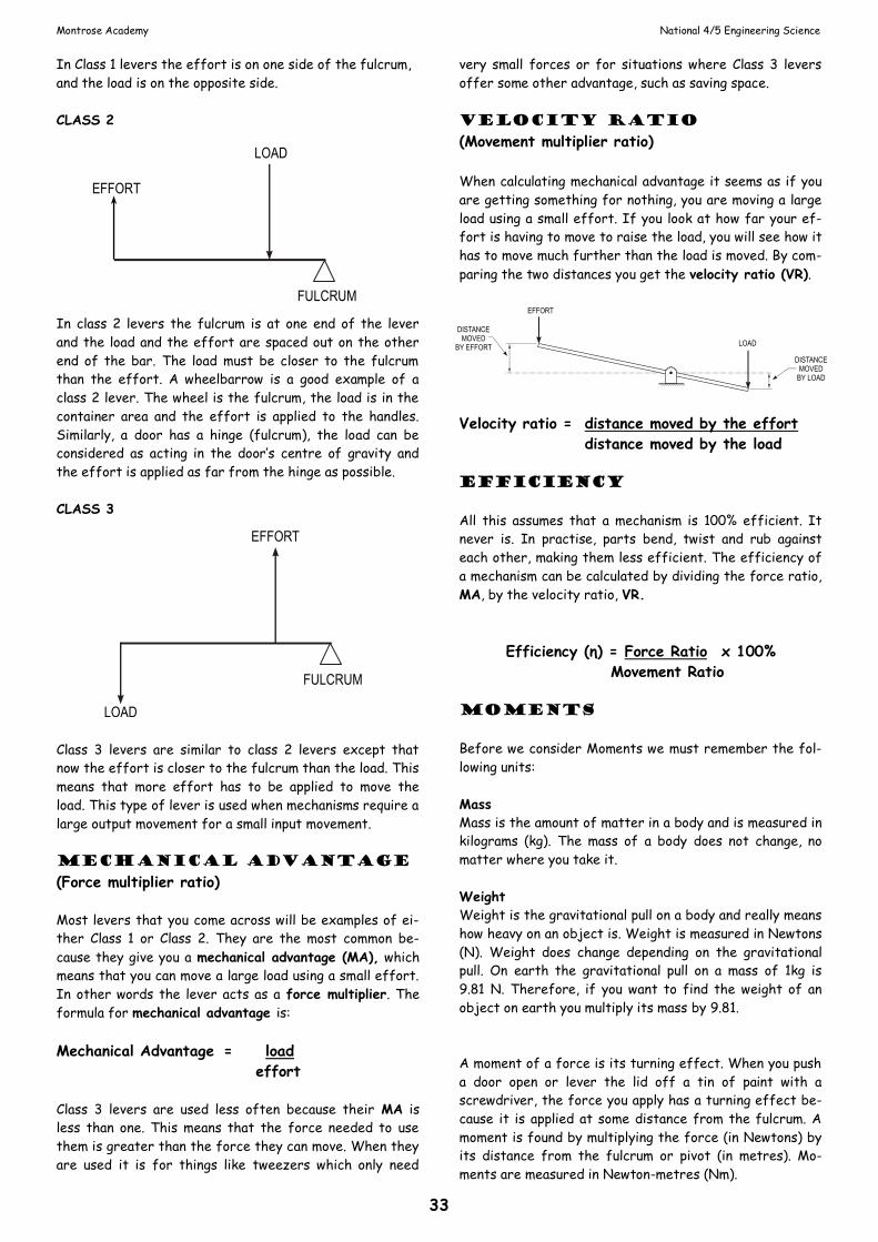
velocity ratio
(Movement multiplier ratio)
When calculating mechanical advantage it seems as if you
are getting something for nothing, you are moving a large
load using a small effort. If you look at how far your ef-
fort is having to move to raise the load, you will see how it
has to move much further than the load is moved. By com-
paring the two distances you get the velocity ratio (VR).
Velocity ratio = distance moved by the effort
distance moved by the load
efficiency
All this assumes that a mechanism is 100% efficient. It
never is. In practise, parts bend, twist and rub against
each other, making them less efficient. The efficiency of
a mechanism can be calculated by dividing the force ratio,
MA, by the velocity ratio, VR.
Efficiency (η) = Force Ratio x 100%
Movement Ratio
moments
Before we consider Moments we must remember the fol-
lowing units:
Mass
Mass is the amount of matter in a body and is measured in
kilograms (kg). The mass of a body does not change, no
matter where you take it.
Weight
Weight is the gravitational pull on a body and really means
how heavy on an object is. Weight is measured in Newtons
(N). Weight does change depending on the gravitational
pull. On earth the gravitational pull on a mass of 1kg is
9.81 N. Therefore, if you want to find the weight of an
object on earth you multiply its mass by 9.81.
A moment of a force is its turning effect. When you push
a door open or lever the lid off a tin of paint with a
screwdriver, the force you apply has a turning effect be-
cause it is applied at some distance from the fulcrum. A
moment is found by multiplying the force (in Newtons) by
its distance from the fulcrum or pivot (in metres). Mo-
ments are measured in Newton-metres (Nm).
EFFORT
LOAD
DISTANCEMOVED
BY LOAD
DISTANCEMOVED
BY EFFORT
EFFORT
LOAD
FULCRUM
EFFORT
LOAD
FULCRUM

Montrose Academy National 4/5 Engineering Science
34
the principle of
moments
The principle of moments states that if a body is in equi-
librium (is perfectly balanced), then the total sum of the
clockwise moments is equal to the total sum of the anti-
clockwise moments. Moments may be taken about any
point on the body, usually a pivot point. The Greek letter
∑ stands for ‘the sum of’ and can be used as a shorthand
way of writing the principle of moments:
∑CWM = ∑ACWM
F1 x d1 = F2 x d2
Example
Answer For equilibrium, the ∑CWM = ∑ACWM. A moment is a
force multiplied by a distance
∑CWM = ∑ACWM
F1 x d1 = F2 x d2
The load is exerting a clockwise moment; that is, it is
tending to make the lever turn clockwise.
Clockwise moment = 200 N ´ 2 m = 400 Nm
The effort is exerting an anticlockwise moment.
Anticlockwise moment = 400 N x 1 m = 400 Nm
Therefore the lever is in a state of equilibrium.
linkages
Levers are often linked together to transmit force or
motion. A linkage consists of two or more levers connect-
ed together. Linkages are useful for changing the direc-
tion of an input or for giving greater force or distance
amplifications.
Five common linkages found in many machines are shown
below.
In example above the output motion is reversed and the
fulcrum is the same distance from the input and output
and therefore the same force.
The figure above is similar to the first except the ful-
crum is closer to the output and therefore the output
force is multiplied.
This figure allows the input and output motion to be the
same, but because the fulcrum is further away from the
input the output force is multiplied.
This combination transforms reciprocating motion into
rotary motion.
Lastly, these lazy tongs allow for extra reach.
Montrose Academy National 4/5 Engineering Science
35
Free-body diagrams
It is important to isolate different parts of a structure
or body from its adjacent surroundings. In a line diagram
this can be done by drawing a free-body diagram, which is
a diagrammatic representation of all or part of the struc-
ture showing the forces affecting it.
Example
Figure 1
If all the visual components acting on the structure or
body were removed and replaced with their force value, a
simplified diagram would allow a better understanding of
how the forces are affecting the structure.
Figure 1: free-body diagram
Figure 1 is a simplified free-body diagram of figure 1. The
forces representing the bus and the weight of the bridge
act downwards and are taken through the centre of the
bus and the middle of the bridge. Because of the point of
contact of the bus, the arrow is drawn through its centre.
The forces Fh and Fv represent the forces that the sup-
ports have on the structure, therefore they also have to
be shown. We could be more detailed and draw the angled
support for the bridge in the rock face.
beams
Apart from levers, structural beams and beam-related
objects are also affected by forces and turning moments.
For a horizontal structure to be stable (in equilibrium)
when being affected by forces in a vertical plane, the
following conditions must be satisfied.
The sum of the forces acting upwards must equal the sum
of the forces acting downwards.
∑ upwards forces = ∑ downwards forces
The sum of the clockwise moments about any point must
equal the sum of the anticlockwise moments about the
same point. That is:
∑ clockwise moments = ∑ anticlockwise moments
(principle of moments)
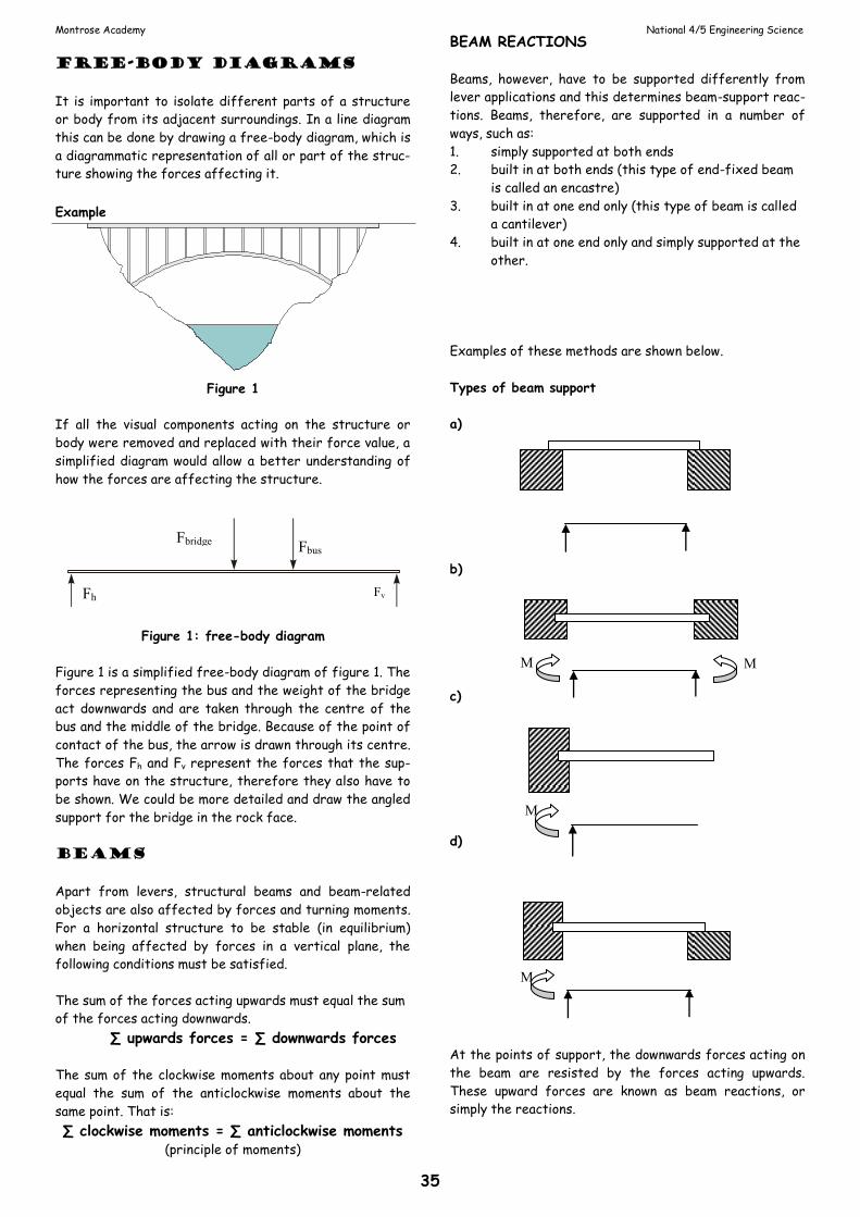
BEAM REACTIONS
Beams, however, have to be supported differently from
lever applications and this determines beam-support reac-
tions. Beams, therefore, are supported in a number of
ways, such as:
1. simply supported at both ends
2. built in at both ends (this type of end-fixed beam
is called an encastre)
3. built in at one end only (this type of beam is called
a cantilever)
4. built in at one end only and simply supported at the
other.
Examples of these methods are shown below.
Types of beam support
a)
b)
c)
d)
At the points of support, the downwards forces acting on
the beam are resisted by the forces acting upwards.
These upward forces are known as beam reactions, or
simply the reactions.
Fv
Fbus Fbridge
Fh
M M
M
M

Montrose Academy National 4/5 Engineering Science
36
Gears
Gears are toothed wheels designed to transmit rotary
motion and power from one part of a mechanism to anoth-
er. They are fitted to shafts with special devices called
keys (or splines, etc.) that ensure that the gear and the
shaft rotate together. Gears are used to increase or de-
crease the output speed of a mechanism and can also be
used to change the direction of motion of the output.
The type of gear wheel most commonly used is the spur
gear.
SIMPLE GEAR TRAIN
Gears work by interlocking or ‘meshing’ the teeth of the
gears together as shown in figure 2.
Figure 2
When two or more gears are meshed they form a ‘gear
train’. The input gear, which causes the system to move, is
called the ‘driver’; the output gear is called the ‘driven’.
Both gears are mounted and supported on separate
shafts.
MOVEMENT-MULTIPLIER RA-
TIO IN GEARS
The ratio of change in speed between the gears is called
the movement-multiplier ratio.
The ratio of a gear system is found by dividing the num-
ber of teeth on the driven gear by the number of teeth
on the driver gear. This can be used to calculate the out-
put speed of a gear system.
Movement ratio = number of teeth on driven gear
number of teeth on driver gear
Example For the gear system shown in figure 2 the gear multiplier
ratio is
This means that if gear A was rotating at 100 rpm
(revolutions per minute) clockwise then gear B would ro-
tate at 200 rpm anticlockwise.
Gears can also be used to decrease the speed of a mecha-
nism, as shown in figure 3.
Figure 3
If gear A is still rotating at 100 rpm in a clockwise direc-
tion then gear B will now rotate at 50 rpm in an anticlock-
wise direction.
It is sometimes necessary to obtain a change in speed
without changing the direction of the driven gear.
Idler gears
To get the driven gear to rotate in the same direction as
the driver, a third gear is inserted in the system. This
idler gear has no effect on the multiplier ratio of the sys-
tem. The size of the idler is not important and is normally
a small gear, as in figure 4.
Figure 4
The multiplier ratio for the simple gear train in figure 4 is
still 2:1. If gear A still rotates at 100 rpm clockwise then
the output of gear B will rotate at 50 rpm clockwise. ng
the direction of the driven gear. How can this be done?
Ratchet and pawl
A wheel with saw-shaped teeth round its rim is called a
ratchet. The ratchet wheel usually engages with a tooth-
shaped lever called a pawl. The purpose of the pawl is to
allow rotation in one direction only and prevent rotation in
the opposite direction.
1:2or2
1
24
12RatioGear

Montrose Academy National 4/5 Engineering Science
37
Compound gears
If gears are required to produce a very large change in
speed, for example if the multiplier ratio is 100:1, then
problems can arise with the size of gear wheels if a simple
gear train is used. This problem can be overcome by
mounting pairs of gears on the same shaft, as shown in
figure 5.
This arrangement is described as a compound gear train.
This type of gear train can also be used to provide differ-
ent outputs moving at different speeds and in different
directions.
Figure 5
The compound gear system in figure 6 shows how the
shafts are connected between the ‘pairs’ of gears. Gears
B and C are connected and rotate at the same speed. To
calculate the multiplier ratio for the gear train it is nec-
essary to calculate the ratio for each pair of meshing
gears.
Figure 6
Example The multiplier ratio for the system shown in figure 8 is
as follows.
The multiplier ratio for the first pair of meshing teeth is
The multiplier ratio for the second pair of meshing teeth
is
The total multiplier ratio is calculated by multiplying both
ratios:
For an input speed of 100 rpm, the output speed would be
less than 5 rpm, that is, 4.17 rpm.
Worm and wheel
Another way of making large speed reductions is to use a
worm gear and wormwheel, as shown in figure 7. The
worm, which looks rather like a screw thread, is fixed to
the driver shaft. It meshes with a wormwheel, which is
fixed to the driven shaft. The driven shaft runs at 90
degrees to the driver shaft. When considering the speed
changes in most worm gear systems, you can think of the
worm as if it were a spur gear with one tooth. It is a sin-
gle tooth wrapped around a cylinder.
Figure 7
Bevel gears
Bevel gears, like worm gears, use shafts at 90 degrees to
each other, as shown in figure 8.
Figure 8
Torque and Drive Systems
Torque is the amount of turning produced by a force. The
turning or twisting action exerted by a force or number
of forces will cause or tend to cause rotary motion. Drive
shafts in cars, tools turning, belt-and-pulley systems, etc.
are all affected by torque.
A simple example of this is when the propeller of a model
builder’s toy boat connected to a rubber band is twisted
by torsion forces. When the propeller is released, the
rubber band, having been under the twisting effect, re-
leases energy to drive the boat through the water.
Example 1 How much torque is required to tighten the nut if the
force required is 45 N and the radius of the tool is 200
mm.
Torque = force x radius
= 45 N x 200 mm
work done by torque = 9Nm
1:420
80
driver
drivenAB of Ratio
1:610
60CD of Ratio
driver
driven
1:241
6
1
4ratioTotal

Montrose Academy National 4/5 Engineering Science
38
Belt-and-chain drives
Many mechanisms make use of rotary motion, often pro-
vided by someone turning a handle or by an electric motor.
But to be useful, this rotary motion has to be frequently
transmitted from one part of a mechanism to another,
often with a change of speed. While gears can be connect-
ed together in a simple gear train, if too many gears are
used there can be large efficiency losses due to friction.
There are two simple means of transmitting rotary motion
over relatively large distances. One is to use a belt
wrapped around two or more pulleys as shown in figure 9.
The belt is tightened or tensioned by pulling one of the
pulleys out and locking it in place. Pulleys are thin metal
discs with a groove cut into the circumference of the
disc.
Figure 9: belt-and-
pulley symbol
The belt is angled as
shown in figure 10 to give better grip to prevent the belt
from slipping. A change in speed can be accomplished by
varying the diameter of the driver pulley and driven pul-
ley.
Figure 10: vee belt for extra grip
Changes in direction can be achieved by crossing the belt
as shown in the figure below. In belt-drive systems, the
belt must be crossed between the two pulleys if the di-
rection of the output shaft is to be opposite to that of
the input shaft.
Belt drives are used in a wide variety of situations. They
are made from a composite of two materials, rubber and
string. The string helps to prevent the rubber from
stretching too much. Drive belts are inexpensive to pro-
duce. They are easy to replace and need little mainte-
nance, as they do not require lubrication. They also absorb
shock loads. For instance, if a belt drive is used to trans-
mit the power from a motorcycle engine to the rear wheel
and the biker tries to ‘wheelie’, the belt tends to slip, pre-
venting damage to the engine.
MULTIPLIER RATIO FOR BELT DRIVES
Pulley systems can be used to transmit rotary motion over
a large distance. The input rotary motion is often from a
fixed-speed and fixed-torque electric motor. Torque is a
turning force produced by mechanisms and is measured in
Newton-metres (Nm). Changing the ratio of the diameters
of the pulleys can vary both the speed of the output and
the torque at the output.
Figure 11: belt-and-pulley system
TOOTHED BELTS
Belt drives tend to use their ability to slip to their ad-
vantage. However, where slippage would damage a mecha-
nism, toothed belts have been developed that retain the
advantages of normal belts but do not slip.
CHAIN DRIVES
Where large forces have to be transmitted, and there can
be no slippage allowed, chain drives are used. Instead of a
pulley, a toothed wheel known as a sprocket is used to
drive a chain. The chain in turn drives another toothed
wheel. Once again, the speed can be varied by making the
sprockets different sizes.
Figure 12: Bicycle-chain drive
40 mm
120 mm
DRIVEPULLEY
MOTOR
DRIVEN
DRIVER
Montrose Academy National 4/5 Engineering Science
39
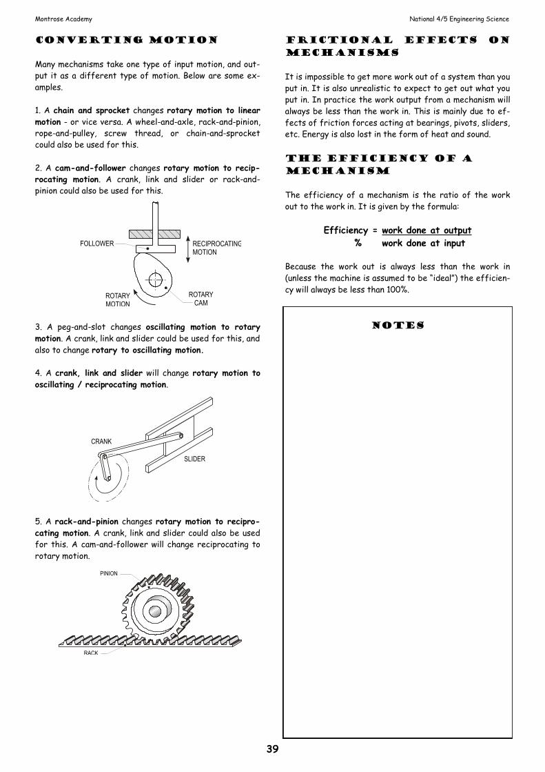
converting motion
Many mechanisms take one type of input motion, and out-
put it as a different type of motion. Below are some ex-
amples.
1. A chain and sprocket changes rotary motion to linear
motion - or vice versa. A wheel-and-axle, rack-and-pinion,
rope-and-pulley, screw thread, or chain-and-sprocket
could also be used for this.
2. A cam-and-follower changes rotary motion to recip-
rocating motion. A crank, link and slider or rack-and-
pinion could also be used for this.
3. A peg-and-slot changes oscillating motion to rotary
motion. A crank, link and slider could be used for this, and
also to change rotary to oscillating motion.
4. A crank, link and slider will change rotary motion to
oscillating / reciprocating motion.
5. A rack-and-pinion changes rotary motion to recipro-
cating motion. A crank, link and slider could also be used
for this. A cam-and-follower will change reciprocating to
rotary motion.
frictional effects on
mechanisms
It is impossible to get more work out of a system than you
put in. It is also unrealistic to expect to get out what you
put in. In practice the work output from a mechanism will
always be less than the work in. This is mainly due to ef-
fects of friction forces acting at bearings, pivots, sliders,
etc. Energy is also lost in the form of heat and sound.
the efficiency of a
mechanism
The efficiency of a mechanism is the ratio of the work
out to the work in. It is given by the formula:
Efficiency = work done at output
% work done at input
Because the work out is always less than the work in
(unless the machine is assumed to be “ideal”) the efficien-
cy will always be less than 100%.
notes
CRANK
SLIDER
PINION
RACK
ROTARYCAM
ROTARYMOTION
FOLLOWER RECIPROCATINGMOTION