morphology, control and passive dynamics - … · morphology = the structure and mechanical...
TRANSCRIPT

Morphology, control and Morphology, control and passive dynamicspassive dynamics
Poramate Manoonpong

Morphology = the structure and mechanical characteristics of theMorphology = the structure and mechanical characteristics of the robot bodyrobot body
Not only Kinematics and Dynamics of robots but also the control Not only Kinematics and Dynamics of robots but also the control required for robot behaviorsrequired for robot behaviors
Well designed morphology Poor designed morphologyreduction in control &improved controllability low controllability
require complex control algorithm inadequate for the task
• Passive dynamics (Collins S. [1], etc.)
• Extending idea from Passive dynamics to running robots (Tao G. [3], Kimura H. [4], etc.)
• Climbing robots (Metin S. [5], etc.)
• Underwater robot (Edward C. [6])

Morphology and Control
Behavior genration(agent-environment interaction)
Embodied AI [R.A. Brooks, 1980s]
[Gray Walter‘s Turtles, 1953]

Special Issue on Morphology, Control and Passive Dynamics:(Robotics and Autonomous systems (Vol. 54))
The collection of papers:
1.1. The conceptual advances in understanding the interaction between morphology, control and behavior.
2.2. A novel technique for enhancing controllability using morphology design.
3.3. Analytical methods and computational tools for investigating the effect of morphological characteristics on dynamics and behavior.
4.4. New control methods for better exploiting the dynamics of a given morphology for control.

1.1. Sensing through body dynamicsSensing through body dynamics (F. Iida, R. Pfeifer)(F. Iida, R. Pfeifer)
Goal: Goal: Exploring design principles of the whole body dynamics for the purpose of sensing
4-legged robot: spring-mass model with four active joints, rubber surface at the ground contact in each leg (for higher fiction in walking forwards)
Motor control: Central Pattern Generator CPG and no feedback
Experiments:
1. Testing on a real machine to obtain data
2. Using simulation and compare to the real one

Experiment 1 (Real machine): The stability of the locomotion method without sensor feedback (periodic gait pattern)
Gait 0 (Hopping higher)Gait 1 (Larger forward velocity)

Experiment 2 : Simulation model in Mathworks MathLab 7.01 with SimMechnics toolbox
- 5 body segments- Linear springs - Two motors at hip and shoulder joints- Angular sensors- Ground friction model
Experiment 3: Using the simulation to characterize the relation between Locomotion, Behavior and Sensory information
Stable
Stable
Unstable
(a) W = 4.7 Hz, Phase = 0.3
Friction = 0.9 (static), 0.8 (dynamic)
(b) W = 4.7 Hz, Phase = 0.3
Friction = 0.7 (static), 0.6 (dynamic)
(c) W = 4.9 Hz, Phase = 0.4
Friction = 0.7 (static), 0.6 (dynamic)
(a) (b) (c)
(a)
(b)
(c)
Pressure sensor
Joint angle
Acc sensor
Motor torque
Monitoring friction
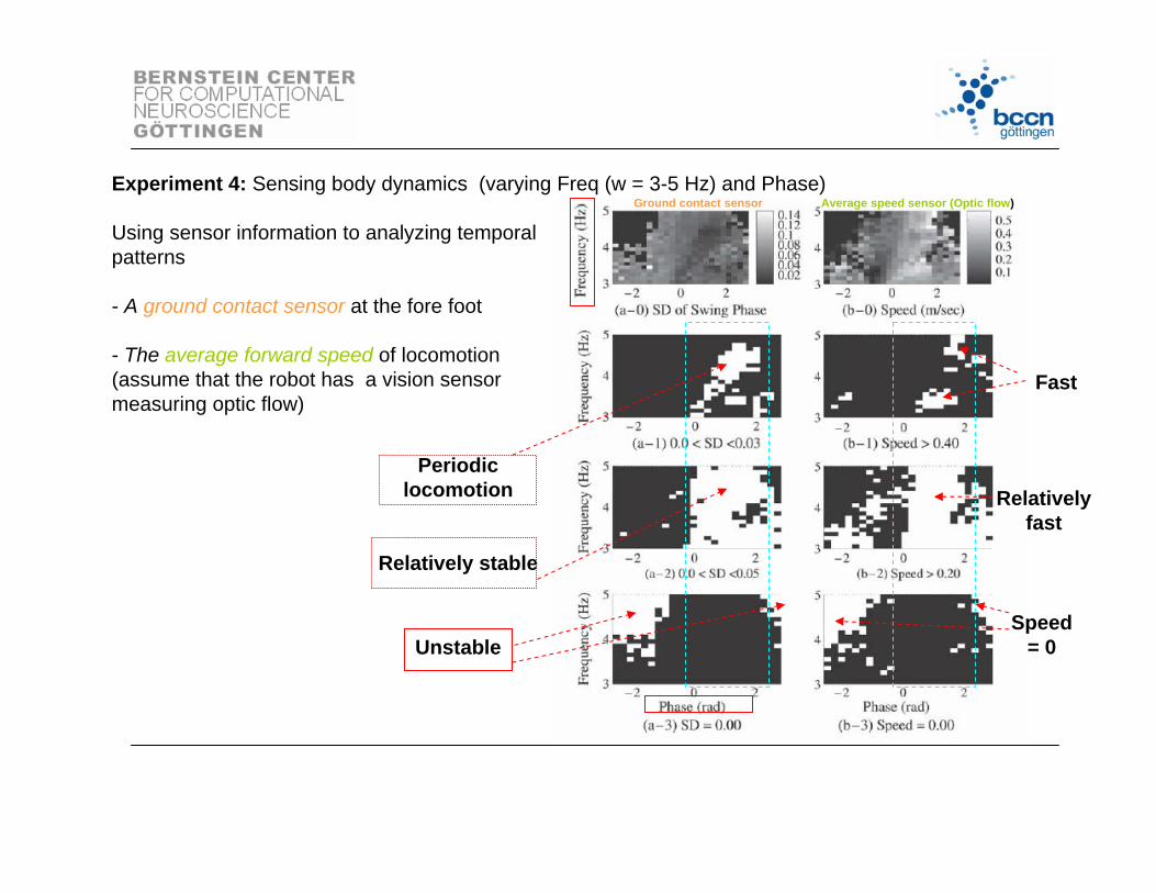
Experiment 4: Sensing body dynamics (varying Freq (w = 3-5 Hz) and Phase)
Using sensor information to analyzing temporal patterns
- A ground contact sensor at the fore foot
- The average forward speed of locomotion (assume that the robot has a vision sensor measuring optic flow)
Periodic locomotion
Relatively stable
Unstable
Ground contact sensor Average speed sensor (Optic flow)
Fast
Relatively fast
Speed = 0

Experiment 5: Sensing physical properties
5.1 Varying body mass (0.5, 1.0, 1.5 Kg.):
- Ground contact sensor (GS)- Speed detector sensor (vision (VS)
Ground contact sensor
Average speed sensor (Optic flow)
0.5 kg
1.0 kg
1.5 kg
The difference of the body mass can be identified by GS and VS
0.5 kg
1.0 kg
1.5 kg

Experiment 5: Sensing physical properties
5.2 Ground friction (0.5, 0.65, 0.8):
- Mass = 0.5 kg- Ground contact sensor (GS)- Speed detector sensor (vision (VS)
Ground contact sensor
Average speed sensor (Optic flow)
0.5
0.65
0.8
The difference of the ground friction can be identified
by GS and VS
0.5
0.65
0.8
Conclusion
- Applying the sensory information from different channels, e.g. pressure sensor on the foot, locomotion speed, force sensor on the leg joints, etc., to let the robot understand its situation or environment condition
- They can be used to determine the stable behavior patterns
-The body dynamics can be exploited for sensing
- The physical properties (body weight, friction) are reflected to the sensory information

3. On the influence of morphology of tactile sensors for behavio3. On the influence of morphology of tactile sensors for behavior r and control and control (M. Fend, S. Bovet, R. Pfeifer)(M. Fend, S. Bovet, R. Pfeifer)
Goal: Goal: - Investigating the relation between the morphology of the sensor distribution on the robot body different tasks (obstacle avoidance and wall following)
- Reducing the amount of processing in the brain of the agent by using the appropriate morphology of the sensors
Mobile robot with the whisker arrays
Motor control: Reactive control

Experiments:
1. Testing 3 different morphologies of the sensor mounted on the robot for obstacle avoidance task (reactive controller).
2. Using learning algorithm to the controller and then using evolutionary algorithm to optimize the controller and the morphology of the whiskers for obstacle avoidance task.
3. Evaluating the same morphologies as (1) and (2) on a different task “ wall following”
Like animals

Experiment 1: The performance of the robot system is evaluated by how evenly the experimental space is covered and how much the robot wiggles (how often the robot changes direction)
OK

Experiment 2: Learning of obstacle avoidance on the robot
OKDistributed adaptive control: IR sensors used as the pre-wired reflex; Wij = 0 +
Learning time is limited to 2 mins

Results

Experiment 3: Using Co-evolution to optimize the controller, the morphology of the whiskers and the influence of different whisker properties (rigid and flexible)
Almost like Morphology A

Experiment 4: Wall-following with the reactive controller
smooth
Conclusion
- Morphology A = suitable for obstacle avoidance
- Morphology C = suitable for wall following , similar to animals, e.g. rat
- Rat uses its whisker mostly for wall following while it uses also another sensor system, e.g. vision, for obstacle avoidance task
-The performance of the system can be enhanced with an appropriate morphology

Example:

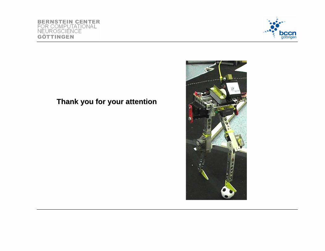
Thank you for your attentionThank you for your attention