morse modulari di precisione o r k hold in...
TRANSCRIPT
3
www.gerardi.it catalogo serraggio 2014
MORSE MODULARI DI PRECISIONEPRECISION MODULAR VISES
MORSE MODULARI DI PRECISIONEPRECISION MODULAR VISES
3CAPITOLO CHAPTER
G
ERARD
I W
ORKHOLDING
G
ERARD
I W
ORKHOLDING
STD e StandardFLEXELEMENTI MODULARI - MODULAR ELEMENTS
3.2 STD www.gerardi.it workholding catalogue 2014
Le morse Gerardi sono ormai considerate sinonimo di produzione ad alto livello tecnologico per l’accurata scelta dei materiali impiegati e per la precisione raggiunta anche nei minimi particolari. Accuratamente rettificate in ogni loro particolare ed ampiamente collaudate, consentono: una capacità di massimo rendimento della macchina, un forte carico di pressione, una maggior potenza di taglio, esclusione totale di vibrazioni, minor usura dell’utensile una più precisa lavorazione. La costruzione con un sistema di elementi componibili consente le più svariate possibilità di impiego e combinazioni in caso di necessità.
Gerardi vises are manufactured under rigid quality control. Only the most suitable materials are used, and the accuracy of even the smallest components is assured. As a result of the high standard construction Gerardi vises can maintain their accuracy under the most severe operating conditions.Hardened and Ground steel construction throughout allowing you maximum machine performance with: bigger clamping power, bigger cutting performances, total exclusion of vibrations, lower tool wear; higher precision during machinework. The modular design and the concept of interchangeability makes possible a wide variety of set up combination and solutions.
Gerardi modular elements allow You perfect clamping even of big workpieces which need the heaviest machining using the machine table as surface. Modular elements are the best example of the extreme versatility of the Gerardi Modular System. The avalaibility of the broadest assortment program allows to build with standard solutions even the fixtures You thought special. They are a solution for a lot of applications and, with the many reference points available, a perfect complement or alternative to single or double vises
Gli elementi modulari Gerardi Vi permettono di ottimizzare i bloccaggi di pezzi particolarmente grandi, che richiedano le lavorazioni più gravose, sfruttando anche il piano della tavola della macchina come punto di appoggio. Gli elementi modulari sono sicuramente l’esempio (vedere applicazioni alle pag. seg.) più lampante dell’estrema versatilità del Sistema Modulare Gerardi. La disponibilità di una vastissima gamma di composizioni (modulari) permette di realizzare con soluzioni standard anche gli allestimenti che credevate speciali.
ELEMENTI MODULARIMODULAR ELEMENTSPagg. 3.2 - 3.14
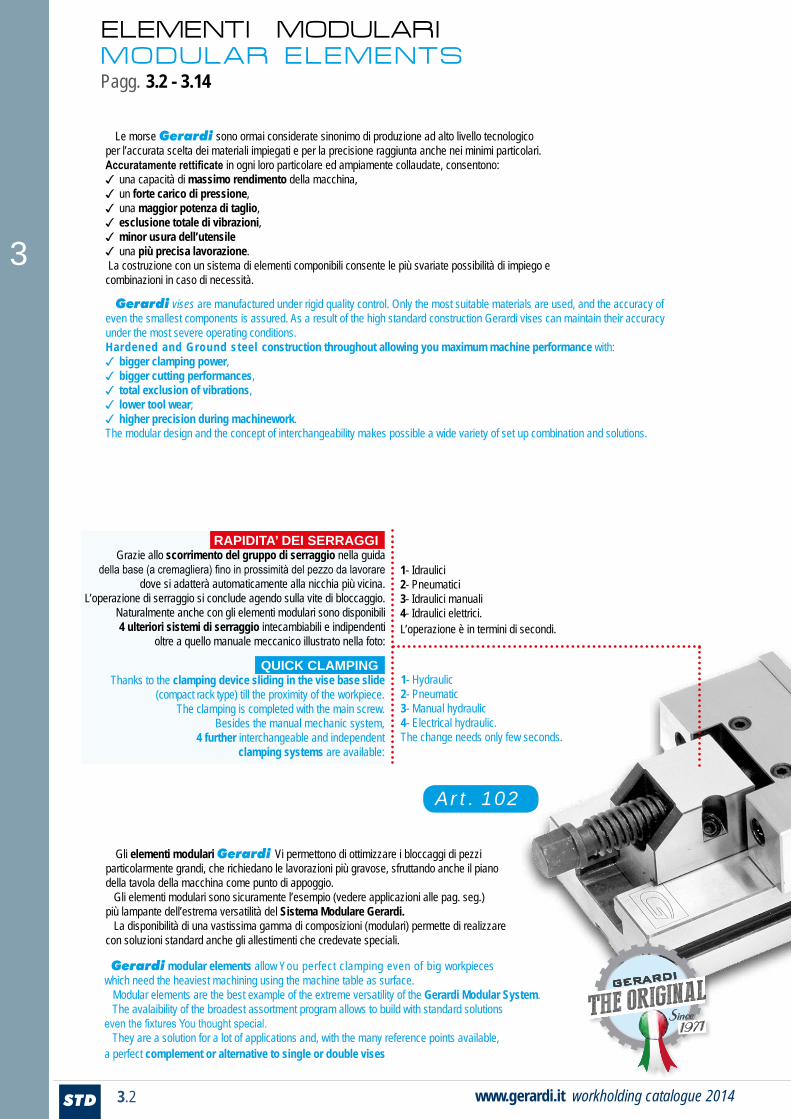
1- Idraulici 2- Pneumatici 3- Idraulici manuali 4- Idraulici elettrici. L’operazione è in termini di secondi.
Grazie allo scorrimento del gruppo di serraggio nella guida della base (a cremagliera) fino in prossimità del pezzo da lavorare
dove si adatterà automaticamente alla nicchia più vicina. L’operazione di serraggio si conclude agendo sulla vite di bloccaggio.
Naturalmente anche con gli elementi modulari sono disponibili 4 ulteriori sistemi di serraggio intecambiabili e indipendenti
oltre a quello manuale meccanico illustrato nella foto:
Thanks to the clamping device sliding in the vise base slide (compact rack type) till the proximity of the workpiece.
The clamping is completed with the main screw. Besides the manual mechanic system,
4 further interchangeable and independent clamping systems are available:
RAPIDITA’ DEI SERRAGGI
QUICK CLAMPING
seconds.
1- Hydraulic 2- Pneumatic 3- Manual hydraulic 4- Electrical hydraulic.The change needs only few seconds.
Art. 102
GERARDI GERARDI GERARDI
Since 1971
3
3.3 STDwww.gerardi.it catalogo serraggio 2014
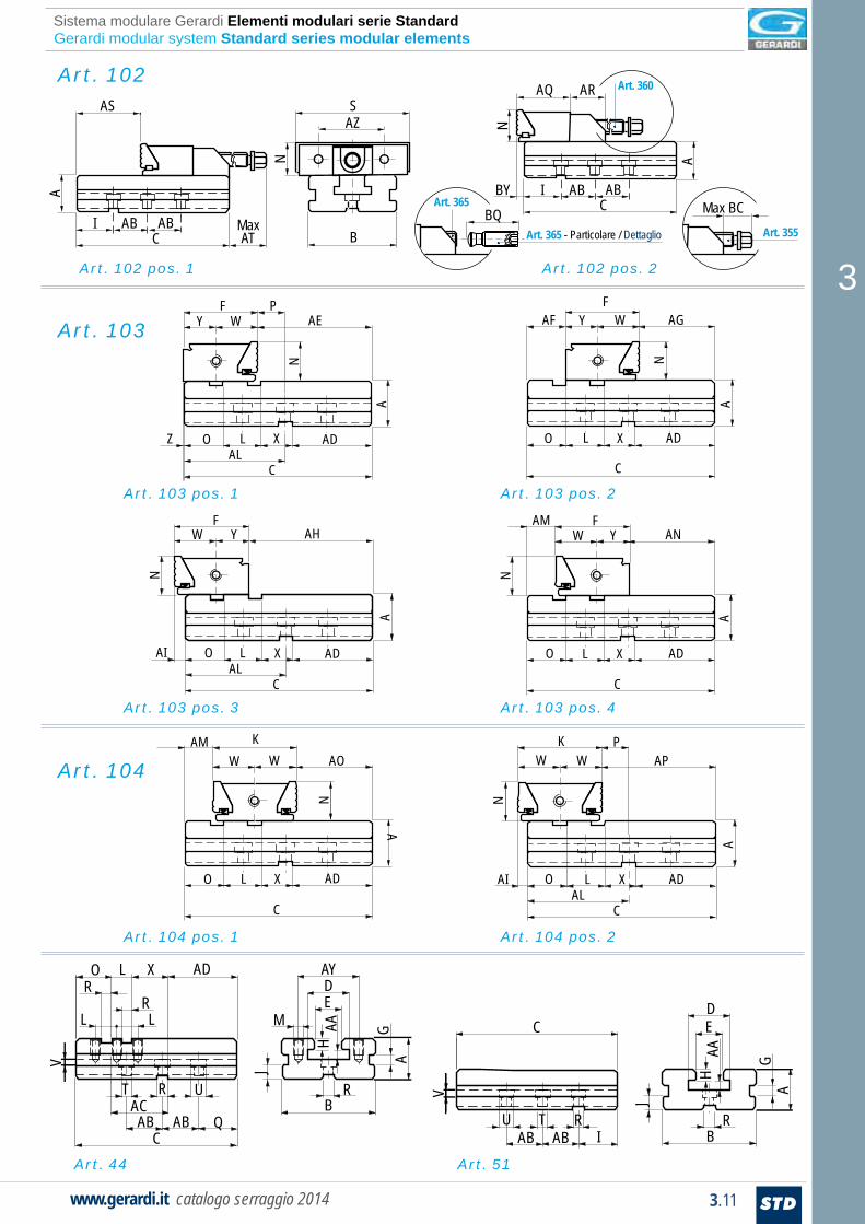
Vise bases (for Art. 102 and 104) or base extensions (for Art. 102) are always built with longitudinal and cross keyways in order to be aligned with the machine axis. Furthermore fixed jaws have always 2 different positions in order to be able to clamp even workpieces positioned on the machine table directly (see images on pages 3.4, 3.5).
Slittone base (per Art. 103 e 104) o elemento di prolunga (per Art. 102) sempre previsti con chiavette di posizionamento longitudinali e trasversali per allineamento agli assi della macchina. Inoltre per le ganasce fisse sono sempre previsti 2 differenti posizionamenti per permettere alle stesse anche la possibilità di serrare pezzi direttamente appoggiati sul piano / tavola della macchina (vedi immagini a pag. 3.4, 3.5).
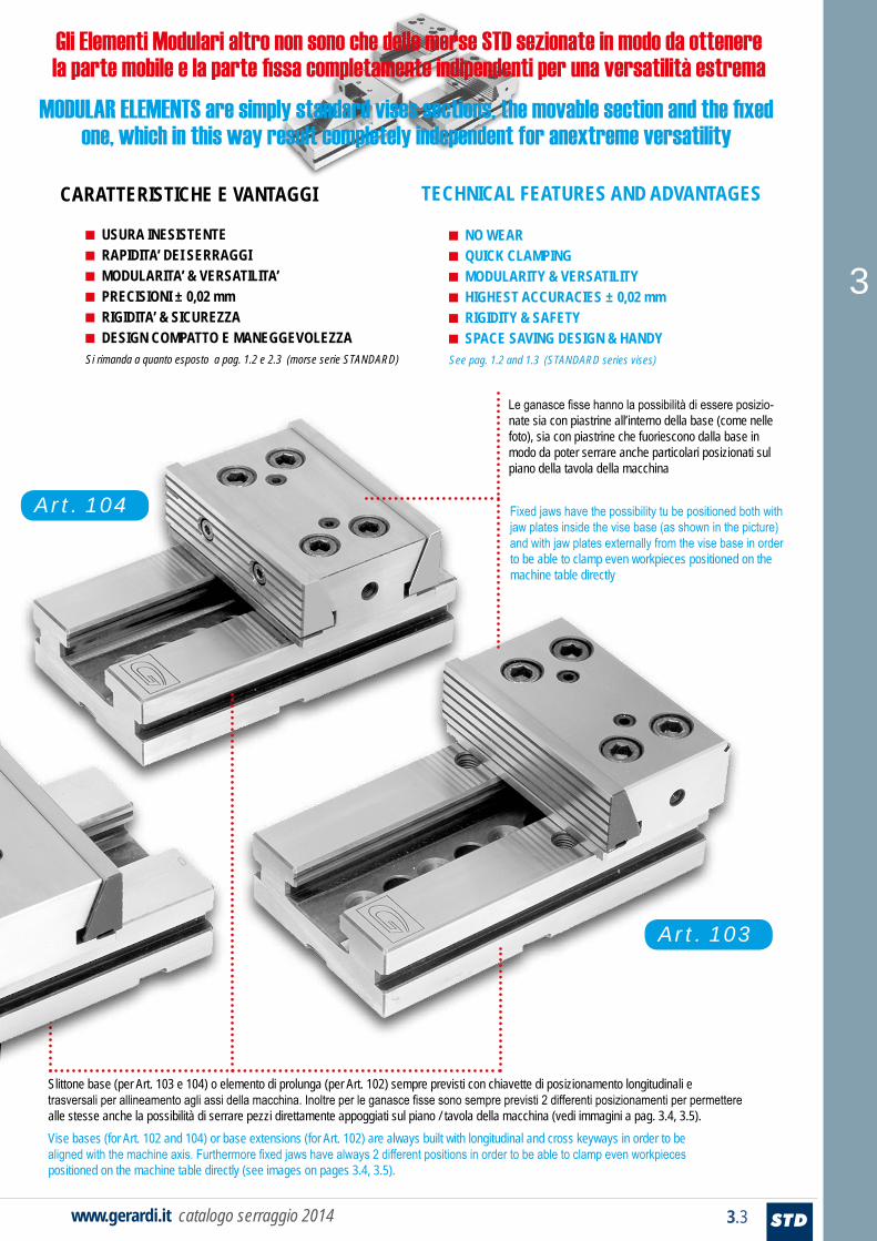
Fixed jaws have the possibility tu be positioned both with jaw plates inside the vise base (as shown in the picture) and with jaw plates externally from the vise base in order to be able to clamp even workpieces positioned on the machine table directly
Le ganasce fisse hanno la possibilità di essere posizio-nate sia con piastrine all’interno della base (come nelle foto), sia con piastrine che fuoriescono dalla base in modo da poter serrare anche particolari posizionati sul piano della tavola della macchina
Gli Elementi Modulari altro non sono che delle morse STD sezionate in modo da ottenere la parte mobile e la parte fissa completamente indipendenti per una versatilità estrema
MODULAR ELEMENTS are simply standard vises sections, the movable section and the fixedone, which in this way result completely independent for anextreme versatility
Art. 104
Art. 103
TECHNICAL FEATURES AND ADVANTAGESCARATTERISTICHE E VANTAGGI
■ USURA INESISTENTE■ RAPIDITA’ DEI SERRAGGI■ MODULARITA’ & VERSATILITA’■ PRECISIONI ± 0,02 mm■ RIGIDITA’ & SICUREZZA■ DESIGN COMPATTO E MANEGGEVOLEZZASi rimanda a quanto esposto a pag. 1.2 e 2.3 (morse serie STANDARD)
■ NO WEAR■ QUICK CLAMPING■ MODULARITY & VERSATILITY■ HIGHEST ACCURACIES ± 0,02 mm■ RIGIDITY & SAFETY■ SPACE SAVING DESIGN & HANDYSee pag. 1.2 and 1.3 (STANDARD series vises)
3
3
3.4 STD www.gerardi.it workholding catalogue 2014
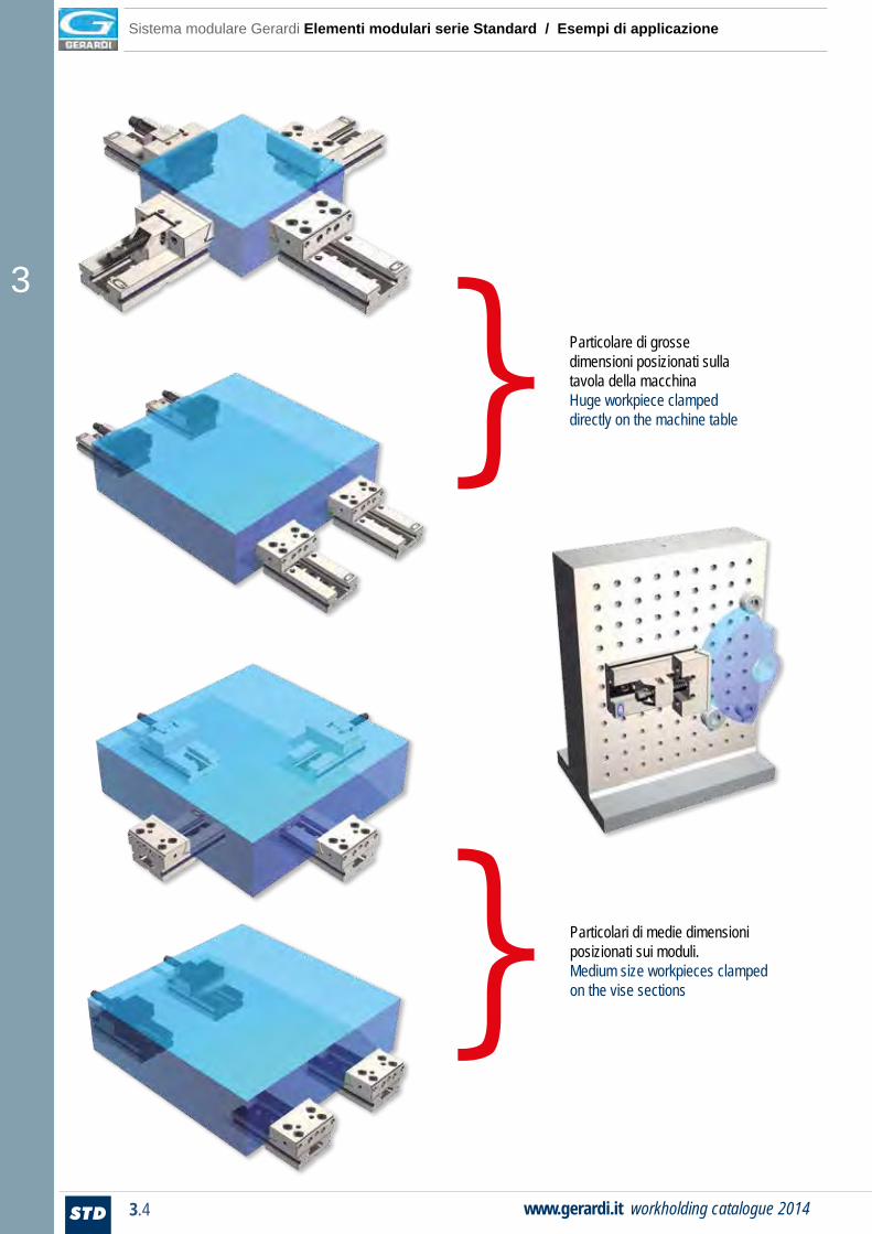
Sistema modulare Gerardi Elementi modulari serie Standard / Esempi di applicazione
Particolare di grosse dimensioni posizionati sulla tavola della macchinaHuge workpiece clampeddirectly on the machine table
Particolari di medie dimensioni posizionati sui moduli. Medium size workpieces clamped on the vise sections
}
}

3
3.5 STDwww.gerardi.it catalogo serraggio 2014
Art. 1 + Art. 51Per realizzare una stazione mobile è sufficiente sfilare dalla morsa Art. 1 il gruppo di bloccaggio Art. 258 + la ganascia mobile Art. 127 ed inserirli in un elemento di prolunga Art. 51.In order to get a movable vise section it is enough to remove from vise Art. 1 the blocking device Art. 258 + the movable jawArt. 127 and to assemble them on an extension base Art. 51
Elemento modulare fisso doppio (Art. 104) + 2 elementi modulari mobili (Art. 102)Double fixed vise section (Art. 104) + 2 movable vises sections (Art. 102)
Art. 102
Art. 102
Art. 104
Art. 258
Art. 127
Art. 51
Art. 258
Art. 127
Art. 51
Gerardi modular system Standard series modular elements / Typical arrangements
Elementi modulari montati su cubo a croce Art. 5Modular elements assembled on cross cube type Art. 57
}
}}
3
3.6 STD www.gerardi.it workholding catalogue 2014
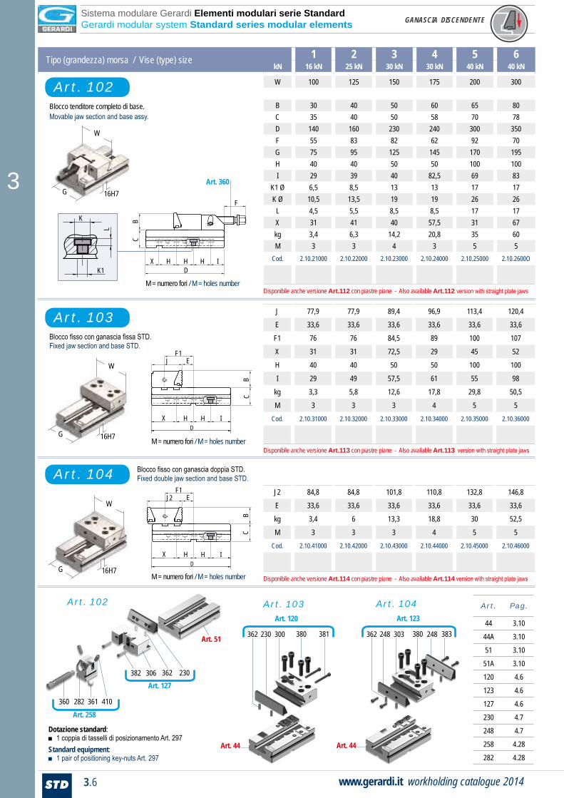
Tipo (grandezza) morsa / Vise (type) size 1 2 3 4 5 6kN 16 kN 25 kN 30 kN 30 kN 40 kN 40 kN
W 100 125 150 175 200 300
B 30 40 50 60 65 80C 35 40 50 58 70 78D 140 160 230 240 300 350F 55 83 82 62 92 70G 75 95 125 145 170 195H 40 40 50 50 100 100I 29 39 40 82,5 69 83
K1 Ø 6,5 8,5 13 13 17 17K Ø 10,5 13,5 19 19 26 26
L 4,5 5,5 8,5 8,5 17 17X 31 41 40 57,5 31 67kg 3,4 6,3 14,2 20,8 35 60M 3 3 4 3 5 5
Cod. 2.10.21000 2.10.22000 2.10.23000 2.10.24000 2.10.25000 2.10.2600O
J 77,9 77,9 89,4 96,9 113,4 120,4
E 33,6 33,6 33,6 33,6 33,6 33,6
F1 76 76 84,5 89 100 107
X 31 31 72,5 29 45 52
H 40 40 50 50 100 100
I 29 49 57,5 61 55 98
kg 3,3 5,8 12,6 17,8 29,8 50,5
M 3 3 3 4 5 5Cod. 2.10.31000 2.10.32000 2.10.33000 2.10.34000 2.10.35000 2.10.36000
J2 84,8 84,8 101,8 110,8 132,8 146,8
E 33,6 33,6 33,6 33,6 33,6 33,6
kg 3,4 6 13,3 18,8 30 52,5
M 3 3 3 4 5 5Cod. 2.10.41000 2.10.42000 2.10.43000 2.10.44000 2.10.45000 2.10.46000
Art. 102
Art. 103
Art. 104
Blocco fisso con ganascia fissa STD. Fixed jaw section and base STD.
Blocco fisso con ganascia doppia STD. Fixed double jaw section and base STD.
M = numero fori / M = holes number
M = numero fori / M = holes number
Blocco tenditore completo di base. Movable jaw section and base assy.
Art. Pag.
44 3.10
44A 3.10
51 3.10
51A 3.10
120 4.6
123 4.6
127 4.6
230 4.7
248 4.7
258 4.28
282 4.28
Art. 103 Art. 104
230
Art. 51
362306382
410361282360
Art. 127
Art. 258
Art. 44
380300230362 381
Art. 123
380303248362 383
Art. 120
Art. 44
248
DH
BC
H IX
EJF1
DH
BC
H IX
EJ2F1
M = numero fori / M = holes number
Art. 360
DH H
F
IHX
BC
Dotazione standard:■ 1 coppia di tasselli di posizionamento Art. 297 Standard equipment:■ 1 pair of positioning key-nuts Art. 297
Art. 102
W
G
G
W
G
W
K1
K
L
16H7
16H7
16H7
Sistema modulare Gerardi Elementi modulari serie Standard Gerardi modular system Standard series modular elements GANASCIA DISCENDENTE
Disponibile anche versione Art.112 con piastre piane - Also available Art.112 version with straight plate jaws
Disponibile anche versione Art.113 con piastre piane - Also available Art.113 version with straight plate jaws
Disponibile anche versione Art.114 con piastre piane - Also available Art.114 version with straight plate jaws
3
3.7 STDwww.gerardi.it catalogo serraggio 2014
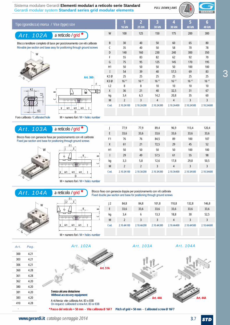
Tipo (grandezza) morsa / Vise (type) size 1 2 3 4 5 616 kN 25 kN 30 kN 30 kN 40 kN 40 kN
W 100 125 150 175 200 300
B 30 40 50 60 65 80C 35 40 50 58 70 78D 140 160 230 240 300 350F 55 83 82 62 92 70G 75 95 125 145 170 195H1 50 50 50 50 100 100I 54 39 40 57,5 69 83
K2 Ø 25 25 25 25 25 25K3 Ø 16 F7 16 F7 16 F7 16 F7 16 F7 16 F7
L2 8 8 10 10 10 10X 36 21 40 32,5 31 67kg 3,4 6,3 14,2 20,8 35 60M 2 3 4 4 3 3
Cod. 2.10.2A100 2.10.2A200 2.10.2A300 2.10.2A400 2.10.2A500 2.10.2A600
J 77,9 77,9 89,4 96,9 113,4 120,4
E 33,6 33,6 33,6 33,6 33,6 33,6
F1 76 76 84,5 89 100 107
X 61 21 72,5 29 45 52
H1 50 50 50 50 100 100
I 29 49 57,5 61 55 98
kg 3,3 5,8 12,6 17,8 29,8 50,5
M 2 2 3 4 3 3Cod. 2.10.3A100 2.10.3A200 2.10.3A300 2.10.3A400 2.10.3A500 2.10.3A600
J2 84,8 84,8 101,8 110,8 132,8 146,8
E 33,6 33,6 33,6 33,6 33,6 33,6
kg 3,4 6 13,3 18,8 30 52,5
M 2 3 3 4 3 3Cod. 2.10.4A100 2.10.4A200 2.10.4A300 2.10.4A400 2.10.4A500 2.10.4A600
Blocco fisso con ganascia fissa per posizionamento con viti calibrate Fixed jaw section and base for positioning through ground screws
Blocco fisso con ganascia doppia per posizionamento con viti calibrate Fixed double jaw section and base for positioning through ground screws
* Passo del reticolo = 50 mm - Vite calibrata Ø 16F7 Pitch of grid = 50 mm - Calibrated screw Ø 16F7
M = numero fori / M = holes number
M = numero fori / M = holes number
Art. 44A
Art. Pag.
300 4.21
303 4.21
306 4.21
360 4.28
361 4.28
362 4.20
380 4.20
381 4.20
383 4.20
410 4.28
-
Art. 102A Art. 103A Art. 104A
Art. 51A
Art. 44A
M = numero fori / M = holes numberD
H1 H1
F
IH1X
BC
Art. 360
DH1H1
BC
H1 IX
K
EJF1
DH1H1
BC
H1 IX
K
EJ2F1
A richiesta: vite calibrata Art. 83 o 83BOn request: calibrated screw Art. 83 or 83B
a reticolo / grid *Art. 102A
a reticolo / grid *Art. 103AArt. 103A
a reticolo / grid *Art. 104A
Senza alcuna dotazioneWithout accessory equipment
W
G
G
W
W
G
K3
K2
L2
Foro calibrato / Calibrated hole
Blocco tenditore completo di base per posizionamento con viti calibrate Movable jaw section and base assy for positioning through ground screws
Sistema modulare Gerardi Elementi modulari a reticolo serie Standard Gerardi modular system Standard series grid modular elements PULL DOWN JAWS

3
3.8 STD www.gerardi.it workholding catalogue 2014
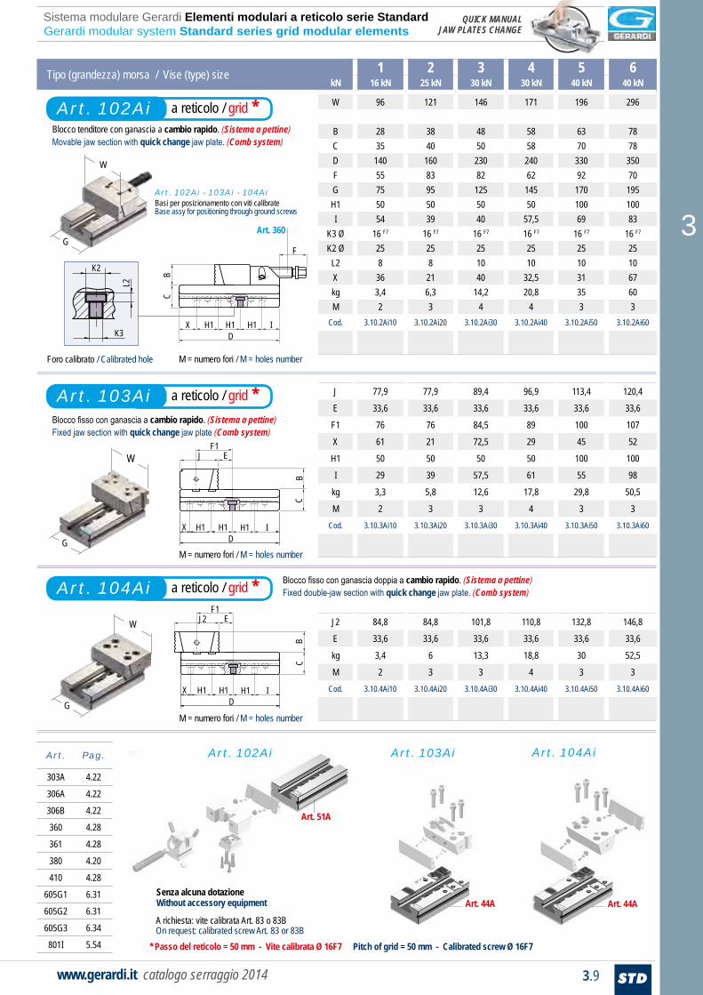
Tipo (grandezza) morsa / Vise (type) size 1 2 3 4 5 6kN 16 kN 25 kN 30 kN 30 kN 40 kN 40 kN
W 96 121 146 171 196 296
B 28 38 48 58 63 78C 35 40 50 58 70 78D 140 160 230 240 300 350F 55 83 82 62 92 70G 75 95 125 145 170 195H 40 40 50 50 100 100I 29 39 40 82,5 69 83
K1 Ø 6,5 8,5 13 13 17 17K Ø 10,5 13,5 19 19 26 26
L 4,5 5,5 8,5 8,5 17 17X 31 41 40 57,5 31 67kg 3,4 6,3 14,2 20,8 35 60M 3 3 4 3 5 5
Cod. 3.10.2i100 3.10.2i200 3.10.2i300 3.10.2i400 3.10.2i500 3.10.2i600
J 77,9 77,9 89,4 96,9 113,4 120,4
E 33,6 33,6 33,6 33,6 33,6 33,6
F 76 76 84,5 89 100 107
X 31 31 72,5 29 45 52
H 40 40 50 50 100 100
I 29 49 57,5 61 55 98
kg 3,3 5,8 12,6 17,8 29,8 50,5
M 3 3 3 4 5 5Cod. 3.10.3i100 3.10.3i200 3.10.3i300 3.10.3i400 3.10.3i500 3.10.3i600
J2 84,8 84,8 101,8 110,8 132,8 146,8
E 33,6 33,6 33,6 33,6 33,6 33,6
kg 3,4 6 13,3 18,8 30 52,5
M 3 3 3 4 5 5Cod. 3.10.4i100 3.10.4i200 3.10.4i300 3.10.4i400 3.10.4i500 3.10.4i600
Art. 102i
Art. 103i
Art. 104i
Blocco tenditore con ganascia a cambio rapido. (Sistema a pettine)Movable jaw section with quick change jaw plate. (Comb system)
Blocco fisso con ganascia a cambio rapido. (Sistema a pettine)Fixed jaw section with quick change jaw plate. (Comb system)
M = numero fori / M = holes number
M = numero fori / M = holes number
Blocco fisso con ganascia doppia a cambio rapido. (Sistema a pettine)Fixed double-jaw section with quick change jaw plate. (Comb system)
Art. Pag.
44 3.10
44A 3.10
51 3.10
51A 3.10
120A 4.12
123A 4.12
127A 4.12
230D 4.13
258 4.28
282 4.28
300A 4.22
Art. 102i Art. 103i Art. 104i
Art. 51
306A306B801IArt. 127A
230D
605G3605G2605G1
410361282360Art. 258
Art. 120A Art. 123A
Art. 44 Art. 44
380300A230D605G1605G2605G3
380303A230D605G1605G2605G3
230D
DH
LB
C
HJIX
K
EJF
DH
LB
C
H IX
K
EJ2F
Dotazione standard:■ 1 coppia di tasselli di posizionamento Art. 297 + 2 tappi Art. 291 Standard equipment:■ 1 pair of positioning key-nuts Art. 297 + 2 insert Art. 291
DH
F
IHX
BC
H
Art. 360
M = numero fori / M = holes number
G
W
W
G
G
W
K1
K
L
16H7
16H7
16H7
PIASTRE GANASCE A CAMBIO RAPIDO MANUALE
Sistema modulare Gerardi Elementi modulari serie Standard Gerardi modular system Standard series modular elements
3
3.9 STDwww.gerardi.it catalogo serraggio 2014
Tipo (grandezza) morsa / Vise (type) size 1 2 3 4 5 6kN 16 kN 25 kN 30 kN 30 kN 40 kN 40 kN
W 96 121 146 171 196 296
B 28 38 48 58 63 78C 35 40 50 58 70 78D 140 160 230 240 330 350F 55 83 82 62 92 70G 75 95 125 145 170 195H1 50 50 50 50 100 100I 54 39 40 57,5 69 83
K3 Ø 16 F7 16 F7 16 F7 16 F7 16 F7 16 F7
K2 Ø 25 25 25 25 25 25L2 8 8 10 10 10 10X 36 21 40 32,5 31 67kg 3,4 6,3 14,2 20,8 35 60M 2 3 4 4 3 3
Cod. 3.10.2Ai10 3.10.2Ai20 3.10.2Ai30 3.10.2Ai40 3.10.2Ai50 3.10.2Ai60
J 77,9 77,9 89,4 96,9 113,4 120,4
E 33,6 33,6 33,6 33,6 33,6 33,6
F1 76 76 84,5 89 100 107
X 61 21 72,5 29 45 52
H1 50 50 50 50 100 100
I 29 39 57,5 61 55 98
kg 3,3 5,8 12,6 17,8 29,8 50,5
M 2 3 3 4 3 3Cod. 3.10.3Ai10 3.10.3Ai20 3.10.3Ai30 3.10.3Ai40 3.10.3Ai50 3.10.3Ai60
J2 84,8 84,8 101,8 110,8 132,8 146,8
E 33,6 33,6 33,6 33,6 33,6 33,6
kg 3,4 6 13,3 18,8 30 52,5
M 2 3 3 4 3 3Cod. 3.10.4Ai10 3.10.4Ai20 3.10.4Ai30 3.10.4Ai40 3.10.4Ai50 3.10.4Ai60
Blocco tenditore con ganascia a cambio rapido. (Sistema a pettine)Movable jaw section with quick change jaw plate. (Comb system)
Blocco fisso con ganascia a cambio rapido. (Sistema a pettine)Fixed jaw section with quick change jaw plate (Comb system)
M = numero fori / M = holes number
M = numero fori / M = holes number
Blocco fisso con ganascia doppia a cambio rapido. (Sistema a pettine)Fixed double-jaw section with quick change jaw plate. (Comb system)
Art. Pag.
303A 4.22
306A 4.22
306B 4.22
360 4.28
361 4.28
380 4.20
410 4.28
605G1 6.31
605G2 6.31
605G3 6.34
801I 5.54
Art. 44A
Art. 51A
Art. 44A
Art. 102Ai Art. 103Ai Art. 104Ai
DH1H1
BC
H1 IX
EJF1
DH1H1
BC
H1 IX
EJ2F1
a reticolo / grid *Art. 102Ai
a reticolo / grid *Art. 103Ai
a reticolo / grid *Art. 104Ai
DH1 H1
F
IH1X
BC
Art. 360
M = numero fori / M = holes number
G
W
G
W
W
G
* Passo del reticolo = 50 mm - Vite calibrata Ø 16F7 Pitch of grid = 50 mm - Calibrated screw Ø 16F7
A richiesta: vite calibrata Art. 83 o 83BOn request: calibrated screw Art. 83 or 83B
Senza alcuna dotazioneWithout accessory equipment
K3
K2
L2
Foro calibrato / Calibrated hole
Art. 102Ai - 103Ai - 104AiBasi per posizionamento con viti calibrateBase assy for positioning through ground screws
QUICK MANUAL JAW PLATES CHANGE
Sistema modulare Gerardi Elementi modulari a reticolo serie Standard Gerardi modular system Standard series grid modular elements

3
3.10 STD www.gerardi.it workholding catalogue 2014
Tipo (grandezza) morsa / Vise (type) size 1 2 3 4 5 6G 75 95 125 145 170 195
D 140 160 230 240 300 350
kg 1.8 3.3 6.9 8 14.5 21.8Cod. 1.80.14140 1.80.24160 1.80.34230 1.80.44250 1.80.54300 1.80.64351
ELEMENTI MODULARI BASE / Supplemento extra per ogni folo calibrato + € 76 BASIC MODULAR UNITS / Extra supplement for each ground hole + € 76
Slittone base per ganascia fissaSplit base for fixed jaw
Art. 44
D 140 160 230 240 300 350
kg 2.1 3.4 8.2 11.5 20 30Cod. 1.80.13140 1.180.23160 1.80.33230 1.80.43250 1.80.53300 1.80.63350
Tipo (grandezza) morsa / Vise (type) size 1 2 3 4 5 6A 320 320 400 400 500 500
B 11 11 18 18 20 20
C 10 10 15 15 20 20
D 20 20 25 25 25 25
M M6 M8 M12 M12 M16 M16
E 9 12 18 18 24 24
F 15 15 20 20 30 30
G 6 8 12 12 16 16
kg 0.5 0.5 1.2 1.2 2 2
Cod. 3.35.81000 3.35.82000 3.35.83000 3.35.84000 3.35.85000 3.35.86000
ACCESSORIACCESSORIES
Cod. 3.51.A1000 3.51.A2000 3.51.A3000 3.51.A4000 3.51.A5000 3.51.A6000
Elemento di prolunga base per ganascia mobileBase extension for movable jaw
Art. 51
Art. 51A
Barra di tensione / Tension barArt. 358
Accessori per Art. 51 e 102A richiesta altre larghezze senza variazione di prezzoAccessories for Art. 51 and 102Other widths available on request without price change
Elemento di prolunga base a reticolo (Passo 50 mm, Ø 16)Grid (50 mm) pitch, Ø 16 base extension
D 140 160 230 240 300 350
kg 1.7 3.2 6.8 7.9 14.4 21.7Cod. 3.44.A1000 3.44.A2000 3.44.A3000 3.44.A4000 3.44.A5000 3.44.A6000
Slittone base a reticolo (Passo 50 mm, Ø 16 per blocco fisso)Split grid (50 mm) pitch, Ø 16 base for fixed section
Apertura illimitataUnlimited opening
Tavola macchina / Machine table
D
FGB EB
MA C
D
D
D
A
Sistema modulare Gerardi Elementi modulari serie Standard Gerardi modular system Standard series modular elements
Art. 44A
3
3.11 STDwww.gerardi.it catalogo serraggio 2014
AS S
B
AZ
ABI ABC
A
N
MaxAT
FAF Y W AG
N
A
C
O L X AD
FAHW Y
A
ADXLOAL
AI
C
N
ALC
AE
AD
PFWY
N
A
XLOZ
A
NAM F
YW
ADXLO
C
AN
AMWW
A
AO
N
K
O L X AD
C
O L
L
A
J
HAA G
V
L
X ADR
R
URTACAB AB Q
C
AYDE
M
RB
AAH
DEC
AG
J
RB
V
U RTIAB AB
Art. 102 pos. 1
AQ AR
ABBYMax BC
I ABC
N
A
BQArt. 355
Art. 360
Art. 365
Art. 365 - Particolare / Dettaglio
Art. 102 pos. 2
Art. 103 pos. 1
Art. 103 pos. 3
Art. 103 pos. 2
Art. 103 pos. 4
Art. 104 pos. 1 Art. 104 pos. 2
Art. 44 Art. 51
K PW W AP
N
A
ADXOAI LAL
C
Art. 102
Art. 103
Art. 104
Sistema modulare Gerardi Elementi modulari serie Standard Gerardi modular system Standard series modular elements
3
3.12 STD www.gerardi.it workholding catalogue 2014
HAA
BK
ME
B
DAYBE
BDBH BI BI BI BL
BF
BG
L
A
J
G
LLR
R
BMC
BW
BD BF
BH BI BI BI BL
A
BG
B
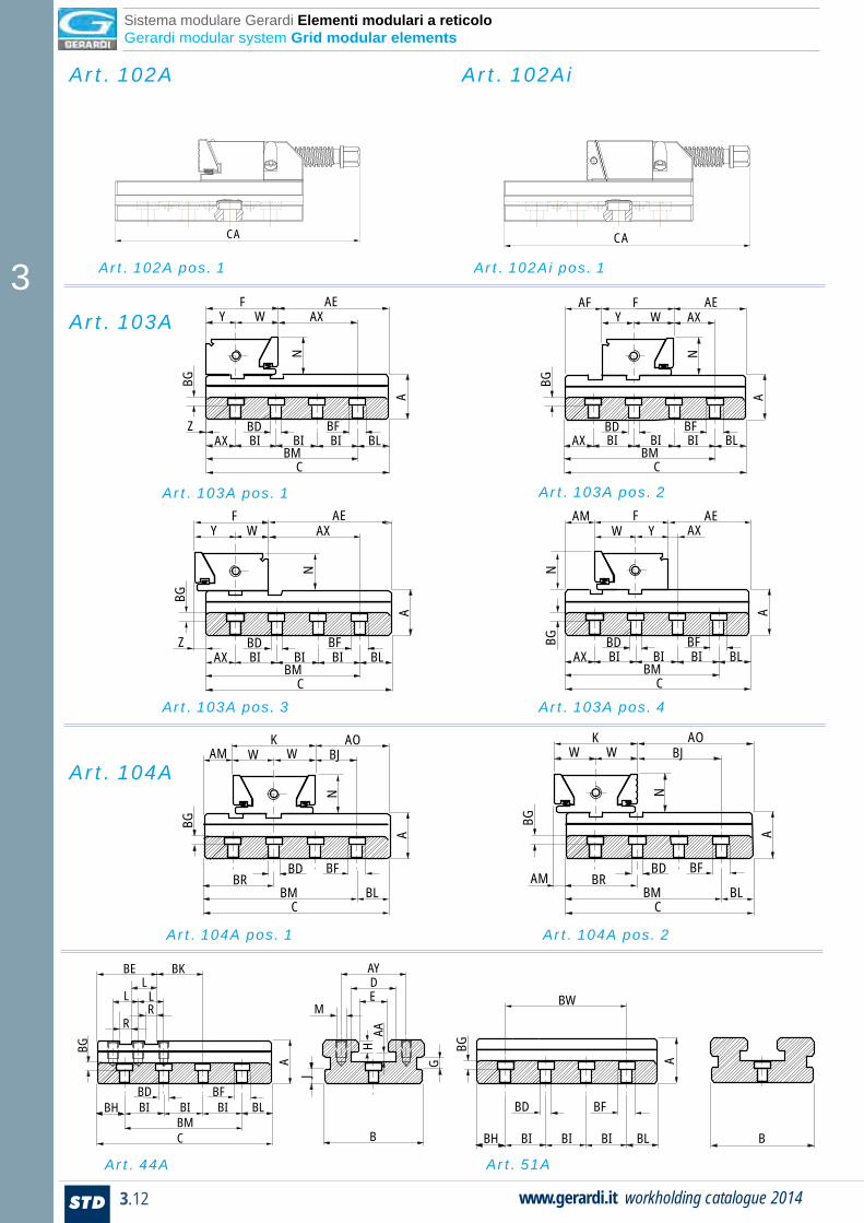
Art. 104A pos. 1 Art. 104A pos. 2
Art. 44A Art. 51A
Art. 102A pos. 1 Art. 102Ai pos. 1
Art. 103A pos. 1
Art. 103A pos. 3
Art. 103A pos. 2
Art. 103A pos. 4
AEAX
AX BI BI BI BLBD BF
BMC
WY
Z
N
A
BG
F AEAX
AX BI BI BI BLBD BF
BMC
WY
N
A
BG
FAF
AEAX
AX BI BI BI BLBD BF
BMC
Z
N
A
WY
BG
F AM AE
AX BI BI BI BLBD BF
BMC
N
A
W YBG
FAX
CA CA
AO
AMBD
BRBM BL
C
BF
K
A
BG
BJW W
N
AOAM
BDBR
BM BLC
BF
K
N
A
BG
BJW W
Art. 102A
Art. 103A
Art. 104A
Art. 102Ai
Sistema modulare Gerardi Elementi modulari a reticolo Gerardi modular system Grid modular elements

3
3.13 STDwww.gerardi.it catalogo serraggio 2014
Tipo (grandezza) morsa / Vise (type) size
mm 1 2 3 4 5 6 TolleranzaTolerance
A 35 40 50 58 70 78 - 0.02
B 75 95 125 145 170 195 - 0.02
C 140 160 230 240 300 350
D 31 41 57 70 80 90
E 21 28 41 51 61 71 + 0.02
F 77.9 77.9 89.4 96.9 113.4 120.4 - 0.04
G 9.5 9.5 11.5 11.5 17.5 17.5
H 10 10 13 15 20 20 - 0.02
I 31 41 40 57.5 31 67
J 15 15 20 20 26 26
K 84.8 84.8 101.8 101.8 132.8 146.8 - 0.04
L 32 32 36 36 44 44 - 0.02
M M10 M12 M14 M16 M20 M20
N 30 40 50 60 65 80 ± 0.02
O 43 43 46 48 53 53
P 33.6 33.6 33.6 33.6 33.6 33.6 ± 0.02
Q 29 49 157.5 61 55 98
R 16 16 16 16 16 16 H7
S 100 125 150 175 200 300
T 6.5 8.5 13 13 17 17
U 10.5 13.5 19 19 26 26
V 4.5 5.5 8.5 8.5 17 17
W 42.4 42.4 50.9 55.4 66.4 73.4 ± 0.02
X 44 44 48.5 53 56 63 ± 0.02
Y 35.5 35.5 35.5 41.5 47 47 ± 0.02
Z 0.5 0.5 0.5 1.5 2 2
AA 10 10 12 18 18 18 + 0.04
AB 40 40 50 50 100 100
AC 76 76 84.5 89 100 107 - 0.02
AD 21 41 99.5 103 147 190
AE 62.6 82.6 141.6 144.6 188.6 231.6
AF 31.5 31.5 35.5 35.5 42 42
AG 30.6 50.6 105.1 108.6 144.6 187.6
AH 69.5 89.5 153.5 158.5 208 258
AI 7.4 7.4 12.9 15.4 21.4 28.4
AJ 36 36 40.5 45 48 55 ± 0.1
AK80 80 120 120 160 240
± 0.013 x Ø12 3 x Ø12 4 x Ø12 4 x Ø12 3 x Ø12 4 x Ø12
AL 111 111 122.5 129 145 152
AM 24.6 24.6 23.6 20.6 22.6 15.6
AN 37.5 57.5 117.5 122.5 164. 214
AO 30.6 50.6 105.1 108.6 144.6 187.6
AP 62.6 82.6 141.6 144.6 188.6 231.6
AQ 50 60 80 90 100 120
AR 32 51 48 68 78 94
AS 28 49 102 82 122 136
AT 55 68 82 62 92 70
AU 45 38 47 27 52 45
mm 1 2 3 4 5 6 TolleranzaTolerance
AV 29 49 107.5 111 155 198
AW 111 111 122.5 129 145 152
AX 33.6 33.6 33.6 33.6 33.6 33.6 ± 0.02
AY 50 62 88 100 120 133
AZ 62 80 90 116 138 184
BABB 20 32 50 50 76 90
BC 45 38 47 32 52 55
BD 16 16 16 16 16 16 F7
BE 75 75 82 84 97 97
BF 20.5 25 25 25 25 25
BG 8 8 10 10 10 10
BH 36 21 40 32.5 31 67
BI 50 50 50 50 50 50 ± 0.01
BJ 33.6 33.6 33.6 33.6 33.6 33.6 ± 0.02
BK 36 36 40.5 45 48 55 ± 0.01
BL 29 39 40 57.5 69 83
BM 111 121 190 182.5 231 267
BN 320 320 400 400 500 500
BO 11 11 18 18 20 20
BP 24.6 24.6 23.1 20.6 22.6 15.6
BQ 35 35 38 40 45 45
BR 67 67 74 76 89 89
BS 12 12 12 12 12 12 F7
BT 20 20 20 20 20 20
BU 8 8 8 8 8 8
BV 31 31 42.5 49 65 72
BW100 100 150 150 200 200
± 0.013 x Ø16 3 x Ø16 4 x Ø16 4x Ø16 3 x Ø16 3 x Ø16
BX 10 10 15 15 20 20
BY 10 10 15 20 25 30
BZ 40 40 40 40 40 40 ± 0.01
CA 195 228 312 302 392 420
CBCC 20 20 25 25 25 25
CD M6 M8 M12 M12 M16 M16
CE 9 12 18 18 24 24
CF 15 15 20 20 30 30
CG 4 5 12 12 16 16
Tipo (grandezza) morsa / Vise (type) size
Sistema modulare Gerardi Elementi modulari serie Standard Gerardi modular system Standard series modular elements
3
3.14 STD www.gerardi.it workholding catalogue 2014
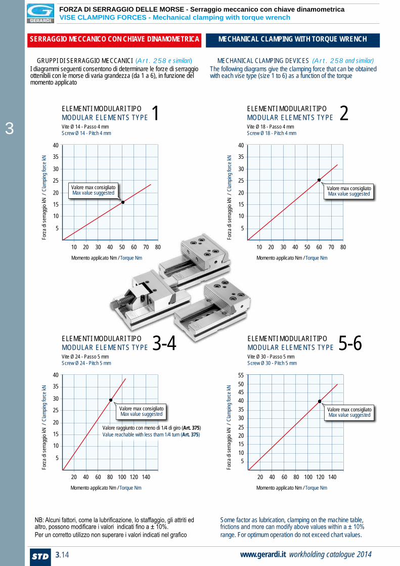
ELEMENTI MODULARI TIPOMODULAR ELEMENTS TYPEVite Ø 14 - Passo 4 mmScrew Ø 14 - Pitch 4 mm
1
ELEMENTI MODULARI TIPOMODULAR ELEMENTS TYPEVite Ø 30 - Passo 5 mmScrew Ø 30 - Pitch 5 mm
5-6
ELEMENTI MODULARI TIPOMODULAR ELEMENTS TYPEVite Ø 18 - Passo 4 mmScrew Ø 18 - Pitch 4 mm
2
ELEMENTI MODULARI TIPOMODULAR ELEMENTS TYPEVite Ø 24 - Passo 5 mmScrew Ø 24 - Pitch 5 mm
3-4
GRUPPI DI SERRAGGIO MECCANICI (Art. 258 e similari)I diagrammi seguenti consentono di determinare le forze di serraggio ottenibili con le morse di varia grandezza (da 1 a 6), in funzione del momento applicato
MECHANICAL CLAMPING DEVICES (Art. 258 and similar)The following diagrams give the clamping force that can be obtained with each vise type (size 1 to 6) as a function of the torque
NB: Alcuni fattori, come la lubrificazione, lo staffaggio, gli attriti ed altro, possono modificare i valori indicati fino a ± 10%.Per un corretto utilizzo non superare i valori indicati nel grafico
SERRAGGIO MECCANICO CON CHIAVE DINAMOMETRICA MECHANICAL CLAMPING WITH TORQUE WRENCH
Some factor as lubrication, clamping on the machine table, frictions and more can modify above values within a ± 10% range. For optimum operation do not exceed chart values.
40
35
30
25
20
15
10
5
10 20 30 40 50 60 70 80
Forza
di se
rragg
io kN
/ C
lampin
g for
ce kN
Momento applicato Nm / Torque Nm
Valore max consigliatoMax value suggested
Momento applicato Nm / Torque Nm
20 40 60 80 100 120 140
55504540353025
5
Forza
di se
rragg
io kN
/ C
lampin
g for
ce kN
201510
Valore max consigliatoMax value suggested
20 40 60 80 100 120 140
Forza
di se
rragg
io kN
/ C
lampin
g for
ce kN
Momento applicato Nm / Torque Nm
Valore max consigliatoMax value suggested
Valore raggiunto con meno di 1/4 di giro (Art. 375)Value reachable with less tham 1/4 turn (Art. 375)
40
35
30
25
20
15
10
5
10 20 30 40 50 60 70 80
Forza
di se
rragg
io kN
/ C
lampin
g for
ce kN
Momento applicato Nm / Torque Nm
Valore max consigliatoMax value suggested
40
35
30
25
20
15
10
5
FORZA DI SERRAGGIO DELLE MORSE - Serraggio meccanico con chiave dinamometrica VISE CLAMPING FORCES - Mechanical clamping with torque wrench