mortar in tension - university of warwick · mortar strength. expressions are quoted for optimum...
TRANSCRIPT

- 1 -
Chapter 1
Strength of cementitious mortars: a
literature review with special reference to weak mortars in
tension
1.1 Abstract
Cementitious materials are commonly used for the construction of low-cost water storage tanks in developing countries. For this purpose
an understanding of their properties, particularly tensile, is important.
A literature review is undertaken, starting with factors determining
mortar strength. Expressions are quoted for optimum water content varying with determined for each sand:cement ratio; this content will depend on the compaction method being used.
The review is followed by some analytical work based on available data, suggesting that sand:cement ratios of around 6:1 are optimal
with respect to materials cost, provided certain strength relationships suggested from existing data hold.
- 2 -
Strength of cementitious mortars: a literature review with special
reference to weak mortars in tension ................................................. 1
1.1 Abstract ................................................................................ 1
1.2 Introduction.......................................................................... 2
1.3 Literature Review .................................................................. 3
1.3.1 Mortar components and failure ....................................... 3
1.3.2 Sand-cement ratio .......................................................... 4
1.3.3 Voids and strength ......................................................... 4
1.3.4 Water-cement ratio ......................................................... 5
1.3.5 Pores and air content ...................................................... 7
1.3.6 Compaction & cement rheology ....................................... 8
1.3.7 Determination of optimum water-cement ratio .............. 10
1.3.8 Curing & Shrinkage ...................................................... 11
1.3.9 Drying and Strength ..................................................... 12
1.3.10 Data from literature ................................................... 13
1.4 Strength Modelling and Mix Proportioning .......................... 17
1.4.1 Simple Model and optimisation ..................................... 17
1.4.2 Model application ......................................................... 19
1.4.3 Modifications to thickness term .................................... 24
1.4.4 Labour Content ............................................................ 25
1.5 Conclusions ........................................................................ 21
1.6 Reference List ..................................................................... 23
1.2 Introduction
The Development Technology Unit has an interest in work on low cost rainwater storage tanks for developing country applications. In developing countries applications, labour is relatively cheap compared
to materials. In this case, techniques that allow the substitution of mechanical work for materials are likely to be attractive.
Many designs for tanks using cementitious materials exist at present, and the majority of these employ rich mortars (low sand-cement ratios). In some cases the wall thickness also seems excessive.
However, fieldworkers have observed the successful use of low-cement mortars by local workers. This offers one avenue for exploration, as
cement is significantly more expensive than sand (or other fine aggregates), hence using larger quantities of a weaker mix may provide a lower cost product.
A mortar will have a series of properties, including its ultimate compressive and tensile strengths (measured as stresses), Young’s Modulus, Poisson’s ratio etc. Of these, there is often a relationship
between compressive and tensile strength (and compressive is easier to measure). Depending on the tank design, we are largely interested
in the tensile strength, though certain designs will make compressive strength important.
- 3 -
To simplify consideration of the mortar, it will initially be considered as consisting of water, fine aggregate (sand), and cement only, without
admixtures.
1.3 Literature Review
The range of factors influencing the strength of cementitious products is legion. Included within these are the physical and
chemical characteristics of the cement, aggregate, and water, the mixing environment and subsequent curing conditions. To address all
of these experimentally and exhaustively is not feasible – some selection of significant variables is required. To this end a review of current literature was undertaken, with the additional aim of avoiding
unnecessary duplication of existing results.
1.3.1 Mortar components and failure
A set mortar will consist of four components:
[1] Cement1. [2] Sand.
[3] Water. [4] Air.
Mortar and concrete fail by crack propagation through the cement paste, rather than failure of the aggregate (Whittmann, 1983). There are some exceptions to this, but given the use of normal-weight
aggregates in lean mortars it is highly unlikely that aggregate failure will occur.
There is at least one significant difference between compressive and
tensile loading: a crack area in tension cannot contribute any strength to the mortar, whilst two faces in compression can still transfer some
load.
A compressive load can cause tensile forces to occur in regions of the material (Orowan, 1948). For biaxial loading it has been shown that,
to give the same tensile force around a crack, a compressive force eight times that of the tensile loading would be required. The cracks of
highest stress in uniaxial loading would lie at 45o to the axis. These findings accord with the typical ratios for concretes (tensile strength of around 10% of the compressive), and failure geometries, though the
ratio of compressive: tensile strength varies with a number of factors. However, the assumptions in this model do provide an oversimplification of the actual situation: the model assumes a
homogenous material with a large number of identically sized cracks in all orientations.
1 Simplifying the situation by neglecting the presence of any unhydrated cement in
the mortar.
- 4 -
Another interesting point is that surface finish will have a more significant effect for failure in flexure: a rough surface will contribute
stress concentration effects in the area of greatest stress.
1.3.2 Sand-cement ratio
The received wisdom is that increasing the cement content of a concrete will increase its strength. Whilst in many practical cases this is true, it arises from secondary effects. Certainly, for concretes of
strengths above 35MPa, increasing the aggregate content whilst holding the water-cement ratio constant will lead to an increase in
strength (Neville, 1995). There are several possible explanations for this, but the most plausible is as follows:
Concrete fails through crack propagation. Cracks are initiated in
either the matrix or the matrix-aggregate bonds. Failure is statistical, so increasing the amount of matrix will raise the probability of flaws
being present that will cause crack propagation at a given stress. If all other factors are held constant, increasing the quantity of aggregate per unit volume of concrete will reduce the probability of crack-
initiating features, hence giving a stronger concrete.
However, it is extremely difficult to hold these other factors constant.
In addition, at extremely high sand: cement ratios (around 10:1) there will be insufficient paste to fill the voids between the aggregate particles. For mortars in tension the load must be transferred through
the cement matrix. Reducing the amount of matrix taking the load will reduce the strength.
Cement is considerably more expensive per unit mass than sand
(ratios of between 20:1 and 70:1 have been recorded in developing countries), so reduction of the cement content is desirable if possible.
1.3.3 Voids and strength
If we take a cementitious material of given sand-cement ratio, the
strength is fundamentally determined by the volume of voids in it (Neville, 1995). There are two potential effects:
Increase in stress from reduction in material withstanding load.
Stress concentration effects.
The source of these voids may be:
Free water.
Air voids arising from incomplete compaction.
For normal concretes, the design is for a high degree of compaction
(and corresponding low air voids content of around 1% by volume), and hence the water: cement ratio will dominate the strength. However, for mixes that are more difficult to work, such as lean
mortars, the presence of air voids will rise, and their effect on strength will become non-negligible.

- 5 -
1.3.4 Water-cement ratio
As mentioned above, in much concrete work the critical factor influencing strength is the water-cement ratio, as famously encapsulated in Abram’s rule. This states that the strength of concrete
falls monotonically as water-cement ratio rises. A more accurate formulation would be:
“The strengths of comparable concretes depend solely on their water-cement ratios regardless of their compositions.”
(Popovics, 1998)
The conditions for comparable concretes are given in Table 1.
Table 1: Conditions for “comparable” concretes
1. The strength-developing capabilities of the cements used are identical.
2. The quantities and strength-influencing effects of the admixtures used are identical.
3. The concrete specimens are prepared, cured and tested under the same conditions.
4. The concrete ingredients (cement, water, aggregate particles,
admixtures) are distributed uniformly in the concrete.
5. The air contents are the same in the concretes, the air voids are distributed uniformly in the concrete, and none of the
voids is too large for the size of the specimens.
6. The aggregate particles are stronger than the matrix; that is,
the fracture propagates more in the matrix than in the particles.
7. The bond between the aggregate surfaces and matrix is equally
strong in the concretes compared and is strong enough to transfer the major portion of stresses in the matrix to the
aggregate before the concrete is crushed by the load.
8. The strength-affecting physical and/or chemical processes in the concretes (drying, aggregate reactivity, etc), beyond the
cement hydration, are not overwhelming (cracking, etc.) and are the same.
9. The nonhomogeneity or composite nature of concrete, the
origin of which is in the differing characteristics of matrix and aggregate particles, affects the strength of the compared
concretes to the same extent.
10. The contribution of the aggregate skeleton, resulting from interlocking of the aggregate particles during loading, to the
concrete strength, is the same in the various concretes.
(Popovics, 1998)

- 6 -
On closer examination this reduces to a truism along the lines of: “if all other factors influencing strength are held constant, the only factor
determining concrete strength is water content.” In particular for our case, point 5 cannot be guaranteed. At this point the question arises
as to what extent Abram’s law will be useful.
Abram’s law has been found by experiment to fit this algebraic form:
0
/
0
w c
As
B
Equation 1.1
Where s is the strength, A0 and B0 are constants (Bo>1), and w/c is the water-cement ratio. A0 has units of stress, and Bo is
dimensionless. Values of B0 have been found both for compressive and tensile strengths (both flexural and splitting for tension2) as shown in Table 2.
Table 2: Typical values of Bo for concretes (Popovics, 1998)
Strength type Bo
Natural aggregates Lightweight aggregates
Compressive 20 7
Flexural 7 3
Splitting 8 3
It is of particular interest to notice that tensile strength (by either
measure) is less sensitive to water-cement ratio than compressive strength.
In general, cementitious materials require water for two functions:
1. To hydrate the cement particles, leading to setting and hardening of the material.
2. To provide some lubrication such that the material is sufficiently fluid to be moved into the required shape, and for the expulsion of air.
This means that for mortars there should always be some water in excess of that for hydration of the cement.
With insufficient or no lubricating water, the material will have a certain quantity of air voids from incomplete compaction. The presence of these voids leads to a reduction in strength of the mortar,
as is covered in 1.3.5.
Perhaps a more sensible approach is not to try to use Abram’s rule
as a mathematical expression, but to understand the general principle that, for given concretes with other strength-determining factors not varying excessively, the water-cement content is the most significant
factor in determining strength.
2 Splitting strength is determined by the Brazilian cylinder test, whilst flexural is
determined by several-point loading of a beam in bending.

- 7 -
1.3.5 Pores and air content
The presence of air pores acts to reduce the strength of concrete. There are several possible formulae to represent this effect:
10 a
rel
o
ff
f
Equation 1.2
(Popovics, 1998)
In this case frel is a relative mechanical property, defined as f divided by fo, the property for the material with zero voids, a is the volume
fraction occupied by air voids, and is an experimentally determined constant. The above relationship is that developed for the strength
variation with porosity for polycrystalline bodies with air-filled voids.
Typical values for are also available:
Concrete Type
Compressive strength of normal-weight
concretes up to 30% air voids between 7
and 90 days age.
0.0384
Flexural strength 0.0232
Table 3: Typical values of (Popovics, 1998).
This was modified for cementitious materials by Popovics to:
1 10 cr
a
a
rel
o cr
f af
f a
Equation 1.3
Where acr<100% is the critical air voids at which the physical
property goes to zero (%), a< acr as the actual air voids content (%). The first part of the right-hand side of Equation 1.3 is intended to
account for the material removal effect, and the second part for stress
concentrations. Note that will take different values for this
expression than in Equation 1.2.
Assuming the air void content can be varied independent of the water-cement ratio, it should be possible to combine this with some
form of Abram’s rule or similar, to give:
0
/
0
1 10 cr
a
a
w c
cr
A as
B a
Equation 1.4
There may be later complications arising from the variation in stress concentration factor with stress level. If Equation 1.4 holds,
correlations might be possible between strength, initial air content and compaction method.
- 8 -
1.3.6 Compaction & cement rheology
Compaction normally involves the application of mechanical work to a mix in order to reduce the air content. As covered above, this then improves the strength of the finished material. Techniques used for
compaction include:
Static or slowly varying loading.
Rapidly varying (e.g. impulsive) loading.
Application of external vibration (e.g. via mould walls).
Insertion of a vibrating element.
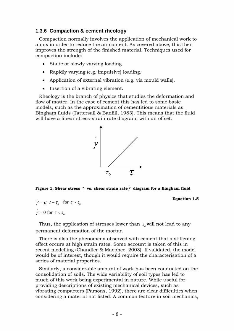
Rheology is the branch of physics that studies the deformation and flow of matter. In the case of cement this has led to some basic models, such as the approximation of cementitious materials as
Bingham fluids (Tattersall & Banfill, 1983). This means that the fluid will have a linear stress-strain rate diagram, with an offset:
.
o
..
o
Figure 1: Shear stress vs. shear strain rate.
diagram for a Bingham fluid
.
.
for
0 for
o o
o
Equation 1.5
Thus, the application of stresses lower than owill not lead to any
permanent deformation of the mortar.
There is also the phenomena observed with cement that a stiffening effect occurs at high strain rates. Some account is taken of this in
recent modelling (Chandler & Macphee, 2003). If validated, the model would be of interest, though it would require the characterisation of a
series of material properties.
Similarly, a considerable amount of work has been conducted on the consolidation of soils. The wide variability of soil types has led to
much of this work being experimental in nature. While useful for providing descriptions of existing mechanical devices, such as vibrating compactors (Parsons, 1992), there are clear difficulties when
considering a material not listed. A common feature in soil mechanics,

- 9 -
stabilised soil research and cement production is that there exists an optimum moisture content. With dry soils, high friction exists between
particles. As the moisture content increases, there is an initial absorption into soil particles (if they are porous), and then an
adsorption of a thin layer around the soil particle surface. This layer can act as a lubricant, leading to the increase in workability mentioned in 1.3.4 above. Above an optimum point, there is a swelling
effect as the moisture separates the particles, which reduces both density and strength.
The determination of this optimum water content for different soils
has also been linked to other quantities, such as the plastic limit of the soil (Hausmann, 1990). This is an interesting point to note, as it
may prove to be of use when generating practical recommendations. It should be easier to determine the water content for a particular type of commonly-tested mortar behaviour (e.g. slump), than to accurately
measure other properties more commonly used in design calculations (such as specific surface).
Mechanical vibration compaction has been used successfully with ferrocement products (Sharma, 1983), with strength gains of around 20% over hand compaction quoted. In this case, the only technical
details given were that the machine could run on single-phase 300W power. The images in the article indicate the type of machine used:
(a) (b)
Figure 2: Vibrating compactor diagram (a) and in use (b).
Similar vibro-pressing techniques have been used in Poland (Walkus, 1981). In this case the suggestion is made that vibration
frequencies above 100Hz be used. For optimum strength a linear relationship between vibration intensity and travelling speed of the
machine (a surrogate for inverse of duration of vibration), with intensity defined as:
2 3
mI A n
Equation 1.6
Where mA is the amplitude of vibration, and n the frequency of
vibration. This also includes the finding that wetter mixes require less compaction, as would be expected.
- 10 -
For a constant intensity then, Equation 1.6 implies that the
sensitivity of n to mA will be –1.5 i.e. a 1% increase in frequency will
allow a 2 3 % reduction in amplitude.
However, other researchers (Hausmann, 1990) have suggested using a frequency only just above the natural frequency of the material, and
large amplitude is more effective than using high frequency and low amplitude.
Research on roller compacted concrete (extremely dry concrete that is difficult to compact by normal means, used in pavements, water control structures etc) (Kokobu et al., 1996), varied both frequency of
vibration (75-150Hz), and the acceleration used. Several results were obtained:
For a given compaction effort (J/l) and peak acceleration,
frequency had little effect on compaction achieved.
For a given compaction effort and frequency, increasing the acceleration increased the compaction.
Increasing the acceleration increased the final compaction achieved, though there was negligible increase above 3g
acceleration.
Increased compactive effort increased final compaction
asymptotically. Full compaction was achieved at around 100 J/l, which is of the same order as that for stabilised soil compaction (200 J/l).
There seems to be some variation in frequencies being recommended: lower limits of 100 Hz from one source (Walkus, 1981), whilst another quotes common practise as using around 35-50 Hz
(Hausmann, 1990), and other findings indicate little effect from varying frequency (Kokobu et al., 1996).
1.3.7 Determination of optimum water-cement ratio
Knowing that excessive water content will lead to a reduction in
strength, but that insufficient gives poor workability, a method for determining the optimum water content would obviously be desirable.
A method that takes account of the quantity of sand present is
particularly important when considering lean mixes (Lydon, 1982). One approach previously employed is based on apportioning water for the two purposes given above: an amount to hydrate the cement, and
a second quantity to lubricate the aggregate, based on its specific surface (Thanh, 1991). This can be represented algebraically:
w a a c cm m w m w Equation 1.7
- 11 -
Where wm is the optimum mass of water,
am and cm the masses of
aggregate and cement, and aw and
cw are fractions.
Two methods are quoted for estimating aw , one with water optimum
water content varying with the fineness modulus, and the other varying with the square root of the specific surface:
The first method for determining aw is:
expaw a bm Equation 1.8
a and b are constants depending on the desired workability, and m
is the fineness modulus3. (Values of a=0.215 and b=0.19 are given for one consistency, and a=0.236 and b=0.18 for another.)
Another method uses:
.034a ow s w Equation 1.9
Where s is the specific surface, and wo a constant fraction fixed by the grading of the aggregate; in the Thanh article, the two figures
quoted for wo are .02 for continuous grading and .015 by mass for gradual grading. The specific surface (s) of sands used by Thanh
ranges from 4.8 to 8.2 m2/kg, leading to aw values of around 0.09-
0.11.
T he consistent feature in both these expressions is that finer
aggregate requires more water.
1.3.8 Curing & Shrinkage
Cement sets hydraulically – it requires water. Curing normally
consists of controlling the humidity of the product environment, and possible wetting. Work on cement-stabilised soil blocks has indicated
the importance of curing on strength, with up to six times greater strength for good quality curing compared to dry conditions (Kerali & Thomas, 2002). Loss of water from cementitious materials is
associated with shrinkage. This water loss can come from continued hydration of the cement (leading to autogenous shrinkage, also known
as self-desiccation), or from surface losses.
The water present in concrete may be categorised as follows:
Free water held in capillaries beyond the range of the surface
forces in the solid phase.
3 Fineness modulus is an empirical factor obtained by adding the total percentages
of a sample of the aggregate retained on each of a specified series of sieves, and dividing the sum by 100. A lower number indicates a finer aggregate, whilst a high
value indicates a coarse aggregate.
- 12 -
Gel water, which may be either:
- Held by the surface forces of gel particles: adsorbed water.
- Held between the surfaces of certain planes in a crystal: interlayer water.
Chemically bonded water forming a definite part of the hydrated compounds.
With concrete samples there is no shrinkage associated with the loss of at least some free water. There are some interactions with water
quantity though – a higher w/c ratio implies more pores, and thus greater shrinkage potential.
Curing temperature has an effect on the strength development of
cement products. In general, higher temperatures for curing give more rapid initial strengths, but lower long-term strength. This then raises the question as to whether laboratory testing at Warwick will give
significantly different results to those that will be experienced in the tropics. However, experimental data suggests this will not be the case:
28-day strengths of concrete samples varied by only 5% between curing temperatures of 10oC and 50oC (Kim et al., 2002).
1.3.9 Drying and Strength
A series of tests conducted on rich mortars with drying indicate that drying significantly reduces the flexural strength, but that this
strength is then recovered by a relatively short period of rewetting (Hotta & Takiguchi, 1995). This effect was maintained over a range of wetting and drying regimes, and a range of water contents.
Surface cracking was observed, with observations of crack “healing” on rewetting. The presence of the cracks was interpreted as indicating
that prestrains were being fully relaxed, though this is not necessarily true.
It is possible that the effects would be greater for stress in flexure.
Because in flexure the higher tensile stresses occur at the specimen surface, the material will thus be weakened at the areas of greatest
stress, and have stress concentration elements introduced in those areas.
The implications for mortar tanks could be significant. Current
practice generally involves the use of a cement slurry to line the inside of a tank, to prevent leakage. If this drying-weakening effect persists, then it might be preferable to use the slurry on the outside of the
tank, to try and maintain a wet environment for the mortar. There is a potential problem with this approach –a slurry coating on the inside of
the tank will helpfully be driven into cracks by the water pressure, whilst one on the outside would be pushed away from the mortar.

- 13 -
1.3.10 Data from literature
1.3.10.1 Mortar Strength and Abram’s Law
Work on Abram’s law has been conducted with mortars as well as
with concrete (Appa Rao, 2001). In the Rao article there is an attempt to validate Abram’s law as applied to mortars. Whilst appearing fairly conclusive in general, there are several areas left uncovered. The
sand-cement ratios are not changed significantly (only ratios of 2:1, 2.5:1 and 3:1 are used). This is a less impressive demonstration than that for concrete, where aggregate: cement ratios commonly change
from 4:1 to 10:1.
The only results presented graphically in the article are those for
compressive strength, such as that shown below: 28-day compressive strength with w/c ratio
0
5
10
15
20
25
30
35
40
45
50
0.25 0.3 0.35 0.4 0.45 0.5 0.55 0.6 0.65 0.7
w/c
Co
mp
ressiv
e s
tren
gth
(M
Pa)
s/c 1:2 s/c 1:2.5 s/c 1:3
Figure 3: Data from Rao: 28-day compressive strength with water-cement ratio
Whilst this seems fairly convincing when quoted in the article, one obvious departure from Abram’s law is the drop in strength at low
water: cement ratios ( / 0.35w c ). The data for tensile strength
demonstrates a similar feature:

- 14 -
Tensile splitting strength with water-cement at 28 days
0
0.5
1
1.5
2
2.5
3
0.25 0.3 0.35 0.4 0.45 0.5 0.55 0.6 0.65 0.7
Water-cement ratio
Te
ns
ile S
tre
ng
th (
MP
a)
s/c 1:2 s/c 1:2.5 s/c 1:3
Figure 4: Data from Rao on 28-day tensile strength with water-cement ratio
For each of the series, some data was missing at low water:cement ratios, as the samples failed without being measured. This implies a significant drop in strength at water-cement ratios below the lowest
indicated (0.35 for the 1:2 and 1:2.5 mixes, and 0.45 for the 1:3 mix).
As can be seen, this data does show some form of inverse relationship between strength and water content. However, the
goodness of curve fit obtained using other relationship types is as good, if not better than that of Abram’s law as given in Equation 1.1.
The influence of the change in sand: cement ratio is also interesting: the difference in compressive strength between ratios of 2 and 2.5 is small compared to that between 2.5 and 3. There is a less significant
variation in tensile strength.
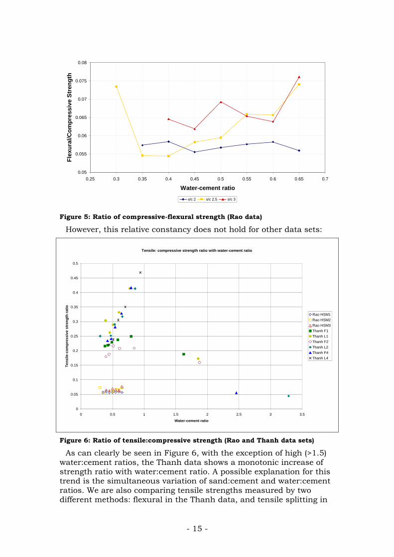
There is a considerable difference between the compressive and tensile strengths: the Rao data give tensile strength as only around 5-
6% of the compressive. This is clearly shown in Figure 5 where it may be noted that the ratio of tensile to compressive strength is fairly
constant over a wide range of water-cement ratios.
- 15 -
Variation in flexural: compressive strengths
0.05
0.055
0.06
0.065
0.07
0.075
0.08
0.25 0.3 0.35 0.4 0.45 0.5 0.55 0.6 0.65 0.7
Water-cement ratio
Fle
xu
ral/
Co
mp
ressiv
e S
tren
gth
s/c 2 s/c 2.5 s/c 3
Figure 5: Ratio of compressive-flexural strength (Rao data)
However, this relative constancy does not hold for other data sets:
Tensile: compressive strength ratio with water-cement ratio
0
0.05
0.1
0.15
0.2
0.25
0.3
0.35
0.4
0.45
0.5
0 0.5 1 1.5 2 2.5 3 3.5
Water-cement ratio
Te
ns
ile
-co
mp
res
siv
e s
tre
ng
th r
ati
o
Rao HSM1
Rao HSM2
Rao HSM3
Thanh F1
Thanh L1
Thanh F2
Thanh L2
Thanh F4
Thanh L4
Figure 6: Ratio of tensile:compressive strength (Rao and Thanh data sets)
As can clearly be seen in Figure 6, with the exception of high (>1.5)
water:cement ratios, the Thanh data shows a monotonic increase of strength ratio with water:cement ratio. A possible explanation for this trend is the simultaneous variation of sand:cement and water:cement
ratios. We are also comparing tensile strengths measured by two different methods: flexural in the Thanh data, and tensile splitting in

- 16 -
the Rao data. It is generally found that tensile strength is considerably lower than compressive.
1.3.10.2 Mortar Strength and Sand-cement ratio
A series of mortars were made and tested, with water content
determined by the method outlined in 1.3.7 (Thanh, 1991). The data from this is shown below:
0.00
2.00
4.00
6.00
8.00
10.00
12.00
14.00
16.00
0 5 10 15 20 25 30
Sand: cement
Fle
xu
ral
str
en
gth
(M
Pa)
C1 D1 C2 D2 C4 D4
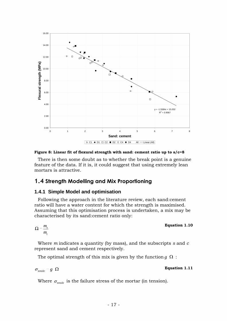
Figure 7: Flexural strength with sand:cement ratio
The letters or indicate continuous (C) or discontinuous (D) grading of sand used4, whilst the number 1,2 or 4 indicates the maximum
particle size in mm. As can be seen on the plot, the inter-series differences are sufficiently small that we may treat all the series as
one data set.
There appears to be a distinct break point at strengths of around 5~6MPa, beyond which the strength decreases less rapidly with sand:
cement ratio. If these high sand: cement ratios are excluded from the data set, there appears to be a linear relationship between strength
and sand:cement ratio:
4 In continuous grading particles of a spectrum of sizes are included, whilst in
gradual particles are of discrete sizes.
- 17 -
y = -1.5584x + 15.032
R2 = 0.9067
0.00
2.00
4.00
6.00
8.00
10.00
12.00
14.00
16.00
0 1 2 3 4 5 6 7 8
Sand: cement
Fle
xu
ral
str
en
gth
(M
Pa)
C1 D1 C2 D2 C4 D4 All Linear (All)
Figure 8: Linear fit of flexural strength with sand: cement ratio up to s/c=8
There is then some doubt as to whether the break point is a genuine feature of the data. If it is, it could suggest that using extremely lean
mortars is attractive.
1.4 Strength Modelling and Mix Proportioning
1.4.1 Simple Model and optimisation
Following the approach in the literature review, each sand:cement
ratio will have a water content for which the strength is maximised. Assuming that this optimisation process is undertaken, a mix may be
characterised by its sand:cement ratio only:
s
c
m
m
Equation 1.10
Where m indicates a quantity (by mass), and the subscripts s and c
represent sand and cement respectively.
The optimal strength of this mix is given by the function g :
tensile g Equation 1.11
Where tensile
is the failure stress of the mortar (in tension).

- 18 -
For a plate of unit area in bending the stress is inversely
proportional to the square of plate thickness (t) (2
1
t), so the
minimal thickness will correspond to:
2
1g
t
Equation 1.12
As a first approximation, we take the thickness to be proportional
only to the combined volumes of sand and of cement present in the mix:
c s
c s
m mt
Equation 1.13
So:
1c
c s
t m
Equation 1.14
Using Equation 1.12 and Equation 1.5 gives:
2
1
1c
c s
g
m
Equation 1.15
Solving for amount of cement:
1c
c s
km
g
Equation 1.16
Where k is a constant based on tank geometry.
Taking the cost of mortar as being equal to the cost of cement and sand:
m c c s s
c c s
C m c m c
m c c
Equation 1.17
And setting s
c
c
c, the sand:cement cost ratio ( 1 )
1m c cC m c Equation 1.18
So
- 19 -
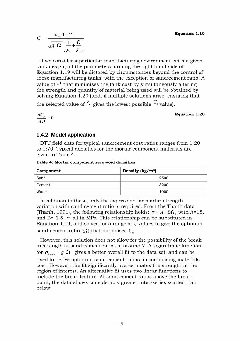
1
1
c
m
c s
kcC
g
Equation 1.19
If we consider a particular manufacturing environment, with a given tank design, all the parameters forming the right hand side of
Equation 1.19 will be dictated by circumstances beyond the control of those manufacturing tanks, with the exception of sand:cement ratio. A
value of that minimises the tank cost by simultaneously altering the strength and quantity of material being used will be obtained by solving Equation 1.20 (and, if multiple solutions arise, ensuring that
the selected value of gives the lowest possible mCvalue).
0mdC
d
Equation 1.20
1.4.2 Model application
DTU field data for typical sand:cement cost ratios ranges from 1:20 to 1:70. Typical densities for the mortar component materials are given in Table 4.
Table 4: Mortar component zero-void densities
Component Density (kg/m3)
Sand 2500
Cement 3200
Water 1000
In addition to these, only the expression for mortar strength
variation with sand:cement ratio is required. From the Thanh data (Thanh, 1991), the following relationship holds: A B , with A=15,
and B=-1.5, all in MPa. This relationship can be substituted in
Equation 1.19, and solved for a range of values to give the optimum
sand-cement ratio ( ) that minimises mC .
However, this solution does not allow for the possibility of the break in strength at sand:cement ratios of around 7. A logarithmic function
for tensile g gives a better overall fit to the data set, and can be
used to derive optimum sand:cement ratios for minimising materials
cost. However, the fit significantly overestimates the strength in the region of interest. An alternative fit uses two linear functions to include the break feature. At sand:cement ratios above the break
point, the data shows considerably greater inter-series scatter than below:

- 20 -
y = -0.7406x + 9.6417
y = -0.3925x + 7.0896
y = -0.3157x + 7.97
y = -0.616x + 9.8709
y = -0.2538x + 7.5572
y = -0.2925x + 6.9528
0.00
1.00
2.00
3.00
4.00
5.00
6.00
7.00
8.00
0 5 10 15 20 25 30 35
Sand:cement ratio
Fle
xu
ral s
tre
ng
th (
MP
a)
C1 D1 C2 D2 C4 D4
Linear (C1) Linear (C2) Linear (C4) Linear (D1) Linear (D2) Linear ( )
C11
C2 D2
D1
C44
All points
Figure 9: Linear fits applied to high sand:cement ratios (Thanh data)
Three fits were applied to a dual slope model, using the following
values of A and B:
Table 5: Values of three linear fits for high sand:cement strength behaviour
Fit title A B
Averaged -0.29 7.0
Largest gradient -0.74 9.6
Smallest gradient -0.25 7.6
Using these four fits for tensile g (one linear and three bi-linear),
the following data was obtained:
Table 6: Sand:cement ratios that minimise materials cost, for four different
sand:cement-strength relationships
Cost ratio (sand:cement
by mass)
Form of tensile g
Linear Bi-linear
averaged
Bi-linear
largest
gradient
Bi-linear
smallest
gradient
Optimum Sand:cement ratio
10 5.2 10.9 5.2 13.1
- 21 -
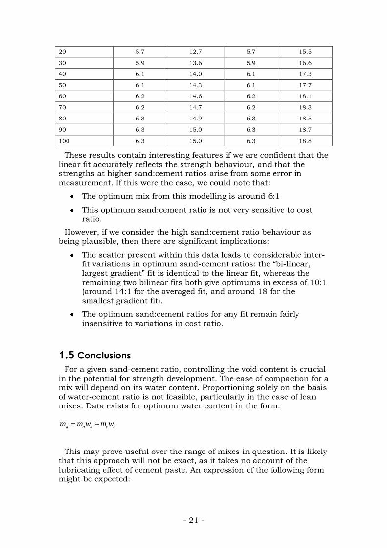
20 5.7 12.7 5.7 15.5
30 5.9 13.6 5.9 16.6
40 6.1 14.0 6.1 17.3
50 6.1 14.3 6.1 17.7
60 6.2 14.6 6.2 18.1
70 6.2 14.7 6.2 18.3
80 6.3 14.9 6.3 18.5
90 6.3 15.0 6.3 18.7
100 6.3 15.0 6.3 18.8
These results contain interesting features if we are confident that the linear fit accurately reflects the strength behaviour, and that the
strengths at higher sand:cement ratios arise from some error in measurement. If this were the case, we could note that:
The optimum mix from this modelling is around 6:1
This optimum sand:cement ratio is not very sensitive to cost
ratio.
However, if we consider the high sand:cement ratio behaviour as
being plausible, then there are significant implications:
The scatter present within this data leads to considerable inter-
fit variations in optimum sand-cement ratios: the “bi-linear, largest gradient” fit is identical to the linear fit, whereas the remaining two bilinear fits both give optimums in excess of 10:1
(around 14:1 for the averaged fit, and around 18 for the smallest gradient fit).
The optimum sand:cement ratios for any fit remain fairly
insensitive to variations in cost ratio.
1.5 Conclusions
For a given sand-cement ratio, controlling the void content is crucial in the potential for strength development. The ease of compaction for a
mix will depend on its water content. Proportioning solely on the basis of water-cement ratio is not feasible, particularly in the case of lean mixes. Data exists for optimum water content in the form:
w a a c cm m w m w
This may prove useful over the range of mixes in question. It is likely that this approach will not be exact, as it takes no account of the
lubricating effect of cement paste. An expression of the following form might be expected:

- 22 -
cw s s c c s
s
mm m w m w m f
m
Equation 1.21
Where the 3 terms on the right hand side represent coating the aggregate, hydrating the cement, and a cement lubrication effect for good compaction respectively.
Compaction of the mortar can be achieved using hand application or, more effectively, by mechanised techniques. Some data is available
on parameter ranges to use, though this is not conclusive or comprehensive.
As failure of mortar occurs by crack propagation, controlling pre-
stress cracking is important.
It can be seen that there is a considerable amount of data available. However, between the information available and simple rules of thumb
and recommendations, there is still quite a distance.
From the simple modelling conducted optimum values for
sand:cement ratio have been calculated using experimental data. However, the variability of some of this data leads to different fits giving greatly differing ratios (ranging from around 6:1 to around
18:1). This suggests further experimental work to:
Validate the methods proposed for calculating optimum water
content.
Resolve the break-point issue and hence allow more accurate
calculation of an optimum sand:cement ratio.

- 23 -
1.6 Reference List
Appa Rao, G. (2001) "Generalization of Abram's law for cement mortars", Cement and Concrete Research, 31 495-502.
Chandler, H. W., & Macphee, D. E. (2003) "A model for the flow of cement pastes", Cement and Concrete Research, 33 265-270.
Hausmann, M. R. (1990) Engineering Principles of Ground Modification, McGraw-Hill
New York.
Hotta, H., & Takiguchi, K. (1995) "Influence of drying and water supplying after drying on tensile strength of cement mortar", Nuclear Engineering and Design, 156
219-228.
Kerali, A. G., & Thomas, T. H. (2002) "Effect of mix retention and curing on low-cement walling blocks", Building Research & Information, 30(5), 1-5.
Kim, J.-K., Han, S. H., & Song, Y. C. (2002) "Effect of temperature and aging on the mechanical properties of concrete Part 1: Experimental results", Cement and Concrete Research, 32 1087-1094.
Kokobu, K., Cabrera, J. G., & Ueno, A. (1996) "Compaction properties of roller compacted concrete", Cement and Concrete Composites, 18 109-117.
. (1982). F. D. Lydon, Concrete Mix Design. London: Applied Science Publishers.
Neville, A. M. (1995) Properties of Concrete, Longman.
Orowan, E. (1948) "Fracture and strength of solids", Reports on Progress in Physics,
12 185-232.
Parsons, A. W. (1992) Compaction of soils and granular materials: A review of research performed at the Transport Research Laboratory, HMSO.
Popovics, Sandor (1998) Strength and related properties of concrete: A quantitative approach, John Wiley & Sons.
Sharma, P. C. (1983) "A mechanized process for producing ferrocement roof and wall elements", Journal of Ferrocement, 13(1), 13-260.
. (1983). G. H. Tattersall, & P. F. G. Banfill, The rheology of fresh concrete. London:
Pitman.
Thanh, N. H. (1991) "Optimal concrete composition based on paste content for ferrocement", Journal of Ferrocement, 21(4), 331-350.
Walkus, B. R. (1981). An efficient and economical system for producing ferrocement
elements. Vol. 11(2), 155-162.
Whittmann, F. E. (1983). Fracture Mechanics of Concrete. Phenomenological aspects of the fracture of concreteElsevier.

- 24 -
Appendix 1 : Modifications to
strength modelling
1.6.1 Modifications to thickness term
Actually, the sand will have a voids ratio:
s
vol voidsr
vol voids vol sand
Equation 1.22
For a given quantity of sand, there will be a voids volume of:
1
ss
s s
mv
r
Equation 1.23
This volume will be filled, or partially filled, by the mix of cement and
water present in the initial mix. If this water-cement mix is not large enough, then the volume of the mortar will be determined by the sand volume (case (i)). If the water cement mix is sufficiently voluminous,
the mix volume will be determined by the mass quantities (case(ii)).
For case (i), the determining criteria will be:
vol cement vol water vol voids in sand
1
c s cc cs
c w s s
m w wm mv
v
Equation 1.24
This simplifies to:
1
1
s c
s
c w s s
w wv
v
Equation 1.25
1
s w c s c s
c w s
w w v
v
Equation 1.26
If we are not interested in the case where paste content is less than voids volume, for strength reasons, then it is reasonable to take case
(ii) as the working situation:
s c w
s c w
m m mt
Equation 1.27
However, the quantity of water present is determined by the sand
and cement components, from:

- 25 -
w s s c cm m w m w Equation 1.28
In this case we may say that s c s s c c
s c w
m m m w m wt , and then
simplify to give:
1 c sc
s c w
w wt m
Equation 1.29
Giving an alternative value of mortar cost as:
1
1
c
m
s c
c s w
kcC
w wg
Equation 1.30
1.6.2 Labour Content
There should be some form of labour component in the production
costs for the mortar. A basic approximation would have labour cost as proportional to the volume of material being used:
1 s cl l c
c S w
w wC c m
Equation 1.31
Where Cl is the cost of labour, cl is the unit cost of labour (per unit
volume), and the other quantities are as before.
In this case we now have:
1 s cm c c s l
c S w
w wC Q c c c
Equation 1.32
Again, it should be possible to optimise for mortar cost with respect
to sand-cement ratio ( ), providing other values are known.
The labour costs may prove significant, and would be expected to
reduce the optimum sand-cement ratio, as previously there was no labour cost to increasing the total volume of mortar being used.
1
1
s cc s l
c S w
m
s c
c s w
w wk c c c
Cw w
g
Equation 1.33