morth section 900
DESCRIPTION
Morth 5th section 900TRANSCRIPT
784
SECTION 900 – MATERIALS DETAILS
SECTION 901 – PCC MATERIALS 901.01 Hydraulic Cement (a) General At the time cement is incorporated into the work, it shall meet the quality requirements of these specifications. Cement which has been in storage may be tested prior to use, and if tests show that it does not meet the requirements specified, it will be rejected. 10 A means for storing and protecting the cement against dampness shall be provided. Cement which has become partially set or which contains lumps or caked cement will be rejected. Cement salvaged from discarded or used sacks shall not be used. Different kinds or brands of cement, or cement of the same brand from different mills, even if tested and approved, shall not be mixed during use unless permitted, and then only as directed. They shall not be used alternately in any 1 pour for any structure, unless otherwise permitted. 20 (b) Portland Cement Portland cement shall conform to the requirements of the following cited specifications except as noted. 1. Requirements Cement Specifications Air-Entraining Portland Blast-Furnace 30 Slag Cement ................................................. AASHTO M 240, Type ISA Air-Entraining Portland Cement ................. AASHTO M 85, Type IA or IIIA Air-Entraining Portland-Pozzolan Cement ....................................................... AASHTO M 240, Type IP-A Portland Blast-Furnace Slag Cement .................... AASHTO M 240, Type IS Portland Cement ......................................... AASHTO M 85, Type I, II, or III Portland-Pozzolan Cement ................................... AASHTO M 240, Type IP Slag Modified Portland Cement, Type ISM ........................ AASHTO M 240 The exceptions to AASHTO M 240 are as follows: 40 a. The amount of pozzolan shall be limited to 20% ± 5% by
weight of the portland-pozzolan cement for the types IP and IP-A.
901.01
785
b. The pozzolan in the portland-pozzolan cements, types IP and
IP-A, shall be in accordance with ASTM C 618, class C or class F with the loss on ignition of the pozzolan limited to a maximum of 3%.
50 c. The pozzolan in the portland-pozzolan cements, types IP and
IP-A, shall be interground with the portland cement clinker. 2. Acceptance Criteria Portland cements and blended cements will be accepted based upon the manufacturer’s or manufacturer/distributor’s documented ability to consistently furnish these materials in accordance with the applicable AASHTO requirements. a. General Requirements Cements shall comply with the applicable requirements of 901 and will be 60 accepted by certification from qualified manufacturers or manufacturer/distributor. The manufacturer is defined as the plant producing the cement. A manufacturer or manufacturer/distributor shall become qualified by establishing a history of satisfactory quality control of cement produced as evidenced by results of tests performed by a testing laboratory which is regularly inspected by the Cement and Concrete Reference Laboratory of the National Institute of Standards and Technology. Proof of such inspection shall be furnished upon request. All certifications shall be prepared by the manufacturer or distributor in accordance with the applicable requirements of 916. If a manufacturer or distributor elects to supply portland cement with a higher sulfur trioxide content in accordance with footnote B 70 from Table 1 in AASHTO M 85, it shall supply all of the required supporting data to the Office of Materials Management prior to supplying such cement. A list of Qualified Manufacturers and Manufacturer/Distributors will be maintained by the Department. The manufacturer or manufacturer/distributor shall conduct sufficient tests to ensure that adequate quality control is maintained and that cement furnished is in accordance with the specification requirements. Documentation pertaining to cement shipped on certification shall be maintained for a period of at least 3 years and shall be provided when requested. 80 Random samples of cement will be obtained at the concrete plant. If the sample is not in accordance with the specification requirements, an investigation will be conducted. A copy of the findings and conclusions resulting from the investigation will be furnished to the Contractor. Unless the investigation finds the Department is responsible for the failure to comply, the cost of the investigation plus any required corrective action will be assessed to the Contractor.
901.01
786
b. Requirements for Domestic Source Qualification Cement manufacturers requesting to be qualified to supply cement shall provide 90 the following: (1) For the initial qualification, the manufacturer shall provide
to the Office of Materials Management a QCP in accordance with the applicable requirements of ITM 806. The QCP shall also include the location and type of samples taken, and a monthly summary of mill test data for the previous years production. A current Material Safety Data Sheet shall be submitted as an integral part of the initial qualification package. 100
(2) To maintain qualification, a monthly average of mill test
data shall be submitted to the Office of Materials Management. If a specific type of cement is not manufactured in a given month, the monthly submittal shall state “No type ______ cement was manufactured during the month of __________ 20____”.
c. Requirements for Foreign Source Qualification Foreign cement manufacturers or their domestic distributors requesting to be 110 qualified to supply cement shall provide the following: (1) For the initial qualifications, the manufacturer and
distributor shall provide to the Office of Materials Management a QCP in accordance with the applicable requirements of ITM 806. The QCP shall also include the location and type of samples taken, and a summary of complete test results from the proposed cement source. A current Material Safety Data Sheet shall be submitted as an integral part of the initial qualification package. The QCP 120 must explain the linkage between the cement being furnished and the manufacturer’s/distributor’s quality control data, relative to ship-loads, barge-loads, railroad car-loads, etc.
(2) Once the initial qualifications have been met, the
manufacturer or distributor shall be required to furnish the cement test results for each shipment prior to Department cement usage for the first 5 cement shipments, which are intended for Department use. The test results for all 5 of 130 these cement shipments must fully comply with the required material specifications. If not, this requirement will be continued for subsequent cement shipments until 5 consecutive cement shipment test results fully comply with
901.01
787
the required material specifications, or Department source approval is withdrawn due to the inability to consistently supply satisfactory cement.
(3) To maintain qualification after compliance with the
previous requirements, a monthly submission of all cement 140 shipment test results for cement which is intended for Department usage shall be submitted to the Office of Materials Management. If no cement shipments are received during a given month, the monthly submittal shall state “No cement was received during the month of __________, 20____”.
d. Certification Only qualified manufacturers and manufacturer/distributors as identified by the Department’s list of Qualified Manufacturers and Manufacturer/Distributors may 150 furnish cement on certification. A sample certification form addressing all of the required information is included in ITM 804. Alternate procedures and forms will be considered when requested, and will be approved if there is a positive link between the cement furnished and the manufacturer’s quality control data. (c) Masonry Cement Masonry cement shall be in accordance with ASTM C 91, except the air content test and the water retention test may be waived. 160 901.02 Fly Ash Used as a Pozzolan (a) General Fly ash is the finely divided residue that results from the combustion of ground or powered coal. In general, class F fly ash is produced from burning anthracite or bituminous coal and class C fly ash is produced from burning lignite or subbituminous coal. Fly ash will be accepted from 1 of the sources on the Department’s list of 170 approved Fly Ash and Ground Granulated Blast Furnace Slag Sources. Fly ash from different sources or different types of fly ash shall not be mixed or used alternately in the same construction unless authorized in writing. Fly ash will be subject to random assurance sampling and testing by the Department. Failure of these random samples to meet the specified requirements will be cause for suspension of the fly ash source approval. (b) Acceptance Criteria Acceptance is based upon the supplier’s documented ability to consistently furnish material in accordance with the specified requirements. 180
901.02
788
1. Requirements The fly ash shall be in accordance with AASHTO M 295 for class C or class F, with the following exceptions: Loss on Ignition (LOI), Maximum % ............................................................ 3 Autoclave Expansion or Contraction, Maximum % ................................... 0.5 Fineness: Amount retained when wet-sieved on No. 325 (45 µm) sieve, Maximum % ................................................................. 30 190 On days when fly ash is being accumulated for use as a pozzolan, the supplier shall obtain a minimum of 1 sample per day and furnish test results for moisture content, loss on ignition, and No. 325 (45 µm) sieve residue for each sample. For each 2,000 t (1,800 Mg) produced, a complete AASHTO M 295 analysis shall be performed on a sample composited randomly from the daily samples. The method of randomization shall be subject to approval by the Department. 2. Test and Calibration Procedure The testing procedures followed shall be in accordance with ASTM C 311 or 200 other methods approved in writing by the Department. The minimum frequency for calibration of test equipment is: a. The No. 325 (45 µm) sieve shall be calibrated every 100
determinations or every 6 months, whichever comes first. b. The muffle furnace used for LOI determinations shall have a
newly installed thermocouple every 6 months. 210 c. The analytical balances and scales shall be calibrated each year. d. The concrete compression machine shall be calibrated
annually. e. The Blaine apparatus shall be calibrated annually. f. All instrumentation used for rapid chemical analysis shall
comply with applicable requirements of ASTM C 114 using NIST Fly Ash reference materials. 220
3. Documentation Fly ash suppliers requesting approval shall supply the following: a. For the initial approval, a current Materials Safety Data Sheet
and a summary of results for all specified tests for 6
901.02
789
consecutive months shall be submitted. No test results shall be more than 1 year old at the time of request.
b. To maintain approval, a summary of results for all specified 230
tests shall be submitted monthly. The results of the daily tests shall be available by telephone during normal working hours.
c. The fly ash suppliers shall furnish a QCP in accordance with
the applicable requirements of ITM 806. The QCP shall ensure the Department of a continuous supply of fly ash complying with the requirements. This QCP will be reviewed to determine its adequacy.
d. Certification: 240 (1) For source approval, the supplier shall furnish a
certification indicating the class of fly ash, the name, location, and unit of the generating plant. It shall state that all fly ash shipped for use on Department projects will be produced under appropriate quality control and shall be in accordance with the specified requirements. It shall further indicate that the power company will participate in appropriate inspection and assurance testing. A sample certification form is set out in ITM 804. 250
(2) For certification of test reports, the test results generated in
accordance with 901.02(b)1 shall be summarized and submitted monthly. The reports shall state the name and location of the testing facility, and shall be signed by the chemist or technical manager. This certification shall also identify the concrete plants receiving fly ash represented by these results.
901.03 Ground Granulated Blast Furnace Slag Used As a Pozzolan 260 (a) General Blast furnace slag shall consist of the non-metallic product, consisting essentially of silicates and aluminosilicates of calcium and other bases, that is developed in a molten condition simultaneously with iron in a blast furnace. A glassy granular material is formed when molten blast furnace slag is rapidly chilled by immersion in water. This material is then ground to cement fineness, producing ground granulated blast furnace slag. Ground granulated blast furnace slag will be accepted from 1 of the sources on 270 the Department’s list of approved Fly Ash and Ground Granulated Blast Furnace Slag Sources. Ground granulated blast furnace slag from different sources or
901.03
790
different grades of ground granulated blast furnace slag shall not be mixed or used alternately in the same construction unless approved in writing. Ground granulated blast furnace slag will be subject to random assurance sampling and testing by the Department. Failure of these random samples to be in accordance with the specified requirements will be cause for suspension of ground granulated blast furnace slag source approval. (b) Acceptance Criteria 280 Ground granulated blast furnace slag will be accepted based on the manufacturer’s or manufacturer/distributor’s documented ability to consistently furnish these materials in accordance with the applicable ASTM and AASHTO requirements. 1. Requirements The ground granulated blast furnace slag shall be in accordance with ASTM C 989 for grade 100 or 120. For each 2,000 t (1,800 Mg) produced, a complete ASTM C 989 analysis shall 290 be performed on a sample composited randomly from the daily samples. The method of randomization shall be subject to approval by the Department. 2. Test and Calibration Procedure The testing procedures followed shall be in accordance with ASTM C 989 or other methods approved in writing by the Department. The minimum frequency for calibration of test equipment is: a. The No. 325 (45 µm) sieve shall be calibrated every 100 300
determinations or every 6 months, whichever comes first. b. The analytical balances and scales shall be calibrated each year. c. The concrete compression machine shall be calibrated
annually. d. The Blaine apparatus shall be calibrated annually. e. All instrumentation used for rapid chemical analysis shall be in 310
accordance with the applicable requirements of ASTM C 114 using NIST reference materials.
3. Documentation Ground granulated blast furnace slag suppliers requesting approval shall supply the following:
901.03
791
a. For the initial approval, a current Materials Safety Data Sheet and a summary of results for all specified tests for 6 consecutive months shall be submitted. No test results shall be 320 more than 1 year old at the time of request.
b. To maintain approval, a summary of results for all specified
tests shall be submitted monthly. The results of the daily tests shall be available by telephone during normal working hours.
c. The ground granulated blast furnace slag suppliers shall furnish
a QCP in accordance with the applicable requirements of ITM 806. The QCP shall ensure the Department of a continuous supply of ground granulated blast furnace slag 330 which is in accordance with the requirements. This QCP will be reviewed to determine its adequacy.
d. Certification: (1) For source approval, the supplier shall furnish a
certification indicating the grade of ground granulated blast furnace slag, the name, location, and type of manufacturing facility. It shall state that the ground granulated blast furnace slag shipped for use on 340 Department projects will be produced under appropriate quality control and shall be in accordance with the specified requirements. A sample certification form addressing all of the required information is included in ITM 804.
(2) For certification of test reports, the test results generated in
accordance with 901.03(b) shall be summarized and submitted monthly. The reports shall state the name and location of the testing facility, and shall be signed by the 350 chemist or technical manager. This certification shall also identify the concrete plants receiving ground granulated blast furnace slag represented by these results.
901.04 Silica Fume Used As a Pozzolanic Mineral Admixture (a) General Silica fume will be accepted from 1 of the suppliers on the Department’s list of approved Pozzolanic Suppliers. Silica fume from more than 1 of these suppliers shall not be mixed or used alternatively in the same construction unless authorized in 360 writing. Silica fume will be subject to random assurance sampling and testing by the Department. Failure of the random samples to meet the specified requirements will be cause for suspension of the silica fume supplier’s approval.
901.04
792
(b) Acceptance Criteria Acceptance of silica fume will be based on the manufacturer’s documented ability to consistently furnish material in accordance with the specified requirements. 1. Requirements The silica fume shall be in accordance with AASHTO M 307 with the following 370 exceptions: a. Reactivity with cement alkalies shall not be required. b. The oversize, amount retained on the No 325 (45 µm) sieve, in
accordance with ASTM C 1240, shall be conducted. c. The oversize, amount retained on the No. 325 (45 µm) sieve,
shall not be more than 10%. 380 d. Accelerated pozzolanic activity index, in accordance with
ASTM C 1240, shall be conducted in lieu of strength activity index.
e. The accelerated pozzolanic activity index shall be a minimum
of 85% at 7 days. f. The increase of drying shrinkage of mortar bars at 28 days shall
be conducted in accordance with ASTM C 1240. 390 g. The increase of drying shrinkage of mortar bars at 28 days shall
be not more than 0.10%. 2. Frequency of Testing a. The manufacturer shall obtain a minimum of 1 sample for each
400 t (400 Mg) of material produced. Test results for moisture content, and loss on ignition, shall be furnished for each sample.
400 b. For each 2,000 t (2,000 Mg) produced, a complete AASHTO
M 307 analysis shall be performed on a sample composed randomly from daily samples. The method of randomization shall be subject to approval by the Department. The optional chemical requirements identified in AASHTO M 307 shall be reported in addition to the increase of drying shrinkage of mortar bars as well as the standard chemical and physical requirements.
901.04
793
3. Test and Calibration Procedure 410 The minimum frequencies for calibration of test equipment shall be as follows: a. The analytical balances and scales shall be calibrated annually. b. The concrete compression machine shall be calibrated
annually. c. The Blaine apparatus shall be calibrated annually. d. All instrumentation used for rapid chemical analysis shall be in 420
accordance with AASHTO T 105. 4. Documentation Silica fume suppliers requesting approval shall supply the following to the Office of Materials Management: a. For initial approval, a current Material Safety Data Sheet and a
summary of results for all specified tests for 6 consecutive months shall be submitted. No test results shall be more than 1 year old at the time of the request. 430
b. To maintain approval, a summary of results for all specified
tests shall be submitted monthly. c. A QCP in accordance with the applicable requirements of ITM
806 shall be submitted. The QCP shall ensure the Department a continuous supply of silica fume complying with the material requirements and calibration procedures. This QCP will be reviewed by the Office of Materials Management to determine its adequacy. 440
d. Certification: (1) For approval, the supplier shall furnish a certification
indicating the name, location, and type of manufacturing facility, which includes the metallurgical process and furnace. It shall state that the silica fume shipped for use on Department projects will be produced under appropriate quality control and shall be in accordance with the specified requirements. A sample certification is set out in 450 ITM 804.
(2) For certification of test reports, the results generated in
accordance with 901.04(b) shall be summarized and submitted monthly. The reports shall state the name and
901.04
794
location of the testing facility, and shall be signed by the chemist or technical manager. This certification shall also identify the concrete plants receiving silica fume represented by these results.
460 901.05 Chemical Anchor System Chemical anchor systems shall be furnished from the Department’s list of approved Chemical Anchor Systems. Chemical anchor systems may be added to the approved list by completing the requirements of ITM 806, Procedure F and passing required laboratory testing. (a) Requirements Chemical anchor systems shall be in accordance with the following: 1. Chemical anchor systems shall be 2 part systems which are capable 470
of anchoring deformed steel reinforcing bars and grouting load transfer dowels.
2. Chemically anchored steel reinforcing bars shall be capable of
withstanding a tensile load equal to the yield strength of a #7 (#22), grade 60 (400), epoxy coated, deformed steel reinforcing bar.
3. Chemical anchor systems shall be capable of filling the entire
annular space between the concrete and the steel reinforcing bar or 480 dowel and remain in place until the chemical anchor is completely cured.
(b) Laboratory Testing The Department will test chemical anchor systems in accordance with ITM 807. 901.06 PCC Sealer/Healers PCC sealer/healers shall be furnished from the Department’s list of approved PCC Sealer/Healers. PCC sealer/healers may be added to the approved list by completing the requirements in ITM 806, Procedure F and passing required 490 laboratory testing. (a) Requirements PCC sealer/healers shall be in accordance with the following: 1. PCC sealer/healers shall be 2 part systems, capable of sealing and
healing cracks in PC pavement. 2. PCC sealer/healers shall be capable of restoring the original
integrity of a PCC beam broken in flexure. 500
901.05
795
3. All 4 beams used for testing sealer/healers shall break at a location different from the original break or with a flexural strength greater than or equal to 550 psi (3,800 kPa).
4. The viscosity of PCC sealer/healers shall be sufficient to penetrate
a crack 1/32 in. (0.8 mm) wide and 6 in. (150 mm) in depth. (b) Laboratory Testing The Department will test PCC sealer/healers in accordance with ITM 808. 510 901.07 Rapid Setting Patch Materials Rapid setting patch materials shall be selected from the Department’s list of approved Rapid Setting Patch Materials. A rapid setting patch material may be added to the approved list by completing the requirements in ITM 806, Procedure F. (a) Normal Weather Mixes Normal weather rapid setting patch materials shall be used for ambient temperatures of 32 - 85°F (0 - 30°C). 520 (b) Hot Weather Mixes Hot weather rapid setting patch materials shall be used for ambient temperatures above 85°F (30°C). (c) Requirements Rapid setting patch materials shall be capable of being utilized in patches ranging from 1 in. (25 mm) to full depth without bonding agents, no curing material shall be required, and shall be capable of being surface sealed with an epoxy sealer. These products shall not contain soluble chlorides as an ingredient of 530 manufacture nor shall they require chemical additives. The color shall be similar to PCC. They shall be single packaged dry mix requiring only water just prior to mixing. They shall be packaged in 40 to 60 lb (18 to 27 kg) bags with a neat yield of approximately 0.40 cu yd (0.011 m3) and shall allow at least a 50% extension, by weight (mass) with a 3/8 in. (10 mm) or a 1/2 in. (13 mm) round aggregate. The minimum shelf life shall be 12 months. Mixing shall be conducted with small concrete mixers or with a drill or paddle 540 mixer and shall be suitable for finishing with hand tools. Rapid setting patch materials shall be in accordance with ASTM C 928 with the following exceptions.
901.07
796
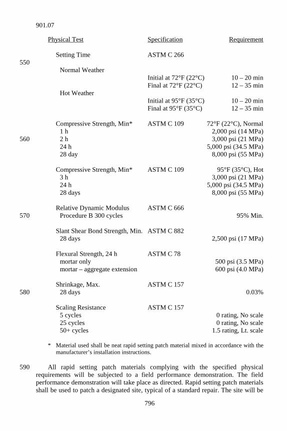
Physical Test Specification Requirement Setting Time ASTM C 266 550 Normal Weather Initial at 72°F (22°C) 10 – 20 min Final at 72°F (22°C) 12 – 35 min Hot Weather Initial at 95°F (35°C) 10 – 20 min Final at 95°F (35°C) 12 – 35 min Compressive Strength, Min* ASTM C 109 72°F (22°C), Normal 1 h 2,000 psi (14 MPa) 2 h 3,000 psi (21 MPa) 560 24 h 5,000 psi (34.5 MPa) 28 day 8,000 psi (55 MPa) Compressive Strength, Min* ASTM C 109 95°F (35°C), Hot 3 h 3,000 psi (21 MPa) 24 h 5,000 psi (34.5 MPa) 28 days 8,000 psi (55 MPa) Relative Dynamic Modulus ASTM C 666 Procedure B 300 cycles 95% Min. 570 Slant Shear Bond Strength, Min. ASTM C 882 28 days 2,500 psi (17 MPa) Flexural Strength, 24 h ASTM C 78 mortar only 500 psi (3.5 MPa) mortar – aggregate extension 600 psi (4.0 MPa) Shrinkage, Max. ASTM C 157 28 days 0.03% 580 Scaling Resistance ASTM C 157 5 cycles 0 rating, No scale 25 cycles 0 rating, No scale 50+ cycles 1.5 rating, Lt. scale * Material used shall be neat rapid setting patch material mixed in accordance with the
manufacturer’s installation instructions. All rapid setting patch materials complying with the specified physical 590 requirements will be subjected to a field performance demonstration. The field performance demonstration will take place as directed. Rapid setting patch materials shall be used to patch a designated site, typical of a standard repair. The site will be
901.07

797
evaluated after 1 year’s exposure. Approval will be based on visible signs of distress, such as cracking, crazing, scaling, spalling, wearing, edge fraying, corner cracking, or debonding. (d) Test Report Testing shall be performed by a recognized laboratory in accordance with ITM 806. Test reports shall not be more than 5 years old on January 1st of the 600 approval year. 901.08 Packaged, Dry, Combined Materials for Mortar and Concrete These materials shall be in accordance with ASTM C 387. All packages shall be identified as conforming to ASTM C 387. The markings shall also show the kind and type of material, the net weight in each bag, the yield in cubic feet (cubic meters) or yield in square feet per inch (square meters per millimeter) of thickness, and the amount of water recommended for mixing to produce a 2 in. to 3 in. (50 mm to 75 mm) slump. 610 901.09 Air-Cooled Blast Furnace Slag for Retaining Walls If ACBF or coarse aggregate is used, and soil, B borrow, structural backfill, or coarse aggregate is to be placed above the ACBF or coarse aggregate, a single layer of geotextile shall be placed on top of the ACBF or coarse aggregate in accordance with 616.11. A type C certification in accordance with 916 for the geotextile materials shall be furnished to the Engineer prior to use. ACBF shall be in accordance with the pH, chlorides, sulfates, organic content, resistivity, and permeability requirements of structure backfill as listed in 211.07. It shall also be in accordance with ITM 212. Total sulfides shall also be determined in 620 accordance with EPA 376.1, using the 100-mL pH water samples obtained during the ITM 212 test, and shall not exceed 400 ppm. The ACBF shall have a maximum corrosion rate as follows if tested in accordance with ASTM G 59. (a) Zinc corrosion rate, first 2 years ..................................... 15 µm/yr/side (b) Zinc corrosion rate, to depletion ....................................... 4 µm/yr/side (c) Carbon-steel corrosion rate ............................................. 12 µm/yr/side 901.10 Components of MSE Retaining Walls 630 (a) PCC Components 1. Face Panels Precast concrete face panels shall be produced from a source listed in the Department’s List of Certified Precast Concrete Producers, in accordance with ITM 813. Concrete shall have a compressive strength equal to or greater than 4,000 psi (27.5 MPa) at 28 days.
901.10
798
The target water/cementitious ratio for the concrete mix design shall not exceed 0.435. The cement content and target water/cementitious ratio of the concrete mix 640 design shall be sufficient to obtain the specified minimum 28-day compressive strength. Approved air entraining admixture and chemical admixture Type A, B, C, D, or E may be used. Ground-reinforcement connection hardware and reinforcing bar lifting devices shall be set in place and secured prior to beginning casting, in accordance with the dimensions and tolerances shown on the working drawings. a. Production Control Testing and Inspection The manufacturer shall provide for all testing and inspection services during 650 each day’s production of the panels. The frequency of production control testing shall be based on a lot of 50 panels, or fraction thereof, for each day’s production. Sampling and testing of the plastic concrete shall be in accordance with 505.01, or the ASTM equivalent. A minimum of 1 water/cementitious ratio, and slump, air content, and relative yield tests shall be run per production lot, per day. A minimum of two 6 in. by 12 in. (150 mm by 300 mm) cylinders shall be cast per day’s production lot for compressive strength determination. Cylinders shall be cured in the same manner as the panels they represent. Relative yield, air content, and slump of the concrete shall be in accordance with 702.05. Compressive strength shall be determined in accordance with AASHTO T 22 or ASTM C 39, with lot acceptance 660 based on the average of 2 cylinders tested at an age no greater than 28 days. Panels shall not be shipped until the compressive strength meets or exceeds the 28 day requirement. If the cylinder-test results do not satisfy the requirements described herein, and additional cylinders for testing are not available, the manufacturer may core the panels. The wall manufacturer shall randomly select 2 panels from the lot for coring in accordance with AASHTO T 24 or ASTM C 42. The wall manufacturer shall obtain 1 core on the backside of each panel with a device that produces uniform test samples without coring completely through the panel. Coring shall not be located 670 within 6 in. (150 mm) of the panel fasteners or the edges of the panels, and shall avoid the panel's reinforcing steel. The wall manufacturer shall fill the core holes with equivalent concrete materials or rapid setting patch materials, and trowel to produce a smooth finish. Excess material removed during troweling shall not be reused. If rapid setting patch material is used, mixing and curing shall be in accordance with the manufacturer's recommendations. Compressive strength testing shall be performed on the cores. If the average strength-test results from the cores satisfy or exceed the requirements described herein, the production lot panels may be shipped. 680 b. Casting The panels shall be cast on a flat area, with the front face of the form at the bottom, and the back face at the upper part. Tie strip guides shall be set on the rear face. The concrete in each unit shall be placed without interruption and shall be
901.10
799
consolidated as necessary to prevent the formation of segregation or cleavage planes. Clear form oil from 1 manufacturer shall be used throughout the casting operation. c. Curing The panels shall be cured for a sufficient length of time such that the concrete develops the specified compressive strength. 690 d. Removal of Forms The forms shall remain in place until they can be removed without damage to the unit. e. Concrete Finish The concrete surface for the front panel face shall have a surface finish produced from contact with the form. The rear face of the panel shall be screeded to eliminate open pockets of aggregate and surface distortions in excess of 1/4 in. (6 mm). 700 f. Tolerances All panels shall be manufactured within the tolerances as follows: (1) Panel Dimensions Lateral position of tie strips shall be within 1 in. (25 mm). All other dimensions shall be within 3/16 in. (5 mm). (2) Panel Squareness Squareness, as determined by the difference between the 2 diagonals, shall not exceed 1/2 in. (13 mm). 710 (3) Panel-Surface Finish Surface defects on smooth formed surfaces measured on a length of 5 ft (1.5 m) shall not exceed 1/8 in. (3 mm). Surface defects on textured finished surfaces measured on a length of 5 ft (1.5 m) shall not exceed 5/16 in. (5 mm). g. Compressive Strength Verification Verification of the panels’ compressive strengths will be conducted by the Engineer. The frequency of verification testing will be 1 test for every 750 panels per manufacturer with a minimum of 1 test per contract. One panel will be randomly 720 selected and 2 locations will be selected for coring. The Contractor shall obtain two 4 in. (100 mm) cores on the backside of the panel without coring completely through the panel, in the presence of the Engineer. The Contractor shall refill the core holes with rapid setting patch materials and trowel to produce a smooth finish. Excess material removed during troweling shall not be reused. Mixing and curing of the patching materials shall be in accordance with the manufacturer’s recommendations. The Engineer will test the cores in accordance with AASHTO T 24. The verification test results will be averaged and shall be in accordance with 901.10(a)1a. If the initial verification test results do not satisfy the requirements described herein, 730
901.10
800
the Engineer will randomly select 2 different panels for additional verification testing. If the additional verification tests satisfy the requirements described herein, no further action is required. If the test results still do not satisfy the requirements described herein, installation of panels shall cease and the Engineer will conduct an investigation. Panels manufactured on the same dates as the panels cored for verification tests that have already been installed will be considered and adjudicated as a failed material in accordance with 105.03. The Engineer will conduct verification testing until 3 consecutive dates of production satisfy the strength requirements described herein. The Contractor or wall manufacturer shall make arrangements so that panels from 3 consecutive dates of production are accessible for 740 coring. Installation of panels may resume once acceptable verification testing results are achieved. h. Rejection Units shall be subject to rejection due to their failure to be in accordance with the requirements specified above. The following defects may result in rejection: (1) Defects which indicate imperfect molding. (2) Defects which indicate honeycombed or open texture 750
concrete. (3) Defects in the physical characteristics of the concrete, such
as broken or chipped concrete, or color variations or dunnage marks on the front face due to excessive form oil or other reasons.
The Engineer will determine whether spalled, honeycombed, chipped, or otherwise defective concrete shall be repaired or be cause for rejection. Repair of concrete, if permitted, shall be completed in a manner which is acceptable to the 760 Engineer. Repair to concrete surfaces that are to be exposed to view after completion of construction shall be subject to approval. i. Marking The place and date of manufacture, and production lot number shall be shown on the rear face of each panel. j. Handling, Storage, and Shipping All panels shall be handled, stored, and shipped so as to eliminate the danger of chipping, cracks, fractures, or excessive bending stresses. Panels in storage shall be 770 supported on blocking located immediately adjacent to tie strips to avoid bending the tie strips. 2. Coping The coping may be precast or cast-in-place.
901.10
801
(b) Joint Spacers and Joint Covering The horizontal and vertical joint spacers shall include compression blocks, pins, or other manufacturer’s recommended materials to provide a uniform joint. 780 The joint cover shall be either a non-woven needle-punch polyester geotextile or a woven monofilament polypropylene. The joint cover shall be attached to the rear face of the panels with a manufacturer’s recommended adhesive. A letter certifying that the joint spacers and joint cover adhesive material supplied is in accordance with the manufacturer’s recommendations shall be provided prior to use of the materials.
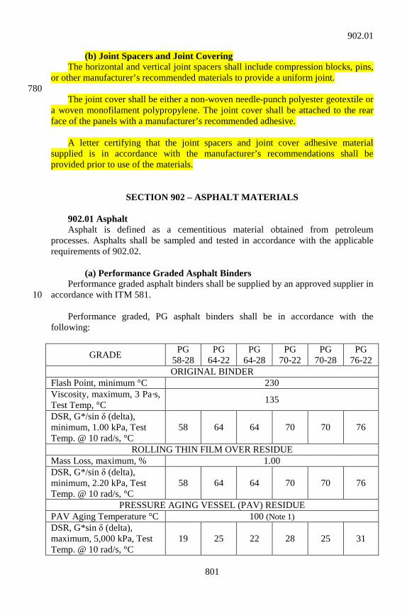
SECTION 902 – ASPHALT MATERIALS 902.01 Asphalt Asphalt is defined as a cementitious material obtained from petroleum processes. Asphalts shall be sampled and tested in accordance with the applicable requirements of 902.02. (a) Performance Graded Asphalt Binders Performance graded asphalt binders shall be supplied by an approved supplier in accordance with ITM 581. 10 Performance graded, PG asphalt binders shall be in accordance with the following:
GRADE PG 58-28
PG 64-22
PG 64-28
PG 70-22
PG 70-28
PG 76-22
ORIGINAL BINDER Flash Point, minimum °C 230 Viscosity, maximum, 3 Pa·s, Test Temp, °C 135
DSR, G*/sin δ (delta), minimum, 1.00 kPa, Test Temp. @ 10 rad/s, °C
58 64 64 70 70 76
ROLLING THIN FILM OVER RESIDUE Mass Loss, maximum, % 1.00 DSR, G*/sin δ (delta), minimum, 2.20 kPa, Test Temp. @ 10 rad/s, °C
58 64 64 70 70 76
PRESSURE AGING VESSEL (PAV) RESIDUE PAV Aging Temperature °C 100 (Note 1) DSR, G*sin δ (delta), maximum, 5,000 kPa, Test Temp. @ 10 rad/s, °C
19 25 22 28 25 31
902.01

802
Physical Hardening Report (Note 2) Creep Stiffness, S, maximum, 300 MPa, m-value, minimum, 0.300 Test Temp. @ 60 s, °C
-18 -12 -18 -12 -18 -12
Notes: 1. Oven temperature tolerance shall be ± 0.5°C. 2. Physical Hardening is performed on a set of asphalt beams according to AASHTO
T 313, Section 12.1, except the conditioning time is extended to 24 h ± 10 min at 10°C above the minimum performance temperature. The 24 h stiffness and m-value are reported for information purposes only.
A PG 58-28 or PG 64-22 binder may be modified by in-line blending with styrene butadiene rubber, SBR, polymer latex at the HMA plant in accordance with ITM 581. A PG 58-28 may be modified to a PG 64-28 and a PG 64-22 may be modified to a PG 70-22. 20 The SBR polymer latex shall be in accordance with the following:
SBR POLYMER LATEX Total Polymer Solids, % by weight 60 – 72 Butadiene, % by weight, minimum 68 Residual Styrene, % by weight, maximum 0.1 Ash, % of total polymer solids by weight, maximum 3.5 pH 9 – 11 Viscosity, Brookfield model RVF, Spindle No. 2 @ 20 rpm @ 25oC, maximum 2,000
A type A certification for the SBR polymer latex shall be furnished in accordance with 916. The minimum SBR polymer latex content shall be 2.5 %. The SBR polymer latex content may be reduced below the minimum content provided, if the following requirements are met: 30 1. An AASHTO accredited laboratory shall blend the PG binder and
SBR polymer latex at the proposed SBR polymer latex content and test and grade the modified PG binder in accordance with AASHTO M 320.
2. The laboratory test results verifying the blend and compliance with
902.01(a) shall be submitted to the Engineer for approval. 3. The source of the PG Binder or SBR polymer latex shall not be
changed. 40
902.01
803
1. Lots and Sublots A binder lot for each grade of PG binder will be 1 week of HMA production. Lots will be further subdivided into sublots for each calendar day that HMA is produced. 2. Sampling An acceptance sample and backup sample shall be taken from the asphalt delivery system at the HMA plant. The 2 samples will represent a sublot. A copy of a load ticket identifying the binder source shall be submitted with the sublot samples. 50 The Engineer will take immediate possession of the samples. 3. PG Binder Testing The Department will randomly select 1 sublot from each lot in accordance with ITM 802 for either complete or partial testing in accordance with AASHTO M 320. Complete PG binder testing will consist of RTFO DSR and PAV BBR testing. Partial PG binder testing will consist of RTFO DSR testing. Rotational viscosity and flashpoint tests are not required. If the sublot selected is in accordance with the specifications, the lot will be accepted. If the selected sublot is not in accordance with the specifications, the material will be adjudicated as a failed material in 60 accordance with 105.03. 4. Appeals If the Contractor does not agree with the acceptance test results for the lot, a request may be made in writing for additional testing. The appeal shall be submitted within 15 calendar days of receipt of the Department’s written results. The basis of the appeal shall include complete AASHTO M 320 test results for the specific sublot in question. The appeal results will replace all previous test results for acceptance of the lot. 70 (b) Asphalt Emulsions Asphalt emulsions shall be composed of an intimate homogeneous suspension of a base asphalt, an emulsifying agent, and water. Asphalt emulsions may contain additives to improve handling and performance characteristics. Failure of an emulsion to perform satisfactorily in the field shall be cause for rejection, even though it passes laboratory tests. The grade used shall be in accordance with the table for asphalt emulsions as shown herein. AE-90 is a medium breaking, low-penetration, high-asphalt content type, intended for hot and cold plant mixing, road mixing, and seal coats or as otherwise 80 specified. AE-90S is a rapid setting, anionic type emulsion for seal coat applications. AE-150 is a medium breaking, moderately soft penetration type, intended for use in surface treating, tack coats, and coating open and dense graded aggregate, or as otherwise specified.
902.01
804
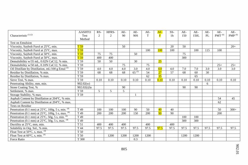
AE-150-L is a medium-breaking, relatively low-viscosity type. It may be specified in lieu of AE-T or AE-150 when a softer asphalt or greater aggregate 90 penetration is desired. AE-150-L is suitable for sand seals. AE-PL is a medium-slow-breaking, low-viscosity, low-asphalt content type, intended for use as a prime or as dust palative. AE-T is a medium-breaking, comparatively low penetration type, intended for tack coats, seed mulching, or as otherwise specified. HFRS-2 is a quick-breaking, high-viscosity, high-float, relatively high asphalt content type, intended for seal coats. 100 RS-2 is a quick-breaking, high-viscosity, relatively high-asphalt content type, intended for seal coats. AE-PMP is a polymerized modified asphalt emulsion intended for use as a prime coat material. AE-PMT is a polymerized modified asphalt emulsion intended for use as a tack coat material. 110 SS-1h is a slow setting, hard penetration type, intended for tack coats. AE-F is a medium setting, hard penetration, diluted emulsion intended for fog sealing. The requirements for asphalt emulsions shall be in accordance with the following:
902.01
805
Characteristic (1) (2) AASHTO
Test Method
RS- 2
HFRS- 2
AE- 90
AE- 90S
AE- T
AE- F
SS- 1h
AE- 150
AE- 150L
AE- PL
AE- PMT (6)
AE- PMP (6)
Test on Emulsion Viscosity, Saybolt Furol at 25°C, min. T 59 50 20 50 20+ Viscosity, Saybolt Furol at 25°C, max. T 59 100 100 100 100 115 100 Viscosity, Saybolt Furol at 50°C, min. T 59 75 75 50 75 Viscosity, Saybolt Furol at 50°C, max. T 59 400 400 300 Demulsibility w/35 mL, 0.02N CaC12, % min. T 59 50 50 30 25 Demulsibility w/50 mL, 0.10N CaC12, % min. T 59 75 75 25+ 25+ Oil Distillate by Distillation, mL/100 g Emul (3) T 59 4.0 4.0 4.0 3.0 4.0 4.0 4.0 7.0 7.0 3.0 3.0 3.0 Residue by Distillation, % min. T 59 68 68 68 65 (5) 54 27 57 68 60 30 Residue by Distillation, % max. T 59 62 35 65 Sieve Test, % max. T 59 0.10 0.10 0.10 0.10 0.10 0.10 0.10 0.10 0.10 0.10 0.10 0.10 Penetrating Ability, mm, min. 902.02(w) 6 Stone Coating Test, % 902.02(t)3a 90 90 90 Settlement, % max. T 59 5 5 5 Storage Stability, % max. T 59 1 Asphalt Content by Distillation at 204°C, % min. 54 45 Asphalt Content by Distillation at 204°C, % max. 62 Tests on Residue Penetration (0.1 mm) at 25°C, 100g, 5 s, min. (4) T 49 100 100 100 90 50 40 40 50 300+ Penetration (0.1 mm) at 25°C, 100g, 5 s, max. (4) T 49 200 200 200 150 200 90 90 200 Penetration (0.1 mm) at 25°C, 50g, 5 s, min. (4) T 49 100 100 Penetration (0.1 mm) at 25°C, 50g, 5 s, max. (4) T 49 300 300 Ductility at 25°C, mm, min. T 51 400 400 400 400 400 Solubility in Org. Sol., % min. T 44 97.5 97.5 97.5 97.5 97.5 97.5 97.5 97.5 97.5 97.5 97.5 97.5 Float Test at 50°C, s, max. (4) T 50 Float Test at 60°C, s, min. (4) T 50 1200 1200 1200 1200 1200 1200 Force Ratio T 300 0.3
902.01
806
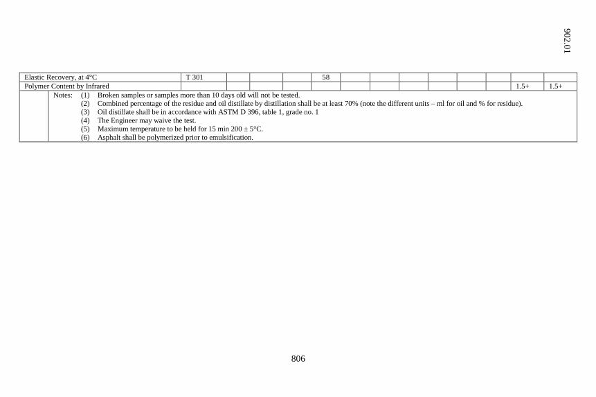
Elastic Recovery, at 4°C T 301 58 Polymer Content by Infrared 1.5+ 1.5+ Notes: (1) Broken samples or samples more than 10 days old will not be tested.
(2) Combined percentage of the residue and oil distillate by distillation shall be at least 70% (note the different units – ml for oil and % for residue). (3) Oil distillate shall be in accordance with ASTM D 396, table 1, grade no. 1 (4) The Engineer may waive the test. (5) Maximum temperature to be held for 15 min 200 ± 5°C. (6) Asphalt shall be polymerized prior to emulsification.
902.01
807
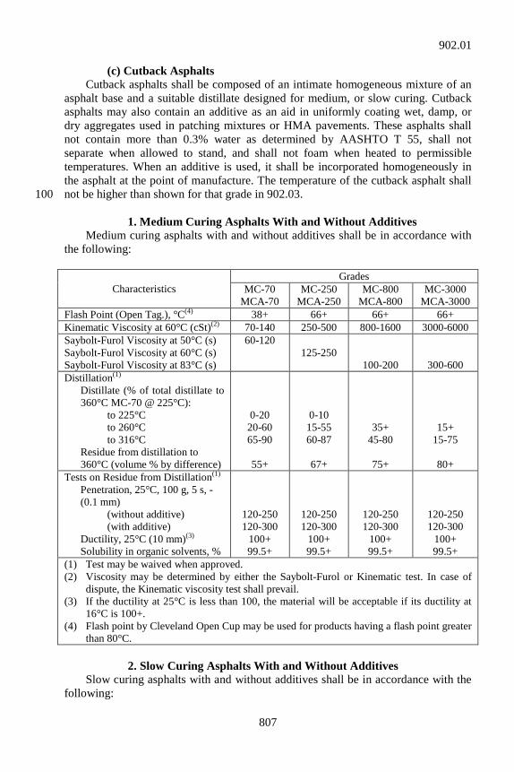
(c) Cutback Asphalts Cutback asphalts shall be composed of an intimate homogeneous mixture of an asphalt base and a suitable distillate designed for medium, or slow curing. Cutback asphalts may also contain an additive as an aid in uniformly coating wet, damp, or dry aggregates used in patching mixtures or HMA pavements. These asphalts shall not contain more than 0.3% water as determined by AASHTO T 55, shall not separate when allowed to stand, and shall not foam when heated to permissible temperatures. When an additive is used, it shall be incorporated homogeneously in the asphalt at the point of manufacture. The temperature of the cutback asphalt shall not be higher than shown for that grade in 902.03. 100 1. Medium Curing Asphalts With and Without Additives Medium curing asphalts with and without additives shall be in accordance with the following:
Characteristics Grades
MC-70 MCA-70
MC-250 MCA-250
MC-800 MCA-800
MC-3000 MCA-3000
Flash Point (Open Tag.), °C(4) 38+ 66+ 66+ 66+ Kinematic Viscosity at 60°C (cSt)(2) 70-140 250-500 800-1600 3000-6000 Saybolt-Furol Viscosity at 50°C (s) Saybolt-Furol Viscosity at 60°C (s) Saybolt-Furol Viscosity at 83°C (s)
60-120 125-250
100-200
300-600 Distillation(1) Distillate (% of total distillate to
360°C MC-70 @ 225°C): to 225°C to 260°C to 316°C Residue from distillation to
360°C (volume % by difference)
0-20 20-60 65-90
55+
0-10 15-55 60-87
67+
35+ 45-80
75+
15+ 15-75
80+
Tests on Residue from Distillation(1) Penetration, 25°C, 100 g, 5 s, - (0.1 mm) (without additive) (with additive) Ductility, 25°C (10 mm)(3) Solubility in organic solvents, %
120-250 120-300
100+ 99.5+
120-250 120-300
100+ 99.5+
120-250 120-300
100+ 99.5+
120-250 120-300
100+ 99.5+
(1) Test may be waived when approved. (2) Viscosity may be determined by either the Saybolt-Furol or Kinematic test. In case of
dispute, the Kinematic viscosity test shall prevail. (3) If the ductility at 25°C is less than 100, the material will be acceptable if its ductility at
16°C is 100+. (4) Flash point by Cleveland Open Cup may be used for products having a flash point greater
than 80°C. 2. Slow Curing Asphalts With and Without Additives Slow curing asphalts with and without additives shall be in accordance with the following:
902.01
808
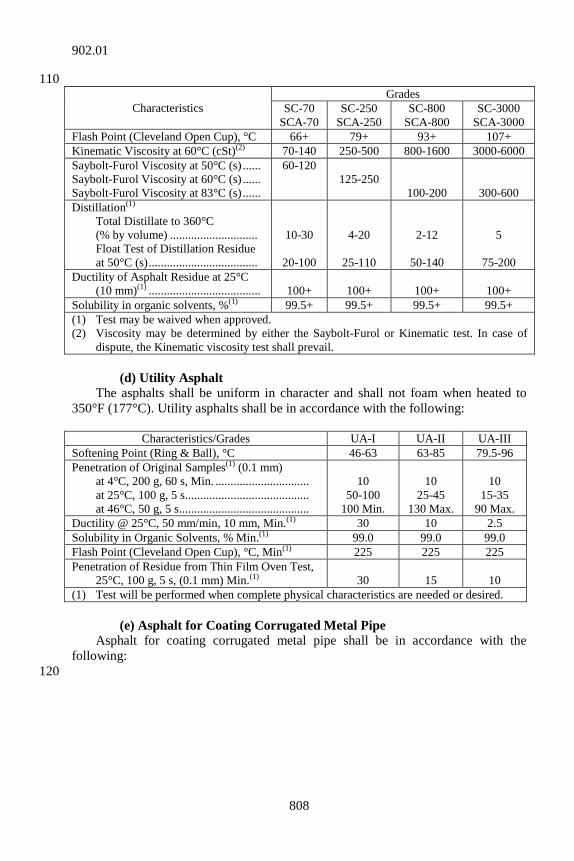
110
Characteristics Grades
SC-70 SCA-70
SC-250 SCA-250
SC-800 SCA-800
SC-3000 SCA-3000
Flash Point (Cleveland Open Cup), °C 66+ 79+ 93+ 107+ Kinematic Viscosity at 60°C (cSt)(2) 70-140 250-500 800-1600 3000-6000 Saybolt-Furol Viscosity at 50°C (s) ...... Saybolt-Furol Viscosity at 60°C (s) ...... Saybolt-Furol Viscosity at 83°C (s) ......
60-120 125-250
100-200
300-600 Distillation(1) Total Distillate to 360°C
(% by volume) ............................. Float Test of Distillation Residue
at 50°C (s) ....................................
10-30
20-100
4-20
25-110
2-12
50-140
5
75-200 Ductility of Asphalt Residue at 25°C (10 mm)(1) .....................................
100+
100+
100+
100+
Solubility in organic solvents, %(1) 99.5+ 99.5+ 99.5+ 99.5+ (1) Test may be waived when approved. (2) Viscosity may be determined by either the Saybolt-Furol or Kinematic test. In case of
dispute, the Kinematic viscosity test shall prevail. (d) Utility Asphalt The asphalts shall be uniform in character and shall not foam when heated to 350°F (177°C). Utility asphalts shall be in accordance with the following:
Characteristics/Grades UA-I UA-II UA-III Softening Point (Ring & Ball), °C 46-63 63-85 79.5-96 Penetration of Original Samples(1) (0.1 mm) at 4°C, 200 g, 60 s, Min. ............................... at 25°C, 100 g, 5 s ......................................... at 46°C, 50 g, 5 s ...........................................
10
50-100 100 Min.
10
25-45 130 Max.
10
15-35 90 Max.
Ductility @ 25°C, 50 mm/min, 10 mm, Min.(1) 30 10 2.5 Solubility in Organic Solvents, % Min.(1) 99.0 99.0 99.0 Flash Point (Cleveland Open Cup), °C, Min(1) 225 225 225 Penetration of Residue from Thin Film Oven Test, 25°C, 100 g, 5 s, (0.1 mm) Min.(1)
30
15
10
(1) Test will be performed when complete physical characteristics are needed or desired. (e) Asphalt for Coating Corrugated Metal Pipe Asphalt for coating corrugated metal pipe shall be in accordance with the following:
120
902.01
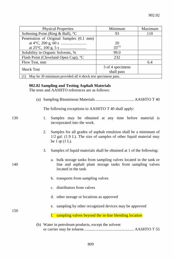
809
Physical Properties Minimum Maximum
Softening Point (Ring & Ball), °C 93 110 Penetration of Original Samples (0.1 mm) at 4°C, 200 g, 60 s ......................... at 25°C, 100 g, 5 s ..........................
20
35(1)
Solubility in Organic Solvents, % 99.0 Flash Point (Cleveland Open Cup), °C 232 Flow Test, mm 6.4
Shock Test 3 of 4 specimens shall pass
(1) May be 30 minimum provided all 4 shock test specimens pass. 902.02 Sampling and Testing Asphalt Materials The tests and AASHTO references are as follows: (a) Sampling Bituminous Materials ...................................... AASHTO T 40 The following exceptions to AASHTO T 40 shall apply: 1. Samples may be obtained at any time before material is 130
incorporated into the work. 2. Samples for all grades of asphalt emulsion shall be a minimum of
1/2 gal. (1.9 L). The size of samples of other liquid material may be 1 qt (1 L).
3. Samples of liquid materials shall be obtained at 1 of the following: a. bulk storage tanks from sampling valves located in the tank or
line and asphalt plant storage tanks from sampling valves 140 located in the tank
b. transports from sampling valves c. distributors from valves d. other storage or locations as approved e. sampling by other recognized devices may be approved 150 f. sampling valves beyond the in-line blending location (b) Water in petroleum products, except the solvent or carrier may be toluene ................................................. AASHTO T 55
902.02
810
(c) Density, Specific Gravity, or API Gravity of Crude Petroleum and Liquid Products by Hydrometer Method ...................................................... AASHTO T 227 (d) Specific Gravity of Semi-Solid Bituminous 160 Materials ........................................................................ AASHTO T 228 (e) Specific Gravity of Solid Pitch and Asphalt .................. AASHTO T 229 (f) Flash and Fire Points (Open Cup) 1. When the flash point is higher than 175°F (79°C), “Flash and Fire Points by Cleveland Open Cup” .............................................. AASHTO T 48 170 2. When the flash point is 175°F (79°C) or lower, “Flash Point with Tagliabue Open Cup” ................................................................ AASHTO T 79 (g) Softening Point of Bituminous Materials, Ring and Ball ................................................................... AASHTO T 53 (h) Penetration of Bituminous Materials ............................... AASHTO T 49 (i) Loss of Heating ................................................................ AASHTO T 47 180 (j) Solubility in Organic Solvents, except the solvent may be 1,1,1,-Trichloroethane ............................ AASHTO T 44 (k) Inorganic Matter or Ash .................................................. AASHTO T 59 (l) Saybolt-Furol Viscosity ................................................... AASHTO T 72 (m) Ductility of Binder Material, except that the conditioning period of the
specimens may be shortened, and that only 1 normal test will be 190 required. Shortened conditioning period: The specimen shall be allowed to cool in air for at least 30 min. It shall then be trimmed and placed in the water bath for a period of 60 to 90 min before testing. In case of failure or dispute, 3 normal tests will be required and specimens shall be conditioned as in AASHTO T 51.
(n) Distillation of Cutback Asphaltic Products, except the length of condenser tube may be 400 mm ± 24 mm ........ AASHTO T 78 (o) Float Test for Bituminous Materials ................................ AASHTO T 50 200
902.02
811
(p) Kinematic Viscosity of Asphalts ................................... AASHTO T 201 (q) Absolute Viscosity of Asphalts ..................................... AASHTO T 202 (r) Effect of Heat and Air on Asphalt Materials, Thin-Film Oven Test ..................................................... AASHTO T 179 (s) Effect of Heat and Air on a Moving Film of Asphalt, Rolling Thin Film Oven Test .......................... AASHTO T 240 210 (t) Testing Asphalt Emulsions .............................................. AASHTO T 59 The following exceptions to T 59 shall apply: 1. For the Residue by Distillation test, the specified aluminum alloy
still shall be the referee still. 2. When tests on the residue are not required, the percent of residue
for emulsion grades RS-2, AE-60, AE-90, and AE-T only, may be determined by the Residue by Evaporation test of AASHTO T 59. 220 The percent of residue shall be determined by the Residue of Distillation test in all cases of failure or dispute.
3. The stone coating test shall be performed as follows on a mixture
of 465 ± 1 g of reference stone and 35.0 ± 0.1 g of asphalt emulsion:
a. For AE-90 the mixture of stone and asphalt shall be mixed
vigorously for 5 min. At the end of the mixing period, the mix shall be rinsed by running sufficient tap water at the side of the 230 container to completely immerse the mix. The tap water shall then be poured off and the rinsing step repeated as necessary until the rinse water pours off essentially clear. The stone shall remain a minimum of 90% coated.
b. For AE-150 and AE-150-L, the mixture of stone and asphalt
shall be mixed vigorously for 5 min and then allowed to stand for 3 h. At the end of this time, the mixture shall again be mixed vigorously for 5 min. At the end of the mixing period, the mix shall be rinsed by running sufficient tap water at the 240 side of the container to completely immerse the mix. The tap water shall then be poured off and the rinsing step repeated as necessary until the rinse water pours off essentially clear. The stone shall remain a minimum of 90% coated for AE-150 and AE-150-L.
902.02
812
4. For the Demulsibility test, normally only 1 test will be required. In case of failure or dispute, the specified procedure in AASHTO T 59 will be followed.
250 5. For oil portion from Residue by Distillation, report the number of
milliliters of oil per 100 g of emulsion. (u) For coating test for cutback asphalts with additive, 20 g of 20 to 30
mesh Ottawa sand shall be placed in a clean 2 oz (60 mL) wide-mouthed jar and covered with 25 g of distilled water at room temperature. One gram of the liquid asphalt to be tested shall be placed gently upon the surface of the water so that it floats and does not contact the sand. The lid shall then be placed on the jar and tightened securely. If the liquid asphalt to be tested is grade 70 or 250, the jar and 260 contents shall be shaken vigorously for 30 s. If the grade is 800 or 3000, the jar and contents shall be immersed in a 115°F (46°C) water bath for 5 min to bring the contents of the jar to a temperature of approximately 100°F (38°C). The jar shall then be shaken vigorously for 30 s. After shaking, the asphalt coating on the sand shall be observed under a constant, strong light. Complete coating of the sand is required.
(v) Stripping tests for HMA mixtures using binder materials, with or
without additives, shall be performed as follows: 270 1. Test 1. A sample of produced mixture, 500 g, minimum, shall be
obtained for testing. The size of test specimen and the amount of distilled water shall be:
Approximate Minimum Amount of Size of Weight of Distilled Aggregate Test Specimen Water Sand 100 g 400 mL 280 12 100 g 400 mL 11 150 g 600 mL 9 200 g 600 mL Place the specimen in the boiling distilled water and stir with a glass
rod at the rate of 1 revolution per second for 3 min. The aggregate shall retain a minimum of 90% of its asphalt film compared with the remainder of the sample, upon completion of this procedure.
2. Test 2. Approximately 500 g of produced mixture shall be heated to 290
250°F (121°C) in a laboratory oven for 2 h; stirred and cooled to 200°F (92.5°C). Then a portion of the mix shall be placed in boiling distilled
902.02

813
water, quantity of mix and quantity of boiling water shall be as specified in Test 1, and stirred with a glass rod at the rate of 1 revolution per second for 3 min. The aggregate shall retain a minimum of 90% of its asphalt film compared with the remainder of the sample, upon completion of this procedure.
Note: The purpose of these tests is to determine the relative compatibility
of the aggregate and asphalt, and to detect tendency of Asphalt 300 Emulsions to re-emulsify. Test 2 may be performed as a method of determining whether compatibility can be achieved, Test 1 having given unsatisfactory results.
(w) Penetrating Ability of AE-PL. 1. Apparatus and Equipment: a. Sand mixture: 310 (1) Dry Ottawa Sand (AASHTO T 106) ....................... 90 parts (2) Dry Reference Limestone Dust, portion passing #50
(300 mm) sieve only. Reference Limestone Dust used by the Department is Limestone Calcium Carbonate manufactured by France Stone Co. The Department will furnish approximately 5 lb (2.3 kg) of Reference Limestone Dust upon request. ................................. 10 parts
(3) Water ......................................................................... 3 parts 320 b. Container, 6 oz (170 g) ointment tin c. Ruler or other measuring device d. Timing device readable in seconds e. Compacting Device. Rimac Spring Tester or other device
suitable for compacting sand by applying a 20 psi (140 kPa) load. The compacting device shall include an adapter 330 consisting of 2 metal discs slightly smaller in diameter than a 6 oz (170 g) ointment tin separated by a spacer 1 to 2 in. (25 to 50 mm). The 2.5 in. (65 mm) diameter discs used in determining weight of coating in AASHTO T 65 or ASTM A 90 are satisfactory.
f. Small, square ended spatula or putty knife
902.02
814
2. Procedure: 340 Thoroughly mix Standard Ottawa Sand, Reference Limestone
Dust, and water. Weigh 190 ± 1 g of sand mixture into a 6 oz (170 g) ointment tin. Level surface of sand with a spatula. Place the compacting adapter on the sand surface and slowly, over a period of about 5 s, compact the sand until the 20 psi (140 kPa) load is achieved, which is approximately 100 lb (45 kg) on the Rimac Spring Tester. Remove the compacting device, avoiding disturbance to the sand surface. Quickly pour 12 g of the emulsion from a height of about 4 in. (100 mm) onto top of sand mixture. 350 Start timer at start of pour. Stop timer when all emulsion penetrates into sand mixture. Delay 2 min then remove sand and mixture from 1 side of ointment tin, about 1/2 of mixture. Measure to determine average depth of penetration into sand mixture. Penetration time shall be 100 s or less; penetration depth shall be 1/4 in. (6 mm) or more.
(x) Flow Test for Asphalt for Coating Corrugated Metal Pipe ...................................................................... AASHTO T 190 360 (y) Shock Test for Asphalt for Coating Corrugated Metal Pipe ...................................................................... AASHTO T 190 (z) Viscosity Determinations of Unfilled Asphalts Using the Brookfield Thermosel Apparatus .................. AASHTO T 316 (aa) Determining the Rheological Properties of Asphalt Binder Using a Dynamic Shear Rheometer............ AASHTO T 315 (bb) Accelerated Aging of Asphalt Binder Using a 370 Pressurized Aging Vessel ......................................... AASHTO R 28 (cc) Determining the Flexural Creep Stiffness of Asphalt Binder Using the Bending Beam Rheometer .............................................................. AASHTO T 313 902.03 Application Temperatures Binder materials for the several applications indicated in the specifications shall be applied at temperatures not to exceed those shown in the following:
380
902.03
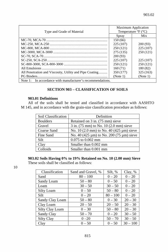
815
Type and Grade of Material Maximum Application Temperature °F (°C)
Spray Mix MC-70, MCA-70 ..................................................................... MC-250, MCA-250 ................................................................. MC-800, MCA-800 ................................................................. MC-3000, MCA-3000 ............................................................. SC-70, SCA-70 ........................................................................ SC-250, SCA-250 .................................................................... SC-800-3000, SCA-800-3000 ................................................. All Emulsions .......................................................................... All Penetration and Viscosity, Utility and Pipe Coating .......... PG Binders...............................................................................
150 (66) 225 (107) 250 (121) 275 (135) 200 (93) 225 (107) 250 (121) 160 (71) 350 (177) (Note 1)
200 (93) 225 (107) 250 (121) 225 (107) 250 (121) 180 (82) 325 (163) (Note 1)
Note 1: In accordance with manufacturer’s recommendations.
SECTION 903 – CLASSIFICATION OF SOILS 903.01 Definitions All of the soils shall be tested and classified in accordance with AASHTO M 145, and in accordance with the grain-size classification procedure as follows:
Soil Classification Definition Boulders Retained on 3 in. (75 mm) sieve Gravel 3 in. (75 mm) to No. 10 (2.0 mm) sieve Coarse Sand No. 10 (2.0 mm) to No. 40 (425 µm) sieve Fine Sand No. 40 (425 µm) to No. 200 (75 µm) sieve Silt 0.075 to 0.002 mm Clay Smaller than 0.002 mm Colloids Smaller than 0.001 mm
903.02 Soils Having 0% to 19% Retained on No. 10 (2.00 mm) Sieve These soils shall be classified as follows: 10
Classification Sand and Gravel, % Silt, % Clay, % Sand 80 – 100 0 – 20 0 – 20 Sandy Loam 50 – 80 0 – 50 0 – 20 Loam 30 – 50 30 – 50 0 – 20 Silty Loam 0 – 50 50 – 80 0 – 20 Silt 0 – 20 80 – 100 0 – 20 Sandy Clay Loam 50 – 80 0 – 30 20 – 30 Clay Loam 20 – 50 20 – 50 20 – 30 Silty Clay Loam 0 – 30 50 – 80 20 – 30 Sandy Clay 50 – 70 0 – 20 30 – 50 Silty Clay 0 –20 50 – 70 30 – 50 Clay 0 – 50 0 – 50 30 – 100
903.02
816
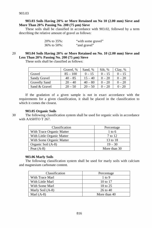
903.03 Soils Having 20% or More Retained on No 10 (2.00 mm) Sieve and More Than 20% Passing No. 200 (75 µm) Sieve These soils shall be classified in accordance with 903.02, followed by a term describing the relative amount of gravel as follows: 20% to 35%: “with some gravel” 36% to 50%: “and gravel” 903.04 Soils Having 20% or More Retained on No. 10 (2.00 mm) Sieve and 20 Less Than 20% Passing No. 200 (75 µm) Sieve These soils shall be classified as follows:
Gravel, % Sand, % Silt, % Clay, % Gravel 85 – 100 0 – 15 0 – 15 0 – 15 Sandy Gravel 40 – 85 15 – 40 0 – 20 0 – 20 Gravelly Sand 20 – 40 40 – 80 0 – 20 0 – 20 Sand & Gravel 20 – 50 20 – 50 0 – 20 0 - 20
If the gradation of a given sample is not in exact accordance with the requirements for a given classification, it shall be placed in the classification to which it comes the closest. 903.05 Organic Soils The following classification system shall be used for organic soils in accordance 30 with AASHTO T 267.
Classification Percentage With Trace Organic Matter 1 to 6 With Little Organic Matter 7 to 12 With Some Organic Matter 13 to 18 Organic Soil (A-8) 19 – 30 Peat (A-8) More than 30
903.06 Marly Soils The following classification system shall be used for marly soils with calcium and magnesium carbonate content.
Classification Percentage With Trace Marl 1 to 9 With Little Marl 10 to 17 With Some Marl 18 to 25 Marly Soil (A-8) 26 to 40 Marl (A-8) More than 40
903.03
817
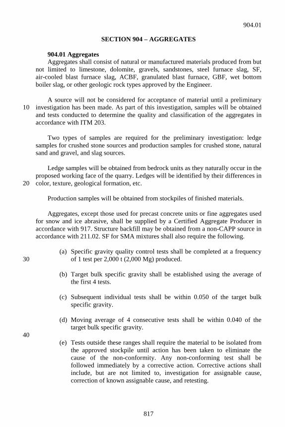
SECTION 904 – AGGREGATES 904.01 Aggregates Aggregates shall consist of natural or manufactured materials produced from but not limited to limestone, dolomite, gravels, sandstones, steel furnace slag, SF, air-cooled blast furnace slag, ACBF, granulated blast furnace, GBF, wet bottom boiler slag, or other geologic rock types approved by the Engineer. A source will not be considered for acceptance of material until a preliminary investigation has been made. As part of this investigation, samples will be obtained 10 and tests conducted to determine the quality and classification of the aggregates in accordance with ITM 203. Two types of samples are required for the preliminary investigation: ledge samples for crushed stone sources and production samples for crushed stone, natural sand and gravel, and slag sources. Ledge samples will be obtained from bedrock units as they naturally occur in the proposed working face of the quarry. Ledges will be identified by their differences in color, texture, geological formation, etc. 20 Production samples will be obtained from stockpiles of finished materials. Aggregates, except those used for precast concrete units or fine aggregates used for snow and ice abrasive, shall be supplied by a Certified Aggregate Producer in accordance with 917. Structure backfill may be obtained from a non-CAPP source in accordance with 211.02. SF for SMA mixtures shall also require the following. (a) Specific gravity quality control tests shall be completed at a frequency
of 1 test per 2,000 t (2,000 Mg) produced. 30 (b) Target bulk specific gravity shall be established using the average of
the first 4 tests. (c) Subsequent individual tests shall be within 0.050 of the target bulk
specific gravity. (d) Moving average of 4 consecutive tests shall be within 0.040 of the
target bulk specific gravity. 40 (e) Tests outside these ranges shall require the material to be isolated from
the approved stockpile until action has been taken to eliminate the cause of the non-conformity. Any non-conforming test shall be followed immediately by a corrective action. Corrective actions shall include, but are not limited to, investigation for assignable cause, correction of known assignable cause, and retesting.
904.01
818
(f) If it is determined that a new target is necessary, a request shall be made in writing to the District Testing Engineer to establish the new target. 50
Dolomite aggregates are defined as carbonate rock containing at least 10.3% elemental magnesium when tested in accordance with ITM 205. Polish resistant aggregates are defined as those aggregates in accordance with ITM 214. Aggregates meeting these requirements will be maintained on the Department’s list of approved Polish Resistant Aggregates. Sandstone aggregates shall only be used in HMA surface or SMA surface mixtures. Sandstone aggregates are defined as a sedimentary rock composed of 60 siliceous sandgrains containing quartz, chert, and quartzose rock fragments in a carbonate matrix or cemented with silica, calcite, or dolomite. The Office of Materials Management will determine identification of sandstone. Steel furnace slag, SF, may be used in aggregate shoulders, HMA surface or SMA surface mixtures, dumped riprap, and snow and ice abrasives. SF slag coarse aggregate may be used in HMA base and HMA intermediate mixtures if the deleterious content is less than 4.0 % when tested in accordance with ITM 219. RAP with steel slag may be used in accordance with 401.06, 402.08 and 410.06. 70 Adjustments in weight (mass) shall be made to compensate for the difference in specific gravity of slag compared to natural aggregate when payment is on a weight (mass) basis. The following typical values for specific gravity will be used: natural aggregate both fine and coarse, 2.6; ACBF slag coarse aggregate, 2.3; ACBF slag fine aggregate, 2.6; GBF slag fine aggregate, 2.1; and SF slag both fine and coarse, 3.4. The contract quantity shall not be adjusted on any pay item less than 500 t (500 Mg). When slag is furnished as an aggregate, the approximate quantity of tons (megagrams) to be supplied will be determined by multiplying the pay item quantity 80 of tons (megagrams) by the specific gravity of slag divided by 2.6. The adjusted contract quantities will be determined by multiplying the accepted quantity of tons (megagrams) by 2.6 divided by the specific gravity of the slag. At time of use, aggregates shall be free from lumps or crusts of hardened or frozen materials. Composite stockpiling of natural sand fine aggregate from multiple sources into 1 stockpile will be allowed provided the fine aggregates are within a range of 0.10 for the bulk specific gravity (dry) and a range of 1.0% for the absorption. The range 90 of bulk specific gravity (dry) and absorption values shall be the difference between the highest and lowest value, respectively, of the fine aggregate sources within the stockpile. A written request for the composite stockpiling shall be made to the Office of Materials Management.
904.01
819
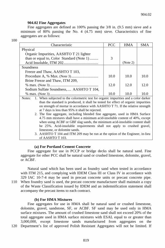
904.02 Fine Aggregates Fine aggregates are defined as 100% passing the 3/8 in. (9.5 mm) sieve and a minimum of 80% passing the No. 4 (4.75 mm) sieve. Characteristics of fine aggregates are as follows: 100
(a) For Portland Cement Concrete Fine aggregate for use in PCCP or bridge decks shall be natural sand. Fine aggregate for other PCC shall be natural sand or crushed limestone, dolomite, gravel, or ACBF. Natural sand which has been used as foundry sand when tested in accordance with ITM 215, and complying with IDEM Class III or Class IV in accordance with 329 IAC 10-7-4 may be used in precast concrete units or precast concrete pipe. When foundry sand is used, the precast concrete manufacturer shall maintain a copy 110 of the Waste Classification issued by IDEM and an indemnification statement shall accompany the precast items to each contract. (b) For HMA Mixtures Fine aggregates for use in HMA shall be natural sand or crushed limestone, dolomite, gravel, sandstone, SF, or ACBF. SF sand may be used only in HMA surface mixtures. The amount of crushed limestone sand shall not exceed 20% of the total aggregate used in HMA surface mixtures with ESAL equal to or greater than 3,000,000, except limestone sands manufactured from aggregates on the Department’s list of approved Polish Resistant Aggregates will not be limited. If 120
Characteristic PCC HMA SMA Physical Organic Impurities, AASHTO T 21 lighter
than or equal to, Color Standard (Note 1) ......... Acid Insoluble, ITM 202 ....................................
3
(Note 2)
Soundness Freeze and Thaw, AASHTO T 103,
Procedure A, % Max. (Note 3) ............................ Brine Freeze and Thaw, ITM 209,
% max. (Note 3) .................................................. Sodium Sulfate Soundness, .... AASHTO T 104,
% max. (Note 3) ..................................................
10.0
12.0
10.0
10.0
12.0
10.0
10.0
12.0
10.0 Notes: 1. When subjected to the colormetric test for organic impurities and a color darker
than the standard is produced, it shall be tested for effect of organic impurities on strength of mortar in accordance with AASHTO T 71. If the relative strength at 7 days is less than 95% it shall be rejected.
2. The fine aggregate, including blended fine aggregate, used in HMA Surface 4.75 mm mixtures shall have a minimum acid-insoluble content of 40%, except when using ACBF or GBF slag sands, the minimum acid-insoluble content shall be 25%. Acid-insoluble requirements shall not apply to crushed gravel, limestone, or dolomite sands.
3. AASHTO T 104 and ITM 209 may be run at the option of the Engineer, in-lieu of AASHTO T 103.
904.02
820
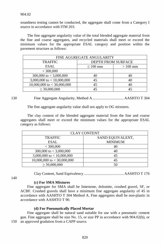
soundness testing cannot be conducted, the aggregate shall come from a Category I source in accordance with ITM 203. The fine aggregate angularity value of the total blended aggregate material from the fine and coarse aggregates, and recycled materials shall meet or exceed the minimum values for the appropriate ESAL category and position within the pavement structure as follows:
FINE AGGREGATE ANGULARITY TRAFFIC
ESAL DEPTH FROM SURFACE
≤ 100 mm > 100 mm < 300,000
300,000 to < 3,000,000 40 40 3,000,000 to < 10,000,000 45 40
10,000,000 to < 30,000,000 45 40 ≥ 30,000,000 45 45
Fine Aggregate Angularity, Method A ................................. AASHTO T 304 130 The fine aggregate angularity value shall not apply to OG mixtures. The clay content of the blended aggregate material from the fine and coarse aggregates shall meet or exceed the minimum values for the appropriate ESAL category as follows:
CLAY CONTENT TRAFFIC
ESAL SAND EQUIVALENT,
MINIMUM < 300,000 40
300,000 to < 3,000,000 40 3,000,000 to < 10,000,000 45 10,000,000 to < 30,000,000 45
≥ 30,000,000 50 Clay Content, Sand Equivalency .......................................... AASHTO T 176 140 (c) For SMA Mixtures Fine aggregate for SMA shall be limestone, dolomite, crushed gravel, SF, or ACBF. Crushed gravels shall have a minimum fine aggregate angularity of 45 in accordance with AASHTO T 304 Method A. Fine aggregates shall be non-plastic in accordance with AASHTO T 90. (d) For Pneumatically Placed Mortar Fine aggregate shall be natural sand suitable for use with a pneumatic cement gun. Fine aggregate shall be size No. 15, or size PP in accordance with 904.02(h), or an approved gradation from a CAPP source. 150
904.02
821
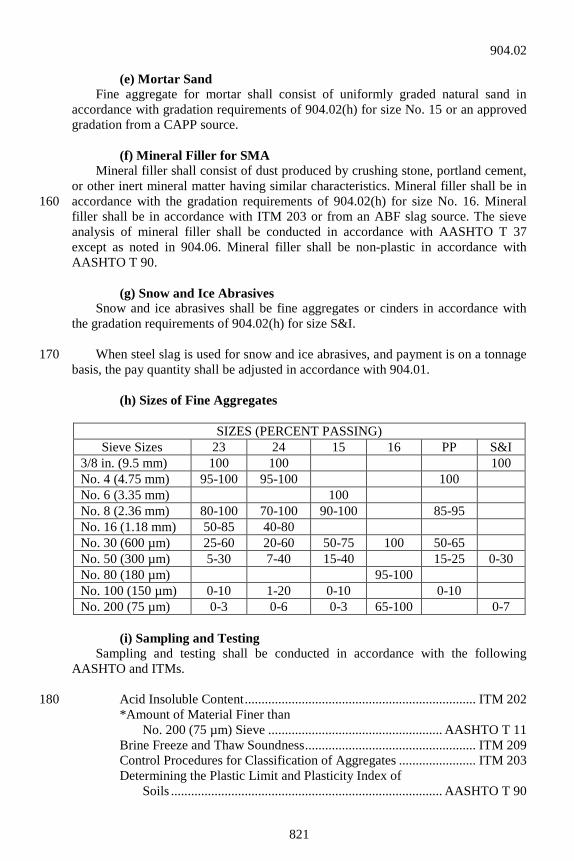
(e) Mortar Sand Fine aggregate for mortar shall consist of uniformly graded natural sand in accordance with gradation requirements of 904.02(h) for size No. 15 or an approved gradation from a CAPP source. (f) Mineral Filler for SMA Mineral filler shall consist of dust produced by crushing stone, portland cement, or other inert mineral matter having similar characteristics. Mineral filler shall be in accordance with the gradation requirements of 904.02(h) for size No. 16. Mineral 160 filler shall be in accordance with ITM 203 or from an ABF slag source. The sieve analysis of mineral filler shall be conducted in accordance with AASHTO T 37 except as noted in 904.06. Mineral filler shall be non-plastic in accordance with AASHTO T 90. (g) Snow and Ice Abrasives Snow and ice abrasives shall be fine aggregates or cinders in accordance with the gradation requirements of 904.02(h) for size S&I. When steel slag is used for snow and ice abrasives, and payment is on a tonnage 170 basis, the pay quantity shall be adjusted in accordance with 904.01. (h) Sizes of Fine Aggregates
SIZES (PERCENT PASSING) Sieve Sizes 23 24 15 16 PP S&I
3/8 in. (9.5 mm) 100 100 100 No. 4 (4.75 mm) 95-100 95-100 100 No. 6 (3.35 mm) 100 No. 8 (2.36 mm) 80-100 70-100 90-100 85-95 No. 16 (1.18 mm) 50-85 40-80 No. 30 (600 µm) 25-60 20-60 50-75 100 50-65 No. 50 (300 µm) 5-30 7-40 15-40 15-25 0-30 No. 80 (180 µm) 95-100 No. 100 (150 µm) 0-10 1-20 0-10 0-10 No. 200 (75 µm) 0-3 0-6 0-3 65-100 0-7
(i) Sampling and Testing Sampling and testing shall be conducted in accordance with the following AASHTO and ITMs. Acid Insoluble Content ..................................................................... ITM 202 180 *Amount of Material Finer than No. 200 (75 µm) Sieve .................................................... AASHTO T 11 Brine Freeze and Thaw Soundness ................................................... ITM 209 Control Procedures for Classification of Aggregates ....................... ITM 203 Determining the Plastic Limit and Plasticity Index of Soils ................................................................................. AASHTO T 90
904.02
822
Mortar Strength ...................................................................... AASHTO T 71 Organic Impurities .................................................................. AASHTO T 21 Sampling Aggregates................................................................ AASHTO T 2 Sampling Stockpiled Aggregates...................................................... ITM 207 190 *Sieve Analysis of Aggregate ................................................ AASHTO T 27 *Sieve Analysis of Mineral Filler ........................................... AASHTO T 37 *Soundness ................................................................ AASHTO T 103, T 104 Specific Gravity and Absorption, Fine Aggregate .................. AASHTO T 84
* Except as noted in 904.06. 904.03 Coarse Aggregates Course aggregates are defined as having a minimum of 20% retained on the No. 4 (4.75 mm) sieve. Coarse aggregates shall not contain adherent fines that are detrimental to the end product as defined in ITM 211. 200 The coarse aggregate shall comply with the quality requirements and the additional requirements in accordance with 904.03(a). However, coarse aggregate may be rejected based on previous performance service records. Class AP is defined as the highest classification and Class F the lowest. Blending of material for compliance with gradation or crushed particle requirements may be permitted when requested in writing. Blending of aggregate products to improve the quality classification of the finished product will not be permitted.
904.03
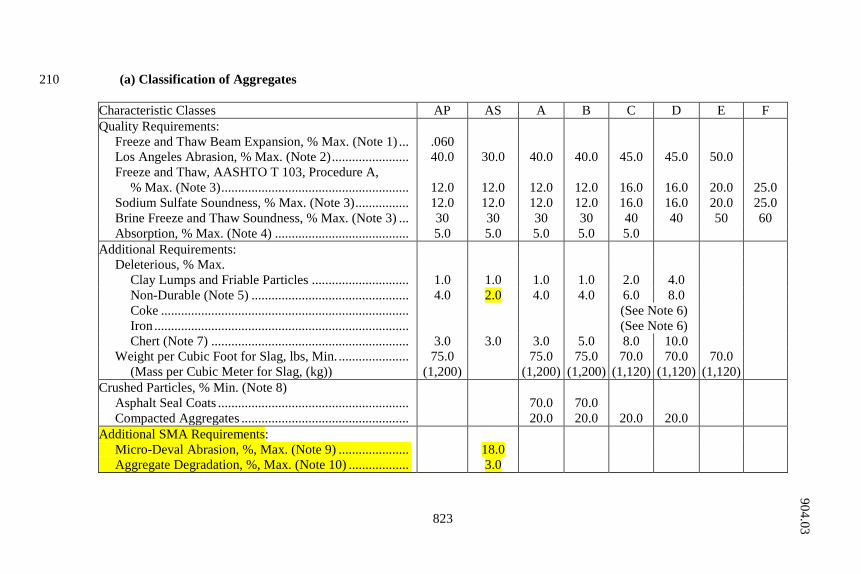
823
(a) Classification of Aggregates 210
Characteristic Classes AP AS A B C D E F Quality Requirements: Freeze and Thaw Beam Expansion, % Max. (Note 1) ... .060 Los Angeles Abrasion, % Max. (Note 2) ....................... 40.0 30.0 40.0 40.0 45.0 45.0 50.0 Freeze and Thaw, AASHTO T 103, Procedure A, % Max. (Note 3) ........................................................ 12.0 12.0 12.0 12.0 16.0 16.0 20.0 25.0 Sodium Sulfate Soundness, % Max. (Note 3) ................ 12.0 12.0 12.0 12.0 16.0 16.0 20.0 25.0 Brine Freeze and Thaw Soundness, % Max. (Note 3) ... 30 30 30 30 40 40 50 60 Absorption, % Max. (Note 4) ........................................ 5.0 5.0 5.0 5.0 5.0 Additional Requirements: Deleterious, % Max. Clay Lumps and Friable Particles ............................. 1.0 1.0 1.0 1.0 2.0 4.0 Non-Durable (Note 5) ............................................... 4.0 2.0 4.0 4.0 6.0 8.0 Coke .......................................................................... (See Note 6) Iron ............................................................................ (See Note 6) Chert (Note 7) ........................................................... 3.0 3.0 3.0 5.0 8.0 10.0 Weight per Cubic Foot for Slag, lbs, Min. ..................... 75.0 75.0 75.0 70.0 70.0 70.0 (Mass per Cubic Meter for Slag, (kg)) (1,200) (1,200) (1,200) (1,120) (1,120) (1,120) Crushed Particles, % Min. (Note 8) Asphalt Seal Coats ......................................................... 70.0 70.0 Compacted Aggregates .................................................. 20.0 20.0 20.0 20.0 Additional SMA Requirements: Micro-Deval Abrasion, %, Max. (Note 9) ..................... 18.0 Aggregate Degradation, %, Max. (Note 10) .................. 3.0
904.03
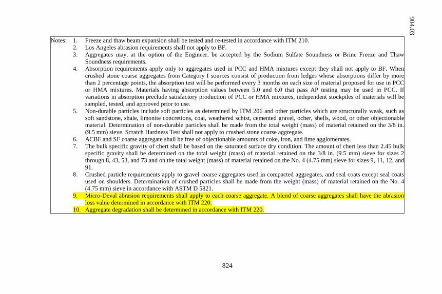
824
Notes: 1. Freeze and thaw beam expansion shall be tested and re-tested in accordance with ITM 210. 2. Los Angeles abrasion requirements shall not apply to BF. 3. Aggregates may, at the option of the Engineer, be accepted by the Sodium Sulfate Soundness or Brine Freeze and Thaw
Soundness requirements. 4. Absorption requirements apply only to aggregates used in PCC and HMA mixtures except they shall not apply to BF. When
crushed stone coarse aggregates from Category I sources consist of production from ledges whose absorptions differ by more than 2 percentage points, the absorption test will be performed every 3 months on each size of material proposed for use in PCC or HMA mixtures. Materials having absorption values between 5.0 and 6.0 that pass AP testing may be used in PCC. If variations in absorption preclude satisfactory production of PCC or HMA mixtures, independent stockpiles of materials will be sampled, tested, and approved prior to use.
5. Non-durable particles include soft particles as determined by ITM 206 and other particles which are structurally weak, such as soft sandstone, shale, limonite concretions, coal, weathered schist, cemented gravel, ocher, shells, wood, or other objectionable material. Determination of non-durable particles shall be made from the total weight (mass) of material retained on the 3/8 in. (9.5 mm) sieve. Scratch Hardness Test shall not apply to crushed stone coarse aggregate.
6. ACBF and SF coarse aggregate shall be free of objectionable amounts of coke, iron, and lime agglomerates. 7. The bulk specific gravity of chert shall be based on the saturated surface dry condition. The amount of chert less than 2.45 bulk
specific gravity shall be determined on the total weight (mass) of material retained on the 3/8 in. (9.5 mm) sieve for sizes 2 through 8, 43, 53, and 73 and on the total weight (mass) of material retained on the No. 4 (4.75 mm) sieve for sizes 9, 11, 12, and 91.
8. Crushed particle requirements apply to gravel coarse aggregates used in compacted aggregates, and seal coats except seal coats used on shoulders. Determination of crushed particles shall be made from the weight (mass) of material retained on the No. 4 (4.75 mm) sieve in accordance with ASTM D 5821.
9. Micro-Deval abrasion requirements shall apply to each coarse aggregate. A blend of coarse aggregates shall have the abrasion loss value determined in accordance with ITM 220.
10. Aggregate degradation shall be determined in accordance with ITM 220.
904.03
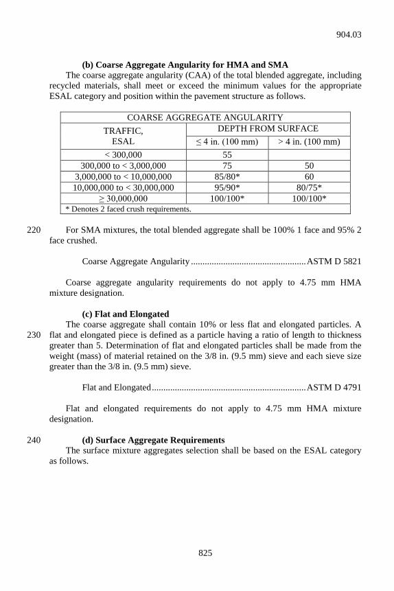
825
(b) Coarse Aggregate Angularity for HMA and SMA The coarse aggregate angularity (CAA) of the total blended aggregate, including recycled materials, shall meet or exceed the minimum values for the appropriate ESAL category and position within the pavement structure as follows.
COARSE AGGREGATE ANGULARITY TRAFFIC,
ESAL DEPTH FROM SURFACE
≤ 4 in. (100 mm) > 4 in. (100 mm) < 300,000 55
300,000 to < 3,000,000 75 50 3,000,000 to < 10,000,000 85/80* 60 10,000,000 to < 30,000,000 95/90* 80/75*
≥ 30,000,000 100/100* 100/100* * Denotes 2 faced crush requirements.
For SMA mixtures, the total blended aggregate shall be 100% 1 face and 95% 2 220 face crushed. Coarse Aggregate Angularity .................................................. ASTM D 5821 Coarse aggregate angularity requirements do not apply to 4.75 mm HMA mixture designation. (c) Flat and Elongated The coarse aggregate shall contain 10% or less flat and elongated particles. A flat and elongated piece is defined as a particle having a ratio of length to thickness 230 greater than 5. Determination of flat and elongated particles shall be made from the weight (mass) of material retained on the 3/8 in. (9.5 mm) sieve and each sieve size greater than the 3/8 in. (9.5 mm) sieve. Flat and Elongated ................................................................... ASTM D 4791 Flat and elongated requirements do not apply to 4.75 mm HMA mixture designation. (d) Surface Aggregate Requirements 240 The surface mixture aggregates selection shall be based on the ESAL category as follows.
904.03
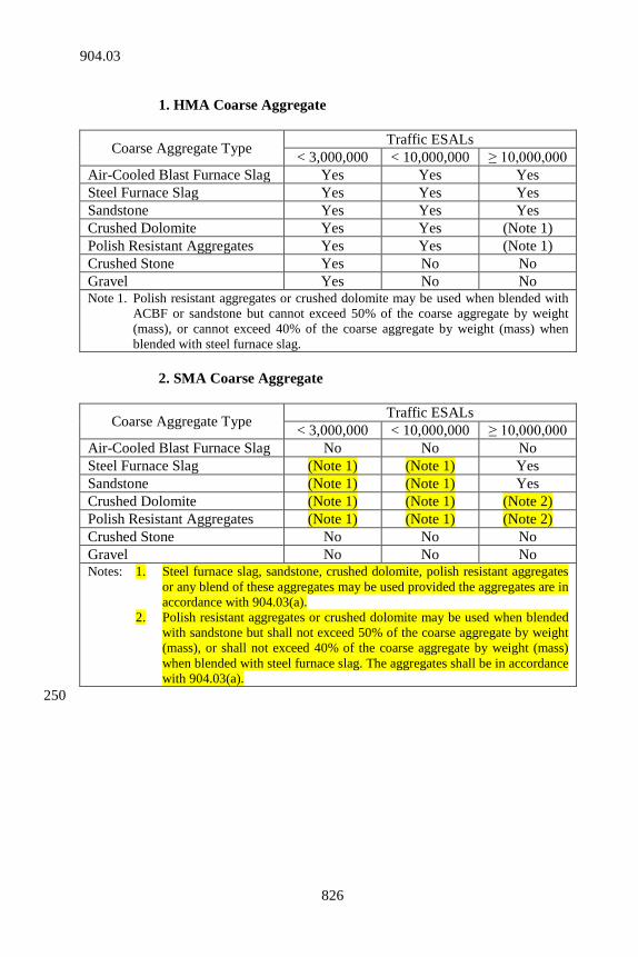
826
1. HMA Coarse Aggregate
Coarse Aggregate Type Traffic ESALs < 3,000,000 < 10,000,000 ≥ 10,000,000
Air-Cooled Blast Furnace Slag Yes Yes Yes Steel Furnace Slag Yes Yes Yes Sandstone Yes Yes Yes Crushed Dolomite Yes Yes (Note 1) Polish Resistant Aggregates Yes Yes (Note 1) Crushed Stone Yes No No Gravel Yes No No Note 1. Polish resistant aggregates or crushed dolomite may be used when blended with
ACBF or sandstone but cannot exceed 50% of the coarse aggregate by weight (mass), or cannot exceed 40% of the coarse aggregate by weight (mass) when blended with steel furnace slag.
2. SMA Coarse Aggregate
Coarse Aggregate Type Traffic ESALs < 3,000,000 < 10,000,000 ≥ 10,000,000
Air-Cooled Blast Furnace Slag No No No Steel Furnace Slag (Note 1) (Note 1) Yes Sandstone (Note 1) (Note 1) Yes Crushed Dolomite (Note 1) (Note 1) (Note 2) Polish Resistant Aggregates (Note 1) (Note 1) (Note 2) Crushed Stone No No No Gravel No No No Notes: 1. Steel furnace slag, sandstone, crushed dolomite, polish resistant aggregates
or any blend of these aggregates may be used provided the aggregates are in accordance with 904.03(a).
2. Polish resistant aggregates or crushed dolomite may be used when blended with sandstone but shall not exceed 50% of the coarse aggregate by weight (mass), or shall not exceed 40% of the coarse aggregate by weight (mass) when blended with steel furnace slag. The aggregates shall be in accordance with 904.03(a).
250
904.03
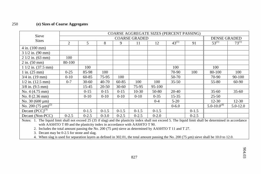
827
(e) Sizes of Coarse Aggregates 250
Sieve Sizes
COARSE AGGREGATE SIZES (PERCENT PASSING) COARSE GRADED DENSE GRADED
2 5 8 9 11 12 43(1) 91 53(1) 73(1) 4 in. (100 mm) 3 1/2 in. (90 mm) 2 1/2 in. (63 mm) 100 2 in. (50 mm) 80-100 1 1/2 in. (37.5 mm) 100 100 100 1 in. (25 mm) 0-25 85-98 100 70-90 100 80-100 100 3/4 in. (19 mm) 0-10 60-85 75-95 100 50-70 70-90 90-100 1/2 in. (12.5 mm) 0-7 30-60 40-70 60-85 100 100 35-50 55-80 60-90 3/8 in. (9.5 mm) 15-45 20-50 30-60 75-95 95-100 No. 4 (4.75 mm) 0-15 0-15 0-15 10-30 50-80 20-40 35-60 35-60 No. 8 (2.36 mm) 0-10 0-10 0-10 0-10 0-35 15-35 25-50 No. 30 (600 µm) 0-4 5-20 12-30 12-30 No. 200 (75 µm)(2) 0-6.0 5.0-10.0(4) 5.0-12.0 Decant (PCC)(3) 0-1.5 0-1.5 0-1.5 0-1.5 0-1.5 0-1.5 Decant (Non-PCC) 0-2.5 0-2.5 0-3.0 0-2.5 0-2.5 0-2.0 0-2.5 Notes: 1. The liquid limit shall not exceed 25 (35 if slag) and the plasticity index shall not exceed 5. The liquid limit shall be determined in accordance
with AASHTO T 89 and the plasticity index in accordance with AASHTO T 90. 2. Includes the total amount passing the No. 200 (75 µm) sieve as determined by AASHTO T 11 and T 27. 3. Decant may be 0-2.5 for stone and slag. 4. When slag is used for separation layers as defined in 302.01, the total amount passing the No. 200 (75 µm) sieve shall be 10.0 to 12.0.
904.03
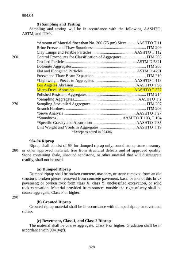
828
(f) Sampling and Testing Sampling and testing will be in accordance with the following AASHTO, ASTM, and ITMs. *Amount of Material finer than No. 200 (75 µm) Sieve ........ AASHTO T 11 Brine Freeze and Thaw Soundness ................................................... ITM 209 Clay Lumps and Friable Particles ......................................... AASHTO T 112 Control Procedures for Classification of Aggregates ....................... ITM 203 260 Crushed Particles ..................................................................... ASTM D 5821 Dolomite Aggregates ........................................................................ ITM 205 Flat and Elongated Particles .................................................... ASTM D 4791 Freeze and Thaw Beam Expansion .................................................. ITM 210 *Lightweight Pieces in Aggregates ...................................... AASHTO T 113 Los Angeles Abrasion ............................................................ AASHTO T 96 Micro-Deval Abrasion .......................................................... AASHTO T 327 Polished Resistant Aggregates.......................................................... ITM 214 *Sampling Aggregates .............................................................. AASHTO T 2 Sampling Stockpiled Aggregates...................................................... ITM 207 270 Scratch Hardness .............................................................................. ITM 206 *Sieve Analysis ...................................................................... AASHTO T 27 *Soundness ................................................................ AASHTO T 103, T 104 *Specific Gravity and Absorption .......................................... AASHTO T 85 Unit Weight and Voids in Aggregates .................................... AASHTO T 19
*Except as noted in 904.06 904.04 Riprap Riprap shall consist of SF for dumped riprap only, sound stone, stone masonry, or other approved material, free from structural defects and of approved quality. 280 Stone containing shale, unsound sandstone, or other material that will disintegrate readily, shall not be used. (a) Dumped Riprap Dumped riprap shall be broken concrete, masonry, or stone removed from an old structure; broken pieces removed from concrete pavement, base, or monolithic brick pavement; or broken rock from class X, class Y, unclassified excavation, or solid rock excavation. Material provided from sources outside the right-of-way shall be coarse aggregate, Class F or higher. 290 (b) Grouted Riprap Grouted riprap material shall be in accordance with dumped riprap or revetment riprap. (c) Revetment, Class 1, and Class 2 Riprap The material shall be coarse aggregate, Class F or higher. Gradation shall be in accordance with 904.04(f).
904.04
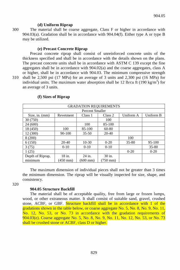
829
(d) Uniform Riprap The material shall be coarse aggregate, Class F or higher in accordance with 300 904.03(a). Gradation shall be in accordance with 904.04(f). Either type A or type B may be utilized. (e) Precast Concrete Riprap Precast concrete riprap shall consist of unreinforced concrete units of the thickness specified and shall be in accordance with the details shown on the plans. The precast concrete units shall be in accordance with ASTM C 139 except the fine aggregates shall be in accordance with 904.02(a) and the coarse aggregates, class A or higher, shall be in accordance with 904.03. The minimum compressive strength shall be 2,500 psi (17 MPa) for an average of 3 units and 2,300 psi (16 MPa) for 310 individual units. The maximum water absorption shall be 12 lb/cu ft (190 kg/m3) for an average of 3 units. (f) Sizes of Riprap
GRADATION REQUIREMENTS Percent Smaller
Size, in. (mm) Revetment Class 1 Class 2 Uniform A Uniform B 30 (750) 100 24 (600) 100 85-100 18 (450) 100 85-100 60-80 12 (300) 90-100 35-50 20-40 8 (200) 100 6 (150) 20-40 10-30 0-20 35-80 95-100 3 (75) 0-10 0-10 0-10 35-80 1 (25) 0-20 0-20 Depth of Riprap, minimum
18 in. (450 mm)
24 in. (600 mm)
30 in. (750 mm)
The maximum dimension of individual pieces shall not be greater than 3 times the minimum dimension. The riprap will be visually inspected for size, shape, and consistency. 320 904.05 Structure Backfill The material shall be of acceptable quality, free from large or frozen lumps, wood, or other extraneous matter. It shall consist of suitable sand, gravel, crushed stone, ACBF, or GBF. Structure backfill shall be in accordance with 1 of the gradations shown in the table below, or coarse aggregate No. 5, No. 8, No. 9, No. 11, No. 12, No. 53, or No. 73 in accordance with the gradation requirements of 904.03(e). Coarse aggregate No. 5, No. 8, No. 9, No. 11, No. 12, No. 53, or No. 73 shall be crushed stone or ACBF, class D or higher.
904.05
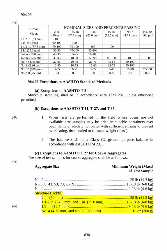
830
330 Sieve Sizes
NOMINAL SIZES AND PERCENTS PASSING 2 in.
(50 mm) 1 1/2 in.
(37.5 mm) 1 in.
(25.0 mm) 1/2 in.
(12.5 mm) No. 4
(4.75 mm) No. 30
(600 µm) 2 1/2 in. (63 mm) 100 2 in. (50 mm) 90-100 100 1 1/2 in. (37.5 mm) 70-100 90-100 100 100 1 in. (25.0 mm) 55-95 70-100 85-100 3/4 in. (19.0 mm) 45-90 55-95 70-100 1/2 in. (12.5 mm) 35-85 40-90 55-95 85-100 100 100 No. 4 (4.75 mm) 20-65 20-70 25-75 45-85 90-100 No. 8 (2.36 mm) 10-50 10-55 15-60 25-75 75-100 No. 30 (600 µm) 3-35 3-35 3-35 5-45 15-70 70-100 No 200 (75 µm) 0-8 0-8 0-8 0-8 0-8 0-8 904.06 Exceptions to AASHTO Standard Methods (a) Exceptions to AASHTO T 2 Stockpile sampling shall be in accordance with ITM 207, unless otherwise permitted. (b) Exceptions to AASHTO T 11, T 27, and T 37 1. When tests are performed in the field where ovens are not 340
available, test samples may be dried in suitable containers over open flame or electric hot plates with sufficient stirring to prevent overheating, then cooled to constant weight (mass).
2. The balance shall be a Class G2 general purpose balance in
accordance with AASHTO M 231. (c) Exceptions to AASHTO T 27 for Coarse Aggregates The size of test samples for coarse aggregate shall be as follows: 350 Aggregate Size Minimum Weight (Mass)
of Test Sample No. 2 ........................................................................................ 25 lb (11.3 kg) No 5, 8, 43, 53, 73, and 91 .................................................. 13-18 lb (6-8 kg) No. 9 ...................................................................................... 9-13 lb (4-6 kg) Structure Backfill 2 in. (50 mm) .................................................................... 25 lb (11.3 kg) 1 1/2 in. (37.5 mm) and 1 in. (25.0 mm) ....................... 13-18 lb (6-8 kg) 1/2 in. (12.5 mm) ............................................................ 9-13 lb (4-6 kg) 360 No. 4 (4.75 mm) and No. 30 (600 µm) ............................... 10 oz (300 g)
904.06
831
(d) Exceptions to AASHTO T 85 The in-water weight (mass) shall be determined following the 15 h soaking period prior to determining the SSD weight (mass). (e) Exceptions to AASHTO T 103 and 104 1. Counting the number of individual particles coarser than the 3/4 in.
(19.0 mm) sieve will not be required. 370 2. For testing ledge rock, the ledge samples shall be crushed to obtain
test samples for the designated increments passing the 1 1/2 in. (37.5 mm) sieve and retained on the No. 4 (4.75 mm) sieve. The factors used to calculate the weighted average loss are 30%, 40%, and 30% of the 1 1/2 in. (37.5 mm) - 3/4 in. (19 mm), 3/4 in. (19.0 mm) - 3/8 in. (9.5 mm), and 3/8 in. (9.5 mm) - No. 4 (4.75 mm) increments, respectively.
3. In the case of ledge rock, modify sections 3.3 and 6.2 of AASHTO 380
T 103 and AASHTO T 104 respectively. When the sample received is deficient in material of a component size of any test portion, that material will be supplemented with the available component size to provide the test portion.
4. Modify section 8 of AASHTO T 103 and section 10 of AASHTO
T 104. For materials designated as a coarse aggregate, the weighted loss will be calculated considering the material retained on the No. 4 (4.75 mm) sieve as 100% of the sample, and only the total weighted loss reported. In AASHTO T 104 sections 10.1.3.2 390 and 10.1.3.3 shall not apply, and unless otherwise noted only new solution will be used.
SECTION 905 – MASONRY UNITS
905.01 Clay or Shale Brick Brick shall be in accordance with the following specifications. (a) Sewer Brick Sewer brick shall be in accordance with AASHTO M 91, Grade SS. (b) Manhole Brick Manhole brick shall be in accordance with AASHTO M 91, Grade MS. 10 (c) Building Brick Building brick shall be in accordance with AASHTO M 114, Grade SW.
905.01
832
905.02 Concrete Brick Concrete brick intended for use in construction of manholes, catch basins, and similar structures, or as building bricks, shall be in accordance with ASTM C 55, Grade S. 905.03 Concrete Masonry Blocks 20 Concrete masonry blocks may be rectangular or segmented and, when specified, shall have ends shaped to provide interlock at vertical joints. Solid masonry units shall be in accordance with ASTM C 139. Hollow load-bearing masonry units shall be in accordance with ASTM C 90, Grade N-II. 905.04 Precast Concrete Curbing Precast concrete curbing shall consist of precast portland cement concrete curb units constructed to the length, shapes, and other details shown on the plans. These units shall be reinforced with steel reinforcement when shown on the plans. Steel reinforcement shall be in accordance with 910.01. 30 When required for driveways, crossings, closures, or for other reasons a depressed or modified section of curb is indicated, curbing with the required modification shall be furnished. 905.05 Detectable Warning Elements The detectable warning surface in concrete curb ramps shall be constructed using materials from the Departments approved list of Detectable Warning Elements, which is maintained by the Office of Materials Management. An element manufacturer wishing to add a product to the approved list shall comply with 40 Procedure L of ITM 806. (a) Brick detectable warning elements shall consist of clay, shale, or
similarly naturally occurring earthy substance, subjected to heat treatment at elevated temperatures to form bricks or pavers. The dimensions of the element shall be 8 in. in length, 4 in. in width including any spacing lugs. The thickness of the element shall be 2 in., excluding dome height and edge chamfers. The truncated domes on the surface shall be formed integral with the main body of the detectable warning element and be present on the element prior to heat treatment. 50 The size and physical requirements of the elements shall be in accordance with ASTM C 902 for weather and traffic environment classifications Class SX, Type II, respectively. The truncated domes may be ground off to meet the cap thickness requirement for compressive strength testing.
(b) Brick detectable warning elements shall be predominantly red-brown in
color and shall be uniform throughout the element. The color will be determined from the average of 5 color readings for detectable warning elements when measured at the top surface between the raised truncated 60
905.02
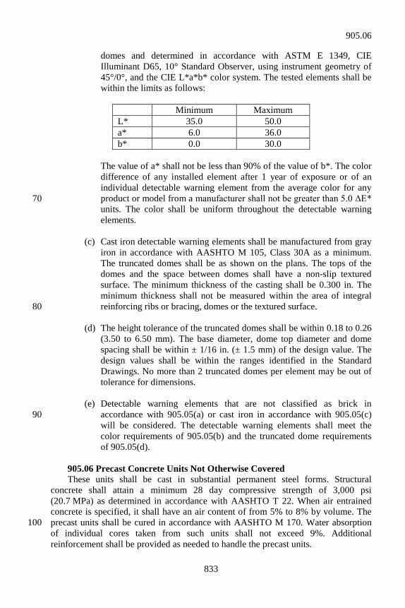
833
domes and determined in accordance with ASTM E 1349, CIE Illuminant D65, 10° Standard Observer, using instrument geometry of 45°/0°, and the CIE L*a*b* color system. The tested elements shall be within the limits as follows:
Minimum Maximum L* 35.0 50.0 a* 6.0 36.0 b* 0.0 30.0
The value of a* shall not be less than 90% of the value of b*. The color
difference of any installed element after 1 year of exposure or of an individual detectable warning element from the average color for any product or model from a manufacturer shall not be greater than 5.0 ΔE* 70 units. The color shall be uniform throughout the detectable warning elements.
(c) Cast iron detectable warning elements shall be manufactured from gray
iron in accordance with AASHTO M 105, Class 30A as a minimum. The truncated domes shall be as shown on the plans. The tops of the domes and the space between domes shall have a non-slip textured surface. The minimum thickness of the casting shall be 0.300 in. The minimum thickness shall not be measured within the area of integral reinforcing ribs or bracing, domes or the textured surface. 80
(d) The height tolerance of the truncated domes shall be within 0.18 to 0.26
(3.50 to 6.50 mm). The base diameter, dome top diameter and dome spacing shall be within ± 1/16 in. (± 1.5 mm) of the design value. The design values shall be within the ranges identified in the Standard Drawings. No more than 2 truncated domes per element may be out of tolerance for dimensions.
(e) Detectable warning elements that are not classified as brick in
accordance with 905.05(a) or cast iron in accordance with 905.05(c) 90 will be considered. The detectable warning elements shall meet the color requirements of 905.05(b) and the truncated dome requirements of 905.05(d).
905.06 Precast Concrete Units Not Otherwise Covered These units shall be cast in substantial permanent steel forms. Structural concrete shall attain a minimum 28 day compressive strength of 3,000 psi (20.7 MPa) as determined in accordance with AASHTO T 22. When air entrained concrete is specified, it shall have an air content of from 5% to 8% by volume. The precast units shall be cured in accordance with AASHTO M 170. Water absorption 100 of individual cores taken from such units shall not exceed 9%. Additional reinforcement shall be provided as needed to handle the precast units.
905.06
834
SECTION 906 – JOINT MATERIALS 906.01 Joint Fillers Joint fillers shall be preformed materials intended to be used in PCCP and bridge joints or as otherwise specified. Joint fillers shall be in accordance with AASHTO M 213. 906.02 Joint Sealing Materials (a) Joint Sealers 10 Joint sealers shall consist of materials which are intended to be used in sealing joints and cracks in pavements and structures. 1. Silicone Joint Sealants a. Physical Requirements Silicone joint sealants shall be in accordance with ASTM D 5893. b. Field Evaluation All silicone joint sealants complying with the physical requirements will be 20 subjected to a field evaluation before approval for general use is granted. The Department will maintain a list of approved Joint Sealant materials, which comply with the physical requirements and field evaluation. c. Specific Requirements for Installation of Silicone Joint Sealant The sealant shall be stored in the original unopened container at or below 90°F (32°C). The sealant shall be placed when the ambient temperature is above 40°F (4°C). The equipment used shall be adequate for the placement of the sealant and shall meet the sealant manufacturer’s recommendations. Air compressors used for 30 the placement of this sealant shall be equipped with traps which remove moisture and oil from the air. The approved sealants which are self leveling shall be identified as such on the Department’s list of approved Joint Sealant materials, and will not require tooling. Sealants not identified as self leveling on the approved list shall be tooled or applied in such a manner which causes them to wet the joint faces. Such sealants which are not formulated for self leveling will not position properly in the joint under its own weight (mass). A backer rod as set out herein shall be used to control sealant configuration and facilitate tooling. Applicable joint configurations shall be as shown 40 on the plans. After a joint has been sealed, all surplus joint sealer on the pavement surfaces shall be promptly removed. Traffic shall not be permitted over sealed joints until the sealer is tack free. The sealant shall be delivered in containers plainly marked with manufacturer’s name or trade mark.
906.01
835
2. Hot Poured Joint Sealant a. General Requirements 50 The sealant shall be in accordance with AASHTO M 324, Type II. The material shall be tested in accordance with ASTM D 5329 except that after blotting, the surface of the blocks shall be blown dry with compressed air. b. Packaging and Marking The sealing compound shall be delivered in the manufacturer’s original sealed container. Each container shall be legibly marked with the name of the manufacturer, the trade name of the sealer, the manufacturing batch number or lot, the pouring temperature, and the safe heating temperature. 60 c. Requirements for Installation The sealant shall be used in accordance with the manufacturer’s recommendations. A backer rod as set out herein shall be used to provide the joint configuration in accordance with the standard drawings. d. Sampling and Testing Samples may be taken prior to delivery provided the plant or warehouse is located in the geographical area serviced by the Department’s inspectors. If not sampled prior to delivery, it will be sampled at the job site. Scheduling shall provide 2 weeks after delivery to the Office of Materials Management for testing. The basis 70 for use will be the applicable laboratory number. 3. Preformed Elastomeric Joint Seals This joint shall be in accordance with AASHTO M 220. Joint seals furnished under this specification shall be covered by a type A certification in accordance with 916.03(b). 4. Polychloroprene Joint Membrane and Adhesive Polychloropene joint membrane shall be general purpose, heavy duty polychloropene sheeting with nylon fabric reinforcement. The sheeting shall be in 80 accordance with the following:
906.02
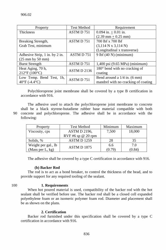
836
Property Test Method Requirement
Thickness ASTM D 751 0.094 in. + 0.01 in. (2.39 mm + 0.25 mm)
Breaking Strength, Grab Test, minimum
ASTM D 751 700 lbf x 700 lbf (3,114 N x 3,114 N) (Longitudinal x transverse)
Adhesive Strip, 1 in. by 2 in. (25 mm by 50 mm)
ASTM D 751 9 lbf (40 N) (minimum)
Burst Strength ASTM D 751 1,400 psi (9.65 MPa) (minimum) Heat Aging, 70 h, 212°F (100°C) ASTM D 2136 180° bend with no cracking of
coating Low Temp. Bend Test, 1h, 40°F (-4.4°C) ASTM D 751 Bend around a 1/4 in. (6 mm)
mandrel with no cracking of coating Polychloroprene joint membrane shall be covered by a type B certification in accordance with 916. The adhesive used to attach the polychloroprene joint membrane to concrete shall be a black styrene-butadiene rubber base material compatible with both concrete and polychloroprene. The adhesive shall be in accordance with the 90 following:
Property Test Method Minimum Maximum Viscosity, cps ASTM D 2196,
RVF #6 sp @ 20 rpm 7,500 18,000
Solids, % ASTM D 1259 28 35 Weight per gal., lb (Mass per L, kg) ASTM D 1875 6.6
(0.79) 7.0
(0.84) The adhesive shall be covered by a type C certification in accordance with 916. (b) Backer Rod The rod is to act as a bond breaker, to control the thickness of the bead, and to provide support for any required tooling of the sealant. 1. Requirements 100 When hot poured material is used, compatibility of the backer rod with the hot sealant shall be verified before use. The backer rod shall be a closed cell expanded polyethylene foam or an isomeric polymer foam rod. Diameter and placement shall be as shown on the plans. 2. Certification Backer rod furnished under this specification shall be covered by a type C certification in accordance with 916.
906.02
837
906.03 Blank 110 906.04 Blank 906.05 Blank 906.06 Blank 906.07 Bridge Expansion Joints Joints, including anchor assemblies, shall be shop fabricated, delivered and installed as a continuous unit for lengths up to 46 ft (14 m). Joints longer than 46 ft 120 (14 m) shall be furnished in continuous units or in appropriate shorter sections as shown on the working drawings and approved by the Engineer. Joints used in stage construction shall be furnished in sections appropriate to accommodate the work. All joints furnished in sections shall be spliced with welds, with ends prepared for welding in the shop. All welds shall be in accordance with 711.32. The profile of the joint in the roadway area shall conform to the roadway cross section. Where changes in direction are required, such as at curbs or concrete rails, the sections shall be cut to the bevel required to produce the same cross section on each piece being joined. Slider plates shall be provided at curbs, walkways, and 130 concrete rails as part of the completed joint assembly. The slider plate shall be the same material as the extrusion and shall be galvanized in accordance with ASTM A 123. All welds in contact with the elastomeric seals shall be ground smooth. Metal surfaces in direct contact with the elastomeric seal shall be cleaned and treated in accordance with the manufacturer’s recommendations to provide a high strength bond between the elastomeric seal and mating metal surfaces. The elastomeric seals shall be clean and free of foreign materials. All exposed structural steel surfaces, except stainless steel or polytetrafluoroethylene coated, shall be shop painted in 140 accordance with 619. (a) Type SS Structural steel shall be in accordance with ASTM A 36 (A 36M), A 588 (A 588M), A 1011 (A 1011M), A 242 (A 242M), or Merchant Quality 1010, 1020. Sealant and grouts shall be in accordance with the manufacturer’s recommendation. The elastomer shall be neoprene in accordance with ASTM D 5973 except that 150 the physical requirements in Table 1 for low temperature recovery, high temperature recovery, and compression-deflection properties will not apply. The strip seal shall be furnished in 1 continuous length for the entire limits of the installed joint. Field splicing of the strip seal will not be permitted. Miter cut,
906.07
838
vulcanized shop splices will be required in the strip seal. The shop vulcanization of the strip seal splice may be either a hot or cold process so long as the process produces a splice of equal or greater strength than the elastomer. The structural steel and polyurethane sealant shall be covered by a type C 160 certification, and the elastomer shall be covered by a type B certification, both in accordance with 916. (b) Type M This joint shall consist of prefabricated multiple elastomeric seals, separator beams, and support bars. The structural design of the joint shall be in accordance with AASHTO LRFD Bridge Construction Specifications and shall be for the same design loading as the bridge structure at which it is to be installed, but not less than HS 20-44 truck loading and impact. The joint shall be designed to accommodate the movement shown on the plans. 170 The joint assembly shall be preset by the manufacturer in accordance with the approved working drawings, joint setting data and specifications. The assembly shall be properly secured for shipping and contain provision for final field adjustment at the time of installation. The manufacturer shall furnish a copy of the installation instructions prior to the placement of these joints. Structural steel shall be in accordance with ASTM A 36 (A 36M), A 1011 (A 1011M), A 242 (A 242M), A 588 (A 588M), or Merchant Quality 1010, 1020 in accordance with ASTM A 576. 180 Sealant and grout shall be in accordance with the joint manufacturer’s recommendation. Elastomer shall be neoprene in accordance with ASTM D 3542. The structural steel and sealant shall be covered by a type C certification and the elastomer by a type B certification, both in accordance with 916. Bearings above and below the support bar shall be a nylon or urethane 190 compound with polytetrafluorethylene riding surfaces. All components of the system shall be accessible to periodic inspection and component replacement if necessary. The elastomer seals shall be in accordance with the requirements as follows: 1. be held in place by compressive forces throughout the normal
limits of joint movement, 2. be supplied and installed in 1 piece; 3. have corner locked edges for a watertight fit; 4. not be any part of the load bearing riding surface; 200
906.07
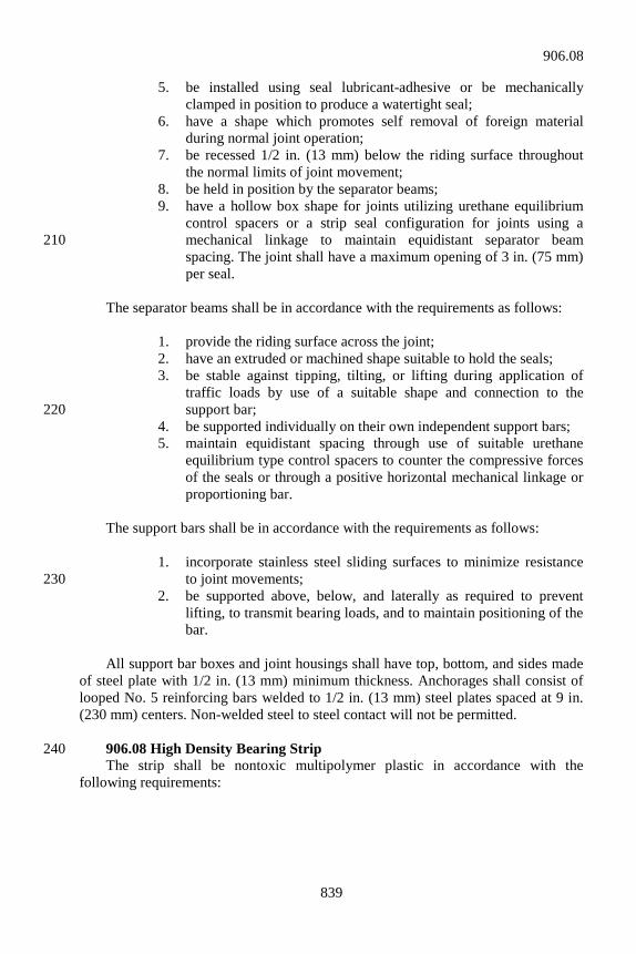
839
5. be installed using seal lubricant-adhesive or be mechanically clamped in position to produce a watertight seal;
6. have a shape which promotes self removal of foreign material during normal joint operation;
7. be recessed 1/2 in. (13 mm) below the riding surface throughout the normal limits of joint movement;
8. be held in position by the separator beams; 9. have a hollow box shape for joints utilizing urethane equilibrium
control spacers or a strip seal configuration for joints using a mechanical linkage to maintain equidistant separator beam 210 spacing. The joint shall have a maximum opening of 3 in. (75 mm) per seal.
The separator beams shall be in accordance with the requirements as follows: 1. provide the riding surface across the joint; 2. have an extruded or machined shape suitable to hold the seals; 3. be stable against tipping, tilting, or lifting during application of
traffic loads by use of a suitable shape and connection to the support bar; 220
4. be supported individually on their own independent support bars; 5. maintain equidistant spacing through use of suitable urethane
equilibrium type control spacers to counter the compressive forces of the seals or through a positive horizontal mechanical linkage or proportioning bar.
The support bars shall be in accordance with the requirements as follows: 1. incorporate stainless steel sliding surfaces to minimize resistance
to joint movements; 230 2. be supported above, below, and laterally as required to prevent
lifting, to transmit bearing loads, and to maintain positioning of the bar.
All support bar boxes and joint housings shall have top, bottom, and sides made of steel plate with 1/2 in. (13 mm) minimum thickness. Anchorages shall consist of looped No. 5 reinforcing bars welded to 1/2 in. (13 mm) steel plates spaced at 9 in. (230 mm) centers. Non-welded steel to steel contact will not be permitted. 906.08 High Density Bearing Strip 240 The strip shall be nontoxic multipolymer plastic in accordance with the following requirements:
906.08
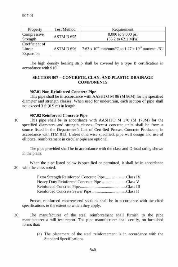
840
Property Test Method Requirement
Compressive Strength ASTM D 695 8,000 to 9,000 psi
(55.2 to 62.1 MPa) Coefficient of Linear Expansion
ASTM D 696 7.62 x 10⁻⁴ mm/mm/ºC to 1.27 x 10⁻³ mm/mm /ºC
The high density bearing strip shall be covered by a type B certification in accordance with 916.
SECTION 907 – CONCRETE, CLAY, AND PLASTIC DRAINAGE COMPONENTS
907.01 Non-Reinforced Concrete Pipe This pipe shall be in accordance with AASHTO M 86 (M 86M) for the specified diameter and strength classes. When used for underdrain, each section of pipe shall not exceed 3 ft (0.9 m) in length. 907.02 Reinforced Concrete Pipe This pipe shall be in accordance with AASHTO M 170 (M 170M) for the 10 specified diameters and strength classes. Precast concrete units shall be from a source listed in the Department’s List of Certified Precast Concrete Producers, in accordance with ITM 813. Unless otherwise specified, pipe wall design and use of elliptical reinforcement in circular pipe are optional. The pipe provided shall be in accordance with the class and D-load rating shown in the plans. When the pipe listed below is specified or permitted, it shall be in accordance with the class noted. 20 Extra Strength Reinforced Concrete Pipe .................... Class IV Heavy Duty Reinforced Concrete Pipe........................ Class V Reinforced Concrete Pipe ............................................ Class III Reinforced Concrete Sewer Pipe ................................. Class II Precast reinforced concrete end sections shall be in accordance with the cited specifications to the extent to which they apply. The manufacturer of the steel reinforcement shall furnish to the pipe 30 manufacturer a mill test report. The pipe manufacturer shall certify, on furnished forms that: (a) The placement of the steel reinforcement is in accordance with the
Standard Specifications.
907.01
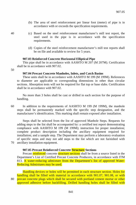
841
(b) The area of steel reinforcement per linear foot (meter) of pipe is in
accordance with or exceeds the specification requirements. (c) Based on the steel reinforcement manufacturer’s mill test report, the 40
steel used in the pipe is in accordance with the specification requirements.
(d) Copies of the steel reinforcement manufacturer’s mill test reports shall
be on file and available to review for 5 years. 907.03 Reinforced Concrete Horizontal Elliptical Pipe This pipe shall be in accordance with AASHTO M 207 (M 207M). Certification shall be in accordance with 907.02. 50 907.04 Precast Concrete Manholes, Inlets, and Catch Basins These units shall be in accordance with AASHTO M 199 (M 199M). References to diameter are applicable to corresponding dimensions in other than circular sections. Absorption tests will not be required for flat top or base slabs. Certification shall be in accordance with 907.02. No more than 3 holes shall be cast or drilled in each section for the purpose of handling. In addition to the requirements of AASHTO M 199 (M 199M), the manhole 60 steps shall be permanently marked with the specific step designation, and the manufacturer’s identification. This marking shall remain exposed after installation. Steps shall be selected from the list of approved Manhole Steps. Requests for adding steps to the list shall be accompanied by: a certified test report demonstrating compliance with AASHTO M 199 (M 199M); instruction for proper installation; complete product description including the ancillary equipment required for installation; and a sample step. The Department may perform a laboratory evaluation of specific steps and may not add steps to the list which are not furnished with ancillary installation equipment. 70 907.05 Precast Reinforced Concrete Structure Sections Precast reinforced concrete structure sections shall be from a source listed in the Department’s List of Certified Precast Concrete Producers, in accordance with ITM 813. A water-reducing admixture from the Department’s list of approved Water-Reducing Admixtures may be used. Handling devices or holes will be permitted in each structure section. Holes for handling shall be filled with material in accordance with 901.07, 901.08, or with precast concrete plugs which shall be secured with portland cement mortar or other 80 approved adhesive before backfilling. Drilled handling holes shall be filled with
907.05
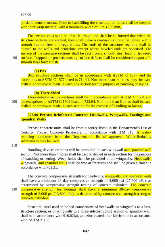
842
portland cement mortar. Prior to backfilling the structure, all holes shall be covered with joint wrap material with a minimum width of 9 in. (225 mm). The section ends shall be of such design and shall be so formed that when the structure sections are erected, they shall make a continuous line of structure with a smooth interior free of irregularities. The ends of the structure sections shall be normal to the walls and centerline, except where beveled ends are specified. The surface of the structure sections shall be cast from a smooth steel form or troweled surface. Trapped air pockets causing surface defects shall be considered as part of a 90 smooth steel form finish. (a) Box Box structure sections shall be in accordance with ASTM C 1577 and the exceptions to ASTM C 1577 listed in 714.04. Not more than 4 holes may be cast, drilled, or otherwise made in each box section for the purpose of handling or laying. (b) Three-Sided Three-sided structure sections shall be in accordance with ASTM C 1504 and the exceptions to ASTM C 1504 listed in 723.04. Not more than 6 holes shall be cast, 100 drilled, or otherwise made in each section for the purpose of handling or laying. 907.06 Precast Reinforced Concrete Headwalls, Wingwalls, Footings and Spandrel Walls Precast concrete units shall be from a source listed in the Department’s List of Certified Precast Concrete Producers, in accordance with ITM 813. A water-reducing admixture from the Department’s list of approved Water-Reducing Admixtures may be used. 110 Handling devices or holes will be permitted in each wingwall and spandrel wall section. Not more than 4 holes shall be cast or drilled in each section for the purpose of handling or setting. Weep holes shall be provided in all wingwalls. Headwalls, wingwalls, and spandrel walls shall be free of fractures and shall be given a finish in accordance with 702.21. The concrete compressive strength for headwalls, wingwalls, and spandrel walls shall have a minimum 28 day compressive strength of 4,000 psi (27,600 kPa), as determined by compressive strength testing of concrete cylinders. The concrete compressive strength for footings shall have a minimum 28-day compressive 120 strength of 2,000 psi (13,800 kPa), as determined by compressive strength testing of concrete cylinders. Structural steel used in bolted connections of headwalls or wingwalls to a box-structure section, or of wingwalls to a three-sided-structure section or spandrel wall, shall be in accordance with 910.02(a), and zinc coated after fabrication in accordance with ASTM A 153.
907.06
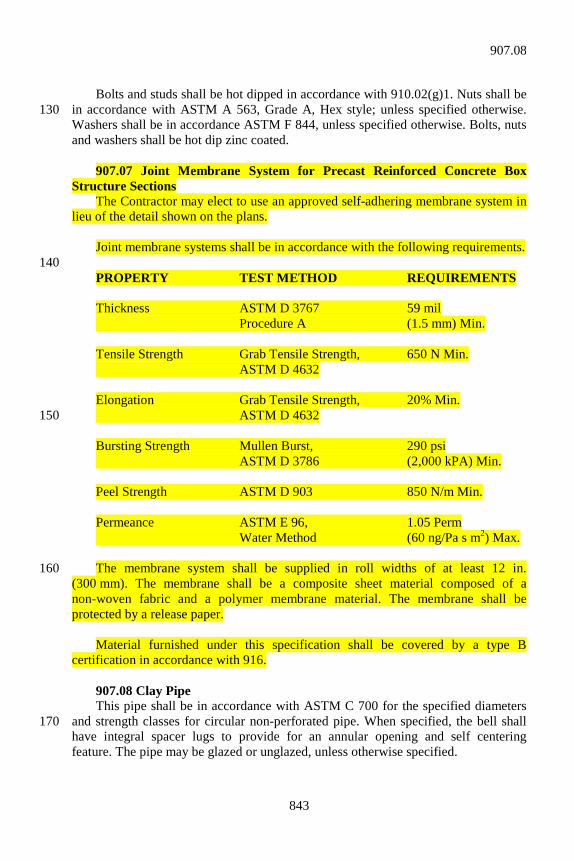
843
Bolts and studs shall be hot dipped in accordance with 910.02(g)1. Nuts shall be in accordance with ASTM A 563, Grade A, Hex style; unless specified otherwise. 130 Washers shall be in accordance ASTM F 844, unless specified otherwise. Bolts, nuts and washers shall be hot dip zinc coated. 907.07 Joint Membrane System for Precast Reinforced Concrete Box Structure Sections The Contractor may elect to use an approved self-adhering membrane system in lieu of the detail shown on the plans. Joint membrane systems shall be in accordance with the following requirements. 140 PROPERTY TEST METHOD REQUIREMENTS Thickness ASTM D 3767 59 mil Procedure A (1.5 mm) Min. Tensile Strength Grab Tensile Strength, 650 N Min. ASTM D 4632 Elongation Grab Tensile Strength, 20% Min. ASTM D 4632 150 Bursting Strength Mullen Burst, 290 psi ASTM D 3786 (2,000 kPA) Min. Peel Strength ASTM D 903 850 N/m Min. Permeance ASTM E 96, 1.05 Perm Water Method (60 ng/Pa s m2) Max. The membrane system shall be supplied in roll widths of at least 12 in. 160 (300 mm). The membrane shall be a composite sheet material composed of a non-woven fabric and a polymer membrane material. The membrane shall be protected by a release paper. Material furnished under this specification shall be covered by a type B certification in accordance with 916. 907.08 Clay Pipe This pipe shall be in accordance with ASTM C 700 for the specified diameters and strength classes for circular non-perforated pipe. When specified, the bell shall 170 have integral spacer lugs to provide for an annular opening and self centering feature. The pipe may be glazed or unglazed, unless otherwise specified.
907.08
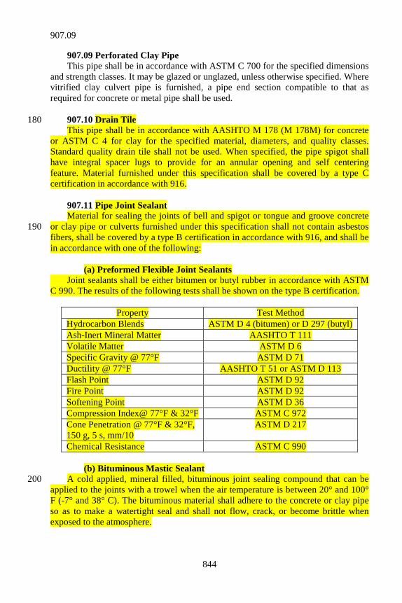
844
907.09 Perforated Clay Pipe This pipe shall be in accordance with ASTM C 700 for the specified dimensions and strength classes. It may be glazed or unglazed, unless otherwise specified. Where vitrified clay culvert pipe is furnished, a pipe end section compatible to that as required for concrete or metal pipe shall be used. 907.10 Drain Tile 180 This pipe shall be in accordance with AASHTO M 178 (M 178M) for concrete or ASTM C 4 for clay for the specified material, diameters, and quality classes. Standard quality drain tile shall not be used. When specified, the pipe spigot shall have integral spacer lugs to provide for an annular opening and self centering feature. Material furnished under this specification shall be covered by a type C certification in accordance with 916. 907.11 Pipe Joint Sealant Material for sealing the joints of bell and spigot or tongue and groove concrete or clay pipe or culverts furnished under this specification shall not contain asbestos 190 fibers, shall be covered by a type B certification in accordance with 916, and shall be in accordance with one of the following: (a) Preformed Flexible Joint Sealants Joint sealants shall be either bitumen or butyl rubber in accordance with ASTM C 990. The results of the following tests shall be shown on the type B certification.
Property Test Method Hydrocarbon Blends ASTM D 4 (bitumen) or D 297 (butyl) Ash-Inert Mineral Matter AASHTO T 111 Volatile Matter ASTM D 6 Specific Gravity @ 77°F ASTM D 71 Ductility @ 77°F AASHTO T 51 or ASTM D 113 Flash Point ASTM D 92 Fire Point ASTM D 92 Softening Point ASTM D 36 Compression Index@ 77°F & 32°F ASTM C 972 Cone Penetration @ 77°F & 32°F, 150 g, 5 s, mm/10
ASTM D 217
Chemical Resistance ASTM C 990 (b) Bituminous Mastic Sealant A cold applied, mineral filled, bituminous joint sealing compound that can be 200 applied to the joints with a trowel when the air temperature is between 20° and 100° F (-7° and 38° C). The bituminous material shall adhere to the concrete or clay pipe so as to make a watertight seal and shall not flow, crack, or become brittle when exposed to the atmosphere.
907.09
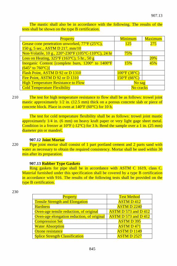
845
The mastic shall also be in accordance with the following. The results of the tests shall be shown on the type B certification.
Property Minimum Maximum Grease cone penetration unworked, 77°F (25°C), 150 g, 5 sec., ASTM D 217, mm/10
125 275
Non-Volatile, 10 g., 220°-230°F (105°C-110°C), 24 hr 75% Loss on Heating, 325°F (163°C), 5 hr., 50 g 20% Inorganic Content [complete burn, 1200° to 1400°F (645° to 760°C)]
15% 45%
Flash Point, ASTM D 92 or D 1310 100°F (38°C) Fire Point, ASTM D 92 or D 1310 150°F (66°C) High Temperature Resistance to Flow No sag Cold Temperature Flexibility No cracks The test for high temperature resistance to flow shall be as follows: trowel joint 210 mastic approximately 1/2 in. (12.5 mm) thick on a porous concrete slab or piece of concrete block. Place in oven at 140°F (60°C) for 10 h. The test for cold temperature flexibility shall be as follows: trowel joint mastic approximately 1/4 in. (6 mm) on heavy kraft paper or very light gage sheet metal. Condition in a freezer at 10°F (-12°C) for 3 h. Bend the sample over a 1 in. (25 mm) diameter pin or mandrel. 907.12 Joint Mortar Pipe joint mortar shall consist of 1 part portland cement and 2 parts sand with 220 water as necessary to obtain the required consistency. Mortar shall be used within 30 min after its preparation. 907.13 Rubber Type Gaskets Ring gaskets for pipe shall be in accordance with ASTM C 1619, class C. Material furnished under this specification shall be covered by a type B certification in accordance with 916. The results of the following tests shall be provided on the type B certification. 230
Property Test Method Tensile Strength and Elongation ASTM D 412 Hardness ASTM D 2240 Oven-age tensile reduction, of original ASTM D 573 and D 412 Oven-age elongation reduction, of original ASTM D 573 and D 412 Compression Set ASTM D 395 Water Absorption ASTM D 471 Ozone resistance ASTM D 1149 Splice Strength Classification ASTM D 2527
907.13
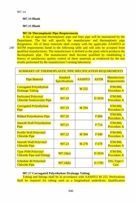
846
907.14 Blank 907.15 Blank 907.16 Thermoplastic Pipe Requirements A list of approved thermoplastic pipe and liner pipe will be maintained by the Department. The list will specify the manufacturer and thermoplastic pipe designation. All of these materials shall comply with the applicable AASHTO or ASTM requirements listed in the following table and will only be accepted from 240 qualified manufacturers. The manufacturer is defined as the plant which produces the thermoplastic pipe. The manufacturer shall become qualified by establishing a history of satisfactory quality control of these materials as evidenced by the test results performed by the manufacturer’s testing laboratory.
SUMMARY OF THERMOPLASTIC PIPE SPECIFICATION REQUIREMENTS
Pipe Material Standard Specifications AASHTO ASTM Manufacturer
Requirements
Corrugated Polyethylene Drainage Tubing 907.17 M 252 ITM 806,
Procedure A
Perforated Polyvinyl Chloride Semicircular Pipe 907.18 D 3034 ITM 806,
Procedure A
Corrugated Polyethylene Pipe 907.19 M 294 ITM 806,
Procedure O
Ribbed Polyethylene Pipe 907.20 F 894 ITM 806, Procedure A
Smooth Wall Polyethylene Pipe 907.21 F 714 ITM 806,
Procedure A
Profile Wall Polyvinyl Chloride Pipe 907.22 M 304 F 949 ITM 806,
Procedure A
Smooth Wall Polyvinyl Chloride Pipe 907.23 M 278 F 679 ITM 806,
Procedure A
Type PSM Polyvinyl Chloride Pipe and Fittings 907.24(a) D 3034 ITM 806,
Procedure A
Schedule 40 Polyvinyl Chloride Pipe 907.24(b) D 1785 916, Type C
Cert. 907.17 Corrugated Polyethylene Drainage Tubing Tubing and fittings shall be in accordance with AASHTO M 252. Perforations shall be required for tubing used as a longitudinal underdrain. Qualification
907.14
847
requirements for the manufacturers shall be in accordance with ITM 806, Procedure 250 A. 907.18 Perforated Polyvinyl Chloride Semicircular Pipe Perforated polyvinyl chloride semicircular pipe may be used as an alternate to 6 in. (150 mm) or less diameter pipe or tile. Pipe shall be in accordance with ASTM D 3034, SDR 35. This semicircular pipe shall have a smooth top and a smooth, semicircular bottom, nominally 4 5/8 in. (118 mm) in diameter, with perforations uniformly distributed along the top of the bottom section in accordance with AASHTO M 252 perforation requirements. The top section shall extend a minimum of 1/2 in. (13 mm) beyond the top of the semicircular section. The top section shall 260 be approximately 6 3/8 in. (162 mm) wide including the sloping overhangs on each side. Qualification requirements for the manufacturers shall be in accordance with ITM 806, Procedure A. 907.19 Corrugated Polyethylene Pipe Pipe and fittings shall be in accordance with AASHTO M 294. Qualification requirements for the manufacturers shall be in accordance with ITM 806, Procedure O. 907.20 Ribbed Polyethylene Pipe 270 Pipe and fittings shall be in accordance with ASTM F 894. Qualification requirements for the manufacturers shall be in accordance with ITM 806, Procedure A. 907.21 Smooth Wall Polyethylene Pipe Pipe shall be in accordance with ASTM F 714 for nominal diameters of 39 in. (1,000 mm) or less. Fittings shall be in accordance with ASTM F 1055. The pipe sizes shall be in accordance with ISO sizing system. The pipe dimension ratio shall be 26 or less. The resin used in manufacturing this type of pipe shall have a minimum cell classification of 335434C in accordance with ASTM D 3350 or a 280 minimum grade of PE4710 in accordance with ASTM F 714. Qualification requirements for the manufacturers shall be in accordance with ITM 806, Procedure A. 907.22 Profile Wall Polyvinyl Chloride Pipe Pipe and fittings shall be in accordance with AASHTO M 304 or ASTM F 949. Perforations shall be required when used as a longitudinal underdrain or end bent drain pipe. Qualification requirements for the manufacturers shall be in accordance with ITM 806, Procedure A. 290 907.23 Smooth Wall Polyvinyl Chloride Pipe Pipe and fittings shall be in accordance with AASHTO M 278 for pipe sizes 4 in. through 15 in. (100 mm through 375 mm), and ASTM F 679 for pipe sizes 18 in. through 27 in. (450 mm through 675 mm). Qualification requirements for the manufacturers shall be in accordance with ITM 806, Procedure A.
907.23
848
907.24 Smooth Wall Pipe for Outlets Pipe and pipe fittings shall be smooth wall, non-perforated plastic pipe. Qualification requirements for the manufacturers shall be in accordance with ITM 806, Procedure A. 300 (a) Type PSM Polyvinyl Chloride Pipe and Fittings Pipe and fittings shall be in accordance with ASTM D 3034, SDR 23.5. (b) Schedule 40 Polyvinyl Chloride Pipe Pipe shall be in accordance with ASTM D 1785 and shall have a minimum pipe stiffness of 150 psi (1,030 kPa) at 5% deflection when determined in accordance with ASTM D 2412. Material furnished under this specification shall be covered by a type C certification in accordance with 916 and shall reference ASTM D 1785 in the product printline. 310 907.25 Thermoplastic Liner Pipe Thermoplastic liner pipe shall be high density polyethylene or polyvinyl chloride pipe with sufficient rigidity to withstand the installation operation and shall exhibit a minimum amount of distortion. The liner pipe shall be free from visible cracks, holes, foreign inclusions, or other defects. (a) Solid Wall HDPE Liner Pipe Solid wall HDPE liner pipe shall be in accordance with ASTM F 714. The maximum standard dimension ratio, SDR, for the liner pipe as defined in ASTM F 320 412 shall be 32.5. The resin used in the manufacture of the liner pipe shall have a minimum cell classification of 345464C in accordance with ASTM D 3350 or a minimum grade of PE4710 in accordance with ASTM F 714. A 12 in. (300 mm) section of the liner pipe shall show no evidence of splitting, cracking, or breaking when compressed between parallel plates to 40% of its outside diameter within 2 to 5 min. Thermoplastic liner pipe may be added to the Department’s approved list by completing the requirements of ITM 806, Procedure Q. (b) Profile Wall HDPE Liner Pipe Profile wall HDPE liner pipe shall be in accordance with ASTM F 894. The 330 minimum liner ring stiffness constant, RSC, shall be 100. Thermoplastic liner pipe may be added to the Department’s approved list by completing the requirements of ITM 806, Procedure A. (c) Profile Wall PVC Liner Pipe Profile wall PVC liner pipe shall be in accordance with ASTM F 949. Thermoplastic liner pipe may be added to the Department’s approved list by completing the requirements of ITM 806, Procedure A.
907.24
849
907.26 Solvent Cements for Polyvinyl Chloride Pipe and Pipe Fittings 340 Solvent cement for polyvinyl chloride pipe and fittings shall be in accordance with ASTM D 2564. Material furnished under this specification shall be covered by a type C certification in accordance with 916. 907.27 Elastomeric Seals Elastomeric seals for joining plastic pipe shall be in accordance with ASTM F 477. Material furnished under this specification shall be covered by a type B certification in accordance with 916. The results of the following tests shall be provided on the type B certification. 350
Test ASTM Tensile Strength D 412 or D 1414 Ultimate Elongation D 412 or D 1414 100% Modulus D 412 or D 1414 Hardness (Durometer) D 2240 or D 1414 Low-Temperature Hardness D 2240 or D 1414 Compression Set D 395 Method B, or D 1414 Accelerated Aging D 573 Water Immersion D 471 Ozone Resistance D 1149 Elastomer Compound Effect on Pipe F 477 Force Decay (Stress Relaxation) F 913
907.28 Reinforced Thermosetting Resin Pipe and Pipe Fittings Reinforced thermosetting resin pipe and accompanying fittings shall be in accordance with ASTM D 2996 for the specified sizes. The short-term rupture strength hoop tensile stress shall be a minimum of 30,000 psi (207 MPa). All pipes shall be pigmented resin throughout the wall thickness. The color of the pipe shall be gray. Painting, gel-coating, or exterior coating of the pipe to obtain the specified color shall not be done. Material furnished shall be covered by a type A certification in accordance with 916. The results of the following tests shall be provided on the type A certification. 360
Test ASTM Wall Thickness & Diameter D 3567 Short-Term Hydrostatic Failure Strength D 1599 Longitudinal Tensile Properties D 2105 or D 638 Stiffness Factor D 2412, based on 5% deflection
907.28
850
SECTION 908 – METAL PIPE 908.01 Blank 908.02 Corrugated Steel Pipe and Pipe-Arches Corrugated steel pipe and pipe-arches shall be type I, IA, II, or IIA in accordance with AASHTO M 36 (M 36M). Corrugated steel pipe, pipe-arches, and coupling bands shall be zinc coated steel or aluminum coated steel in accordance with AASHTO M 36 (M 36M), except as 10 noted herein. They may be fabricated with circumferential corrugations and riveted lap joint construction or with helical corrugations with continuous lock or welded seam extending from end to end of each length of pipe. Reforming the ends of helical corrugated pipe to form circumferential corrugations will be permitted to allow use of circumferential corrugated coupling bands. The reforming shall be limited to the length required to accommodate the coupling bands and in such a manner that there is not appreciable slippage of the seam nor a plane of weakness created. Polymer precoated galvanized corrugated steel pipe type IA and pipe-arch type 20 IIA have an outer shell of corrugated sheet with helical corrugations and an inner liner of smooth sheet attached to the shell with a helical lock seam. Fittings, including stub-tee connections and saddle connectors specified in 715.06, shall be shop fabricated. Damage to the coating on fittings shall be repaired in accordance with AASHTO M 36. If the pipe or pipe-arch invert is to be paved, it shall 1st be coated over half its circumference in accordance with 908.07. The paved invert shall then be constructed in accordance with 908.07. 30 Sheet metal used to fabricate pipe shall be the same brand from the same manufacturer in any 1 length of finished pipe. The manufacturer shall furnish to the fabricator a certified mill report for materials shipped to the fabricator. This certified mill report shall list the kind of base metal, actual test results of the chemical analysis and mechanical tests of each heat, the thickness, the weight (mass) of coating, and shall certify that the material complies with specified requirements for the type of metal furnished. 40 The fabricator shall certify, on furnished forms that: (a) the fabricated structure has been manufactured in accordance with these
Standard Specifications;
908.01
851
(b) based on the sheet manufacturer’s certified mill report, the materials used in fabricating the structure were tested and the test results are in accordance with the specified requirements; and
(c) copies of the sheet manufacturer’s certified mill report shall be on file 50
and available to review for 5 years. 908.03 Blank 908.04 Corrugated Aluminum Alloy Pipe and Pipe-Arches Pipes, pipe-arches, and coupling bands shall be in accordance with AASHTO M 196 (M 196M). The pipe shall be type I, IA, II, or IIA. If the pipe invert is to be paved, it shall be in accordance with 908.07. The sheet manufacturer’s certified mill report and the fabricator’s certification 60 shall be in accordance with 908.02, except the documents shall be in accordance with the applicable requirements of AASHTO M 196 (M 196M). Where aluminum alloy pipe culvert is furnished, aluminum alloy end sections shall also be furnished. All component parts shall be aluminum alloy. 908.05 Blank 908.06 Metal End Sections The end section’s metal shall be in accordance with AASHTO M 36 (M 36M) or 70 M 196 (M 196M), whichever is applicable. The sheet metal manufacturer’s certified mill report and the fabricator’s certification shall be in accordance with 908.02 or 908.04, whichever is applicable. End sections consisting of multiple panels shall have lap seams which shall be tightly jointed with 3/8 in. (M10) galvanized rivets or bolts. All steel pipe end sections shall have a toe plate anchor constructed of 0.138 in. (3.5 mm) thick galvanized steel. The toe plate anchor shall be match punched to fit holes in the skirt lip, and shall be supplied loose, and complete with 3/8 in. (M10) 80 diameter galvanized bolts. Straps for pipe end sections shall be either galvanized No. 6 (20M) reinforcing bars or zinc coated 3/8 in. (10 mm) diameter aircraft cable. 908.07 Fully Bituminous Coated Corrugated and Lined Steel Pipe and Pipe-Arches The material, fabrication, the manufacturer’s certified mill report, and fabricator’s certification shall be in accordance with the applicable requirements of 908.02. Coupling bands shall be fully bituminous coated. 90
908.07
852
After fabrication, the pipe or pipe-arch shall be fully bituminous coated. Connecting or coupling bands shall be of the 2-piece type when used with coated pipe of 36 in. (900 mm) diameter or larger. The asphalt material for coating shall be in accordance with 902.01(e). Samples of the asphalt material will be obtained from the working tank prior to or during coating of the pipe, or from strippings off the pipe after coating. When applied to the pipe, the asphalt material shall be free from impurities. The metal shall be free from 100 grease, dust, or moisture. Either process set out below may be used for application. (a) When the pipe is not preheated, the temperature of the asphalt at the
time of immersion shall be 400°F ± 5°F (204°C ± 3°C). The duration of the immersion in the asphalt shall be in accordance with the following:
Thickness 0.052 in.
(1.32 mm) 0.064 in.
(1.63 mm) 0.079 in.
(2.01 mm) 0.109 in.
(2.77 mm) 0.138 in.
(3.51 mm) 0.168 in.
(4.27 mm) Minimum Immersion Time for 1st Dip (min)
2.0
2.5
3.0
5.0
6.5
8.0 (b) When the pipe is preheated it shall be brought to a temperature of
300°F (149°C) and the asphalt shall be heated to a temperature of 380°F ± 5°F (193°C ± 3°C) before the pipe is dipped. 110
In either process, the pipe shall be dipped a 2nd time or more if necessary, to give a minimum thickness of 0.05 in. (1.3 mm). If paved invert is specified, the pipe or pipe-arch shall 1st be fully coated as required. Additional bituminous material shall be applied in the bottom section to form a smooth pavement. Except where the upper edges intersect the corrugations, the pavement shall have a minimum thickness of 1/8 in. (3 mm) above the crests of the corrugations. The pavement shall be applied to the lower quarter of the circumference. 120 The manufacturer of the asphalt material shall furnish to the pipe fabricator the type of certification specified in the Frequency Manual and in accordance with 916 for each shipment or lot of asphalt material. The pipe fabricator shall keep these certifications on file and available to review for 5 years. In addition, samples from the working tank will be obtained for verification of requirements. 908.08 Polymer Precoated Galvanized Corrugated Steel Culvert Pipe and Pipe-Arches The pipe or pipe-arch and coupling bands shall be in accordance with AASHTO 130 M 245 (M 245M) with additions in accordance with 908.02. The polymer precoated galvanized steel sheets shall be in accordance with AASHTO M 246 (M 246M), Grade 10/10 (250/250).
908.08
853
908.09 Structural Plate Pipe, Pipe-Arches, and Arches (a) Steel Steel structural plate pipe, pipe-arches, and arches shall be constructed from individually galvanized corrugated steel plates as described herein. For pipes and pipe-arches having a thickness less than 0.280 in. (7.11 mm), the bottom plates shall 140 be of the next greater thickness than that specified for the top and side plates, not including corner plates for pipe-arches. The individual plates shall be in accordance with AASHTO M 167 (M 167M) and AASHTO LRFD Bridge Construction Specifications. The materials and fabrication shall be as follows: 1. The minimum corner plate radius of the arc joining the top and
bottom plates of pipe-arches shall be 18 in. (457 mm) for openings up to and including 131 sq ft (12.2 m2) and 31 in. (787 mm) for 150 openings over 131 sq ft (12.2 m2). The minimum radius of the arc shall be 31 in. (787 mm) for openings from 98 sq ft (9.1 m2) up to and including 214 sq ft (19.8 m2).
2. Assembly bolts shall be in accordance with AASHTO M 164
(M 164M), ASTM A 325 (A 325M), or ASTM A 449. Nuts shall be in accordance with ASTM A 563 (A 563M), grade C (class 8S); AASTHO M 164 (M 164M); or ASTM A 325 (A 325M). Assembly bolts, nuts, and washers shall be galvanized in accordance with ASTM A 153, or be mechanically galvanized and 160 conform to the coating thickness, adherence, and quality requirements of ASTM A 153, class C.
3. The sheet manufacturer’s certified mill report and the fabricator’s
certification shall be furnished in accordance with 908.02, except the documents shall be in accordance with the applicable requirements of AASHTO M 167 (M 167M).
(b) Aluminum Alloy Aluminum alloy structural plate pipe, pipe-arches, and arches shall be in 170 accordance with AASHTO M 219 (M 219M). The sheet manufacturer’s certified mill report and the fabricator’s certification shall be furnished in accordance with 908.02. 908.10 Cast Iron Soil Pipe This pipe shall be in accordance with ASTM A 74. Markings shall be in accordance with ASTM A 74 or ANSI A 40.1.
908.10
854
908.11 Steel Pipe This item shall be electric-fusion, arc-welded steel pipe in accordance with 180 ASTM A 139, grade B, or electric-resistance welded pipe in accordance with ASTM A 53, Type E, Grade B, as applicable. Material furnished under this specification shall be covered by a type C certification in accordance with 916. 908.12 Straps, Hook Bolts and Nuts Used in Anchors Straps shall be of the type and size shown on the plans. Reinforcing bars used for straps shall meet the applicable requirements of 910.01 and shall be galvanized in accordance with ASTM A 767 (A 767M), class I. Aircraft cable used for straps shall be made of zinc coated steel wire, 3/8 in. (9.5 mm) nominal diameter, consisting of seven 19 wire flexible steel strands, with a minimum breaking strength of 14,000 lb 190 (62.3 kN). The cable shall be in accordance with Military Specification MIL-W-83420D. Hook bolts and nuts shall be of the size shown on the plans, shall be in accordance with ASTM A 307, and shall be galvanized in accordance with ASTM A 153. Threads shall be American Standard Coarse Thread Series Class 2 fit. Threads shall be cleaned after galvanizing to provide a free running fit. Maximum oversizing of the nut threads shall be 1/64 in. (0.4 mm). 908.13 Blank 200 908.14 Slotted Drain or Slotted Vane Drain Pipe Slotted drains shall be manufactured from helically corrugated steel pipe in accordance with AASHTO M 36 (M 36M). At the end of the pipe there shall be 2 annular corrugations to permit the corrugated band to fully mesh with the pipe. The grated assembly shall be made of structural steel in accordance with AASHTO M 183 (M 183M), Grade 36. The assembly shall be suitably welded to the pipe and galvanized after assembly in accordance with AASHTO M 111. The grate shall be of the size and spacing shown on the plans and shall be welded on both sides 210 to each bearing bar with a 3/16 in. (5 mm) fillet weld. The size and thickness of the corrugated steel slotted drain pipe shall be as shown on the plans. Slotted vane drain pipe shall be smooth wall polyvinyl chloride in accordance with 907.23, and shall be of the diameter specified. The casting shall be in accordance with 910.05(b). The finish shall be standard black asphalt emulsion. Individual units shall have a minimum weight (mass) of 155 lb (70 kg).
908.11
855
SECTION 909 – PAINT AND LIQUID EPOXY 909.01 General Requirements All necessary facilities for inspection of materials and manufacture of coatings, paints, and ingredients shall be granted. Free access to all parts of the premises where any or all of these products are being prepared shall be allowed. Material Safety Data Sheets shall be provided. Paints and coatings shall be furnished ready for use without modification and shall not settle, cake, curdle, liver, gel, or develop excessive change in viscosity 10 between time of manufacture and time of use. It shall remain capable of being readily dispersed with a paddle, or other approved methods, to a consistency appropriate for the intended use. Paints and coatings may be sampled and tested at any time prior to use. If, for any reason, re-sampling and re-testing following initial or prior approval is indicated, the latest test results shall prevail over all previous tests for material that has not been used. Previously approved paint or coating that are stored for future use may be re-sampled and re-tested. Paints and coatings shall be delivered in new containers of such strength, durability, design, fabrication, and material that the paint shall be suitably protected 20 in transit and in storage against any change in characteristics which would cause rejection on the basis of laboratory or field evaluation. Each container shall bear a label which shows the name and address of the manufacturer, kind of paint or coating, formula identification, date of manufacture, and lot or batch number. The weight per gallon (mass per volume) lb per gal. (kg/L) of the paint shall be accurately determined at 77°F (25°C). The container shall be so filled that the net weight (mass) of the material in the container shall be the product of the weight per gallon (mass per volume) at 77°F (25°C) and the stated number of gallons (liters) in the container. 30 All containers shall be labeled in accordance with the OSHA requirements for labeling of hazardous chemicals as described in the Hazardous Communications Standard. 909.02 For Metal Paints for metal surfaces shall be in accordance with the requirements shown below. (a) Zinc Primers 40 1. Multi-Component Inorganic Zinc Silicate Primer These primers shall be of the self-cure type which, when mixed and applied in accordance with these specifications, shall cure without the use of a separate curing solution. The multi-component inorganic zinc silicate primers shall have a maximum of 3 components. The components of each primer shall be packaged in such
909.02
856
proportions that when the full quantity of each component is mixed together, the specified mixed primer shall be yielded. These inorganic primers shall be in accordance with AASHTO M 300. 50 Inorganic zinc primer for use on faying surfaces at all slip-critical structural bolted connections using ASTM A 325 or ASTM A 490 high-strength bolts in primary members shall meet class B slip coefficient in accordance with Test Method to Determine the Slip Coefficient for Coatings Used in Bolted Joints as adopted by the Research Council on Structural Connections. 2. Organic Zinc Primer Organic zinc primer shall be a self-curing type primer. It shall be in accordance with SSPC paint specification No. 20 type II with exceptions as follows. 60 Table I, total zinc dust, percent by weight (mass) of pigment requirement shall be a minimum of 84% metallic zinc. Table I, total zinc dust, percent by weight (mass) of total solids requirement shall be a minimum of 72% metallic zinc. The viscosity variation in Kreb Units in Section 6.2 shall be ± 10. The organic zinc primer shall also be in accordance with the requirements as follows. a. The viscosity shall be 70 to 100 Kreb units. 70 b. The weight per gallon (mass per volume) shall be a minimum
of 17.0 lb/gal. (2.04 kg/L). c. The dry time shall be a maximum of 1 h set-to-touch and 24 h
dry hard when applied at 6 mil (150 µm) blade clearance to a tin coated steel panel at 25°C and 60% ± 5% relative humidity.
d. The infrared spectrum of the vehicle shall match the infrared
spectrum of the vehicle of the sample submitted for formulation approval. 80
e. The organic zinc primer shall not exceed 3.5 lb/gal.
(0.419 kg/L) volatile organic compounds. The cured film shall not contain toxic heavy metals above the regulatory levels of 40 CFR 261.24.
f. The organic zinc primer shall be compatible with inorganic
zinc and finish coat paints already on the bridge. The color shall be able to produce a distinct contract with blast cleaned metal surface and the finish coat. The cured organic zinc film 90
909.02
857
shall be compatible with a top coating of waterborne finish coat paint.
Organic zinc primer for use on faying surfaces at all slip-critical structural bolted connections using ASTM A 325 or ASTM A 490 high-strength bolts in primary members shall meet class B slip coefficient in accordance with Test Method to Determine the Slip Coefficient for Coatings Used in Bolted Joints as adopted by the Research Council on Structural Connections. 3. Approval of Formulation 100 The manufacturer shall obtain approval of the formulation prior to furnishing the primers. Only zinc primers from the Department’s list of approved Coating Formulations shall be used. Zinc primers will be placed and maintained on the Department’s list of approved Coating Formulations in accordance with ITM 606. (b) Epoxy Intermediate Paint Epoxy intermediate paint shall be a 2 component coating consisting of an epoxy resin and a curing agent, together with prime and filler pigments, colorants, gellant, leveling agents and solvents. When mixed, this coating shall be suitable for application over inorganic and organic zinc primers and shall be compatible with a 110 polyurethane finish coat. The color of this coating shall contrast significantly from the other coatings within the coating system. The mixed paint shall be in accordance with the requirements as follows. Volatile organic compounds, ASTM D 3960, Max. ........................... 336 g/L Volume solids, ASTM D 2697, Min. ...................................................... 60% Set-to-touch, ASTM D 1640, 6 mils (150 µm) wet film thickness, 25 ± 1°C, Max. .................................................................................... 4 h Potlife, 25 ± 1°C, Min. ............................................................................... 6 h 120 Weight (mass)/volume variance from the initially approved batch, ASTM D 1475, 25°C, Max. ......................................... 0.060 kg/L Total solids variance from the initially approved batch, ASTM D 2369, Max. ....................................................................... 3.0% The infrared spectra of each component and of the mixed coating shall essentially match the spectrums of the initially approved batch. (c) Polyurethane Finish Coat Polyurethane finish coat shall be a 2 component polyester or acrylic aliphatic 130 polyurethane suitable for use as a finish coat over epoxy intermediate paint. The mixed paint shall be in accordance with the requirements as follows. Volatile organic compounds, ASTM D 3960, Max. ........................... 336 g/L Volume solids, ASTM D 2697, Min. ...................................................... 60%
909.02
858
Set-to-touch, ASTM D 1640, 5 mils (127 µm) wet film thickness, 25 ± 1°C, 50 ± 10% relative humidity, Min. .................................30 min Total solids ASTM D 2369, Min. ............................................................ 70% Specular gloss, 60°, ASTM D 523, Min. ..................................................... 75 140 Viscosity, ASTM D 562, Kreb Units, Max. .............................................. 100 Contrast ratio, ASTM D 2805, 5 ± 0.5 mils (127 ± 13 µm) wet film thickness, dried 24 h @ 25 ± 2°C on Leneta Form 2A or 2C, Min. ........................................................................................ 0.95 Dry hard, ASTM D 1640, 5 mils (127 µm) wet film thickness, 25 ± 1°C, 50 ± 10% relative humidity, Max. ..................................... 24 h The infrared spectra of each component and of the mixed coating shall essentially match the sprectrums of the initially approved batch. 150 The color of the dried paint film shall match the color number of Federal Standard 595 as follows.
Color No. Color 14260 Green 15450 Light Blue 17886 White 13538 Yellow 13711 Buff 17038 Black
(d) Waterborne Finish Paint The waterborne finish coating shall be a single package, high build acrylic emulsion for use as a finish coat over inorganic and organic zinc primers. It shall be compatible with and adhere to the cured zinc primers. 1. Vehicle Component 160 The vehicle shall consist of an acrylic emulsion together with the necessary antifoamers, cosolvents, coalescing agent, preservatives, and antifreeze in order to produce a coating in accordance with this specification. 2. Pigment Component The active pigment shall consist of titanium dioxide in accordance with ASTM D 476, type IV, and non-reactive color retentive tinting pigments. The pigment shall contain extenders and additives as required for proper application. 3. Mixed Paint Properties 170 The mixed paint shall be in accordance with the requirements as follows: Viscosity, ASTM D 562, Kreb Units................................................. 80 – 100 Weight (mass)/volume, ASTM D 1475, deviation from approval formulation, Max. ................................. 0.2 lb/gal. (0.024 kg/L)
909.02
859
Pigment grind, ASTM D 1210, Hegman, Min. ............................................. 5 Total solids, % by weight (mass), ASTM D 2369, Min. ............................. 48 Vehicle solids, % of vehicle by weight (mass), Min. ............................... 37.5 Dry time, ASTM D 1640, 3 mils (75 µm) wet film thickness on a tin coated steel panel @ 25 ± 1°C and 50 ± 5% relative humidity, Max: 180 Set-to-touch, h ................................................................................. 1 Dry hard, h .................................................................................... 24 Contrast ratio, ASTM D 2805, 5 ± 0.5 mils (125 ± 13 µm) wet film thickness dried 24 h @ 25 ± 2°C on Leneta Form 2A or 2C, Min. ......................................................................... 0.97 Specular gloss, 60°, 10 mils ± 0.5 mils (250 ± 13 µm) wet film thickness on a tin coated steel panel, dried 48 h @ 25°C and 50 ± 5% relative humidity, ASTM D 523, Max. .............................................................. 30 pH, ASTM E 70 ................................................................................. 7.0 – 9.0 Volatile organic compounds, ASTM D 3960, 190 Max. ................................................................... 1.50 lb/gal. (0.180 kg/L) The infrared spectrum of the vehicle when extracted from the mixed paint in accordance with ASTM D 3168 shall match the infrared spectrum of the sample submitted for formulation approval. The mixed paint shall be in accordance with the requirements of Sections 5.4 through 5.17 of SSPC paint specification No. 24. The cured waterborne finish paint shall not contain toxic heavy metals above the 200 regulatory levels of 40 CFR 261.24. 4. Color The color of the dried paint film shall match the color number of Federal Standard 595 as follows.
Color No. Color 24227 Green 24466 Light Green 25526 Light Blue 27780 White 23538 Yellow 23717 Buff 27038 Black
5. Approval of Formulation The manufacturer shall obtain approval of the formulation prior to furnishing the waterborne finish paint. Only waterborne finish paint from the Department’s list of 210 approved Coating Formulations shall be used. Waterborne finish paint formulations will be placed and maintained on the list of approved Coating Formulations in accordance with ITM 606.
909.02
860
(e) Finish Coat for Weathering Steel The finish coat shall be an aliphatic polyurethane or a waterborne acrylic paint. It shall be suitable for use as a finish coat over epoxy intermediate paint. The mixed paint shall be in accordance with the requirements as follows. Specular gloss, 60°, ASTM D 523, Max. ................................................. 25.0 220 Weight (mass)/volume variance from the initially approved batch, ASTM D 1475, 25°C, Max. ......................................... 0.048 kg/L Total solids variance from the initially approved batch, ASTM D 2369, Max. ............................................................ 2.0% Volatile Organic Compounds, ASTM D 3960, Max. ......................... 336 g/L The dried paint film shall match color number 20045 of Federal Standard 595. 909.03 Structural Steel Coating System This coating system shall consist of an inorganic zinc primer, an epoxy 230 intermediate paint, and a polyurethane finish coat for the painting of steel bridges and other structural steel. All of the coatings within any coating system shall be manufactured by the same manufacturer and shall be compatible with 1 another. All coatings shall be in accordance with 909.02. (a) Toxicity The cured film of each coating within the structural steel coating system shall not contain any toxic heavy metals above the limits of the regulatory levels of 40 CFR 261.24, table 1, when tested in accordance with EPA TCLP, or contain any other material which will require characterization as a hazardous waste for the 240 disposal of the dried film. (b) Resistance The coating system shall be tested in accordance with the requirements of NEPCOAT, Specification Criteria For Protective Coatings, dated June 6, 1996. The coating system shall be in accordance with all of the acceptance criteria and shall maintain a specular gloss retention of 60% relative of the initial gloss and a maximum color change of 15 ΔE for Test No. 3, Weathering Resistance. (c) Approval of Structural Steel Coating System 250 The manufacturer shall obtain approval of each structural steel coating system prior to furnishing any of these coatings. Only structural steel coating systems from the Department’s list of approved Structural Steel Coating Systems shall be used. Structural steel coating systems will be placed and maintained on the Department’s list of approved Structural Steel Coating Systems in accordance with ITM 606. 909.04 Field Paint for Wood or Metal The primers for field paint shall be formulated for minimal surface preparation, provide adhesion to the substrate and be compatible with the finish coat. The primers
909.03
861
shall not contain lead, chromium, or other heavy metals which would require 260 classification as a hazardous waste upon removal. The primers shall comply with the current IDEM VOC regulations and shall be used as follows. a. For unpainted galvanized steel and other ferrous metals, use 1
coat of a zinc dust-zinc oxide pigmented primer. b. For non-ferrous metals, use 1 coat of primer formulated for use
on non-ferrous metals. The field paint finish coat shall be an exterior type coating. It shall be chalk 270 resistant, gloss retentive, and suitable for application by brush, roller, or spray. This coating shall comply with the current IDEM VOC regulations and shall not contain lead, chromium, or other heavy metals which would require classification as a hazardous waste upon removal. The color of this coating shall be as specified. 909.05 White and Yellow Traffic Paint (a) Blank (b) Fast Dry Traffic Paint 280 1. General Requirements The general requirements specified in 909.01 shall apply except as modified herein. White and yellow traffic paint shall be used on pavements for centerlines, lane lines, or as otherwise specified. In addition to its other requirements, when glass beads are applied, it shall be such that it shows capillary action in the interstices and voids existing between the beads sufficient to cause the level of the paint to be raised approximately 2/3 the diameter of the beads to provide anchorage and refraction. The 290 capillary action shall be such that it does not cause complete envelopment. The paint, as furnished, shall contain no glass beads. The paint shall be ground to a uniform consistency, and it shall permit satisfactory application by the pressure spray type of painting machine. This painting equipment is designed to apply reflectorized lines, using a pressurized bead application method, 4 to 6 in. (100 to 150 mm) wide, at a wet film thickness of 0.015 in. (380 µm) on clean dry pavement, with the material being heated at a maintained temperature from ambient air temperature to a maximum of 180°F (82°C), at the atomized spray gun, at a minimum ambient temperature of 40°F (4°C). 300 The material shall be capable of being applied under these conditions at speeds of 10 to 15 mph (16 to 24 km/h). The material shall have physical characteristics which permit it to be pumped at a minimum temperature of 40°F (4°C) through pumps from the shipping container into the paint tank on the paint machine, and then by pumps
909.05
862
through the paint machine plumbing system to and through the heat exchanger and to the spray gun at the proper pressure and temperature. 2. Specific Requirements The paint shall dry to a no tracking condition in no more than 60 s. The no tracking condition shall be determined by actual application on the pavement at a wet 310 film thickness of 15 mils (380 µm) with white or yellow paint covered with glass beads at a rate of 6 lb/gal. (0.7 kg/L). The paint lines for this test shall be applied with the specialized striping equipment operated so as to have the paint at temperatures up to 180°F (82°C) at the spray orifice. This maximum no tracking time shall not be exceeded when the pavement temperature varies from 35 to 120°F (2 to 49°C), and under all humidity conditions providing that the pavement is dry. The no tracking time shall be determined by passing over the paint line 60 s after paint application, in a simulated passing maneuver at a constant speed of 30 to 40 mph (48 to 64 km/h) with a passenger car. A line showing no visual deposition of the paint to the pavement surface when viewed from a distance of approximately 320 50 ft (15 m) from the point where the test vehicle has crossed the line shall be considered as showing no tracking and conforming to the requirement for field drying conditions. This field dry time test shall be used for production samples only. In addition to the above, the paint shall meet the following requirements: Min. Max. Pigment, Federal Standard 141A, Method 4022, percent by weight (mass) .................................................... 54 60 330 Titanium Dioxide, ASTM D 476, Types II, III, and IV, white only, lb/gal. (g/L) of paint ......................................... 0.8 (96) - Medium Chrome Yellow, ASTM D 211, Type III, yellow only, lb/gal. (g/L) of paint ....................................... 1.2 (144) - Other pigments may be used, provided the amount of pigment is such that there
will be a minimum of 1.04 lb/gal. (0.125 kg/L) of pure lead chromate per gallon of paint.
340 Vehicle Solids, percent of vehicle by weight (mass), Federal Standard 141A, Method 4053 ............................................. 35 - Total Non-Volatiles, Federal Standard 141A, Method 4042, percent by weight (mass)............................. 72 - Viscosity @ 77°F (25°C), ASTM D 562, Krebs Units .............. 80 100 C.I.E. illuminant C, 2° standard observer, ASTM E 1349, % White .................................................................................. 84 - 350
909.05
863
Yellow ................................................................................ 50 - Color, yellow only, x-y C.I.E. coordinates for green limit, FHWA color chart of June 1965 C.I.E. illuminant C, 2° standard observer ........................... Match the green limit ± 8% Contrast ratio, ASTM D 2805, wet film 15 ± 1 mil (380 ± 25 µm) black – white chart paper, air dried at least 16 h .......................................................... 0.96 - 360 Uncombined (free) Water, Federal Standard 141A, Method 4081, % ................................................................. - 1.0 (c) White and Yellow Waterborne Traffic Paint White and yellow waterborne traffic paints shall consist of an emulsion of pigmented binder. When glass beads are induced into the paint lines, the paint shall provide capillary action in the interstices and voids between the glass beads sufficient to cause the level of paint to raise approximately 2/3 the diameter of the glass beads. 370 This capillary action shall not cause complete envelopment of the glass beads. The paint as furnished shall not contain glass beads. The paint shall be ground to a uniform consistency, and it shall permit satisfactory application by the pressure-spray type of painting equipment. The painting equipment shall use a pressurized bead application method that is designed to apply 4 to 6 in. (100 to 150 mm) reflectorized paint lines at paint temperature up to 150°F (65°C). The paint shall be capable of being applied at speeds of 10 to 15 mph (16 to 24 km/h). The paint shall not darken under the heating conditions of application, or show appreciable discoloration due to sunlight exposure and aging of the paint lines. The 380 paint shall be furnished ready for use without thinning, screening, or other modifications and shall not settle, cake, curdle, liver, gel, or have an excessive change in viscosity in the container during a period of 1 year after manufacture. The paint shall be capable of being stirred to a uniform consistency. The paint shall be able to withstand variations of temperatures when stored outside in the containers as delivered, and in an environment above 40°F (5°C). All paint furnished under these specifications will be rejected if it contains skins, thickened or jelly-like layers, lumps, coarse particles, dirt, or other foreign materials which prevent the proper application of the paint, or produces a non-uniform paint line. All paint which cannot be transferred by pumps on the paint equipment from the shipping containers and 390 through the paint equipment due to excessive clogging of screens, filters, or paint guns will be rejected. The paint shall dry to a no-tracking condition in less than 60 s. The no tracking condition shall be determined by actual application of the paint on the pavement at a wet film thickness of 15 mils (380 µm) with glass beads at a rate of 6 lb/gal.
909.05
864
(0.7 kg/L). The paint lines for the determination of no-tracking condition shall be applied with the specialized painting equipment operated so as to have the paint at application temperatures up to 140°F (60°C) at the spray guns. This maximum no tracking time shall not be exceeded when the pavement temperature varies from 50 400 to 120°F (10 to 50°C), and with all relative humidity conditions providing that the pavement is dry. The no tracking time shall be determined by passing over the paint line 60 s after the paint application, in a simulated passing maneuver at a constant speed of 30 to 40 mph (48 to 64 km/h) with a passenger car. A paint line with no visual deposition of the paint to the pavement surface when viewed from a distance of approximately 50 ft (15 m) from the point where the vehicle crossed the paint line shall be considered as showing a condition of no tracking and being in accordance with the requirement. 1. Composition Requirements 410 The exact composition of the waterborne traffic paint shall be left to the discretion of the manufacturer, provided that the finished product is in accordance with all of the specification requirements. The pigment portion of these paints shall be a combination of prime and extender pigments as required to produce either white or yellow waterborne traffic paint in accordance with the color and other requirements of the finished product. The yellow waterborne traffic paint pigment shall contain pigment yellow Colour Index Number 65 and/or 74 and/or 75. The white waterborne traffic paint pigment shall contain titanium dioxide in accordance with ASTM D 476. The non-volatile 420 portion of the vehicle shall be composed of a 100% acrylic polymer. The cured film of waterborne traffic paint shall not contain toxic heavy metals above the limits of the regulatory levels of 40 CFR 261.24 Table 1 when tested in accordance with EPA Toxicity Characteristics Leaching Procedure Test Method 1311 in Test Methods for Evaluating Solid Wastes, Physical/Chemical Methods, EPA publication SW-846. It shall not contain other hazardous materials which would require characterization as a hazardous waste for the disposal of the dried film. 2. Specific Requirements 430 Minimum Maximum Volume solids, ASTM D 2697, % 58.0 -- Total solids by mass, ASTM D 3723, % 73.0 -- Pigment by mass, ASTM D 3723, % 45.0 57.0 Vehicle solids by mass of the vehicle, % 44.0 -- 440 Viscosity, ASTM D 562, Kreb Units 75 95
909.05
865
Unit mass @ 77°F (25°C), ASTM D 1475, lb/gal. (kg/L) 12.50 (1.498) -- Unit mass @ 77°F (25°C), variation between manufacturer’s production batches, ASTM D 1475, lb/gal. (g/L) -- 0.20 (24) 450 Dry time, ASTM D 711, 15 mils (380 µm) wet film thickness, at 77°F (25°C), 50% ± 5% relative humidity, airflow of less than 50 cu ft/min (1.4 m3/min), without glass beads -- 10 min Reflectance Factor, Y, C.I.E. illuminant, C, 2° standard observer, ASTM E 1349, 15 mils (380 µm) wet film thickness, air dried a minimum of 16 h, % 460 White 84 -- Yellow 50 57 Color, yellow only, by & y C.I.E. Coordinates Match the ± 6.00 for the strong limits of FHWA color chart strong PR1, 15 mils (380 µm) wet film thickness, limits air dried a minimum of 16 h, measured on white background, C.I.E. illuminant, C, 470 2° standard observer, % deviation Coarse material retained on a No. 30 (600 µm) sieve, ASTM D 185, % -- 0.05 Bleeding ratio, Federal Specifications 0.97 -- TT-P-1952B, except asphalt saturated felt paper shall be in accordance with ASTM D 226, Type I 480 Contrast ratio, ASTM D 2805, 10 mils 0.96 -- (254 µm) wet film thickness on Leneta Form 2A or 2C, air dried a minimum of 16 h Volatile organic compounds, ASTM -- 1.25 (150) D 3960, lb/gal. (g/L)
909.05
866
Abrasion resistance, Federal Specifications 190 -- TT-P-1952B, L 490 Freeze-thaw stability, Federal Specifications -- 10 TT-P-1952B, change in consistency, Kreb Units Heat stability, Federal Specifications -- 10 TT-P-1952B, change in consistency, Kreb Units Scrub resistance, ASTM D 2486, with 300 -- 500 abrasive medium and shims, cycles Water resistance, Federal Specification Film shall not TT-P-1952B soften, blister, wrinkle, or lose adhesion Flexibility, Federal Specifications No cracking or TT-P-1952B flaking of film 510 Infrared spectrum of the vehicle Shall match spectrum ASTM D 3168 of manufacturer’s previously submitted samples Dilution test shall be capable of dilution with water at all levels without curdling or precipitation such that wet paint can be cleaned up with water only. 3. Formulation Approval The manufacturer shall obtain approval of the waterborne traffic paint 520 formulation prior to furnishing the paints. Only waterborne traffic paints from the Department’s list of approved Coating Formulations shall be used. Waterborne traffic paint formulations will be placed and maintained on the Department’s list of approved Coating Formulations in accordance with ITM 606. 909.06 Blank 909.07 Blank 909.08 Blank 530 909.09 Epoxy Penetrating Sealers
909.06
867
(a) Polysulfide Type The material shall be a system composed of a mixture of equal parts by volume of components A and B. Component A shall be a solution of totally reactive epoxy resin, which may be cut back with a reactive diluent, such as cresyl glycidyl ether. Component B shall be a solution of the specified liquid polysulfide polymer and an amine curing agent compatible with the epoxy resin. The use of butyl glycidyl in either compound shall be prohibited. 540 Neither component shall contain a residual constituent which is unreactive with the epoxy resin. An amount of liquid polysulfide polymer sufficient to comply with the mercaptan content, total sulfur, and total sulfur/mercaptan ratio requirements given below shall be contained within the component B. Non-volatile, or non-reactive extenders will not be permitted in either component. Each component shall have a usable shelf life of at least 6 months from the date of delivery. 550 The epoxy resin shall be manufactured from epichlorohydrin and bisphenol A, shall contain no more than trace amounts of hydrolyzable chlorine, and may contain sufficient reactive diluent, such as cresyl glycidyl ether, to conform to the specific requirements of 909.09(c). (b) Unmodified Type The material shall be a system composed of a mixture of equal parts by volume of components A and B. Component A shall be a solution of a totally reactive epoxy resin, and component B shall be a solution of an amine curing agent compatible with the epoxy resin. The use of butyl glydicyl ether in either component shall be 560 prohibited. Neither component shall contain a residual constituent which is unreactive with the epoxy resin. Non-volatile extenders will not be permitted in either component. Each component shall have a usable shelf life of at least 6 months from the date of delivery. The epoxy resin shall be manufactured from epichlorohydrin and bisphenol A, shall contain no more than trace amounts of hydrolyzable chlorine, shall contain no reactive diluents, and shall be in accordance with 909.09(c). 570 (c) Specific Requirements Specific requirements for each type of sealer shall be as shown in the table.
909.09
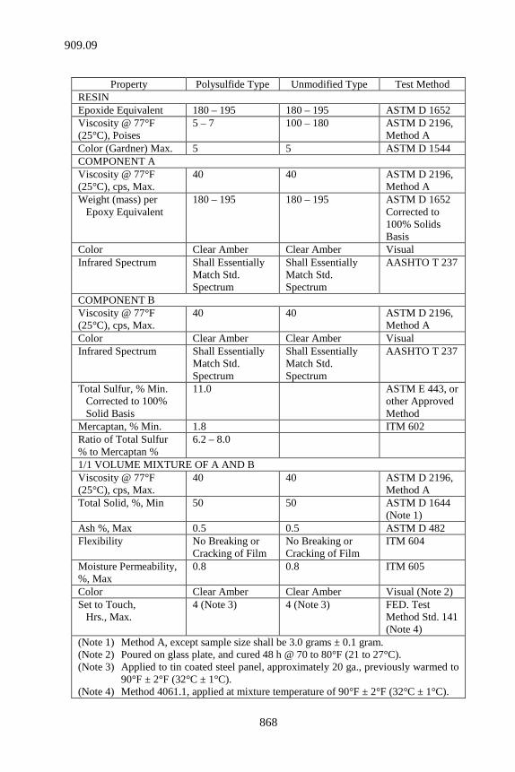
868
Property Polysulfide Type Unmodified Type Test Method
RESIN Epoxide Equivalent 180 – 195 180 – 195 ASTM D 1652 Viscosity @ 77°F (25°C), Poises
5 – 7 100 – 180 ASTM D 2196, Method A
Color (Gardner) Max. 5 5 ASTM D 1544 COMPONENT A Viscosity @ 77°F (25°C), cps, Max.
40 40 ASTM D 2196, Method A
Weight (mass) per Epoxy Equivalent
180 – 195 180 – 195 ASTM D 1652 Corrected to 100% Solids Basis
Color Clear Amber Clear Amber Visual Infrared Spectrum Shall Essentially
Match Std. Spectrum
Shall Essentially Match Std. Spectrum
AASHTO T 237
COMPONENT B Viscosity @ 77°F (25°C), cps, Max.
40 40 ASTM D 2196, Method A
Color Clear Amber Clear Amber Visual Infrared Spectrum Shall Essentially
Match Std. Spectrum
Shall Essentially Match Std. Spectrum
AASHTO T 237
Total Sulfur, % Min. Corrected to 100% Solid Basis
11.0 ASTM E 443, or other Approved Method
Mercaptan, % Min. 1.8 ITM 602 Ratio of Total Sulfur % to Mercaptan %
6.2 – 8.0
1/1 VOLUME MIXTURE OF A AND B Viscosity @ 77°F (25°C), cps, Max.
40 40 ASTM D 2196, Method A
Total Solid, %, Min 50 50 ASTM D 1644 (Note 1)
Ash %, Max 0.5 0.5 ASTM D 482 Flexibility No Breaking or
Cracking of Film No Breaking or Cracking of Film
ITM 604
Moisture Permeability, %, Max
0.8 0.8 ITM 605
Color Clear Amber Clear Amber Visual (Note 2) Set to Touch, Hrs., Max.
4 (Note 3) 4 (Note 3) FED. Test Method Std. 141 (Note 4)
(Note 1) Method A, except sample size shall be 3.0 grams ± 0.1 gram. (Note 2) Poured on glass plate, and cured 48 h @ 70 to 80°F (21 to 27°C). (Note 3) Applied to tin coated steel panel, approximately 20 ga., previously warmed to
90°F ± 2°F (32°C ± 1°C). (Note 4) Method 4061.1, applied at mixture temperature of 90°F ± 2°F (32°C ± 1°C).
909.09
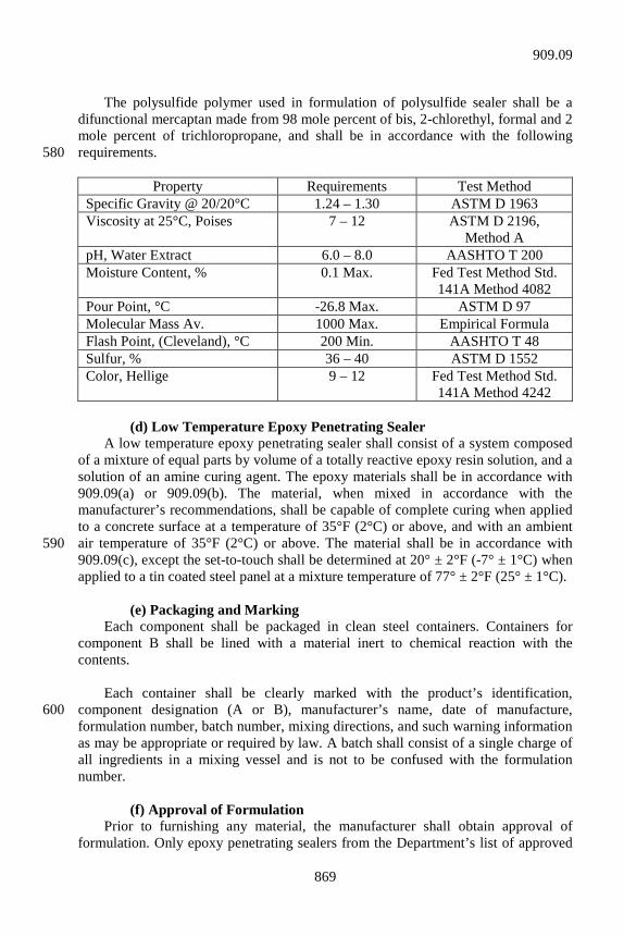
869
The polysulfide polymer used in formulation of polysulfide sealer shall be a difunctional mercaptan made from 98 mole percent of bis, 2-chlorethyl, formal and 2 mole percent of trichloropropane, and shall be in accordance with the following requirements. 580
Property Requirements Test Method Specific Gravity @ 20/20°C 1.24 – 1.30 ASTM D 1963 Viscosity at 25°C, Poises 7 – 12 ASTM D 2196,
Method A pH, Water Extract 6.0 – 8.0 AASHTO T 200 Moisture Content, % 0.1 Max.
Fed Test Method Std. 141A Method 4082
Pour Point, °C -26.8 Max. ASTM D 97 Molecular Mass Av. 1000 Max. Empirical Formula Flash Point, (Cleveland), °C 200 Min. AASHTO T 48 Sulfur, % 36 – 40 ASTM D 1552 Color, Hellige 9 – 12 Fed Test Method Std.
141A Method 4242 (d) Low Temperature Epoxy Penetrating Sealer A low temperature epoxy penetrating sealer shall consist of a system composed of a mixture of equal parts by volume of a totally reactive epoxy resin solution, and a solution of an amine curing agent. The epoxy materials shall be in accordance with 909.09(a) or 909.09(b). The material, when mixed in accordance with the manufacturer’s recommendations, shall be capable of complete curing when applied to a concrete surface at a temperature of 35°F (2°C) or above, and with an ambient air temperature of 35°F (2°C) or above. The material shall be in accordance with 590 909.09(c), except the set-to-touch shall be determined at 20° ± 2°F (-7° ± 1°C) when applied to a tin coated steel panel at a mixture temperature of 77° ± 2°F (25° ± 1°C). (e) Packaging and Marking Each component shall be packaged in clean steel containers. Containers for component B shall be lined with a material inert to chemical reaction with the contents. Each container shall be clearly marked with the product’s identification, component designation (A or B), manufacturer’s name, date of manufacture, 600 formulation number, batch number, mixing directions, and such warning information as may be appropriate or required by law. A batch shall consist of a single charge of all ingredients in a mixing vessel and is not to be confused with the formulation number. (f) Approval of Formulation Prior to furnishing any material, the manufacturer shall obtain approval of formulation. Only epoxy penetrating sealers from the Department’s list of approved
909.09
870
Coating Formulations shall be used. Epoxy penetrating sealers will be placed and maintained on the Department’s list of approved Coating Formulations in accordance 610 with ITM 606. 909.10 Proprietary PCC Sealers Proprietary PCC sealers shall be selected from the Department’s list of approved Other Concrete Sealers. A proprietary PCC sealer may be added to the approved list by completing the requirements in accordance with ITM 806, Approved List Procedure C. (a) Properties The proprietary PCC sealer shall be in accordance with NCHRP 244, Series IV, 620 Southern Climate Weathering Test and possess the following properties. Property Requirement Reduction of Chloride Ion Content 90% of the Control Active Ingredients, Minimum Silane Based 20% Siloxane Based 15% Others 10% 630 (b) Test Report The testing shall be performed by a recognized laboratory in accordance with ITM 806. The proprietary PCC sealers shall be delivered to the jobsite in unopened containers with the manufacturer’s numbered seal intact. 909.11 Epoxy-Resin-Base System for Bonding Plastic Concrete to Hardened Concrete 640 Two-component, epoxy-resin bonding systems for use in bonding freshly mixed concrete to hardened concrete shall be in accordance with ASTM C 881 for type II, grade 2, and the class consistent with the ambient temperature as follows. Class A for use below 40°F (4°C); class B for use between 40°F (4°C) and 60°F (16°C); and class C for use above 60°F (16°C). Material furnished under this specification shall be covered by a type C certification in accordance with 916. 909.12 Epoxy Resin Additives for Injection into Concrete The epoxy resin adhesive shall be of low enough viscosity such that it flows to the next open port in the surface seal material. The adhesive shall be capable of 650 penetrating crack widths down to 0.005 in. (125 µm). The adhesive shall be capable of bonding to dry or damp surfaces. The adhesive shall exhibit a slant shear strength exceeding the concrete strength when tested fully cured in accordance with AASHTO T 237.
909.10
871
The surface seal material shall have adequate strength to hold injection fittings in place and to resist injection pressures adequately to prevent leakage during injection. The epoxy resin adhesive for injection shall be covered by a type C certification 660 in accordance with 916.
SECTION 910 – METAL MATERIALS 910.01 Reinforcing Bars and Dowel Bars (a) General Unless otherwise specified, bars for concrete reinforcement shall be deformed billet steel, grade 60 (420). Tie bar assemblies used in lieu of bent tie bars shall be in accordance with the minimum total ultimate strength and minimum total yield strength requirements specified for bent tie bars; bend test and elongation will not be required. 10 Reinforcement used in precast or precast prestressed concrete structural members, including deck panels, shall be in accordance with ASTM A 615 grade 60 (A 615M, grade 420) or ASTM A 706 grade 60 (A 706M grade 420). Reinforcing bars shall be furnished by selecting bars made by a manufacturer on the list of Certified Uncoated Reinforcing Bar Manufacturers and in accordance with ITM 301. When shipped to the project site, the reinforcing bars shall be accompanied by the type of certifications specified in ITM 301 and in accordance with 916. 20 (b) Specific Requirements 1. Billet Steel Bars Billet steel bars shall be in accordance with ASTM A 615 (A 615M). 2. Threaded Tie Bar Assembly The threaded tie bar assembly shall be deformed billet steel, grade 60 (420) or higher, in accordance with 910.01(b)1 and a coupling device. The minimum strength of the tie bar assembly shall be 125% of the designated yield strength of the bar from which it is manufactured. Where epoxy coated threaded tie bar assemblies are 30 specified, an epoxy coating with a minimum film thickness of 6 mils (150 µm) shall be applied to the coupling device and epoxy coated reinforcing bars shall be provided in accordance with 910.01(b)9 with the exception that the epoxy coated bar is not required to be furnished from the list of Certified Reinforcing Bar Epoxy Coaters.
910.01
872
3. Splicing Systems Reinforcing bar splicing systems shall be selected from the list of approved Reinforcing Bar Splicing Systems. A manufacturer may request to have a splicing system added to the list by submitting 3 randomly selected epoxy coated bars of each 40 bar designation to be included as an approved splicing system on the list. The samples furnished shall be assembled. The splicing system will be tested for tensile strength in accordance with ASTM A 370 and shall reach 150% of the specified yield on all 3 samples for each bar size submitted. Splicing systems demonstrating consistent, repeatable, and passing test results will be added to the list. Approved bar designations will be noted on the list. 4. Blank 5. Steel Welded Wire Reinforcement, Smooth 50 Smooth steel welded wire reinforcement shall be in accordance with ASTM A 185, except as follows. a. The wire used in manufacturing the welded wire reinforcement
shall be as drawn, not galvanized, unless otherwise specified. b. The welded wire reinforcement shall be furnished in flat sheets
unless otherwise permitted or specified. c. Weld shear tests of welded wire reinforcement shall be 60
performed by the manufacturer on the test specimens obtained for testing tensile properties in accordance with the Frequency Manual. If there is weld shear failure, additional test specimens shall be tested in accordance with ASTM A 185.
6. Steel Welded Wire Reinforcement, Deformed Deformed steel welded wire reinforcement shall be in accordance with ASTM A 497, except as follows. a. The wire used in manufacturing the welded wire reinforcement 70
shall be in accordance with ASTM A 496. b. The welded wire reinforcement shall be furnished in flat sheets
unless otherwise specified or permitted. c. Weld shear tests of welded wire reinforcement shall be
performed by the manufacturer on the test specimens obtained for testing tensile properties in accordance with the Frequency Manual. If there is shear failure, additional test specimens shall be tested in accordance with ASTM A 497. 80
910.01
873
7. Uncoated 7 Wire Strand Uncoated 7 wire strand shall be in accordance with ASTM A 416. The strand shall have the minimum tensile strength and initial tension shown on the plans. Uncoated 7 wire strand shall be covered by a type A certification in accordance with 916. The certification shall include the lot number, size, cross-sectional area, yield strength, breaking strength, strand composition, modulus of elasticity, and a load-elongation curve for each size of strand supplied. 90 8. Steel Spiral Reinforcement Steel spiral reinforcement shall be either: a. deformed billet steel, ASTM A 615, grade 60 (A 615M, grade
420); or b. cold drawn steel wire, ASTM A 82. 9. Epoxy Coated Reinforcing Bars Epoxy coated reinforcing bars shall be furnished by selecting bars coated from 100 an applicator’s plant on the list of Certified Reinforcing Bar Epoxy Coaters and in accordance with ITM 301. The epoxy coating material shall be selected from the list of approved Epoxy Coating for Steel. Epoxy coated reinforcing bars shall be in accordance with ASTM A 775 (A 775M), except as follows. a. the bars shall be in accordance with 910.01(b)1; b. the coating color shall contrast with the color of iron oxide; 110 c. tensile and bend tests shall be performed on the bars. If an
examination of the bend test specimen suggests the need, the adhesion of the coating shall be checked by subjecting additional specimens to the 120° bend test. Hairline cracks without bond loss will be acceptable provided there are not more than 2 and the length of either crack does not exceed 1/4 in. (6 mm). The average coating thickness shall be 9 to 14 mils (225 to 350 µm) after cure. The thickness measurements shall be made in accordance with ASTM G 12. The coating 120 thickness shall be an average based on 12 individual readings. No specific correction for the base preparation process shall be applied to the thickness measurements.
d. epoxy coated reinforcing bars furnished by coaters on the list of
approved Certified Reinforcing Bar Epoxy Coaters shall be
910.01
874
accompanied by the types of certifications specified in ITM 301 and in accordance with 916.
e. repair and handling procedures shall be in accordance with 130
703.04. The patching material shall be in accordance with the Annex to ASTM D 3963 (D 3963M).
Epoxy coated support devices for epoxy coated reinforcing bars shall be in accordance with ASTM A 775 (A 775M), except as follows. a. the steel shall be in accordance with 910.01(b)1; b. the coating color shall contrast with the color of iron oxide; 140 c. the coating thickness shall be 6 to 20 mils (150 to 500 µm)
after cure. The thickness measurements shall be made in accordance with ASTM G 12.
10. Dowel Bars Dowel bars shall be in accordance with AASHTO M 254 and the metal core in accordance with AASHTO M 255, grade 60 (420). The dowel bar area and weight (mass) for the nominal bar diameter shall be as follows. Nominal Bar Cross Sectional Weight (Mass) 150 Diameter, in. (mm) Area, sq in. (mm2) lb/ft (kg/m) 1 (25) 0.79 (510) 2.670 (3.973) 1 1/4 (32) 1.23 (794) 4.172 (6.209) 1 5/16 (33) 1.35 (871) 4.600 (6.846) 1 1/2 (38) 1.77 (1142) 6.008 (8.941) Dowel bars shall be coated with an epoxy coating material selected from the list of approved Epoxy Coating for Steel. The coating thickness after cure shall be a minimum of 7 mils (175µm). Dowel bars shall not have burring or other deformation 160 restricting slippage in concrete. Dowel bar ends shall be saw cut. Chips from the cutting operation shall be removed from coated bars. Dowel bars shall be furnished by selecting bars made by a coater and manufacturer on the list of approved Certified Reinforcing Bar Epoxy Coaters and in accordance with ITM 301. When shipped to the project site, the dowel bars shall be accompanied by the types of certifications specified in ITM 301 and in accordance with 916. (c) Inspection, Sampling, and Testing 170 All reinforcing bars may be inspected, sampled, and tested after delivery to the project.
910.01
875
910.02 Structural Steel (a) Structural Steel Unless otherwise specified, structural steel shall be in accordance with ASTM A 709, grade 36 (A 709M, grade 250). (b) Weathering Steel 180 Steel in accordance with ASTM A 709 that has an atmospheric corrosion resistance index that meets or exceeds the index value shown in ASTM A 709. (c) High Strength Structural Steel This steel, when specified, shall be in accordance with ASTM A 709, grade 100 (A 709M, grade 690); ASTM A 709, grade 50 (A 709M, grade 345); or ASTM A 709, grade 50W (A 709M, grade 345W). The corrosion resistance of ASTM A 709, grade 50W (A 709M, grade 345W) steel shall be at least 4 times that of structural carbon steel. The steel fabricator, 190 when placing the order, shall state that the steel is for bridge use, and that the steel shall be used in the bare, unpainted condition. All fasteners used in conjunction with ASTM A 709, grade 50W (A 709M, grade 345W) steel shall be friction type high-strength steel bolts in accordance with ASTM A 325 (A 325M) type III. Certification and a sample shall be submitted to the Engineer prior to start of erection. All plates and bars produced from ASTM A 572 (A 572M) steel over 3/4 in. (19 mm) in thickness shall be “killed fine grain practice”. 200 (d) High Performance Steel High performance steel, HPS, shall be in accordance with ASTM A 709 (A 709M). In addition to the conditions listed in Section 6.7 of ASTM A 709 (A 709M), high performance steel may be furnished as hybrid/mixed design structural components using high performance steel plates in combination with high strength, low alloy steel plates and shapes, for welded or bolted applications in bridge construction. The impact testing requirements for HPS in accordance with 10.1 and 10.2 of 210 ASTM A 709 (A 709M) shall meet temperature zone 2. (e) Charpy V-Notch Toughness Tests Structural steel, except members exempted below, shall meet the longitudinal Charpy V-Notch test requirement as specified in the following table for the type or types of steel specified or furnished. Sampling and testing procedures shall be in accordance with ASTM A 673 (A 673M). The H frequency of heat testing shall be
910.02
876
used. Charpy V-Notch test data shall be included on the mill test reports for structural steel specified in 711.08 and 916. 220
ASTM Designation Thickness – in. (mm)
Foot-Pounds Joule (J)
@ 40°F (4°C) A 709 grade 36 (A 709M grade 250)
15 (20.3)
A 709 grade 50* (A 709M grade 345)*
Up to 4 in. (100 mm) mechanically fastened Up to 2 in. (50 mm) welded
15 (20.3) 15 (20.3)
A 709 grade 50W* (A 709M grade 345W)*
Up to 4 in. (100 mm) mechanically fastened Up to 2 in. (50 mm) welded Over 2 in. to 4 in. (50 to 100 mm) welded
15 (20.3) 15 (20.3) 20 (27.1)
* If the yield point of the material exceeds 65,000 psi (450 MPa), the temperature for the CVN value for acceptability shall be reduced by 15°F (-10°C) for each increment of 10,000 psi (69 MPa) above 65,000 psi (450 MPa).
This test requirement shall apply to all structural steel members and/or components except diaphragms, cross frames, stiffeners, lateral bracing, railroad ballast retainers and components, shoe assemblies, expansion joints, and compression members of trusses. (f) Mill Test Reports Mill test reports for structural steel shall be in accordance with 711.08 and 916 and shall include Charpy-Impact test data as set out in 910.02(e). 230 (g) High Strength Bolts, Nuts, and Washers 1. General Use High strength bolts shall be in accordance with ASTM A 325 (A 325M). Type 3 bolts will be required if the structural steel is to remain unpainted. High strength nuts shall be of the grade and finish specified in ASTM A 325 (A 325M) and in accordance with ASTM A 563 (A 563M) or ASTM A 194 (A 194M). High strength washers shall be of the type specified in ASTM A 325 (A 325M) and in accordance with ASTM F 436. The bolts, washers, and nuts shall be coated after fabrication in accordance with ASTM A 153, class C or AASHTO M 298, class 55. 240 2. Assembly of Structural Steel in Bridges High strength bolts, nuts, and washers used in the assembly of structural steel in bridges, excluding shoes and bearing assemblies, shall be provided in accordance with 910.02(f)1 and the following additional requirements. a. Bolts The maximum tensile strength shall be 150,000 psi (1,034 MPa) for bolts 1 in. (25 mm) or less in diameter. The maximum tensile strength shall be 120,000 psi (827 MPa) for bolts greater than 1 in. (25 mm) in diameter. The maximum hardness 250 shall be 33 Rc.
910.02
877
b. Nuts The nuts shall be in accordance with ASTM A 563 (A 563M), grade DH; or ASTM A 194 (A 194M), grade 2H. c. Tests (1) Rotational Capacity High strength fasteners shall be subjected to the rotational capacity test in 260 accordance with ASTM A 325, Section 6.3. The fastener shall complete 2 times the required number of turns from snug tight conditions in accordance with AASHTO LRFD Bridge Construction Specifications, in a Skidmore-Wilhelm calibrator or equivalent tension measuring device without stripping or failure. During this test, the maximum recorded tension shall be at least 1.15 times the required fastener tension indicated in AASHTO LRFD Bridge Construction Specifications. The measured torque required to produce the required fastener tension shall not exceed the value obtained by the following equation.
Torque = 0.25 PD 270 where: Torque = Measured Torque, (foot-pounds) (newton meters) P = Measured Bolt Tension, (pounds) (newtons) D = Nominal Diameter (feet) (meters) (2) Proof Loads Proof load tests for bolts shall be conducted in accordance with ASTM F 606, Section 3.2.3. Proof load test for nuts shall be conducted in accordance with ASTM F 606, Section 4.2. 280 (3) Wedge Tension Test The wedge tests of full size bolts shall be conducted in accordance with ASTM F 606, Section 3.5. d. Certification The supplier shall provide a certification of compliance with all requirements for high strength bolts, nuts, and washers used in the assembly of structural steel in bridges. The certification, in addition to complying with the applicable requirements of 916, shall include the lot number on the shipping package and indicate when or 290 where all testing was performed. (h) Bolts other than High Strength Bolts 1. General Bolts shall be unfinished, turned, or ribbed bolts conforming to the requirements for Grade A bolts of specification for low carbon steel externally and internally
910.02
878
threaded fasteners, ASTM A 307. Bolts shall have single, self-locking nuts or double nuts unless otherwise shown on the plans or in the special provisions. Beveled washers shall be used where bearing faces have a slope of more than 1:20 with 300 respect to a plane normal to the bolt axis. Bolts, washers, and nuts utilized in the U channel steel post splice as shown on the plans shall be in accordance with ASTM A 449, SAE J429-G7.9, or ASTM A 325 (A 325M) and shall be galvanized. 2. Unfinished Bolts Unfinished bolts shall be furnished unless other types are specified. 3. Turned Bolts 310 The surface of the body of turned bolts shall meet the ANSI roughness rating value of 125. Heads and nuts shall be hexagonal and standard dimensions for bolts of the nominal size specified or the next larger nominal size. Diameter of threads shall be equal to the body of the bolt or the nominal diameter of the bolt specified. Holes for turned bolts shall be carefully reamed. Bolts furnished shall provide for a light driving fit. Threads shall be entirely outside of the holes. A washer shall be provided under the nut. 4. Ribbed Bolts The body of ribbed bolts shall be of an approved form with continuous 320 longitudinal ribs. The diameter of the body measured on a circle through the points of the ribs shall be 5/64 in. (2 mm) greater than the nominal diameter specified for the bolts. Ribbed bolts shall be furnished with round heads conforming to requirements of ANSI B 18.5 unless otherwise specified. Nuts shall be hexagonal, either recessed or with a washer of suitable thickness. Ribbed bolts shall make a driving fit with the holes. The hardness of the ribs shall be such that the ribs do not mash down enough to permit the bolts to turn in the holes during tightening. If for any reason the bolt twists before drawing tight, the hole shall be carefully reamed and an over sized bolt used as a replacement. 330 910.03 Permanent Metal Forms Metal bridge deck forms and supports shall be fabricated from steel in accordance with ASTM A 653 (A 653M) for grades A through E having a coating class of G165. Material furnished under this specification shall be covered by the type of certification specified in the Frequency Manual and in accordance with 916. The certification shall list the yield tensile stresses, the ultimate tensile stresses, the ultimate tensile elongations, the base metal thicknesses, the weights (masses) of the galvanized coating, and shall certify that the material complies with the specified 340 material requirements. The properties and parameters shall be listed for each gage (thickness) of material used in the panels and the hardware necessary to erect them. The materials will be sampled at the work site and shall include a representative
910.03
879
portion of a panel of each gage (thickness) to be used and a representative portion of each type and size of hardware necessary to erect the panels, excluding the fasteners. 910.04 Steel Forgings and Steel Shafting (a) Carbon Steel Forgings Steel forgings shall be in accordance with ASTM A 668 for carbon steel 350 forgings for general industrial use. Class F forgings shall be furnished unless otherwise specified. (b) Cold Finished Carbon Steel Shafting Shafting shall be in accordance with ASTM A 108 for cold finished carbon steel bars and shafting. Grade designation 1016-1030, inclusive, shall be furnished unless otherwise specified. (c) Alloy Steel Forgings Alloy steel forgings shall be in accordance with ASTM A 668 for alloy steel 360 forgings for general industrial use. Class G forgings shall be furnished unless otherwise specified. (d) Certification Steel forgings and steel shafting shall be covered by a mill certification reporting the test results of: 1. chemical analysis; 2. heat treatment, not required for shafting; 370 3. tensile strength, yield strength, and elongation. Elongation is not required for shafting. 910.05 Castings The casting design shall be proof loaded to 40,000 (178 kN) in accordance with Federal Specification FF-F-621. Castings shall be in accordance with the plan dimensions and to the following requirements for the designated materials. A certified inspection report shall be submitted by the manufacturer with each shipment 380 of castings, except as otherwise provided herein. Inspection and testing shall be done by the manufacturer. The certified inspection report shall list the casting date, casting number, and the type of material, such as gray iron, ductile iron, etc. It shall state that inspection and testing has been performed, that all parts shipped meet the pertinent specification requirements, and that all component parts fit. The supporting test results, including proof load data, shall be retained and be available on request for a period of 7 years. All castings shall have the manufacturer’s identification and the date of manufacture cast on an exposed surface. Acceptance of castings will be based on the certified inspection report, visual inspection, and check measurements.
910.05
880
390 (a) Steel Castings Chromium alloy steel castings shall be in accordance with ASTM A 743 (A 743M). Grade CA 15 shall be furnished unless otherwise specified. (b) Iron Castings Iron casting shall be gray iron castings in accordance with ASTM A 48, class No. 35B, unless otherwise specified. Tension tests will be required for all castings including drainage castings. Castings shall be true to pattern in form and dimensions. A tolerance of ± 1/8 in. 400 (± 3 mm) in general dimensions as shown on the plans will be permitted with the exception that the tolerance in the dimensions of grates or covers and the openings into which they fit shall be limited to ± 1/16 in. (2 mm). All castings shall weigh at least 95% of the specified weight (mass) of that type cast to the exact dimensions shown on the plans. They shall be free from sponginess, cracks, blowholes, warping, sand inclusions, cold shots, cold shuts, chilled iron shrinks, or any defects which would affect the strength and value for the intended purpose. The castings shall completely fill the molds and shall not be removed until properly cooled. The casting date and a casting code number shall be cast on each casting. 410 All corners of the castings shall be filleted and outside corners and edges shall be rounded to a radius of not less than 1/8 in. (3 mm). All contact surfaces between different castings shall present a firm and even bearing without rattling or rocking. The lid frame bearing surfaces on all round castings shall be machine milled to provide true bearings around the entire circumference. All other contact surfaces shall be ground. All castings shall be cleaned of molding or core sand, rust, scale, and foreign material just prior to shipment. Iron castings shall be delivered unpainted. 420 (c) Ductile Iron Castings These castings shall be in accordance with ASTM A 536. Grade 65-45-12 shall be furnished unless otherwise specified. In addition, they shall be in accordance with all requirements of 910.05(b), except the first paragraph. (d) Malleable Castings These castings shall be in accordance with ASTM A 47 (A 47M). Grade No. 32510 or 35018 shall be furnished unless otherwise specified. In addition, they shall be in accordance with all requirements of 910.05(b), except the first paragraph. 430 (e) Carbon Steel Castings These castings shall be in accordance with ASTM A 27 (A 27M). The grade shall be 60-30, 65-35, or 70-36.
910.05
881
Castings shall be true to pattern in form and dimensions and free from pouring faults, sponginess, cracks, blowholes, and any defects in positions affecting their strength and value for the service intended. Blowholes appearing on finished castings shall be located so that a straight line laid in any direction does not cut a total length of cavity greater than 1 in. (25 mm) in 440 any 1 ft (0.3 m) nor shall any single hole exceed 1 in. (25 mm) in any dimension or have an area greater then 1/2 sq in. (323 mm2). Blowholes shall not be deep enough to affect the strength of the casting adversely. Minor defects which do not impair strength may, with approval, be welded by an approved process. Defects shall be removed in solid metal by chipping, drilling, or other satisfactory methods and, after welding, the castings shall be annealed if required. Castings which have been welded without permission will be rejected. No sharp unfilleted angles or corners will be allowed. 450 910.06 Bronze and Copper Alloy (a) Bronze Castings Bronze castings shall be in accordance with ASTM B 22, alloys 911 or 913. Material furnished under this specification shall be covered by a type A certification in accordance with 916. (b) Copper Alloy Plates Copper alloy plates shall be in accordance with ASTM B 100. Material furnished under this specification shall be covered by a type A certification in 460 accordance with 916. 910.07 Steel Components of MSE Retaining Walls (a) Backing Mats, Clevis Connector, Connector Bar, and Wire-Facing 1. Backing Mats Backing mats shall be smooth steel welded wire reinforcement in accordance with 910.01(b)5. Galvanization, if required, shall be in accordance with ASTM A 123, coating grade 55, or ASTM B 695, class 55. The Engineer will test samples in 470 accordance with ASTM A 185. 2. Clevis Connector Clevis connectors, if used, shall be attached to the alignment templates using the bars provided with the forms. The vertical and horizontal alignment of the connectors shall be ±1/8 in. (±3 mm). The holes inside the loops shall be free of all concrete and debris, loose or otherwise. The clevis connector shall be fabricated of cold-drawn steel wire in accordance with ASTM A 82, and welded in accordance with ASTM A 884. Loops shall be 480
910.07
882
galvanized in accordance with ASTM A 153 class B-3, ASTM A 123, coating grade 55, or ASTM B 695 class 55. A type A certification in accordance with 916 shall be furnished for the clevis connector. The results of the tension, bend, and coating adhesion tests, and measurements of coating thickness and average weight of the coating, shall be included on the certification for the clevis connector. 3. Connector Bar The connector bar, if used, shall be fabricated of cold-drawn steel wire in 490 accordance with ASTM A 884, and galvanized, if so shown on the plans, in accordance with ASTM A 123, coating grade 55, or ASTM B 695 class 55. A type A certification in accordance with 916 shall be furnished for the connector bars. The results of the coating adhesion test and the measurements of coating thickness, average weight of the coating, and coating flexibility, shall be included on the certification for the connector bar. 4. Wire-Facing Wire-facing shall be smooth steel WWR in accordance with 910.01(b)5. 500 Galvanization, if required, shall be in accordance with ASTM A 123, coating grade 55, or ASTM B 695, class 55. All wire-facing shall be handled, stored, and shipped so as to eliminate the danger of excessive bending stresses. The Engineer will test samples in accordance with ASTM A 185. (b) Ground Reinforcement The ground reinforcement shall be either a deformed steel strip or a welded-wire grid. The grid or strip used shall be consistent with that used in the pullout test and shall be consistent throughout the project. 510 The grid shall consist of not less than 2 longitudinal wires, perpendicular to the wall, welded to equally-spaced cross ribs capable of developing passive pressure with the fill. The deformed strip shall be of constant width. The strip thickness shall vary only from the undeformed section to the deformed section as required to produce the pullout resistance. The face-panel edges shall be configured to conceal the joints. All horizontal and vertical joints shall be covered with a joint cover to prevent backfill leakage while passing water. 520 Ground-reinforcement units shall be hot rolled from bars to the required shape and dimensions. Physical and mechanical properties of the units shall be in accordance with ASTM A 572 Grade 65 (A 572M Grade 450). Tie strips shall be shop fabricated with hot-rolled steel in accordance with the minimum requirements of ASTM A 1011 Grade 50. Galvanization for ground-reinforcing units and tie strips shall be in accordance with ASTM A 123, coating grade 85 or ASTM B 695 class
910.07
883
80. All ground-reinforcement units and tie strips will be inspected to ensure that they are true to size and free from defects which can impair their strength and durability. A type A certification in accordance with 916 shall be furnished for ground 530 reinforcement prior to use of the materials. The results of the yield strength, coating thickness, and coating adhesion tests shall be shown on the certification. (c) Fasteners Fasteners shall consist of 1/2 in. (13 mm) diameter, bolts, nuts, and washers and shall otherwise be in accordance with 910.02(g)1 with the exception that the hardware shall be coated in accordance with ASTM A 153, class C or ASTM B 695, class 55. The supplier shall provide a certificate of compliance with all requirements for 540 high strength bolts, nuts, and washers used in the assembly of MSE retaining walls. The certification, in addition to complying with the applicable requirements of 916, shall include the lot number and heat number on the shipping package and indicate when or where all testing was performed. (d) Alignment Pins The rods used to align the face panels during construction shall be 3/4 in. (19 mm) diameter and 12 in. (300 mm) in length. The rods shall be mild steel, polyvinyl chloride, or fiberglass. A type C certification in accordance with 916 shall be furnished for the alignment pins. 550 910.08 Steel Bin-Type Retaining Wall Units Wall units shall consist of adjoining closed-face cells filled with structure backfill to form a gravity-type retaining structure. The cells shall be constructed of members in accordance with AASHTO M 218 (M 218M) that are bolted together. The necessary bolts and appurtenances shall be furnished for complete assembly of the units into a continuous closed-face wall of connected bins. Working drawings shall be submitted in accordance with 105.02. 560 The units shall present a uniform workmanlike appearance once assembled. The base metal shall be not less than 16 gage (1.6 mm). The steel sheets shall be galvanized on both sides in accordance with ASTM A 123, coating grade 85. All sheets will be inspected to ensure that they are true to size and free from defects, which may impair their strength and durability. A type A certification in accordance with 916 for the bin-wall sheets shall be furnished prior to use. The results of the steel yield strength and coating adhesion tests, and measurement of the coating thickness, shall be shown on the certification. 570
910.08
884
910.09 Guardrail Guardrail of the same type shall be interchangeable regardless of the source. Guardrail shall be supplied by a Certified Guardrail Supplier selected from the Department’s list of Approved Certified Guardrail Suppliers. Steel beam rail shall be galvanized, corrugated sheet steel beams in accordance with AASHTO M 180 as modified herein. The rails, including terminal sections, shall be either class A, base metal nominal thickness of 0.105 in. (2.67 mm), 12 gage, or class B, base metal nominal thickness or 0.135 in. (3.43 mm), 10 gage. They 580 shall be type 2, zinc coated with 3.60 oz/sq ft (1.1 kg/m2) minimum single spot and 4.00 oz/sq ft (1.22 kg/m2) minimum triple spot. Tests for adherence of the coating may be made including the test specified in ASTM A 123, when deemed necessary. Where beam rail is set on a curve of 150 ft (45.7 m) radius or less, the rail plate shall be shop curved with its traffic face concave or convex as required. The radii of curvature shall be in increments of 10 ft (3 m) from a radius of 150 to 50 ft (45.7 to 15.2 m) inclusive and in increments of 5 ft (1.5 mm) from a radius of 50 ft (15.2 m) to and including 20 ft (6.1 m). 590 The steel channels specified on the plans shall be standard 5 in. (127 mm) channels weighing 6.7 lb/ft (10.0 kg/m). The material shall be in accordance with ASTM A 36 (A 36M). The channel shall be galvanized in accordance with ASTM A 123 after fabrication. The weight (mass) of zinc coating per area of actual surface shall average not less than 2.0 oz/sq ft (610 g/m2) for any individual piece of channel. Construction details for the rails and channels shall be as shown on the plans. Whenever field fabrication, as approved, requires cutting or drilling, the cut or drilled member shall be coated with a high zinc dust-zinc oxide paint in accordance 600 with Federal Specification TT-P-641, type II, or Military Specifications DOD-P-21035. When spray paints are used, 2 coats shall be applied. 910.10 Guardrail Posts Guardrail posts shall be either steel or wood as specified and shall be in accordance with the following requirements. (a) Steel Guardrail Posts The dimensions of the steel guardrail posts shall be as shown on the plans. The material shall be in accordance with ASTM A 36 (A 36M). The posts shall be 610 galvanized in accordance with ASTM A 123 after fabrication. However, the weight (mass) of zinc coating per square foot (square meter) of actual surface shall not average less than 2.0 oz (610 g) for an individual post. The weight (mass) of the W6 x 15 post, after fabrication and coating, shall not be less than 14.60 nor more than 16.00 lb/ft (21.73 nor more than 23.81 kg/m).
910.09
885
Construction details shall be as shown on the plans. Whenever field fabrication, as approved, requires cutting or drilling, the cut or drilled member shall be coated with a high zinc dust-zinc oxide paint conforming to the requirements of Federal 620 Specification TT-P-641, or Military Specifications DOD-P-21035.When spray paints are used, 2 coats shall be applied. (b) Wood Guardrail Posts The wood guardrail posts shall be in accordance with 911.02(d). Dimensions and construction details shall be as shown on the plans. 910.11 Guardrail Accessories, Fittings, and Hardware These items consist of brackets, splice plates and bars, post anchors, diaphragms, clamps and clamp bars, end caps, connections, anchor rod assemblies, 630 deadmen, bolts, screws, nuts, washers and blockouts of the type, dimensions, and design shown on the plans. They shall be in accordance with the requirements set out below. Items of the same type shall be interchangeable regardless of the source. (a) For Steel Beam Guardrail 1. Post brackets, bars, plates and shapes for bridge railing brackets,
and plate washers shall be in accordance with ASTM A 36 (A 36M). Post brackets, bars, and plates and shapes for bridge railing brackets shall be galvanized in accordance with 910.10(a). 640 Plate washers shall be galvanized after fabrication in accordance with ASTM A 153. The weight (mass) of the W6 x 15 post bracket shall be in accordance with 910.10.
2. Splice plates and rail portion of bridge railing brackets shall be
class B, type 2, in accordance with the first paragraph of 910.09(a). 3. Bolts and nuts of the sizes specified on the plans shall be in
accordance with ASTM A 307. Cut washers and lock washers shall be standard round steel washers of the sizes specified on the plans. 650 The diameter of cut washers shall be 1 3/4 in. (44 mm) for 5/8 in. (16 mm) bolts and 2 in. (50 mm) for 3/4 in. (19 mm) bolts with a thickness of 0.134 in. (3.4 mm) ± 0.026 in. (0.66 mm) measured at the hole. The bolts, washers, and nuts shall be coated after fabrication in accordance with ASTM A 153, or be mechanically galvanized and conform to the coating thickness, adherence, and quality requirements for class C of ASTM A 153.
4. Whenever approved field fabrication requires cutting or drilling,
the cut or drilled members shall be coated with a high zinc 660 dust-zinc oxide paint conforming to Federal Specification TT-P-641, type II, or Military Specifications DOD-P21035. When spray paints are used, 2 coats shall be applied.
910.11
886
5. Pipe spacers of the size specified on the plans shall be galvanized
after fabrication in accordance with ASTM A 153, class C. The weight (mass) of coating per square foot (square meter) of actual surface shall average no less than 1.25 oz (381 g) for the specimen tested and shall be no less than 1 oz (305 g) for any individual specimen. 670
6. For breakaway cable terminal, and cable terminal anchor system,
the rail element, standard bolts, nuts, and washers shall be in accordance with 910.09 and requirements 1 and 3 of 910.11(a).
7. For cable terminal anchor system, the anchor bracket, end plate,
soil plate, bearing plate, strut and yoke shall be in accordance with AASHTO M 270 grade 250. They shall be zinc coated after fabrication in accordance with AASHTO M 111. The steel tube shall be in accordance with ASTM D 500 grade B and zinc coated 680 in accordance with AASHTO M 111. The post sleeve shall be in accordance with ASTM A 53 grade B and zinc coated in accordance with AASHTO M 111. The stud shall be in accordance with ASTM F 568 class 8.8, and zinc coated in accordance with AASHTO M 111. The threads shall be in accordance with ANSI B1.13M and shall be M24 by 3 class 6g pitch. The swaged fitting shall be in accordance with ASTM A 576 grade 1035, zinc coated in accordance with AASHTO M 111, and shall be annealed for cold swaging. A lock pin hole to accommodate a 1/4 in. (6 mm) plated spring-steel pin shall be drilled through the head of the 690 swaged fitting.
8. Timber blockouts shall be in accordance with 911.02(f). Alternate
material blockouts shall be in accordance with 926.03. High strength bolts shall be in accordance with ASTM A 325 (A 325M) or ASTM A 449. High strength nuts shall be in accordance with ASTM A 563 (A 563M), Grade B or better. Galvanizing shall be in accordance with ASTM A 153 or mechanically galvanized and conform to the coating thickness, adherence, and quality requirements for class C of ASTM A 153. Foundation plates and bearing 700 plates shall be in accordance with ASTM A 36 (A 36M), and shall be galvanized after fabrication in accordance with ASTM A 123, except the weight (mass) of zinc coating per square foot (square meter) of actual surface shall average no less than 2.0 oz (610 g) and shall be no less than 1.8 oz (549 g) for any individual specimen. Welding shall be in accordance with AWS D1.1. Terminal posts shall be fabricated from tubing meeting ASTM A 500, Grade B, or ASTM A 501 and from plates meeting ASTM A 36 (A 36M). Welding shall be in accordance with AWS D1.1. They shall be galvanized after fabrication in accordance
910.11
887
with ASTM A 123, except the weight (mass) of zinc coating per square yard (square 710 meter) of actual surface shall average no less than 2.0 oz (610 g). The average for any component part, including paddle plate, tubing, or base plate, shall be no less than 1.8 oz (549 g). The steel pipe in the type 5 anchor and the steel spacer tube in the transition type WGB shall be Schedule 40. Tapered washers may be of steel or malleable iron, and galvanized in accordance with ASTM A 153. 720 The wire rope used in the cable assemblies shall be in accordance with AASHTO M 30 and shall be 3/4 in. (19 mm) preformed, 6 by 19, wire strand core or independent wire rope core (IWRC), galvanized, right regular lay, manufactured of improved plow steel, with a minimum specified breaking strength of 42,800 lbf (190 kN). The swaged fitting, stud, and nut shall develop the breaking strength of the wire rope. The fitting shall be galvanized in accordance with ASTM A 123 before swaging. After galvanizing, the head and nut may be tapped 0.023 in. (0.6 mm) over the ANSI B1.1, class 2B tolerance. (b) For Steel Tube Guardrail 730 1. Channels and bars for connections, splice bars, and diaphragms
shall be in accordance with ASTM A 36 (A 36M). 2. Cap screws shall be stainless steel in accordance with ASTM
A 276, type 304 or 430. 3. Rail end caps shall be malleable iron castings in accordance with
ASTM A 47 (A 47M), grade 35018, or steel castings in accordance with ASTM A 27 (A 27M), grade 70-36. 740
4. Cut washers and lock washers shall be standard round steel
washers. The diameter of cut washers shall be 1 1/2 in. (37.5 mm) and 1/8 in. (3.2 mm) thick measured at the hole. Washers shall be coated after fabrication in accordance with requirement 3 of 909.11(a).
5. All materials other than cap screws and washers shall be
galvanized after fabrication in accordance with ASTM A 123. 750 6. When field fabrication, as approved, requires cutting or drilling,
the cut or drilled members shall be coated with a high zinc dust-zinc oxide paint conforming to the requirements of Federal Specification TT-P-641 type II or Military Specifications DOD-P-21035. When spray paint is used, 2 coats shall be applied.
910.11
888
910.12 Certification of Guardrail Suppliers Suppliers desiring to be on certification status will be approved upon request and added to the Department’s list of approved Certified Guardrail Suppliers. The written request shall be submitted to the Office of Materials Management. An approval 760 number will be assigned to each supplier to be used for identification acceptable of material. The supplier shall perform testing or shall obtain documentation to ensure the quality of the material incorporated into the work. The supplier shall prepare each month a type D certification in accordance with 916.02(e). Such certification shall contain the contract number; supplier’s name; supplier’s approval number; month of installation; rail manufacturer; bolt manufacturer; quantities of rail, channel, posts, block, and paddle posts incorporated 770 into the work; quantities of sawed timber posts and blocks for thrie-beam and W-beam guardrail incorporated into the work; and a statement that the materials furnished are in accordance with 910.09 through 910.12. The Department will inspect the steel beam guardrail on a randomly selected contract for compliance with specifications for a minimum of 1 time per year per supplier. Selected contracts with failing results will be adjudicated as a failed material in accordance with normal Department practice. 780 If the supplier shows negligence or the inability to ensure the delivery of specified materials, the supplier may be removed from the approved list. 910.13 Steel Fence Posts Tubular steel fence posts and line posts shall meet the following specifications and the requirements as shown on the plans. (a) Line Posts Line posts shall be in accordance with AASHTO M 281 and galvanized in 790 accordance with AASHTO M 111, Coating grade 65. Line posts for farm field fence shall be furnished with anchor plates. End, corner, pull, and gate posts for farm field type fence shall be furnished with braces and all fittings and details required to make a complete installation as shown on the plans. (b) Tubular Steel Fence Posts Two groups of tubular steel fence posts are included in these specifications. Tubular section posts shall have heavy malleable iron caps or pressed galvanized 800 steel caps. Such caps shall be made to provide a drive fit over the outside of the
910.12
889
section to exclude moisture. The weight (mass) per foot (meter) for tubular posts and braces shall be no less than 90% of the weight (mass) specified. Unless specified otherwise, the tubular steel fence post shall be group 1. 1. Group 1 Tubular steel fence posts for group 1 shall be hot-dipped zinc-coated and shall be in accordance with ASTM F 1083 except tests shall be conducted on sample posts selected as being representative of the posts furnished. The weight (mass) per foot (meter) will be acceptable provided it is at least 90% of the specified weight (mass). 810 2. Group 2 Tubular steel fence posts for group 2 shall have a minimum 50 ksi (345 MPa) yield strength and be in accordance with AASHTO M 181, except that the inner pipe surface may be galvanized in lieu of a zinc rich coating or hot dipped aluminum coated, Type 2, meeting the chemical requirements of AASHTO M 274. The aluminum coated, Type 2, steel fence posts shall be manufactured by roll forming aluminum coated, Type 2, steel strip and electric resistance welding it into tubular form. The outside of the weld area shall be metallized with commercially pure aluminum to a thickness sufficient to provide resistance to corrosion equal to that of 820 the remainder of the outside of the post. The aluminum coating weight (mass) shall be a minimum of 0.75 oz/sq ft (229 g/m2) average, and 0.70 oz/sq ft (214 g/m2) for an individual test specimen, as measured in accordance with ASTM A 428. Specimens for determining weight of coating shall be obtained in accordance with ASTM F 1083. (c) Fence Fastenings When fastenings are necessary for attaching the farm field fence to the posts, they shall be either galvanized or aluminum coated No. 9 (3.8 mm) wire, or galvanized or aluminum coated clamps of the manufacturer’s standard design. The 830 coating weights shall be a minimum of 0.60 oz/sq ft and 0.30 oz/sq ft (183 g/m2 and 92 g/m2) for galvanized and aluminum coated, respectively. A sufficient quantity of individual tie wires or clamps shall be furnished to provide for 5 attachments of the fencing to each line post and 1 tie wire for each strand of barbed or tension wire. Line posts for chain link type fence shall be furnished with the necessary tie wires or fabric bands for fastening the fabric to the posts. These fastenings shall be made of aluminum strip or wire of approved gage and design or of galvanized steel wire and may be in accordance with the manufacturer’s standard design. If galvanized steel wire ties are furnished, the wire shall be no smaller than No. 9 gage 840 (3.8 mm). A sufficient quantity of individual ties or bands shall be furnished to provide for attaching the fabric to each line post each 1 ft (0.3 m) or as called for on the plans.
910.13
890
910.14 Sign Posts (a) Steel, Flanged, Channel Posts 1. General Requirements Posts shall be made from open hearth, basic oxygen, or electric furnace steel 850 rolled from standard tee rails or new billets. The steel used in the posts shall conform to the physical properties of ASTM A 499, grade 60, and to the chemical compositions of ASTM A 1 for 91 lb/yd (45 kg/m) or larger steel rails. Posts fabricated from other steels will be acceptable providing that the following criteria are met. A notarized copy of a dynamic crash test report shall be furnished substantiating that the posts manufactured from this material, when double mounted in a 7 ft (2.1 m) span, conform to the breakaway requirements of AASHTO Standard Specifications for Structural Supports for Highway Signs, Luminaires, and Traffic Signals, except that the maximum change in velocity shall not exceed 16 ft/s 860 (4.9 m/s). For 2 posts in a 7 ft (2.1 m) path, impact performance may be estimated by multiplying the vehicle energy loss observed in a single post crash test by 2. This estimated double post energy loss may then be used to calculate an estimated impact velocity change and momentum change for a double post sign design. The minimum yield strength shall be 60,000 psi (414 MPa) and the minimum tensile strength shall be 90,000 psi (621 MPa). The tensile strength shall be determined by either the standard Rockwell Hardness test, Brinnel Hardness test, or by actual tensile test. The Rockwell Hardness shall be a minimum of B 91. The yield strength shall be determined by the 870 manufacturer by actual test. Tensile and yield strengths and chemical composition shall be determined by the average from the 3 latest test results the manufacturer has available at the time of shipment. These test results need not be made on the materials from which the posts were made. However, the tests must have been made within 90 days of shipment. Posts, except those used for temporary construction signs, temporary traffic signs, and temporary panel signs, shall be certified by a type B certification in accordance with 916. The certification shall include the above 3 test results and the elastic section modulus value in accordance with 910.14(a)3. Posts shall be of uniform flanged channel or U section such that the area of 880 contact between the post and the sign is symmetrical about the vertical axis of both sign and post. The back of each post shall be formed in a manner to ensure a solid bearing surface over the entire length of the post when mounted back to back. The bearing surface on the back of the post shall be flat. The length shall be as specified with a tolerance of ± 1 in. (± 25 mm). Sign posts shall be punched with 58 holes which shall be 3/8 in. (9.5 mm) in diameter located on the center-line and spaced on 1 in. (25 mm) centers beginning 1 in. (25 mm) from the top. The remainder of the post shall be punched with 3/8 in. (9.5 mm) holes on 1 in. (25 mm) or 2 in. (50 mm) centers. 890
910.14
891
The finished posts shall be machine straightened and have a smooth uniform finish free from cracks, flaws, injurious seams, laps, blisters, and edges which are ragged, sharp, and imperfect, or other defects affecting their strength, durability, or appearance. The maximum variation in straightness shall be no more than 1/4 in. in any 5 ft (6 mm in any 1.5 m) of length, or exceed in inches (millimeters) 1/4 times the number of feet (meter) of length divided by 5. Bolt holes of the diameter specified shall be accurately spaced vertically and centered horizontally so that holes will register for back to back application. All holes and sheared ends shall be commercially free from burrs. 900 The steel sign posts shall be galvanized in accordance with ASTM A 123. Galvanizing shall be the final process after all fabrication and punching has been completed. Posts saw cut after galvanizing shall have the cut surface treated with a zinc-based solder in rod form which complies with ASTM A 780. The cut surface shall not be treated until the fuse plate is installed and all bolts are tightened. The top of the fuse plate shall be 1 in. (25 mm) below the bottom of the sign. Posts saw cut before galvanizing shall have temporary fasteners provided with sufficient strength to prevent warping or deforming of the post during the 910 galvanization process. The surface under the temporary fasteners shall be treated with an approved zinc solder meeting the above mentioned specifications. The surface shall be treated before the fuse plate is installed. The break-away stubs shall be galvanized a minimum of 8 in. (200 mm) below the top of the concrete foundation. Steel posts shall be wired or strapped securely in bundles of not more than 2,000 lb (907 kg). They shall be nested in rows with the edges intermeshed so as to form a rectangular bundle and shall be fastened in such a manner that they do not slip or rub against each other and cause damage to the finish. Care shall be taken 920 during shipment to prevent the bundles from rubbing against each other and causing damage. Excessive damage to the finish during shipment will be cause for rejection of the damaged posts. 2. Deflection Test Requirements Posts will be tested as a simple beam with the flange in compression on non-restricting supports 24 in. (610 mm) apart. Test specimens shall be 28 in. ± 1/4 in. (711 mm ± 6.3 mm) long. A load of 1500, 3500, or 4600 lb (6672, 15569, or 20462 N), depending on the type of post, shall be applied at the center of the span with a mandrel of not less than 1 in. (25 mm) in diameter. Application of the load 930 shall be at a speed of not to exceed 0.03 in. (8 mm) per min. Deflection of the post upon application of the total load shall not exceed 0.16 in. (4 mm). The load shall then be removed. Deflection of the post 1 minute after removal of the load shall not exceed 0.01 in. (0.25 mm).
910.14
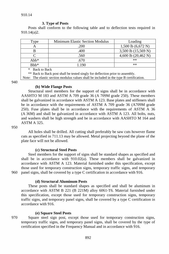
892
3. Type of Posts Posts shall conform to the following table and to deflection tests required in 910.14(a)2.
Type Minimum Elastic Section Modulus Loading A .200 1,500 lb (6,672 N) B .400 3,500 lb (15,569 N) C .560 4,600 lb (20,462 N)
Abb* .670 ** Bbb* 1.190 **
* Back to Back ** Back to Back post shall be tested singly for deflection prior to assembly. Note: The elastic section modulus values shall be included in the type B certification.
940 (b) Wide Flange Posts Structural steel members for the support of signs shall be in accordance with AASHTO M 183 and ASTM A 709 grade 36 (A 709M grade 250). These members shall be galvanized in accordance with ASTM A 123. Base plates and stiffeners shall be in accordance with the requirements of ASTM A 709 grade 36 (A709M grade 250). Fuse plates shall be in accordance with the requirements of ASTM A 36 (A 36M) and shall be galvanized in accordance with ASTM A 123. All bolts, nuts, and washers shall be high strength and be in accordance with AASHTO M 164 and ASTM A 325. 950 All holes shall be drilled. All cutting shall preferably be saw cuts however flame cuts as specified in 711.13 may be allowed. Metal projecting beyond the plane of the plate face will not be allowed. (c) Structural Steel Posts Steel members for the support of signs shall be standard shapes as specified and shall be in accordance with 910.02(a). These members shall be galvanized in accordance with ASTM A 123. Material furnished under this specification, except those used for temporary construction signs, temporary traffic signs, and temporary panel signs, shall be covered by a type C certification in accordance with 916. 960 (d) Structural Aluminum Posts These posts shall be standard shapes as specified and shall be aluminum in accordance with ASTM B 221 (B 221M) alloy 6061-T6. Material furnished under this specification, except those used for temporary construction signs, temporary traffic signs, and temporary panel signs, shall be covered by a type C certification in accordance with 916. (e) Square Steel Posts Square steel sign post, except those used for temporary construction signs, 970 temporary traffic signs, and temporary panel signs, shall be covered by the type of certification specified in the Frequency Manual and in accordance with 916.
910.14
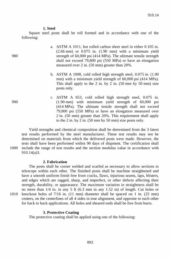
893
1. Steel Square steel posts shall be roll formed and in accordance with one of the following: a. ASTM A 1011, hot rolled carbon sheet steel in either 0.105 in.
(2.66 mm) or 0.075 in. (1.90 mm) with a minimum yield strength of 60,000 psi (414 MPa). The ultimate tensile strength 980 shall not exceed 79,800 psi (550 MPa) or have an elongation measured over 2 in. (50 mm) greater than 20%.
b. ASTM A 1008, cold rolled high strength steel, 0.075 in. (1.90
mm) with a minimum yield strength of 60,000 psi (414 MPa). This shall apply to the 2 in. by 2 in. (50 mm by 50 mm) size posts only.
c. ASTM A 653, cold rolled high strength steel, 0.075 in.
(1.90 mm) with minimum yield strength of 60,000 psi 990 (414 MPa). The ultimate tensile strength shall not exceed 79,800 psi (550 MPa) or have an elongation measured over 2 in. (50 mm) greater than 20%. This requirement shall apply to the 2 in. by 2 in. (50 mm by 50 mm) size posts only.
Yield strengths and chemical composition shall be determined from the 3 latest test results performed by the steel manufacturer. These test results may not be determined on materials from which the delivered posts were made. However, the tests shall have been performed within 90 days of shipment. The certification shall include the range of test results and the section modulus value in accordance with 1000 910.14(a)3. 2. Fabrication The posts shall be corner welded and scarfed as necessary to allow sections to telescope within each other. The finished posts shall be machine straightened and have a smooth uniform finish free from cracks, flaws, injurious seams, laps, blisters, and edges which are ragged, sharp, and imperfect, or other defects affecting their strength, durability, or appearance. The maximum variation in straightness shall be no more than 1/4 in. in any 5 ft (6.3 mm in any 1.52 m) of length. Cut holes or knockout holes of 7/16 in. (11 mm) diameter shall be spaced on 1 in. (25 mm) 1010 centers, on the centerlines of all 4 sides in true alignment, and opposite to each other for back to back applications. All holes and sheared ends shall be free from burrs. 3. Protective Coating The protective coating shall be applied using one of the following:
910.14
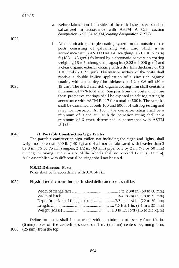
894
a. Before fabrication, both sides of the rolled sheet steel shall be galvanized in accordance with ASTM A 653, coating designation G 90. (A 653M, coating designation Z 275).
1020 b. After fabrication, a triple coating system on the outside of the
posts consisting of galvanizing with zinc which is in accordance with AASHTO M 120 weighing 0.60 ± 0.15 oz/sq ft (183 ± 46 g/m2) followed by a chromatic conversion coating weighing 15 ± 5 micrograms, µg/sq in. (0.02 ± 0.006 g/m2) and a clear organic exterior coating with a dry film thickness of 0.2 ± 0.1 mil (5 ± 2.5 µm). The interior surface of the posts shall receive a double in-line application of a zinc rich organic coating with a total dry film thickness of 1.2 ± 0.6 mil (30 ± 15 µm). The dried zinc rich organic coating film shall contain a 1030 minimum of 77% total zinc. Samples from the posts which use these protective coatings shall be exposed to salt fog testing in accordance with ASTM B 117 for a total of 500 h. The samples shall be examined at both 100 and 500 h of salt fog testing and rated for corrosion. At 100 h the corrosion rating shall be a minimum of 9 and at 500 h the corrosion rating shall be a minimum of 6 when determined in accordance with ASTM D 1654.
(f) Portable Construction Sign Trailer 1040 The portable construction sign trailer, not including the signs and lights, shall weigh no more than 300 lb (140 kg) and shall not be fabricated with heavier than 3 by 3 in. (75 by 75 mm) angles, 2 1/2 in. (63 mm) pipe, or 3 by 2 in. (75 by 50 mm) rectangular tubing. The rim size of the wheels shall not exceed 12 in. (300 mm). Axle assemblies with differential housings shall not be used. 910.15 Delineator Posts Posts shall be in accordance with 910.14(a)1. Physical requirements for the finished delineator posts shall be: 1050 Width of flange face ............................................ 2 to 2 3/8 in. (50 to 60 mm) Width of back ...................................................... 3/4 to 7/8 in. (19 to 22 mm) Depth from face of flange to back .................... 7/8 to 1 1/8 in. (22 to 29 mm) Length .............................................................. 7.0 ft ± 1 in. (2.1 m ± 25 mm) Weight (Mass) .............................................. 1.0 to 1.5 lb/ft (1.5 to 2.2 kg/m) Delineator posts shall be punched with a minimum of twenty-four 1/4 in. (6 mm) holes on the centerline spaced on 1 in. (25 mm) centers beginning 1 in. (25 mm) from the top. 1060
910.15
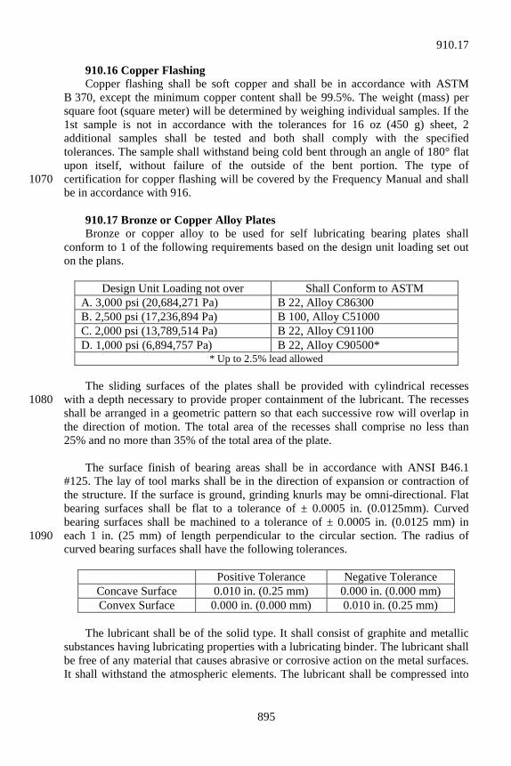
895
910.16 Copper Flashing Copper flashing shall be soft copper and shall be in accordance with ASTM B 370, except the minimum copper content shall be 99.5%. The weight (mass) per square foot (square meter) will be determined by weighing individual samples. If the 1st sample is not in accordance with the tolerances for 16 oz (450 g) sheet, 2 additional samples shall be tested and both shall comply with the specified tolerances. The sample shall withstand being cold bent through an angle of 180° flat upon itself, without failure of the outside of the bent portion. The type of certification for copper flashing will be covered by the Frequency Manual and shall 1070 be in accordance with 916. 910.17 Bronze or Copper Alloy Plates Bronze or copper alloy to be used for self lubricating bearing plates shall conform to 1 of the following requirements based on the design unit loading set out on the plans.
Design Unit Loading not over Shall Conform to ASTM A. 3,000 psi (20,684,271 Pa) B 22, Alloy C86300 B. 2,500 psi (17,236,894 Pa) B 100, Alloy C51000 C. 2,000 psi (13,789,514 Pa) B 22, Alloy C91100 D. 1,000 psi (6,894,757 Pa) B 22, Alloy C90500*
* Up to 2.5% lead allowed The sliding surfaces of the plates shall be provided with cylindrical recesses with a depth necessary to provide proper containment of the lubricant. The recesses 1080 shall be arranged in a geometric pattern so that each successive row will overlap in the direction of motion. The total area of the recesses shall comprise no less than 25% and no more than 35% of the total area of the plate. The surface finish of bearing areas shall be in accordance with ANSI B46.1 #125. The lay of tool marks shall be in the direction of expansion or contraction of the structure. If the surface is ground, grinding knurls may be omni-directional. Flat bearing surfaces shall be flat to a tolerance of ± 0.0005 in. (0.0125mm). Curved bearing surfaces shall be machined to a tolerance of ± 0.0005 in. (0.0125 mm) in each 1 in. (25 mm) of length perpendicular to the circular section. The radius of 1090 curved bearing surfaces shall have the following tolerances.
Positive Tolerance Negative Tolerance Concave Surface 0.010 in. (0.25 mm) 0.000 in. (0.000 mm) Convex Surface 0.000 in. (0.000 mm) 0.010 in. (0.25 mm)
The lubricant shall be of the solid type. It shall consist of graphite and metallic substances having lubricating properties with a lubricating binder. The lubricant shall be free of any material that causes abrasive or corrosive action on the metal surfaces. It shall withstand the atmospheric elements. The lubricant shall be compressed into
910.17
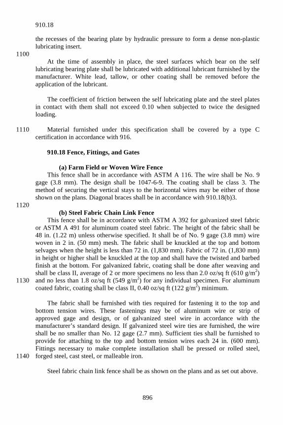
896
the recesses of the bearing plate by hydraulic pressure to form a dense non-plastic lubricating insert. 1100 At the time of assembly in place, the steel surfaces which bear on the self lubricating bearing plate shall be lubricated with additional lubricant furnished by the manufacturer. White lead, tallow, or other coating shall be removed before the application of the lubricant. The coefficient of friction between the self lubricating plate and the steel plates in contact with them shall not exceed 0.10 when subjected to twice the designed loading. Material furnished under this specification shall be covered by a type C 1110 certification in accordance with 916. 910.18 Fence, Fittings, and Gates (a) Farm Field or Woven Wire Fence This fence shall be in accordance with ASTM A 116. The wire shall be No. 9 gage (3.8 mm). The design shall be 1047-6-9. The coating shall be class 3. The method of securing the vertical stays to the horizontal wires may be either of those shown on the plans. Diagonal braces shall be in accordance with 910.18(b)3. 1120 (b) Steel Fabric Chain Link Fence This fence shall be in accordance with ASTM A 392 for galvanized steel fabric or ASTM A 491 for aluminum coated steel fabric. The height of the fabric shall be 48 in. (1.22 m) unless otherwise specified. It shall be of No. 9 gage (3.8 mm) wire woven in 2 in. (50 mm) mesh. The fabric shall be knuckled at the top and bottom selvages when the height is less than 72 in. (1,830 mm). Fabric of 72 in. (1,830 mm) in height or higher shall be knuckled at the top and shall have the twisted and barbed finish at the bottom. For galvanized fabric, coating shall be done after weaving and shall be class II, average of 2 or more specimens no less than 2.0 oz/sq ft (610 g/m2) and no less than 1.8 oz/sq ft (549 g/m2) for any individual specimen. For aluminum 1130 coated fabric, coating shall be class II, 0.40 oz/sq ft (122 g/m2) minimum. The fabric shall be furnished with ties required for fastening it to the top and bottom tension wires. These fastenings may be of aluminum wire or strip of approved gage and design, or of galvanized steel wire in accordance with the manufacturer’s standard design. If galvanized steel wire ties are furnished, the wire shall be no smaller than No. 12 gage (2.7 mm). Sufficient ties shall be furnished to provide for attaching to the top and bottom tension wires each 24 in. (600 mm). Fittings necessary to make complete installation shall be pressed or rolled steel, forged steel, cast steel, or malleable iron. 1140 Steel fabric chain link fence shall be as shown on the plans and as set out above.
910.18
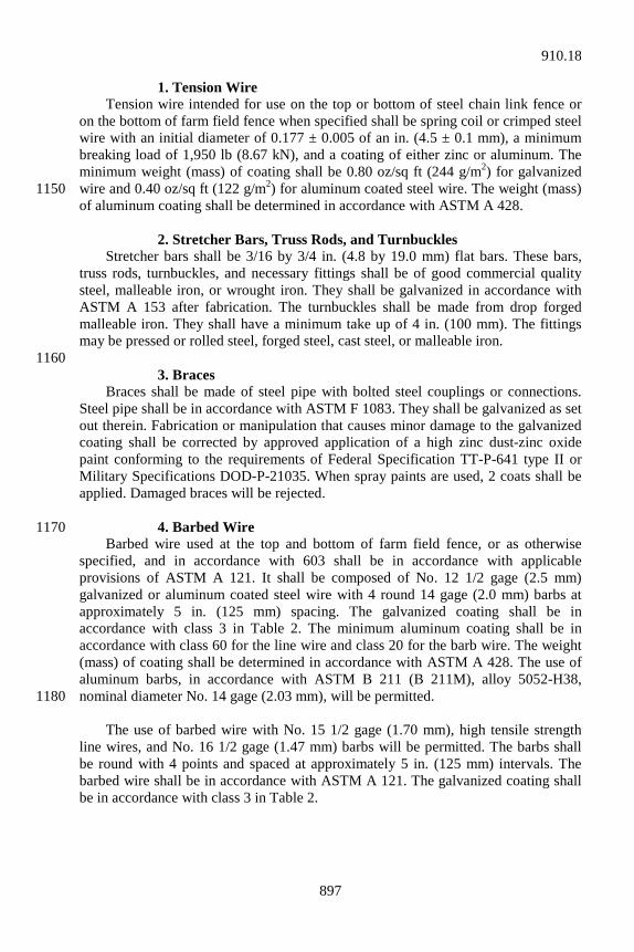
897
1. Tension Wire Tension wire intended for use on the top or bottom of steel chain link fence or on the bottom of farm field fence when specified shall be spring coil or crimped steel wire with an initial diameter of 0.177 ± 0.005 of an in. (4.5 ± 0.1 mm), a minimum breaking load of 1,950 lb (8.67 kN), and a coating of either zinc or aluminum. The minimum weight (mass) of coating shall be 0.80 oz/sq ft (244 g/m2) for galvanized wire and 0.40 oz/sq ft (122 g/m2) for aluminum coated steel wire. The weight (mass) 1150 of aluminum coating shall be determined in accordance with ASTM A 428. 2. Stretcher Bars, Truss Rods, and Turnbuckles Stretcher bars shall be 3/16 by 3/4 in. (4.8 by 19.0 mm) flat bars. These bars, truss rods, turnbuckles, and necessary fittings shall be of good commercial quality steel, malleable iron, or wrought iron. They shall be galvanized in accordance with ASTM A 153 after fabrication. The turnbuckles shall be made from drop forged malleable iron. They shall have a minimum take up of 4 in. (100 mm). The fittings may be pressed or rolled steel, forged steel, cast steel, or malleable iron. 1160 3. Braces Braces shall be made of steel pipe with bolted steel couplings or connections. Steel pipe shall be in accordance with ASTM F 1083. They shall be galvanized as set out therein. Fabrication or manipulation that causes minor damage to the galvanized coating shall be corrected by approved application of a high zinc dust-zinc oxide paint conforming to the requirements of Federal Specification TT-P-641 type II or Military Specifications DOD-P-21035. When spray paints are used, 2 coats shall be applied. Damaged braces will be rejected. 4. Barbed Wire 1170 Barbed wire used at the top and bottom of farm field fence, or as otherwise specified, and in accordance with 603 shall be in accordance with applicable provisions of ASTM A 121. It shall be composed of No. 12 1/2 gage (2.5 mm) galvanized or aluminum coated steel wire with 4 round 14 gage (2.0 mm) barbs at approximately 5 in. (125 mm) spacing. The galvanized coating shall be in accordance with class 3 in Table 2. The minimum aluminum coating shall be in accordance with class 60 for the line wire and class 20 for the barb wire. The weight (mass) of coating shall be determined in accordance with ASTM A 428. The use of aluminum barbs, in accordance with ASTM B 211 (B 211M), alloy 5052-H38, nominal diameter No. 14 gage (2.03 mm), will be permitted. 1180 The use of barbed wire with No. 15 1/2 gage (1.70 mm), high tensile strength line wires, and No. 16 1/2 gage (1.47 mm) barbs will be permitted. The barbs shall be round with 4 points and spaced at approximately 5 in. (125 mm) intervals. The barbed wire shall be in accordance with ASTM A 121. The galvanized coating shall be in accordance with class 3 in Table 2.
910.18

898
(c) Aluminum Fabric Chain Link Fence This fence shall be in accordance with the applicable requirements of 910.18(b) except for composition of materials. Requirements for the various component parts 1190 of aluminum fence shall be as shown in Table 1.
TABLE 1 ITEM ASTM
REFERENCE ALLOY ADDITIONAL INFORMATION
Fabric B 211 (B 211M) Alclad 5056 or 6061-T94
Barbed Wire - Line Barbs
B 211 (B 211M) 5062-0, H38, or 6061-T89
2-strand dia. 0.110 in. (2.8 mm) 4-pt barb. dia. 0.080 in. (2.0 mm) 5 in. (127.0 mm) space B 211 (B 211M) 5052-H38
Tension Wire B 211 (B 211M) Alclad 5056 or 6061-T94
Dia. 0.192 in. (4.9 mm); Note 1
Hog Ring Fasteners B 211 (B 211M) 6061-T94 Dia. 0.110 in. (2.8 mm) Wire Ties B 211 (B 211M) 1100-H18 Dia. 0.148 in. ( 3.8 mm) Flat band ties B 211 (B 211M) 3003-H14 1.2 in. (12.7 mm) wide; 0.06 in.
(1.5 mm) thick Stretcher Bars B 211 (B 211M) 6063-T6 3/4 in. (19.0 mm) by 1/4 in.
(6.4 mm); square edges Truss and Brace Rods
B 211 (B 211M) or B 221 (B 221M)
6061-T6 Dia. 3/8 in. (9.5 mm)
Turn Buckles B 26 (B 26M) (cast parts), B 211 (B 211M) (wrought)
356.0-T6 6061-T6
Bands B 221 (B 221M) 6063-T6 1/8 in. (3.2 mm) by 1 in. (25 mm) beveled edge
Bolts B 211 (B 211M) or B 221 (B 221M)
2024-T4 ASA B 18.2 hexagon threads class 2, 2A, or 2B
Nuts B 211 (B 211M) or B 221 (B 221M)
6061-T6
Expansion Sleeves B 210 (B 210M) 3003-H18 1.695 in. (43.1 mm) ID by 0.078 in. (1.98 mm); wall drawn type. 6 in. (152 mm) long; self centering
Post Tops, Rails And Brace Ends
B 26 (B 26M) or B 108
356.0T6 Fabricated in permanent molds or sand castings
Top and Brace Rails B 241 (B 241M) and B429
6063-T6 1 1/4 in. (31.8 mm) pipe; Note 2
Barbed Wire Extension Arms
B 26 (B 26M) or B 108
356.0T6 Fabricated as for post tops; sheet castings
Line Posts B 241 (B 241M) and B 429
6063-T6 2 in. (50 mm) pipe; Note 2
Corner Posts B 241 (B 241M) and B 429
6063-T6 2 1/2 in. (63 mm) pipe; Note 2
Note 1: Aluminum coated steel wire in accordance with 910.18(b) may be used. Note 2: ANSI schedule 40 pipe, plain ends.
910.18
899
(d) Gates Gate posts sizes shall be as follows:
ANSI Nominal Pipe Size
Swing Gate Opening, (inclusive) Single Gate Double Gate
2 1/2 in. (64 mm)
Up to 6 ft (1.83 m)
Up to 12 ft (3.66 mm)
3 1/2 in. (89 mm)
7 to 13 ft (2.13 to 3.96 m)
13 to 26 ft (3.96 to 7.92 m)
6 in. (152 mm)
14 to 18 ft (4.27 to 5.49 m)
27 to 36 ft (8.23 to 11.28 m)
8 in. (203 mm)
19 to 32 ft (5.79 to 9.75 m)
37 to 64 ft (11.27 to 19.51 m)
1. Steel Gates 1200 Steel gate posts shall be standard weight (mass), galvanized, steel pipe in accordance with ASTM F 1083 and furnished with all necessary fittings. Post sizes shall be as set out above. The gate frames shall be of standard weight (mass), galvanized, steel pipe in accordance with ASTM A 53; of 1 1/2 in. (38.1 mm) nominal size; and shall have welded joint or riveted construction using galvanized pressed steel or malleable fittings. Areas welded after galvanizing shall be coated with a material conforming to the requirements of Federal Specification TT-P-641, type II or Military Specifications DOD-P-21035. When spray paints are used, 2 coats shall be applied. Fabric coverings for gates shall be in accordance with 910.18(a) or 910.18(b). These gates shall be furnished with necessary fastenings, hinges, center 1210 stops, and locking devices galvanized after fabrication in accordance with ASTM A 153. 2. Aluminum Gates Aluminum gate post sizes shall be in accordance with 910.18(d). They shall be ANSI schedule 40 pipe and in accordance with ASTM B 241 (B 241M) or B 429, alloy 6063-T6. Gate frames shall consist of 1 1/2 in. (38 mm) schedule 40 pipe assembled by welding and/or with fittings. Pipe shall be in accordance with ASTM B 241 (B 241M) or B 429, alloy 6063-T6. Welding material and procedures shall be in accordance with the applicable AWS provisions. Formed sheet fittings shall be in 1220 accordance with ASTM B 209 (B 209M), alloy 6061-T6. Gate hinges may be offset type wrought aluminum, ASTM B 209 (B 209M), alloy 6061-T6, or galvanized malleable iron. Fabric shall be in accordance with 910.18(c). (e) Control Procedures for Furnishing Fence and Accessories 1. General Requirements All fence and accessory materials shall be subject to the control procedures set out herein. The control procedure methods which may be used are as follows. 1230
910.18
900
a. Suppliers qualified to furnish pretested approved stockpiled material;
b. Suppliers not qualified or not desiring to furnish pretested
approved stockpiled material. 2. Suppliers of Pretested Approved Stockpiled Material Suppliers desiring to furnish pretested approved stockpiled material shall contact the District Testing Engineer. A written request will not be required. 1240 The requirements set out in the General Procedures for Controlling Materials Approved Prior to Delivery to the Project will apply with the following additions, modifications, or clarifications. a. Posts, braces, or similar pieces shall be bundled before or after
sampling, but prior to approval. b. All tests will be performed at the Office of Materials
Management. 1250 c. Basis of acceptance will be a car seal attached to each roll of
fence, barbed wire or tension wire, and each bundle of posts. Acceptance numbers will not be issued for accessories such as post caps, brackets, or tie wires.
d. If a complete roll or bundle is not shipped, the car seal shall be
retained with the unused portion. The number shall be supplied to the Engineer for the material acceptance.
3. Suppliers Not Furnishing Pretested Approved Stockpiled 1260 Material Suppliers not desiring to retain status or who lose status to furnish pretested stockpiled material will have their material inspected at the project site after delivery. No material may be used until it has been tested and approved. 910.19 Overhead Sign Structures The complete structure with signs in place shall be able to withstand wind pressure in accordance with AASHTO Standard Specifications for Structural Supports for Highway Signs, Luminaires and Traffic Signals. The structure shall be designed to resist fatigue of the material in accordance with the AASHTO 1270 specifications. All prefabricated structural units shall be packed so that there is no injury or defacement during transportation to the point of destination.
910.19
901
All bolts, nuts, and washers for bridge bracket assemblies shall be stainless steel in accordance with ASTM F 738M. Strain poles for cable span signs shall be in accordance with 922.05(a). Each strain pole shall include 3 band type attachments for span wire clamps. Such 1280 attachments shall be galvanized in accordance with ASTM A 153. Cable shall be in accordance with 922.06(b). Each cable shall include 3 wire rope clips at each end. Anchor bolts shall be in accordance with 922.05(c)6. All sign mounting hardware except for the extruded aluminum bar shall be galvanized in accordance with ASTM A 153. Material furnished under this specification shall be covered by a type C certification in accordance with 916. (a) Aluminum Overhead Sign Structures, Box Truss and Bridge 1290 Attached Extruded tubes shall be of aluminum in accordance with ASTM B 221 (B 221M), B 241 (B 241M), or B 429, alloy 6061-T6. All other castings shall be of aluminum in accordance with ASTM B 26 (B 26M), alloy 356.0-T6. Plates shall be of aluminum in accordance with ASTM B 209 (B 209M), alloy 6061-T6. Plates shall be free of sharp edges and irregularities. Welding material and procedures shall be in accordance with 803 and applicable AWS provisions. 1300 Bolts, nuts, screws, and flat washers shall be passivated type 304 stainless steel. Bolts and screws shall be in accordance with ASTM A 193 (A 193M), grade B8. Hexagon nuts and washers shall be in accordance with ASTM A 194 (A 194M), grade 8. High strength bolts, nuts and washers for chord splice connections, shall be in accordance with 910.02(g) and shall be galvanized in accordance with AASHTO M 232. The J hook shall consist of one 3/8-in. (10-mm) steel bar in accordance with ASTM A 307. It shall be spot welded to the inside of the end-support member. The J hook shall be hot-dip galvanized prior to welding or in the final assembly with the 1310 support column. Neoprene pads shall be ultraviolet rated. The safety cable shall be in accordance with 922.06(b). Anchor bolts, nuts and washers shall be in accordance with ASTM F 1554, Grade 36. A hexagon nut, leveling nut, and flat washer shall be furnished with each anchor bolt. Top ends of anchor bolts and associated hardware as shown on the plans, shall be coated in accordance with ASTM A 153 or be mechanically 1320
910.19
902
galvanized and conform to the coating thickness, adherence, and quality requirements of ASTM A 153, class C. Certified proof of the qualifications for a minimum of 2 welders shall be presented after the contract is awarded and before fabrication is started. This certification shall be from a commercial or public testing laboratory and qualifications shall be based on welding of aluminum alloy, 6061-T6 with consumable electrode type welding using aluminum alloy ER5356 filler material. Welders shall qualify by passing the requirements of “Procedure and Performance Tests of Qualification Standard for Welding Procedures, Welders, and Welding 1330 Operations”, latest edition, formulated by the Boiler and Pressure Vessel Committee of the American Society of Mechanical Engineers. Welding shall be checked carefully by visual inspection. Poor welding workmanship as noted by visual inspection shall be sufficient cause for rejection. Each complete structure shall be warranted that it is free from any misfits or structural deficiencies prior to shipment. (b) Steel Overhead Sign Structures, Box Truss, Cantilever, Monotube, 1340 and Bridge Attached Steel sections used for upright members, cross beams, or horizontal members shall be either tapered or constant cross section tubular members as specified herein. The tubular members may be either circular or multi-sided. Box truss and bridge attached structures shall be fabricated from constant cross section tubular steel in accordance with ASTM A 53, type E or S, grade B (minimum yield strength of 35,000 psi). Constant cross section tubular steel with greater yield strength may be used, with written approval. However, structural dimensions must remain as shown on the plans. Structures shall be galvanized after fabrication in 1350 accordance with ASTM A 123. Tri-chord truss, cantilever, and monotube structures shall be made of tapered tubular members in accordance with either ASTM A 595 or ASTM A 572, grade 50 (A 572M, grade 345), or of constant cross section tubular members in accordance with API High Test Line Pipe, grade X-52. Members shall have a minimum yield strength of 50,000 psi (345 MPa). Structures shall be galvanized after fabrication in accordance with ASTM A 123. Strain poles shall be anchor bolt type complete with hand-holes and pole top or 1360 cap. They shall meet the requirements set out above for cantilever sign structures. Each pole is to include 3 band type attachments for span wire clamps. The band shall be from material in accordance with ASTM A 572, grade 50 (A 572M, grade 345); ASTM A 606; or approved equal. The bands shall not be of the U-bolt type. The poles shall have maximum deflections as shown below when loaded 18 in. (450 mm) from the top with a 100 lb (445 N) load.
910.19
903
Pole Size Deflection 15 in. by 30 in. (380 mm by 910 mm) ................................. 0.16 in. (4.1 mm) 1370 14 in. by 26 in. (356 mm by 790 mm) ................................. 0.12 in. (3.0 mm) The steel flanges at the center of the cross beam and at the ends of the horizontal arms shall be fastened to the tapered or straight sections by means of 2 circumferential welds. One of the circumferential welds shall weld the outside of the flange firmly to the tube. The flange connection shall develop fully the strength of the tubular sections being joined together by means of the flange connections. Gusset, flange, and base plates shall be in accordance with ASTM A 36 1380 (A 36M) and shall be galvanized after fabrication in accordance with ASTM A 123. Base plates for upright poles shall develop the full strength of the poles. Castings for the vertical pole top and horizontal arm and cap shall be in accordance with ASTM A 126 and shall be galvanized with a minimum coating of 2 oz/sq ft (610 g/m2). Bolts and nuts, except anchor bolts, shall be in accordance with ASTM A 325, Type 1. Two nuts for use in plumbing upright poles shall be furnished with each anchor bolt. Anchor bolts for overhead steel structures shall be in accordance with 910.19(a). Steel bolts, nuts, washers, and the top ends of anchor bolts shall be coated in accordance with ASTM A 153 or be mechanically galvanized and conform to the coating thickness, adherence, and quality requirements of ASTM A 153, class C. 1390 Welding shall be in accordance with 711.32. Beam clamp details and sign support assemblies shall be galvanized in accordance with ASTM A 153. Clamps shall be fabricated of high strength, low alloy steel in accordance with ASTM A 242 (A 242M), ASTM A 606, or approved equal. Stainless steel U-bolts may be used in lieu of the clamps for the attachment of the sign hangers to the arms of double arm cantilevers. The U-bolts shall be in accordance with 910.19(a) for stainless steel hardware. 910.20 Steel Bridge Railing Components 1400 Materials for steel bridge railing components shall be in accordance with the following. (a) Railing tubing shall be in accordance with ASTM A 500, Grade B. (b) Posts, connection plates, splice bars, base plates, and anchor channel
bars shall be in accordance with ASTM A 36 (A 36M). (c) Steel bolts, nuts, and cap screws shall be in accordance with ASTM
A 307. 1410
910.20
904
(d) Railing end caps shall be steel castings in accordance with ASTM A 27, grade 70-36 (A 27M, grade 485-250).
(e) Threaded rods, nuts, and washers shall be in accordance with AASHTO
M 164. (f) Steel washers shall be standard round cut or lock washers, as shown on
the plans. 1420 (g) Cap screws shall be stainless steel in accordance with ASTM A 276,
type 304, 305, or 430. (h) Anchor bolts shall be stainless steel in accordance with ASTM A 276,
type 305 or 430. However, they shall have a minimum ultimate strength of 100 ksi (690 MPa). Threads may be cut or rolled.
(i) Railing tubing, posts, connection plates, splice bars, base plates, anchor
channel bars, and railing end caps shall be galvanized after fabrication in accordance with AASHTO M 111. 1430
Bolts, nuts, cap screws, washers, and lock washers shall be galvanized
after fabrication in accordance with AASHTO M 232. (j) Anchor bolts furnished under this specification shall be covered by a
type A certification in accordance with 916. All other components furnished under this specification shall be covered by a type C certification in accordance with 916.
910.21 Steel Sheet Piling 1440 Steel sheet piling shall be in accordance with ASTM A 328 (A 328M), ASTM A 1011 (A 1011M), or ASTM A 525 (A 525M).
SECTION 911 – WOOD MATERIALS 911.01 Untreated Lumber (a) General Untreated limber is a saw mill product which is not further manufactured than by sawing, resawing, passing lengthwise through a standard planning machine, drying, cross cutting to length, and machining but is not treated with preservatives. All lumber to be used without preservative treatment shall have the heart center 10 completely boxed in pieces 6 in. (150 mm) and over in thickness. Pieces not large enough to box the center shall be cut outside the heart. Stringers, floor beams, and flooring shall have no less than 80% of heart on any girth. Caps, sills, and posts shall have no less than 60% of heart on each of the 4 sides measured across the side.
910.21
905
Bracing, struts, rails, and such shall have no less than 80% on both sides measured across the side. If plans or purchase order are marked “Square Edge”, no wane will be permitted. 1. Boards Yard lumber less than 2 in. (50 mm) thick and more than 1 in. (25 mm) wide is a 20 board. 2. Dimension Lumber Lumber from 2 in. (50 mm) to but not including 5 in. (125 mm) thick and 2 in. (50 mm) or more wide is dimension lumber. 3. Structural Lumber Lumber that is 2 in. (50 mm) or more thick and 4 in. (100 mm) or more wide intended for use where working stresses are required is structural lumber. The grading of structural lumber is based on the strength and use of the entire piece. 30 Joists and planks shall be structural lumber. Dimensions and grade of lumber shall be as shown on the plans or as otherwise specified. 4. Sawn Timbers Lumber of 5 in. (125 mm) or more in the least dimension is timber. Timbers may be classified as beams, stringers, posts, caps, sills, girders, purlins, etc. Timber for structural purposes shall be no less than 6 in. (150 mm) in width or thickness. Dimensions and grade of lumber shall be as shown on the plans or as otherwise specified. 40 5. Timbers, Round These timbers are used in the original round form, such as poles, posts, and mine timbers. Round timbers, such as posts and poles, shall be entirely peeled. All limbs and knots shall be trimmed flush. Unless otherwise permitted or shown on the plans, no minus tolerances will be permitted on the specified diameter. 6. Yard Lumber Lumber of all sizes and patterns that is intended for general building purposes is yard lumber. The grading of yard lumber is based on the intended use of the particular grade and is applied to each piece with reference to its size and length 50 when graded without consideration to further manufacture. 7. Surfaced or Dressed Lumber This is lumber that is dressed by running it through a planer. 8. Rough Sawn Lumber This is lumber that has been sawn, edged, and trimmed, but not dressed.
911.01
906
(b) Species and Grade Only coast region douglas fir, red oak group, redwood, long or short leaf 60 southern yellow pine, and white oak group will be permitted, except as set out elsewhere herein. Redwood lumber shall not be used in bridges where it is a permanent part of the structure. Except as otherwise provided, all lumber furnished under these specifications shall be of the species and grades specified. Softwood lumber shall be graded in accordance with grade rules which conform with the basic provisions of the American Softwood Lumber Standard PS20-70. It shall be grade marked and shall be in accordance with the applicable grading rules or 70 specifications of the following agencies for the species indicated. Coastal Region Douglas Fir – West Coast Lumber Inspection Bureau Southern Yellow Pine – Southern Pine Inspection Bureau Redwood – Redwood Inspection Service Red and White Oak Group, Hardwood Lumber, shall be grade marked and shall be in accordance with the applicable grading rules of the National Hardwood 80 Lumber Association. If lumber is not to be graded as provided above, it may be green or seasoned, but shall be sound, free from excessive wane, unsound loose or hollow knots, knot holes, shakes, or other defects which would impair strength or durability for the use intended. Pin holes, shot holes, or occasional grub holes in oak are not classified as defects. If approved and if the proposed use of the material is stated on the purchase order, grade markings may not be required on native red or white oak groups furnished from local sources or on emergency orders or small orders of douglas fir and southern yellow pine. 90 Lumber for temporary bridges or other temporary structures may be of any species and grade which meets approval. (c) Inspection All lumber regardless of grade markings may be inspected for grades and quality at the point of origin or final destination. If, during inspection of a lot of lumber, it becomes apparent that the quantity of rejections exceed 20% , the entire lot may be rejected. 100 (d) Tolerances Tolerances for rough sawed, or dressed lumber shall be in accordance with the following table.
911.01
907
Nominal Dimensions Rough Lumber Tolerances*
Surfaced Lumber Tolerances
(SIS and S2S to S4S) Thickness, in. (mm)
Width, in. (mm)
Thickness, in. (mm)
Width, in. (mm)
Thickness, in. (mm)
Width, in. (mm)
1 (25) Under 8 (200) 8 (200) and over
1/8 (3) 1/8 (3)
1/4 (6) 3/8 (10)
1/4 (6) 1/4 (6)
3/8 (10) 1/2 (13)
2 (50) Under 8 (200) 8 (200) and over
1/4 (6) 1/4 (6)
1/4 (6) 3/8 (10)
3/8 (10) 3/8 (10)
3/8 (10) 1/2 (13)
Over 2 (50) but Less than 8 (200)
Under 8 (200) 8 (200) and over
1/4 (6) 1/4 (6)
1/4 (6) 3/8 (10)
3/8 (10) 3/8 (10)
3/8 (10) 1/2 (13)
8 (200) and over 8 (200) and over 3/8 (10) 3/8 (10) 1/2 (13) 1/2 (13) * If full size rough lumber is specified, no minus tolerances will be permitted.
(e) Untreated Piling Untreated piles shall be in accordance with ASTM D 25 and the following. All piling shall be cut from white or red oak, dense southern yellow pine, fir, or cypress, preferred in the order listed. They may be of other species, subject to approval, which can withstand driving without showing excessive brooming or splitting. 110 All piling shall have been cut from sound, solid, live trees. All pile containing defects, or combination of defects, which impair the strength of the pile shall not be used. Piles shall be free from reverse bends. The butts and tips shall be sawed square with the axis of the pile. Alternatively, the tips may be tapered to a point of not less than 16 sq in. (10,300 mm2) with the tip so formed that the centerline of the pile passes through the tip. Unless otherwise specified, all piles shall be clean-peeled before driving. No strip of the inner bark remaining on the pile shall be more than 3/4 in. (19 mm) wide 120 There shall be at least 1 in. (25 mm) of barkfree surface between 2 such strips. Not less than 80% of the surface on 1 circumference shall be clean wood. All knots shall be trimmed flush with the body of the pile. After peeling, piles shall have diameters as indicated below unless otherwise approved or required.
Diameter – Inches (mm)
Length of Pile Tip Minimum
3 in. (0.9 m) from Butt, Minimum
Butt Maximum
Less than 20 ft (6.1 m) 8 (200) 11 (280) 20 (510) 20 ft (6.1 m) and less than 40 ft (12.2 m)
8 (200)
12 (305)
20 (510)
40 ft (12.2 m) and less than 60 ft (18.3 m)
7 (180)
13 (330)
20 (510)
60 ft (18.3 m) and more 6 (150) 13 (330) 20 (510)
911.01
908
Piles shall be strapped with at least 3 straps: 1 approximately 18 in. (450 mm) from the butt, 1 approximately 24 in. (600 mm) from the butt, and 1 approximately 130 12 in. (300 mm) from the tip. Additional straps shall be provided at approximately 15 ft (4.5 m) centers between the butt and tip. Strapping shall encircle the pile once and be tensioned as tightly as possible. Straps shall be 1 1/4 in. (32 mm) wide, 0.31 in. (8 mm) thick, cold rolled, fully heat treated, high tensile strapping, painted, and waxed, with an ultimate tensile strength of 5,100 psi (35.2 MPa). The strap shall encircle the pile once and shall be crimped with a notch type sealer to furnish a joint yielding 80% of the strap tensile strength. Treated timber piles shall be strapped after treatment. 911.02 Treated Lumber 140 (a) General Treated lumber shall be lumber which is preservative treated by pressure processes in accordance with the AWPA Standards. AWPA Standard C1 specifies general requirements for all wood products. Other AWPA Standards applying to specific items are set out in 911.02(b), 911.02(c), 911.02(d), and 911.02(e) and 911.02(g). Lumber to be treated shall be in accordance with 911.01, except as modified in 911.02(b), 911.02(c), 911.02(d), and 911.02(e). The lumber may be inspected at the treating plant. Preservatives shall be in accordance with 911.02(f). Wherever ammoniacal copper quat type B preservative is utilized, stainless steel 150 fasteners shall be used. (b) Bridge Lumber This shall be southern yellow pine or coast region douglas fir. There shall be no heartwood requirements and the amount of sapwood shall not be limited. Wane will not be permitted on any treated plank for flooring and may be excluded elsewhere when so specified. In other lumber, wane shall not exceed 1/8 of the width of any face and 1/4 of the length of the piece on any 1 corner. Both the outer and inner bark shall be removed from any area where wane is permitted. Lumber for bridges shall be treated with a preservative in accordance with applicable provisions of Standards 160 C14 and C2 of the AWPA Standards. (c) Piling Wood piling, before treatment, shall be in accordance with 911.01(e) except piles shall be southern yellow pine, red oak, or coast region douglas fir. The outer and inner bark shall be removed before treatment. Unless otherwise specified, piling shall be treated with a preservative in accordance with the applicable requirements of AWPA of Standards U1 and T1. (d) Guardrail Posts, Braces, and Battens 170 Wood for these items shall be cut from live, dense southern yellow pine, coast region douglas fir, red oak, or other species if so designated in the proposal or purchase order. Posts shall be rough sawed unless otherwise specified. Dimensions shall be as shown on the plans. There shall be a length tolerance of plus 2 in.
911.02
909
(50 mm) for posts. The bottoms shall be sawed square and the tops roofed as shown on the plans. Wane shall not extend more than 2 ft (0.6 m) from the bottom end. Knots shall be closely trimmed, but hollow knots extending in close to the center of the post, loose knots, and knot clusters will not be permitted. Posts shall be practically straight and no post with a crook exceeding 1 in. (25 mm) between top and butt will be accepted. 180 Posts listed above shall be sound posts. No sapwood rot will be permitted. Ring shake will not be permitted and oak posts shall be free from pecks or excessive grub holes. Grub holes in the butt, 1/2 in. (13 mm) or less in diameter, are not considered defects. Posts containing ant holes will not be accepted. Any post which contains any defect which is detrimental to the post will be rejected. Wood braces and battens shall be of the same general species and specifications as required for the posts and shall be of the dimensions shown on the plans. 190 Wood guardrail posts, and wood parts in connection with guardrails, shall be treated with a preservative in accordance with the applicable provisions of Standards C14 and C2 of the AWPA Standards. (e) Sign Posts Wood sign posts shall be cut from live catalpa; northern white cedar; native red cedar; southern red cedar; black locust; yellow locust; mulberry; red, black, and white oak group; osage orange; dense southern yellow pine; redwood; sassafras; coast region douglas fir, or other species as specified. Posts shall be surfaced 4 sides. 200 Dimensions shall be in accordance with the plans. There shall be a length tolerance of 2 in. (50 mm). Both butt and top ends shall be sawed square. All outer and inner bark shall be removed. One way sweep, not exceeding 1 in. (25 mm) between the top and butt, will be acceptable. Short crooks will not be permitted. The posts shall be sound timber. No splits, shakes, excessive cracks, loose decayed or hollow knots will be permitted. Occasional pin, shot, or grub holes in oak, or bird pecks in other timbers, will not be considered defects. All posts shall be entirely treated with preservatives in accordance with all applicable provisions of Standards C14 and C2 of the AWPA Standards. The oil carrier shall be a heavy 210 petroleum solvent in accordance with the applicable provisions of Standard P9 of the AWPA Standards and shall be of such characteristics that the posts will be suitable for painting with an oil base paint. (f) Sawed Timber Posts and Blocks for Thrie-Beam and W-Beam Guardrail The requirements for posts and blocks prior to treatment shall be as shown below.
911.02
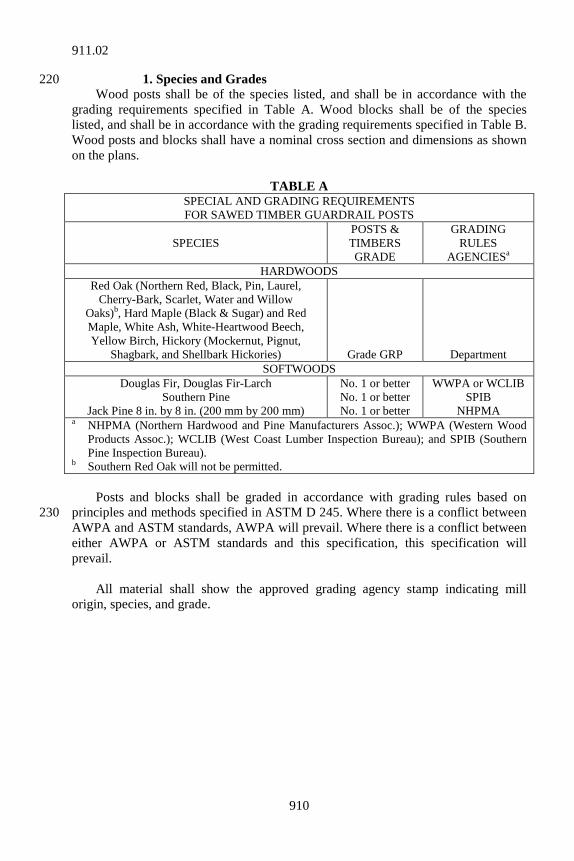
910
1. Species and Grades 220 Wood posts shall be of the species listed, and shall be in accordance with the grading requirements specified in Table A. Wood blocks shall be of the species listed, and shall be in accordance with the grading requirements specified in Table B. Wood posts and blocks shall have a nominal cross section and dimensions as shown on the plans.
TABLE A SPECIAL AND GRADING REQUIREMENTS FOR SAWED TIMBER GUARDRAIL POSTS
SPECIES POSTS & TIMBERS GRADE
GRADING RULES
AGENCIESa HARDWOODS
Red Oak (Northern Red, Black, Pin, Laurel, Cherry-Bark, Scarlet, Water and Willow
Oaks)b, Hard Maple (Black & Sugar) and Red Maple, White Ash, White-Heartwood Beech, Yellow Birch, Hickory (Mockernut, Pignut,
Shagbark, and Shellbark Hickories)
Grade GRP
Department SOFTWOODS
Douglas Fir, Douglas Fir-Larch Southern Pine
Jack Pine 8 in. by 8 in. (200 mm by 200 mm)
No. 1 or better No. 1 or better No. 1 or better
WWPA or WCLIB SPIB
NHPMA a NHPMA (Northern Hardwood and Pine Manufacturers Assoc.); WWPA (Western Wood
Products Assoc.); WCLIB (West Coast Lumber Inspection Bureau); and SPIB (Southern Pine Inspection Bureau).
b Southern Red Oak will not be permitted. Posts and blocks shall be graded in accordance with grading rules based on principles and methods specified in ASTM D 245. Where there is a conflict between 230 AWPA and ASTM standards, AWPA will prevail. Where there is a conflict between either AWPA or ASTM standards and this specification, this specification will prevail. All material shall show the approved grading agency stamp indicating mill origin, species, and grade.
911.02
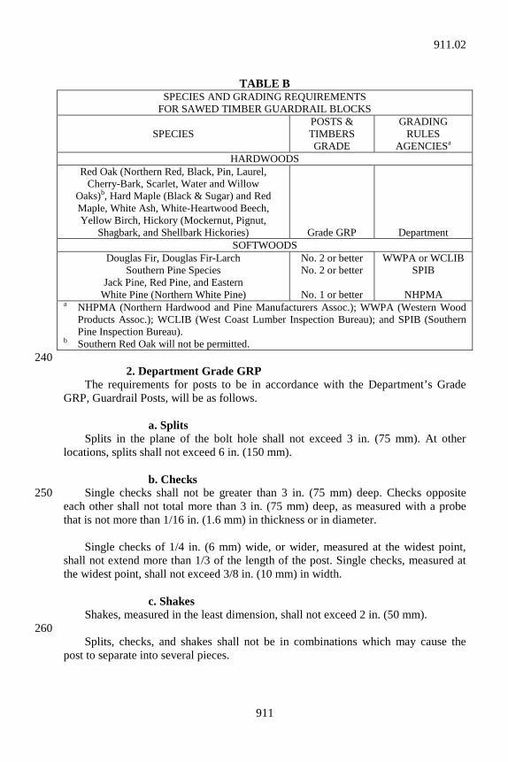
911
TABLE B
SPECIES AND GRADING REQUIREMENTS FOR SAWED TIMBER GUARDRAIL BLOCKS
SPECIES POSTS & TIMBERS GRADE
GRADING RULES
AGENCIESa HARDWOODS
Red Oak (Northern Red, Black, Pin, Laurel, Cherry-Bark, Scarlet, Water and Willow
Oaks)b, Hard Maple (Black & Sugar) and Red Maple, White Ash, White-Heartwood Beech, Yellow Birch, Hickory (Mockernut, Pignut,
Shagbark, and Shellbark Hickories)
Grade GRP
Department SOFTWOODS
Douglas Fir, Douglas Fir-Larch Southern Pine Species
Jack Pine, Red Pine, and Eastern White Pine (Northern White Pine)
No. 2 or better No. 2 or better
No. 1 or better
WWPA or WCLIB SPIB
NHPMA
a NHPMA (Northern Hardwood and Pine Manufacturers Assoc.); WWPA (Western Wood Products Assoc.); WCLIB (West Coast Lumber Inspection Bureau); and SPIB (Southern Pine Inspection Bureau).
b Southern Red Oak will not be permitted. 240 2. Department Grade GRP The requirements for posts to be in accordance with the Department’s Grade GRP, Guardrail Posts, will be as follows. a. Splits Splits in the plane of the bolt hole shall not exceed 3 in. (75 mm). At other locations, splits shall not exceed 6 in. (150 mm). b. Checks Single checks shall not be greater than 3 in. (75 mm) deep. Checks opposite 250 each other shall not total more than 3 in. (75 mm) deep, as measured with a probe that is not more than 1/16 in. (1.6 mm) in thickness or in diameter. Single checks of 1/4 in. (6 mm) wide, or wider, measured at the widest point, shall not extend more than 1/3 of the length of the post. Single checks, measured at the widest point, shall not exceed 3/8 in. (10 mm) in width. c. Shakes Shakes, measured in the least dimension, shall not exceed 2 in. (50 mm). 260 Splits, checks, and shakes shall not be in combinations which may cause the post to separate into several pieces.
911.02
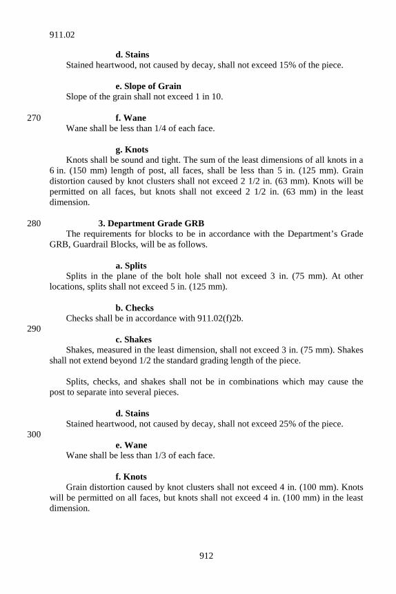
912
d. Stains Stained heartwood, not caused by decay, shall not exceed 15% of the piece. e. Slope of Grain Slope of the grain shall not exceed 1 in 10. f. Wane 270 Wane shall be less than 1/4 of each face. g. Knots Knots shall be sound and tight. The sum of the least dimensions of all knots in a 6 in. (150 mm) length of post, all faces, shall be less than 5 in. (125 mm). Grain distortion caused by knot clusters shall not exceed 2 1/2 in. (63 mm). Knots will be permitted on all faces, but knots shall not exceed 2 1/2 in. (63 mm) in the least dimension. 3. Department Grade GRB 280 The requirements for blocks to be in accordance with the Department’s Grade GRB, Guardrail Blocks, will be as follows. a. Splits Splits in the plane of the bolt hole shall not exceed 3 in. (75 mm). At other locations, splits shall not exceed 5 in. (125 mm). b. Checks Checks shall be in accordance with 911.02(f)2b. 290 c. Shakes Shakes, measured in the least dimension, shall not exceed 3 in. (75 mm). Shakes shall not extend beyond 1/2 the standard grading length of the piece. Splits, checks, and shakes shall not be in combinations which may cause the post to separate into several pieces. d. Stains Stained heartwood, not caused by decay, shall not exceed 25% of the piece. 300 e. Wane Wane shall be less than 1/3 of each face. f. Knots Grain distortion caused by knot clusters shall not exceed 4 in. (100 mm). Knots will be permitted on all faces, but knots shall not exceed 4 in. (100 mm) in the least dimension.
911.02
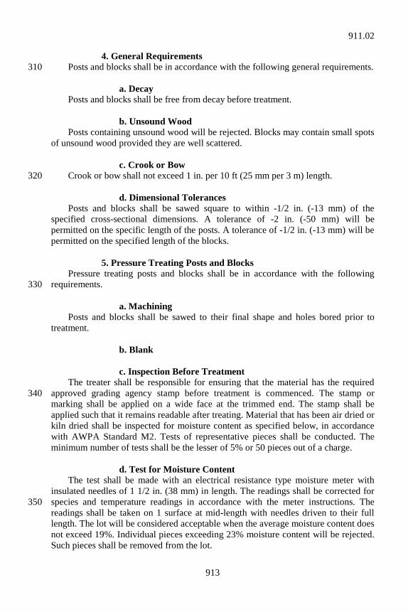
913
4. General Requirements Posts and blocks shall be in accordance with the following general requirements. 310 a. Decay Posts and blocks shall be free from decay before treatment. b. Unsound Wood Posts containing unsound wood will be rejected. Blocks may contain small spots of unsound wood provided they are well scattered. c. Crook or Bow Crook or bow shall not exceed 1 in. per 10 ft (25 mm per 3 m) length. 320 d. Dimensional Tolerances Posts and blocks shall be sawed square to within -1/2 in. (-13 mm) of the specified cross-sectional dimensions. A tolerance of -2 in. (-50 mm) will be permitted on the specific length of the posts. A tolerance of -1/2 in. (-13 mm) will be permitted on the specified length of the blocks. 5. Pressure Treating Posts and Blocks Pressure treating posts and blocks shall be in accordance with the following requirements. 330 a. Machining Posts and blocks shall be sawed to their final shape and holes bored prior to treatment. b. Blank c. Inspection Before Treatment The treater shall be responsible for ensuring that the material has the required approved grading agency stamp before treatment is commenced. The stamp or 340 marking shall be applied on a wide face at the trimmed end. The stamp shall be applied such that it remains readable after treating. Material that has been air dried or kiln dried shall be inspected for moisture content as specified below, in accordance with AWPA Standard M2. Tests of representative pieces shall be conducted. The minimum number of tests shall be the lesser of 5% or 50 pieces out of a charge. d. Test for Moisture Content The test shall be made with an electrical resistance type moisture meter with insulated needles of 1 1/2 in. (38 mm) in length. The readings shall be corrected for species and temperature readings in accordance with the meter instructions. The 350 readings shall be taken on 1 surface at mid-length with needles driven to their full length. The lot will be considered acceptable when the average moisture content does not exceed 19%. Individual pieces exceeding 23% moisture content will be rejected. Such pieces shall be removed from the lot.
911.02
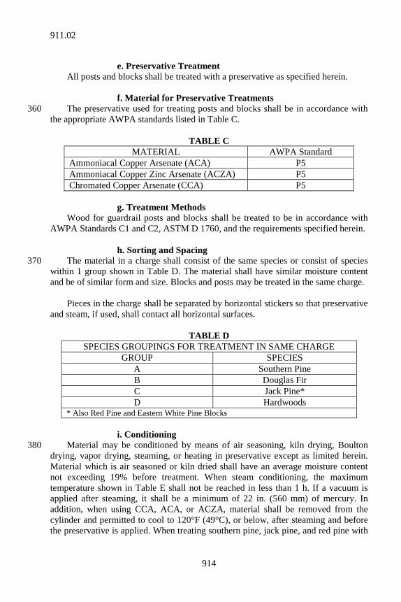
914
e. Preservative Treatment All posts and blocks shall be treated with a preservative as specified herein. f. Material for Preservative Treatments The preservative used for treating posts and blocks shall be in accordance with 360 the appropriate AWPA standards listed in Table C.
TABLE C MATERIAL AWPA Standard
Ammoniacal Copper Arsenate (ACA) P5 Ammoniacal Copper Zinc Arsenate (ACZA) P5 Chromated Copper Arsenate (CCA) P5
g. Treatment Methods Wood for guardrail posts and blocks shall be treated to be in accordance with AWPA Standards C1 and C2, ASTM D 1760, and the requirements specified herein. h. Sorting and Spacing The material in a charge shall consist of the same species or consist of species 370 within 1 group shown in Table D. The material shall have similar moisture content and be of similar form and size. Blocks and posts may be treated in the same charge. Pieces in the charge shall be separated by horizontal stickers so that preservative and steam, if used, shall contact all horizontal surfaces.
TABLE D SPECIES GROUPINGS FOR TREATMENT IN SAME CHARGE
GROUP SPECIES A Southern Pine B Douglas Fir C Jack Pine* D Hardwoods
* Also Red Pine and Eastern White Pine Blocks i. Conditioning Material may be conditioned by means of air seasoning, kiln drying, Boulton 380 drying, vapor drying, steaming, or heating in preservative except as limited herein. Material which is air seasoned or kiln dried shall have an average moisture content not exceeding 19% before treatment. When steam conditioning, the maximum temperature shown in Table E shall not be reached in less than 1 h. If a vacuum is applied after steaming, it shall be a minimum of 22 in. (560 mm) of mercury. In addition, when using CCA, ACA, or ACZA, material shall be removed from the cylinder and permitted to cool to 120°F (49°C), or below, after steaming and before the preservative is applied. When treating southern pine, jack pine, and red pine with
911.02
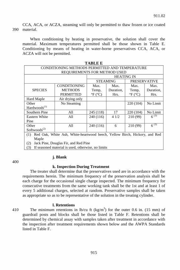
915
CCA, ACA, or ACZA, steaming will only be permitted to thaw frozen or ice coated material. 390 When conditioning by heating in preservative, the solution shall cover the material. Maximum temperatures permitted shall be those shown in Table E. Conditioning by means of heating in water-borne preservatives CCA, ACA, or ACZA will not be permitted.
TABLE E CONDITIONING METHODS PERMITTED AND TEMPERATURE
REQUIREMENTS FOR METHOD USED
HEATING IN STEAMING PRESERVATIVE
SPECIES CONDITIONING
METHODS PERMITTED
Max. Temp, °F (°C)
Max. Duration,
Hrs.
Max. Temp, °F (°C)
Max. Duration,
Hrs. Hard Maple Air drying only Other Hardwoods(1)
No Steaming 220 (104) No Limit
Southern Pine All 245 (118) 17 220 (104) No Limit Eastern White Pine
All 240 (116) 4 1/2 210 (99) 6 (3)
Other Softwoods(2)
All 240 (116) 6 210 (99) 6 (3)
(1) Red Oak, White Ash, White-heartwood beech, Yellow Birch, Hickory, and Red Maple
(2) Jack Pine, Douglas Fir, and Red Pine (3) If seasoned material is used, otherwise, no limits
j. Blank 400 k. Inspection During Treatment The treater shall determine that the preservatives used are in accordance with the requirements herein. The minimum frequency of the preservation analysis shall be each charge for the occasional single charge inspected. The minimum frequency for consecutive treatments from the same working tank shall be the 1st and at least 1 of every 5 additional charges, selected at random. Preservative samples shall be taken as appropriate so as to be representative of the solution in the treating cylinder. l. Retentions The minimum retentions in lb/cu ft (kg/m3) for the outer 0.6 in. (15 mm) of 410 guardrail posts and blocks shall be those listed in Table F. Retentions shall be determined by chemical assay with samples taken after treatment in accordance with the inspection after treatment requirements shown below and the AWPA Standards listed in Table F.
911.02
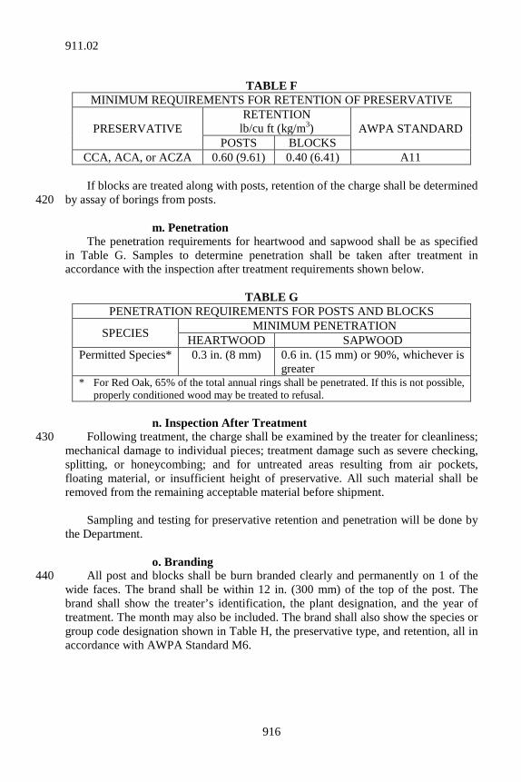
916
TABLE F
MINIMUM REQUIREMENTS FOR RETENTION OF PRESERVATIVE
PRESERVATIVE RETENTION
lb/cu ft (kg/m3) AWPA STANDARD POSTS BLOCKS
CCA, ACA, or ACZA 0.60 (9.61) 0.40 (6.41) A11 If blocks are treated along with posts, retention of the charge shall be determined by assay of borings from posts. 420 m. Penetration The penetration requirements for heartwood and sapwood shall be as specified in Table G. Samples to determine penetration shall be taken after treatment in accordance with the inspection after treatment requirements shown below.
TABLE G PENETRATION REQUIREMENTS FOR POSTS AND BLOCKS
SPECIES MINIMUM PENETRATION HEARTWOOD SAPWOOD
Permitted Species* 0.3 in. (8 mm) 0.6 in. (15 mm) or 90%, whichever is greater
* For Red Oak, 65% of the total annual rings shall be penetrated. If this is not possible, properly conditioned wood may be treated to refusal.
n. Inspection After Treatment Following treatment, the charge shall be examined by the treater for cleanliness; 430 mechanical damage to individual pieces; treatment damage such as severe checking, splitting, or honeycombing; and for untreated areas resulting from air pockets, floating material, or insufficient height of preservative. All such material shall be removed from the remaining acceptable material before shipment. Sampling and testing for preservative retention and penetration will be done by the Department. o. Branding All post and blocks shall be burn branded clearly and permanently on 1 of the 440 wide faces. The brand shall be within 12 in. (300 mm) of the top of the post. The brand shall show the treater’s identification, the plant designation, and the year of treatment. The month may also be included. The brand shall also show the species or group code designation shown in Table H, the preservative type, and retention, all in accordance with AWPA Standard M6.
911.02
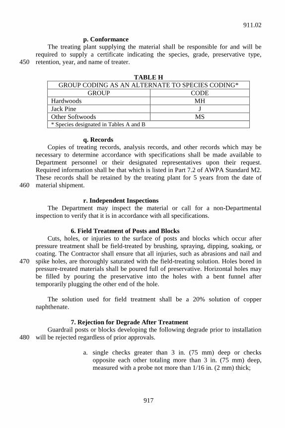
917
p. Conformance The treating plant supplying the material shall be responsible for and will be required to supply a certificate indicating the species, grade, preservative type, retention, year, and name of treater. 450
TABLE H GROUP CODING AS AN ALTERNATE TO SPECIES CODING*
GROUP CODE Hardwoods MH Jack Pine J Other Softwoods MS * Species designated in Tables A and B
q. Records Copies of treating records, analysis records, and other records which may be necessary to determine accordance with specifications shall be made available to Department personnel or their designated representatives upon their request. Required information shall be that which is listed in Part 7.2 of AWPA Standard M2. These records shall be retained by the treating plant for 5 years from the date of material shipment. 460 r. Independent Inspections The Department may inspect the material or call for a non-Departmental inspection to verify that it is in accordance with all specifications. 6. Field Treatment of Posts and Blocks Cuts, holes, or injuries to the surface of posts and blocks which occur after pressure treatment shall be field-treated by brushing, spraying, dipping, soaking, or coating. The Contractor shall ensure that all injuries, such as abrasions and nail and spike holes, are thoroughly saturated with the field-treating solution. Holes bored in 470 pressure-treated materials shall be poured full of preservative. Horizontal holes may be filled by pouring the preservative into the holes with a bent funnel after temporarily plugging the other end of the hole. The solution used for field treatment shall be a 20% solution of copper naphthenate. 7. Rejection for Degrade After Treatment Guardrail posts or blocks developing the following degrade prior to installation will be rejected regardless of prior approvals. 480 a. single checks greater than 3 in. (75 mm) deep or checks
opposite each other totaling more than 3 in. (75 mm) deep, measured with a probe not more than 1/16 in. (2 mm) thick;
911.02
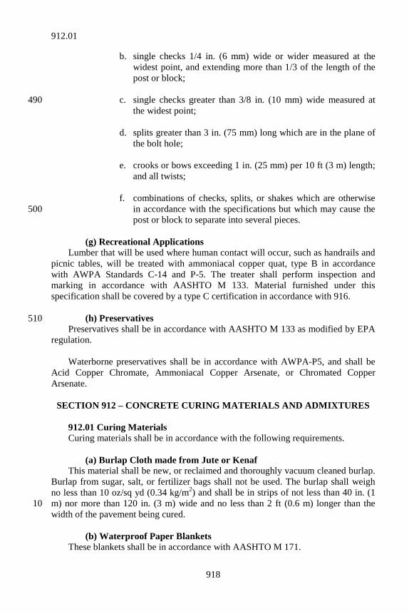
918
b. single checks 1/4 in. (6 mm) wide or wider measured at the widest point, and extending more than 1/3 of the length of the post or block;
c. single checks greater than 3/8 in. (10 mm) wide measured at 490
the widest point; d. splits greater than 3 in. (75 mm) long which are in the plane of
the bolt hole; e. crooks or bows exceeding 1 in. (25 mm) per 10 ft (3 m) length;
and all twists; f. combinations of checks, splits, or shakes which are otherwise
in accordance with the specifications but which may cause the 500 post or block to separate into several pieces.
(g) Recreational Applications Lumber that will be used where human contact will occur, such as handrails and picnic tables, will be treated with ammoniacal copper quat, type B in accordance with AWPA Standards C-14 and P-5. The treater shall perform inspection and marking in accordance with AASHTO M 133. Material furnished under this specification shall be covered by a type C certification in accordance with 916. (h) Preservatives 510 Preservatives shall be in accordance with AASHTO M 133 as modified by EPA regulation. Waterborne preservatives shall be in accordance with AWPA-P5, and shall be Acid Copper Chromate, Ammoniacal Copper Arsenate, or Chromated Copper Arsenate.
SECTION 912 – CONCRETE CURING MATERIALS AND ADMIXTURES 912.01 Curing Materials Curing materials shall be in accordance with the following requirements. (a) Burlap Cloth made from Jute or Kenaf This material shall be new, or reclaimed and thoroughly vacuum cleaned burlap. Burlap from sugar, salt, or fertilizer bags shall not be used. The burlap shall weigh no less than 10 oz/sq yd (0.34 kg/m2) and shall be in strips of not less than 40 in. (1 m) nor more than 120 in. (3 m) wide and no less than 2 ft (0.6 m) longer than the 10 width of the pavement being cured. (b) Waterproof Paper Blankets These blankets shall be in accordance with AASHTO M 171.
912.01
919
(c) White Polyethylene Sheeting, Film The sheeting shall be in accordance with AASHTO M 171. (d) White Burlap Polyethylene Sheet These sheets shall be in accordance with AASHTO M 171. 20 (e) Liquid Membrane Forming Compounds These compounds shall be in accordance with AASHTO M 148, type 2, except the drying time requirement will be determined on a glass surface. (f) Polyethylene Film The sheeting shall be in accordance with AASHTO M 171. 912.02 Curing-Sealing Materials Curing-sealing materials are single application curing and sealing products for 30 portland cement concrete. A list of approved Curing-Sealing Materials will be maintained by the Department. The list will identify pre-approved products, specify the manufacturer and product designation, and include application instructions. In order to have a product added to the list of approved Curing-Sealing Materials, the manufacturer shall furnish to the Office of Materials Management a type A certification in accordance with 916. Such certification shall state that the product is in accordance with the requirements of NCHRP 244 Series IV Southern 40 Climate Weathering Test, and AASHTO M 148 Type 1. (a) The certification shall be in accordance with the applicable
requirements of 916, and shall include a dated test report. The test report shall substantiate full compliance with the specifications and establish when the testing was started. Test reports older than 7 years on January 1st of the approval year will not be accepted.
(b) If irregularities are found in the results required for such certification,
copies of the original data may be required prior to reconsideration of 50 the certification.
(c) Tests must be conducted by a state highway agency testing laboratory
or a testing laboratory regularly inspected by CCRL. Proof of such inspection shall be furnished with the test report.
After a product has been approved, it will be added to the list of approved and/or Prequalified Materials. The product will remain on the list until test results on file are 7 years old, provided that there are no changes in raw materials, formulation, or procedures for manufacture. Results more than 7 years old or products in which there 60
912.02
920
has been a change in raw materials, formulation, or procedures for manufacture shall be recertified in order to remain on the list. A curing-sealing material that performs unsatisfactorily in the field will be removed from the approved list. 912.03 Admixtures for Use in Concrete Admixtures for use in PCC shall be selected from the Department’s list of approved Admixtures for PCC. An admixture may be added to the approved list by completing the requirements in ITM 806, Procedure D. Admixtures containing 70 chloride added as an ingredient of manufacture are unacceptable. (a) Air Entraining Admixtures Air entraining admixtures are materials to be added to PCC mixtures at the mixer for the purpose of entraining air. (b) Chemical Admixtures for Concrete Chemical admixtures are materials to be added to PCC mixtures at the mixer for the purpose or purposes indicated below. 80 1. Type A Type A is a water reducing admixture that reduces the quantity of mixing water required to produce concrete of a given consistency. 2. Type B Type B is a retarding admixture that retards the setting of concrete. 3. Type C Type C is an accelerating admixture that accelerates the setting and early strength development of concrete. 90 4. Type D Type D is a water reducing and retarding admixture that reduces the quantity of mixing water required to produce concrete of a given consistency and retards the setting of concrete. 5. Type E Type E is a water reducing and accelerating admixture that reduces the quantity of mixing water required to produce concrete of a given consistency and accelerates the setting and early strength development of concrete. 100 6. Type F Type F is a high range water reducing admixture, HRWR, that reduces the quantity of mixing water required to produce concrete of a given consistency by 12% or greater.
912.03
921
7. Type G Type G is a high range water reducing and retarding admixture, HRWRR, that reduces the quantity of mixing water required to produce concrete of a given consistency by 12% or greater, and retards the setting of concrete. 110 8. High Range Water Reducing Admixture System HRWR admixture system is a combination of admixtures that act as a type F mixture within a concrete mixture. The system consists of chemical admixtures and an air entraining admixture. One of the components shall be a type F admixture. Components shall be in accordance with 912.03 for their respective types. 9. High Range Water Reducing and Retarding Admixture System HRWRR admixture system is a combination of admixtures that act as a type G admixture within a concrete mixture. The system consists of chemical admixtures 120 and an air entraining admixture. One of the components shall be a type F or a type G admixture. One of the components shall retard the setting of the concrete. Components shall be in accordance with 912.03 for their respective types. (c) Test Report Testing shall be performed by a recognized laboratory in accordance with ITM 806. 1. Air entraining admixtures shall be in accordance with AASHTO
M 154. 130 2. Chemical admixtures shall be in accordance with AASHTO M 194
for their respective types. 3. Test reports shall not be more than 5 years old on January 1st of
the approval year. New submittals of test reports more than 5 years old will be accepted, if all subsequent 5 year limited retest reports, are submitted. Subsequent limited retest results shall comply with the dating and age requirements specified above and shall include the following tests as a minimum requirement for compliance. 140
a. infrared analysis, residue by oven drying, and specific gravity; b. water content and time of setting; c. flexural strength at 3, 7, and 28 days; d. relative durability.
912.03
922
912.04 Latex Modifiers 150 The latex modifiers are an admixture to be added to the concrete mixture at the continuous mixer. The latex shall be 1 of the latex modifiers in the list of approved Admixtures for Portland Cement Concrete. The formulated latex admixture shall be a non-toxic, film forming, polymeric emulsion in water to which all stabilizers have been added at the point of manufacture and shall be homogeneous and uniform in composition. A type B certification shall be furnished in accordance with 916. Physical properties of the latex modifier shall be in accordance with the 160 following: Polymer Type .................................................................... Styrene Butadiene Stabilizers .................................................. Anionic and Nonionic Surfactants Anitfoaming Agent ..................................................... Polydimethyl Siloxane Percent Solids, % by Mass ...................................................... 46.0 Minimum Mass Per Gallon (Liter) ....................................... 8.4 lb (1.0 kg) at Minimum pH (as shipped) .................................................................................. 9.0-11.0 Freeze/Thaw Stability .................................................. 5 Cycles, -15° to 25°C Shelf Life ........................................................................... 2 Years, Minimum 170 Color ...................................................................................................... White 912.05 Foaming Agent Foaming agents used in making preformed foam for cellular concrete grout shall be in accordance with ASTM C 869. A type C certification shall be furnished in accordance with 916.
SECTION 913 – SOIL TREATMENT MATERIALS 913.01 Water Water used in mixing or curing shall be reasonably clean and free of oil, salt, acid, alkali, sugar, vegetable, or other substance injurious to the finished product. Water will be tested in accordance with AASHTO T 26. Water shall be in accordance with the requirements as follows. (a) pH .................................................................................................... 6 to 8 (b) Chloride Ions ............................................................... less than 300 ppm 10 (c) Sulphate (SO4) ............................................................. less than 500 ppm (d) Total Solids ................................................................ less than 1500 ppm In addition, water containing algae will be unacceptable for use in concrete. Water known to be of potable quality may be used without test. Where the source of water is relatively shallow, the intake shall be so enclosed as to exclude silt, mud, grass, or other foreign materials.
912.04
923
913.02 Calcium Chloride Calcium chloride shall be in accordance with AASHTO M 144 and shall be: 20 (a) Type S, grade 1, class A (b) Type S, grade 3, class A or B (c) Type L 913.03 Sodium Chloride Sodium chloride shall be in accordance with AASHTO M 143. Rock salt shall be used for de-icing purposes. Either rock salt or evaporated salt may be used for 30 stabilization. 913.04 Lime Lime shall be a hydrated lime when used in masonry or a hydrated lime, quicklime, or lime by-product when used for soil modification. (a) Hydrated Lime for Masonry Hydrated lime used in masonry shall be in accordance with ASTM C 207, Type N. 40 (b) Lime for Soil Modification Hydrated lime, quicklime, or lime by-product used for soil modification shall be approved in accordance with ITM 806, Procedure P and shall meet the following requirements. 1. Hydrated Lime and Quicklime Hydrated lime and quicklime shall be in accordance with AASHTO M 216. 2. Lime By-Products Lime by-products shall be hydrated lime or quicklime by-products in accordance 50 with ASTM C 25 having the following requirements. a. The lime by-products shall contain a minimum of 60% total
calcium and magnesium oxides (non-volatile basis). b. Available calcium hydroxide plus magnesium oxide calculated
as calcium hydroxide shall be a minimum of 30%. c. Sieve analysis shall be performed in accordance with ASTM
C 110. The lime by-products gradation shall be as follows: 60 Sieve % Retained (Max) No. 4 (4.75 mm) 5
913.04
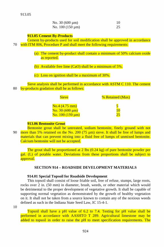
924
No. 30 (600 µm) 10 No. 100 (150 µm) 25 913.05 Cement By-Products Cement by-products used for soil modification shall be approved in accordance with ITM 806, Procedure P and shall meet the following requirements: 70 (a) The cement by-product shall contain a minimum of 50% calcium oxide
as reported. (b) Available free lime (CaO) shall be a minimum of 5%. (c) Loss on ignition shall be a maximum of 30%. Sieve analysis shall be performed in accordance with ASTM C 110. The cement by-products gradation shall be as follows: 80 Sieve % Retained (Max) No.4 (4.75 mm) 5 No. 30 (600 μm) 10 No. 100 (150 μm) 25 913.06 Bentonite Grout Bentonite grout shall be untreated, sodium bentonite, finely ground with not more than 5% retained on the No. 200 (75 µm) sieve. It shall be free of lumps and 90 materials that can prevent mixing into a fluid free of lumps of unmixed bentonite. Calcium bentonite will not be accepted. The grout shall be proportioned at 2 lbs (0.24 kg) of pure bentonite powder per gal. (L) of potable water. Deviations from these proportions shall be subject to approval.
SECTION 914 – ROADSIDE DEVELOPMENT MATERIALS 914.01 Special Topsoil for Roadside Development This topsoil shall consist of loose friable soil, free of refuse, stumps, large roots, rocks over 2 in. (50 mm) in diameter, brush, weeds, or other material which would be detrimental to the proper development of vegetative growth. It shall be capable of supporting normal vegetation as demonstrated by the growth of healthy vegetation on it. It shall not be taken from a source known to contain any of the noxious weeds defined as such in the Indiana State Seed Law, IC 15-4-1. 10 Topsoil shall have a pH value of 6.2 to 7.4. Testing for pH value shall be performed in accordance with AASHTO T 289. Agricultural limestone may be added to topsoil in order to raise the pH to meet specification requirements. The
913.05
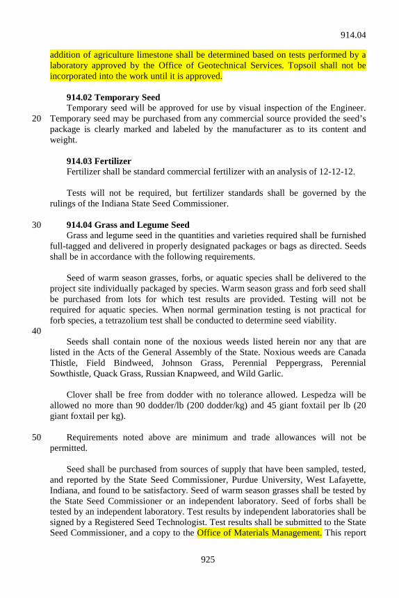
925
addition of agriculture limestone shall be determined based on tests performed by a laboratory approved by the Office of Geotechnical Services. Topsoil shall not be incorporated into the work until it is approved. 914.02 Temporary Seed Temporary seed will be approved for use by visual inspection of the Engineer. Temporary seed may be purchased from any commercial source provided the seed’s 20 package is clearly marked and labeled by the manufacturer as to its content and weight. 914.03 Fertilizer Fertilizer shall be standard commercial fertilizer with an analysis of 12-12-12. Tests will not be required, but fertilizer standards shall be governed by the rulings of the Indiana State Seed Commissioner. 914.04 Grass and Legume Seed 30 Grass and legume seed in the quantities and varieties required shall be furnished full-tagged and delivered in properly designated packages or bags as directed. Seeds shall be in accordance with the following requirements. Seed of warm season grasses, forbs, or aquatic species shall be delivered to the project site individually packaged by species. Warm season grass and forb seed shall be purchased from lots for which test results are provided. Testing will not be required for aquatic species. When normal germination testing is not practical for forb species, a tetrazolium test shall be conducted to determine seed viability. 40 Seeds shall contain none of the noxious weeds listed herein nor any that are listed in the Acts of the General Assembly of the State. Noxious weeds are Canada Thistle, Field Bindweed, Johnson Grass, Perennial Peppergrass, Perennial Sowthistle, Quack Grass, Russian Knapweed, and Wild Garlic. Clover shall be free from dodder with no tolerance allowed. Lespedza will be allowed no more than 90 dodder/lb (200 dodder/kg) and 45 giant foxtail per lb (20 giant foxtail per kg). Requirements noted above are minimum and trade allowances will not be 50 permitted. Seed shall be purchased from sources of supply that have been sampled, tested, and reported by the State Seed Commissioner, Purdue University, West Lafayette, Indiana, and found to be satisfactory. Seed of warm season grasses shall be tested by the State Seed Commissioner or an independent laboratory. Seed of forbs shall be tested by an independent laboratory. Test results by independent laboratories shall be signed by a Registered Seed Technologist. Test results shall be submitted to the State Seed Commissioner, and a copy to the Office of Materials Management. This report
914.04
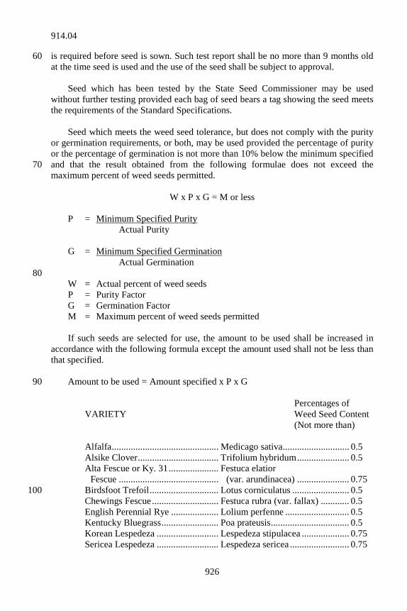
926
is required before seed is sown. Such test report shall be no more than 9 months old 60 at the time seed is used and the use of the seed shall be subject to approval. Seed which has been tested by the State Seed Commissioner may be used without further testing provided each bag of seed bears a tag showing the seed meets the requirements of the Standard Specifications. Seed which meets the weed seed tolerance, but does not comply with the purity or germination requirements, or both, may be used provided the percentage of purity or the percentage of germination is not more than 10% below the minimum specified and that the result obtained from the following formulae does not exceed the 70 maximum percent of weed seeds permitted.
W x P x G = M or less P = Minimum Specified Purity Actual Purity G = Minimum Specified Germination Actual Germination 80 W = Actual percent of weed seeds P = Purity Factor G = Germination Factor M = Maximum percent of weed seeds permitted If such seeds are selected for use, the amount to be used shall be increased in accordance with the following formula except the amount used shall not be less than that specified. Amount to be used = Amount specified x P x G 90 Percentages of VARIETY Weed Seed Content (Not more than) Alfalfa ............................................. Medicago sativa ............................ 0.5 Alsike Clover .................................. Trifolium hybridum ...................... 0.5 Alta Fescue or Ky. 31 ..................... Festuca elatior Fescue .......................................... (var. arundinacea) ...................... 0.75 Birdsfoot Trefoil ............................. Lotus corniculatus ........................ 0.5 100 Chewings Fescue ............................ Festuca rubra (var. fallax) ............ 0.5 English Perennial Rye .................... Lolium perfenne ........................... 0.5 Kentucky Bluegrass ........................ Poa prateusis ................................. 0.5 Korean Lespedeza .......................... Lespedeza stipulacea .................... 0.75 Sericea Lespedeza .......................... Lespedeza sericea ......................... 0.75
914.04
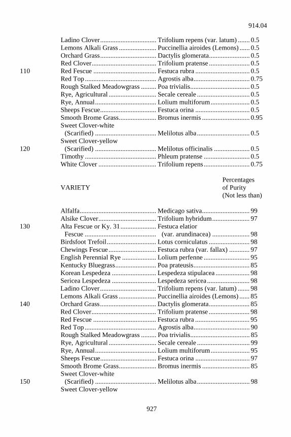
927
Ladino Clover ................................. Trifolium repens (var. latum) ....... 0.5 Lemons Alkali Grass ...................... Puccinellia airoides (Lemons) ...... 0.5 Orchard Grass ................................. Dactylis glomerata ........................ 0.5 Red Clover ...................................... Trifolium pratense ........................ 0.5 Red Fescue ..................................... Festuca rubra ................................ 0.5 110 Red Top .......................................... Agrostis alba ................................. 0.75 Rough Stalked Meadowgrass ......... Poa trivialis ................................... 0.5 Rye, Agricultural ............................ Secale cereale ............................... 0.5 Rye, Annual .................................... Lolium multiforum ....................... 0.5 Sheeps Fescue ................................. Festuca orina ................................ 0.5 Smooth Brome Grass ...................... Bromus inermis ............................ 0.95 Sweet Clover-white (Scarified) .................................... Melilotus alba ............................... 0.5 Sweet Clover-yellow (Scarified) .................................... Melilotus officinalis ..................... 0.5 120 Timothy .......................................... Phleum pratense ........................... 0.5 White Clover .................................. Trifolium repens ........................... 0.75 Percentages VARIETY of Purity (Not less than) Alfalfa ............................................. Medicago sativa ............................ 99 Alsike Clover .................................. Trifolium hybridum ...................... 97 Alta Fescue or Ky. 31 ..................... Festuca elatior 130 Fescue .......................................... (var. arundinacea) ...................... 98 Birdsfoot Trefoil ............................. Lotus corniculatus ........................ 98 Chewings Fescue ............................ Festuca rubra (var. fallax) ............ 97 English Perennial Rye .................... Lolium perfenne ........................... 95 Kentucky Bluegrass ........................ Poa prateusis ................................. 85 Korean Lespedeza .......................... Lespedeza stipulacea .................... 98 Sericea Lespedeza .......................... Lespedeza sericea ......................... 98 Ladino Clover ................................. Trifolium repens (var. latum) ....... 98 Lemons Alkali Grass ...................... Puccinellia airoides (Lemons) ...... 85 Orchard Grass ................................. Dactylis glomerata ........................ 85 140 Red Clover ...................................... Trifolium pratense ........................ 98 Red Fescue ..................................... Festuca rubra ................................ 95 Red Top .......................................... Agrostis alba ................................. 90 Rough Stalked Meadowgrass ......... Poa trivialis ................................... 85 Rye, Agricultural ............................ Secale cereale ............................... 99 Rye, Annual .................................... Lolium multiforum ....................... 95 Sheeps Fescue ................................. Festuca orina ................................ 97 Smooth Brome Grass ...................... Bromus inermis ............................ 85 Sweet Clover-white (Scarified) .................................... Melilotus alba ............................... 98 150 Sweet Clover-yellow
914.04
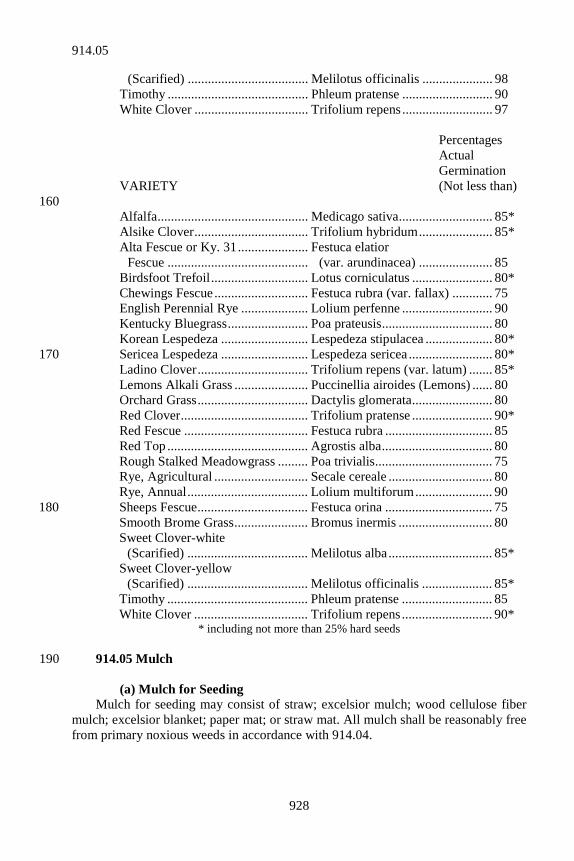
928
(Scarified) .................................... Melilotus officinalis ..................... 98 Timothy .......................................... Phleum pratense ........................... 90 White Clover .................................. Trifolium repens ........................... 97 Percentages Actual Germination VARIETY (Not less than) 160 Alfalfa ............................................. Medicago sativa ............................ 85* Alsike Clover .................................. Trifolium hybridum ...................... 85* Alta Fescue or Ky. 31 ..................... Festuca elatior Fescue .......................................... (var. arundinacea) ...................... 85 Birdsfoot Trefoil ............................. Lotus corniculatus ........................ 80* Chewings Fescue ............................ Festuca rubra (var. fallax) ............ 75 English Perennial Rye .................... Lolium perfenne ........................... 90 Kentucky Bluegrass ........................ Poa prateusis ................................. 80 Korean Lespedeza .......................... Lespedeza stipulacea .................... 80* Sericea Lespedeza .......................... Lespedeza sericea ......................... 80* 170 Ladino Clover ................................. Trifolium repens (var. latum) ....... 85* Lemons Alkali Grass ...................... Puccinellia airoides (Lemons) ...... 80 Orchard Grass ................................. Dactylis glomerata ........................ 80 Red Clover ...................................... Trifolium pratense ........................ 90* Red Fescue ..................................... Festuca rubra ................................ 85 Red Top .......................................... Agrostis alba ................................. 80 Rough Stalked Meadowgrass ......... Poa trivialis ................................... 75 Rye, Agricultural ............................ Secale cereale ............................... 80 Rye, Annual .................................... Lolium multiforum ....................... 90 Sheeps Fescue ................................. Festuca orina ................................ 75 180 Smooth Brome Grass ...................... Bromus inermis ............................ 80 Sweet Clover-white (Scarified) .................................... Melilotus alba ............................... 85* Sweet Clover-yellow (Scarified) .................................... Melilotus officinalis ..................... 85* Timothy .......................................... Phleum pratense ........................... 85 White Clover .................................. Trifolium repens ........................... 90*
* including not more than 25% hard seeds 914.05 Mulch 190 (a) Mulch for Seeding Mulch for seeding may consist of straw; excelsior mulch; wood cellulose fiber mulch; excelsior blanket; paper mat; or straw mat. All mulch shall be reasonably free from primary noxious weeds in accordance with 914.04.
914.05
929
1. Excelsior Mulch Excelsior mulch shall consist of wood fibers cut from sound green timber. The average length of the fibers shall be 4 in. to 6 in. (100 mm to 150 mm). The cut shall be made in such a manner as to provide maximum strength of fiber, but at a slight 200 angle to the natural grain of the wood so as to cause splintering of the fibers when weathering in order to provide adherence to each other and to the soil. 2. Wood Cellulose Fiber Wood cellulose fiber mulch shall be made from wood chip particles manufactured articularly for discharging uniformly on the ground surface when disbursed by a hydraulic water sprayer. It shall remain in uniform suspension in water under agitation and blend with grass seed, and fertilizer when permitted, to form a homogeneous slurry. The mulch fibers shall intertwine physically to form a strong moisture holding mat on the ground surface. The mulch shall be heat 210 processed so as to contain no germination or growth inhibiting factors. It shall be non-toxic and colored green. The percent of moisture content shall be determined in accordance with 621.14(c), except material containing more than 15% will be rejected. The ash content shall not exceed 1.5%. One hundred grams of oven dried material saturated in water, drained, and weighed shall hold a minimum of 1,000 grams of water. 3. Excelsior Blanket Excelsior blanket shall consist of a machine produced mat of wood excelsior with 80% of the fibers to be 6 in. (150 mm) or longer. The wood from which the 220 excelsior is cut shall be properly cured to achieve curled and barbed fibers. The blanket shall have a consistent thickness, with the fibers evenly distributed over the entire area of the blanket. The excelsior blanket shall be covered on the top side with a 3 by 1 in. (75 by 25 mm) leno weave, twisted kraft paper yarn netting having a high wet strength, or a biodegradable extruded plastic mesh netting having an approximate minimum opening of 5/8 by 5/8 in. (16 mm by 16 mm) to an approximate maximum opening of 2 in. by 1 in. (50 by 25 mm). The netting shall be entwined with the excelsior mat for maximum strength and ease of handling. The minimum roll width shall be 4 ft (1.2 m). The mass of the material shall be not less than 0.7 lb/sq yd (0.4 kg/m2), constant mass, air dry. The rolls shall be packaged with 230 suitable protection for outdoor storage on the project site in a manner which protects them from biodegradation prior to use. 4. Paper Mat Paper mat shall consist of a knitted construction of photodegradable, polypropylene yarn with uniform openings interwoven with strips of biodegradable paper. The rolls shall be packaged with suitable protection for outdoor storage at a construction site in a manner which protects them from biodegradation prior to use. The mass of the paper shall be a minimum of 0.125 lb/sq yd (0.069 kg/m2). Roll sizes shall have a minimum width of 5 ft (1.5 m). 240
914.05
930
5. Straw Mat Straw mat shall consist of a machine produced mat consisting of at least 90% of the total dry mass being clean straw from agricultural crops, with the exception that up to 30% of the total dry mass may be coconut fibers in lieu of an equal percentage of straw. Paper or paper related products shall not be permitted as component in the straw mat. The straw shall be evenly distributed throughout the mat to form a thickness of 1/2 in. ± 1/8 in. (13 mm ± 3 mm). The top side of the mat shall be covered with a photodegradable/biodegradable plastic mesh which shall be substantially adhered to the straw by a knitting process using 250 photodegradable/biodegradable thread. The rolls shall be packaged with suitable protection for outdoor storage at a construction site in a manner which protects them from biodegradation prior to use. The average dry mass of the straw shall not be less than 0.7 lb/sq yd (0.4 kg/m2). The minimum roll width shall be 6 ft (1.8 m). (b) Mulch for Plants Mulch for plants shall consist of broken corncobs, wood chips, chopped bark, size No. 5 gravel, or crushed stone in accordance with 904.02(e), except 0% to 5% may pass the No. 200 (75 µm) sieve, or other approved materials. The particles of wood chips, chopped bark, and corncobs shall contain no more than 10% passing the 260 1/2 in. (12.5 mm) screen and 100% shall pass the 3 in. (75 mm) screen. Wood chips shall be from green, hardened, deciduous trees. Broken corncobs shall be no longer than 4 in. (100 mm). 914.06 Leguminous Inoculants The inoculants for treating leguminous seeds shall be standard pure culture of nitrogen fixing bacteria. They shall be no more than 1 year old at the time of use and shall be subject to approval. Directions of the manufacturer on containers of inoculants shall be followed when inoculating seed. 270 914.07 Sod Sod shall consist of fibrous, well rooted, bluegrass, fescue, or other approved grass cut to a height of 2 to 3 in. (50 to 75 mm). Edges of sod shall be cut cleanly, either by hand or machine, to a uniform minimum thickness of 3/4 in. (19 mm) or more. The roots shall be exposed in the sod strip to allow the sod to be handled without undue tearing or breaking. The sod strip shall be of a uniform width of no less than 16 in. (406 mm) and no less than 2 ft (6.1 m) in length. Sod shall be free from all primary noxious weeds in accordance with 914.04. Acceptance in the field before cutting shall not preclude rejection when delivered to the work if such contamination is found. 280 Nursery sod shall meet applicable requirements as set out above and shall be a variety or blend of Kentucky bluegrass or fescue. It shall comply with nursery inspections and plant quarantine regulations of the states of origin and destination as well as with Federal regulations governing interstate movement of nursery stock. Material furnished under this specification shall be covered by a type C certification in accordance with 916.
914.06
931
914.08 Plant Materials If the plant material is shown on the Schedule of Pay Items as plant, the 290 Contractor shall submit its source of supply for each plant material for approval prior to delivery to the project site. This plant list shall include the name of the source of supply and the location where the plants were grown. A certification that the plants are available at this source, that the plants were grown at the prescribed location, and that there is a firm commitment for their purchase at the time of certification shall be provided. These procedures shall be followed for approval of alternate sources when the originally approved source is unable to furnish plants at the time when needed. Plants shall be in accordance with the requirements set out herein. Unless otherwise specified, all plant material shall be acquired from zones 4, 5, or 6. However, plant material shall be acquired from zones no further than 1/2 zone south of the zone in 300 which the project is located. Hardiness zones shall be determined from the Plant Hardiness Zone Map, Miscellaneous Publications No. 1475, Agricultural Research Service, United States Department of Agriculture, published by the U. S. Government Printing Office, Washington, D.C. The Contractor shall have a copy of this map. If the plant material is shown on the Schedule of Pay Items as seedlings, the Contractor shall choose a source which is shown on the approved list of sources that is maintained by the Department. This list will specify the sources that are currently on an immediate use basis. If the source is not on the list, then the same procedure 310 shall be followed as stated above for plants to obtain approval. (a) Quality of Plant Material All plants shall be 1st class and representative of the normal species or varieties, true to type, and standard form. Unless otherwise specified, all plants shall be nursery grown stock that had been transplanted or rootpruned 2 or more times according to the kind and size of plant. The root system shall be vigorous and well developed. The branch system shall be developed normally. All plants shall be free from disfiguring knots, sun-scald, injuries, abrasions of the bark, dead or dry wood, broken terminal growth, or other objectionable disfigurements. 320 (b) Plant Names Plants shall be true to name, following standard botanical and common nomenclature as adopted by the American Joint Committee on Horticultural Nomenclature given in the current edition of Standardized Plant Names. All trees delivered shall be tagged legibly with the names and sizes of the trees. All delivered shrubs shall be tagged legibly with the name and size of the shrub when “Tag Each” is indicated on the summary list. Otherwise, each bundle shall be tagged. If shrubs are separated individually when delivered, 20% of each species 330 shall be tagged. A tag with the name and size of the shrub printed thereon shall be used for each species. A 1 in. (25 mm) band of non-toxic paint shall be applied to the
914.08
932
stem of seedlings or “whips”, prior to delivery, in lieu of tags. If tags are required, they shall remain attached to shrubs for the duration of the contract. (c) Substitutions Substitutions of plants in size and kind shall be made only after proper execution of a change order in accordance with 109.05 and then only when sufficient evidence has been shown that the specified stock could not be secured. 340 (d) Grading Standards Grading of plants shall be in accordance with the American Association of Nursery Horticultural Standards of the current ASNS, ANSI Z 60.1 as revised herein and on the plans. (e) Nursery Inspection and Plant Quarantine All plants shall be free from plant diseases and insect pests. Shipments of plants shall be in accordance with nursery inspection and plant quarantine regulations of the states of origin and destination as well as with Federal regulations governing interstate movement of nursery stock. A valid copy of the certification of inspection 350 shall accompany each package, box, bale, or carload shipped or otherwise delivered. (f) Balled and Burlapped Plants Balled and burlapped plants shall be dug so as to retain as many fibrous roots as possible and shall come from soil which forms a firm ball. The soil in the ball shall be the original and undisturbed soil in which the plant was grown and shall be free of noxious weeds and weed seeds. The plant shall be dug, wrapped, transported, and handled in such a manner that the soil in the ball will not be loosened enough to cause stripping of the small and fine feeding roots or cause the soil to drop away from such roots. Any indication of manufactured earth balls or mishandling of the 360 plant will be cause for rejection. The shape and size of the ball shall be as specified in the ASNS as revised herein and shown on the plans. (g) Container Grown Plants Plants which are furnished in containers shall be well rooted and established in the container in which they were shipped. An established container grown plant shall be a plant transplanted into a container and grown in that container sufficiently long for the new fibrous roots to have developed so that the root mass retains its shape and holds together when removed from the container. 370 (h) Bare Rooted Plants The minimum root system of bare rooted trees or shrubs shall be in accordance with the standards stated in the ASNS. Bare rooted plants shall be dug only when the air temperature exceeds 35°F (2°C). Particular attention shall be given to the fibrous roots. The maximum time lapse between loading for shipment and delivery to the work or approved storage site shall be 4 days unless other shipping arrangements are approved.
914.08
933
(i) Collected Plants Collected plants, when specified in connection with any species or variety, shall 380 not be nursery grown, but shall have been grown under natural conditions at the location from which they were procured. They may be balled and burlapped or bare roots as specified in the plant list on the plans. In either case, the collected material shall be in accordance with the applicable requirements given in the current issue of ASNS for quality, size, ball, and grade. (j) Forms, Shapes, and Condition of Plants Vines and groundcover plants shall be in accordance with grades and specifications shown in the ASNS unless otherwise specified. 390 Plants which have been cut back from larger grades to meet specifications will not be acceptable. Plants designated on the plans as street trees, specimen, extra heavy, clump, or of other like import shall be in accordance with the standards as given in the ASNS for the special type specified. Trees shall have straight trunks, be well branched, and have symmetrical tops. There shall be no cuts of limbs over 3/4 in. (19 mm) in diameter which have not completely healed over. Each tree shall have the top and root characteristics of its variety and growth that are typical of such trees in this region. Deciduous trees, unless otherwise specified, shall have branching between 1/4 and 1/2 of the distance 400 of their height from the ground. Street trees, if so specified, shall be of uniform branching height. Bush form, when specified, shall be branching at the base of the plant or within 12 in. (300 mm) of the base. Clumps, when specified, shall have 3 or more main leaders or trunks starting at the ground. At least 2 of these shall be of the caliber specified. (k) Inspection Plant materials shall be subject to inspection at any time during the life of the contract. Such inspection shall not be construed as final acceptance of the plants involved. Any stock which is not in accordance with these specifications will be 410 rejected and shall be removed from the project. Balled and burlapped plants may have the ball opened for inspection, at the option of the Department, to determine if the root system is sufficient to ensure plant growth. If after breaking open, the ball is found to be acceptable, payment for the destroyed plant will be made at 50% of the contract price for the plant involved. Nursery stock may by inspected at the nursery before digging or shipping and sealed with Department seals. If not inspected and sealed at the nursery, it shall be done at a final collecting point at or adjacent to the project and prior to planting, 420 unless otherwise specified in writing. Notification shall be made a minimum of 3 days in advance of delivery of unsealed plants. Large quantities of small plant material such as shrubs, seedlings, vines, groundcovers, etc., shall be sealed in a satisfactory manner. Sealing of plants shall not be considered as final acceptance and
914.08
934
shall not waive the responsibility to furnish, plant, and maintain material that complies with the specifications. (l) Shipment All precautions that are customary in good trade practice shall be taken to ensure the arrival of the plants in good condition. Plants shall be packed or covered in such 430 a manner as to ensure adequate protection against damage while in transit. The roots of bare root plants shall be protected with wet straw or other suitable material to ensure the arrival at destination with the roots in a moist condition. When shipment is made in an enclosed vehicle, the vehicle shall be adequately ventilated to prevent over heating of the plants in transit. (m) Certification Certifications from all plant supply sources shall be furnished certifying that all plants furnished are in accordance with 914.08. These certifications shall be submitted monthly and shall contain the information as indicated on the suggested 440 form in ITM 804. 914.09 Miscellaneous Material (a) Water Water used in the planting or care of vegetation shall be free from oil, acids, alkalis, salts, or any substance injurious to plant life. Water from streams, lakes, ponds, or similar sources shall not be used unless approved. (b) Stakes for Bracing and Anchoring 450 Wood stakes for bracing or supporting trees shall be of rough cypress, cedar, locust, oak, or other approved wood free from knots, rot, cross grain, or other defects that would impair the strength of the stake for which it is to be used. Wood stakes shall be a minimum of 2 in. by 2 in. (50 mm by 50 mm) square in cross section and of adequate length. The wood bracing stakes shall be painted or stained dark green. Delineator posts in accordance with 910.15 may be used except they shall be painted dark green. An alternate staking and bracing method using a solid rubber support cord with metal hooks and stakes, and plastic stake disk system, may be used. 460 (c) Tree Wound Dressing Dressing for treating tree wounds or cuts shall be either: 1. an approved black asphaltum base antiseptic paint; 2. an approved black paint consisting of Bordeaux Mixture, raw
linseed oil, and lampblack; or
914.09
935
3. an approved black paint consisting of zinc oxide, raw linseed oil, 470 and lampblack.
(d) Porous Material Porous material for tree root protection may be gravel, crushed stone, slag, or other porous material varying in size from 1 to 3 in. (25 to 75 mm) and shall be approved before being used. (e) Pipe Pipe for underdrains shall be in accordance with 907 or 908. The size and type shall be as specified. 480 (f) Staples Staples shall be made from No. 11 gage (3 mm) or heavier wire, 1 or 2 in. (25 or 50 mm) wide at the throat and 6 in. (150 mm) from top to bottom after bending. The staples shall be packaged in cartons. (g) Plastic Net Plastic net shall consist of photodegradable, longchain synthetic polymer plastic yarn, either extruded oriented or woven into a net with the yarns fixed at each intersection such that they retain their relative positions with respect to each other. 490 The plastic net shall have a square mesh opening of approximately 3/4 in. by 3/4 in. (19 mm by 19 mm). The plastic net shall have a minimum tensile strength of 20 lb (89 N) over a 3 in. (75 mm) width in the machine direction and 15 lb (67 N) over a 3 in. (75 mm) width in the transverse direction. The plastic net shall have a nominal mass of 2.8 ± 0.4 lb per 1,000 sq ft (15.6 ± 2.2 g per m2). The plastic net shall be furnished in rolls which can be easily handled and the rolls shall be packaged in a suitable protection for outdoor storage at a construction site, which protects the material from degradation prior to use. Roll sizes shall have a minimum width of 6 ft (1.8 m). 500 Material furnished under this specification shall be covered by a type C certification in accordance with 916.
SECTION 915 – BRIDGE PILES AND BEARINGS 915.01 Steel Pipe Piles and Epoxy Coated Steel Pipe Piles (a) General Requirements Steel pipe piles and epoxy coated steel pipe piles, as designated herein, shall consist of fluted steel, or rounded straight seamed, spiral seamed, or seamless steel pipes which, after being driven are filled with class A concrete. The steel pipe shall be uncoated unless an epoxy coating, in accordance with 915.01(d) is specified. 10 Pipe piles shall be of the diameter and minimum wall thickness shown on the plans. All sections shall be 1 cylindrical integral piece except as otherwise required
915.01
936
for end sections of the outside diameter specified. All pipe piles shall be of sufficient strength to withstand driving to the required penetration depth and nominal driving resistance. If necessary to facilitate handling, pipe piles may be furnished in sections to be welded in the field to form the final integral lengths required. The manufacturer shall provide a mill certification showing heat numbers and 20 test results for the specified tests. Each pipe pile shall be stenciled to show the diameter, wall thickness, and heat numbers for the verification of the certifications. The certifications shall be delivered before the pipe piles are driven. The end of pipe piles shall be equipped with conical pile tips or flat end plates. The welding used to attach the conical pile tips or flat end plates to the end of pipe piles shall be done by a welder qualified in accordance with 711.32. 1. End Plates If end plates are used, they shall be flat, non-reinforced and a minimum 30 thickness of 3/4 in. (19 mm) for pipe piles 12 in. (305 mm) outside diameter or smaller, and 1 in. (25 mm) thick for pipe piles greater than 12 in. (305 mm) outside diameter up to and including 14 in. (355 mm). For pipe piles larger than 14 in. (355 mm) outside diameter, the end plates shall be designed to complement the size of the pipe pile. End plates shall have a diameter approximately 1/2 in. (13 mm) greater than the outside diameter of the pipe pile and be fillet welded to the pipe pile, using 2 passes or beads. 2. Conical Pile Tips Conical pile tips shall be of sufficient dimensions to ensure adequate joint and 40 driving strength. The end of the pipe pile shall have full bearing on the face of the pile tip or against a shoulder inside the pile tip. Unless otherwise permitted, the pile tip shall be conical with a 60 to 90° angle between faces. The pile tip shall be substantially of the same diameter as the end of the pipe pile and butt welded to the end of the lowest section. (b) Fluted Steel Pipe Piles Fluted steel pipe piles shall have a minimum tensile strength of 50,000 psi (345 MPa) when tested in accordance with ASTM A 370. Test specimens for 50 determination of tensile strength shall be taken longitudinally adjacent to the crest of the flute. The diameter of fluted steel pipe piles shall be measured from crest to crest of flutes. A sufficient taper will be allowed to permit no less than 6 in. (150 mm) telescoping at the joints. The lowest section shall taper approximately 1 in. in 4 ft (25 mm in 1.2 m) from an 8 in. (203 mm) tip to the specified diameter of the upper end. Flutted steel pile piles with a taper of 1 in. in 7 ft (25 mm in 2.1 m) on the
915.01
937
lowest section of long piles may be used provided a minimum of approximately 5 ft (1.5 m) of the top of the pile below cutoff elevation is the full diameter as shown on 60 the plans. (c) Rounded Steel Pipe Piles Rounded steel pipe piles, except for end finish, shall be in accordance with ASTM A 252, grade 3. Welded pipe may be welded with straight or spiral seams. (d) Epoxy Coating for Piles Only powdered epoxy resin from the Department’s list of approved Coating Materials shall be used for the epoxy coating of steel pipe piles and steel H piles. 70 The patching or repair material shall be compatible with the coating and shall be made available by the coating manufacturer. The material shall be suitable for repairs made to coated areas damaged during fabrication or handling. The coating color shall contrast with the color of iron oxide. All coated piles furnished for a structure shall be the same color. The patching or repair material shall also be the same color as the original coating material. 1. Prequalification of Organic Coatings for Steel Piles The coating product shall be a 100% solids, heat curable, thermosetting, dry 80 powdered epoxy coating. Coating manufacturers who request to have their product added to the Department’s list of approved Epoxy Coatings for steel shall supply the information as follows. a. Product Data Sheet A product data sheet which shall specify the method of surface preparation, the thermal treatments before and after coating application, the coating application procedure, and the product name and description of the patching material shall be provided. 90 b. Fingerprint The fingerprint shall include the method of test, such as infrared spectroscopy or thermal analysis, and a generic description of the product. c. Materials Safety Data Sheet Current materials safety data sheets shall be supplied for the product and the patching material. d. Laboratory Report A dated laboratory report shall be provided which substantiates full compliance 100 with the following test requirements.
915.01
938
(1) Tensile Strength and Elongation The tensile strength and elongation of the coating material shall be tested in accordance with ASTM D 2370 with a rate of elongation of 10% to 20% min. The minimum tensile strength shall be 8,000 psi (56 MPa). The minimum elongation shall be 5%. (2) Impact Resistance The impact resistance of the coating shall be tested in accordance with ASTM 110 G 14 using a 5/8 in. (16 mm) diameter tip, and a 12 mil (30 µm) minimum coating thickness of a 1/8 in. (3.2 mm) thick panel at 73°F (23°C). Three tests shall be performed. The minimum acceptable value shall be 80 Lbf·in. (9.0 N·m) of impact with no visible breaks in the coating. (3) Abrasion Resistance The abrasion resistance of the coating shall be tested in accordance with the Annex to ASTM A 972. (4) Salt Fog 120 The weathering resistance of the coating shall be tested by means of a salt spray cabinet following ASTM B 117 for 1,000 h. The coating shall not blister or exhibit corrosion, discoloration, or loss of adhesion away from the scribed area. 2. Application The application of the epoxy coating shall be at an enclosed plant, equipped with environmental controls and automated blasting equipment. This equipment shall facilitate surface preparation and coating application in accordance with the manufacturer’s recommendations and in accordance with additional requirements set out herein. The application process shall be performed by a continuous, balanced 130 system where cleaning of the surface and application of the coating are performed at the same rate. a. Surface Preparation The pile surface shall be blast cleaned in conformance with SSPC-SP-10, Near White Metal Blast. The cleaning media shall produce an anchor pattern profile of 2 mils (50 µm) minimum. All raised slivers, scabs, laminations or bristles of steel remaining on the newly cleaned surface shall be removed by means of abrasive sanders. All traces of grit and dust from the blasting shall be removed. 140 b. Coating Application The coating shall be applied immediately to the cleaned surface and before visible oxidation of the surface occurs. The coating shall be applied in accordance with the manufacturer’s recommendations. The recommendations shall address the equipment required for proper application, the number of coats of epoxy, cure time between coats, cure time before placing in service, and all other information needed by the Department to ensure proper performance of the material.
915.01
939
(1) Thickness Thickness of the cured coating shall be measured on a representative number of 150 piles from each production lot by the same method required by ASTM G 12 for measurement of film thickness of pipeline coatings on steel. The minimum coating thickness for fusion bonded epoxy shall be 8.0 mils (200 µm) for individual measurements and 12 mils (300 µm) for the average. (2) Cure The coating film shall be cured and post cured in accordance with the manufacturer’s recommendations. A representative proportion of each production lot shall be checked by the coating applicator using a method found most effective for measuring cure to ensure that the entire production lot is in a fully cured condition. 160 (3) Continuity of Coating After cure, the epoxy coating shall be checked by the applicator for continuity of coating and shall be free from holes, voids, contamination, cracks, and damaged areas. There shall not be more than 2 holidays, which are pinholes not visually discernable, in any linear foot (0.3 m) of the coated pile. A holiday detector in accordance with ASTM A 972 shall be used in accordance with the manufacturer’s instructions to check the coatings for holidays. 3. Certification 170 Material furnished under this specification shall be covered by a type C certification in accordance with 916. In addition, a certificate of compliance prepared by the applicator shall be furnished for each shipment of coated piles. The certificate of compliance shall state that the piles have been coated in accordance with the manufacturer’s requirements; that thickness, continuity, and flexibility tests of the coating have been performed; and that the test results are in accordance with the requirements outlined herein. Test results shall be retained by the applicator and made available for inspection upon request for a period of 7 years. 915.02 Steel H Piles and Epoxy Coated Steel H Piles 180 Steel H piles and epoxy coated steel H piles shall be of the shape and dimensions shown on the plans or as otherwise specified. The steel shall be in accordance with ASTM A 572, grade 50. Steel H piling shall be handled in the same manner as required in 711.56. The piles shall be uncoated unless an epoxy coating, in accordance with 915.01(d), is specified. The manufacturer shall provide a mill certification showing heat numbers and test results for the specified tests. Each H pile shall be stenciled to show the manufacturer’s name, the specifications, size and mass of section, and heat numbers for verification of the certification. The certification shall be submitted at the time of 190 delivery of the piles. 915.03 Wood Piles Wood piles shall be in accordance with 911.01(e) or 911.02(c) as specified.
915.03
940
915.03.1 Pile Shoes Steel H pile shoes furnished shall be covered by a type C certification in accordance with 916. Pile shoes shall be cast-in-one-piece steel in accordance with ASTM A 148 Grade 80-50 (grade 550-345) and shall be fastened to the piles by welding in accordance with the manufacturer’s recommendations. They shall have 200 sufficient flange and continuous web vertical back-ups to assure proper alignment and fitting to the pile. Either the pile shoe or the outside of each flange of the pile shall be beveled 45°. E70XX welding rods shall be used. All welds shall be made in the flat position and the welder shall be qualified in accordance with 711.32. Timber pile shoes furnished shall be covered by a type C certification in accordance with 916. Pile shoes shall be cast-in-one-piece steel in accordance with ASTM A 27 Grade 65-35 (450-240) Class 2 or Grade 70-36 (485-250) Class 2 and shall be fastened to the piles in accordance with the manufacturer’s recommendations. 210 The soil or rock bearing surfaces of the shoes shall be sloped downward towards the web a minimum of 15° but not to exceed 45° to the horizontal under the flanges. The sloped surfaces of the shoes shall terminate so as to form a flat surface not exceeding 1/3 of the flange width. The surfaces may have individual or continuous cutting teeth. 915.04 Elastomeric Bearings (a) Description 220 Elastomeric bearings as herein specified shall include plain bearings, consisting of elastomer only, and laminated bearings, consisting of layers of elastomer restrained at their interfaces by bonded laminates. The bearing type shall be as shown on the plans. (b) Materials 1. Elastomer Elastomeric bearing pads shall be made from elastomeric materials and shall be steel reinforced as shown on the plans. They shall be in accordance with Articles 230 18.1 and 18.2 of the AASHTO LRFD Bridge Construction Specifications and AASHTO M 251 with the exception that Table X1 is not applicable. The elastomer portion of the elastomeric compound shall be 100% virgin natural polyisoprene known as natural rubber, or 100% virgin polychloroprene known as neoprene. The cured compound shall be in accordance with Table A for natural rubber, or Table B for neoprene, depending on which type is furnished.
915.03.1
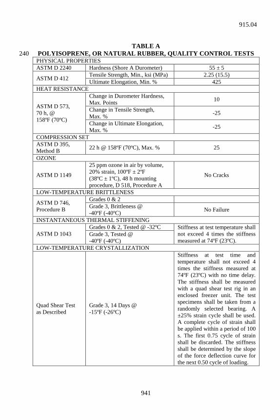
941
TABLE A
POLYISOPRENE, OR NATURAL RUBBER, QUALITY CONTROL TESTS 240 PHYSICAL PROPERTIES ASTM D 2240 Hardness (Shore A Durometer) 55 ± 5
ASTM D 412 Tensile Strength, Min., ksi (MPa) 2.25 (15.5) Ultimate Elongation, Min. % 425
HEAT RESISTANCE
ASTM D 573, 70 h, @ 158ºF (70ºC)
Change in Durometer Hardness, Max. Points 10
Change in Tensile Strength, Max. % -25
Change in Ultimate Elongation, Max. % -25
COMPRESSION SET ASTM D 395, Method B 22 h @ 158ºF (70ºC), Max. % 25
OZONE
ASTM D 1149
25 ppm ozone in air by volume, 20% strain, 100ºF ± 2ºF (38ºC ± 1ºC), 48 h mounting procedure, D 518, Procedure A
No Cracks
LOW-TEMPERATURE BRITTLENESS
ASTM D 746, Procedure B
Grades 0 & 2 Grade 3, Brittleness @ -40ºF (-40ºC) No Failure
INSTANTANEOUS THERMAL STIFFENING
ASTM D 1043 Grades 0 & 2, Tested @ -32ºC Stiffness at test temperature shall
not exceed 4 times the stiffness measured at 74ºF (23ºC).
Grade 3, Tested @ -40ºF (-40ºC)
LOW-TEMPERATURE CRYSTALLIZATION
Quad Shear Test as Described
Grade 3, 14 Days @ -15ºF (-26ºC)
Stiffness at test time and temperature shall not exceed 4 times the stiffness measured at 74ºF (23ºC) with no time delay. The stiffness shall be measured with a quad shear test rig in an enclosed freezer unit. The test specimens shall be taken from a randomly selected bearing. A ±25% strain cycle shall be used. A complete cycle of strain shall be applied within a period of 100 s. The first 0.75 cycle of strain shall be discarded. The stiffness shall be determined by the slope of the force deflection curve for the next 0.50 cycle of loading.
915.04
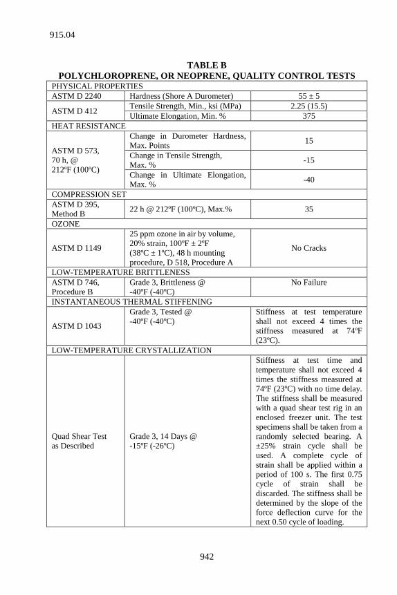
942
TABLE B
POLYCHLOROPRENE, OR NEOPRENE, QUALITY CONTROL TESTS PHYSICAL PROPERTIES ASTM D 2240 Hardness (Shore A Durometer) 55 ± 5
ASTM D 412 Tensile Strength, Min., ksi (MPa) 2.25 (15.5) Ultimate Elongation, Min. % 375
HEAT RESISTANCE
ASTM D 573, 70 h, @ 212ºF (100ºC)
Change in Durometer Hardness, Max. Points 15
Change in Tensile Strength, Max. % -15
Change in Ultimate Elongation, Max. % -40
COMPRESSION SET ASTM D 395, Method B 22 h @ 212ºF (100ºC), Max.% 35
OZONE
ASTM D 1149
25 ppm ozone in air by volume, 20% strain, 100ºF ± 2ºF (38ºC ± 1ºC), 48 h mounting procedure, D 518, Procedure A
No Cracks
LOW-TEMPERATURE BRITTLENESS ASTM D 746, Procedure B
Grade 3, Brittleness @ -40ºF (-40ºC)
No Failure
INSTANTANEOUS THERMAL STIFFENING
ASTM D 1043
Grade 3, Tested @ -40ºF (-40ºC)
Stiffness at test temperature shall not exceed 4 times the stiffness measured at 74ºF (23ºC).
LOW-TEMPERATURE CRYSTALLIZATION
Quad Shear Test as Described
Grade 3, 14 Days @ -15ºF (-26ºC)
Stiffness at test time and temperature shall not exceed 4 times the stiffness measured at 74ºF (23ºC) with no time delay. The stiffness shall be measured with a quad shear test rig in an enclosed freezer unit. The test specimens shall be taken from a randomly selected bearing. A ±25% strain cycle shall be used. A complete cycle of strain shall be applied within a period of 100 s. The first 0.75 cycle of strain shall be discarded. The stiffness shall be determined by the slope of the force deflection curve for the next 0.50 cycle of loading.
915.04
943
The bond strength, determined in accordance with ASTM D 429 Method B, shall be at least 40 lb/in. (7 N/mm). The adhesion failure, determined in accordance with ASTM D 429 Method B, shall be at least R-80. The adhesion-failure requirement will be waived if the bond 250 strength is at least 80 lb/in. (14 N/mm). 2. Structural Steel Structural steel spacer plates and other steel components, including anchor bolts, shall be galvanized in accordance with AASHTO M 111. 3. Internal Steel Shims Internal steel shims shall be rolled hot and cold steel and shall be in accordance with AISI 1015 through 1025, ASTM A 1008 (A 1008M), or ASTM A 1011 (A 1011M) grade 36 or higher. 260 4. Threaded Stud Threaded studs, where required, shall be in accordance with ASTM A 307 (A 307M) and mechanically zinc coated in accordance with AASHTO M 298, class 50. 5. Side Retainer Side retainers shall be made from plates or rolled mild steel in accordance with ASTM A 36 (ASTM A 36M). 270 (c) Manufacturing Requirements Plain bearings may be molded individually, cut from previously molded strips or slabs, or extruded and cut to length. Cut edges shall be at least as smooth as ANSI B 46.1 No. 250 finish. Unless otherwise shown on the plans, all components of a laminated bearing shall be molded together into an integral unit. Air bubbles within the elastomeric material shall be cause for rejection. Laminated elastomeric bearings shall be individually molded to the required size. Corners and edges may be rounded with a radius at the corners not exceeding 3/8 in. (10 mm) and a radius at the edges not exceeding 1/4 in. (6 mm). 280 Steel shims shall be sandblasted and cleaned and protected against contaminants until fabrication is completed. Bearings designed as a single unit shall be built as a single unit. Each reinforced bearing shall be marked with indelible ink or flexible paint. The marking shall consist of the orientation, the order number, lot number, bearing identification number, and elastomer type and grade number. Unless otherwise specified, the marking shall be on a face that is visible after erection of the bridge. 290
915.04
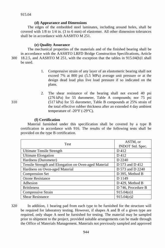
944
(d) Appearance and Dimensions The edges of the embedded steel laminates, including around holes, shall be covered with 1/8 to 1/4 in. (3 to 6 mm) of elastomer. All other dimension tolerances shall be in accordance with AASHTO M 251. (e) Quality Assurance The mechanical properties of the materials and of the finished bearing shall be in accordance with the AASHTO LRFD Bridge Construction Specifications, Article 18.2.5, and AASHTO M 251, with the exception that the tables in 915.04(b)1 shall 300 be used. 1. Compressive strain of any layer of an elastomeric bearing shall not
exceed 7% at 800 psi (5.5 MPa) average unit pressure or at the design dead load plus live load pressure if so indicated on the plans.
2. The shear resistance of the bearing shall not exceed 40 psi
(276 kPa) for 55 durometer, Table A compounds; nor 75 psi (517 kPa) for 55 durometer, Table B compounds at 25% strain of 310 the total effective rubber thickness after an extended 4 day ambient temperature of -20°F (-29°C).
(f) Certification Material furnished under this specification shall be covered by a type B certification in accordance with 916. The results of the following tests shall be provided on the type B certification.
Test ASTM, or INDOT Std. Spec.
Ultimate Tensile Strength D 412 Ultimate Elongation D 412 Hardness (Durometer) D 2240 Tensile Strength and Elongation on Oven-aged Material D 573 and D 412 Hardness on Oven-aged Material D 573 and D 2240 Compression Set D 395, Method B Ozone Resistance D 1149 Adhesion D 429, Method B Brittleness D 746, Procedure B Compressive Strain 915.04(e)1 Shear Resistance 915.04(e)2
In addition, 1 bearing pad from each type to be furnished for the structure will 320 be required for laboratory testing. However, if shapes A and B of a given type are required, only shape A need be furnished for testing. The material may be sampled prior to shipment to the project, provided suitable arrangements can be made through the Office of Materials Management. Materials not previously sampled and approved
915.04
945
for use shall be sampled after delivery to the project site. Samples shall be furnished at least 30 days before date of use. 915.05 Bearing Assemblies with Polytetrafluoroethylene, PTFE, Sliding Surfaces A copy of the manufacturer’s design manual shall be submitted for approval 330 when directed. All steel components shall be in accordance with ASTM A 709 Grade 36 (ASTM A 709M Grade 250) unless otherwise shown on the plans. Where these assemblies are to be used in conjunction with a self-weathering steel bridges, the steel components shall be in accordance with ASTM A 709 Grade 50W (ASTM A 709M Grade 345W). Stainless steel mating surfaces shall be 14 gage minimum ASTM A 240 type 304 sheets with a maximum surface roughness of 20 Rms. The PTFE shall be 100% virgin unfilled polymer or 15% glass filled and etched 340 on the bonding side. The properties of the PTFE shall be in accordance with the following: REQUIREMENT TEST METHOD VALUE Tensile Strength, minimum ASTM D 638 2,500 psi (17.24 MPa) Elongation, min. percent ASTM D 638 200 Specific Gravity ASTM D 792 2.1 to 2.3 PTFE, where required, shall be bonded to grit blasted steel. The PTFE guides 350 shall be bonded and mechanically fixed into place. The bonding compound used to bond PTFE or elastomeric pads to steel plates shall be in accordance with ASTM D 429, Method B. All steel surfaces exposed to the environment shall be zinc metallized and shall be 7 mils (175 µm) thick in accordance with CSA G-189, or painted with structural primer in accordance with 909.02(a). The finish coat for painted steel shall be in accordance with 909.02(d). The color shall be in accordance with Federal Color Standard 595, color No. 30045. 360 All required materials shall be covered by a type B certification in accordance with 916.
915.05
946
SECTION 916 – MATERIALS CERTIFICATIONS 916.01 General Materials certifications will be required for certain materials in accordance with various sections of these specifications and other contract documents. Unless otherwise specified or directed, 1 copy of each certification shall be submitted prior to use of the material. All certifications shall be signed by a person having legal authority to bind the company preparing the certification. The contract number, name of the Contractor, destination to which the material 10 covered by the certification is consigned, and name and quantity of material represented shall be shown on all copies of the certification. Identifying information such as alloy, grade, type, class, or other similar designation shall also be shown when applicable. Any material received on the project for which certification has been furnished may be sampled and tested. If the results of the tests are in disagreement with the certification, the test results shall prevail and further acceptance by certification from the manufacturer of the material concerned may be suspended. 20 916.02 Types of Certifications Certifications shall be type A, type B, type C, type D, or as required under other types. When specified, the type of certification provided for a material shall be in accordance with the Frequency Manual except as otherwise specified. Specific information and test results required in type A, type B, and other types of certifications will be listed in the material specifications. Sample forms for type A, type B, type C, and type D certifications are shown in 916.03. Sample forms for other type certifications are shown in 916.03 or ITM 804. (a) Type A 30 Type A certification shall be prepared by the manufacturer. It shall consist of a certified copy of a laboratory report which lists results of the specified tests and shall certify that the materials furnished comply with the specifications. The applicable specification shall be referred to in the certification. The tests may be conducted in the laboratory of the manufacturer or in another qualified laboratory. Such tests shall have been conducted on samples obtained from the lot or lots of material in the shipment. (b) Type B Type B certification shall be prepared by the manufacturer. It shall show the 40 limits of test values for the specified tests and shall certify that the materials furnished comply with the specifications. The applicable specification shall be referred to in the certification. The tests may be conducted in the laboratory of the manufacturer or in another qualified laboratory.
916.01
947
(c) Type C Type C certification shall be prepared by the manufacturer and shall certify that the materials furnished are in accordance with the specifications. The applicable specification shall be referred to in the certification. 50 (d) Type D Type D certification shall be prepared by the Contractor and shall certify that the materials furnished are in accordance with the specifications. The applicable specification shall be referred to in the certification. A type D certification shall be used for product identification. It may be required to certify that the material is in accordance with minimum trade standards. (e) Other Types Types of certifications other than type A, B, C, and D are specified for selected materials. The requirements for a certification are described in the material’s 60 specification. (f) Requirements for Small Quantities of Materials Where circumstances warrant and previously approved material is not available, small quantities may be accepted either by a type D certification or by an affidavit from the supplier stating that the material offered is equal to that specified. (g) Buy America Requirement All steel and cast iron materials and products used in the contract shall be certified to be in accordance with 106.01(c). 70 916.03 Sample Forms (a) For Buy America Requirement
BUY AMERICA CERTIFICATION In accordance with Indiana Department of Transportation Specification 106.01(c), I hereby certify that all steel and cast iron materials and products incorporated in Contract No. _______ were produced and manufactured in the 80 United States of America or territories subject to its jurisdiction. _________ _______________________________________ Date CONTRACTOR ________________________________________ SIGNATURE
916.03
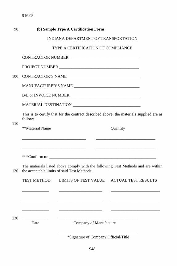
948
(b) Sample Type A Certification Form 90
INDIANA DEPARTMENT OF TRANSPORTATION
TYPE A CERTIFICATION OF COMPLIANCE CONTRACTOR NUMBER __________________________________ PROJECT NUMBER _______________________________________ CONTRACTOR’S NAME ___________________________________ 100 MANUFACTURER’S NAME ________________________________ B/L or INVOICE NUMBER __________________________________ MATERIAL DESTINATION _________________________________ This is to certify that for the contract described above, the materials supplied are as follows: 110 **Material Name Quantity _______________________________ _____________________________ _______________________________ _____________________________ ***Conform to: ____________________________________________________ The materials listed above comply with the following Test Methods and are within the acceptable limits of said Test Methods: 120 TEST METHOD LIMITS OF TEST VALUE ACTUAL TEST RESULTS _____________ _____________________ ________________________ _____________ _____________________ ________________________ _____________ _____________________ ________________________ _____________ ______________________________________ 130 Date Company of Manufacture ______________________________________ *Signature of Company Official/Title
916.03
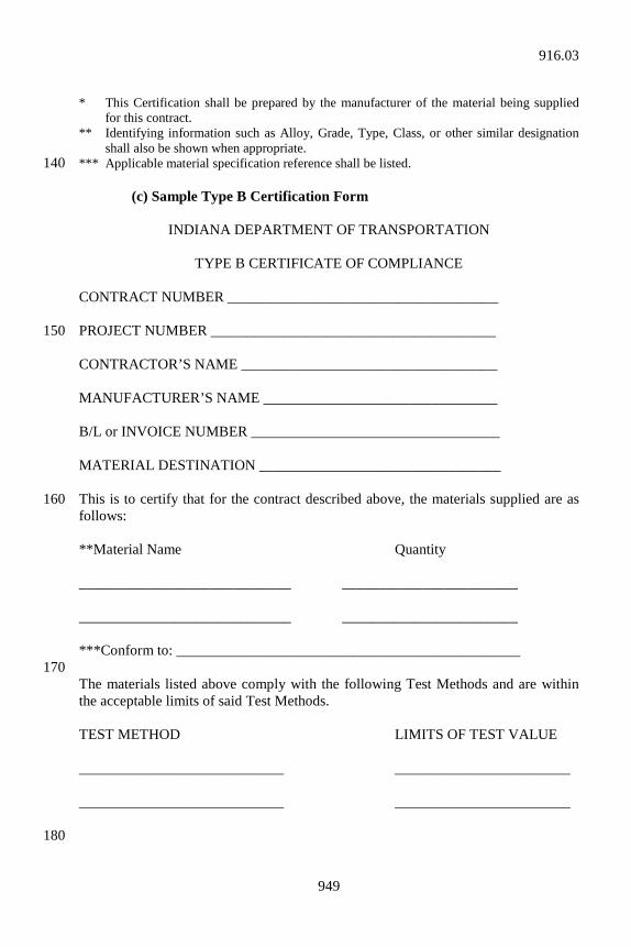
949
* This Certification shall be prepared by the manufacturer of the material being supplied
for this contract. ** Identifying information such as Alloy, Grade, Type, Class, or other similar designation
shall also be shown when appropriate. *** Applicable material specification reference shall be listed. 140 (c) Sample Type B Certification Form
INDIANA DEPARTMENT OF TRANSPORTATION
TYPE B CERTIFICATE OF COMPLIANCE CONTRACT NUMBER _____________________________________ PROJECT NUMBER _______________________________________ 150 CONTRACTOR’S NAME ___________________________________ MANUFACTURER’S NAME ________________________________ B/L or INVOICE NUMBER __________________________________ MATERIAL DESTINATION _________________________________ This is to certify that for the contract described above, the materials supplied are as 160 follows: **Material Name Quantity _____________________________ ________________________ _____________________________ ________________________ ***Conform to: _______________________________________________ 170 The materials listed above comply with the following Test Methods and are within the acceptable limits of said Test Methods. TEST METHOD LIMITS OF TEST VALUE ____________________________ ________________________ ____________________________ ________________________
180
916.03
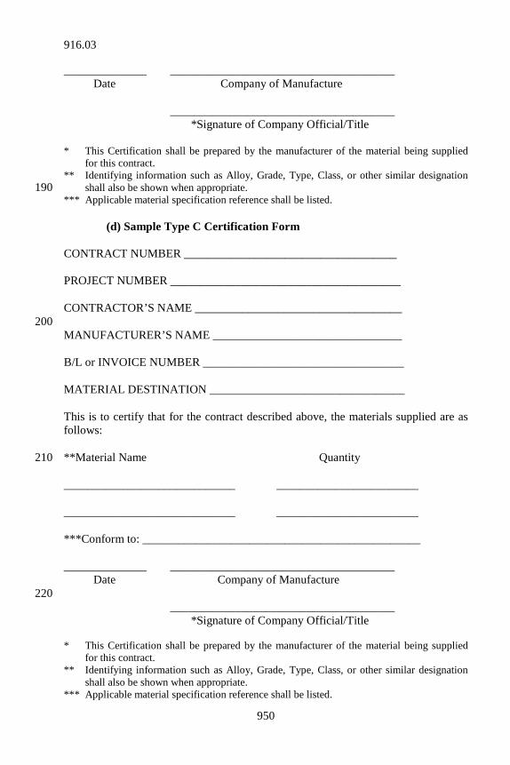
950
______________ ______________________________________ Date Company of Manufacture ______________________________________ *Signature of Company Official/Title * This Certification shall be prepared by the manufacturer of the material being supplied
for this contract. ** Identifying information such as Alloy, Grade, Type, Class, or other similar designation
shall also be shown when appropriate. 190 *** Applicable material specification reference shall be listed. (d) Sample Type C Certification Form CONTRACT NUMBER ____________________________________ PROJECT NUMBER _______________________________________ CONTRACTOR’S NAME ___________________________________ 200 MANUFACTURER’S NAME ________________________________ B/L or INVOICE NUMBER __________________________________ MATERIAL DESTINATION _________________________________ This is to certify that for the contract described above, the materials supplied are as follows: **Material Name Quantity 210 _____________________________ ________________________ _____________________________ ________________________ ***Conform to: _______________________________________________ ______________ ______________________________________ Date Company of Manufacture 220 ______________________________________ *Signature of Company Official/Title * This Certification shall be prepared by the manufacturer of the material being supplied
for this contract. ** Identifying information such as Alloy, Grade, Type, Class, or other similar designation
shall also be shown when appropriate. *** Applicable material specification reference shall be listed.
916.03
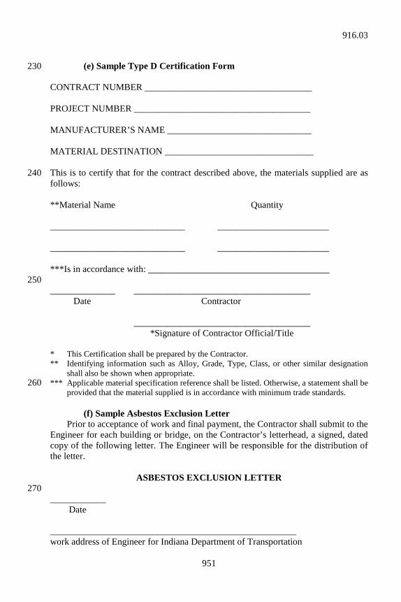
951
(e) Sample Type D Certification Form 230 CONTRACT NUMBER ____________________________________ PROJECT NUMBER ______________________________________ MANUFACTURER’S NAME _______________________________ MATERIAL DESTINATION ________________________________ This is to certify that for the contract described above, the materials supplied are as 240 follows: **Material Name Quantity _____________________________ ________________________ _____________________________ ________________________ ***Is in accordance with: _______________________________________ 250 ______________ ______________________________________ Date Contractor ______________________________________ *Signature of Contractor Official/Title * This Certification shall be prepared by the Contractor. ** Identifying information such as Alloy, Grade, Type, Class, or other similar designation
shall also be shown when appropriate. *** Applicable material specification reference shall be listed. Otherwise, a statement shall be 260
provided that the material supplied is in accordance with minimum trade standards. (f) Sample Asbestos Exclusion Letter Prior to acceptance of work and final payment, the Contractor shall submit to the Engineer for each building or bridge, on the Contractor’s letterhead, a signed, dated copy of the following letter. The Engineer will be responsible for the distribution of the letter.
ASBESTOS EXCLUSION LETTER 270 ____________ Date _____________________________________________________ work address of Engineer for Indiana Department of Transportation
916.03
952
ATT: ______________________________ Name, Project Engineer/Supervisor Re: Asbestos Exclusion 280 Location/Description ............................. ___________ Contract Number ................................... ___________ Bridge Structure Number ....................... ___________ Contractor’s Name ................................. ___________ Dear Engineer: I hereby certify that to the best of my knowledge no asbestos containing material was used as a building material in this project. 290 Very truly yours, ________________________________ Signature of Contractor official ________________________________ Title of Contractor official cc: District Bridge Inspection Engineer Environment, Planning and Engineering Division Chief 300 Project File SECTION 917 – QUALITY ASSURANCE AGGREGATE CERTIFICATION
917.01 General Requirements An aggregate source will be authorized to ship products in the status of a Certified Aggregate Producer who is in accordance with the required standards of ITM 211. This will consist of a program which will require the aggregate source to make a commitment to product quality management. Approval to participate in the program will be based on the following criteria. (a) existence of suitable materials in the deposit being mined; 10 (b) facilities capable of consistently processing uniform materials in
accordance with the specification requirements; and (c) a source Quality Control Plan which will ensure that the mineral
aggregates have a 95% assurance of being in accordance with the Department’s quality and uniformity requirements.
917.01
953
Specific details of this program are contained in ITM 211. Sampling and testing details are found in the Inspection and Sampling Procedures for Fine and Coarse 20 Aggregates manual. A Certified Aggregate Producer shall operate in accordance with the requirements of both publications. 917.02 Quality Control Plan An aggregate source will not be approved as a Certified Aggregate Producer until it has prepared a Quality Control Plan and the plan has been approved. The plan shall encompass all details of production starting with the extraction of the indigenous raw materials and concluding with material shipped from the plant. The Quality Control Plan shall be prepared in accordance with the requirements of ITM 211. 30 917.03 Source Approval Requirements The Office of Materials Management shall be notified in writing that the aggregate source wants to become a Certified Aggregate Producer. The aggregate source shall identify the specific products for which approval is sought. Such list shall include all of the products to be produced at the source regardless of whether the products are for Department or other uses. An aggregate source may not be considered for entry into the certification program until the preliminary source investigation has been completed in accordance 40 with Indiana Test Method 203. The following procedure will be used to establish an aggregate source as a Certified Aggregate Producer. (a) Step 1 The source shall enter the coordinated testing phase of ITM 211. Coordinated testing shall be performed in accordance with ITM 211. During this phase, the producer shall be required to develop a Quality Control Plan to establish demonstrated mean test values and standard deviations. 50 (b) Step 2 The aggregate source shall enter the trial phase. The producer shall also operate in accordance with ITM 211 and the Quality Control Plan. The Quality Control Plan shall be refined as may be necessary. (c) Step 3 The aggregate source will become an approved Certified Aggregate Producer following satisfactory performance during the trial phase. Achieving such status shall be accompanied by the inherent responsibility to operate within the tenets of 60 ITM 211. The Certified Aggregate Producer shall produce material at a compliance requirement of effectively 95% of the appropriate specifications. The Department will monitor such compliance through the use of periodic in-depth inspections of the production site. Continuing approval is contingent upon the effectiveness of the
917.03
954
producer’s Quality Control Plan as evidenced by the quality and uniformity of the products which are prepared in accordance with the appropriated specifications and ITM 211. 917.04 Removal from Certified Producer Status The Office of Materials Management will be responsible for the review and 70 removal of an aggregate source from being an approved Certified Aggregate Producer. A Certified Aggregate Producer shall operate so as to avoid a need for the Department to exercise this action. However, removal from Certified Aggregate Producer status may be necessary for situations such as: (a) the statistical probability of the product compliance has fallen below
90%; (b) the product has a 90% to 95% probability of compliance but the
producer has failed to take corrective action to restore 95% probability; 80 (c) the Certified Aggregate Producer has failed to take immediate
corrective action relative to deficiencies in the performance of the approved Quality Control Plan;
(d) evaluation of data has demonstrated an inability of the Certified
Aggregate Producer to consistently be in accordance with Department requirements;
(e) the Certified Aggregate Producer has deliberately shipped aggregate 90
material which is not in accordance with the specifications, or has falsified records; or
(f) the production site has not been operated in accordance with the
Summary of Production or Ledge Quality Results letter. Notice of removal from Certified status will be in written form, will be issued by the Office of Materials Management, and will identify the reasons for the removal. Effective immediately upon receipt of such notification, no further aggregate shipments shall be made on a certified basis. 100 917.05 Appeals The producer shall have the right to appeal removal from Certified Producer status to the Engineer. The appeal shall be in written form, shall state the reason or reasons on which the appeal is based, and shall be received within 14 calendar days of receipt of the removal notice.
917.04
955
SECTION 918 – SOIL FABRICS 918.01 Fabric for Waterproofing Fabric for waterproofing shall be treated cotton in accordance with AASHTO M 117, woven glass in accordance with ASTM D 1668, or glass fiber mat in accordance with ASTM D 2178. Material furnished under this specification shall be covered by a type C certification in accordance with 916. 918.02 Geotextile for Use Under Riprap The material used shall consist of a non-woven geotextile consisting of strong, 10 rot resistant, chemically stable long-chain synthetic polymer material dimensionally stable with distinct and measurable openings. The plastic yarn or fibers used in the geotextile, shall consist of any long-chain synthetic polymer composed of at least 85% by weight of polyolefins, polyesters, or polyamides, and shall contain stabilizers and inhibitors added to the base plastic to make the filaments resistant to deterioration due to ultraviolet and heat exposure. The geotextile shall be calendared or otherwise finished so that the yarns or fibers will retain their relative position with respect to each other. Silt film geotextiles will not be permitted unless approved. The geotextile shall meet the following physical requirements. 20
GEOTEXTILE MATERIAL PROPERTIES TEST METHOD REQUIREMENTS*
Tensile Strength Grab Tensile Strength, ASTM D 4632
200 lb (890 N)
Elongation Grab Tensile Strength, ASTM D 4632
15%
Seam Strength Grab Tensile Strength, ASTM D 4632
180 lb (800 N)
Puncture Strength ASTM D 4833 80 lb (356 N) Trapezoid Tear ASTM C 4533 50 lb (225 N) Ultraviolet Degradation at 150 h
ASTM D 4355 70% strength retained
Apparent Opening Size (AOS)
ASTM D 4751 AOS shall be No. 50 (300 µm)
standard sieve or filter Permeability** ASTM D 4491 (Permittivity) 0.01 cm/sec or > * Use value in weaker principal direction. All numerical values represent minimum
average roll value and test results from any sampled roll in a lot shall meet or exceed the minimum values in the table. Lots shall be sampled according to ASTM D 4354.
** The nominal coefficient of permeability shall be determined by multiplying permittivity value by nominal thickness. The nominal thickness is measured under a normal load of 280 psi (1.93 MPa).
The geotextiles to be used will be selected from the list of approved Geotextiles for Use Under Riprap.
918.02
956
A manufacturer requesting that a geotextile be added to the approved list shall provide a certification documenting compliance with the above requirements and a sample to the Office of Materials Management. The certification shall be prepared by the manufacturer which addresses all the required information as shown on a sample 30 certification form in ITM 804. No relabeled materials will be considered for approval. A specified material on the approved list will not be listed under more than 1 name. When it is determined the material is acceptable, it will be added to the list of approved Geotextiles for Use Under Riprap and it may be used upon publication of the list. 918.03 Geotextile for Use With Underdrains This material shall consist of a non-woven needle punched or heat bonded 40 geotextile consisting of strong, rot resistant, chemically stable long-chain synthetic polymer materials, which are dimensionally stable relative to each other including selvedges. The plastic yarn or fibers used in the geotextile shall consist of at least 85% by weight of polyolefins, polyesters, or polyamides. The plastic yarn or fibers shall have stabilizers and inhibitors added to the base plastic to make the filaments resistant to deterioration due to ultraviolet and heat exposure. The geotextile shall be in accordance with the physical requirements as follows:
TEST METHOD REQUIREMENTS2 Grab Strength ASTM D 4632 80 lb (355.8 N) Seam Strength1 ASTM D 4632 70 lb (311.4 N) Puncture Strength ASTM D 4833 25 lb (111.2 N) Trapezoid Tear ASTM D 4533 25 lb (111.2 kg) Apparent Opening Size (AOS) ASTM D 4751 Sieve No. 50 or smaller
opening Permeability ASTM D 4491 0.1 mm/sec Ultraviolet Degradation at 150 h ASTM D 4355 70% strength retained 1 Values will apply to both filed and manufactured seams. 2 The value in the weaker principal direction shall be used. All numerical values will
represent the minimum average roll value. Test results from a sampled roll in a lot shall be in accordance with or shall exceed the minimum values shown in the table. Lots shall be sampled in accordance with ASTM D 4354.
50 The geotextiles to be used shall be selected from the list of approved Geotextiles for Use With Underdrains. A manufacturer requesting that a geotextile be added to the approved list shall provide a certification documenting compliance with the above requirements and a sample to the Office of Materials Management. The certification shall be prepared by the manufacturer in accordance with 916. No relabeled materials will be considered for approval. A specified material on the approved list will not be listed under more than 1 name. When it is determined the material is acceptable, it will be added to the
918.03
957
list of approved Geotextiles for Use with Underdrains and it may be used upon 60 publication of the list. 918.04 Geotextile for Silt Fence The silt fence fabric shall consist of a woven or non-woven geotextile consisting of strong, rot resistant, chemically stable long-chain synthetic polymer materials, which are dimensionally stable relative to each other including selvedges. The plastic yarn or fibers used in the geotextile shall consist of at least 85% by weight of polyolefins, polyesters, or polyamides. The plastic yarn or fibers shall have stabilizers and inhibitors added to the base plastic to make the filaments resistant to deterioration due to ultraviolet and heat exposure. 70 The geotextile shall be in accordance with the guidelines of AASHTO-AGC-ARTBA, Task Force 25 and AASHTO M 288. The geotextile shall be in accordance with the physical requirements as follows.
TEST METHOD REQUIREMENTS1 Wire Fence
Supported Self Supported
Grab Strength ASTM D 4632 90 lb (41 kg) 90 lb (41 kg) Elongation at 45 lb (20 kg) ASTM D 4632 50% Max. Apparent Opening Size2 ASTM D 4751 No. 20
(0.84 mm) No. 20 (0.84 mm)
Permittivity2 ASTM D 4491 0.01 sec-1 0.01 sec-1 Ultraviolet Degradation at 500 h
ASTM D 4355 70% strength retained
70% strength retained
1. The value in the weaker principal direction shall be used. All numerical values will represent the minimum average roll value. Test results from a sampled roll in a lot shall be in accordance with or shall exceed the minimum values shown in the above table. The stated values are for non-critical, non-severe conditions. Lots shall be sampled in accordance with ASTM D 4354.
2. The values reflect the minimum criteria currently used. Performance tests may be used to evaluate silt fence performance if deemed necessary by the Engineer.
Material furnished under this specification shall be covered by the type of certification specified in the Frequency Manual and in accordance with 916. 80 918.05 Geogrid Geogrid shall be on a regular network of integrally connected polymer tensile elements with aperture geometry sufficient to permit significant mechanical interlock with the surrounding material. The geogrid structure shall be dimensionally stable and shall be able to retain its geometry under construction stresses. The geogrid structure shall have a resistance to damage during construction, ultraviolet degradation, and all forms of chemical and biological degradation encountered in the soil being placed on.
918.05
958
Geogrid shall be in accordance with the property requirements as specified in 90 the Geosynthetic Research Institute Standard Test Methods GG1, GG3, GG4, and ASTM D 5262. During periods of shipment and storage, the geogrid shall be protected from temperatures greater than 140°F (60°C), mud, dirt, dust, and debris. Each geogrid roll shall be labeled or tagged to provide product identification. The manufacturer’s recommendations shall be followed with regard to protection from direct sunlight. At the time of installation, the geogrid will be rejected if it has defects, tears, punctures, flaws, deterioration, or damage incurred during manufacture, transportation, or storage. All damaged portions of geogrid for the entire width shall be replaced. 100 Only geogrids selected from the Department’s list of approved Geogrids shall be used. Geogrids will be placed and maintained on the Department’s list in accordance with ITM 806, procedure C. No relabeled materials will be considered for approval. A specified material shown on the approved list will not be listed under more than 1 name. The geogrid shall be in accordance with the property requirements for the type specified as follows. 110 (a) Type I
PROPERTY TEST METHOD UNIT VALUE, Min. Aperture Calibered in. (mm) 0.5 by 0.5 (13 by 13) Open Area COE, CWO2215 percent > 50.0, ≤ 80.0 Tensile Modulus, machine direction cross machine direction
ASTM D 66371,2,3
lb/ft (N/m) lb/ft (N/m)
10,000 (146,000) 10,000 (146,000)
Ultimate Strength, machine direction cross machine direction
ASTM D 66372,3
lb/ft (N/m) lb/ft (N/m)
800 (11,670) 800 (11,670)
1. Secant modulus at 5% elongation. 2. Results for machine direction, MD, and cross machine direction, CMD, are required. 3. Minimum average roll values shall be in accordance with ASTM D 4759. (b) Type II
PROPERTY TEST METHOD UNIT VALUE, Min. Open Area COE, CWO2215 percent > 50.0, ≤ 80.0 Tensile Modulus, machine direction
ASTM D 66371,2
lb/ft (N/m)
49,300 (720,000)
Creep Limited Strength, machine direction at 5% strain
ASTM D 5262
lb/ft (N/m)
1,090 (16,000)
1. Secant modulus at 2% elongation. 2. Minimum average roll values shall be in accordance with ASTM D 4759.
918.05
959
SECTION 919 – TRAFFIC SIGNS
919.01 Traffic Signs Traffic signs shall be in accordance with the MUTCD. Panel sign fabrication shall not utilize overlapping or butt splicing of reflective sheeting. Roll splices, as supplied on the roll of sheeting by the sheeting manufacturer, are permitted subject to the following conditions. (a) a maximum of 1 roll splice per panel, and 10 (b) a maximum of 3 roll splices per sign. Exit panels are considered a part of the signs to which they are attached when fabricated under the same contract. If the exit panels are made for separate installation, only 1 roll splice is permitted on the entire sign. Overlap splices on sheet signs will be permitted only because of insufficient sheeting width on signs whose smaller dimension exceeds 48 in. (1,220 mm). The overlap splice shall be installed in a shingle type manner using a horizontal lap. The 20 lap width shall be a minimum of 1/4 in. (6 mm). Butt splices shall not be used. Roll splices are permitted on sheet signs but shall not exceed 1 splice per sign. All signs shall be packed for shipment and handled during construction in accordance with the manufacturer’s recommendations. All sign or sign face damaged prior to acceptance shall be replaced or repaired. Damaged sheet signs shall be replaced in their entirety. Damaged panel signs shall have the affected panels replaced or repaired in accordance with the manufacturer’s recommendations. Repaired areas on panel signs shall not be larger than 3 in. by 3 in. (75 mm by 30 75 mm). Repaired areas 1 in. by 1 in. (25 mm by 25 mm) or less shall be limited to a maximum of 3 per panel and a maximum of 6 per panel sign. Repaired areas larger than 1 in. by 1 in. (25 mm by 25 mm) shall be limited to 1 per panel and a maximum of 3 per panel sign. The maximum number of repaired areas shall be 3 on a panel or 6 on a panel sign. No more than 20% of the total number of panel signs may be patched. Panels with sheeting cracked at the bend around the panel edge shall be replaced. A sign with the metal face damaged greater than superficial deformation shall be replaced. 40 (a) Backing Material Fabrication, including cutting and punching of holes but excluding holes for demountable copy, shall be completed prior to surface treatment. Material shall be
919.01
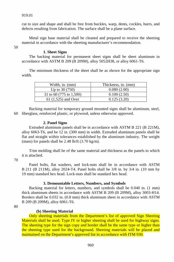
960
cut to size and shape and shall be free from buckles, warp, dents, cockles, burrs, and defects resulting from fabrication. The surface shall be a plane surface. Metal sign base material shall be cleaned and prepared to receive the sheeting material in accordance with the sheeting manufacturer’s recommendation. 50 1. Sheet Signs The backing material for permanent sheet signs shall be sheet aluminum in accordance with ASTM B 209 (B 209M), alloy 5052H38, or alloy 6061-T6. The minimum thickness of the sheet shall be as shown for the appropriate sign width.
Width, in. (mm) Thickness, in. (mm) Up to 30 (750) 0.080 (2.00)
31 to 60 (775 to 1,500) 0.100 (2.50) 61 (1,525) and Over 0.125 (3.20)
Backing material for temporary ground mounted signs shall be aluminum, steel, fiberglass, reinforced plastic, or plywood, unless otherwise approved. 60 2. Panel Signs Extruded aluminum panels shall be in accordance with ASTM B 221 (B 221M), alloy 6063-T6, and be 12 in. (300 mm) in width. Extruded aluminum panels shall be flat and straight within tolerances established by the aluminum industry. The weight (mass) for panels shall be 2.48 lb/ft (3.70 kg/m). Trim molding shall be of the same material and thickness as the panels to which it is attached. 70 Panel bolts, flat washers, and lock-nuts shall be in accordance with ASTM B 211 (B 211M), alloy 2024-T4. Panel bolts shall be 3/8 in. by 3/4 in. (10 mm by 19 mm) standard hex head. Lock-nuts shall be standard hex head. 3. Demountable Letters, Numbers, and Symbols Backing material for letters, numbers, and symbols shall be 0.040 in. (1 mm) thick aluminum sheets in accordance with ASTM B 209 (B 209M), alloy 3003-H14. Borders shall be 0.032 in. (0.8 mm) thick aluminum sheet in accordance with ASTM B 209 (B 209M), alloy 6061-T6. 80 (b) Sheeting Material Only sheeting materials from the Department’s list of approved Sign Sheeting Materials shall be used. Type IV or higher sheeting shall be used for highway signs. The sheeting type for the sign copy and border shall be the same type or higher than the sheeting type used for the background. Sheeting materials will be placed and maintained on the Department’s approved list in accordance with ITM 930.
919.01
961
1. Reflective Sheeting Reflective sheeting used for signs, channelizing and delineation devices shall be in accordance with AASHTO M 268. Type V reflective sheeting may be used on 90 delineators. Reboundable reflective sheeting shall be used on plastic drums, flexible delineator posts, and other flexible channelizers. The reflective sheeting shall include an adhesive backing Class 1 or Class 2 in accordance with AASHTO M 268. 2. Non-reflective Sheeting Non-reflective sheeting shall be in accordance with AASHTO M 268 except that the sheeting shall not incorporate optical elements. The color shall be black in accordance with Federal Standard 595, Color No. 17038. 100 3. Transparent Sheeting Transparent sheeting shall be a material recommended by the background sheeting manufacturer. (c) Letters, Numbers, Symbols, and Accessories Letters, numbers, symbols, and accessories shall be demountable. The reflective sheeting shall be of the same type as used on the background and mechanically applied to the properly prepared aluminum in a manner prescribed by 110 the sheeting manufacturer. Each demountable legend unit, supplemental panel, and border frame shall be supplied with mounting holes and shall be secured to the sign face with aluminum rivets with aluminum mandrels. Adhesives that, when removed, may damage the sign face, legend unit, or border shall not be used to hold the unit in place. Completed demountable units shall be dipped coated with a high gloss clear finish coat as specified by the sheeting manufacturer. The finished units shall be clean cut, sharp, and have essentially a plane surface. 120 (d) Fasteners 1. Sheet Signs The bolts, steel flat washers, and lock-nuts used to attach sheet signs to posts shall be stainless steel in accordance with ASTM A 276, or type 304 carbon steel in accordance with ASTM A 307, grade A. Carbon steel hardware shall be galvanized in accordance with ASTM A 153. Lock washers and hex nuts shall be used in lieu of the lock-nuts when carbon steel hardware is furnished. 130 The bolts shall be 5/16 in. by 3 in. (8 mm by 75 mm) hex head, full threaded. The steel flat washers shall be size no. 1/4, 0.738 in. (19 mm) outside diameter,
919.01
962
0.317 in. (8.1 mm) inside diameter, and 0.051 to 0.08 in. (1.2 to 2.0 mm) thick and in accordance with Military Specifications MS 15795-811. Nylon flat washers shall be 7/8 in. (22 mm) outside diameter, 0.317 in. (8.1 mm) inside diameter, and shall be 0.032 in. (0.81 mm) thick. 2. Panel Signs and Temporary Panel Signs The aluminum post clips shall be in accordance with ASTM B 26 (B 26M) or ASTM B 108 (B 108M), alloy 356.0-T6 and as shown on the plans. Aluminum post 140 clip bolts shall be as shown on the plans and in accordance with ASTM B 211 (B 211M), alloy 2024-T4. Lock-nuts shall be in accordance with ASTM B 211 (B 211M), alloy 2017-T4. Flat washers shall be in accordance with ASTM B 209 (B 209M), alloy Alclad 2024-T4. 3. Aluminum Rivets Aluminum rivets shall be determined by character size and shape but shall not be more than 8 in. (200 mm) on center. All rivets shall be color matched to the legend or supplemental panel being installed. 150 (e) Basis for Use Materials furnished under this specification, except those used for temporary construction signs, temporary traffic signs, and temporary panel signs, shall be covered by a type C certification in accordance with 916.
SECTION 920 – HIGHWAY ILLUMINATION MATERIALS 920.01 Highway Illumination Materials All luminaires, lamps, fuse kits, wire and cable, and major equipment shall be approved new material bearing the UL seal of approval or meet their standards. Descriptive and technical literature shall be furnished for approval on all equipment prior to purchase and incorporation into the work. Warranties for all major equipment shall be in accordance with 807.02. 10 (a) Lighting Standards and Mast Arms, under 80 ft (24.4 m) 1. General Requirements Conventional lighting standards shall be aluminum or steel and shall be in accordance with AASHTO Standard Specifications for Structural Supports for Highway Signs, Luminaires, and Traffic Signals. For conventional light standards, design wind velocity shall be 80 mph (129 km/h). The maximum horizontal deflection of the pole under maximum loading 20 conditions shall not exceed a deflection angle of 1° 10" from the vertical axis of the pole for any 1 ft (0.3 m) section of the pole along the entire length of the pole. The maximum stress shall be 80% of the AASHTO Standard Specifications for Group I-
920.01
963
DL loads. Vibration dampers shall be furnished as recommended by the manufacturer. The manufacturer may use drag coefficients based on actual wind tunnel tests; otherwise, they shall use the drag coefficients in Table 1.2.5c of Group I loads. Conventional light standards shall be designed to support a 53 lb (24 kg) luminaire with an effective area of 2.4 sq ft (0.22 m2). When larger luminaires are 30 specified, the light standards shall be designed to support the larger luminaires and this shall be shown on the light standard working drawings. Conventional poles shall have a 4 in. by 8 in. (100 mm by 200 mm) reinforced handhole centered 18 in. (460 mm) above the base of the pole and a cover attached with a minimum of 2 stainless steel hex head bolts. The pole shall have a removable pole cap and a wire support hook to support the vertical drop of the wire by a service drop clamp attached to the cable. A wiring hole with a 1 in. (25 mm) inside diameter grommet shall be provided where the arm is attached. Pole bases shall be designed for mounting on anchor bolts equally spaced on an 11 1/2 in. (292 mm) or 14 1/2 in. 40 (368 mm) diameter anchor bolt circle. Anchor bolt covers shall be furnished. Hardware shall be type 304 or 305 stainless steel in accordance with ASTM A 276, except where otherwise specified. For conventional poles, a 1/2 in. (13 mm) by 13 UNC threaded grounding nut or other approved method shall be provided near the bottom of and shall be accessible through the handhole for attaching the ground wire. The ground wire shall be No. 6 AWG soft-drawn, solid copper in accordance with ASTM B 3. 50 Mast arms less than 8 ft (2.4 m) in length shall either be single member or truss type, except that mast arms on bridge deck light standards shall be truss type. Single member arms shall be a tapered tube oval shaped at the pole end with the long dimension in the vertical plane, welded to a pole plate and bolted or clamped to the shaft with a minimum of four 1/2 in. (13 mm) bolts. Mast arms 8 ft (2.4 m) and over in length shall be truss type. The upper member shall be a tapered tube oval shaped at the pole with the long dimension in the horizontal plane. The lower member may be standard pipe. Both members shall be welded to a pole plate and bolted or clamped to the pole. A minimum of four 1/2 in. (13 mm) bolts at the upper member and a minimum of two 3/8 in. (10 mm) bolts at the lower member shall be used if a 60 pole plate configuration is used to attach the mast arm to the pole. Mast arms that are clamped to the pole shall have a minimum of four 1/2 in. (13 mm) bolts per clamp. Mast arms shall provide an enclosed raceway for the wiring and shall be free of burrs and rough edges. Each arm shall be furnished with a 2 in. (50 mm) nominal pipe size slipfitter. The maximum rise of the truss style arm shall be as set out in the table and shall be measured vertically from the centerline of the free end of the truss to a plane through the centerline of the upper arm bracket after loading.
920.01
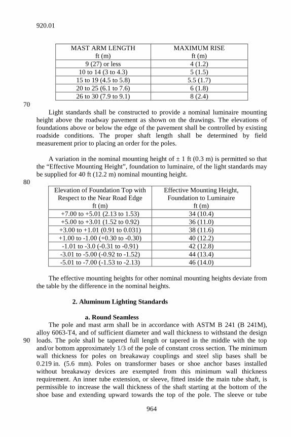
964
MAST ARM LENGTH
ft (m) MAXIMUM RISE
ft (m) 9 (27) or less 4 (1.2)
10 to 14 (3 to 4.3) 5 (1.5) 15 to 19 (4.5 to 5.8) 5.5 (1.7) 20 to 25 (6.1 to 7.6) 6 (1.8) 26 to 30 (7.9 to 9.1) 8 (2.4)
70 Light standards shall be constructed to provide a nominal luminaire mounting height above the roadway pavement as shown on the drawings. The elevations of foundations above or below the edge of the pavement shall be controlled by existing roadside conditions. The proper shaft length shall be determined by field measurement prior to placing an order for the poles. A variation in the nominal mounting height of ± 1 ft (0.3 m) is permitted so that the “Effective Mounting Height”, foundation to luminaire, of the light standards may be supplied for 40 ft (12.2 m) nominal mounting height. 80
Elevation of Foundation Top with Respect to the Near Road Edge
ft (m)
Effective Mounting Height, Foundation to Luminaire
ft (m) +7.00 to +5.01 (2.13 to 1.53) 34 (10.4) +5.00 to +3.01 (1.52 to 0.92) 36 (11.0)
+3.00 to +1.01 (0.91 to 0.031) 38 (11.6) +1.00 to -1.00 (+0.30 to -0.30) 40 (12.2) -1.01 to -3.0 (-0.31 to -0.91) 42 (12.8)
-3.01 to -5.00 (-0.92 to -1.52) 44 (13.4) -5.01 to -7.00 (-1.53 to -2.13) 46 (14.0)
The effective mounting heights for other nominal mounting heights deviate from the table by the difference in the nominal heights. 2. Aluminum Lighting Standards a. Round Seamless The pole and mast arm shall be in accordance with ASTM B 241 (B 241M), alloy 6063-T4, and of sufficient diameter and wall thickness to withstand the design loads. The pole shall be tapered full length or tapered in the middle with the top 90 and/or bottom approximately 1/3 of the pole of constant cross section. The minimum wall thickness for poles on breakaway couplings and steel slip bases shall be 0.219 in. (5.6 mm). Poles on transformer bases or shoe anchor bases installed without breakaway devices are exempted from this minimum wall thickness requirement. An inner tube extension, or sleeve, fitted inside the main tube shaft, is permissible to increase the wall thickness of the shaft starting at the bottom of the shoe base and extending upward towards the top of the pole. The sleeve or tube
920.01
965
extension shall be no less than 3 ft (0.9 m) in length, fabricated from aluminum alloy 6063-T4 and heat treated to produce a T6 temper after placing in the shaft. The minimum wall thickness of the combination of shaft and sleeve shall be 0.219 in. 100 (5.6 mm). Attaching plates or clamps for aluminum mast arms shall be in accordance with ASTM B 241 (B 241M), alloys 6061-T6, 6063-T6, 356.0-T6, or 5052-H32. The bottom end of the shaft shall be welded to a 1 piece cast aluminum shoe anchor base of 356.0-T6 aluminum alloy in accordance with ASTM B 26 (B 26M) for sand castings or ASTM B 108 for permanent mold castings or equal and provided with 4 slotted holes for anchor bolts and the shaft’s full length shall be heat treated to produce a T6 temper. The top of the shaft shall be provided with a removable aluminum pole cap. The shaft shall have no longitudinal welds. After fabrication, the shaft shall be cleaned to a satin finish and wrapped for protection during shipping and handling. 110 b. Single Longitudinal Welded The material for these lighting standards shall be round, tapered structural marine aluminum sheet in accordance with ASTM B 209 (B 209M), alloy 5086-H34, and of sufficient diameter and wall thickness to withstand the design loads. The minimum wall thickness for poles on breakaway couplings and steel slip bases shall be 0.219 in. (5.6 mm). Poles on transformer bases or shoe anchor bases installed with no breakaway devices are exempted from the minimum wall thickness requirement. The anchor base shall be 1 piece cast aluminum in accordance with ASTM B 26 (B 26M), alloy 356.0-T6. The base casting for the formed and welded shaft shall be 120 designed to be inserted a minimum of 12 in. (300 mm) into the shaft and bonded to the shaft with a weatherproof structural epoxy adhesive that fully develops the required strength as specified by the design criteria. After fabrication, the shaft shall be cleaned to a satin finish and wrapped for protection during shipping and handling. 3. Stainless Steel Lighting Standards Stainless steel lighting standards shall be fabricated from stainless steel in accordance with ASTM A 666, type 201, that has a minimum yield point of 68,000 psi (469 MPa). Welds other than spot welds shall be performed with conventional welding equipment and with stainless steel welding rods. Welds shall 130 be free of cracks and pores. The wall thickness and diameter of the pole shall be sufficient to withstand designed loads. Exposed surfaces of the standard shall be smooth and free from marks or imperfections. During shipment, the poles and mast arms shall be protected with a non-staining protective material to preserve the finish. 4. Galvanized Steel Lighting Standards The pole and base plate shall be fabricated from steel in accordance with ASTM A 572 (A 572M) A 595, or A 1011 with a minimum yield strength of 50,000 psi (345 MPa). Single member mast arms and the upper members of truss type mast arms shall be fabricated from steel in accordance with ASTM A 572 (A 572M) or 140 A 595 with a minimum yield strength of 50,000 psi (345 MPa). The lower member of truss type arms may be fabricated from standard steel pipe in accordance with ASTM A 53 with a minimum yield strength of 36,000 psi (250 MPa). After
920.01
966
fabrication, the pole and mast arm shall be thoroughly cleaned and galvanized in accordance with ASTM A 123. Steel standards shall be tapered 0.14 in./ft (11.67 mm/m) and shall be round, octagonal, or dodecagonal. The design load shall be used to determine the pole diameter and wall thickness. The pole shall have 1 longitudinal electrically welded joint. A steel base plate shall be welded to each pole and provided with 4 slotted 150 holes for the anchor bolts. All welds on steel standards shall be performed at the factory. Base plate welds shall be 100% penetration. Circumferential welds shall be backed-up welds with 100% penetration. Longitudinal welds shall be a minimum of 60% penetration. The 100% penetration welds shall be ultrasonically inspected and all other welds shall be inspected by magnetic particle. Welding shall be performed in accordance with 711.32. 5. Wood Pole Lighting Standards 160 Wood poles for highway lighting standards shall be in accordance with 922.05(b). 6. Frangible Breakaway Bases All light standards, except high mast towers and those protected by bridge end bents or retaining walls, shall be installed on breakaway devices. All breakaway devices on a contract shall be of the same type and manufacturer. Breakaway devices shall be in accordance with AASHTO Standard Specifications for Structural Supports for Highway Signs, Luminaires, and Traffic 170 Signals as modified in 920.01(a)1. A certification from the manufacturer shall be furnished with the shop drawings stating the breakaway devices conform to the breakaway criteria of the AASHTO Standard Specifications for Structural Supports for Highway Signs, Luminaires, and Traffic Signals. a. Cast Aluminum Transformer Base The anchor bolts for transformer bases shall be in accordance with 920.01(a)7. The anchor bolt circle for transformer bases shall be 15 in. (381 mm). The bolt holes 180 in the transformer base may be slotted. The pole shall be bolted to the transformer base with four 1 in. (25 mm) diameter galvanized steel bolts. An approved handhole in the transformer base may be substituted for the 4 in. by 8 in. (100 mm by 200 mm) handhole specified in 920.01(a)1. b. Breakaway Coupling Breakaway couplings may be used with aluminum poles with mounting heights up to 50 ft (15 m) and with steel poles that weigh 600 lb (272 kg) or less. The
920.01
967
couplings shall be furnished with necessary hardware including a 2 piece cover. 190 Couplings shall be installed in accordance with the manufacturer’s instructions and recommended clearance between the top of the foundation and the bottom of the breakaway coupling. 7. Anchor Bolts Anchor bolts shall be 1 in. (25 mm) with 8NC rolled threads in accordance with ASTM A 307. The minimum length of threads shall be 6 in. (150 mm). Mean diameter of rod stock shall be 0.918 in. ± 0.011 in. (23.32 mm ± 0.28 mm) and out-of-round tolerance shall be ± 0.012 in. (0.3 mm). The top 10 in. (254 mm) of the bolt shall be galvanized in accordance with ASTM A 153. Anchor bolts shall be in 200 accordance with 910.19(b). The bolts shall be a minimum of 36 in. (914 mm) in length for poles 8 in. (200 mm) outside diameter or less and 48 in. (1,219 mm) in length for poles 9 in. (230 mm) or 10 in. (254 mm) outside diameter. In addition to the minimum length, the bolt shall have a 4 in. (100 mm) right angle bend at the unthreaded end. The anchor bolts in bridge structures shall be as shown on the plans. (b) High Mast Standards of 80 ft (24.5 m) and Over The high mast pole, base, anchor bolts, lowering device, installed fixtures, and associated appurtenances shall be designed to withstand a minimum wind speed of 90 mph (145 km/h), gust of 117 mph (188 km/h), using applicable design criteria in 210 accordance with AASHTO Standard Specifications for Structural Supports for Highway Signs, Luminaires, and Traffic Signals. Minimum design criteria for each fixture shall be an effective projected area of 2.8 sq ft (0.26 m2) and a weight of 85 lb (38.6 kg). If larger fixtures are used, the actual size and weight shall be used in the design of the pole. The Contractor shall be responsible for the accuracy of the dimensions and the proper fit of all material and equipment furnished with the pole. The Contractor shall provide all applicable manufacturer’s warranties for material and workmanship. External lowering devices shall be designed to attach to the pole as shown on the 220 plans. The pole shall include the mounting accommodations as shown on the plans. 1. High Mast Poles The poles shall be tapered shafts having poly-sided or circular cross sections. The pole shaft sections shall be slip fitted and shall provide at least 1 in. (25 mm) radial clearance from all interior devices. All tower shaft components shall be fabricated from high strength, low alloy, steel in accordance with AASHTO M 270; ASTM A 595, Grade A or B; ASTM A 572, Grade 55; ASTM A 1011 (A 1011M); ASTM A 606, or ASTM A 808 (A 230 808M), with a minimum yield strength of 50,000 psi (345 MPa). Sections which are slip fitted shall have slip joints with a minimum overlap of 1.5 times the diameter of the bottom of the upper section at the slip joint. Towers having slip joint construction shall be match marked at the factory and shall be
920.01
968
shipped disassembled for assembly at the work site. Slip joints shall be marked to ensure that the 1.5 times diameter insertion is provided. All steel used in the base plate and shaft shall meet an impact property of 15 ft·lbs (20.3 J) at 40°F (4°C) in the longitudinal direction using the Charpy 240 V-Notch test. This shall be an average of 3 tests per mill heat with no test below 10 ft·lbs (13.6 J). A copy of the certified mill test reports for this steel and the Charpy V-Notch test results shall be submitted. Sufficient information shall be furnished to demonstrate that this material is traceable to the mill heat number shown on the test report. All tower shaft hardware including hardware for the handhole door, and the latch mechanism shall be stainless steel in accordance with ASTM A 276, type 304 or 305, except where otherwise specified. 250 After fabrication, the pole shall be cleaned and galvanized. Galvanized steel towers, including the handhole, handhole door, base plate, mounting plate, and all other elements welded to the shaft shall be hot-dip galvanized in accordance with AASHTO M 111. 2. Welding The welding symbols and all information regarding location, type, size, welding sequence, and welding procedure specifications shall be shown on the shop drawings. 260 Welds shall be smooth and cleaned of flux and spatter in accordance with AWS procedure. Minimum preheats for welds shall be 100°F (38°C) for seams, and 225°F (107°C) for circumferential welds. All welds shall be performed at the factory. Circumferential welds shall be backed-up welds with 100% penetration. Longitudinal welds shall have a minimum of 60% penetration except within 2 ft (0.6 m) of either side of the circumferential joint, the welds shall be backed-up and of 100% penetration. Base plate welds shall be 100% penetration. Circumferential welds and 100% penetration longitudinal welds shall be 100% ultrasonically inspected. The 60% penetration longitudinal 270 welds shall be 100% ultrasonically or radiographically inspected for soundness. Welding shall be performed in accordance with AWS D1.5 and 711.32. Weld filler shall provide Charpy V Notch equal to or greater than 20 ft·lbs (27.1 J) at 0o F (-18°C). a. Inspection The manufacturer shall provide quality control, QC, inspection. The inspector shall be an AWS certified welding inspector, CWI, in accordance with AWS D1.5. The NDT inspector shall be an independent non-destructive-testing inspector, certified as level II in RT, UT, or MT, or all as applicable. Copies of the inspection 280 reports and NDT reports shall be provided to the Engineer.
920.01
969
The method for testing full penetration and partial penetration welds by the independent welding inspector shall be the same as specified above. b. Blank 3. Handholes Openings for handholes shall be reinforced to maintain the design strength of the pole. The handhole shall have a weatherproof gasket made of neoprene or silicone 290 rubber. The gasket shall be formed for a forced fit around the handhole or be attached by mechanical means. Samples of the gaskets shall be furnished for approval. The door and hinges shall be the same type steel as the poles. The hinge pins and other securing hardware shall be stainless steel and tamperproof. The door shall be fabricated to allow for a padlock, which is not included in the hardware. The hasp used for padlocking shall be fabricated from stainless steel. Provisions shall be made to bolt the door securely shut. The door shall include a bugproof and weatherproof aperture with a minimum opening of 4 sq in (2,580 mm2). Nylon or non-corrosive screens, or other approved methods of bugproofing shall be furnished. Two bonding plates shall be furnished which are accessible through the pole 300 handhole for connecting the ground wires. A connection shall be furnished for an additional ground wire on the outside of the pole near the base plate. 4. Luminaire Ring Assembly The ring shall be fabricated from ASTM A 666 Type 201 or 304 stainless steel and shall have a removable raceway cover. The ring shall be fabricated as an enclosed wire raceway to provide for the symmetrical mounting of the luminaires. All structural connections shall be made with bolts and nuts. The luminaire ring shall be supported by means of stainless steel aircraft cables 310 of 7 strands with 19 wires per strand with a minimum breaking strength of 3,900 lb (17,350 N). 5. Head Frame Assembly The head frame shall be made of ASTM A 666 Type 201 or 304 stainless steel. All required pulleys, rollers, or sheaves and shafts shall be constructed from non-corrosive metallic materials. No component shall be used in the lowering device in excess of its rating or in violation of the component manufacturer’s recommendation. This requirement shall be applicable, but not limited to, the compatibility of the cables and sheaves. There shall be 3 supports for the suspension 320 cables. A roller system or 1 compatible sheave for the power cable shall be located mid-point between 2 of the suspension supports. To prevent the cables from riding out of the grooves, cable guides shall be provided. The suspension cable sheaves shall have a minimum pitch diameter of 3 1/2 in. (90 mm) and the power cable sheave or individual rollers in a roller assembly shall have a minimum pitch diameter of 18 1/2 in. (470 mm) and shall be grooved to fit the power cable.
920.01
970
All components at the top of the pole shall be protected from the weather by a dome fabricated from steel in accordance with 920.01(b)1, fiberglass, or spun aluminum. 330 The dome shall be secured to the head frame assembly with at least eight fasteners around the perimeter of the dome. The dome shall be reinforced at the points of attachment and it shall be fitted to the head frame assembly so that no visible distortion occurs to the dome when it is properly installed. The dome attachment shall be designed to withstand pole vibration, other pole movement, and the design windload. The fiberglass dome shall be made of material that is not subject to cracking or other deterioration because of aging. 6. Winch Assembly 340 The winch cable shall be 5/16 in. (8 mm) diameter galvanized steel aircraft cable of 7 strands with 19 wires each strand with a minimum breaking strength of 9,800 lb (43,600 N). The winch shall have a drum with a minimum diameter of 4 in. (100 mm) and drum flanges with a minimum diameter of 8 in. (200 mm). The drum shall be supported at each end by a rigidly mounted permanently lubricated bearing capable of carrying the design load. The winch drum shall be designed to allow the cable to lay in even consecutive layers. 350 The winch shall be driven by a self locking, worm gear reducer. The gear reducer shall be permanently lubricated and totally enclosed in a cast aluminum or cast iron housing. The winch assembly shall be powered by an external drive system. 7. External Drive System The external drive system shall be powered by a heavy duty reversing NEMA frame motor with an electromagnetic friction breaking mechanism rated at a minimum of 6 ft·lb (8.15 J) of torque per motor horsepower (746 W). The brake shall be actuated each time the power to the motor is interrupted. The breaking mechanism shall be an integral part of the motor housing. The motor operated drive shall have a 360 factory set torque limiter or clutch. This clutch assembly shall be calibrated to position the ring at the top of the pole and not exceed 80% of yield strength of the cable. The external drive system shall operate with the 240/480 AC volt power available at the pole or incorporate a transformer into the system. The external drive system may use either the luminaire power plug or a separate outlet with a 600 volt, 30 ampere rating. The external drive system shall be operated from a minimum distance of 25 ft (7.6 m) from the pole. The control voltage for any hand-held control equipment shall not exceed 120 volts. The hand-held control equipment shall be 370 shock proof.
920.01
971
The external drive system shall be capable of operating all high mast pole installations. Working drawings shall be furnished in accordance with 105.02 and shall include the dimensions and the wiring diagram of the standard connections of the external drive system. The external drive system shall be mounted on a 2 wheel cart with wheels at least 12 in. (300 mm) in diameter and the weight shall be distributed so that it presents a balance load. 8. Cable Terminator 380 The 3 luminaire ring support cables shall be attached to 3 stainless steel helical compression springs incorporated into the cable terminating device. These springs shall be designed to compensate for inequalities in the cable lengths and to maintain adequate tension on the support cables through pole and cable thermal expansion and contraction. The cable terminator shall incorporate a separate eye bolt on the bottom of the device for the attachment of a cable or chain to hold the luminaire ring in a raised position while the winch cable or winch assembly is being inspected or repaired. The cable terminating device shall be designed to prevent the device from catching on the 390 slip joint of the structure. 9. Lightening Rod Assembly and Grounding System The lightening rod, air terminal, shall shield the head frame assembly cover and the outer edge of the luminaires within a 45° electrostatic shielded cone. The grounding system shall include bonding plates, grounding clamps, four 5/8 in. (16 mm) diameter by 12 ft (3.7 m) copperweld grounding rods, a grounding conductor with a minimum size of 28 strands of 14 gage bare copper wire in rope lay configuration, 9/16 in. (14 mm) diameter with a weight of copper of 375 lb per 1,000 ft (136 kg per 306 m), air terminal, lightening rod and other incidental connectors. 400 All hardware shall be stainless steel, brass, copper, copper alloy, or equally corrosion-resistant metal. Bonding plates, with a minimum contact surface area of 8 sq in. (5,160 mm2), shall be installed at locations shown on the plans. The bonding plates shall be welded to the tower shaft during the time of manufacturing. The grounding conductor shall be secured to the bonding plates by a 2 bolt pressure plate clamp connector having a minimum of 4 in. (100 mm) of contact with the copper wire. At the point of termination the grounding conductor shall extend beyond the bonding plate a minimum of 3 in. (75 mm). 410 Each ground rod clamp shall have a minimum of 1 1/2 in. (38 mm) of contact between the grounding conductor and the ground rod. The grounding conductor shall be continuous between the bonding plates inside the tower shaft handhole and the grounding rod termination point. Bends of conductors shall form an angle of 90° or more. Unsupported conductors shall have a radius of bend 8 in. (200 mm) or greater.
920.01
972
10. Anchor Bolts 420 Anchor bolts for high mast poles shall be furnished in a pre-clustered form and shall be a hooked deformed reinforcing bar or a hooked smooth bar. The bolts shall be in accordance with ASTM A 615 (A 615M) modified to a minimum yield strength of 75,000 psi (517 MPa). The top 12 in. (300 mm) of each anchor bolt, nut, and washer shall be galvanized in accordance with ASTM A 153 or be mechanically galvanized and in accordance with the coating thickness, adherence, and quality requirements of ASTM A 153, class C. (c) Wire and Cable Lighting circuit cables for direct burial shall be enclosed in polyethylene 430 conduit. 1. Polyethylene Conduit This conduit shall be in accordance with ASTM D 3485 either medium density type II, class C or high density type III, class C smooth wall, coilable polyethylene conduit for preassembled wire and cable. The size of the conduit for different cable conductor sizes shall be as follows.
Cable Conductor Size Conduit Size 3-1/C No. 4 1 1/4 in. (32 mm) 3-1/C No. 2 1 1/2 in. (38 mm)
3-1/C No. 1/0 2 in. (50 mm) 3-1/C No. 3/0 2 in. (50 mm)
440 2. Conductors in Cable-Duct The cable shall consist of 3 separate electrically insulated conductors installed in the duct so any 1 conductor may be easily removed without damage to the other 2. The conductors shall not be cabled or twisted together. The conductors shall be stranded copper of the AWG size specified. Conductor sizes No. 8 AWG and larger shall be stranded in accordance with ASTM B 8, class B. Each conductor shall be insulated with crosslinked polyethylene manufactured in accordance with Insulated Power Cable Engineer Association publication S66-524. Each conductor shall have the following characteristics: a 600 volt rating; 450 UL listed; an XHHW conductor temperature rating not to exceed 90°C in dry locations; and not to exceed 75°C in wet locations. Each of the 3 conductors shall be imprinted at regular intervals with the following description: Type XHHW; 600 volt; UL; the conductor’s AWG size and metal or alloy; the manufacturer’s name, trademark, or other distinctive marking by which the product can be readily identified.
920.01
973
Identification coding of the conductors shall be accomplished by complete color coding or by ribbing of the insulation. Color coding of the insulation shall be 460 homogeneous throughout the entire depth and length of the jacket. The colors shall include 1 black, 1 white, and 1 red. Ribbing shall consist of 1 non-ribbed conductor, 1 single ribbed conductor, and 1 double ribbed conductor. The same method of conductor identification coding shall be used throughout the project. 3. Lighting Standard Circuit Wiring This wiring shall consist of two 1/C No. 10 AWG, 600 volt, THWH or MTW insulation, stranded copper wire. 4. Sign and Underpass Wiring 470 The wiring from the switch box to the last luminaire shall be 3/C copper stranded No. 10 AWG conductors and shall have imprinted at regular intervals along the length of the insulation jacket the following designation: No. 10 AWG, type MTW or THHN or THWN or Gasoline and Oil Resistant II or AWM, 600 volt, UL. The conductor classifications shall be UL listed and have the following minimum temperature ratings: MTW 90°C; THHN 90°C; THWN 75°C; and AWM 105°C. It shall be installed in 3/4 in. (19 mm) conduit between the breaker box and luminaires. 5. Aerial Cable This cable shall be triplex secondary distribution cable consisting of 2 insulated 480 conductors and a steel reinforced bare copper messenger neutral. The insulated conductor shall be No 6 AWG stranded copper with 600 volt, XHHW-XLP type insulation. 6. High Mast Tower Luminaire Ring Conductors The wiring from the terminal box on the ring through the last luminaire shall be in accordance with 920.01(c)4. 7. Power Cable-High Mast Poles The power cable shall be a 4/C No. 10 AWG copper insulated electrical cable 490 type “SO” modified for a repetitive reeling operation. It shall be in accordance with ASTM B 3, ASMT B 173, and IPCEA S-19-83. Conductor insulation shall be in accordance with ASMT D 169 and IPCEA S-19-81, Paragraph 3.12. The sheath or jacket shall meet or exceed IPCEA S-19-81, Paragraph 7.6.20.1.1. Conductors shall be color coded. The power cable shall have a heavy-duty 600 volt, AC 30 amp rated electrical plug capable of disconnection in a safe manner under load conditions. The electrical plug shall be moisture resistant and waterproof at both transition points. 500 8. Electrical Connectors Connectors shall be a compression type of the proper size with only 1 conductor per groove in the fitting. They shall be designed specifically for use on aluminum and copper conductors, prefilled with an oxide inhibitor and installed with a
920.01
974
hydraulic tool according to the manufacturer’s specifications. After installation, the connectors shall be fully insulated and weatherproofed. The connectors installed in underground handhole shall be taped and then waterproofed as shown on the plans. (d) Luminaires 510 1. General Requirements Lamps supplied for luminaires shall be electrically compatible with the luminaires. Luminaires shall include the lamp ballast. The ballast shall be integrally built in and of the constant wattage regulator type of sufficient size to operate the designated lamp at the required voltage. The ballast shall provide satisfactory lamp performance to 20°F (-7°C) with an input voltage variation of ± 10% of the rated operating voltage specified. Luminaires shall include vandal shields when installed on an underpass or signs on bridge brackets and when otherwise specified. The vandal shield shall be made of 520 a tough durable plastic, such as Lexan, mounted in a rugged galvanized steel or aluminum frame, and shall withstand severe impact without being damaged or allowing the refractor to be damaged. It shall be fastened securely to the luminaire so it can not be removed from the outside and shall not interfere with the light distribution pattern. It shall protect the face of the refractor and if ventilation is necessary, the ventilating apertures shall be arranged so that they do not admit a probe of a diameter greater than 1/4 in. (6 mm). 2. Roadway Lighting Luminaires Roadway lighting luminaires shall have a precision-cast aluminum housing and 530 refractor holder with weatherproof finish. They shall have a strong, easily operated, positive latch on the street side of the refractor holder and a hinge with a safety catch that prevents accidental unhinging on the house side of the refractor holder. They shall include a slipfitter capable of adapting to a 2 in. (50 mm) mounting bracket; an easily detachable highly specular aluminum reflector; and an easily adjustable socket in both horizontal and vertical directions capable of producing lighting patterns to meet all the requirements of the American Standard Practice for Roadway Lighting as sponsored by the Illumination Engineering Society and as shown on the plans. They shall have a high impact, heat-resistant, glass, prismatic refractor; and include gasketing that will completely seal out dust, moisture, and insects from the interior of 540 the optical assembly and retard the formation of an undesirable film from gaseous vapors on the interior of the optical assembly. 3. Sign Luminaires Luminaires shall be 250W mercury vapor unless otherwise specified. Sign luminaires shall have the same requirements as roadway luminaires plus a shield that blocks the view of the refractor from an approaching motorist. This shall be accomplished by the design of the housing or by a shield fabricated from sheet aluminum, approximately 0.05 in. (1.3 mm) thick, and of sufficient size to be
920.01
975
fastened onto the horizontal edge of the refractor holder with self tapping screws and 550 placed between the refractor and approaching traffic. Aluminum and steel structural members for luminaire supports shall include aluminum conduit, conduit clamps, fittings, and stainless steel screws. 4. Underpass Luminaires Underpass luminaires shall have the same requirements as roadway luminaires except they shall have vandal shields and the ballast shall meet the same requirements except it may be mounted separately near the luminaire as shown on the plans. 560 5. High Mast Luminaires The luminaires shall be in accordance with the American Standard Practice for Roadway Lighting by the Illumination Engineering Society and shall produce lighting patterns as shown on the plans. The lamp in the high mast luminaire shall be supported at both ends with mechanical spring grips or other means to hold the lamp secure against vibration. The socket shall be mogul sized and porcelain enclosed. The luminaire housing shall be an enclosed aluminum unit with a reflector and borsillicate glass refractor. It shall include gasketing that will completely seal out dust, moisture, and insects from the interior of the optical assembly and retard the 570 formation of an undesirable film from gaseous vapors on the optical assembly. (e) Circuit Breakers and Enclosure All circuit breaker enclosures shall be NEMA 4/5. 1. Circuit Breakers for Type II Service Point The cabinet and hardware shall be weatherproof and rain tight. The enclosure shall have provisions for pad locking. The fastener and mounting hardware shall be plated brass, stainless steel, or aluminum. The enclosure shall be made of 14 gage aluminum or 14 or 16 gage (1.5 mm) stainless steel. The circuit breaker operating 580 handles for manual tripping shall be concealed inside the enclosure. Computation of branch circuits shall be based on the National Electrical Code Standard Limitation of loading breakers to 80% of their rated current. Additional details shall be as shown on the plans. 2. Circuit Breakers for Sign and Underpass Circuits Sign and underpass circuit protection shall be provided by 2 single pole, 240 volt AC, 120 volt for 120/240 volt service, circuit breakers with ampere rating of 200% of the normal load. The circuit breakers shall have provisions for padlocking externally. The circuit breaker operating handles for manual tripping shall be 590 concealed inside the enclosure. The enclosure shall be made of aluminum or stainless steel. Additional details shall be as shown on the plans.
920.01
976
3. Circuit Breakers for High Mast Poles The enclosure shall be furnished with 2 single pole, 30 ampere, 480 volt AC circuit breakers with a minimum symmetrical RMS interrupting capacity of 14,000 amperes. The breakers shall be accessible through the pole handhole. The circuit breaker operating handles for manual tripping shall be external to the enclosure. The enclosure shall be made of aluminum or stainless steel. Additional details shall be as shown on the plans. 600 4. E-Series Magnetic Circuit Breakers These breakers shall have the following features. a. capable of 10,000 on-off operations; b. interrupting capacity of 7,500 amperes; c. temperature stable so as not to be adversely affected by
temperature changes over their operating environment of -40°F 610 (-40°C) to 185°F (85°C);
d. lug range 1/0 - 14 copper and 1/0 - 12 aluminum; and e. trip on overload, even when handle is forcibly held in the ON
position. (f) Multiple Relay Switches with Photocell Receptacles Multiple relay switches with photocell receptacles shall have a 2 pole relay for connection to a 120/240 or 240/480 volt, 3 wire, single phase, 60 hz power supply. 620 The relay switch components shall match the service voltage being supplied. The unit shall contain 2 single pole circuit breakers with a minimum rated capacity to withstand 100% of the rated ampere load. The circuit breakers shall trip at not less than 125% of the rated load capacity. Control circuit arresters for lighting protection and a manual control selector switch shall be included within the unit. The enclosure shall be a cast aluminum weatherproof case, with a hinged cover, having provisions for padlocking and a hanger for pole or wall mounting. (g) Materials Certification Unless otherwise specified, materials furnished under this specification require a 630 type C certification in accordance with 916. (h) Junction Box The junction box shall be polymer concrete, of concrete-gray color, with a cover rating of 20,000 lb (9,072 kg).
920.01
977
SECTION 921 – PAVEMENT MARKING MATERIALS 921.01 Blank 921.02 Durable Marking Material Durable marking material shall be thermoplastic, preformed plastic or multi-component pavement markings. The materials shall not contain any toxic heavy metals above the limits of the regulatory levels of 40 CFR 261.24, table 1, when tested in accordance with EPA TCLP, or contain any other material which will require characterization as a hazardous waste when removed from the pavement 10 surface. (a) Thermoplastic This material shall be in solid form in accordance with AASHTO M 249 or supplied in a preformed state and shall not contain lead chromate pigments. Heat bonded preformed thermoplastic shall be in accordance with AASHTO M 249 with the exception of the application properties outlined in section 5 of AASTHO M 249 shall not apply. Drying time and short term and long term flowability requirements are not applicable at time of installation. The material shall 20 be capable of fusing to itself and previously applied thermoplastic pavement markings when heated. The material shall contain a minimum of 30% beads by weight. The beads must be homogeneously blended throughout the material. The marking thickness throughout its width, before the material is heated up, shall be supplied at a minimum average thickness of 90 mils (2.3 mm). (b) Preformed Plastic and Extended Warranty Preformed Plastic This material shall consist of a homogeneous preformed plastic film with a width as specified. Dimensional requirements shall meet one of the following: 30 1. Preformed plastic material shall have a smooth plane surface, with
a minimum thickness of 60 mils (1.5 mm) throughout the entire cross section, or
2. Preformed plastic material shall have an embossed patterned
surface with 35% to 65% of the surface area raised. The edges of the raised areas shall present a near vertical face to traffic from any direction. The minimum thickness of the raised area shall be 60 mils (1.5 mm). The area between the raised areas shall be a minimum of 20 mils (0.5 mm) measured at the thinnest section of 40 the cross section.
The material shall have a precoated adhesive. The adhesive shall allow the preformed plastic material to be repositioned on the pavement surface to which it is applied before permanently fixing it in its final position with downward pressure.
921.02
978
The material shall be capable of being affixed to either HMA or PCCP by means of the precoated adhesive and, following the initial application of pressure, shall mold itself to pavement contours, breaks, and faults by traffic action at normal pavement temperatures. 50 The near vertical faces of patterned preformed plastic shall be coated with a layer of beads. A type C certification in accordance with 916 shall be furnished for the marking materials except materials used for temporary pavement markings. 1. Packaging Each package shall be marked to indicate the color of the material, specific symbol or word message, the batch number, the manufacturer’s name, address, and 60 the date of manufacture. 2. Basis For Use A type C certification in accordance with 916 shall be furnished for the preformed plastic material except materials used for temporary pavement markings. (c) Multi-Component The material shall be for use on both HMA and PCC pavements. The material shall consist of a pigmented resin system of epoxy. The multi-component pavement markings shall be ultra-violet light resistant and shall not darken during the heating 70 conditions of application, chalk, crack, show appreciable degradation or discoloration due to sunlight exposure and aging of the markings. The cured multi-component pavement markings shall be impervious to salts, grease, oil, fuels, acids, alkalies and other common chemicals that may be found in or on HMA and PCC pavements. The pigment in the white material shall contain titanium dioxide in accordance with ASTM D 476. The material shall be provided in containers, which are in accordance with current Federal DOT regulations. Each container shall be labeled in accordance with 29 CFR 1910.1200 and include the trade name or trade mark, formulation or product 80 identification, date of manufacturer, color, batch or lot number, component identification and mixing instructions. Multi-component pavement marking material furnished under this specification shall be covered by a type C certification in accordance with 916. (d) Snowplowable Raised Pavement Marker and Cast Metal Base Snowplowable raised pavement marker shall consist of a cast metal base to which is attached a replaceable prismatic reflector for reflecting light longitudinally along the pavement from a single or from opposite directions. Both ends of the 90 casting shall be shaped to deflect a snowplow blade upward.
921.02
979
The prismatic reflectors and cast metal bases shall be in accordance with ASTM D 4383. Only prismatic reflectors and cast metal bases from the Department’s list of approved snowplowable pavement markers shall be used. A type B certification in accordance with 916 shall be furnished for the epoxy material. 1. Epoxy Adhesive 100 The epoxy adhesive shall be in accordance with AASHTO M 237, type IV, Table 3 with respect to composition and performance. A type B certification in accordance with 916 shall be furnished for the epoxy material. 2. Blank (e) Pavement Marking Beads A type C certification in accordance with 916 shall be furnished for the beads. 1. Standard Beads 110 Beads shall be glass in accordance with AASHTO M 247, Type I. The beads shall have a moisture resistant coating. 2. Modified Standard Beads The modified standard beads shall be glass in accordance with AASHTO M 247, Type IM. These beads shall have a moisture resistant coating and may a have an adhesion promoting coating. 3. Supplemental Beads The supplemental beads shall be glass in accordance with AASHTO M 247 120 except the beads shall have a minimum roundness of 80 percent by weight and the gradation shall be as follows:
Sieve Size Percent Passing by Weight No. 10 (2.0 mm) 100 No. 12 (1.7 mm) 95 – 100 No. 14 (1.4 mm) 80 – 95
No. 16 (1.18 mm) 10 – 40 No. 18 (1.0 mm) 0 – 5 No. 20 (850 µm) 0 – 2
These beads shall a have a moisture resistant coating and may have an adhesion promoting coating. 4. Supplemental Elements These shall be for color, skid resistance, or wet weather retro-reflectivity and may be used provided they do not exhibit a characteristic of toxicity referenced in 130
921.02
980
AASHTO M 247. A type D certification in accordance with 916 shall be furnished for the supplemental elements.
SECTION 922 – TRAFFIC SIGNALS 922.01 Traffic Signal Controller and Cabinet (a) Model Approval Each model of controller and its cabinet will be tested, evaluated, and approved prior to use. Testing, evaluation, and approval will require a minimum of 6 months to perform. The period of evaluation will commence when the Department receives the preliminary product evaluation form accompanied by the product brochure, operational manual, maintenance manual, and documented theory of operation. The 10 Logistical Support Center will advise the manufacturer or vendor, in writing, of the date to deliver the controller and cabinet, for which model approval is requested, to the Logistical Support Center. Certification in accordance with 922.01(f)6b, shall be received at the Logistical Support Center a minimum of 2 weeks prior to the date of delivery of the controller and cabinet. Certifications in accordance with 922.01(f)6a, schematics for the controller and cabinet, operational manuals, theory of operation and parts list shall be furnished with the controller when it is submitted to the Logistical Support Center for evaluation and testing. The controller and cabinet will undergo the bench test in accordance with 922.01(d). A controller or control unit that fails the bench test procedure 3 times will be rejected and will not be placed upon the 20 approved products list, nor will it be considered for future evaluation without documented changes to design. A list of approved Models will be maintained by the Department. Only models from the approved list of Control Equipment in effect as of the date of letting, or as otherwise specified, shall be used in the contract. Continued failure and repeated malfunctions of an approved controller or control equipment shall be cause to remove that model from the Department’s list of approved Products. A design change to an approved model of controller will require a resubmittal of the model for testing, evaluation, and approval. Permanent addition or removal of 30 component parts or wires will be considered to be a design change. (b) Controllers or Control Units Furnished and Installed by the Contractor A controller with all components of equipment, necessary for an operating signal, wired into a cabinet will be a control unit. The Contractor shall prepare 3 packets for each control unit and provide these packets to the Engineer. Packet 1 shall consist of 1 complete set of wiring and schematic diagrams for the control unit and its appurtenances and a listing of model name/number and serial number of the removable equipment that can be readily exchanged or replaced, such as controller 40 enclosure, controller modules, load switches, conflict monitor, detectors, and flashers. Packets 2 and 3 shall each consist of the same items as in Packet 1 plus a descriptive parts list and instruction and maintenance manuals that include the
922.01
981
manufacturer’s data sheets on each different type of I.C. chip being used, connection diagrams, voltage checks and the theory of operation. Each packet shall be labeled with the name of the intersection, the Contract Number, the Commission Number and the date of installation. Packet 1 will be forwarded to the Logistical Support Center, packet 2 will be retained in the controller cabinet, and Packet 3 will be retained by the District Traffic Office. 50 The Contractor shall be responsible for all costs associated with vendor or manufacturer warranty service until acceptance of the contract, or acceptance of that portion of the contract where the traffic control equipment is installed. (c) Blank (d) Bench Testing The Department’s Traffic Signal Control Bench Test Procedures, which are used for bench testing of traffic signal controllers, cabinets, and related equipment are on file and available upon request. 60 During bench testing a control unit will be considered as failed if 1 of the following conditions are encountered during the physical or operational test procedure. a. The controller unit skips intervals, or phases, places false calls,
presents false indicator lights, does not follow the prescribed sequence or exhibits changes in timing beyond the tolerances of the specifications.
70 b. The load switches produce incorrect signal indications. c. The conflict monitor fails to perform in accordance with the
specifications of the requisition or contract. d. Auxiliary equipment such as pre-emptors, coordinators, or
detectors do not operate in accordance with the specifications. e. The wiring for the interface of any items set out above is
defective or incorrect. 80 If the control unit fails the bench test procedure, the control unit shall be removed from the Logistical Support Center for repairs and returned to the Traffic Support Center for retesting. The cover letter for the resubmittal of the control unit for retesting shall include an explanation of why the unit failed and what specific repairs were made. A written test report will be provided for each control unit tested. A representative of the manufacturer or vendor may be present during the bench testing procedure. 90
922.01
982
(e) Pretimed Solid State Digital Controller The following requirements are the minimum for the design and operation of a pretimed solid state digital, keyboard entry or keyboard entry backlit liquid crystal display menu-driven display type controller. The controller shall be capable of operating as a master or secondary control unit having 4 cycles, 3 offsets and 4 splits per cycle, and a minimum of 4 signal plans with individual control of 24 signal circuits, with an option of a total of 40 signal circuits, in each of 24 intervals. Controller, cabinet, and component parts shall be in accordance with NEMA Standards TS-1, all provisions contained herein, and the Department’s traffic signal 100 control bench test procedures. The requirements herein and the test procedures shall govern over NEMA standards. 1. General The controller shall have a keyboard entry or keyboard entry backlit liquid crystal display menu-driven type with internal pre-emption, time base coordination, telemetry, printer, and interconnect modules. The controller unit shall contain a printer interface module, which permits a hard copy printout of all keyboard settings. The unit shall employ circuit designs, consistent with the latest techniques, using a microprocessor to implement the control logic. 110 The keystroke buttons shall be clearly marked as to function. The controller shall be programmable to permit initialization in any interval after a defined power interruption or reset by the conflict monitor. All data entry display windows shall be liquid crystal design. The display shall be a high resolution type display such that the display shall be readable on a plane located 2 ft (0.6 m) in front of, and parallel to, the display window. As a minimum, the display shall be readable throughout a vertical 60° angle that contains a minus 15° angle to a plus 30° angle measured from the horizontal line that is perpendicular 120 to the center of the display window. Also, the display shall be readable throughout a horizontal 60° angle that contains a minus 15° angle to a plus 30° angle measured from the vertical line that is perpendicular to the center of the display window. The backlit liquid crystal display shall have a diffusion type lens or membrane to reduce its surface glare. All menu driven, data entry displays shall be backlit. The display for the menu driven controller shall be a minimum of 4 lines with 40 characters per line. All programming buttons and indicators pertinent to the operation of a phase shall be on the front of the controller. The display windows shall be capable of displaying the cycle length, offset, split, and any other variable functions or controller settings. 130 Materials, conductors and component identification for all printed circuit boards shall be in accordance with NEMA Standards TS-1-14.2.3. Where practical, components shall be individually soldered directly to the printed circuit boards except for the memory elements, such as ROM, RAM, and PROM, which shall be socket mounted.
922.01
983
All volatile memory chips and modules shall have battery back-up to protect any operator programmed data for a period of at least 60 days without 115 volt, 60 hertz AC input to the controller unit. Battery back-up may be achieved with either a 140 rechargeable battery maintained in a charged state through a trickle charge or a non-rechargeable battery with a minimum shelf life of 10 years. Batteries shall be capable of being disconnected for shelf storage of the controller unit. An indicator shall be provided on the front of the controller to indicate that the battery is connected and operating properly. If a non-rechargeable battery is supplied, an indicator shall also be provided to show a low battery charge. The memory module, when removed from the mainframe, shall maintain all programmed data for at least 48 h. Any external battery within the controller unit shall be turned off or disconnected during shipment and storage. 150 All electrical components such as integrated circuit chips, transistors, diodes, triac, and capacitors shall be of such quality that they function properly under the environmental conditions experienced in field operation. All printed circuit boards shall be protected with a rosin coating. Fusing shall be on the front panel of the controller and shall provide protection to the controller from internal and external overload. The motherboard in the mainframe shall be capable of accepting all plug-in modules, including additional modules to provide for 40 signal circuits, necessary for 160 the operation of the controller. All plug-in modules shall be equipped for easy removal or installation without the use of tools. All plug-in circuit boards shall be readily accessible for maintenance. Extender boards may be used for this purpose. As a minimum, all circuit boards shall be edge labeled with the 1st and last number, the 1st and last letter, and the 1st and last double letter if applicable, corresponding to the pin connector position. All modules shall each be removable without removing any other module. All hinges used shall have stainless steel pins. The controller unit shall be able to operate as a master controller or a secondary controller without requiring any changes in the unit itself. When used as a master 170 controller, it shall not be required to program the unit’s offsets to zero. The controller unit shall be capable of operating in an existing pretimed interconnected system, which may have an electromechanical interrupter utilizing 115 volts, 60 hertz, AC. Cycle, offset, and split selectability shall be either by application of 115 volts, 60 hertz AC to the fuse panel or manually from the keyboard. Use of 115 volts AC Interconnect to a 24 volts DC logic interface is acceptable. As a minimum, the controller shall be capable of accepting 9 conductors for interconnect, 2 conductors for cycle 1-4 selection, 3 conductors for reset 1-3 selection, 2 conductors for split 1-4 selection, and 1 conductor each for flash and common. 180 With each controller unit and cabinet there shall be furnished 3 complete sets of wiring and schematic diagrams, 2 descriptive parts lists, 2 instruction and
922.01
984
maintenance manuals that include the manufacturer’s data sheets on each different type of integrated circuit chip being used that has not been previously submitted to and on file at the Logistical Support Center, connection diagrams, voltage checks and the Theory of Operation. The instructions manual shall contain explicit programming procedures for all required features and any additional features incorporated in the controller’s design. All schematics shall also include numbered test points, where applicable, with operating voltages. 190 Serial number and model numbers shall be permanently applied on the face or front of all removable components of the controller where it is easily readable, without removing or disconnecting the component. Serial number and model number of the main frame shall be permanently applied near the front panel. 2. Controller Requirements The controller shall be capable of providing 4 cycle lengths with a minimum time setability from 10 to 255 s in increments of 1 s. Transfer from 1 cycle to another cycle shall occur at the end of the interval in effect at the time of request for transfer if that interval is programmed for transfer. Cycle selection of any of the 4 cycles, 200 from a remote location, shall be accomplished by use of no more than 3 conductors. The unit shall be capable of providing 3 individually programmable offsets for each cycle with a minimum time setability from 0 to 250 s in 1 s increments. The offset to be in effect shall be selected by activation of 1 of the 3 reset inputs of the controller. Energization of a reset input shall place that offset in effect independent of timing plan selection. Momentary de-energization, for a period of 3 to 5 s, of a reset input shall define the system reference or synchronization. The controller shall have program selected capabilities of a minimum of 2 210 methods of offset seeking transfer, shortway or dwell. Shortway offset transfer is the transfer from 1 offset to another by shortening or lengthening the permitted intervals of the signal plan so that no offset change may exceed 25% of the cycle length in 1 cycle. The new offset shall never be more than 50% away from the existing offset. The permitted intervals, whose duration may be varied, shall be specified in the signal plan. During shortway offset seeking, no interval shall time less than the minimum programmed, in the signal plan, for that interval. 220 Dwell offset transfer is the transfer from 1 offset to another by holding in a programmed interval up to a maximum programmed duration. The controller shall be capable of programming the maximum dwell time between 1 and 250 s in 1 s increments. Only 1 maximum dwell interval shall be timed between transitions of reset input lines. The unit shall be capable of accepting interrupter pulses. The controller shall provide the capabilities of 4 splits for each programmed cycle. Each split for each cycle shall consist of a programmed number of intervals,
922.01
985
variable up to a maximum of 24. If split transfer is programmable, transfer from 1 split to another shall occur in the intervals programmed to allow split transfer. If split 230 transfer is not programmable, transfer shall occur at the zero point of the cycle. Split selection of any of the 4 splits, from a remote location, shall be accomplished by the use of no more than 3 conductors. A minimum of 24 signal intervals shall be provided for each combination of cycle and split. The intervals shall be individually programmable minimum time setability, selectable from 0 to 12.7 s in increments of 0.1 s or from 0 to 127 s in increments of 1 s for each cycle and split. The controller shall be capable of copying the timing values for any cycle and split into any other cycle and split in 1 operation. 240 If the controller can indicate time settings greater than required, the greater time settings shall be active when entered into the controller. The controller shall be capable of implementing any 1 of up to 4 different signal plan sequences. The signal plan shall be either externally selectable by placing logic ground to the input terminal or manually selectable through the keyboard. During any controller cycle, it shall be possible to operate in any of the 4 signal plans, if the signal plans are compatible. Signal plan transfer shall occur in the next interval programmed for signal plan transfer. Each signal plan shall have at least 1 interval to enable safe transfer between signal plans. The controller unit shall operate in 250 accordance with the programmed values for the selected cycle, offset and split, regardless of the signal plan in effect. Signal plan PROM programming shall effect the On-Off-Flash condition of the signal circuits, and minimum and backup timing of each interval. The unit shall provide the capabilities for a minimum of 2 detector inputs which can be programmed for Lock, Non-Lock, or Recall modes. The detector inputs shall provide a means to enter vehicle or pedestrian demand. When activated, these inputs may add intervals up to a total of 24 intervals to the cycle. 260 The unit shall provide the capabilities for a minimum of 2 preempt inputs. These inputs, either of which is activated, shall cause initialization of the selected preemption sequence which shall remain in effect until the input is removed. The controller unit shall have an internal time clock with capabilities of programming for time-of-day, day-of-week, and week-of-year. The time clock shall allow selection of cycles, splits, and offsets through the time clock, the hardwire interconnect, the communication module, manual selection through keyboard entry, or a combination of these functions. 270 The controller shall have internal communication and telemetry with at least FSK 1200 Baud rate capable of transmitting on Bell 3002 four wire conductor with 600 ohm line impedance.
922.01
986
The controller unit shall provide capabilities for the following inputs: Stop Timing, External Start, Start-up Flash, Interval Advance, Manual Control Enable, Remote Flash, and System or Computer Control. Stop timing shall cause all timings to be discontinued. When stop timing is removed, timing shall resume from the point of interruption. 280 External start shall cause the controller to assume its programmed initialization conditions and commence normal operations upon removal of the input. Interval advance shall cause the controller to advance to the next interval in sequence, provided the manual control enable input is not energized. The actual advance shall occur on the trailing edge of the actuation. The duration of any interval shall be capable of being shortened without regard to the programmed minimum for the interval with the interval advance input active. 290 Manual control enable shall cause the controller to operate in the manual mode of operation. The transfer from automatic to manual mode operation and back to automatic operation shall occur immediately upon activation or de-activation of manual control enable. When operating in the manual mode, the same color sequence, as provided in automatic control, shall be displayed. Duration of all programmed variable intervals shall be controlled by operation of the interval advance input. Duration of programmed non-variable intervals shall not be less than the minimum time specified in the signal plan for such intervals. Operation of the interval advance input shall not 300 advance the controller out of these intervals. Synchronization with the system shall be maintained during manual mode operation. When transferring back to automatic operation, the controller shall resume timing of the interval at the point in the selected timing plan that corresponds to the beginning of the interval being displayed when the transfer occurs. Remote flash shall cause the controller to transfer to flashing operation when an AC+ signal is applied to the unit’s fuse panel by an external source. The police panel switch shall cause the controller to go to immediate flash. Synchronization with the 310 system master shall be maintained during flashing operation, if applicable. Upon de-activation of remote flash, transfer to cyclic operation shall be immediate and the unit shall display the interval that was programmed for exit from flash. System or computer control, when activated, shall control the duration of the programmed variable intervals, except when pedestrian or vehicle calls are not placed on the detector inputs.
922.01
987
3. Spare Modules All spare modules shall be in accordance with the appropriate sections of this 320 specification. 4. Controller Enclosure The enclosure shall be of adequate physical strength to protect the components during normal physical handling. Fusing, keypad, liquid crystal display, and input-output connectors required for the operation and standard field adjustments shall be mounted on the front panels. The main frame shall be completely equipped and wired as a complete pretimed controller so that no additional hardware or wiring is required. The front panel of the 330 controller shall be positively fastened to the frame. Special tools shall not be required to remove or replace modules or plug-connected printed circuit boards. 5. Power Requirements The controller shall operate in accordance with NEMA Standard TS-1-2. 6. Certification of Traffic Control Units Certification of traffic control units shall be in accordance with 922.01(f)6. 7. Warranty 340 The warranty for traffic control units shall be in accordance with 922.01(f)7. (f) Traffic Actuated Solid State Digital Controller The following requirements are the minimum for the design and operation of an 8 phase fully-actuated solid state, digital, menu-driven with backlit liquid crystal display controller. Controller, cabinet, and component parts shall meet NEMA Standards TS-1, all provisions contained herein, and the Department traffic signal control bench test procedures. The requirements herein and the test procedures shall govern over NEMA standards. 350 1. General The controller shall be keyboard entry, menu-driven with liquid crystal type display. The controller shall have internal preemption, time base coordination, telemetry, printer and interconnect modules. The microprocessor shall utilize non-volatile memory devices. If “0” Powered Ram is utilized, the shelf life, with load, shall be a minimum of 10 years. Time base coordination shall use battery backed RAM to maintain the system clock and power outage. Any external battery within the controller unit shall be turned off or disconnected during storage and shipment. With each controller unit and cabinet, there shall be furnished 3 complete sets of wiring and schematic diagrams, 2 descriptive parts lists, 2 instruction and 360 maintenance manuals that include the manufacturer’s data sheets on each different type of integrated circuit chips used that has not been previously submitted to and on file at the Logistical Support Center, connection diagrams, voltage checks, and the Theory of Operation. The instruction manual shall contain explicit programming
922.01
988
procedures for all required NEMA features and any additional features of which are incorporated into the controller design. All schematics shall also include numbered test points, where applicable, with operating voltages. Serial number and model numbers shall be permanently applied on the face or front of all removable components of the controller where it is easily readable, 370 without removing or disconnecting the component. Serial number and model number of the main frame shall be permanently applied externally near the front panel. 2. Controller Requirements The time settings shall be in accordance with NEMA Standards TS-1-14. If the controller can indicate time settings greater than required, the greater time settings shall be active when entered into the controller. A minimum of 2 maximum timing parameters shall be supplied on all phases of the controller and shall function when activated. 380 The controller shall be capable of 2 through 8 phase programming and shall be capable of accepting an interrupter pulse on any coordinated phase. Pedestrian timing shall be provided on all phases of a controller. The backlit liquid crystal display window shall consist of a minimum of 4 lines with 40 characters per line. The display shall be a high resolution type display such that the display shall be readable on a plane located 2 ft (0.6 m) in front of, and parallel to, the display window. As a minimum, the display shall be readable throughout a vertical 60° angle that contains a minus 15° angle to a plus 30° angle 390 measured from the horizontal line that is perpendicular to the center of the display window. Also, the display shall be readable throughout a horizontal 60° angle that contains a minus 15° angle to a plus 30° angle measured from the vertical line that is perpendicular to the center of the display window. The backlit liquid crystal display shall have a diffusion type lens or membrane to reduce its surface glare. The Time Base Coordinator shall operate such that the line function has the capability to provide output for a minimum of 4 time of day functions during the same event time. 400 Controllers shall be capable of servicing eight phases. The control unit, when delivered, shall be programmed to initialize in phase 2 and phase 6 green. The controller shall be keyboard programmable to permit initialization in any phase after a defined power interruption or reset by the conflict monitor. The following recall functions shall be a minimum and shall show functional status on the liquid crystal display. (1) lock detection (2) maximum recall (3) minimum recall 410
922.01
989
(4) non-lock detection (5) pedestrian recall Keystroke buttons shall be clearly marked as to function. All indicators shall be liquid crystal design. All programming buttons and indicators pertinent to the operation of a phase shall be on the front of the controller. The controller shall have complete phase skipping capabilities. Dual ring, eight phase controllers shall have single entry operation. 420 Controllers shall have keyboard programmable overlaps in accordance with NEMA Standards TS-1-14.3.7. All inputs and outputs from the controller shall be in accordance with NEMA Standards TS-1-13 and shall be accessible within the cabinet at the output terminal facility. All electrical components such as integrated circuit chips, transistors, diodes, triac, and capacitors shall be of such quality that they function properly under the environmental conditions experienced in field operation. All printed circuit boards shall be protected with a rosin coating. As a minimum, all plug-in circuit boards shall be edge labeled with the 1st and last number, the 1st and last letter, and the 1st and 430 last double letter if applicable, corresponding to the pin connector position. Input-output pin connectors and MS connectors shall be as specified in NEMA Standards TS-1. Fusing shall be on the front panel of the controller and shall provide protection to the controller from internal and external overload. 3. Spare Modules All spare modules shall be in accordance with the appropriate sections of this specification. 4. Controller Enclosure 440 The enclosure shall be of adequate physical strength to protect the components during normal physical handling. Fusing, keypad, liquid crystal display and input-output connectors required for the operation and standard field adjustments shall be mounted on the front panels. The main frame shall be completely equipped and wired as a complete 8 phase NEMA controller so that no additional hardware or wiring is required. The front panel of the controller shall be positively fastened to the frame such that no special tools shall be required to remove or replace modules or plug-connected printed circuit boards. 450 5. Power Requirements The controller shall operate in accordance with NEMA Standards TS-1-2. 6. Certification of Traffic Control Units The following certifications shall be furnished in accordance with the applicable provisions of 916.
922.01
990
a. Certification of a Production Run Model A certification for a model of control unit shall be on file with the Department. 460 A production run model shall be tested in accordance with, and comply with, all requirements of the NEMA Standards TS-1, Part 2, including shock and vibration. A certification of a production run model will be valid for a maximum period of 4 years from the date of testing or unless a significant change is made in the controller. If a significant change is made a new certification shall be submitted. A significant change shall be the addition or deletion of any function or feature in the control unit, or any major change to the circuitry in the control unit. b. Certification of Environmental Testing A certification shall be furnished with each control unit approval indicating it 470 has been tested and is in accordance with the following tests from NEMA Standards TS-1-2. TS1-2.2.03- Test Procedure – Transients, Temperature, Voltage, and Humidity. TS1-2.2.04- Cabinet ventilation tests. TS1-2.2.07- Power interruption test. TS1-2.2.08- Timing accuracy tests. TS1-2.2.09- Signal conflict monitoring tests. The cabinet requirements in 922.01(g) shall be applicable during the appropriate 480 tests. The certification shall specify the model and serial number of the following components: cabinet, controller main frame, phase modules, ring modules, conflict monitor, load switches, flasher, and all specified auxiliary control equipment. A complete log of each test for every controller shall be maintained. The log shall show which, if any, controller component failed during the test, when it failed, and what steps were taken to repair the controller. The log shall include the date of testing, name and title of person conducting the tests, a record of conditions 490 throughout the tests, and a temperature and humidity vs time chart. The maximum revolution of any chart shall be 24 h. The chart shall be from a recording machine used to monitor the status of the environmental chamber during testing. 7. Warranty A standard manufacturer’s warranty shall be furnished for each traffic signal control unit which is furnished and installed. The effective date for the beginning of the warranty shall be the turn-on date shown on form IC 636A. The warranty shall be provided prior to final acceptance. 500 Each traffic signal control unit purchased by the Department shall have a minimum 2 year operational warranty or the manufacturer’s standard warranty, whichever is longer. The 2 year warranty shall begin on the date the control unit is
922.01

991
received at the Logistical Support Center. The vendor or manufacturer shall be responsible, during the warranty period, for transportation costs to and from the Logistical Support Center for items requiring warranty service. Continued failure and repeated malfunctions of an approved model of controller shall be cause to remove that model from the Department’s list of approved Models. 510 (g) Cabinet Requirements for Traffic Signal Controllers 1. General The cabinet and the shelf, if needed, shall be fabricated of aluminum. The cabinet shall be 1/8 in. (3 mm) minimum thickness sheet aluminum or 1/4 in. (6 mm) minimum thickness die-cast aluminum. The cabinet exterior and interior including shelves, shall have a sandblasted, roughened, or chemically etched finish that reduces gloss, reflection, and glare. The main cabinet door shall use a Corbin Lock No. 2 and the lock shall be 520 furnished with 2 No. 2 keys. The door shall be capable of being opened and stopped in at least the following 2 ranges of degree opening as measured from the face of the cabinet door on the hinged side, 80° to 100°, and 150° to 180°. The door shall be hinged on the left or right side of the cabinet. The cabinet shall have a police door within the main door. The police door shall use a standard Corbin Police panel lock. The police door shall be weathertight. Two keys shall be furnished for the police door. In a cabinet used for a pretimed controller, the police door shall contain 3 530 separate switches for controller operation, 1 for automatic or manual, 1 for signal or flash, and 1 for signal on or off. A 1/4 in. (6 mm) phone jack receptacle shall be connected to the proper circuits for manual control of any signal interval. The switches shall be protected from water when the door is opened. In a cabinet used for actuated controllers, the police door shall contain 2 separate switches, 1 switch for master power cut-off and 1 switch to change automatic signal control to flashing control, or vice-versa. The switches shall be protected from water when the door is opened. 540 The cabinet shall contain 1 duplex convenience outlet and a switch controlled lamp receptacle. The convenience outlet shall be duplex, 3 prong, NEMA Type 5-15R grounding outlet in accordance with NEMA WD-6, with ground-fault circuit interruption as defined by the National Electrical Code. These units shall be protected with a 15 amp cartridge fuse wired ahead of the multi-breakers. The cabinet shall contain a thermostatically controlled ventilating fan and a vent with a commercially classified uniform 1 in. (25 mm) thick filter. The vent size and filter size will be according to the provisions for the type of cabinet. The thermostat shall be manually adjustable from 70°F to 100°F (21°C to 38°C). The fan shall be 550
922.01
992
mounted internally at the top and toward the front of the cabinet to exhaust out the front top lip of the controller. The fan shall be rated at a minimum of 100 cu ft (2.83 m3) per minute. The thermostat shall be located within 6 in. (150 mm) of the fan. The cabinet shall contain a surge arrestor. The surge arrestor shall be wired behind the multi-breaker, in parallel with the 35 amp circuit breaker signal buss and in series with the 10 amp circuit breaker for the solid state electronic equipment such as controller, conflict monitor and detectors. The surge arrestor shall have a maximum clamp voltage of 350 volts at a peak current of 20,000 amps for a 560 minimum of 20 occurrences. The surge arrestor will operate between -30°F to 165°F (-34°C to 74°C). The dimensions of the unit shall not exceed 3 1/4 in. (80 mm) wide by 6 in. (150 mm) long by 2 1/2 in. (64 mm) deep. Each inductive device, including the fan, shall have a separate power surge protection. The terminals for AC + and - input to the cabinet shall be capable of accepting a No. 6 wire. 570 Test inputs A and B shall not be used for any purpose that will prevent interchangeability of controllers manufactured in accordance with these specifications. The manual flashing switch shall be wired to let the controller operate when the signals are flashing. The cabinet shall contain a jack mounted type 3 solid state flasher in accordance with NEMA Standards TS1-8 or approved non-repairable unit in accordance with the NEMA Standards TS1-8 electrical and physical dimensions. Repairable flashers 580 shall consist of opto or photo isolated solid state power relays. Remote flashing shall be provided for all signal circuits. Phases that the controller is to initialize in green, shall be wired to flash yellow. All other phases shall be wired to flash red. Flashing for signal circuits shall be as evenly balanced as possible on the circuits of the flasher controller. The cabinet shall be wired to activate the pedestrian timing, including load switches and all other necessary components. The pedestrian load switch and the signal load switch shall be a triple signal load switch in accordance with NEMA 590 Standards TS1-5 or approved non-repairable units in accordance with NEMA Standards TS1-5 electrical and physical dimension requirements. Repairable load switches shall consist of opto or photo isolated solid state power relays. The repairable load switch shall not use a printed circuit board to transmit the 115 volts AC line - in input or signal buss output. Each load switch shall have an indicator for each circuit indicating the status of the input to the load switch.
922.01
993
The load switch signal outputs shall be brought to a separate terminal strip for hook-up of the signal displays. Load switches shall be capable of being programmed for flash, overlap, vehicular, or pedestrian phases with the use of a standard slotted or 600 Phillips screw driver or standard nut driver. Programming of the load switches shall be accomplished on the front of the cabinet terminal facilities by installing or removing electrical conductors. The cabinet for a pretimed secondary controller used in a hardwired interconnect system shall contain a fuse block with a 2 amp fuse for the remote selection of each of the following inputs: Reset 1, Reset 2, Reset 3, Cycle 2, Cycle 3, Split 2, Split 3, and Flash. For an actuated controller, an additional input shall be provided for system or free operation. The fuse block shall have a 150 volt, 10 amp metal oxide varistor on the controller side of the fuse, connected to ground. 610 The cabinet for a pretimed master controller used in a hardwired interconnect system shall contain a fuse block with a 6 amp fuse for the output selection of each of the following inputs: Reset 1, Reset 2, Reset 3, Cycle 2, Cycle 3, Split 2, Split 3, and Flash. For an actuated controller, an additional output shall be provided for system or free operation. The fuse block shall have a 150 volt, 10 amp metal oxide varistors for each of the output selections, on the controller side of the fuse, connected to ground. The fuse block shall also have a 1K ohms, 30 watt resistor for each of the output selections, on the interconnect side of the fuse, connected to ground. 620 The cabinet shall contain a main backpanel and supplementary backpanels, as needed. The model number of the main backpanel shall be permanently applied to the front of the backpanel, where it is easily readable, without removing or disconnecting the backpanel. Each controller input and output circuit shall terminate on the main backpanel or on a supplementary backpanel. The cabinet shall contain auxiliary control devices such as conflict monitor, vehicle detectors, or other items specified. All terminal facilities and fusing within the cabinet shall be readily accessible for field connection without removing the 630 controller or associated equipment. All equipment and terminals shall be readily accessible for maintenance in the cabinet. The backpanel shall be attached to the cabinet such that access to the backside of the backpanel, for maintenance purposes, shall be accomplished without the use of special tools or removal of auxiliary panels or other cabinet appurtenances. 2. G Cabinet The G cabinet shall be pedestal mounted or pole mounted. The bottom of the cabinet shall be reinforced to ensure a secure pedestal mounting. The G cabinet shall have dimensions of 25 in. (635 mm) wide, 38 in. (965 mm) high, 18 in. (460 mm) 640 deep with a tolerance of + 4 in. (100 mm) in all dimensions.
922.01
994
A cabinet slipfitter shall be used to attach the cabinet to the pedestal. The slipfitter shall fit a 4 1/2 in. (114 mm) outside diameter pipe and shall have a minimum of 3 set screws equally spaced around the slipfitter. A vent of adequate size shall be provided. The size of the vent and the filter requirements shall be in accordance with the manufacturer’s recommendations. a. Cast Aluminum Pedestal Base 650 A pedestal mounted G cabinet shall have a cast aluminum pedestal base. The cabinet and pedestal base shall be ground mounted on a concrete type A foundation at locations and dimensions as shown on the plans. The cast aluminum base shall be made of aluminum in accordance with ASTM B 179, alloy ANSI 319.1 or 319.2, or in accordance with ASTM B 26 (B 26M), alloy ANSI 356.0-T6. The square base shall include an access door and anchor bolts with nuts and washers. The base shall be 13 3/8 in. (8,630 mm) square and 15 in. (380 mm) in height ± 1 1/4 in. (32 mm). The weight shall be 22 lb ± 5% (10 kg ± 2.2 kg). 660 The base shall be designed to support a 150 lb (68 kg) axial load and 11 sq ft (1 m2) of signal head area rigidly mounted. For design purposes, the distance from the bottom of the base to the center of the signal head area is 18 ft (5.5 m). In addition to the dead load, the base shall be designed to withstand wind load and ice loads on the specified signal head area and on all surfaces of the support, in accordance with the AASHTO Standard Specification for Structural Supports for Highway Signs, Luminaires, and Traffic Signals. Wind speeds used for design shall be based on a 10 year mean recurrence interval and a wind drag coefficient of 1.2 or as shown on the plans. The base shall contain an access door, which is 8 in. by 8 1/4 in. ± 1/4 in. (200 670 mm by 210 mm ± 6 mm) with a stainless steel hex head bolt for attaching the door. The base shall be attached to a foundation by 4 anchor bolts, with an anchor bolt circle of 12 3/4 in. (324 mm). Slotted lugs shall be integrally cast into the 4 corners of the base for attachment of the anchor bolts. The anchor bolts shall be steel in accordance with ASTM A 36 (A 36M). The diameter of the anchor bolt shall be 3/4 in. (19 mm) with a minimum length of 18 in. ± 1/2 in. (460 mm ± 13 mm), plus 2 1/2 to 3 in. (64 to 75 mm) right angle hook on the unthreaded end. The top 4 in. (100 mm) of the bolt shall be threaded with 10 NC threads. The threads, plus 3 in. (75 mm), shall be coated after fabrication in accordance with ASTM A 153 or be 680 mechanically galvanized and in accordance with the coating thickness, adherence, and quality requirements of ASTM A 153, class C. Each anchor bolt shall be provided with 2 hex head nuts in accordance with ASTM A 325 (A 325M) and 3 washers. Two of the washers shall have a minimum 2 in. (50 mm) and maximum 2 1/8 in. (54 mm) outside diameter and be in accordance to ANSI B 27, Type B regular series and 1 shall be a nominal 3/4 in. (19 mm) series W washer, in accordance with ASTM F 436 (F 436M).
922.01
995
The cast aluminum pedestal base shall be in accordance with the dimensions and requirements shown on the plans. The casting shall be true to pattern in form and 690 dimensions; free from pouring faults, sponginess, cracks, and blowholes; and free from other defects in positions affecting the strength and value of the intended use for the casting. The base shall not have sharp unfilleted angles or corners. The surface shall have a workmanlike finish. The door and bolt for the door shall be interchangeable on cast bases from the same manufacturer. b. Pedestal Pole The top of the base shall accommodate a pole having a 4 1/2 in. (114 mm) 700 outside diameter. The threads inside the top of the base shall be 4 in. (100 mm) national standard pipe threads. The pole shall be either a steel pedestal pole or an aluminum pedestal pole. A steel pedestal pole shall be a seamless schedule 40 carbon steel pipe in accordance with ASTM A 53, grade B. The pole shall have an outside diameter of 4 1/2 in. (114 mm). The pole shall weigh approximately 10.8 lb/ft (16 kg/m). The length of the pole shall be as shown on the plans. The pole shall have full depth national standard pipe threads on 1 end of the pole. The length of threads shall be 2 1/2 in. (64 mm). The pole shall be galvanized, after threading, in accordance with 710 ASTM A 123. The threads shall be cleaned of all excess galvanizing and protected by a suitable shield. An aluminum pedestal pole shall be in accordance with ASTM B 241 (B 241M) for seamless aluminum alloy, schedule 40, 6061-T6. The outside diameter of the pole shall be 4 1/2 in. (114 mm). The length of the pole shall be as shown on the plans. The pole shall weigh approximately 3.7 lb/ft (5.5 kg/m). The pole shall have full depth national standard pipe threads on 1 end of the pole. The length of threads shall be 2 1/2 in. (64 mm) and protected by a suitable shield. The pole shall have a spun finish. 720 c. Pole Cap A pole cap shall be supplied for the top of the pole if the pole is used for the mounting of pedestrian signal faces or side mounted signal control cabinets. The pole cap shall be either a cast pole cap of aluminum or a pole cap of spun aluminum. A cast pole cap shall be made of aluminum, in accordance with ASTM B 179, alloy ANSI 319.1 or 319.2. The cap shall fit freely on the 4 1/2 in. (114 mm) outside diameter of the pole. A set screw using a 3/4 in. (19 mm) No. 12 hex head machine screw shall be supplied to hold the cap on the pole. A standard foundry draft will be 730 allowed on the casting. A pole cap made from spun aluminum shall be in accordance with ASTM B 209 (B 209M), alloy 1100-0. The cap shall fit tightly when placed on the end of the pole.
922.01
996
3. M Cabinet The M cabinet shall be ground mounted on a concrete foundation at locations and dimensions shown on the plans. The M cabinet shall have dimensions of 30 in. (762 mm) wide, 48 in. 740 (1,219 mm) high, and 16 in. (406 mm) deep with a tolerance of ± 2 in. (50 mm) in any or all dimensions. Anchor bolts shall be steel in accordance with ASTM A 36 (A 36M). Diameter of the bolt shall be 1/2 in. (13 mm) or 5/8 in. (16 mm) and the minimum length shall be 15 in. (381 mm) plus a 3 in. (75 mm) right angle hook on the unthreaded end. The top 6 in. (150 mm) of the bolt shall be threaded with 13 NC threads on 1/2 in. (13 mm) bolts and 11 NC threads on 5/8 in. (16 mm) bolts. The hexagon nut, the flat washer, and the threaded end of the bolt shall be galvanized in accordance with ASTM A 153, or be mechanically galvanized and in accordance with the coating 750 thickness, adherence, and quality requirements of ASTM A 153, class C. If an interrupter is shelf mounted, a shelf shall be located a minimum of 12 in. (305 mm) from the top of the cabinet but shall have adequate room to easily install or remove the interrupter. The vent shall have a uniform 1 in. (25 mm) thick filter which may be of any of the following sizes: 20 in. by 10 in. (510 by 255 mm); 16 by 10 in. (405 by 255 mm); or 16 by 8 in. (405 by 200 mm). 760 The cabinet shall contain solid state load switches with incandescent lamp load rating of 1200 watts with nominal 120 volts 60 hertz which meet NEMA Standards TS1-5. Cabinets for pretimed controllers shall contain a type 6 conflict monitor and cabinets for actuated controllers shall contain a type 12 conflict monitor. Conflict monitors shall be in accordance with NEMA Standards TS1-6. The conflict monitor upon sensing conflicting signal indications or unsatisfactory operating voltage shall transfer the signals to a flashing indication and the controller shall be wired to provide flash transfer if the conflict monitor is removed from service. Each channel of the conflict monitor shall have an indicator to show the channel’s on or off status. 770 A red failure indicator shall be provided, exclusively labeled red failure, and shall be continuously illuminated when red failure has occurred. The conflict monitor shall indicate the channel where red failure occurred by means of the channel indicator. The phase arrangement of the controller shall coincide with the channel arrangement of the load switches and conflict monitor. The cabinet shall contain a multi-breaker with one 10 amp circuit breaker to provide overload protection to the controller, conflict monitor, and detectors and 1 780
922.01
997
35 amp circuit breaker to provide overload protection to the signal and flash buss load. When both circuit breakers are in the off or tripped position, the signal output, the conflict monitor, and the controller shall be turned off. The signal shall be capable of operating in the flashing mode with the 10 amp circuit breaker OFF and the 35 amp circuit breaker ON. The controller, the conflict monitor, and the detectors shall be capable of operating with the 10 amp circuit breaker ON and the 35 amp circuit breaker OFF. Two 1.0 microfarad 600 volts + 10% capacitors shall be installed on the output field terminal strip for left turn phases which are normally phases 1 and 3. One 790 capacitor shall be connected from the green output terminal to AC negative terminal on each phase and the other capacitor shall be connected from the yellow output terminal to AC negative terminal on each phase. The cabinet shall contain a type 3 solid state flasher in accordance with NEMA Standards TS1, Part 8. The flashing output circuits carrying the signal load shall consist of opto or photo isolated solid state power delays. Programmable flash shall be provided for on the cabinet terminal facilities. No special tools shall be required to program flash. Flashing for even numbered phases shall be placed on 1 circuit and flashing for odd numbered phases shall be placed on the other circuit. 800 The cabinet shall contain all terminal blocks, solid state load switch blocks, and harnesses necessary for the operation of the controller. It shall have 2 adjustable shelves with the 1st shelf located 15 in. ± 1 in. (380 mm ± 25 mm) below the top of the cabinet and the 2nd shelf located 7 in. (178 mm) below the 1st shelf. The cabinet shall contain 30 spare terminals. The spares shall be in 1 location and easily accessible in the cabinet. If vehicle detection is required for a controller, the spare terminals may be used for this purpose. Terminal strips shall be consecutively numbered and shall be in accordance with 810 the schematic diagram. Numbering for terminal strips shall be neat and legible, silk screen type painting. All harnesses shall be of sufficient length to allow for the placement of the controller and conflict monitor at any location within the upper half of the cabinet. The shelf of the cabinet connector harnesses shall be grounded. All relays and conflict monitors shall be encased in a protective covering to reduce the potential of electrical shock. The police panel shall contain 2 separate switches. One switch for master power cut-off and 1 switch to change operation from automatic signal control to flashing control, or vice-versa. The switches shall be protected from water when the door is in 820 the open position. 4. P-1 Cabinet The P-1 cabinet shall be ground mounted on a concrete foundation at locations and dimensions as shown on the plans with anchor bolts in accordance with 922.01(g)3. The P-1 cabinet shall house an 8 phase traffic actuated solid state digital
922.01
998
controller and shall have 2 adjustable shelves with the 1st shelf located 20 in. (508 mm) below the top of the cabinet and the 2nd located 7 in. (178 mm) below the 1st shelf. The cabinet shall be 44 in. (1118 mm) wide, 52 in. (1321 mm) high, and 24 in. (610 mm) deep with a tolerance of ± 3 in. (75 mm) in all dimensions. Maximum 830 exterior dimensions shall be 34 in. (864 mm) deep, 47 in. (1194 mm) wide, and 63 in. (1,600 mm) high. The cabinet shall be in accordance with applicable provisions of 922.01(g)1 and 922.01(g)4. It shall have 1 type 12 conflict monitor which shall be in accordance with NEMA Standards TS-1, Part 6. Two 1.0 microfarad 600 volt, 10% capacitors shall be installed on the output field terminal strip for the left turn phases which are normally phases 1, 3, 5, and 7. One capacitor shall be connected from the green output terminal to AC negative 840 terminal on each phase, and the other capacitor shall be connected from the yellow output terminal to AC negative terminal on each phase. The cabinet shall have a vent with a uniform 1 in. (25 mm) thick filter which may be of any of the following sizes: 16 by 25 in. (405 by 635 mm); 15 by 20 in. (380 by 510 mm); or 16 by 20 in. (405 by 510 mm). It shall contain 40 spare terminals. (h) Two Circuit Alternating Flasher Two circuit alternating flasher shall be solid state. 850 1. General The solid state flasher shall periodically interrupt a source of alternating current line power. Solid state shall mean electrical circuits, the active components of which are semi-conductors, to the exclusion of electromechanical devices or tubes. The flasher shall be a type 3 solid state flasher conforming to Section 8 of the NEMA Standards Publication TS 1-1983. The flasher output circuit carrying the signal load shall consist of opto or photo isolated solid state power relays and shall be hard wired to the flasher connector. 860 Three schematic diagrams and 3 descriptive parts lists shall be furnished with each flasher. Two circuit alternating flashers shall be plug-in design. The flasher design shall not permit the unit to be inserted improperly into the plug-in base. The flasher shall have heavy-duty plugs and jacks capable of handling the rated load current. The rate of flash shall be 50 to 60 flashes per minute. The flasher shall operate between 95 volts and 135 volts AC 60 Hertz. No 870 degradation of performance shall be experienced in environmental changes from -20°F to 165°F (-29°C to 74°C) and 0 to 90% relative humidity.
922.01
999
2. Cabinet Requirements The cabinet shall be weatherproof and fabricated from cast aluminum or aluminum sheeting with a minimum thickness of 0.125 in. (3.18 mm). The cabinet door shall be the entire front of the cabinet and shall be hinged on the right or left side of the cabinet. A Corbin No. 2 lock and two No. 2 keys shall be furnished. The lock shall be located near the center of the door on the side opposite the hinge. 880 Minimum dimensions for the cabinet shall be 12 in. (305 mm) deep, 12 in. (305 mm) wide, and 12 in. (305 mm) high. The maximum dimensions shall be 18 in. (460 mm) deep, 15 in. (380 mm) wide, and 18 in. (460 mm) high. The cabinet shall have 2 pole plates for stainless steel band mounting of the cabinet on a pole with a minimum diameter of 4 in. (100 mm) and a maximum diameter of 18 in. (460 mm). Two hub plates for 1 in. (25 mm) diameter conduit shall be provided with gaskets, eight bolts at 4 bolts per plate, nuts, and washers for attaching the hub plates to the cabinet. The cabinet shall be drilled for the mounting of the pole plates or hub plates as shown on the plans. 890 It shall have a screened vent in the bottom with a minimum size of 1 3/4 sq in (1,129 mm2). A fan and thermostat shall be located in the top of the cabinet. The fan shall have separate power surge protection. The thermostat shall be located within 6 in. (150 mm) of the fan and shall be adjustable between 70°F and 110°F (21°C and 43°C). The panel in the cabinet shall be capable of being removed and reinstalled with simple hand tools. A 25 amp radio interference filter and surge arrestor in accordance with 922.01(g)1 wired ahead of a 15 amp circuit breaker shall be 900 mounted on the panel. A terminal block capable of the following electrical connections shall be mounted on the panel. Circuit 1 - for connection of field signals Circuit 2 - for connection of field signals AC plus - can be attached to breaker if circuit breaker can accept a No. 6
wire AC minus lug - capable of accepting a No. 6 wire Neutral lug - capable of accepting a No. 6 wire Fan Circuit - adequately fused separately from circuit breaker with a fuse 910
rating less than 15 amps 922.02 Interconnection Equipment (a) Hardwire Interconnection 1. Electro-Mechanical Dial Coordination Unit
922.02
1000
a. General The coordinating unit shall operate and be compatible with a 2 phase, 4 phase, 920 and 8 phase controller in accordance with 922.01(f). It shall function in an interconnect system containing 3 dial electro-mechanical controllers and actuated controllers and shall contain 3 background cycles that are programmable in length of time and percentage split. The dial coordinating unit shall generate a continuous background cycle. With an absence of vehicle actuation, recall operation, or pedestrian actuations, the traffic signal controller shall continue to rest in the coordinated phase. During periods of heavy vehicular demands, the coordinating unit shall not permit transfer of right-of-way to non-coordinated phase or pedestrian until the background cycle is in the 930 predetermined position. When there is insufficient vehicular demand to extend the phase to the force-off limit the unit shall allow an early return to the coordinated phase. The interface between the coordinating unit and the actuated controller shall provide a yield/force-off type of coordination. The coordinated phase or phases shall yield and the remaining phases shall be forced off. The coordination unit shall operate in a coordinated system with the number of controller phases specified. The interface between the coordinator and the controller shall provide for Max I timing during coordinated operation. During non-coordinated, free run, operation, Max II 940 timings shall be in effect. The coordinating unit shall operate on 115 volt AC, 60 Hertz. It shall be shelf mounted and enclosed in a case with maximum dimensions of 19 in. (483 mm) wide, 7 1/2 in. (191 mm) high, and 8 in. (200 mm) deep. Three sets of wiring and schematic diagrams, 3 descriptive parts lists, and 2 instruction and maintenance manuals shall be furnished with each coordinating unit. b. Additional Requirements for Master Locations A master control unit shall include a dial coordinating unit interrupter and a dial 950 coordinating unit master both compatible and able to function in an interconnected system containing 3 dial electro-mechanical controllers and actuated controllers. The master control unit shall be capable of the following output selections: Reset 1, Reset 2, Reset 3, Dial 2, Dial 3, Flash, and coordinating free. The dial coordinating unit master and the dial coordinating unit interrupter shall have the following 5 cycle length gears for each dial. Dial 1 60-80-90-100-110 sec Dial 2 & 3 70-75-85-95-110 sec 960 A master control unit shall contain a fuse block with a 6 amp fuse for the output selection of each of the following: Reset 1, Reset 2, Reset 3, Dial 2, Dial 3, Flash, Split 2, and Split 3. The fuse block shall have 10 amp metal oxide varistors for each
922.02
1001
of the output selections on the controller side of the fuse, connected to ground. The fuse block shall have 1,000 ohm, 30 watt resistors for each of the output selections on the interconnect side of the fuse, connected to ground. c. Additional Requirements for Secondary Locations A secondary control unit shall contain a secondary dial coordinating unit 970 compatible and able to function in an interconnect system containing 3 dial electro-mechanical and actuated controllers. The location shall be capable of the following input selections form a remote location: Reset 1, Reset 2, Reset 3, Dial 2, Dial 3, Flash, and coordinating free. Two switches within the secondary control unit shall be provided to manually select the following operations and labeled to show which operation is in effect. One switch shall select Dial 1, Dial 2, Dial 3, Time Clock, or System. The other switch shall select Coordination or Free Run. Secondary dial coordinating unit shall have the same 5 cycle length gears for each of the 3 dials as required by the master and interrupter dial coordinating units. 980 922.03 Blank 922.04 Signal Head Components (a) Vehicle Signal Face Vehicle signal faces shall be as shown on the plans. The components shall be in accordance with the latest standard of the Institute of Transportation Engineers for Adjustable Face Vehicular Traffic Control Signal Heads. 1. General 990 The signal faces shall be sectional in construction, requiring 1 section for each lens and furnished in the nominal size of 12 in. (305 mm). Each section of a face shall have a rectangular silhouette when viewed from the front or the rear. 2. Housing, Door, and Visor The top and bottom of each housing shall have an integral locking ring with 72 serrations to permit rotation of the signal housing in 5° increments. Hub openings in the top and bottom of the signal housing shall accommodate standard 1 1/2 in. (38 mm) bracket arms. The thickness of the hub at the top and bottom of the housing shall be a maximum of 1 in. (25 mm) and a minimum of 3/8 in. (10 mm). The 12 in. 1000 (305 mm) door shall have 2 simple locking devices. The door on the hinged side shall be attached with hinge pins. Each lens shall have the standard cap type visor. All screws, latching bolts, locking devices, and hinge pins shall be stainless steel. 3. Lens The lens shall be made of plastic and shall be in accordance with ASTM D 788, grade 8; or ASTM D 3935. The index of refraction shall be between 1.48 and 1.59. The lens shall be uniformly colored throughout the body of the material, true to size and form, and free from any streaks, wrinkles, chips, or bubbles. The values of luminous transmission for the signal lens and the limits of chromaticity for the lens 1010
922.04
1002
colors shall be in accordance with the latest standard of the Institute of Transportation Engineers for Adjustable Face Vehicular Traffic Control Signal Heads. The lens hole with the lens gasket in place shall be of sufficient size to accommodate a 12 in. (305 mm) diameter lens. 4. Reflector Assembly The reflector shall be made of Specular Alzak Aluminum. The reflector assembly shall be designed so that it is pivoted and can be swung out of the housing and easily removed without the use of tools. A neoprene gasket shall be provided between and completely around the reflector and the reflector frame and shall be 1020 reusable. The reflector frame shall be aluminum or plastic. 5. Lamp Receptacle and Wiring The lamp receptacle shall be fixed focus type, positioning the lamp filament at the correct focal point with respect to the reflector. The assembly shall be designed so the lamp socket can be rotated through 360° into positions of adjustment for proper positioning of the lamp filament after relamping. The lamp socket shall be equipped with color coded wire either red, yellow, or green depending upon the lens color of the section. The socket wires shall be a minimum of 26 in. (660 mm) long, fixture wire No. 18 AWG or larger, 600 volts, with insulation designed to withstand 1030 221°F (105°C). The conductor size, insulation type letter designation, and temperature rating shall be marked on the insulation or a material certification of compliance shall accompany each signal head combination. The wiring leads shall be terminated with screw spade lug type or female type connectors for ease of connection to the terminal block. The socket shall be equipped with a gasket to insure a dust tight fit between the socket and reflector. 6. Section Coupling Any method to connect 2 or more sections together may be used, if the following requirements are met. 1040 a. Two or more sections, when joined together, shall maintain
structural integrity when loaded to Institute of Transportation Engineers Standards.
b. The opening between joined sections shall accommodate 2
1/2 in. (13 mm) cables. c. The maximum length of bolts used to connect sections together
shall be 4 in. (100 mm). 1050 Nuts, bolts, or lock washers shall be galvanized in accordance with ASTM A 153 or be mechanically galvanized and be in accordance with the coating thickness, adherence, and quality requirements of ASTM A 153, class C.
922.04
1003
7. Terminal Block The yellow section of the 3 section signal head shall be equipped with a 5 position terminal block for termination of field wiring. Each section shall have provisions for addition of an 8 position terminal block or two 5 position terminal blocks or one 5 position and one 3 position terminal block. The terminal block shall 1060 have a minimum spacing between screw connections of 1/2 in. (13 mm). The height of the insulating ridge between screw connections shall be a minimum of 19/32 in. (15 mm) from the base of the terminal blocks. 8. Material Requirements a. Polycarbonate Signal Head The housing, door, and visor of the section shall be made of ultraviolet and heat stabilized polycarbonate. The color shall be permanently molded into the components except the inside surface of the visor shall be painted non-reflecting flat 1070 black. The color shall be yellow in accordance with 909.02(d)4. b. Die-Cast Aluminum Signal Head The housing, door, and visor of the section shall be made of a die-cast, corrosion resistant, copper free, non-ferrous metal which shall be in accordance with ASTM B 85. All surfaces of the housing, doors, and visor shall receive a prime coat of zinc chromate paint in accordance with 909.02(a) or shall be anodized with a chromate aluminum oxide coating process. The finish shall be highway yellow enamel, 2 coats, oven baked and in accordance with 909.02(b) except the inside surface of the visor shall be painted non-reflecting flat black. 1080 9. Certification A material certification in accordance with the applicable provisions of 916 shall accompany each order certifying that a signal head from a normal production run within the past 12 months, passed the Institute of Transportation Engineers criteria for breaking strength and deflection. Deflection testing is not required in the certification for polycarbonate signal heads. (b) Pedestrian Signal Head A pedestrian signal shall be 1 section and rectangular in shape. The dimensions 1090 of each side may vary from 18 to 19 in. (460 to 485 mm), including the visor and the hinges. The signal shall contain 2 figures with 2 different colored messages. The left figure shall transmit an upraised hand symbol message, and the right figure shall transmit a walking person symbol message. The pedestrian signal shall be in accordance with the standard of the Institute of Transportation Engineers for Pedestrian Traffic Control Signal Indications. 1. Housing, Door, and Visor The housing shall be equipped with mounting device hardware, such as clamshell, and round openings at top and bottom for mounting with brackets made of 1100 iron pipe standard, to fit the 1 1/2 in. (38 mm) pipe. The openings shall have a
922.04
1004
common vertical centerline through the housing to permit 360° rotation after it is mounted. The openings shall have a serrated ring which permits locking of the housing in 5° increments throughout the entire 360° of rotation. The brackets or the clamshell shall serve as the electrical conduit for the pedestrian signal. The housing shall be made of die cast, corrosion resistant, copper free, non-ferrous metal which shall be in accordance with ASTM B 85. The door on the front of the housing may be hinged from any side. The door shall be gasketed to maintain a weather-tight enclosure when secured to the housing. 1110 The door and the visor shall be made of the same material as the housing or of polycarbonate. All materials shall be clean, smooth, and free from flaws, cracks, blowholes, or other imperfections. The exterior of the housing shall be Federal yellow in color. The polycarbonate components shall be black in color impregnated throughout. The metal components shall be painted with enamel in accordance with 909.02(b). Each signal shall be provided with a visor. The visor shall consist of a minimum of 20 horizontal and 20 diagonal equally spaced louvers. Every other formed louver 1120 shall be reversed to provide diamond shaped cells each having a minimum area of 1 sq in. (650 mm2). The louvers shall be made of impregnated black polycarbonate plastic processed with a flat finish on both sides, to eliminate sun phantom. The door and visor assembly shall be attached to the housing by means of stainless steel screws and nuts. 2. Optical Unit The optical unit shall consist of the redirecting lens, the lamp, a reflector, a filter, and other optical elements necessary for proper operation. The optical unit shall be designed to minimize the return of the outside light rays entering the unit, 1130 such as sun phantom. The optical unit shall be designed and assembled so that no light escapes from 1 message unit to the other. The values of luminous transmission for pedestrian signal lenses and the limits of chromaticity for pedestrian signal colors shall be in accordance with the standard of the Institute of Transportation Engineers for Pedestrian Traffic Control Signal Indications. 3. Lens The lens shall be made of plastic. The lens shall be in accordance with ASTM 1140 D 788, grade 8; or ASTM D 3935. However, the index of refraction shall be between 1.48 and 1.53. As required by the type of pedestrian signal, the lens shall be uniformly clear or colored throughout the body of the material, true to size and form and free from any streaks, wrinkles, chips, or bubbles.
922.04
1005
4. Message When illuminated, the upraised hand symbol shall be in Portland Orange on the left surface of the signal indications. The walking person symbol shall appear in white on the right surface of the signal indication when illuminated. The upraised hand and walking person symbols shall each be a minimum of 11 in. (280 mm) in 1150 height. The width of the upraised hand symbol shall be a minimum of 7 in. (178 mm). The width of the walking person symbol shall be a minimum of 6 in. (150 mm). Message configuration, color, and size shall be in accordance with the standard of the Institute of Traffic Engineers for Pedestrian Traffic Control Indications. 5. Reflector Assembly The reflector shall be a double parabolic type, made of textured polycarbonate plastic sheet coated with aluminum, or made of specular Alzak Aluminum with bead or flange on the outer edge to stiffen the reflector and ensure the true shape. The 1160 reflecting surface shall be free of flaws, scratches, defacements, or mechanical distortion. The 2 sections of the reflector shall be divided by a full depth divider which properly mates with the message lens to effectively prevent light spillage from 1 section to the other. 6. Light Distribution The illuminated signal shall be uniformly illuminated over the entire message surface without shadows when viewed from usual angles encountered in service. The 1170 upraised hand and walking person symbols shall not appear to be illuminated portions of the lens. When not illuminated, the upraised hand and walking person symbols shall not appear to be illuminated by external light sources when viewed from the far end of the crosswalk. The pedestrian indication shall be visible to the pedestrian at all times at all distances from 10 ft (3 m) to the full width of the street to be crossed. 7. Electrical The signal shall be equipped with a lamp and a socket for each of the 2 sections of the double parabolic reflector. The lamp receptacle shall be of heat resisting 1180 material. The lamp receptacle shall be provided with a grip to prevent the receptacle from working loose due to vibration. Each lamp shall be traffic signal lamp type A 21. The metal portion of the lamp receptacle shall be compatible with brass or copper. Each pedestrian signal shall be completely wired internally, and ready for connection of the field wiring. A suitable terminal block for connection of the internal wiring and the incoming field wires to the pedestrian signal head shall be provided in the signal housing. 1190
922.04
1006
The light source shall be designed and constructed so that if an electrical or mechanical failure occurs, the upraised hand and walking person symbols shall also remain dark. (c) Disconnect Hanger Junction Box Traffic signal disconnect hanger junction boxes shall consist of a span hanger, a balance adjuster, a disconnect hanger clevis, and a housing with a hinged door with a positive latching device. The span hanger balance adjuster, and all related hardware shall be galvanized in accordance with ASTM A 153 or be mechanically galvanized and conform to the coating thickness, adherence, and quality requirements of ASTM 1200 A 153. The housing shall be made of a die-cast, corrosion resistant, copper free, non-ferrous metal which shall be in accordance with ASTM B 85. The balance adjuster fitting shall be made of ferrous or non-ferrous metal. When made of ferrous metal it shall be galvanized in accordance with the requirements for the components and related hardware as set out above. The disconnect hanger shall be designed so that the maximum allowable space or play between the span hanger and the eye-bolt of the balance adjuster and between the balance adjuster and the disconnect hanger clevis, at points where they are attached to each other by rivet or hex head bolts and nuts with lock washers, shall be 1210 0.062 in. (1.6 mm). The span hanger bolt where the eye-bolt or the balance adjuster is attached shall be 5/8 in. (16 mm) diameter. When serrated locking rings are not integrally cast in the components, the component and locking ring shall be designed so that when the locking ring is placed flush against the component, the component and locking ring shall not rotate or slide when torque is applied. The serrated components shall have 72 serrations to permit rotation of the disconnect hanger clevis, hub plate, or signal head in 5° increments. There shall be no thread in contact with a wearing surface. Locking rings shall have a minimum thickness of 3/16 in. (4.8 mm) and a maximum thickness of 1/4 in. (6.4 1220 mm) from the base of the ring to the serration peaks. The inside diameter shall be 2 in. (50 mm) and the outside diameter shall be 2 7/8 in. (73 mm). The terminal block shall have an 18 point terminal block permanently engraved or etched with sequential numbers indicating the circuits. The terminal block shall not have a method of connection which allows a screw point to damage wires when the wires are securely connected. Each point of connection shall accommodate a minimum of four No. 14 gage (2.0 mm) wires. The disconnect hanger shall have 2 side entrance holes on opposite sides capable 1230 of receiving a 1 1/2 in. (38 mm) plastic or rubber insert to reduce water infiltration. It shall be capable of supporting signal faces in the ambient temperature range of -30°F to 120°F (-35°C to 49°C) without failure. The balance adjuster shall have hex head bolts, lock washers, and nuts for securing the main body of the balance adjuster firmly onto and around the eye-bolt to
922.04
1007
prevent any twisting or turning of the head suspended below it. The span hanger shall have 2 J-bolts, lock washers, and hex head nuts adequate in size to securely fasten the hanger to a messenger cable up to 1/2 in. (13 mm) in diameter. 1240 A type C certification in accordance with 916 shall be provided. (d) Signal Bulbs The minimum design requirements for light bulbs to be used in a traffic signal face shall be in accordance with the Institute of Transportation Engineers standard for Traffic Signal Bulbs and as follows. 1. Bulbs shall be 67 watt, 116 watt, or 150 watt for different kinds of
indications, as specified below. 1250 INDICATION WATTAGE 9 in. (230 mm) pedestrian 67 12 in. (305 mm) and 18 in. (455 mm) pedestrian 116 8 in. (200 mm) red, yellow, and green 67 12 in. (305 mm) red 150 12 in. (305 mm) yellow and green 116 12 in. (305 mm) yellow and green arrows 150 optically programmed heads 150 1260 2. All bulbs shall have medium size, brass bases. 3. Bulbs shall be designed for use in a horizontal position or a base
down position. 4. The light center length shall be 2 7/16 in. (62 mm) for 67 watt
bulbs and 3 in. (75 mm) for 116 watt and 150 watt bulbs. 5. The filament shall be C9 design with a minimum of 7 supports.
The 2 voltage supply leads may be counted as 2 of the 7 supports. 1270 6. The maximum, overall bulb length for 67 watt and 116 watt bulbs
shall be 4 3/8 in. (111 mm) and for 150 watt bulbs shall be 4 3/4 in. (120 mm).
7. All bulbs shall be clear and shall be 130 volt. 8. The 150 watt bulb shall be P25 or A21 size and shape. 9. The 67 watt and 116 watt bulbs shall be A21 size and shape. 1280 10. All bulbs shall have 6,000 h minimum burning life.
922.04
1008
(e) Free Swinging Signal Support Assemblies The maximum allowable space or play between the hanger assembly and the eyebolt of the balance adjuster and between the balance adjuster and the weatherhead clevis, at points where they are attached to each other by rivet pins or hex head bolts and nuts with lock washers, shall be 0.062 in. (1.6 mm). No bushings or shims will be allowed in this assembly. 1290 The balance adjuster shall consist of a hex head bolt, a lock washer, and nuts for securing the main body of the balance adjuster onto and around the threads of the eye-bolt to prevent any twisting or turning of the adjuster. The span hanger, balance adjuster, weatherhead, and all related hardware shall be made of non-corrosive metal or shall be galvanized in accordance with ASTM A 153 or be mechanically galvanized and conform to the coating thickness, adherence, and quality requirements of ASTM A 153. The weatherhead shall have a minimum of 2 1/2 in. (64 mm) of exposed threads. The weatherhead shall have 2 set screws to fasten the nipple to the weatherhead. If the weatherhead and threaded pipe 1300 has a slipin connection, the locking device shall be a double nut assembly. If the weatherhead and threaded pipe has a screw-in connection, the locking device shall be a double set screw assembly. The span hanger shall be furnished with 2 each of J-bolts, lock washers, and hex head nuts. The J-bolt shall be a minimum of 1/4 in. (6.4 mm) diameter and shall have sufficient threads to be able to secure the hanger to a 1/4 in. (6.4 mm) or a 1/2 in. (13 mm) messenger cable. The multiple pipe arm assembly shall consist of a span hanger assembly, a balance adjuster, a signal weatherhead, a 2, 3, or 4 way pipe arm, 1 1/2 in. (38 mm) pipe, a lower arm assembly, and all related hardware necessary for a 1310 complete assembly. The 2, 3, or 4 way pipe arms shall have a minimum of 2 in. (50 mm) of exposed thread. Each arm of the pipe arm shall be furnished with two 72 serration locking rings. One locking ring shall have a 3 in. (75 mm) outside diameter and 1 locking ring shall have a 2 3/8 in. (60 mm) outside diameter. ASSEMBLY MAXIMUM ALLOWABLE WEIGHT 2 Way 19 lb (8.6 kg) 1320 3 Way 25 lb (11.3 kg) 4 Way 28 lb (12.7 kg) (f) Mid-Mast Arm Mount Signal Bracket The bracket shall permit the following 4 adjustments. 1. rotational adjustment about bracket axis;
922.04
1009
2. vertical adjustment; 1330 3. rotational adjustment about mast arm; and 4. rotational adjustment right and left from vertical plane The bracket shall be fastened to the supporting arm or structure with stainless steel bands. The bracket shall adjust to fit all sizes of round, octagonal, elliptical, or other shape structure without special tools or equipment. The bracket shall attach to the signal by clamping the signal head both top and bottom and shall be designed to accommodate the specified signal configuration. 1340 Each bracket shall be complete with all necessary hardware to attach the traffic signal to the bracket and the bracket to the support. All electrical wiring shall be concealed within the bracket, except that which runs from the bracket to the mast arm. Upper and lower arms shall be cast from aluminum in accordance with ASTM B 26 (B 26M), alloy 713.0-T5 or 356.0-T6. The vertical support tube shall be extruded from aluminum in accordance with ASTM B 241 (B 241M), alloy 6063-T6 or 6061-T6, and the strapping to attach the bracket to the arm shall be stainless steel. 1350 All steel or malleable iron parts shall be galvanized in accordance with ASTM A 153 or be mechanically galvanized and conform to the coating thickness, adherence, and quality requirements of ASTM A 153. (g) Pedestal Mounted Control Cabinets or Pedestrian Signal Heads The pedestal base used for mounting pedestrian signal heads or control cabinets shall be in accordance with 922.01(g)2a. The length of the pedestal pole shall be as shown on the plans. 922.05 Signal Support 1360 (a) Steel Strain Pole The steel strain pole shall be an anchor base type pole and shall include a handhole and a pole top or cap. The poles shall be furnished in lengths specified. The pole shall have a reinforced handhole within 18 in. (460 mm) of the base. The minimum size shall be 5 in. (130 mm) by 8 in. (200 mm) with a cover and latching device. The pole shall have a top or cap with a set screw that can be removed with small hand tools. 1370 The pole material shall be in accordance with ASTM A 595 or A 572 with a minimum yield strength of 50,000 psi (345 MPa). The pole shall be galvanized after fabrication in accordance with ASTM A 123.
922.05
1010
All hardware, handhole cover and latching device, band type steel pole bands, steel bolts, nuts, and washers shall be galvanized in accordance with ASTM A 153 or be mechanically galvanized and conform to the coating thickness, adherence, and quality requirements of ASTM A 153. All nuts and bolts, except anchor bolts, shall be in accordance with ASTM A 307. If a cast pole top or cap is used it shall be in accordance with ASTM A 126 and shall be galvanized with a minimum coating of 1380 2 oz/sq ft (0.610 kg/m2). The pole bands shall fit the pole as planned. The wire rope shall not be in contact with any 90° edges or with any threads on the band. The pole band material shall be in accordance with ASTM A 572, grade 50 (A 572M, grade 345); ASTM A 606; or ASTM A 36 (A 36M) with a minimum yield of 50,000 psi (345 MPa). The minimum width of the bands shall be 3 in. (75 mm) and the bands shall be capable of supporting the pole design load. Each half of the band shall be stamped with the corresponding size number. 1390 All welding shall be in accordance with 711.32. Welds shall generate the full strength of the shaft. Only longitudinal continuous welding shall be permitted on the pole shaft. Contacting joint surfaces shall be thoroughly cleaned before fabrication then completely sealed by means of welding. Shop drawings shall be submitted in accordance with 922.05(c)9. The pipe coupling for the weatherhead and base plate shall be installed prior to galvanizing. The threads shall be cleaned of all excess galvanizing. An internal J-hook shall be installed near the top of the pole for wire support. 1400 The steel strain pole shall be capable of supporting an 8,000 lb (35.6 kN) load applied horizontally 18 in. (460 mm) below the top of the pole with a maximum allowable deflection of 0.16 in. (4.1 mm) per 100 lb (445 N) of load. The pole shall be tapered 0.14 in./ft (12 mm/m) of length. A 1 piece base plate shall be secured to the base of the pole and shall develop the full strength of the pole. The base plate material shall be in accordance with ASTM A 36 (A 36M), A 572 (A 572M), or A 588 (A 588M). The base plate shall have 4 holes of adequate size to accommodate 2 1/4 in. (57 mm) anchor bolts. The bolt circle shall have a 22 in. (560 mm) diameter and bolt square of 15 1/2 in. 1410 (394 mm). Four high strength steel anchor bolts, 2 1/4 in. (57 mm) diameter and 96 in. (2,400 mm) long, including the hook, shall be furnished with each pole. Each bolt shall have 2 hex nuts and 2 washers in accordance with ASTM A 307, grade A. The anchor bolt material shall be in accordance with ASTM A 576 or ASTM A 675 (A 675M) with a minimum yield strength of 55,000 psi (379 MPa) or ASTM A 36 (A 36M), special quality, modified to 55,000 psi (379 MPa) or approved equal. The threaded end of the anchor bolt shall have 12 in. (305 mm) of 4 1/2 NC threads and shall be galvanized the length of the threads, plus 3 in. (75 mm). The threaded end 1420
922.05
1011
shall be coated after fabrication in accordance with ASTM A 153 or be mechanically galvanized and be in accordance with the coating thickness, adherence, and quality requirements of ASTM A 153, class C. The unthreaded end of the anchor bolt shall have a standard L bend for a distance of 9 in. (230 mm) from the centerline of the anchor bolt to the end of the L. In lieu of the standard bend, a steel plate 4 1/2 in.2 (2900 mm2) and 1 1/4 in. (32 mm) thick may be welded to the embedded end of the anchor bolt. (b) Wood Strain Pole Wood strain poles shall be made from southern yellow pine and shall be in 1430 accordance with the current ANSI Specifications and Dimensions for Wood Poles No. 05.1. They shall be of the length and class specified. All poles shall be full length pressure treated by the full cell process in accordance with current specifications as set forth in the AWPA Standards C1 and C4, using preservative as outlined in standard P5 and set forth in 911.02(h). Treatment, handling, and storage methods shall be in accordance with the current AWPA Standards. 1440 (c) Signal Cantilever Structures 1. General A signal cantilever structure shall be designed in accordance with the latest AASHTO Standard Specifications for Structural Supports for Highway Signs, Luminaires, and Traffic Signals, except where modified herein. Where the manufacturer has wind tunnel test data, he may use drag coefficients based on actual tests. Otherwise, the manufacturer shall use the drag coefficients in Table 1.2.5c. 1450 2. Signal Support The traffic signal pole and mast arm shall be designed to support the loads in accordance with the plans in an 80 mph (129 km/h) wind with gusts to 104 mph (167 km/h). Loading shall assume diecast aluminum heads. The traffic signal pole and mast arm shall be designed to provide a 17 ft (5.3 m) minimum clearance at all signals. Clearance shall be the vertical distance from the lowest point of the signal combination to a horizontal plane 3 in. (75 mm) below the base of the mast arm pole or from the lowest point of the signal combination to the 1460 pavement surface below the signal combination, whichever governs. Adjustment of the clearance at the installation site shall be by raising or lowering the mast arm along the upper length of the pole. After the pole is anchored to the foundation, the pole design shall permit the mast arm to be rotated 90° in either direction and secured. The cable inlet shall not be obstructed when a field rotation or vertical adjustment of the mast arm is made.
922.05
1012
There shall be no threads in the wearing surface plane at the point of connection between the clevis clamp and the signal face assembly. The clevis clamp shall have a 11/16 in. (18 mm) diameter bolt hole to receive the signal face assembly. 1470 3. Combination Signal-Luminaire Support All requirements for a signal support shall apply to a combination signal-luminaire support. The minimum design load of the luminaire shall be 53 lb (24 kg) with a projected surface area subject to wind loading of 2.4 sq ft (0.223 m2). If heavier or larger luminaires are used, their actual values shall be used. The required luminaire mounting height shall be in accordance with the plans. Mounting height shall be defined as the vertical distance from the lowest point of the luminaire to the 1480 horizontal plane which passes through the base of the pole. The maximum percentage of allowable stress shall be 80% of the AASHTO Standard Specifications for Group 1 loads. Vibration dampers shall be furnished as recommended by the manufacturer. 4. Pole Requirements a. General The pole shall be a round or multi-sided tapered tube, except the upper 4 to 6 ft 1490 (1.2 to 1.8 m) of a signal support pole may be non-tapered. The signal support pole shall have a reinforced handhole 4 in. (100 mm) by 6 in. (150 mm) minimum complete with cover and latching device located 18 in. (460 mm) above the base. A 1/2 in. (13 mm) 13 NC threaded grounding nut or approved equivalent shall be provided and be accessible through the handhole. The pole cap shall be secured in place with set screws. The combination signal-luminaire pole shall have a reinforced handhole 4 in. (100 mm) by 8 in. (200 mm) minimum complete with cover and latching device, located 18 in. (460 mm) above the base. The combination signal-luminaire pole shall be provided with a removable pole cap and integral wire support hook for the luminaire electrical cable. The cable shall be attached to the 1500 hook by a service drop clamp. A wiring hole with a 1 in. (25 mm) to 1 1/2 in. (38 mm) inside diameter grommet shall be provided where the luminaire mast arm attaches to the pole. b. Deflection The maximum allowable horizontal deflection of the pole under maximum loading conditions shall not exceed a deflection angle of 1° 10" from the vertical axis of the pole for any 1 ft (305 mm) section of the pole along the entire length of the pole. 1510
922.05
1013
c. Materials The signal pole and the combination signal-luminaire pole shall be steel or aluminum. Steel poles shall be in accordance with ASTM A 595 or A 572 with a minimum yield strength of 50,000 psi (345 MPa) and shall be galvanized in accordance with ASTM A 123. Aluminum poles shall be in accordance with ASTM B 221 (B 221M) alloy 6063-T6 or 6005-T5, or ASTM B 241 (B 241M), alloy 6063-T6. d. Hardware All hardware for steel poles except bolts for the mast arm clamps and anchor 1520 bolts shall be in accordance with ASTM A 307 and shall be galvanized in accordance with ASTM A 153 or be mechanically galvanized and conform to the coating thickness, adherence, and quality requirements of ASTM A 153, class C. A cast pole cap shall be in accordance with ASTM A 126 and shall be galvanized with a minimum coating of 2 oz/sq ft (0.610 kg/m2). All hardware for aluminum poles shall be stainless steel in accordance with ASTM A 276, type 304 or type 305. e. Anchor Base 1530 A 1 piece anchor base shall be secured to the lower end of the pole and shall develop the full strength of the pole. The base shall be provided with 4 holes of adequate size to accommodate 1 1/4 in. (32 mm) anchor bolts equally spaced on a bolt circle of 15 in. (380 mm) diameter and shall have 4 tapped holes for attaching the bolt covers. Four removable bolt covers shall be provided with each base and each cover shall attach to the upright portion of the body of the base by means of 1 hex head cap screw. The steel for the anchor base shall be in accordance with ASTM A 36 (A 36M), A 572 (A 572M), or A 588 (A 588M). Aluminum for the anchor base shall be in accordance with ASTM B 26, alloy 356.0-T6 or 356.0-T7 or ASTM B 209, alloy 6061-T6. 1540 5. Arm Requirements a. Signal Cantilever Arm A signal cantilever arm shall be attached to the pole by circular clamps. 1-half of the clamp shall be welded to the cantilever arm. The single member arm or the upper tapered member of the truss style arm shall have a cable inlet adjacent to the clamp complete with grommet. The cable inlet shall be a 1 3/4 in. (44 mm) diameter hole with a 1 1/2 in. (38 mm) inside diameter rubber grommet. The 20, 25, and 30 ft (6.1, 7.6, and 9.2 m) cantilever arms shall have 1 intermediate cable inlet with grommet 1550 located 12 ft (3.7 m) from the free end of the arm. The 35 and 40 ft (10.7 and 12.2 m) cantilever arm shall have 2 intermediate cable inlets with grommets located 12 ft (3.7 m) and 24 ft (7.3 m) respectively from the free end of the arm. The intermediate cable inlet shall be a 1 in. (25 mm) diameter hole with a 3/4 in. (19 mm) inside diameter rubber grommet.
922.05
1014
The maximum rise of the single member arm shall be 1/2 in. (13 mm) per 1 ft (305 mm) of arm after loading. The maximum rise of the truss style arm shall be as set out in the table. The rise shall be measured vertically from the centerline of the free end of the truss to a plane through the centerline of the upper arm bracket after 1560 loading.
Mast Arm Length ft (m)
Total Rise ft - in. (m)
Tolerance in. (mm)
12 - 20 (3.7 - 6.1) 4 - 0 (1.2) ± 1 (± 25) 25 (7.6) 4 - 3 (1.3) ± 1 (± 25)
30 - 40 (9.2 - 12.2) 4 - 7 (1.4) ± 1 (± 25) The end signals on the truss style arms shall be suspended and the intermediate signals shall be rigidly attached. All signals on the single member arms shall be rigidly attached as shown on the plans. The cantilever arms shall be used as an enclosed raceway for wiring and shall be free of burrs and rough edges. Both parts of the clamp for the single member arms shall be stamped with the arm length prior to galvanizing. 1570 b. Luminaire Mast Arm for Combination Support The luminaire mast arm shall be in accordance with 920.01(a)1. c. Materials The signal mast arm shall be of the same material as the pole. The luminaire mast arm shall be of the same material as the pole except that a truss type arm shall be in accordance with 920.01(a). Bolts for the mast arm clamp shall be stainless steel in accordance with ASTM A 276, type 304 or 305. 1580 6. Anchor Bolts Four steel anchor bolts, each fitted with 2 hex nuts and 2 flat washers, shall be furnished with each pole. The anchor bolt shall be 1 1/4 in. (32 mm) diameter with a minimum of 10 in. (254 mm) of 7 NC threads on the upper end. The threads, nuts, and washers shall be galvanized in accordance with ASTM A 153 or be mechanically galvanized and conform to the coating thickness, adherence, and quality requirements of ASTM A 153. The anchor bolt shall be 48 in. (1220 mm) long with a 4 in. (100 mm) right angle bend on the lower end or a square steel washer, 6 in. by 6 in. by 1/2 in. (150 mm by 150 mm by 13 mm), with a hex nut welded onto the lower end. The steel for the bolt shall be in accordance with ASTM 1590 A 576, or ASTM A 675 (A 675M), with a minimum yield strength of 55,000 psi (379 MPa), or ASTM A 36 (A 36M), special quality, modified to 55,000 psi (379 MPa) or approved equal. 7. Finish All steel material shall be fully galvanized. Galvanizing shall take place after all welding is accomplished. Aluminum poles shall be provided with a satin finish
922.05
1015
accomplished by mechanical rotary grinding and aluminum mast arms shall be provided with a satin etched finish. 1600 8. Certification Unless otherwise specified, all materials covered herein shall be covered by a type C certification in accordance with 916. 9. Shop Drawings Five sets of shop drawings and a set of design calculations shall be submitted to the Design Division for approval. A copy of the transmittal letter shall be sent to the Engineer. The approved drawings will be distributed by the Design Division. (d) Downguys, Anchors, Rods, and Guards 1610 Pole anchors shall be 8 way expanding with a minimum area of 135 sq in. (87,100 mm2) when expanded or a 10 in. (250 mm) diameter screw anchor. They shall have a minimum holding strength of 10,000 lb (44.5 kN). They shall be painted and in accordance with ASTM A 1011 (A 1011M). Anchor rods for expanded anchors shall be 3/4 in. (19 mm) diameter steel and for screw anchors shall be 1 1/4 in. (32 mm) diameter steel, 8 ft (2.4 m) long, in accordance with ASTM A 659 (A 659M), and be galvanized in accordance with ASTM A 153. Guy guards shall be made of 18 gage galvanized steel, polyethylene, polyvinylchloride, or melamine phenolic, and shall be 7 ft (2.1 m) long. The steel 1620 guy guard shall have a tight gripping, non-scarring hook for quick attachment to the guy wire. The bottom shall have a clamp that fits over the anchor rod and securely grips by tightening the bolt. Steel guy guards shall be in accordance with ASTM A 659 (A 659M). The non-metallic guy guard shall be a helical pigtail which shall resist upward movement, a lock strap to secure the lower end, and a guy guard sleeve. Non-metallic guy guards shall be gray or yellow. 922.06 Traffic Cable (a) Messenger Cable 1630 Messenger cable shall be zinc-coated steel wire strand, contain 7 wires, and have a nominal diameter of 3/8 in. (10 mm). The cable shall be in accordance with ASTM A 475, Siemens-Martin Grade. (b) Span, Catenary, and Downguy Cable Span, catenary, and downguy cable shall be aircraft cable for non-aircraft use, and shall be 3/8 in. (10 mm) nominal diameter, made of stainless steel wire, and consist of 7, 19 wire steel strands. The 3/8 in. (10 mm) cable shall have a minimum breaking strength of 12,000 lb (53.4 kN). It shall be in accordance with Military Specifications MIL-W-1511. 1640
922.06
1016
(c) Tether and Support Cable Tether and support cable shall be aircraft cable, for non-aircraft use, and shall be 1/8 in. (3 mm) nominal diameter, made of stainless steel wire, and consist of 7, 7 wire flexible steel strands. The 1/8 in. (3 mm) cable shall have a minimum breaking strength of 1,700 lb (7,560 N). It shall be in accordance with Military Specifications MIL-W-1511. (d) Cable Hardware 1650 1. Messenger Hangers Messenger hangers shall be either a 3 bolt clamp or a 3/8 in. (10 mm) by 1 3/4 in. (44 mm) steel hanger with a 90° bend extending from the pole 3 3/4 in. (95 mm). The hanger shall have a curved groove and clamp capable of receiving a 5/16 in. to 1/2 in. (8 mm to 13 mm) cable. The messenger shall be clamped by two 1/2 in. (13 mm) high carbon steel bolts. The angle hanger shall be mounted with a 5/8 in. (16 mm) through bolt and a 1/2 in. (13 mm) lag screw. The 3 bolt clamp shall be mounted with a 5/8 in. (16 mm) through bolt. The angle hanger shall be in accordance with ASTM A 575. The bolts 1660 shall be in accordance with NEMA PH 23. 2. Cable Ring Cable rings shall be galvanized steel in accordance with IMSA 51-1. 3. Clamps Clamps shall be made of 3/8 in. (10 mm) steel and in accordance with ASTM A 575. Two bolt clamps shall be a minimum of 3 3/4 in. (95 mm) long and 1 1/4 in. 1670 (32 mm) wide with two 1/2 in. (13 mm) bolts which shall clamp cable of 1/8 to 1/2 in. (3 to 13 mm) diameter. Three bolt clamps shall be a minimum of 6 in. (150 mm) long and 1 5/8 in. (42 mm) wide with three 5/8 in. (16 mm) bolts which shall clamp cable of 5/16 to 1/2 in. (8 to 13 mm) diameter. The bolt heads shall be large enough to provide maximum clamping area and shall have oval shoulders to prevent the bolts from turning while tightening. The bolts shall be in accordance with NEMA PH 23. 1680 4. Servi-Sleeves Servi-sleeves shall be 1 1/4 in. to 2 1/4 in. (32 mm to 57 mm) in length and shall hold the size of the cable specified. The sleeves shall be in accordance with ASTM A 659 (A 659M).
922.06
1017
5. Straight Eye-Bolts Straight eye-bolts shall be 3/4 in. (19 mm) diameter drop forged steel, a minimum of 14 in. (356 mm) long, and have 6 in. (150 mm) of thread. The steel washers shall be 2 1/4 in. (57 mm) by 2 1/4 in. (57 mm) by 3/16 in. (5 mm) in size 1690 with 13/16 in. (21 mm) hole in the center. All parts shall be in accordance with ASTM A 575 and shall be galvanized in accordance with ASTM A 123. 6. Hub-Eyes Hub-eyes shall be made of drop forged steel and in accordance with ASTM A 575. They shall receive a 3/4 in. (19 mm) mounting bolt and have a full rounded thimble eye for protection of the guy cable. (e) Signal Cable 1700 1. Hook-up Wire Signal hook-up wire shall be stranded 1 conductor wire, type THW 7 strand No. 14 AWG, with a thermoplastic sheath 3/64 in. (1.19 mm) thick and a 600 volt rating. Insulation shall be color coded, as required, and labeled with gage, voltage rating, and insulation type. 2. Signal Control Cable Signal control cable shall be in accordance with IMSA 19-1 or 20-1 and shall be stranded No. 14 AWG wire. 1710 3. Integral Messenger Interconnect Cable Integral aerial interconnect cable shall be figure “8” self-supporting type cable consisting of a messenger cable and 7 conductors No. 14 AWG signal cable in accordance with IMSA 20-3. 4. 6 Pair/19 Telemetry Cable 6 pair telemetry cable shall contain 6 twisted pairs of 19 gage conductors and shall be in accordance with IMSA Specification 40-2 for underground application and IMSA Specification 40-4, integral messenger, for aerial application. 1720 5. Fiber Optic Interconnect Cable Fiber optic cable shall contain 4 stranded multimode, graded index, optic fibers with a minimum of 1 non-metallic central strength member. The cable shall be loose tube, all dielectric construction, suitable for outdoor use in conduit or on aerial supports. Each individual fiber shall be 62.5/125 µm diameter, core/clad, and each fiber shall be individually encased in its own gel-filled color coded buffer. The fiber optic cable shall be constructed with Kevlar braid and outer polyethylene jackets as a minimum. If an inner jacket is used it shall be PVC. Maximum attenuation of the cable shall be 4.0 dB/km nominal, measured at room temperature at 850 nm. The bandwidth shall not be less than 160 MHz/km, also at 850 nm. Each fiber shall be 1730 continuous with no factory splices except for joining standard length cables to form longer, continuous jacketed cable to fit installation requirements. The cable shall
922.06
1018
have standard nylon rip cords. Kevlar rip cords will not be accepted. The cable shall be in accordance with the generic requirements for optical fiber and optical fiber cable per Bellcore Technical Reference TR-TSY-000020. The exterior of the polyethylene outer cable jacket shall be stenciled so that every fifth meter on each reel is marked with a number. The fifth meter of each reel shall be marked with a 5, the tenth meter marked with a 10, and so on until the end of the reel. The stencil shall be applied to the outer jacket using permanent ink and shall 1740 be permanently engraved into the jacket to provide long lasting readability. 6. Service Cable Traffic signal service cable shall be color coded, stranded copper No. 8 AWG wire, 3 conductor cable, type THWN. 7. Detection Wire and Sealant a. Loop Detector Lead-In Cable Loop detector lead-in cable shall be in accordance with IMSA 50-2 and shall be 1750 stranded 2 conductor No. 16 AWG, 19 strands of No. 29 wire. The nominal capacitance between conductors shall be 57 pF/ft (187 pF/m) and 98 pF/ft (322 pF/m) between 1 conductor and the other conductor connected to the shield. b. Roadway Loop Wire Roadway loop wire shall be 14 AWG gage IMSA 51-7 duct-loop wire with polyvinyl chloride or polyethylene outer jacket of 1/4 in. (6.3 mm) diameter. 1760 c. Sealant Prior to installing roadway loop wire in the roadway saw cuts, the saw cuts shall be cleaned in accordance with the requirements for the joint sealant to be used. After proper cleaning and installation of the loop wire, the saw cut shall be sealed with a joint sealant material in accordance with 906.02(a)1 or 906.02(a)2. The joint sealant material to be used shall be compatible with the roadway materials. If polyethylene duct loop wire is used, only sealant in accordance with 906.02(a)1 shall be used. The joint sealant material shall be installed in accordance with the applicable sealant specification. However, the joint configuration shall not apply. A copy of the sealant manufacturer’s written application instructions shall be submitted to the Engineer 1770 prior to any sealant operations. If the Contractor elects to use a sealant complying with 906.02(a)2, the sealant material shall be heated in a kettle or melter constructed as a double boiler with the space between the inner and outer shells filled with oil or other heat-transfer medium. This melter shall have a positive temperature control and a mechanical agitator. A backer rod shall be used for both cold applied sealants and hot poured sealants. The sealant material shall fill the saw cut as shown on the plans. All significant or objectionable surplus joint sealant on the pavement surfaces shall be promptly removed.
922.06
1019
8. Ground Wire 1780 The ground wire shall be copper wire No. 6, AWG soft-drawn, solid copper in accordance with ASTM B 3. 9. Splicing Kit Splicing kits shall contain a 2 piece, transparent snap-together mold body and include an epoxy and sealing compound contained in a unipak. It shall be capable of insulating and splicing non-shielded cables rated up to 5 kilovolts and multi-conductor cables rated up to 600 volts. 922.07 Ground Rod and Connections 1790 Ground rods shall be 1/2 in. (13 mm) in diameter by 8 ft (2.4 m) long with a machined point and chamfered top. They shall be made of steel with a molecularly bonded outer layer of electrolytically applied copper. The finished rod shall be cold-drawn and shall have the following minimum physical properties.
PHYSICAL PROPERTY MINIMUM Tensile strength 97,000 psi (668 MPa) Yield strength, 0.2% offset 85,000 psi (586 MPa) % of elongation 13 psi (90 kPa)
The ground rod and wire connection shall be made by a thermo weld process or approved equal. The welding material shall cover and secure the conductor to the rod and shall be porous free. 1800 An acceptable alternate shall be a ground grid connection properly sized and shall consist of a shear head bolt, a “C” shaped body, nest, and wedge. The connector components shall be fabricated from an aluminum-bronze alloy, silicone-bronze alloy, and copper. 922.08 Castings for Handholes The ring and cover for handholes shall be in accordance with 910.05(b). 922.09 Entrance Switch The entrance switch shall be a single pole, 50 amp, 120 volt circuit breaker in a 1810 NEMA type 3R enclosure. The minimum dimensions of the enclosure shall be: 5 in. (127 mm) wide, 3 3/4 in. (95 mm) deep, and 9 1/4 in. (235 mm) high. A 1 in. (25 mm) rain-tight detachable hub shall be supplied in the top of the enclosure. The enclosure shall have knockouts on the sides, bottom and back with diameters of 7/8 in. (22 mm) to 1 3/4 in. (44 mm). The enclosure shall contain the circuit breaker, an insulated solid bar for connection of AC Neutral, a separate lug for attachment of earthground, have provisions for a padlock, and shall be surface mounted. The enclosure shall be made of galvanized steel with a rust inhibiting treatment, and finished in the manufacturer’s standard color of baked enamel. 1820
922.09
1020
922.10 Conduit and Fittings (a) Steel Conduit Steel conduit, couplings, and elbows shall be galvanized rigid steel conduit in accordance with UL 6. The conduit shall be galvanized by the hot dip method on the interior and exterior surfaces. Conduit threads shall be cut after galvanizing. The conduit shall be supplied with a threaded coupling attached to 1 end and the other threaded end protected by a suitable shield. 1830 The various conduit fittings such as bands, bodies, straps, lock nuts, and threadless connectors, shall be in accordance with Federal Specifications A-A-50553 and shall be galvanized if not stainless steel. Conduit straps shall be 2 hole straps with a minimum thickness of 1/8 in. (3 mm). Conduit lock nuts 3/8 in. to 1 1/2 in. (10 mm to 38 mm) in size shall be made of steel. Other sizes shall be made of either steel or malleable iron. All conduit lock nuts shall be galvanized. Other nuts shall be either stainless steel or galvanized steel. (b) Polyvinyl Chloride Conduit PVC conduit shall be in accordance with ASTM D 1785, schedule 40. The PVC 1840 conduit fittings shall be in accordance with ASTM D 2466. Each length of pipe shall include a coupling. 922.11 Detector Housing The entire housing casing shall be made from aluminum alloy in accordance with ANSI 320. 922.12 Certification Unless otherwise specified, all materials covered herein shall have a type C certification in accordance with 916. 1850
SECTION 923 – TEMPORARY TRAFFIC CONTROL DEVICES 923.01 Temporary Pavement Marking Tape Temporary pavement marking tape shall be furnished in 2 colors and 2 types. It shall consist of a white or yellow reflecting film on a conformable backing which is a minimum of 4 in. (100 mm) wide, and is designed for marking either asphalt or concrete pavements. The white or yellow reflective film on the tape shall be in accordance with highway colors. The tape shall have an average thickness, as determined by 5 10 micrometer readings, of no less than 20 mils (0.50 mm). The type I reflective film shall have glass beads uniformly distributed throughout the reflective film. Type I and type II reflective film shall have a reflective layer of glass beads bonded to the surface.
922.10
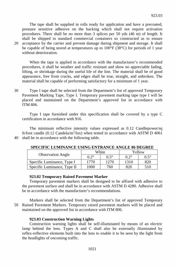
1021
The tape shall be supplied in rolls ready for application and have a precoated, pressure sensitive adhesive on the backing which shall not require activation procedures. There shall be no more than 3 splices per 50 yds (46 m) of length. It shall be shipped in standard commercial containers so constructed as to ensure acceptance by the carrier and prevent damage during shipment and storage. It shall 20 be capable of being stored at temperatures up to 100°F (38°C) for periods of 1 year without deterioration. When the tape is applied in accordance with the manufacturer’s recommended procedures, it shall be weather and traffic resistant and show no appreciable fading, lifting, or shrinkage during the useful life of the line. The material shall be of good appearance, free from cracks, and edges shall be true, straight, and unbroken. The material shall be capable of performing satisfactory for a minimum of 1 year. Type I tape shall be selected from the Department’s list of approved Temporary 30 Pavement Marking Tape, Type I. Temporary pavement marking tape type I will be placed and maintained on the Department’s approved list in accordance with ITM 806. Type I tape furnished under this specification shall be covered by a type C certification in accordance with 916. The minimum reflective intensity values expressed as 0.12 Candlepower/sq ft/foot candle (0.12 Candela/m2/lux) when tested in accordance with ASTM D 4061 shall be in accordance with the following table. 40
SPECIFIC LUMINANCE USING ENTRANCE ANGLE 86 DEGREE
Observation Angle White Yellow 0.2° 0.5° 0.2° 0.5°
Specific Luminance, Type I 1770 1270 1310 820 Specific Luminance, Type II 1000 760 820 510
923.02 Temporary Raised Pavement Marker Temporary pavement markers shall be designed to be affixed with adhesive to the pavement surface and shall be in accordance with ASTM D 4280. Adhesive shall be in accordance with the manufacturer’s recommendations. Markers shall be selected from the Department’s list of approved Temporary Raised Pavement Markers. Temporary raised pavement markers will be placed and 50 maintained on the approved list in accordance with ITM 806. 923.03 Construction Warning Lights Construction warning lights shall be self-illuminated by means of an electric lamp behind the lens. Types A and C shall also be externally illuminated by reflex-reflective elements built into the lens to enable it to be seen by the light from the headlights of oncoming traffic.
923.03
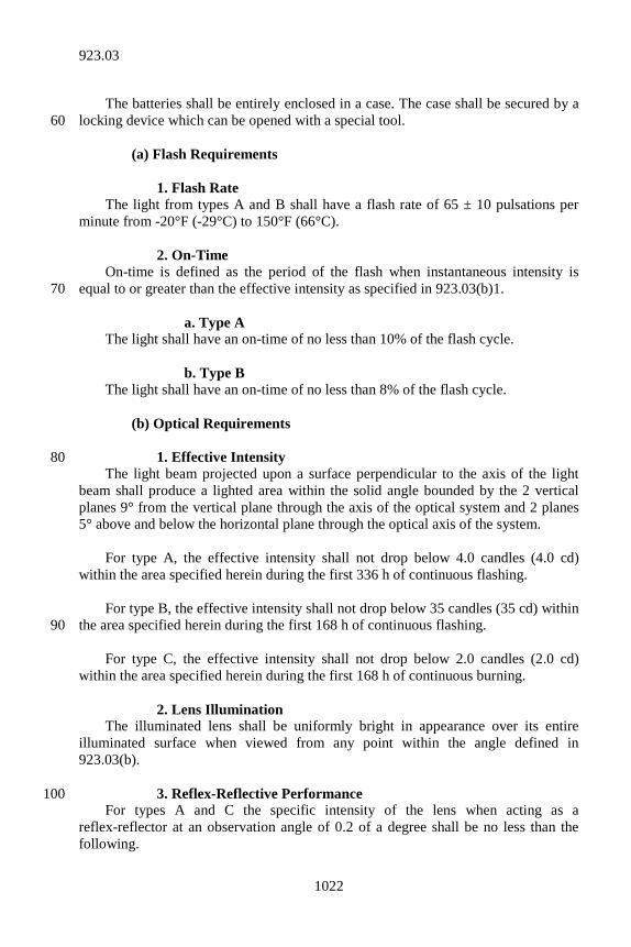
1022
The batteries shall be entirely enclosed in a case. The case shall be secured by a locking device which can be opened with a special tool. 60 (a) Flash Requirements 1. Flash Rate The light from types A and B shall have a flash rate of 65 ± 10 pulsations per minute from -20°F (-29°C) to 150°F (66°C). 2. On-Time On-time is defined as the period of the flash when instantaneous intensity is equal to or greater than the effective intensity as specified in 923.03(b)1. 70 a. Type A The light shall have an on-time of no less than 10% of the flash cycle. b. Type B The light shall have an on-time of no less than 8% of the flash cycle. (b) Optical Requirements 1. Effective Intensity 80 The light beam projected upon a surface perpendicular to the axis of the light beam shall produce a lighted area within the solid angle bounded by the 2 vertical planes 9° from the vertical plane through the axis of the optical system and 2 planes 5° above and below the horizontal plane through the optical axis of the system. For type A, the effective intensity shall not drop below 4.0 candles (4.0 cd) within the area specified herein during the first 336 h of continuous flashing. For type B, the effective intensity shall not drop below 35 candles (35 cd) within the area specified herein during the first 168 h of continuous flashing. 90 For type C, the effective intensity shall not drop below 2.0 candles (2.0 cd) within the area specified herein during the first 168 h of continuous burning. 2. Lens Illumination The illuminated lens shall be uniformly bright in appearance over its entire illuminated surface when viewed from any point within the angle defined in 923.03(b). 3. Reflex-Reflective Performance 100 For types A and C the specific intensity of the lens when acting as a reflex-reflector at an observation angle of 0.2 of a degree shall be no less than the following.
923.03
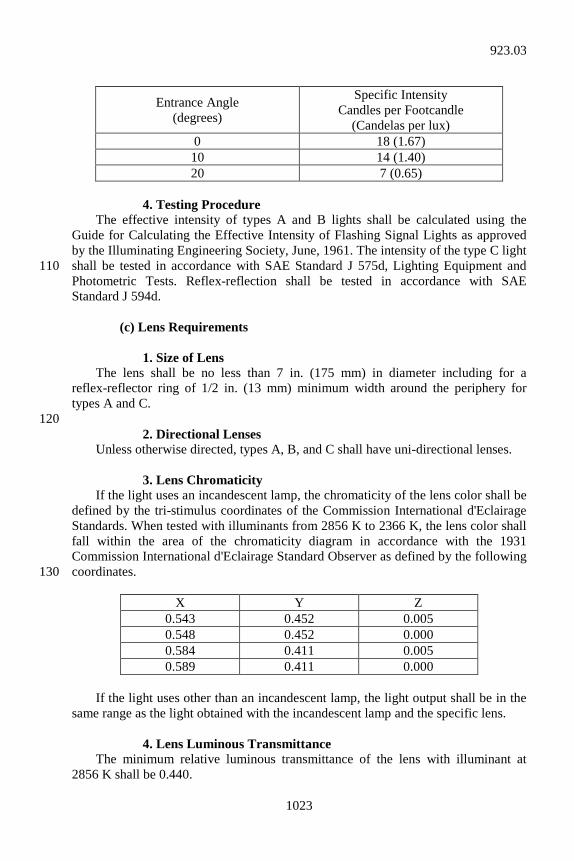
1023
Entrance Angle (degrees)
Specific Intensity Candles per Footcandle
(Candelas per lux) 0 18 (1.67) 10 14 (1.40) 20 7 (0.65)
4. Testing Procedure The effective intensity of types A and B lights shall be calculated using the Guide for Calculating the Effective Intensity of Flashing Signal Lights as approved by the Illuminating Engineering Society, June, 1961. The intensity of the type C light shall be tested in accordance with SAE Standard J 575d, Lighting Equipment and 110 Photometric Tests. Reflex-reflection shall be tested in accordance with SAE Standard J 594d. (c) Lens Requirements 1. Size of Lens The lens shall be no less than 7 in. (175 mm) in diameter including for a reflex-reflector ring of 1/2 in. (13 mm) minimum width around the periphery for types A and C. 120 2. Directional Lenses Unless otherwise directed, types A, B, and C shall have uni-directional lenses. 3. Lens Chromaticity If the light uses an incandescent lamp, the chromaticity of the lens color shall be defined by the tri-stimulus coordinates of the Commission International d'Eclairage Standards. When tested with illuminants from 2856 K to 2366 K, the lens color shall fall within the area of the chromaticity diagram in accordance with the 1931 Commission International d'Eclairage Standard Observer as defined by the following coordinates. 130
X Y Z 0.543 0.452 0.005 0.548 0.452 0.000 0.584 0.411 0.005 0.589 0.411 0.000
If the light uses other than an incandescent lamp, the light output shall be in the same range as the light obtained with the incandescent lamp and the specific lens. 4. Lens Luminous Transmittance The minimum relative luminous transmittance of the lens with illuminant at 2856 K shall be 0.440.
923.03
1024
5. Lens Material 140 The lens shall be plastic of 1 piece construction and shall meet the test requirements in accordance with SAE J 576b, except that the exposure time and condition, paragraph 3.4.3, for the purposes of this standard shall be 1 year. (d) Head and Case 1. Swivel Head If swivel capabilities as described herein are not incorporated in the device used to mount a type A or C light on a barricade or sign, the head shall be mounted on the housing in a manner permitting it to be swiveled through a minimum 90° arc in a 150 horizontal plane. If swiveling is accomplished by rotation of the head, construction shall be such that the head rotation shall not damage the wiring. 2. Case The case shall be so constructed and closed as to exclude moisture that would affect the specified operation of the light. The case shall have a weephole to allow the escape of moisture from condensation. (e) Photoelectric Controls Photoelectric controls, if provided on types A or C lights, shall keep the light 160 operating whenever the ambient light falls below 20 footcandles (215 lux). 923.04 Flashing Arrow Sign The flashing arrow sign shall be an all weather, self-contained, flashing sign designed to display the required flashing messages continuously for a minimum of 24 h without servicing. A reserve storage battery shall be provided to automatically operate the flashing arrow sign for a minimum period of 8 h if there is a power failure of the primary source. The flashing arrow sign shall have a control unit which incorporates a 170 photo-controlled transfer relay for automatic lamp intensity settings. The highest photo-controlled setting shall be full intensity for daylight operation. The lowest photo-controlled setting shall be for night-time operation and shall be 50% of full intensity when the ambient light level drops below 5 footcandles (54 lux). A minimum of 2 interim photo-controlled settings shall automatically increase or decrease the lamp intensity in direct proportion to the ambient light level. The flashing arrow sign shall have a manual control unit for adjusting lamp intensity when automatic operation becomes unsatisfactory. The manual control shall be fully adjustable between the minimum limit of 30% of full lamp voltage and 180 maximum limit of full lamp voltage.
923.04
1025
An indicator light shall be provided on the back of the sign to provide confirmation that the flashing arrow sign is operating. The indicator light shall be visible for 500 ft (150 m). (a) Solar Powered Solar power assisted units shall incorporate a target sight device and leveling mechanism to aid the user for positioning of the unit prior to use. The device shall be attached to the elevated portion of the flashing arrow sign and not to the fixed 190 support frame. The lamps shall be electronically operated by means of a solid state controller. An automatic lamp intensity regulator shall hold the lamp output constant with varying battery voltage. The control system shall incorporate a full time tracking system designed to track ambient light for 24 h a day. The control system shall adjust lamp intensity to provide maximum system efficiency. The controller shall be in a weatherproof, ventilated, lockable enclosure. The lamps shall provide amber beams with a minimum of 20° horizontal and 6° 200 vertical field of view. The minimum effective luminance within the required beam shall not be less than 1 half the effective luminance at the beam center. The battery bank shall consist of 12 v, deep cycle, batteries. The battery bank shall be of sufficient capacity to power the unit for 15 days with no assistance from the sun. A battery condition indicator and a test switch shall be provided to monitor the system’s battery charge. The batteries shall be secured in a well ventilated, weatherproof lockable housing. A low battery charge indicator which shall be visible to maintenance personnel driving past the sign shall be provided to indicate the need to recharge the batteries. The battery bank shall be at full charge when delivered to 210 the project site. The unit shall be equipped with a sign/solar panel lifting mechanism. The lifting mechanism shall be designed to safely carry the capacity of the sign’s load. The lifting mechanism shall incorporate a positive locking device to secure the panel in a raised or lowered position. Solar power assisted flashing arrow signs to be used shall be selected from the Department’s list of approved Solar Power Traffic Control Devices. 220 (b) Diesel Powered Flashing arrow sign shall be fueled by diesel fuel only. (c) AC Powered When connected to an AC electrical power source, provisions shall be made to prevent electrocution.
923.04
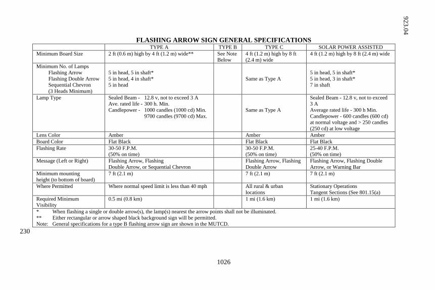
1026
FLASHING ARROW SIGN GENERAL SPECIFICATIONS TYPE A TYPE B TYPE C SOLAR POWER ASSISTED
Minimum Board Size 2 ft (0.6 m) high by 4 ft (1.2 m) wide** See Note Below
4 ft (1.2 m) high by 8 ft (2.4 m) wide
4 ft (1.2 m) high by 8 ft (2.4 m) wide
Minimum No. of Lamps Flashing Arrow Flashing Double Arrow Sequential Chevron (3 Heads Minimum)
5 in head, 5 in shaft* 5 in head, 4 in shaft* 5 in head
Same as Type A
5 in head, 5 in shaft* 5 in head, 3 in shaft* 7 in shaft
Lamp Type Sealed Beam - 12.8 v, not to exceed 3 A Ave. rated life - 300 h. Min. Candlepower - 1000 candles (1000 cd) Min. 9700 candles (9700 cd) Max.
Same as Type A
Sealed Beam - 12.8 v, not to exceed 3 A Average rated life - 300 h Min. Candlepower - 600 candles (600 cd) at normal voltage and > 250 candles (250 cd) at low voltage
Lens Color Amber Amber Amber Board Color Flat Black Flat Black Flat Black Flashing Rate 30-50 F.P.M.
(50% on time) 30-50 F.P.M.
(50% on time) 25-40 F.P.M. (50% on time)
Message (Left or Right) Flashing Arrow, Flashing Double Arrow, or Sequential Chevron
Flashing Arrow, Flashing Double Arrow
Flashing Arrow, Flashing Double Arrow, or Warning Bar
Minimum mounting height (to bottom of board)
7 ft (2.1 m) 7 ft (2.1 m) 7 ft (2.1 m)
Where Permitted Where normal speed limit is less than 40 mph All rural & urban locations
Stationary Operations Tangent Sections (See 801.15(a)
Required Minimum Visibility
0.5 mi (0.8 km) 1 mi (1.6 km) 1 mi (1.6 km)
* When flashing a single or double arrow(s), the lamp(s) nearest the arrow points shall not be illuminated. ** Either rectangular or arrow shaped black background sign will be permitted. Note: General specifications for a type B flashing arrow sign are shown in the MUTCD. 230
923.04
1027
923.05 Temporary Worksite Speed Limit Sign Assembly The temporary worksite speed limit sign assembly shall be an all weather, self-contained unit designed to display speed limit signs in accordance with the MUTCD and as shown on the plans. The signs shall be installed on frangible posts or mounted on movable stands or trailers in accordance with 910.14(f). The power source shall be capable of operating the strobe lights, without service, for the period which the sign is in effect. An on/off switch will be required. 923.06 Tubular Marker The vertically placed portion of this device shall consist of high density 240 polyethylene plastic in accordance with ASTM D 5203. The base material shall be butyl rubber in accordance with ASTM D 5900 or high impact polystyrene in accordance with ASTM D 4549. Epoxy material used to attach the base to the roadway surface shall be in accordance with the manufacturer’s recommendations. The tubular portion shall be reflectorized with high intensity reflective sheeting in accordance with 919.01(b)1 as shown on the plans. 923.07 Acceptance of Temporary Traffic Control Devices Temporary traffic control devices will be accepted by visual inspection unless otherwise indicated. 250
SECTION 924 – WELDING SUPPLIES 924.01 Welding Supplies (a) Aluminum Alloy Base Metals 1. Bare Wire Electrodes and Welding Rods Bare wire electrodes for use with the gas metal arc welding process and welding rods for use with the gas tungsten-arc welding process shall be in accordance with AWS A5.10. Tungsten electrodes for the gas tungsten-arc welding process shall be 10 in accordance with the Specifications for Tungsten-Arc Welding Electrodes, ASTM B 297 or AWS A5.12. 2. Filler Metal Filler metals to be used with particular base metals shall be as shown in the table below. Other filler metals may be used if approved. Base Metal Filler Metal 3003 to 3003 ER1100 3004 to 3004 ER4043 20 5052 to 5052 ER5356* 5083 to 5083 ER5183 5086 to 5086 ER5356* 5456 to 5456 ER5556 6061 to 6061 ER5356*
924.01
1028
6063 to 6063 ER5356* 356.0 to 6061 ER4043 356.0 to 6063 ER4043
*ER5183, ER5356, and ER5556 may be used interchangeably for these base metals. 30 Filler metals shall be kept covered and stored in a dry place at relatively uniform temperatures. Original rod and wire containers shall not be opened until time to be used. Rod and wire shall be free of moisture, lubricant, or other contaminants. Spools of wire temporarily left unused on the welding machine shall be kept covered to avoid contamination by dirt and grease collecting on the wire. If a spool of wire is to be unused for more than a short length of time, it shall be returned to the carton and the carton tightly sealed. 3. Shielding Gases 40 Shielding gases shall be welding grade or better. Shielding gas for gas metal-arc welding shall be argon, helium, or an approximate 75% helium and 25% argon mixture. Shielding gas for gas tungsten-arc welding done with alternating current shall be argon. Shielding gas for gas tungsten-arc welding done with direct current, straight-polarity, shall be helium. Hose used for shielding gases shall be made of synthetic rubber or plastic. Hose which has been previously used for acetylene or other gases shall not be used.
SECTION 925 – ITS CONTROLLER CABINET 925.01 General Requirements ITS controller cabinets shall be constructed such that it has a NEMA 3R rating. The cabinet shall be a rainproof cabinet with dimensions of 66 in. by 24 in. by 30 in. (1670 mm by 610 mm by 762 mm) in depth. The cabinet top shall be crowned or slanted to the sides to prevent standing water. The cabinet, sunshields, doors, and all panels shall be fabricated of 1/8 in. (3 mm) minimum thickness aluminum. The only exception to this aluminum 10 thickness is the detector rack, which shall be fabricated of 0.090 in. (2.3 mm) thickness aluminum. All exterior seams for the cabinets and doors shall be continuously welded. All exterior welds shall be ground smooth. All edges shall be filed to a radius of 5/16 in. (8 mm) minimum. The cabinet, sunshields, doors, and all panels shall be fabricated from aluminum sheet in accordance with ASTM B 209 (ASTM B 209M), 5052-H32 aluminum sheet. Welding on aluminum shall be done by the gas metal arc welding process using 20 bare aluminum welding electrodes. Electrodes shall be in accordance with AWS A5.10 for ER5356 aluminum alloy bare welding electrodes.
925.01
1029
Procedures, welders, and welding operators for welding on aluminum shall be qualified in accordance with the requirements of AWS B3.0, “Welding Procedure and Performance Qualification”, and to the practices in accordance with AWS C5.6. Each aluminum surface shall be finished in accordance with Military Specification MIL-A-8625F(1), “Anodic Coatings for Aluminum and Aluminum Alloys”, type II, class I coating, except that the anodic coating shall have a minimum 30 thickness of 0.0008 in. (0.02033 mm) and a minimum coating weight of 0.04 mg/mm2. The anodic coating shall be sealed in a 5% aqueous solution of nickel acetate (pH 5.0 to 6.5) for 15 min at 206°F (97°C). The anodized coating shall be silver in color. Prior to applying the anodic coating, the cabinets shall be cleaned and etched as follows: (a) Clean by immersion in inhibited alkaline cleaner such as Oakite 61A or
Diversey 909, or equivalent, 45 to 60 grams per liter, 160°F (71°C) for 5 min.
(b) Rinse in cold water. 40 (c) Etch in a solution of 11 g of sodium fluoride, plus 30 to 45 g of sodium
hydroxide per liter of distilled water at 140 to 150°F (60 to 65°C) for 5 min.
(d) Rinse in cold water. (e) Dissolve in a 50% by volume nitric acid solution at room temperature
for 2 min. (f) Rinse in cold water. The cabinet shall have single front and rear doors equipped with a lock. The doors shall use a Corbin lock No. 2, and each cabinet shall be equipped with 2 No. 2 50 keys. When each door is closed and latched, the door shall be locked. Keys shall be removable in both the locked and unlocked positions. The door handles shall have provision for padlocking in the closed position. The handle shall have a minimum length of 7 in. (180 mm) and shall be provided with a 5/8 in. (16 mm), minimum, steel shank. The handle shall be fabricated of cast aluminum or stainless steel. The cabinet door frame shall be designed so that the latching mechanism shall hold tension on and form a firm seal between the door gasket and the door frame. The cabinet shall not include a police door nor have provisions for a police door. 60 The latching mechanism shall be a 3-point cabinet latch with nylon rollers. The center catch and pushrods shall be zinc-plated or cadmium-platted steel. Pushrods shall be turned edgewise at the outer supports and shall be 1/4 by 3/4 in. (6 by 19 mm), minimum. The nylon rollers shall have a minimum diameter of 3/4 in. (19 mm) and shall be equipped with ball bearings. All cadmium plating shall be in accordance with the Society of Automotive Engineers, SAE-AMS-QQ-P-416, “Plating, Cadmium (Electrodeposited)”. All zinc
925.01
1030
plating shall be in accordance with ASTM B 633-98E1, “Electrodeposited Coatings of Zinc on Iron and Steel”. 70 The door’s hinging shall be 3 or 4 bolt butt hinges. Each hinge shall have a fixed pin. Doors larger than 22 in. (60 mm) in width or 6 sq ft (0.5574 m2) in area shall be provided with catches to hold the door open at both 90° and 180°, ± 10°. The catches shall be 1/3 in. (8 mm) diameter, minimum, plated steel rods. The catches shall be capable of holding the door open at 90° in a 56 mi/h (90 km/h) wind at an angle perpendicular to the plane of the door. Door hinges, pins, and bolts shall be made of stainless steel. The hinges shall be bolted to the cabinet. The hinge pins and bolts shall not be accessible when the door is closed. 80 Door gaskets shall be provided on all door openings and shall be dust tight. Gaskets shall be permanently bonded to the metal. The mating surface of the gasket shall be covered with a silicone lubricant to prevent sticking to the mating surface. Both cabinet doors shall have louvered openings and shall provide ventilation. A filter shall be provided over the louvers and shall include an aluminum filter cover secured with a spring loaded latch as shown on the plans. The filter shall be 12 by 16 by 1 in. (300 by 400 by 25 mm). Two spare filters shall be provided with each cabinet. 90 The cabinet shall be provided with 2 metal lifting eyes to be used when placing the cabinet on the foundation. Each eye shall have a minimum diameter of 3/4 in. (19 mm) and shall be capable of lifting 990 lbs (450 kg). Machine screws and bolts shall not protrude beyond the outside wall of the cabinet. 925.02 Model Approval Each cabinet model shall be approved prior to use. A period of evaluation will commence when the Department receives a preliminary product evaluation form 100 accompanied by the product brochure, detailed electrical schematics, and cabinet assembly drawings. The Operations Support Division will advise the manufacturer or vendor, in writing, of the date and location to deliver the cabinet for which model approval is requested. Electrical schematics for the cabinet, cabinet assembly drawings, and parts lists shall be furnished with the controller when it is submitted to the Operations Support Division for evaluation and testing. A list of approved models will be maintained by the Department. Only models from the Department’s list of approved ITS Controller Cabinets in effect as of the date of letting, or as otherwise specified, shall be used on the contract. Continued 110 failure and repeated malfunctions of an approved controller or control equipment shall be cause to remove that model from the Department’s list of approved products. A design change to an approved model or cabinet will require re-submittal of the
925.02
1031
model for testing, evaluation, and approval. Permanent addition or removal of component parts or wires will be considered to be a design change. 925.03 Warranty The cabinet, sunshields, doors, and all other exterior surfaces shall carry a 5 year warranty against all material imperfections. All other electrical components and wiring shall carry a 3 year warranty against all imperfections in workmanship or 120 materials. 925.04 Cabinet Accessories The following accessories shall be furnished and installed with each ITS cabinet. (a) Rack Frame Assembly The cabinet shall come equipped with standard Electronic Industries Alliance 19 in. (480 mm) rack frame assembly. The rack frame assembly shall have standard Electronic Industries Alliance vertically spaced threaded holes for attachment of equipment, mounting angles, and shelves. Frame mounting of equipment and shelves 130 shall be available on both door sides of the cabinet. (b) Equipment Shelves The equipment rack shall be furnished with 2 adjustable equipment shelves. A 3 in. (75 mm) hole shall be provided in each shelf. The hole shall be fitted with a nylon snap bushing liner with an outside diameter of 3.16 in. (80 mm), inside diameter of 2 1/2 in. (63 mm) and a height of 0.72 in. (18 mm). The shelves shall be constructed of an aluminum screen tack welded between the shelf bottom and upper ribs. The shelves shall be capable of being moved in any location. 140 (c) Sunshield An aluminum panel sunshield shall be mounted on standoffs on the top and each side of each cabinet. (d) Side Panels Two aluminum side panels shall be provided and mounted on the Electronic Industries Alliance rack parallel to the cabinet sides. One panel shall be designated as the “power distribution panel” and the other panel shall be designated the “heater panel”. 150 (e) Data Pocket The data pocket is to be large enough to hold several drawings, a maintenance log notebook, and several pieces of reference material but not so large as to contact any of the installed equipment. (f) Equipment Labels The labels shall have a non-reflective, exterior grade, low glare matte surface finish applied to flexible ABS plastic. The labels shall be black with white lettering
925.04
1032
and have an engraving depth of 0.002 to 0.003 in. (0.0508 to 0.0762 mm). Labels shall conform to the designations on the cabinet diagrams. 160 (g) Primary Power Terminal Block A power distribution terminal block shall be mounted on the power distribution panel. The power distribution block shall be a mechanical 3 pole connector. The connectors for the incoming power shall be able to accept wire sizes between 12 AWG and 2/0 AWG. The load side connectors shall be able to accept wire sizes between 14 AWG and 4 AWG. The rating of the connector shall be 195 amps per pole. The connector elements shall be made from a tin plated, high conductivity aluminum alloy and insulated with high strength thermoplastic housing with a relative temperature index of 260°F (125°C). It shall be rated 600 volt, AL9CU. The 170 dimensions shall be 4 by 5.2 by 3.23 in. (100 by 132 by 82 mm) high. The block shall come with 1 polycarbonate safety cover per pole. Mounting screws shall be No. 10, 0.19 in. (4.83 mm) diameter. The block shall be UL Listed. The terminal block shall be a Burndy Model BDB-11-2/0-3. (h) Ground Lug The ground lug mounted on the power distribution panel shall be a heavy-duty 1-hole ground lug, manufactured from electrolytic copper tubing and strip stock. UL Listed and CSA certified for stranded CU wire and for 600 volts. Wire range: 6 AWG to 14 AWG. Bolt size: #10. Tang length shall be 1/2 in. (13 mm). Width 180 shall be 5/16 in. (8 mm). The lug shall be an Ilsco Model SLUH-35. (i) Ground Bus Rated to 600 volts. 12 taps per ground bar suitable for wire ranging from 6 AWG to 14 AWG. Main ground connection wire range from 4 AWG to 14 AWG. The ground bar shall be 5 15/16 in. by 3/4 in. by 11/32 in. (150 mm by 19 mm by 9 mm). It shall be UL Listed. The ground bus shall be an Ilsco Model D167-12. (j) Transient Voltage Surge Suppression The transient voltage surge suppression, TVSS, shall have individually fused 190 suppression modes, thermal cutout, operational indictors (LED) to indicate loss of protection or circuit fully operational, including neutral-to-ground, AC tracking filter with EMI/RFI filtering up to -50dB from 100 kHz to 100 MHz, and a short circuit current rating of 200,000 rms symmetrical amperes. Surge suppression shall be provided for each mode (L-N or L-L, L-G, N-G). The TVSS shall be UL 1449 Second Edition Listed and UL 1283 Recognized. The TVSS shall have 120/240 volt split phase service voltage and dry contacts for each phase providing a summary alarm. The contacts are terminated in a DB-9 connector. The surge capacity shall be 80 kA/phase. The response time shall be less than 200 1/2 nanosecond. The unit shall withstand 5000 category C3 impulses with less than 10% drift. It shall be suitable for use under non-condensing relative humidity range of 0 - 95%. The suppressed voltage rating shall be 330 volts L-N, L-G, N-G and 700 volts L-L. Operating frequency: 47 - 63 Hz. Operating temperature: -40°F to 140°F
925.04
1033
(-40°C to +60°C). External mount NEMA 1 standard enclosure. Standard size: 6 in. by 6 in. by 4 in. (150 mm by 150 mm by 100 mm) depth. Weight: 8 lbs (3.63 kg). The TVSS shall be UL 1449 Second Edition Listed, 1283 Recognized and CUL. The unit shall be an Advanced Protection Technologies Model TE/1XF. (k) Load Center Main Breaker 210 The load center main breaker shall be enclosed 2 pole, 240/240 volt AC, 60 amp. It shall have a 10,000 rms symmetrical ampere short circuit current rating. The circuit breaker enclosure shall be a Square D, Model QO2TR. (l) Load Center Panelboard The panelboard shall be a 120/240 volt AC, 600 volt, 8 pole panelboard. The panelboard shall have a neutral bus bar with 3 10 amp breakers, four 15 amp breakers and 1 spare. The load center shall be main lug only Square D, Model QO. The circuit breakers shall be Square D, Model QO. 220 (m) GFI Duplex Receptacle The convenience receptacle shall be a duplex, 3-prong, NEMA type 5-15R grounding type outlet and shall be in accordance with UL Standard 943. (n) Duplex Receptacle A standard 3-prong, NEMA type 5-15R grounding type outlet shall be mounted on the power distribution panel. (o) Terminal Strip Surge Protector One 48 in. (1,220 mm) surge protected terminal strip with ten 15A outlets shall 230 be furnished and installed. The terminal strip shall have a low profile aluminum housing measuring 1 1/2 by 1 3/16 in. (38 by 30 mm) and have a 14/3 SJT cord and a NEMA 5-15P plug. The spacing between the outlets shall be 4 in. (100 mm) and the grounding pin shall be positioned so that it is oriented toward the bottom of the cabinet. The unit shall be in accordance with UL Standard 1449 with a 330 volt clamping level. The unit shall be a Wiremold Model 4810BCS with a 6 ft (1.8 m) cord. (p) Door Open Switches 240 Four dry-contact, 1-pole-form-C (single-pole, double throw), switches shall be provided and installed. Switch poles are to be electrically isolated. One set of switches shall be rated for 5 amp at 120 volt AC to be used to automatically turn the lights off when both cabinet doors are closed. The other set shall be rated for 1 amp at 5 volt DC and are to be used to send a door open alarm. The switches shall be Omron part No. Z-15GQ-B. (q) Light Switch A toggle switch 20 amp, DPDT with 1/8 in. (3 mm) diameter hole in solder lugs shall be provided and installed that will manually switch on the lights regardless of 250
925.04
1034
the door switch position. The switch shall be McGill Mfg. Co., part No. 0121-7013 or Eaton part No. 7803K13. (r) Lamp Holders Each cabinet shall be furnished with 2 lamp holders. The UL Listed device shall have a medium phenolic base measuring 1.9 by 1.9 by 1.5 in. (48 by 48 by 38 mm) and rating 660 watt and 250 volt. The lampholder shall be a Leviton Model 9063. (s) Lamps Each lamb holder shall be provided with a 100 watt rugged service incandescent 260 bulb. (t) Circulating Fans Three 110 cu ft/min (3 m3/min), 4.7 by 4.7 by 1.5 in. (120 by 120 by 38 mm) cooling fans shall be installed within the cabinet to circulate internal air. The fans shall have an allowable ambient temperature range of 14°F to 158°F ( - 10°C to +70°C) and a voltage rating of 115 volt. The fan casings shall be aluminum alloy. The impeller shall be UL94V-O reinforced plastic. The fans shall have ball bearings and an impedance protected, shaded pole induction motor. The fans shall not be exposed or routed to the external environment. The environmental controller shall 270 control fan operation. The fans shall activate at 80°F (27°C). The fans shall be NMB Model 4715FS-12T-B50-D00. (u) Enclosure Heaters Two 250 watt ceramic insulated strip heaters shall be furnished and installed in the cabinet to protect against condensation damage and to keep the electronic components above freezing in the winter. The strip heaters shall have a seamless stainless steel sheath with ceramic element support and magnesium oxide packing. The environmental controller shall control enclosure heater operation. Heating strips shall not be installed on either door. The heaters shall be 8 in. (200 mm) long by 280 1 1/2 in. (38 mm) wide and shall have 2 wire terminals. The strip heaters shall be UL Recognized. The heaters shall be Hotwatt Model CS-8. (v) Heater Relays Two solid state SPST-NO heater relays shall be installed on the power distribution side panel. Load current range 0.04 to 25 amp, 1-cycle surge 250 amp peak. Rated for 120 volt AC and UL Recognized. (w) Thermostats The cabinet shall be furnished with 2 thermostats installed. One thermostat shall 290 activate the enclosure heaters and circulating fan with the internal cabinet temperature goes below 35°F (2°C). The other thermostat shall activate the 2 circulating fans at the top of the cabinet when the internal cabinet temperature goes above 80°F (27°C). The thermostats shall be Thermodisc, Type AL-1.
925.04
1035
(x) Detector Card DIN Rail Terminal Blocks Double-deck compression clamp DIN rail terminal blocks shall be hard wired to the Canoga Card Racks. A total of 64 terminal blocks shall be mounted to an aluminum panel that is secured to the Electronic Industries Alliance rack. The terminal blocks shall allow wires between 24 AWG and 10 AWG. Each measures 300 2.5 in. by 0.2 in. (65 mm by 6 mm). The terminal blocks shall be the Entretec part number 011527122 type M 4/6 D2. (y) I/O Module An isolated 8-Bit digital input module shall be provided and installed. It shall have 6 fully isolated inputs and 2 share common ground inputs. High voltage inputs. Logic levels: LOW +1.0 volt DC max, HIGH +3.5 to +30 volt DC. Input impedance: 3 kohm. Input isolation: 3000 vrms. Power consumption: 0.4 watt. Operating temperature: 14°F to 158°F (-10°C to 70°C). The I/O module shall be a Measurement Computing, Model CB-7052. 310 (z) Detector Card Rack The detector card rack shall be as shown on the plans. (aa) Padlocks Padlocks shall be classified as a high security padlock with hardened shackles, laminated body, a minimum 4 pin cylinder, and come complete with a weather cover to protect the lock body and cylinder from sand, dirt, water, and ice. A wafer cylinder shall not be used. Keys shall not be provided with each padlock supplied. All padlocks shall be keyed alike and shall be keyed identical to the keys currently in 320 use by the Department. The main body width of the padlock shall not exceed 3 in. (75 mm) and shall have a shackle length of 2 1/4 to 3 3/4 in. (56 to 94 mm) and a shackle diameter of 5/16 in. (8 mm). For padlock information, contact the ITS Operations Engineer. (bb) Other Cabinet Equipment In addition to the equipment specified above, the cabinet shall be furnished with all ancillary equipment, brackets, wiring ducts, hardware, etc, as is necessary to provide a neat and finished appearance. These items along with all associated cables, connectors, wiring, etc. shall be labeled on the required submittal drawings. 330 925.05 Cabinet Wiring All conductors used in ITS cabinet wiring shall be in accordance with the following color-code requirements. (a) The AC neutral conductor of a circuit shall be identified by a
continuous white or natural gray color. (b) The equipment grounding conductor shall be identified by a continuous
green color or by a continuous green color with 1 or more yellow 340 stripes.
925.05
1036
(c) The ungrounded conductors shall be identified by any color not
specified in a or b above. All wire shall be type THHN with color and gage as shown on the plans with the exception of the microloop card rack wiring which will be 2-pair twisted with a shield and plentium rated. Connectors used for interconnecting various portions of circuits together shall be 350 designed and constructed for the application involved. Connectors shall be designed to provide positive connection of all circuits, and easy insertion and removal of mating contacts. Connections shall be permanently keyed to prevent improper connection of circuits. 925.06 Drawings The Contractor shall provide 3 sets of cabinet wiring diagrams. The diagrams shall be non-proprietary and shall identify all circuits, as installed, in such a manner as to be readily interpreted. In addition, 3 cabinet drawings shall be provided with each cabinet to show the component layout in elevation views from the front and 360 rear. An elevation of both aluminum side panels shall also be shown. Elevation views are to be detailed down to the level showing mounting brackets and wiring ducts. All other mounting hardware and cable ties need not be shown. All cables and connectors shall be clearly labeled. Any data sheets for internal cabinet components that have been made available by the manufacturer shall also be provided. One set of the wiring diagram and cabinet drawing shall be placed in a heavy-duty side-opening clear plastic pouch and inserted into the data pocket. The pouch shall be of such design and material that it provides adequate storage and access to the drawings. The other 2 sets of drawings shall be delivered to the attention of the ITS Field Engineer. 370
SECTION 926 – MISCELLANEOUS MATERIALS 926.01 Flexible Delineator Posts Flexible delineator posts shall be made of high density polyethylene plastic in accordance with ASTM D 5203. The post shall be straight along its center line and have a smooth surface free from cracks, flaws, seams, laps, blisters, and edges affecting the strength, durability, or appearance. The cross section width shall not exceed 6 in. (150 mm). The reflective sheeting on the post shall be in accordance with 919.01(b) and 10 shall have minimum dimensions of 3 by 8 in. (75 by 200 mm). Reflective sheeting shall be applied directly to the post and protected in a manner that minimizes damage to the sheeting upon impact. The color of the post and the reflective sheeting shall match the color of the adjacent edgeline.
925.06
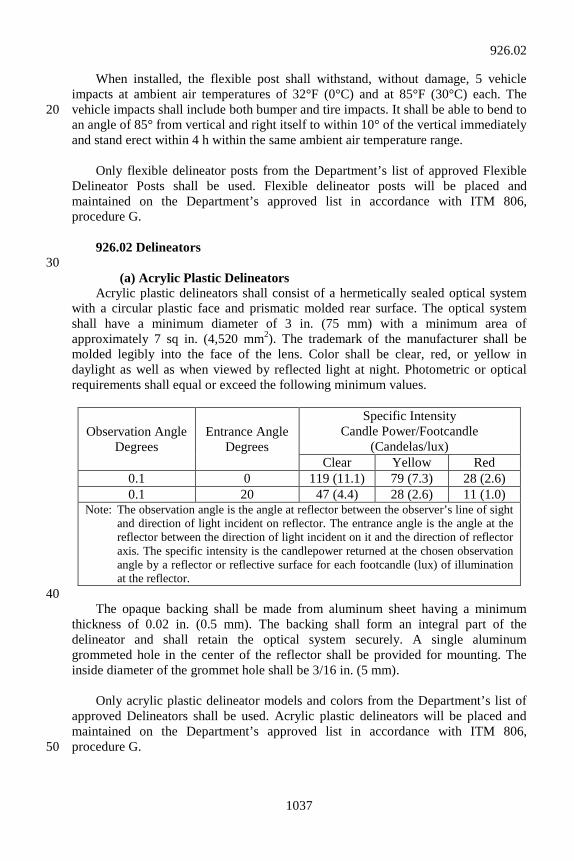
1037
When installed, the flexible post shall withstand, without damage, 5 vehicle impacts at ambient air temperatures of 32°F (0°C) and at 85°F (30°C) each. The vehicle impacts shall include both bumper and tire impacts. It shall be able to bend to 20 an angle of 85° from vertical and right itself to within 10° of the vertical immediately and stand erect within 4 h within the same ambient air temperature range. Only flexible delineator posts from the Department’s list of approved Flexible Delineator Posts shall be used. Flexible delineator posts will be placed and maintained on the Department’s approved list in accordance with ITM 806, procedure G. 926.02 Delineators 30 (a) Acrylic Plastic Delineators Acrylic plastic delineators shall consist of a hermetically sealed optical system with a circular plastic face and prismatic molded rear surface. The optical system shall have a minimum diameter of 3 in. (75 mm) with a minimum area of approximately 7 sq in. (4,520 mm2). The trademark of the manufacturer shall be molded legibly into the face of the lens. Color shall be clear, red, or yellow in daylight as well as when viewed by reflected light at night. Photometric or optical requirements shall equal or exceed the following minimum values.
Observation Angle Degrees
Entrance Angle Degrees
Specific Intensity Candle Power/Footcandle
(Candelas/lux) Clear Yellow Red
0.1 0 119 (11.1) 79 (7.3) 28 (2.6) 0.1 20 47 (4.4) 28 (2.6) 11 (1.0)
Note: The observation angle is the angle at reflector between the observer’s line of sight and direction of light incident on reflector. The entrance angle is the angle at the reflector between the direction of light incident on it and the direction of reflector axis. The specific intensity is the candlepower returned at the chosen observation angle by a reflector or reflective surface for each footcandle (lux) of illumination at the reflector.
40 The opaque backing shall be made from aluminum sheet having a minimum thickness of 0.02 in. (0.5 mm). The backing shall form an integral part of the delineator and shall retain the optical system securely. A single aluminum grommeted hole in the center of the reflector shall be provided for mounting. The inside diameter of the grommet hole shall be 3/16 in. (5 mm). Only acrylic plastic delineator models and colors from the Department’s list of approved Delineators shall be used. Acrylic plastic delineators will be placed and maintained on the Department’s approved list in accordance with ITM 806, procedure G. 50
926.02
1038
(b) Reflective Sheeting Delineators Reflective sheeting delineators shall consist of reflective sheeting affixed to an aluminum backing material. The white delineator shall be 3 by 8 in. ± 1/8 in. (75 by 200 mm ± 3 mm). The yellow delineator shall be 5 by 5 in. ± 1/8 in. (125 by 125 mm ± 3 mm). The backing material shall be in accordance with 919.01(a) except the minimum thickness shall be 0.064 in. (1.6 mm). Reflective sheeting shall be in accordance with 919.01(b). There shall be 2 mounting holes, 3/16 in. (5 mm) in diameter, with one at the top 60 and one at the bottom. The holes shall be 6 in. ± 1/16 in. (150 mm ± 2 mm) center to center and in the corners of the square units. Completed delineators shall be dip coated with a high gloss clear finish coat as specified and supplied by the sheeting manufacturer. The finished units shall be clean cut, sharp, and have essentially a plane surface. Material furnished under this specification shall be covered by a type C certification in accordance with 916. (c) Barrier Delineators 70 The delineators shall consist of a transparent acrylic plastic face, herein referred to as the lens, and an opaque back fused to the lens under heat and pressure around the entire perimeter to form a unit permanently sealed against dust, water, and water vapor. The reflector lens shall be colorless. The lens shall consist of a smooth front surface free from projection or indentations other than for purposes of identification or orientation of the reflector. The rear surface shall have a prismatic configuration such that it will effect total internal reflection of light. The manufacturer’s trademark shall be molded legibly into the face of the lens. 80 The reflector lens, having a minimum effective reflex area of 6.5 sq in. (4,194 mm2), shall be methyl methacrylate in accordance with Federal Specification LP-380C, type 1, Class 3. Photometric or optical requirements shall equal or exceed the minimum values in 926.02(a). Only barrier delineator models and colors from the Department’s list of approved Delineators shall be used. Barrier delineators will be placed and maintained on the Department’s approved list in accordance with ITM 806, procedure G. 90 (d) Temporary Barrier Delineator Temporary barrier delineators shall consist of a type III sheeting in accordance with 919.01(b)1 affixed to a reboundable substrate. The delineator shall be 8 by 12 in. (200 by 300 mm) vertically mounted. The mounting bracket used to affix the delineator to the barrier shall not be more than 3 in. (75 mm) vertical.
926.02
1039
926.03 Alternate Material Guardrail Blocks Non-timber blockouts shall be dimensioned as tested and shall be used with the type of guardrail as tested in accordance with NCHRP 350. Blockouts shall be 100 accompanied by a certification from the manufacturer stating the blockouts furnished have the same chemistry, mechanical properties, and geometry as those certified to have passed the NCHRP 350 crash test and have been certified by the FHWA to be acceptable for use on NHS facilities. Alternate material blockouts meeting the criteria may be used interchangeably with timber blockouts as long as the line and grade of the face of the guardrail is true to that shown on the plans.
926.03