mosaic-grouting monitoring by ground-penetrating radar · mosaic-grouting monitoring by...
TRANSCRIPT

Structura/ Ana/ysis of Historica/ Constructions - Modena, Lourenço & Roca (eds) © 2005 Tay/or & Francis Group, London, /SBN 04 1536379 9
Mosaic-grouting monitoring by ground-penetrating radar
P. Côte & X. Dérobert Laboratoire Central des Ponts et Chaussées, Bouguenais, France
A. Miltiadou-Fézans Directorate ofTechnica/ Researchfor Restoration, Hellenic Ministry ofCu/ture, Athens, Greece
N. Delinikolas 1 st Ephoria of Byzantine Antiquities, Hellenic Minislly of Cu/ture, Athens, Greece
N. Minos Direclorate for lhe Conservation of Ancient Monuments, Hellenic Minisfly of Cu/ture, Athens, Greece
ABSTRACT: Due to the 1999 Athens earthquake, both the masonry structure and the mosaics ofthe Katholikon of Dafni 's Monastery have suffered severe damages. In order to design the appropriate intervention scheme for mosaic conservation, first for the detection and mapping of delaminated mosaic's areas, and second for the monitoring the movement of the grout during injection, using a non-destructive testing such as groundpenetrating radar, presents a great interest. Two experimental studies have been realized on the mosaics. The first one concerns GPR mapping on some mosaics in-situ, in order to find out the exact location of doubtful zones including delamination, changes of structures (i.e. recent repairs) or buried heterogeneities. The second one is foeused on the GPR monitoring of mosaic grouting. Thus, a physical model has been built, including known voids in order to develop a survey methodology. Results show that one can follow the grouting spreading inside the physical model.
INTRODUCTlON
The Katholikon (church) of Oafni 's Monastery is one of the most important monuments of the middle-byzantine period (Millet 1899, Bouras 1998, Delinicolas et aI. 2003), already inscribed in the World Heritage List of UNESCO and well known for its exeellent mosaics from II th century. Due to the 1999 Athens earthquake both the masonry structure and the mosaics have suffered severe damages (MiltiadouFezans et aI. 2003). In order to design the appropriate intervention scheme, the detection and mapping of mosaic 's areas, which have been detached from the masonry, using non destructive testing, presents a great interest. On the other hand, as the application of injeetion techniques by means of suitable hydraulic grouts is often used in the case of detached mural mosaies, the possibility of using non destructive procedures to monitor the movement of the grout during injection could be very use fuI in order to assure that the voids are filled without endangering the mosaics ' substrata.
Non-Destructive Testing (NOT) methods have begun to be eommonly used, for historical buildings '
401
investigations, for only few years. Old masonry struetures from civil engineering, sueh as bridges, present similar pathologies than masonry historical buildings. That is why NDT can partieipate actively to the evaluation of such structures (Colla et aI. 1997, McCann & Forde 2001 , Binda et aI. 2003).
The Ground-Penetrating Radar (GPR) is a very usefuI technique, lying in a high-speed acquisition rate. GPR is mainly dedicated to the detection and location of hidden heterogeneities in the structures at depths from 5- 6 em (at very high frequencies, over I GHz) to up to a meter (at lower frequencies, about 500 MHz) (Maierhofer & Leipold 200 I).
For particular cylindrical structures, like pillars, NOT tomography technique have been developed in order to obtain qualitative information, while mapping a 20-transversal section, on the detected heterogeneities (Valle et aI. 1999, Flint et aI. 1999).
In the present application, two experimental studies have been realized on Byzantine mosaics. The first one concerns GPR mapping on some mosaics in-situ, related with their very near bearing-structure, in order to locate doubtful zones including delamination,
changes of structures (i.e. recent repairs) or buried heterogeneities. The second one is focused on the GPR monitoring ofmosaic grouting.
2 MOSAIC MAPPING
2.1 Presentation of the problem
Many of mosaics have been damaged due to earthquakes that occurred throughout the history of the monument. In the masonry drums ofthe dome and the arches, that support squinches, there are many cracks visible on the surface.
The load bearing elements of the church are three-layered masonry walls, consisting of two stone masonry layers and a zone in-between with loose fill ing material. The mosaics are attached to the walls by mortar, the quality ofwhich has a great importance for an adequa te sustainability.
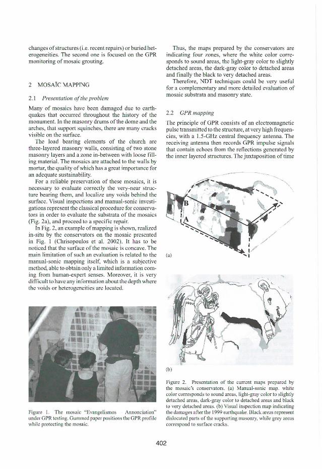
For a reliable preservation of these mosaics, it is necessary to evaluate correctly the very-near structure bearing them, and localize any voids behind the surface. Visual inspections and manual-sonic investigations represent the classical procedure for conservators in order to evaluate the substrata of the mosaics (Fig. 2a), and proceed to a specif ic repair.
In Fig. 2, an example of mapping is shown, realized in-situ by the conservators on the mosaic presented in Fig. I (Chrisopoulos et aI. 2002) . It has to be noticed that the surface ofthe mosaic is concave. The main limitation of such an evaluation is related to the manual-sonic mapping itself, which is a subjective method, able to obtain only a limited information coming from human-expert senses. Moreover, it is very difficult to have any information about the depth where the voids or heterogeneities are located .
Figure I. The mosaic "Evangelismos - Annonciation" under GPR testing. Gummed paper positions the GPR profile while protecting the mosaico
Thus, the maps prepared by the conservators are indicating four zones, where the white color corresponds to sound areas, the light-gray color to slightly detached areas, the dark-gray color to detached areas and finally the black to very detached areas.
Therefore, NDT techniques could be very useful for a complementary and more detai led evaluation of mosaic substrata and masonry state.
2.2 GPR mapping
The principie of GPR consists of an electromagnetic pulse transmitted to the structure, at very high frequencies, with a 1. 5-GHz central frequency antenna. The receiving antenna then records GPR impulse signals that conta in echoes from the reflections generated by the inner layered structures. The juxtaposition of time
----- --
(b)
Figure 2. Presentation of the current maps prepared by the mosaic 's conservators. (a) Manual-sonic map. white color corresponds to sound areas, light-gray color to slightly detached areas, dark-gray color to detached areas and black to very detached areas. (b) Visual inspection map indicating the damages afier the 1999 earthquake. Black areas represent dislocated parts of the supporting masonry, while grey areas correspond to surface cracks.
402

signals enables to construct a time-section - or GPR profile - (the time unit is the nanosecond), presented with a false gray-color scale, related to the amplitude ofthe signals, and which gives information ofthe geometry ofthe investigated structure (an example of GPR profile is given further in Fig. 4).
Thanks to specific processing from parallel GPR profiles (shown in the dotted area, from Fig. 2a, where arrows positioning the GPR profiles), maps can be constructed from chosen trenches ofthe investigated medium. Although, a high central-frequency GPR-antenna has been used (1.5 GHz), the expected information, delamination or recent repair just behind the mosaic, is located in the GPR surface echo.
Thus, the energy ofthe first peak ofparallel profiles has been summarized in a map after a subtraction of a calibration signal recorded in a supposed sound area (Fig.3).
NDT mapping enables to locate areas, which can be considered as more or less different from the chosen calibration zone. Processing is automatic and focuses the human factor on his competence: the interpretation and evaluation ofthe masonry structure.
Thus, one can roughly discriminate two main areas, a lighter one in the upper part of the map (above the
Rccent rt:pair with rehars
Calibratioll afl.!a
Figure 3. Horizontal GPR mapping ofthe mosaic presented in Fig. I. Dark areas correspond to highest differences from the calibration zone.
1
2 3
w 4 :lO F 5
6 7 Q
DISTANCE [M ETERI
1.0 20
Figure 4. Vertical GPR profile done on the repaired area (down to top).
profile B, in Figs 2a and 3) which properties are elose to the ones of the calibration area, and a darker one in the bottom part which could correspond to a different type of structure. Moreover, some details can be seen through the variations of gray-Ievel. These two kind of structures can also been identified on the vertical GPR profile (Fig. 4); the upper part, over I-m high, shows large deep-echoes which indicate a quite different structure behavior than the lower part of the profile.
Concerning the lower structure, between profiles A and B, one can notice some dark area around ofthe calibration zone, which shape (dotted line in Fig. 3) could correspond to the one of the detached areas, detected by manual-sonic sounding (in Fig. 2a).
Moreover, in the middle upper part ofthe GPR map, an area reinforced by a mesh of bars, corresponding to a recent repair, has been localized in a considered sound area (in Fig. 2a). From the horizontal GPR profiles, which were used for the map Fig. 3, five vertical bars have been detected, lO-em spaced and about 80-cm long. Similarly, vertical GPR profiles have shown ten horizontal bars, lO-em spaced and about 40-cm long (Fig. 4). lt has to be noticed that although the date and the area of the repair was known, the existence of steel reinforcements was not reported in the relevant reports.
Thus, the gray-Ievel scale GPR mapping should offer a complementary instrument in the hands ofthe mosaic's conservators in order to discriminate various leveis of zoning. The evaluation of sue h approach is still in progresso
A second example, realized 011 the Virgin Birth mosaic, is illustrated in Fig. 5. The manual-sonic map is compared to the GPR reflectivity map. In this case, the contrasts observed with both methods are smaller than in the previous case (Annonciation mosaic). One of the advantages of the GPR technique comes from the fact that it is possible to compare severa I mosaics using the same procedure. Then, one could elassify the whole set ofmosaics ofthe church with the typology based on the observed degradation . Indeed, the relative subjectivity of the manual-sonic classification do not authorize such comparison between several mosaics.
3 GROUTING CONTROL
3.1 Physicalmodel
The second approach ofGPR investigation has focused on monitoring weak-structured mosaic grouting. Thus, a physical model has been built with pieces of thick lime plaster put together with lime mortar, ineluding known void areas in order to develop the survey methodology and define the performances and limits that one can expect.
403

(a)
Calibration area
(b)
Figure 5. Mosaic of the Virgin Birth. (a) Manual-sonic map prepared by the mosaic's conservators. (the false-gray leveI scale corresponds to the one Fig. 2). (b) Vertical GPR map. Dark areas correspond to highest differences from the calibration zone.
The model has been constructed in the Laboratory of the Directorate for the Conservation of Ancient Monuments, in order to be used for the observation of the efficiency of grouting. It consists of two paralleI lime mortar plates (42 x 53 cm, 3,5-4,5 cm thick), which are not completely connected (adjacent).
Before the connection ofthe edges ofthe two plates of the specimen, the upper one was cut into smaller pieces, in order to create a non-uniform surface, trying to imitate the existence of cracks in the masonry. The smaller pieces were connected with mortar on the surface. The connection ofthe plates as well as the filling of cracks was made by lime morta r. The inner surfaces of the plates were not smooth, while the inner voids were about 3 mm to 2 cm wide. Then, the model was
Figure 6. Grouting ofthe model by a syringe (on lhe right), and evacuation ofthe grout through lhe plastic tubes. Arrows indicate the GPR profiles.
borded by a gypsum plaster panel in order to present a smooth plane to GPR profiles and to avoid important border effects.
For this experiment there were installed three plastic tubes of 5 mm diameter, named A, B and C. The model was positioned with a slope in order to enable the filling of the voids by gravity while grouting (Fig. 6).
The experiment started by injecting the grout that consisted by a special material for conservation works (Ledan TB I) and de- ionised water in proportion 1:2 in volume, while a water-soluble blue colour mineral additive was added.
The grout was injected by position A and the grout carne out by positions B and C. The total quantity of grout was 1650 ml (33 syringes of 50 ml).
3.2 Methodology
The GPR principIe lays on the measurement of the upper and lower interfaces of the model, assuming that any grouting will induce some GPR delay for the echo from the back interface. Two measurement lines have been chosen, a vertical and a diagonal one, with a 1.5 GHz central-frequency antenna. Afier every elementary grouting, with a 50-ml syringe, GPR acquisition is realized and averaged on two profiles. Thirty-three elementary injections have been done in more than two hours.
3.3 Results
Double-travel times, picked afier every grouting in the model, are summarized in Figs 7 and 8. While grouting, empty areas are filled inducing changes in the EM-characterization of the structure. As result, the averaged velocity is decreasing thus the double-travel
404

1.1 ,-------------------,
" .~ 0.7 t--:-lf2!:~~~I--_\jI~~€N~'-=~~1:',;ojf1!i ., > ~ 0.6 +---r----r-""f'7,;;;;;;;i)---r--="""'''-t-----r----i
0.5+......-~~~~~~~~~~~~~~~ ...... 0.3 0.35 0.4 0.45 0.5 0.55 0.6 0.65 0.7 0.75 0.8
distance (m)
Figure 7. Time variation of the model during grouting on the diagonal profile (estimated V = 0.1 m/ns).
1.1,--------------------,
g lt-----~~--~ts~~~ht~~U_--1 ., I_~==::j~~~~~~~~~~~~~~-~ -g 0.9 + E
" = 0.8 .S
" .~ 0.7 +----lI~--JrJ'~ ., > ~ 0.6 +--i!----,r'Y'i1=r"-----,.----,-------j
0.5 f-...,~~~~~~~~~~~~~~~~.........-l 0.25 0.3 0.35 0.4 0.45 0 .5 0.55 0 .6 0.65 0.7
distance (m)
Figure 8. Time variation of the model during grouting on the vertical profile (estimated V = O.l m/ns).
time increasing. Visible drift from the bottom of the model (left part of the curves Figs 7 and 8) to the top (right part of the curves) is noticed after every elementary grouting, giving a spatial information on the filling location.
Different zones can be distinguished from the diagonal and vertical GPR curves. They are separated by vertical dashed lines in Figs 7 and 8. As the model has been disposed with a slope, while grouting, successive empty cavities have been filled from the bottom to the top, due to the gravity.
The Fig. 9 presents the GPR interpretation in tem1 of grouting location during the grouting process, while combining the information from Figs 7 and 8. Thus, the interpretation proposes the localization of five main grouted zones.
Moreover, one can estimate the elementary volumes of grout for every area, thus giving an average of thickness. Indeed, one can obtain a rough quantitative information considering that a time resolution under 0.05 ns corresponds to about 1 to 2 mm voids filled with grout.
Z2
-~" !líN"i.-IIIC::-' Ii\ Zl 7cm ~
Figure 9. Zonation of the grout front during the grouting processo
Figure 10. Physical model after grouting, cut in the diagonal direction. Values written on the edge correspond to the distance presented Fig. 7.
Although the ratio between the wavelength and the thickness of the voids is toa high theoretically for a detection of them, it has been possible due to the moistening of the internaI masonry around the grout. Therefore, an important part ofthe masonry, including the grout, is wet enough to delay the GPR signals and characterize a shift in the double-travel times picking.
Figure 10 presents the result of grouting after sawing the masonry mode!. One can find on the edge the x-axis of the six zones detected by GPR and shown in Fig. 7. Although, one must be careful while comparing linear (cutting) and planar (3D-reduced-to-2D GPR signals) information, coherent similarity can be found .
405

4 CONCLUSION
Two GPR approaches related to the investigation of mosaics and their restoration have been presented in this article. The first one is dedicated to the mapping of the energy of the surface echo, which is re lated to the very near bearing structure. This kind ofNDT should be very helpful for conservators in order to obtain a more reliable diagnosis.
The second technique concerns the control of grouting during the process, which enable to locate and quantify the grout inside the first centimeters of the masonry. The experimental feasibility has been demonstrated on a physical mode!. This point enables us to forecast a methodology of grouting evaluation, in terms of quality, extension and quantity, for ancient mosaics in-situo
ACKNOWLEDGMENT
The authors want to thank D. Chrissopoulos, E. Anamaterou and F. Georganis, Conservators of Art Works, as well as their team, for their collaboration for the comparison of the NDT with their mapping, the design of the test model and its disposal for this current study.
The fulfillment of lhe whole project had the constant support of V. Chandakas, General Director for Restoration, Museums and Technical Works, M. Fountoukou, Director for the Restoration ofByzantine and Post-Byzantine Monuments, E. Tsofopoulou, Director of the 1 st Ephoreia of Byzantine Antiquities, N. Charkiolakis, Head of the Section for the Studies on Byznatine Monuments and A. Christofidou, Head of the Section for the Execution of Works of the Directorate for the Restoration of Byzantine and Post-Byzantine Monuments.
It has to be acknowledged as well that the application ofNDT techniques has constantly the support of the Scientific Committee for Dafni's Monastery Studies and Works, composed by Prof. Ch. Bouras, Prof. T.P. Tassios, Prof. H. Mariolakos and Prof. N. Zias.
The project has been realized by the Directorate for the Restoration of Byzantine and Post-Byzantine
Monuments ofthe Hellenic Ministry ofCulture in collaboration with the "Laboratoire Central des Ponts et Chaussées, Bouguenais, France" and it was funded by the European Union together with the Hellenic Ministry of Culture.
REFERENCES
Binda, L., Zanzi, L., Lualdi, M. & Condoleo, P 2003. Complementary of non destruetive teehniques in the diagnosis of damaged historieal struetures. S/ruc/. Faulls & Repairs Conf Proc., London, Ju ly 2003 , p. 9.
Bouras, Ch. 1998. The Daphni monastie eomplex reeonsidered. AETOS studies in HonorofC. Mango, B.G., Teubner Stutgart & Leipzig [with an extensive bibliography].
Colla, C., Das, P.c., MeCann, D. & Forde, M.C. 1997. Sonie, eleetromagnetic and impulse radar investigation of stone masonry bridges. NDT&E In/., 30( 4): 249- 254.
Chrisopoulos, O., Anamaterou, D. & Georganis. 2002. Doeumentation study for the mosaics of the Katholikon of Dafni's Monastery after the 1999 earthquake. Direc/orale for lhe Conservation of Ancient Monumenls, Hellenie Ministry of Culture.
Delinikolas, N., Miltiadou-Fezans, A. , Chorafa, E., Zaroyianni, E., 2003. S(udy on restoration of the Katholikon of Dafni Monastery, Phase A-Arehiteetural and Historieal Survey, Hellenic Ministry of Culture.
Flint, R.C., Jaekson, P.D. & MeCann, D.M. 1999. Geophysieal imaging inside masonry structures. NDT&E In/ ., 32 : 469-479.
Maierhofer, C. & Leipold, S. 200 I. Radar investigation of masonry struetures. NDT&E In/ ., 34: 139- 147.
MeCann, D. & Forde, M.C. 2001. Review ofNDT methods in the assessment of eonerete and masonry s(ruetures. NDT&E In/. , 34: 7 1- 84.
Millet, G. 1899. Le monastere de Daphni , Histoire, Arehiteeture, Mosa·iques. Monumenls de I'Ar/ Byzan/in, I, Paris.
Mi ltiadou-Fezans, A. , Tass ios, T.P., Delinieolas, N. , Chorafa , E., Zarogianni , E. & Chandrinos, I. 2003. Earthquake struetural problems and urgent measures undertaken to support the Katholikon ofDaphni's Monastery in Athens-Greeee. ProC. 8th In/. Conf STREMAH, Halkidiki , Greeee, may 2003.
Valle, S. , Zanzi, L. & Roeea, F. 1999. Radar tomography for NDT: eomparison of teehniques. Journ . Appl. Geophys ., 41: 259- 269.
406