mosche 6/4/04 8:57 am page 1 lightening bottle · welding in this series of articles is always...
TRANSCRIPT
1
VO
LU
ME
4
-
3/2
00
4
of the cast alloy (1). This explains the high incidence ofintraoral fractures, particularly in interproximal solderjoints (Fig. 1).
Biocompatibility is a greater issue than the questionablestability of soldered joints. Wirz et al (2, 3) emphasizedin their soldering studies that, "In principle, only in theutmost emergency, solder should be used in dentaltechnology", since, in general, soldered joints show aclearly reduced corrosion resistance (Fig. 2) and have atendency to tarnish (Fig. 3).
Furthermore, the literature regularly discusses tissuereactions and irritations due to contact with solderedjoints. Wirz, et al, (4) concluded in their study of non-precious-alloy soldering that the solders used are clearlyless corrosion resistant than the original cast non-precious alloys.
Defining the Goal >>
Once a separated bridge (no matter what caused theproblem) has been rejoined in the laboratory, it shouldnow fit perfectly, it should be as strong andbiocompatible as the original material (parent alloy) andthe joining method used should be as efficient aspossible, since this is now an uncompensated work step.
Soldering or Welding >>
As discussed in the first article of this series, solderinggenerally does not meet all of the defined goals forjoining. The quality of a solder joint depends on the alloyto be soldered, the soldering method and material used,the joint dimension and, finally, the technician’s skills.According to Rosen, even under optimal conditions, thetensile strength of a soldered ceramic alloy bridgedecreases up to 59% compared to the original strength
Lighteningin a BottlePart 2 in a series
Joachim Mosch, Andreas Hoffmann, Michael Hopp
State of the art joining techniquesin dental technology
Introduction
It is not supposed to happen, but it happens almost every week (or sometimes even every day) in every dentallaboratory worldwide: after casting, devesting and attempting to fit a bridge on the model, it rocks and/or just doesnot show the required precision and marginal integrity. Or perhaps, the bridge fits perfectly on the model but justdoes not fit in the patient’s mouth at the metal try-in appointment. Now, there are many different reasons for theseproblems. In the first scenario maybe the wax-up was distorted; in the second one maybe the dentist’s impressionwas questionable (but was not questioned). So, while there are many reasons why, there is basically only onesolution to the problem: cut the bridge and re-join it in the correct position.
Key Words: joining, solder, brazing, plasma arc welding, tungsten inert gas welding (TIG)/ laser welding, phaser mxl,dental alloys, pure metals,
Mosche 6/4/04 8:57 AM Page 1

2
DAILY TECHNIQUEV
OLU
ME
4 - 3
/20
04
welding concerns how far the welding spot penetratesthe joint. This question comes from the concept thatsolder must "shoot" through the gap (by capillaryaction) and fill it completely. If, for example, the spacebetween pieces is 3 mm, the common assumption is thatthe welding spot should penetrate at least 1.5 mm toachieve a full weld. This is possible with either the phasermxl or any laser welder, however, not recommended. Theenergy needed to penetrate 1.5 mm would probablyoverheat the alloy, evidenced by extensive alloysplashing during welding. Overheating during weldingcauses the same structural changes seen in overheatedcastings such decreased homogeneity, increasedporosity, and spongy grain structure and is, of course,not the desired result.
Based on these facts, the authors consider weldingclearly preferable to soldering as a solution to the"bridge problem" described in the introduction. Note:welding in this series of articles is always defined aseither TIG welding with the primotec phaser mxl (Fig. 4)or laser welding. Plasma torch welding is not considereddue to the reasons stated in the first part of this series.
Soldering and (phaser / laser) welding are not the same! >>
For this discussion, it is important to understand thatsoldering and welding are two different methodsrequiring separate techniques and approaches. Weldingperformed with conventional solder technique (i.e., casepreparation and material science) would most likely fail.The first question asked by most technicians new to
Fig. 1 Interproximal fracture on soldered ceramic bridge
Fig. 3 Tarnished soldering^ metallographic cut, Hellfefd, 50 Xmagnification
Fig. 2 Discolored and corroded soldered contact point of a goldinlay
Fig 4: Pulsed Tungsten Inert Gas (TIG) welder primotec phasermxl
Mosche 6/4/04 8:57 AM Page 2

DAILY TECHNIQUE
3
VO
LU
ME
4
-
3/2
00
4
To overcome this problem, the old "solder rule" (i.e.,interproximal cut yields two parallel surfaces 0.2mmapart (Fig. 5) must be modified for welding (which willfirst be explained theoretically using samples preparedfor the standard EN 29333 strength test). To prepare thesamples, the "left and right" edges of the interproximalcut (simulating the cut done during a metal try-in) needto be beveled (Fig 6, 7). Then welding wire of the samealloy (or alloy type) is used to fill the void (Fig. 8). Whencompleted, welding fills the gap with wire, closing it witha full material weld having, generally, all the physical andchemical properties of the parent alloy (Fig. 9, 10)
Practically, distortion must also be considered. To avoiddistortion during the welding process (in this still rather"conventional" welding procedure), place the weldingspots carefully. Weld one spot from labial (but onlyone!), the second from the lingual. Add a third spot fromthe incisal, the fourth from gingival, etc. After the firsttwo pulses the bridge can be removed from the model,however fit should be checked regularly as the weldingproceeds (Fig. 11, 12).
Fig. 6: The edges of the surfaces should be beveled
Fig 8: The beveled gap is filled with parent alloy welding wire
Fig. 5: Sample for standard EN 29333 strength test prepared forsoldering, simulating the gap divergence resulting from a cut torelieve rocking
Fig.7: The beveled edges allow welding wire to completely fillthe gap without applying too much energy
Fig. 9: specimen fully welded for standard testing
Mosche 6/4/04 8:58 AM Page 3
4
DAILY TECHNIQUEV
OLU
ME
4 - 3
/20
04
Full material weld or "hollow seam" >>
If it is not possible to bevel the edges as shown above,maybe due to narrow interproximal space (i.e., betweentwo lower anterior crowns) a "hollow seam" can bemade. In this case, the joint is welded "all around" theperimeter leaving a void in the center (Fig. 13). The voidremains since the energy needed to fully penetrate thejoint would overheat the alloy (as explained above).Consequently, even though the primotec phaser mxlcould produce higher energy levels, its preset programsallow only 0.5 to 0.8 mm penetration. This generallyensures a durable weld without alloy damage (Fig. 14).
Those used to the conventional solder technique mayconsider leaving a void in the center of a joint verystrange. However, welding is different. Realizing that thewelding wire behaves like a tube structure around thejoint should dispel concerns over strength, since inphysics, the tube geometry is considered as strong as oreven stronger in tension than the filled joint.
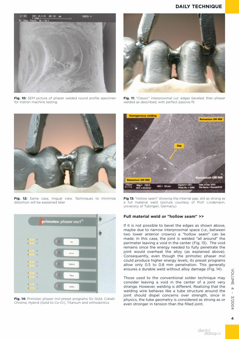
Fig. 11: "Classic" interproximal cut, edges beveled, then phaserwelded as described, with perfect passive fit
Fig 13: "Hollow seam" showing the internal gap, still as strong asa full material weld (picture courtesy of Prof. Lindemann,university of Tubingen, Germany)
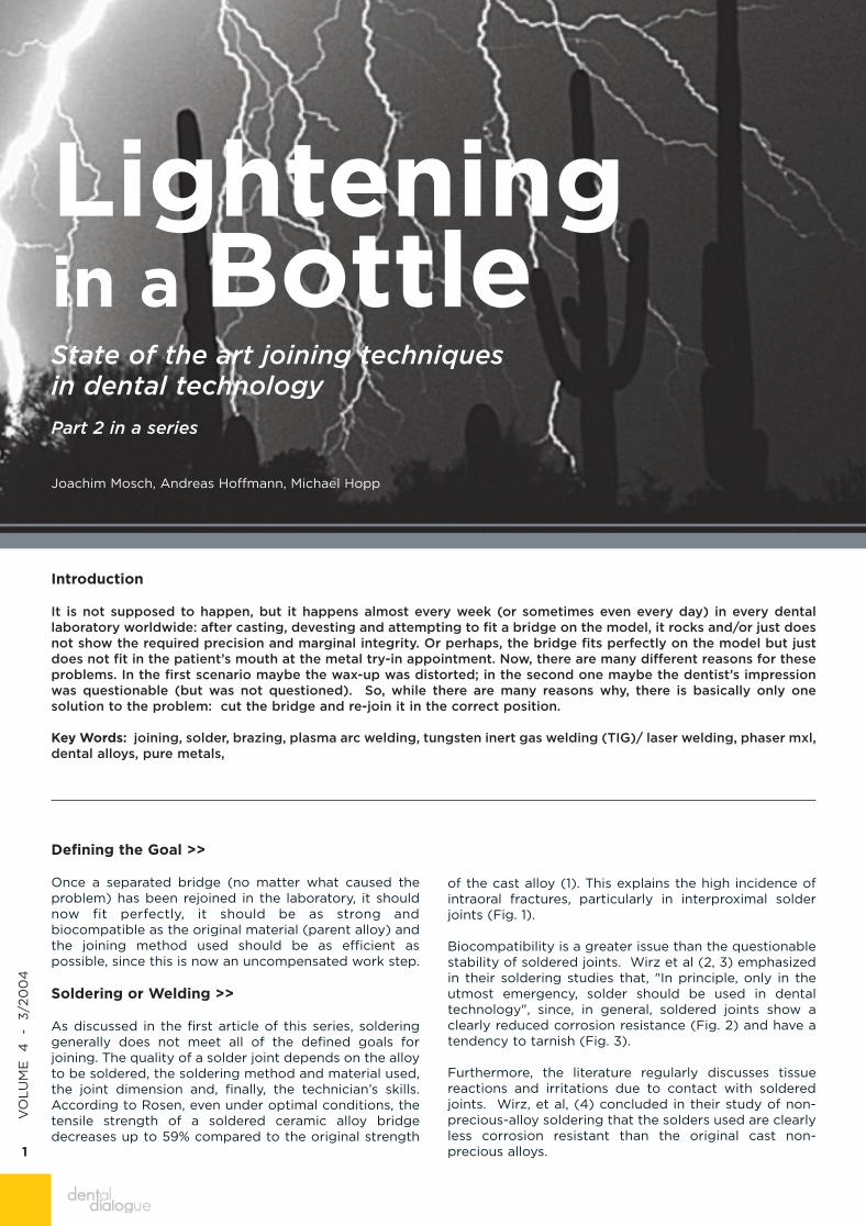
Fig. 10: SEM picture of phaser welded round profile specimenfor Instron machine testing
Fig. 12: Same case, lingual view. Techniques to minimizedistortion will be explained later
Fig. 14: Primotec phaser mxl preset programs for Gold, Cobalt-Chrome, Hybrid (Gold to Co-Cr), Titanium and orthodontics
Mosche 6/4/04 8:58 AM Page 4

DAILY TECHNIQUE
5
VO
LU
ME
4
-
3/2
00
4
Another concern that technicians may have with the"hollow seam" technique is that the void might degasduring porcelain firing, leading to bubbles in theporcelain. To prevent gassing, the individual spots shouldbe overlapped by at least 50%. However, even if thewelded seam is not gas tight (for example, if theoperator makes a mistake) there is no danger of gassingthrough the porcelain because as the opaque fires, thevacuum pump evacuates the chamber and the void rightaway. Then, as firing continues, the opaque sinters andcloses the opening in the welding seam. Besides, airnever causes bubbles ("frog-eyes") in the porcelain.They are caused by contamination of any kind thatgasses as it burns.
To summarize, when an interproximal cut needs welding,always bevel the edges when possible to create a fullmaterial weld from "inside out". If it is not possible tobevel, a "hollow seam" is made. If there is a large gap toweld with either technique, add welding wire of the sametype as the parent alloy to fill the gap.
Furthermore, when a long welding line must or can bemade, choose the hollow seam technique. In thefollowing case study the bridge was separateddiagonally through the pontic (Fig. 15 to Fig. 17).
Distortion: how to avoid it, how to use it >>
Welding performed with the laser or the primotecphaser mxl produces identical grain structures in thewelded areas (5). Both machines also yield similardistortion factors.
Usually, distortion is the "natural enemy" of thetechnician who has to weld a bridge, but sometimes itcan also be a friend. However, first we will discuss waysto defeat the "enemy" by understanding how "he" works.
Every material expands when it is heated and shrinks(contracts) when it cools. This becomes a problembecause shrinkage behavior is not linear (i.e., theexpansion is not necessarily identical to the contraction).When the energy hits the gap between two objects to bewelded, this energy melts the alloy and creates a meltingpool. This melting pool expands as long as the alloy isliquid and contracts when the alloy cools to the solid
stage. During cooling and contraction, the shrinkageforce pulls the two parts together as the melting poolnaturally cools toward the heat center. This wholeprocess happens within milliseconds but is enough todistort the object (Fig. 18).
To avoid this distortion, the shrinkage contraction needsto be guided. The most efficient way to do this is tofirmly secure the position of the objects to be joined. Ifthis is done properly, the melting pool shrinks downward"into" the object without distorting it (Fig. 19).
The power of this distorting force however must not beunderestimated. Just holding the two objects in place byhand (on the model) is not sufficient to direct theshrinkage contraction.
Now that the distortion mechanisms are understood, thequestion becomes which countermeasures to take. Thefirst and very reliable way to secure the objects intowelding position is to connect them with a stiff cast bar.These bars can be prefabricated for the alloys mostcommonly used in the lab. It only requires a sublingualbar wax pattern bent into a half circle. Once cast, the barcan be used many times, however, it might be necessaryto have a few bars with different widths (Fig. 20).
In addition to the bar, a piece of welding wire can beattached to bridge the gap, even though this extrasecurity (like wearing a belt with suspenders) is veryrarely needed (Fig. 21).
In those cases where it is not possible to place a stiff castbar to secure the two parts to be welded (for example aporcelain bridge without exposed metal), place thewelding spots in an alternating pattern. Weld one spotfrom the labial, the second from the lingual, etc. To insurethe proper fit, reseat the bridge after each weld. Since agap exists between the pieces (from the separating disk)always add additional welding wire from the beginningto fill the gap. Without additional wire, the coolingcontraction will pull the two parts together and distortthe case (compare Fig. 18).
The energy applied to the weld also affects distortion.The more energy (power x impulse duration time) used,the higher the distortion risk. With early laser experience,
Fig 15: Diagonal cut through the pontic. The wide gap requiresfilling with welding wire. The bent bar welded on top secures theposition and prevents distortion.
Fig. 16: Welding wire of the same alloy is used from thebeginning
Mosche 6/4/04 8:58 AM Page 5

6
DAILY TECHNIQUEV
OLU
ME
4 - 3
/20
04
many assumed that more energy would give betterresults. We now know this is wrong!!! Too much energyleads to alloy overheating and distortion. From thisexperience, when welding an unfamiliar alloy in thelaboratory, determine the power, time and spot diameterparameters by starting from a low energy level andincreasing the parameters accordingly rather thanbeginning with a high energy level.
Finally, the separation point impacts distortion. Asmentioned earlier, when the dentist cuts the bridgeinterproximally the lab has to live with it and perform thewelding as described. If the bridge rocks after devesting,due to an error in the production process, the techniciancontrols where to place the separating cut. It is better inthis case to cut through the crown (fig. 22 a,b,c).
A cut through the relatively thin crown (usually 0.3-0.5mm) reduces both the energy needed to melt it and thewelding wire diameter, therefore, decreasing the dangerof distortion (Fig 23 a - d). This cut is not possible whensoldering because the solder would flow inside thecrown, but becomes possible with welding since thealloy is molten only spot after spot.
Fig 18: The yellow area shows the dimension of the welding spotin the solid stage, the red areas (left and right) show theexpansion of the welding spot in the liquid stage.
Fig. 20: The cast bar is connected with one or two pulses toeach of the two parts to be joined. After welding, the bar can beeasily removed by hand.
Fig. 17: Since the welding line is long the hollow seam is themost productive way to rejoin the two parts.
Fig. 19: The two objects are tightly secured so the melting poolcannot shrink toward the center but is "forced" to shrinkdownwards
Fig. 21: Welding wire attached across the gap for security israrely needed.
Mosche 6/4/04 8:58 AM Page 6

DAILY TECHNIQUE
7
VO
LU
ME
4
-
3/2
00
4
Fig 23. a - d: A foolproof way to defeat distortion: a properly placed separating cut (through the crown), less welding energy, smallerdiameter welding wire and positioning with a stiff cast bar.
Fig 22 a,b,c: Soldering and welding are two different techniques! For soldering the cut would have to be interproximally. For weldingit is recommended to place the separating cut through the crown.
Mosche 6/4/04 8:58 AM Page 7

8
DAILY TECHNIQUEV
OLU
ME
4 - 3
/20
04
The distortion phenomenon has been reported in manyscientific publications worldwide. Himi (6), for example,proved laser welded three unit bridges fit (depending onthe fixation method) better than soldered and castbridges. This can be easily understood since accuratecasting and soldering depend heavily on technician skill.In welding, on the other hand, when prepared asdescribed above, the human factor plays only a minorrole.
Klinke et al. (7), interestingly enough, found thatsoldered ceramic alloy samples show less distortion thancast or laser welded control samples after the firstporcelain bake. This can be explained by tension in thealloy grain structure from the casting process. Duringsoldering, this tension is compensated automatically bythe evenly applied flame heat. The study suggested thatwhen a bridge framework fits poorly after casting, it canbe helpful to anneal the bridge in the porcelain furnace(800° C, one minute, no vacuum) to release the tensionand to then recheck the fit before separating.
Now we will look at how distortion can become a"friend". When a bridge rocks slightly after casting,
anneal first to determine whether tension relief in thegrain structure will make the bridge fit perfectly. If not,instead of separating, direct a few strong (notoverheating) welding pulses on the gingival or occlusalside of the connector (depending on the direction ofrocking). The distorting force can "bend" the bridge intothe right position. When applied properly, this techniquemay reduce the time spent separating and welding.
The "Lego block" principle >>
Welding can apply to other difficult procedures in thelaboratory. For example, when it is necessary to joindifferent alloys on one bridge (Fig 24). Instead of waxingup the two parts as usual in order to weld theminterproximally, wax the gold crown with an open roundkeyway on the mesial (Fig 25). Once the gold crown iscast, wax the ceramic portion with a distal post key thatfits into the open keyway on the gold crown. If theMetacon light cured wax system (primotec) is used, thefull cast crown and the ceramic bridge part can bewaxed at the same time. Once cast, the key inserts intothe open keyway like a Lego block. This connection isnow welded all around the outside of the joint using thealternating method (Fig. 26 a,b).
Fig 25: Full cast gold crown with the open keyway preparedmesially
Fig. 24: Full cast gold crown to be connected to non-preciousceramic bonding bridge
Fig 26 a,b: Depending on the space between the open keyway and key, additional welding wire may be needed to fill the gap andavoid distortion.
Mosche 6/4/04 8:58 AM Page 8

DAILY TECHNIQUE
9
VO
LU
ME
4
-
3/2
00
4
Literature:1. Rosen H: Ceramic/metal solder connectors; J Prosthod Dent 56, 671 - 676 (1986)2. Wirz J, Jaggi D, Schmidii F: Die Qualitat von Lotverbindungen - Teil 1:Lotverfahren, Prufmethoden und Zugfestigkeit; Quintessenz, 111-118 (1990)3. Wirz J, Jaggi D, Schmidii F: Die Qualitat von Lotverbindungen - Teil 2:Biegefestigkeit, Elastizitatsmodul und metallografische Gefuge; Quintessenz / 323 - 330 (1990)4. Wirz J, Schmidii F, Jager K: Korrisionsresistenz von Lotstellennichtedelmetallhaltiger Legierungen; Quintessenz Zahntech 17, 1140 - 1150 (1991)5. Lindemann, Prof. Dr. Wolfgang: Plasma versus Laser; dental-labor , 793 - 799 (2004)6. Himi A: Laser welding for precision bridge; Dentistry in Japan 37, 63 - 66 (2001)7. Klinke Th; Mack F, Nemitz Ch. Biffar: Der Verzug von verblendeten Prufkorpern nach Lotung und SchweiBung, ZWR 109, 613 - 618 (2000)
After making the initial welding spots, the bridge withcrown can be removed from the model (Fig 27).
Next, the key, which extends into the interior of thecrown, is welded from the inside (Fig. 28). Since thewelding spots melt and become concave, additionalinterior finishing is not necessary.
The "Lego block principle" results in a quick, very strongnon-precious joint. This general principle can be appliedto various other welding tasks. Once it becomes clearthat soldering and welding are different, a little ingenuitywill quickly lead to great success in dental welding eitherwith a laser or the primotec phaser mxl.
n
The next part of this welding series will address thefollowing subjects:
• Choosing wire materials (which wire for which alloytype)
• Alternate ways to separate and rejoin bridges
• Case study of improper fit in CAD/CAM milled Titaniumsuperstructure
• Case study of welding a cast bridge element to Captekor Galvano copings
• Welding porcelain veneered bridges
Fig 27: The key of the no precious bridge extends into theinterior of the crown.
Fig. 28: Since the welding spots are in general concave, it is notnecessary to refit the crown to the die after welding
Mosche 6/4/04 8:58 AM Page 9

10
DAILY TECHNIQUEV
OLU
ME
4 - 3
/20
04
Bio >> Joachim Mosch, CDT Joachim Mosch was born in 1959, studied dental engineering and technology as well as international business.Mr. Mosch has been working for 18 years (for the last 11 years as general manager) at the European headquartersof an American dental company before he started his own business (primotec /primodent) in the year 2000. Mr.Mosch has published various articles on different dental subjects such as Light Cured Wax (the Metacon System),functional bite splint therapy using light cured splint materials (primosplint), welding techniques and laser, a.s.o.and gives lectures on these subjects throughout the world. Mr. Mosch is married, has two children and lives withhis family in Bad Homburg/Germany.
Bio >> Andreas Hoffman, MDTAndreas Hoffmann, born in 1956 achieved his German Master Dental Technician degree in 1985. As of then hewas managing director and shareholder of a German dental laboratory group. He sold his shares and started hisnew laboratory 1. DSZ in the year 2000. At the same time he was appointed director of the "AkademieUmfassende Zahntechnik", a highly respected post graduate education program by one of the major Germanlaboratory associations (VUZ) where he is also member of the board of directors. He received the Straumannprize in 1998 and is known in Germany and Europe for his outstanding publications, lectures and courses onMetacon (light cured wax), phaser and laser welding techniques, Cercon, Versyo.com, Cerec, Procera, andGalvano. Mr. Hoffmann is married, has two children and lives with his family in Bilshausen/Germany.
Bio >> Dr. Michael HoppDr. Michael Hopp was born in 1962 in Binz, Isle of Rügen. He graduated from Humboldt School of Dentistry,University of Berlin in 1987 where he remained as the Assistant professor, Head of sector for PreclinicalProsthodontics. Since 1992 Dr. Hopp has worked for various groups in dentistry at the German Institute ofStandardization. He is a member of several Scientific Societies and is a guest lecturer at the DentalTechnician School in Berlin. Dr. Hopp is the Editor in chief of the Journal of International Dental Technology.He has given more than 300 lectures and has authored or co-authored more than 200 essays forinternational publications and book chapters.
Mosche 6/4/04 8:58 AM Page 10