mosfire requirements · web viewit will provide dramatic gains in solar system and galactic science...
TRANSCRIPT

Keck Adaptive Optics Note 456
NEXT GENERATION ADAPTIVE OPTICS: SYSTEM REQUIREMENTS DOCUMENT
Version 1.21April May 176, 2007
document.doc

CALIFORNIA ASSOCIATION FOR RESEARCH IN ASTRONOMY
NGAO System Requirements Document
document.doc

NGAO System Requirements Document
Table of Contents
1 Introduction .................................................................................................................................12 Scope and Applicability ..............................................................................................................13 References ...................................................................................................................................2
3.1 Related Documents .............................................................................................................23.2 Referenced Drawings ..........................................................................................................2
4 Revision History .........................................................................................................................25 Background .................................................................................................................................3
5.1 Purpose ...............................................................................................................................35.2 Motivation for the Development of NGAO ........................................................................35.3 Overview .............................................................................................................................4
6 Overall Requirements .................................................................................................................66.1 Science Requirements .........................................................................................................6
6.1.1 Purpose and Objectives ...............................................................................................66.1.2 Performance Requirements .........................................................................................66.1.3 Science Instrument Requirements ............................................................................116.1.4 Operations Requirements ..........................................................................................12
6.2 Observatory Overall Requirements ..................................................................................136.2.1 Purpose and Objectives .............................................................................................136.2.2 Facility Requirements ...............................................................................................136.2.3 Science Instrument Requirements ............................................................................156.2.4 Operational Requirements ........................................................................................166.2.5 Observatory Implementation Requirements .............................................................18
7 Optical Requirements ...............................................................................................................197.1 Purpose and Objectives .....................................................................................................19 Performance Requirements ...................................................................................................197.2 .................................................................................................................................................197.3 Implementation Requirements ..........................................................................................227.4 Design Requirements ........................................................................................................22
8 Mechanical Requirements ........................................................................................................298.1 Purpose and Objectives .....................................................................................................298.2 Performance Requirements ...............................................................................................298.3 Implementation Requirements ..........................................................................................298.4 Design Requirements ........................................................................................................30
9 Electronic/Electrical Requirements ..........................................................................................329.1 Purpose and Objectives .....................................................................................................329.2 Performance Requirements ...............................................................................................329.3 Implementation Requirements ..........................................................................................329.4 Design Requirements ........................................................................................................32
10 Safety Requirements .............................................................................................................3310.1 Purpose and Objectives .....................................................................................................3310.2 Scope .................................................................................................................................3310.3 Laser Safety Requirements ...............................................................................................33
document.doc

NGAO System Requirements Document
Table of Contents
10.4 Laser Projection Safety Requirements ..............................................................................3310.4.1 Aircraft Safety ..........................................................................................................3310.4.2 Space Command .......................................................................................................33
11 Software Requirements .........................................................................................................3411.1 Purpose and Objectives .....................................................................................................3411.2 Scope .................................................................................................................................3411.3 Performance Requirements ...............................................................................................3411.4 Implementation Requirements ..........................................................................................3411.5 Design Requirements ........................................................................................................34
12 Interface Requirements .........................................................................................................3512.1 Purpose and Objectives .....................................................................................................3512.2 Performance Requirements ...............................................................................................3512.3 Implementation Requirements ..........................................................................................3512.4 Design Requirements ........................................................................................................35
12.4.1 Optical Interface .......................................................................................................3512.4.2 Mechanical Interface ................................................................................................3512.4.3 Electrical/Electronic Interface ..................................................................................3512.4.4 Software Interface .....................................................................................................36
13 Reliability Requirements ......................................................................................................3713.1 Purpose .............................................................................................................................3713.2 Scope .................................................................................................................................3713.3 Performance ......................................................................................................................37
14 Spares Requirements ............................................................................................................3715 Service and Maintenance Requirements ...............................................................................3716 Documentation Requirements ..............................................................................................38
16.1 Documentation Package ...................................................................................................3816.2 Drawings ...........................................................................................................................3816.3 Electrical/Electronic Documentation ................................................................................3816.4 Software ............................................................................................................................38
17 Glossary ................................................................................................................................391 Introduction .................................................................................................................................12 Scope and Applicability ..............................................................................................................13 References ...................................................................................................................................2
3.1 Related Documents .............................................................................................................23.2 Referenced Drawings ..........................................................................................................2
4 Revision History .........................................................................................................................25 Background .................................................................................................................................3
5.1 Purpose ...............................................................................................................................35.2 Motivation for the Development of NGAO ........................................................................35.3 Overview .............................................................................................................................3
6 Overall Requirements .................................................................................................................66.1 Science Requirements .........................................................................................................6
document.doc

NGAO System Requirements Document
Table of Contents
6.1.1 Purpose and Objectives ...............................................................................................66.1.2 Performance Requirements .........................................................................................66.1.3 Science Instrument Requirements ..............................................................................8
6.2 Observatory Overall Requirements ..................................................................................106.2.1 Purpose and Objectives .............................................................................................106.2.2 Facility Requirements ...............................................................................................106.2.3 Science Instrument Requirements ............................................................................116.2.4 Operational Requirements ........................................................................................126.2.5 Observatory Implementation Requirements .............................................................13
7 Optical Requirements ...............................................................................................................147.1 Purpose and Objectives .....................................................................................................147.2 Performance Requirements ...............................................................................................147.3 Implementation Requirements ..........................................................................................157.4 Design Requirements ........................................................................................................15
8 Mechanical Requirements ........................................................................................................198.1 Purpose and Objectives .....................................................................................................198.2 Performance Requirements ...............................................................................................198.3 Implementation Requirements ..........................................................................................198.4 Design Requirements ........................................................................................................19
9 Electronic/Electrical Requirements ..........................................................................................219.1 Purpose and Objectives .....................................................................................................219.2 Performance Requirements ...............................................................................................219.3 Implementation Requirements ..........................................................................................219.4 Design Requirements ........................................................................................................21
10 Safety Requirements .............................................................................................................2210.1 Purpose and Objectives .....................................................................................................2210.2 Scope .................................................................................................................................2210.3 Laser Safety Requirements ...............................................................................................2210.4 Laser Projection Safety Requirements ..............................................................................22
10.4.1 Aircraft Safety ..........................................................................................................2210.4.2 Space Command .......................................................................................................22
11 Software Requirements .........................................................................................................2311.1 Purpose and Objectives .....................................................................................................2311.2 Scope .................................................................................................................................2311.3 Performance Requirements ...............................................................................................2311.4 Implementation Requirements ..........................................................................................2311.5 Design Requirements ........................................................................................................23
12 Interface Requirements .........................................................................................................2412.1 Purpose and Objectives .....................................................................................................2412.2 Performance Requirements ...............................................................................................2412.3 Implementation Requirements ..........................................................................................2412.4 Design Requirements ........................................................................................................24
document.doc

NGAO System Requirements Document
Table of Contents
12.4.1 Optical Interface .......................................................................................................2412.4.2 Mechanical Interface ................................................................................................2412.4.3 Electrical/Electronic Interface ..................................................................................2412.4.4 Software Interface .....................................................................................................25
13 Reliability Requirements ......................................................................................................2613.1 Purpose .............................................................................................................................2613.2 Scope .................................................................................................................................2613.3 Performance ......................................................................................................................26
14 Spares Requirements ............................................................................................................2615 Service and Maintenance Requirements ...............................................................................2616 Documentation Requirements ..............................................................................................27
16.1 Documentation Package ...................................................................................................2716.2 Drawings ...........................................................................................................................2716.3 Electrical/Electronic Documentation ................................................................................2716.4 Software ............................................................................................................................27
17 Glossary ................................................................................................................................28
document.doc

NGAO System Requirements Document
Figures and Tables
Figure 1 Keck telescope structure.......................................................................................................5
Table 1 NGAO baseline Mauna Kea Cn2 Profile................................................................................8
Table 2 Glossary of Terms...............................................................................................................28
document.doc

NGAO System Requirements Document
1 INTRODUCTION
This document describes the requirements for the Next Generation Adaptive Optics (NGAO) system to be built for the W. M. Keck Observatory (WMKO).
The requirements in this document are intended to be at a level appropriate for the system design phase. Further development of the requirements will take place in the next phase of the project (preliminary design). In particular, parametric performance requirements given at this stage are intended to indicate the scope and format of the requirements, but do not in all cases establish final values for the specified parameters. In some cases values for these parameters have yet to be established and are given as TBD.
A more generic set of requirements for new WMKO instrumentation is described in the Observatory’s “Instrumentation Baseline Requirements Document.” These requirements are also applicable to NGAO. The NGAO System Requirements Document will take precedence over the “Instrumentation Baseline Requirements Document” in the event of a conflict.
It is important to understand that at this stage of development the requirements provide a basis for identifying the parameters that will be part of the system’s specifications, but the values given are subject to change as the development continues. During the next phases of the project work will be done to refine the requirements for review at the preliminary design review. The final requirements to be reviewed at the detailed design review will form the basis for the acceptance test criteria for the instrument. The purpose of this document is to define and communicate the requirements for the NGAO-specific design and implementation in terms of the needed scientific and technical performance. The document also expresses specific requirements for implementation or design where those requirements are essential to satisfactory integration and interoperation of NGAO with the observatory systems. The document avoids prescribing specific design or implementation solutions except for solutions that embody the Observatory’s unique knowledge or experience. The document establishes requirements for the NGAO that will guide the design through the detailed design phase.
2 SCOPE AND APPLICABILITY
This document establishes requirements for all aspects of NGAO beyond those already specified in the “Instrumentation Baseline Requirements Document”. This document also establishes requirements for changes to related Keck telescope subsystems and software where required.
This document does not address the requirements for the science instruments that will work with NGAO, although it does cover the NGAO interfaces to these instruments. Separate system requirements documents will need to be prepared for each of these instruments as part of their design process.
-1-document.doc

NGAO System Requirements Document
3 REFERENCES
3.1 Related Documents
1. Instrumentation Baseline Requirements Document.2. KAON 153. Coordination and Use of Laser Beacons for AO on Mauna Kea.3. KAON 455. Science Case Requirements Document.4. KAON 399. NGAO Proposal Executive Summary.5. KAON 400. NGAO Proposal.6. KAON 428. Implications and requirements for Interferometry with NGAO.7. KAON 455. NGAO Science Case Requirements Document v1.0.8. ANSI Z136.1 Safe Use of Lasers Indoors (2000).9. ANSI Z136.6 Safe Use of Lasers Outdoors (2000).
3.2 Referenced Drawings
Table X lists the drawing numbers, revisions and date, source and title for all drawings referenced in this document.
4 REVISION HISTORY
Version Date Author Reason for revision / remarks0.1 Jan. 16, 2007 Wizinowich Initial version0.3 Feb. 1, 2007 Wizinowich Multiple edits0.4 Feb. 6, 2007 Wizinowich Multiple edits. Included seeing & telescope
environment in section 6.1.21.0 Feb. 21, 2007 Wizinowich Added Dekany performance requirements
input1.1 Apr. 17, 2007 Wizinowich Edited section 61.2 May 15, 2007 Wizinowich Incorporated input from NGAO team
meeting 6
-2-document.doc

NGAO System Requirements Document
5 BACKGROUND
5.1 Purpose
The purpose of the background section of this document is to provide context and related information for the requirements defined in later sections of this document.
5.2 Motivation for the Development of NGAO
The Keck telescopes are the world’s largest optical and infrared telescopes. Because of their large apertures the Keck telescopes offer the highest potential sensitivity and angular resolution currently available. WMKO has already demonstrated scientific leadership in high angular resolution astronomy with the first NGS and LGS AO systems on 8-10 m telescopes. The importance of achieving the full potential of the Keck telescopes is recognized in the Observatory’s strategic plan which identifies leadership in high angular resolution astronomy as a key long-term goal.
In order to maintain our leadership in this field we must pursue new AO systems and the instrumentation to exploit them. We have examined, and are continuing to examine, a broad range of key science goals in order to identify the most compelling future science goals of our community and to determine what is needed to realize these goals. As a result we have identified that NGAO should provide the following suite of capabilities:
Near diffraction-limited performance at near infrared wavelengths, producing a point spread function with unprecedented precision, stability and contrast;
Increased sky coverage and a multiplexing capability, enabling a much broader range of science programs; and
AO correction in the red portion of the visible spectrum (0.6-1.0 µm), delivering the highest angular resolution images available for filled aperture telescopes.
NGAO will be a broad and powerful facility with the potential to achieve major advances in astrophysics. It will provide dramatic gains in solar system and galactic science where AO has already demonstrated a strong scientific impact. NGAO will also allow for extraordinary advances in extragalactic astronomy, far beyond the initial gains being made with the Observatory’s current AO systems.
To be clear NGAO need not be a single facility. It may be that the requirements are best met with multiple AO systems.
The NGAO proposal (KAON 400) and NGAO proposal executive summary (KAON 399) provide more background on the motivation for the development of NGAO. Further scientific motivation is provided in the NGAO science case requirements document (KAON 455).
-3-document.doc

NGAO System Requirements Document
5.3 Overview
The scientific and technical requirements for NGAO result in the following basic systems:
1. AO system. The AO system will likely consist of an AO enclosure, an opto-mechanical system, and software and electronics for both non real-time and real-time control.
2. Laser facility. The laser facility will likely consist of a laser enclosure, the laser(s), the launch facility including a beam transport system and launch telescope, safety systems and laser system control electronics and software.
3. Science operations facility. The science operations facility will primarily include the software and computers required to support operation of the AO system and science instruments. This includes operating the systems for nighttime observing as well as pre- and post-observing activities.
4. Science instruments. The three highest priority instruments are currently a near-IR imager, a visible imager and a deployable near-IR integral field unit (IFU). Three lower priority instruments have also been identified including a near-IR IFU, a visible IFU and an L and M-band imager. There is also a requirement that the NGAO project be designed so as to allow the continued AO support of the Interferometer and the fiber injection module used for the ‘OHANA (Optical Hawaiian Array for Nanoradian Astronomy) project.
The AO and laser facilities and the science instruments will have to interface with the telescope structure. Figure 1 shows a schematic view of a Keck telescope. The most likely location for the NGAO system and science instruments is on one of the Nasmyth platforms of the telescope. Nominally we have chosen the left Nasmyth platform of the Keck II telescope as our starting point. The most likely location for the projection telescope is behind the f/15 secondary mirror in the top end of the telescope.
-4-document.doc

NGAO System Requirements Document
Figure 1 Keck telescope structure
-5-document.doc

NGAO System Requirements Document
6 OVERALL REQUIREMENTS
6.1 Science Requirements
6.1.1 Purpose and Objectives
The purpose of the science overall requirements section is to summarize and convey requirements that apply generally to the overall NGAO system and its accessories. These are based on the Science Case Requirements Document (SCRD) (KAON 455) and, in this initial release, also on the NGAO proposal (KAON 399).
6.1.2 Performance Requirements
The performance requirements developed in the SCRD are summarized in the following table. These will be updated as the science case requirements and performance budgets become better defined.
# Performance Requirement
Discussion Based on
1 Telescope plus NGAO transmission to the input of the science instruments ≥ 70% at 0.7-2.4 µm.
The wavelength range is explicitly identified in the SCRD. The transmission is a placeholder. Need to determine if we should extend this down to H (656.3 nm). May be better to write in terms of SNR.
KAON 455 (v1) Table 4
2 Goal: Telescope plus NGAO transmission to the input of the science instruments ≥ 70% at L-band.
KAON 455 (v1) Table 4 low mass stars & Galactic Center science cases
3 NGAO background, including the science instrument shall be ≤ 100% of the sky plus telescope at K-band.
The measured NIRC2 K-band background is 12.24 mag/arcsec2 . The predicted sky background is 13.46.
KAON 455 (v1) Table 4: for the asteroid science cases the background should be ≤ the current LGS background
4 Goal: NGAO background including the science instruments shall be ≤ 20% of the sky plus telescope at K-band.
KAON 455 (v1) Table 4: High z galaxies.
5 Wavefront error ≤ 140 nm rms for V ≤ 17 on-axis guide star
KAON 455 (v1) Table 4: asteroid shape & companions.
-6-document.doc

NGAO System Requirements Document
6 Wavefront error ≤ 140 nm rms for V ≤ 16 guide star ≤ 30” from science object
KAON 455 (v1) Table 4: planets around low mass stars.
7 Wavefront error ≤ 170 nm rms for objects ≤ 5” from the Galactic Center
KAON 455 (v1) Table 4: Galactic Center.
8 Encircled energy ≥ 50% within a 0.05” diameter circle at K-band for sky coverage ≥ 5%
KAON 455 (v1) Table 4: High z galaxies.
9 Encircled energy ≥ 50% within a 0.075” diameter circle at K-band for sky coverage ≥ 30%
KAON 455 (v1) Table 4: High z galaxies.
10 The companion sensitivity shall be ΔH ≥ 5.5 mag at 0.5” separation for a V ≤ 17 on-axis guide star
KAON 455 (v1) Table 4: asteroid companions.
11 The companion sensitivity shall be ΔH ≥ 13 at 1” separation for a V ≤ 16 guide star ≤ 30” from science object
KAON 455 (v1) Table 4: planets around low mass stars.
12 Sensitivity? Does this just drive transmission?
KAON 455 (v1) Table 4: planets around low mass stars.
13 H-band photometric accuracy of ≤ 0.05 mag at 0.6” for ΔH = 3 for a V ≤ 17 on-axis guide star
KAON 455 (v1) Table 4: asteroid companions.
14 H-band photometric accuracy of ≤ 0.05 mag relative to the primary star at 1” separation for ΔH = 13 for a V ≤ 16 guide star ≤ 30” from science object
KAON 455 (v1) Table 4: planets around low mass stars.
15 “Uncalibrated detector distortion < 1.5 mas”
Is this really the way we want to write this? Shouldn’t we put the high level requirement here?
KAON 455 (v1) Table 4: asteroid companions.
16 “1/10 of the PSF FWHM” Wouldn’t be better off writing this as mas?
KAON 455 (v1) Table 4: planets around low mass stars.
17 Astrometric accuracy ≤ 100 µas at K-band for
KAON 455 (v1) Table 4: Galactic Center.
-7-document.doc

NGAO System Requirements Document
objects ≤ 5” from the Galactic Center
18 Radial velocity accuracy ≤ 10 km/sec at K-band for objects ≤ 5” from the Galactic Center
KAON 455 (v1) Table 4: Galactic Center.
19 Overheads between targets ≤ 10 min
KAON 455 (v1) Table 4: Asteroid size & companions, planets around low mass stars.
20 Strehl or PSF stability requirement?
TBD
21 Unvignetted contiguous fields shall be provided to the NIR and visible science imagers and single field IFUs. These fields should be centered to within 1” of the telescope’s optical axis. The maximum field size is 20”x20”.
Driven by the science requirements on the contiguous field science instruments.
22 Multiple unvignetted contiguous fields shall be provided to the NIR d-IFU. Each field should be ≥ 4” in diameter.
Driven by science requirements on the NIR d-IFU.
23 The unvignetted field of regard provided to the NIR d-IFU shall have a total area of ≥ 6 arcmin2
and shall have a maximum off-axis distance of ≤ 1.5’ with respect to the telescope’s optical axis.
Driven by science requirements on the NIR d-IFU.
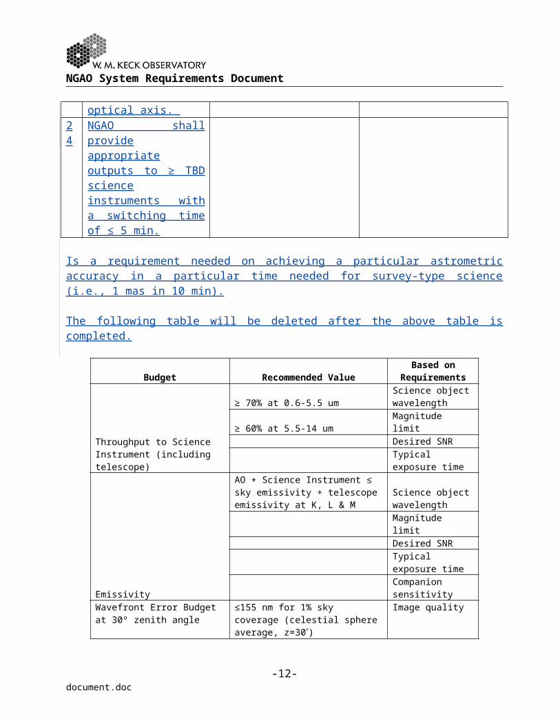
24 NGAO shall provide appropriate outputs to ≥ TBD science instruments with a switching time of ≤ 5 min.
Is a requirement needed on achieving a particular astrometric accuracy in a particular time needed for survey-type science (i.e., 1 mas in 10 min).
-8-document.doc

NGAO System Requirements Document
The following table will be deleted after the above table is completed.
Budget Recommended ValueBased on
Requirements
Throughput to Science Instrument (including telescope)
≥ 70% at 0.6-5.5 umScience object wavelength
≥ 60% at 5.5-14 um Magnitude limitDesired SNRTypical exposure time
Emissivity
AO + Science Instrument ≤ sky emissivity + telescope emissivity at K, L & M
Science object wavelengthMagnitude limitDesired SNRTypical exposure timeCompanion sensitivity
Wavefront Error Budget at 30º zenith angle (including science instrument
≤155 nm for 1% sky coverage (celestial sphere average, z=30) Image quality≤205 nm for 20% sky coverage Sky coverage≤240 nm for 80% sky coverage
Photometric accuracy
≤0.01 mag at 0.7-2.5 um for ≤ 5" from H ≤ 16 NGS≤0.02 mag at 0.7-3.5 um for ≤ 10" from H<16 NGS≤0.05 mag at 0.9-2.5 um for ≤ 20" off-axis & 20% sky coverage≤0.1 mag at 0.7-2.5 um for ≤ 20" off-axis & 20% sky coverage
Astrometric accuracy
≤0.1 mas for Galactic Center≤10 mas for 0.7-3.5 um & 30% sky coverage ≤50 mas for 0.7-3.5 um & 50% sky coverage
Polarimetry accuracy ≤0.5%
Companion Sensitivity
≥4 magnitudes at 0.055" at 1-2.5 um for Galactic Center≥10 mags at 0.5" at 0.7-3.5 um for 30% sky coverage & ≤ 20" object diameter
Observing Efficiency
≤20 min overhead per night Facility-class≤120 sec between end of slew & ready for science exposure ≤10 sec between start of nod command & ready for science exposure
-9-document.doc

NGAO System Requirements Document
≤120 sec to switch between LGS & NGS mode≤600 sec to switch between NGS & LGS mode (assuming daytime setup)≤120 sec to switch between science instruments (assuming daytime setup)
Up-time ≤5% of time lost to problems Facility-class
The atmosphere and telescope parameters assumed for achieving these numbers are summarized below.
Atmospheric Seeing:
The NGAO system shall provide its nominal performance when the atmospheric seeing is characterized by the following conditions. An evaluation of existing seeing data has been performed (KAON 303). The KAON 303 profile was modified to include a stronger ground layer and the standard r0 value was lowered from 20 to 18 cm. The resultant baseline median Cn
2 profile is presented in Table 1. From this model we calculate the following turbulence parameters for 0.5 µm wavelength (note that r0, θ0 and 1/fG increase as λ6/5):
Fried’s seeing parameter r0 = 18 cm Isoplanatic angle θ0 = 2.5 arcsec Turbulence characteristic frequency fG = 39 Hz
In addition, we have adopted a standard deviation for r0 of r0 = 3 cm with a characteristic evolution time of t = 3 min.
Table 1 NGAO baseline Mauna Kea Cn2 Profile
Altitude (km) Fractional C Wind Speed (m/s)0.0 0.471 6.72.1 0.184 13.94.1 0.107 20.86.5 0.085 29.09.0 0.038 29.012.0 0.093 29.014.8 0.023 29.0
Telescope and Dome Environment:
The NGAO system shall provide its nominal performance when the telescope and dome environment can be characterized by the following conditions.
-10-document.doc

NGAO System Requirements Document
Dome & telescope seeing: The Keck dome and telescope environment degrades the intrinsic seeing by less than 0.1 arcsec, in quadrature, as measured from the effective increase in image FWHM (this change corresponds to decreasing the r0 parameter from 18 cm to 17.8 cm).
Phasing: The phasing errors will be 10 nm rms wavefront or less before NGAO correction. Standard performance is 60 nm rms currently. Currently available algorithms have demonstrated 10 nm rms. This error interacts with the segment figure error discussed next. We may want to place an error on the overall telescope wavefront figure PSD instead.
Segment figure: The wavefront error of the 36 segments will be less than 80 nm rms wavefront after warping, but before NGAO correction; this number is an average over all 36 segments segment. As a goal the wavefront error shall be 80 nm rms over each segment.
Stacking: The segment stacking errors will contribute less than 20 nm rms wavefront to the overall wavefront error before NGAO correction.
Line of sight jitter: The aggregate line of sight jitter (wavefront tip and tilt) resulting from motion of the primary, secondary and tertiary mirrors will be less than 0.020 arc seconds rms before correction by the NGAO. This vibration is known to currently be largely dominated by a narrow resonance at ~29 Hz.
Segment motion: The motion of each segment as a solid body will be less than 0.015 arc seconds rms before correction by the NGAO. This vibration is known to currently be largely in a narrow resonance at ~29 Hz.
6.1.3 Science Instrument Requirements
The NGAO system must be capable of supporting the following science instruments (in rough order of priority), based on the NGAO proposal and SCRD:
Visible imager. Wavelength range = 0.6 to 1.1 µm. Field of view = 20”x20”. Image sampling = 6 mas pixels.
Near-IR imager. Wavelength range = 1.0 to 2.45 µm. Field of view = 20”x20”. Image sampling = 10 mas.
Deployable near-IR Integral Field Unit (IFU). Wavelength range = 1.0 to 2.45 µm. Field of Regard = 1.5’x1.5’ with 3x3.4” fields of view for each IFU. Image sampling = 100 mas.
Near-IR IFU. Wavelength range = 1.0 to 2.45 µm. Field of view from 2”x1.25” to 16”x5”. Image sampling = 20 to 100 mas.
Visible IFU. Wavelength range = 0.6 to 1.1 µm. Field of view from 1.2”x1.36” to 12”x6.8”. Image sampling = 20 to 100 mas.
L and M-band imager. Wavelength range = 3.0 to 5.3 µm. Field of view = 25”x25”. Image sampling = 25 mas.
Future science instruments from the above list or completely new instruments. These future science instruments would need to be designed so as to fit at a movable port or to replace a fixed first generation instrument.
-11-document.doc

NGAO System Requirements Document
It is TBD whether the NGAO system will need to support any of the existing science instruments (NIRC2, NIRSPEC or OSIRIS). The Interferometer and ‘OHANA requirements are discussed in section 6.2.3.
It is a goal for NGAO to support visitor science instruments.
6.1.4 Operations Requirements
The top-level science operations goals for the NGAO system including the science instruments are the following:
1. Science-grade quality of the raw data (i.e., image quality and completeness of observations).
2. Science-grade quality of the data products (i.e., photometry, astrometry, etc.).3. Science impact from a given data product (i.e., number of publications and citations).
Some level of data reduction pipeline may be necessary in order to support goal 2.
Does a distortion solution for astrometry need to be added as an operations requirement?
-12-document.doc

NGAO System Requirements Document
6.2 Observatory Overall Requirements
6.2.1 Purpose and Objectives
The purpose of the overall requirements section is to convey requirements that apply generally to the overall instrument and its accessories based on the Observatory’s requirements.
Note that the Observatory’s standard requirements for all new instrumentation are summarized in the Instrumentation Baseline Requirements Document. Additional Observatory requirements specific to NGAO are listed in the following sections.
6.2.2 Facility Requirements
The following are requirements imposed by the nature of the existing facility.
# Performance Requirement
Discussion Based on
1 The NGAO system & science instruments should be located on the Nasmyth platform of one of the Keck telescopes
The Keck telescope foci and Nasmyth deck storage locations are already heavily utilized. The current AO systems occupy the left Nasmyth platform locations of both telescopes. HIRES occupies the right Nasmyth on Keck I while DEIMOS and NIRSPEC share the right Nasmyth on Keck II. The Cassegrain foci are occupied by LRIS (and MOSFIRE in the future) on Keck I and by ESI on Keck II. The bent Cassegrain ports are believed to have inadequate space and weight capacities. The prime focus could potentially be available but there would be many constraints on an instrument at this location. The most viable option is in the location of an existing AO system. Alternatives would be to decommission HIRES or for the existing AO system and the
-13-document.doc
NGAO System Requirements Document
NGAO system to be able to share the same platform.
2 The NGAO system should accommodate the entire Keck pupil
The Keck primary has a maximum edge-to-edge diameter of 10.949 m.
3 If the existing f/15 or f/40 secondary mirrors are used then the NGAO system will be constrained by the resultant f/#, focal plane and pupil location
Both telescopes have f/15 secondary mirrors, as well as chopping secondary units that can accommodate f/25 and f/40 secondary mirrors. The choice of f/15 secondary mirrors for the current AO systems was largely driven by the resultant reduced size of the AO systems and the availability of PCS (Phasing Camera System) via a rotation of the tertiary mirror. The inability of the current systems to chop at the telescope pupil has been a limitation for thermal IR observations.The focal length of the telescope with the f/15 secondary mirror is 150 m. The 10.949 m primary corresponds to an f/13.66 beam with an exit pupil diameter of 1.460 m located 19.948 m in front of the focal plane.
4 The NGAO facility must not compromise the performance of a non-NGAO instrument when that instrument is being used for science or engineering
This requirement is intended to ensure that the NGAO facility, when not in use, does not introduce vibrations or stray light that might impact the performance of another science instrument or an engineering instrument such as PCS.
5 The NGAO facility must not compromise the performance of the telescope when the telescope is used for non-NGAO observations.
The NGAO system should not impact the dynamic performance of the telescope through vibrations or different telescope dynamics.
-14-document.doc

NGAO System Requirements Document
If NGAO hardware is to be mounted in the top-end then it must be designed/implemented not to compromise the secondary mirror performance.
6 The NGAO facility / science instrument combination should provide compensation for science field rotation
The Alt-Az telescope design requires compensation for field rotation in order to keep the science field fixed on the science instrument.
7 The NGAO facility / science instrument combination should provide compensation for pupil rotation
The Alt-Az telescope design and the irregular shape of the Keck primary mirror require that NGAO system provide appropriate compensation for pupil rotation. Examples: The existing Keck AO system updates the reconstructor to compensate for pupil orientation. The NIRC2 coronagraph mask rotates to match the rotating pupil.
8 The NGAO facility should provide compensation for LGS projector rotation
The Alt-Az telescope design will cause the laser projector (and the resultant LGS asterism) to rotate with respect to the Nasmyth platform. Compensation will be required to maintain the off-axis LGS on the corresponding wavefront sensor.
# Observatory Facility Requirements
Discussion
1 The NGAO system & science instruments should be located on the Nasmyth platform of one of the Keck telescopes
The Keck telescope foci and Nasmyth deck storage locations are already heavily utilized. The current AO systems occupy the left Nasmyth platform locations of both telescopes. HIRES occupies the right Nasmyth on Keck I while DEIMOS and NIRSPEC share the right Nasmyth on Keck II. The Cassegrain foci are occupied by LRIS (and MOSFIRE in the future) on Keck I and by ESI on Keck II. The bent Cassegrain ports are believed to have inadequate space and weight capacities. The prime focus could potentially be available but there would be many constraints on an instrument at this location. The most viable option is in the
-15-document.doc

NGAO System Requirements Document
location of an existing AO system. Alternatives would be to decommission HIRES or for the existing AO system and the NGAO system to be able to share the same platform.
2 The NGAO system should accommodate the entire Keck pupil
The Keck primary has a maximum edge-to-edge diameter of 10.949 m.
3 If the existing f/15 or f/40 secondary mirrors are used then the NGAO system will be constrained by the resultant f/#, focal plane and pupil location
Both telescopes have f/15 secondary mirrors, as well as chopping secondary units that can accommodate f/25 and f/40 secondary mirrors. The choice of f/15 secondary mirrors for the current AO systems was largely driven by the resultant reduced size of the AO systems and the availability of PCS (Phasing Camera System) via a rotation of the tertiary mirror. The inability of the current systems to chop at the telescope pupil has been a limitation for thermal IR observations.The focal length of the telescope with the f/15 secondary mirror is 150 m. The 10.949 m primary corresponds to an f/13.66 beam with an exit pupil diameter of 1.460 m located 19.948 m in front of the focal plane.
4 The NGAO facility must not compromise the performance of a non-NGAO instrument when that instrument is being used for science or engineering
This requirement is intended to ensure that the NGAO facility, when not in use, does not introduce vibrations or stray light that might impact the performance of another science instrument or an engineering instrument such as PCS.
5 The NGAO facility must not compromise the performance of the telescope when the telescope is used for non-NGAO observations.
The NGAO system should not impact the dynamic performance of the telescope through vibrations or different telescope dynamics.
If NGAO hardware is to be mounted in the top-end then it must be designed/implemented not to compromise the secondary mirror performance.
6 The NGAO facility / science instrument combination should provide compensation for science field rotation
The Alt-Az telescope design requires compensation for field rotation in order to keep the science field fixed on the science instrument.
7 The NGAO facility / science instrument combination should provide compensation for pupil rotation
The Alt-Az telescope design and the irregular shape of the Keck primary mirror require that NGAO system provide appropriate compensation for pupil rotation. Examples: The existing Keck AO system updates the reconstructor to compensate for pupil orientation. The NIRC2 coronagraph mask rotates to match the rotating pupil.
-16-document.doc

NGAO System Requirements Document
8 The NGAO facility should provide compensation for LGS projector rotation
The Alt-Az telescope design will cause the laser projector (and the resultant LGS asterism) to rotate with respect to the Nasmyth platform. Compensation will be required to maintain the off-axis LGS on the corresponding wavefront sensor.
6.2.3 Science Instrument Requirements
In addition to the science instrument requirements specified in section 6.1.3 the NGAO facility must allow the Observatory to continue supporting Interferometer science with the two Keck telescopes. The requirements for these instruments are developed in KAON 428 and are further specified in later sections.
# Observtory Instrument Requirement
Discussion Based on
1 The NGAO facility should support the Keck Interferometer (KI) with performance as good or better than provided by the pre-NGAO Keck AO systems
The KI dual star modules (DSM) currently move into both AO enclosures on rails to feed the KI. The requirement to feed the KI requires that collimated light can be fed to the DSM and that the field rotation, pupil rotation, longitudinal dispersion and polarization from the NGAO system and the AO system on the other telescope be identical. See KAON 428 Implications and Requirements for Interferometry with NGAO.
2 The NGAO system should support the ‘OHANA interferometer with performance as good or better than provided by the pre-NGAO Keck AO systems
Injection modules are currently placed on each AO bench to feed an optical fiber that goes to the KI. In future the output from these fibers will be interfered with those from multiple telescopes.
# Observatory Instrument
Requirements
Discussion
1 The NGAO facility should support the Keck Interferometer (KI) with performance
The KI dual star modules (DSM) currently move into both AO enclosures on rails to feed the KI. The requirement to feed the KI requires that collimated light can be fed to the DSM and that the field rotation, pupil rotation, longitudinal dispersion and
-17-document.doc
NGAO System Requirements Document
as good or better than provided by the pre-NGAO Keck AO systems
polarization from the NGAO system and the AO system on the other telescope be identical. See KAON 428 Implications and Requirements for Interferometry with NGAO.
2 The NGAO system should support the ‘OHANA interferometer with performance as good or better than provided by the pre-NGAO Keck AO systems
Injection modules are currently placed on each AO bench to feed an optical fiber that goes to the KI. In future the output from these fibers will be interfered with those from multiple telescopes.
6.2.4 Operational Requirements
The purpose of this section is to document the Observatory’s overall requirements for the support of science operations.
# Observtory Operational Requirement
Discussion Based on
1 The NGAO system must be facility-class
Facility-class has many implications on safety, operability, reliability, maintainability, lifetime, documentation, configuration management, etc.
2 The NGAO system must complete an operations transition review where operational responsibility is transferred from development to operations
This has implications on defining transition requirements and on training.
3 The NGAO system must be capable of supporting 275 nights/year of science operation
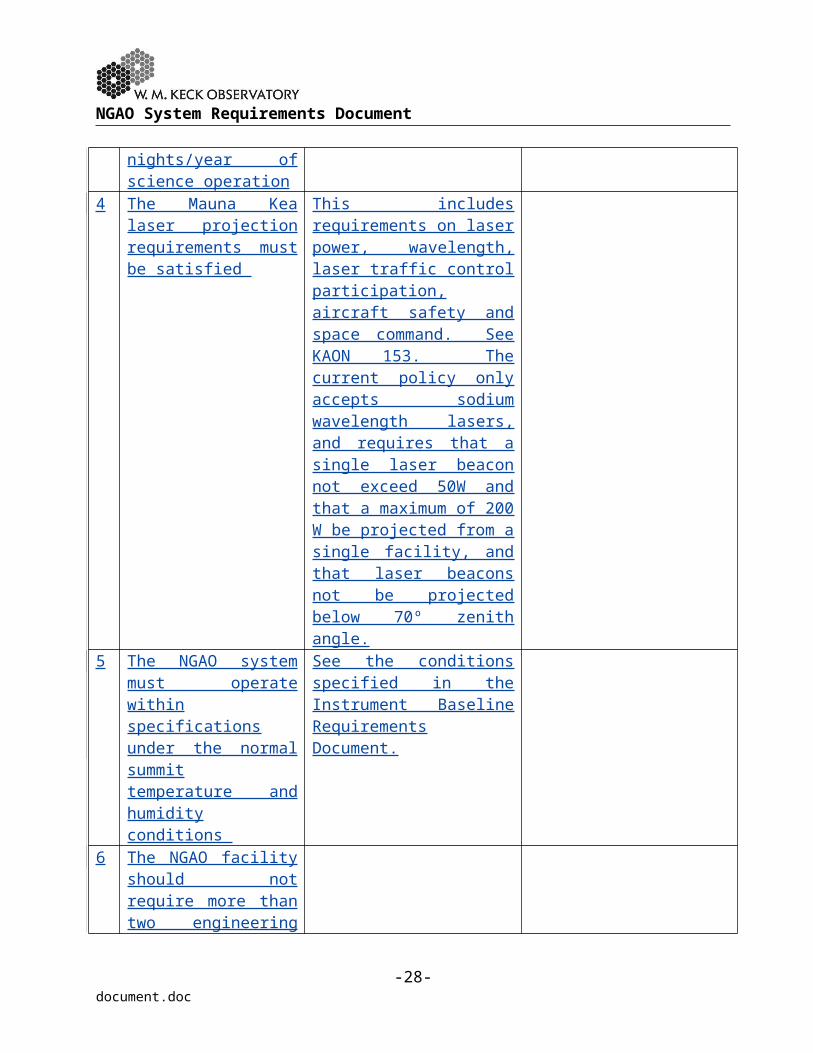
4 The Mauna Kea laser projection requirements must be satisfied
This includes requirements on laser power, wavelength, laser traffic control participation, aircraft safety and space command. See KAON 153. The current policy only accepts sodium wavelength lasers, and requires that a single laser
-18-document.doc

NGAO System Requirements Document
beacon not exceed 50W and that a maximum of 200 W be projected from a single facility, and that laser beacons not be projected below 70º zenith angle.
5 The NGAO system must operate within specifications under the normal summit temperature and humidity conditions
See the conditions specified in the Instrument Baseline Requirements Document.
6 The NGAO facility should not require more than two engineering nights per year for system maintenance
7 The NGAO facility should not routinely require more than 30 minutes of daytime telescope restriction on a science night
8 The NGAO facility should be designed to keep the total annual operational personnel and non-personnel costs below the following budgets: Four FTEs and $200k
(FY07 dollars) in non-personnel costs for the first 100 nights/year of science operations
An additional cost of 0.5 FTEs and $25k (FY07 dollars) in non-personnel costs for each additional 50 nights of science operations.
9 The NGAO facility should accommodate access for routine maintenance of the telescope
For example, access to the elevation journal, elevation wrap, bent Cassegrain platform and stairwell to the mirror cell
-19-document.doc

NGAO System Requirements Document
# Observatory Operational Requirements
Discussion
1 The NGAO system must be facility-class
Facility-class has many implications on safety, operability, reliability, maintainability, lifetime, documentation, configuration management, etc.
2 The NGAO system must complete an operations transition review where operational responsibility is transferred from development to operations
This has implications on defining transition requirements and on training.
3 The NGAO system must be capable of supporting 275 nights/year of science operation
4 The Mauna Kea laser projection requirements must be satisfied
This includes requirements on laser power, wavelength, laser traffic control participation, aircraft safety and space command. See KAON 153. The current policy only accepts sodium wavelength lasers, and requires that a single laser beacon not exceed 50W and that a maximum of 200 W be projected from a single facility, and that laser beacons not be projected below 70º zenith angle.
5 The NGAO system must operate within specifications under the normal summit temperature and humidity conditions
See the conditions specified in the Instrument Baseline Requirements Document.
6 The NGAO facility should not require more than two engineering nights per year for system maintenance
7 The NGAO facility should not routinely require more than 30 minutes of daytime telescope restriction on a science night
8 The NGAO facility should be designed to keep the total annual operational personnel and non-personnel costs below the following budgets: Four FTEs and $200k (FY07
dollars) in non-personnel costs for the first 100 nights/year of science operations
An additional cost of 0.5 FTEs
-20-document.doc

NGAO System Requirements Document
and $25k (FY07 dollars) in non-personnel costs for each additional 50 nights of science operations.
9 The NGAO facility should accommodate access for routine maintenance of the telescope
For example, access to the elevation journal, elevation wrap, bent Cassegrain platform and stairwell to the mirror cell
6.2.5 Observatory Implementation Requirements
# Observatory Implementation Requirement
Discussion
1 The time between decommissioning an AO capability on the telescope where the NGAO system is to be installed and making NGAO available for limited shared-risk science must not be longer than 6 months
Down time Impact on Interferometer and AO science at the Observatory.
2 The telescope downtime required to implement NGAO must not be longer than 5 days
# Observtory Implementation
Requirement
Discussion Based on
1 The time between decommissioning an AO capability on the telescope where the NGAO system is to be installed and making NGAO available for limited shared-risk science must not be longer than 6 months
Down time Impact on Interferometer and AO science at the Observatory.
2 The telescope downtime required to implement NGAO must not be longer than 5 days
-21-document.doc

NGAO System Requirements Document
7 OPTICAL REQUIREMENTS
7.1 Purpose and Objectives
The purpose of this section is to describe optical requirements for the performance, implementation and design of the NGAO optical system.
7.2 Performance Requirements
7.3
The following performance requirements are duplicated from the Science Performance Requirements in section 6.1.2 since these are direct optical performance requirements.
# Performance Requirement
Discussion Based on
1 Telescope plus NGAO transmission to the input of the science instruments ≥ 70% at 0.7-2.4 µm.
The wavelength range is explicitly identified in the SCRD. The transmission is a placeholder. Need to determine if we should extend this down to H (656.3 nm). May be better to write in terms of SNR.
KAON 455 (v1) Table 4
2 Goal: Telescope plus NGAO transmission to the input of the science instruments ≥ 70% at L-band.
KAON 455 (v1) Table 4 low mass stars & Galactic Center science cases
3 NGAO background, including the science instrument shall be ≤ 100% of the sky plus telescope at K-band.
The measured NIRC2 K-band background is 12.24 mag/arcsec2 . The predicted sky background is 13.46.
KAON 455 (v1) Table 4: for the asteroid science cases the background should be ≤ the current LGS background
4 Goal: NGAO background including the science instruments shall be ≤ 20% of the sky plus telescope at K-band.
KAON 455 (v1) Table 4: High z galaxies.
5 Wavefront error ≤ 140 nm rms for V ≤ 17 on-axis guide star
KAON 455 (v1) Table 4: asteroid shape & companions.
6 Wavefront error ≤ 140 nm rms for V ≤ 16 guide star ≤ 30” from science object
KAON 455 (v1) Table 4: planets around low mass stars.
-22-document.doc

NGAO System Requirements Document
7 Wavefront error ≤ 170 nm rms for objects ≤ 5” from the Galactic Center
KAON 455 (v1) Table 4: Galactic Center.
8 Encircled energy ≥ 50% within a 0.05” diameter circle at K-band for sky coverage ≥ 5%
KAON 455 (v1) Table 4: High z galaxies.
9 Encircled energy ≥ 50% within a 0.075” diameter circle at K-band for sky coverage ≥ 30%
KAON 455 (v1) Table 4: High z galaxies.
10 The companion sensitivity shall be ΔH ≥ 5.5 mag at 0.5” separation for a V ≤ 17 on-axis guide star
KAON 455 (v1) Table 4: asteroid companions.
11 The companion sensitivity shall be ΔH ≥ 13 at 1” separation for a V ≤ 16 guide star ≤ 30” from science object
KAON 455 (v1) Table 4: planets around low mass stars.
12 Sensitivity? Does this just drive transmission?
KAON 455 (v1) Table 4: planets around low mass stars.
13 H-band photometric accuracy of ≤ 0.05 mag at 0.6” for ΔH = 3 for a V ≤ 17 on-axis guide star
KAON 455 (v1) Table 4: asteroid companions.
14 H-band photometric accuracy of ≤ 0.05 mag relative to the primary star at 1” separation for ΔH = 13 for a V ≤ 16 guide star ≤ 30” from science object
KAON 455 (v1) Table 4: planets around low mass stars.
15 “Uncalibrated detector distortion < 1.5 mas”
Is this really the way we want to write this? Shouldn’t we put the high level requirement here?
KAON 455 (v1) Table 4: asteroid companions.
16 “1/10 of the PSF FWHM” Wouldn’t be better off writing this as mas?
KAON 455 (v1) Table 4: planets around low mass stars.
17 Astrometric accuracy ≤ 100 µas at K-band for objects ≤ 5” from the Galactic Center
KAON 455 (v1) Table 4: Galactic Center.
18 Radial velocity accuracy ≤ KAON 455 (v1) Table 4:
-23-document.doc
NGAO System Requirements Document
10 km/sec at K-band for objects ≤ 5” from the Galactic Center
Galactic Center.
19 Overheads between targets ≤ 10 min
KAON 455 (v1) Table 4: Asteroid size & companions, planets around low mass stars.
20 Strehl or PSF stability requirement?
TBD
The following performance requirements are derived from the Science Performance Requirements in Section 6.1.2 and the relevant performance budgets.
# Performance Requirement
Discussion Based on
1 The residual static wavefront errors from the NGAO system shall be ≤ 50 nm rms as delivered to the visible and NIR imagers
Companion sensitivity requirement & performance budget.
2 The NGAO system shall introduce ≤ TBD % polarization in the path to the TBD science instruments
3 The stability of the focal ratio produced by the NGAO system shall be TBD as delivered to the TBD science instruments
The purpose of this requirement is to have a fixed plate scale.
4 Instability must not decrease the Strehl on the visible and NIR imagers by more than 5% during any 1-hour period or over a 3 ºC temperature change
(Should look at changing the instability requirements to rms error.)
The image improvement provided by the facility must be stable over periods of hours, under stable atmospheric conditions. The wavefront sensor calibrations must be stable with time, temperature and telescope position. This requirement does not include performance degradations due to changing atmospheric conditions, or different magnitude and location of NGS or LGS. This requirement
-24-document.doc
NGAO System Requirements Document
could be tested using a point source (i.e., single mode fiber) at the NGAO system input.
5 Instability must not decrease the Strehl on the visible and NIR imagers by more than 10% during any 24-hour period or over a 5 ºC temperature change
6 The maximum intensity of any ghost images (of a science object) produced by the NGAO system shall be no more than TBD the maximum intensity of the source within the science field.
Derived from the companion sensitivity requirement.
7 The maximum intensity of any ghost images (of a science object) produced by the imaging science instruments shall be no more than TBD the maximum intensity of the source within the science field.
Derived from the companion sensitivity requirement.
# Optical Performance Requirements Discussion1 The telescope plus NGAO throughput to the
science instruments shall be ≥ 70% at 0.6-5.5 µm
2 The telescope plus NGAO throughput to the interferometer shall be ≥ 60% at 5.5-14.0 µm
3 The telescope plus NGAO emissivity to the science instrument shall be ≤ the sky emissivity at K and L-bands
4 The rms wavefront error for the combined telescope, NGAO system and visible and NIR imagers shall be TBD for the following TBD conditions
5 The rms wavefront error for the combined telescope, NGAO system and visible and
-25-document.doc

NGAO System Requirements Document
NIR IFUs shall be TBD for the following TBD conditions
6 The rms wavefront error for the combined telescope, NGAO system and deployable NIR IFU shall be TBD for the following TBD conditions
7 The rms wavefront error for the combined telescope, NGAO system and thermal NIR imager shall be TBD for the following TBD conditions
8 The rms wavefront error for the combined telescope and NGAO system delivered to the Interferometer shall be TBD for the following TBD conditions
9 The residual static wavefront errors from the NGAO system shall be ≤ 50 nm rms as delivered to the visible and NIR imagers
10 The NGAO system shall introduce ≤ TBD % polarization in the path to the TBD science instruments
11 The stability of the field produced by the NGAO system shall be TBD as delivered to the TBD science instruments
12 The rms residual tilt from the NGAO system output to the interferometer should be ≤ 0.007”
13 Instability must not decrease the Strehl on the visible and NIR imagers by more than 5% during any 1-hour period or over a 3 ºC temperature change
The image improvement provided by the facility must be stable over periods of hours, under stable atmospheric conditions. The wavefront sensor calibrations must be stable with time, temperature and telescope position. This requirement does not include performance degradations due to changing atmospheric conditions, or different magnitude and location of NGS or LGS
14 Instability must not decrease the Strehl on the visible and NIR imagers by more than 10% during any 24-hour period or over a 5 ºC temperature change
7.4 Implementation Requirements
# Optical Implementation Requirements Discussion1 The field of view provided to the science
-26-document.doc

NGAO System Requirements Document
instruments must be centered on the telescope elevation axis to within 2”
# Optical Implementation Requirement
Discussion Based on
1 The NGAO optical axis shall be coincident to the telescope’s elevation axis to ≤ TBD.
This is intended to minimize pupil and image motion.
7.5 Design Requirements
NGAO is required to provide an AO corrected beam to each of the science instruments, including the Interferometer and ‘OHANA fiber injection module. This may be accomplished with one or more AO systems. The following requirements are valid for all of these science instruments.
# Optical Design Requirements Discussion1 The focal ratio provided to the science
instruments should be TBD2 The exit pupil location provided to the
science instruments should be TBD3 The NGAO system should be capable of
correcting TBD level of non-common path aberration in the science instruments
Image sharpening can be used to correct for aberrations in the science instruments. New science instruments should be designed to have small optical aberrations. The interferometer and possible legacy instruments such as NIRC2 or OSIRIS may be allowed larger aberration budgets.
4 The peak-to-peak range of tip/tilt correction provided by NGAO shall be ≥ 3”
The existing Keck AO systems have a peak-to-peak range of 1.6” which has proven to be inadequate in windy conditions.
# Optical Design Requirement
Discussion Based on
1 The focal ratio provided to the science instruments should be TBD
2 The exit pupil location provided to the science instruments should be TBD
3 The NGAO system and science instrument
-27-document.doc

NGAO System Requirements Document
combination should be capable of keeping the field or pupil fixed on the science instrument.
4 The NGAO system shall have ≤ TBD of non-common path aberration delivered to the science instruments.
5 The NGAO system should be capable of correcting ≥ TBD nm of low spatial frequency (Zernikes 4 to 15) non-common path aberration in the science instruments.
Image sharpening can be used to correct for aberrations in the science instruments. New science instruments should be designed to have small optical aberrations. The interferometer and possible legacy instruments such as NIRC2 or OSIRIS may be allowed larger aberration budgets.
6 The peak-to-peak range of tip/tilt correction provided by NGAO shall be ≥ 3” on sky.
The existing Keck AO systems have a peak-to-peak range of 1.6” which has proven to be inadequate in windy conditions.
The following design requirements are duplicated from the Science Performance Requirements in section 6.1.2 since these are direct optical performance requirements.The following design requirements are imposed by the non-interferometric science instruments.
# Science Instrument Optical Design Requirement
Discussion Based on
1 Unvignetted contiguous fields shall be provided to the NIR and visible science imagers and single field IFUs. These fields should be centered to within 1” of the telescope’s optical axis. The maximum field size is 20”x20”.
Driven by the science requirements on the contiguous field science instruments.
2 Multiple unvignetted Driven by science
-28-document.doc

NGAO System Requirements Document
contiguous fields shall be provided to the NIR d-IFU. Each field should be ≥ 4” in diameter.
requirements on the NIR d-IFU.
3 The unvignetted field of regard provided to the NIR d-IFU shall have a total area of ≥ 6 arcmin2
and shall have a maximum off-axis distance of ≤ 1.5’ with respect to the telescope’s optical axis.
Driven by science requirements on the NIR d-IFU.
4 NGAO shall provide appropriate outputs to ≥ TBD science instruments with a switching time of ≤ 5 min.
The following design requirements are imposed by the non-interferometric science instruments. # Science Instrument Optical Design
RequirementsDiscussion
1 A wavelength range of 0.6 to 1.0 µm must be provided to the visible science instruments (imager and IFU)
2 A wavelength range of 1.0 to 2.45 µm must be provided to the NIR science instruments (imager, IFU and deployable IFU)
3 A wavelength range of 3.0 to 5.3 µm must be provided to the thermal NIR imager
4 A field of view of ≥ 20”x20” must be provided to the science imagers (visible and NIR)
5 A field of view of ≥ 12” diameter must be provided to the visible IFU
6 A field of view of ≥ 16” diameter must be provided to the NIR IFU
7 A field of regard of ≥ 1.5’ diameter must be provided to the NIR deployable IFU
8 A field of view of 25”x25” must be provided to the L and M-band imager
-29-document.doc
NGAO System Requirements Document
# Science Instrument Optical Design Requirement
Discussion Based on
1 A wavelength range of 0.7 to 1.0 µm must be provided to the visible science instruments (imager and IFU)
2 A wavelength range of 1.0 to 2.45 µm must be provided to the NIR science instruments (imager, IFU and deployable IFU)
3 A wavelength range of 3.0 to 5.3 µm must be provided to the thermal NIR imager
This is currently low priority and should be discussed if this drives the design.
4 An unvignetted field of view ≥ 20”x20” must be provided to the science imagers (visible and NIR)
Should this only be 10x10” for the visible imager?
5 An unvignetted field of view ≥ 12” diameter must be provided to the visible IFU
6 An unvignetted field of view ≥ 16” diameter must be provided to the NIR IFU
7 A field of regard of ≥ 1.5’ diameter must be provided to the NIR deployable IFU with vignetting by all sources ≤ TBD over TBD % of the field of regard
8 A field of view of 25”x25” must be provided to the L and M-band imager
Low priority.
An unvignetted science target field ≥ 3” x 3.4” shall be provided to each channel of the NIR
-30-document.doc

NGAO System Requirements Document
deployable IFUThe NGAO + deployable IFU system shall support simultaneous observations of at least two science targets separated by ≤ 5”
There is no requirement for simultaneous nearest-neighbor target distances less than 5”.
The NGAO + deployable IFU system shall support simultaneous observations of at least six science target fields inscribed within a 30” diameter fieldNGAO shall be capable of compensating for focus changes due to changing filters or modes
The following design requirements are imposed by the Interferometer and/or ‘OHANA support requirements.
# Interferometry Optical Design Requirements
Discussion
1 A wavelength range of 1.1 to 14 µm must be provided to the Interferometer
2 A wavelength range of 1.1 to 2.45 µm must be provided to the OHANA injection module
3 A field of view of ≥ 1’ diameter must be provided to the Interferometer
4 A field of view of 5” diameter must be provided to the OHANA injection module
5 NGAO must be able to support a chopping mode for the interferometer.
The nuller requires small amplitude chopping with the AO loops closed at each end of the chop for alignment purposes.
6 The interferometer output of NGAO must be polarization matched to the interferometer output of the AO system on the other telescope in order to produce ≤ 3º of differential s-p phase shift
The current KI achieves polarization matching by keeping the number, angle and coatings of all reflections the same in the beam trains from each telescope. The differential s-p phase shift in the current KI is measured at 6º resulting in a loss in V2 of 0.003.
-31-document.doc

NGAO System Requirements Document
7 The interferometer output of NGAO must have the same image rotation as the interferometer output of the AO system on the other telescope
8 The interferometer output of NGAO must have the same pupil rotation as the interferometer output of the AO system on the other telescope
9 The interferometer output of NGAO must have the same longitudinal chromatic dispersion as the interferometer output of the AO system on the other telescope
Transmissive optics fabricated from different materials can have different amounts of longitudinal chromatic dispersion resulting in the loss of fringe visibility
10 The ratio of the Strehls from the interferometer output of NGAO and the interferometer output of the AO system on the other telescope must be ≤ 1.2 and ≥ 0.9.
A Strehl mismatch of 22% or an intensity ratio of 1.22 results in a V2 loss of 0.010.
11 NGAO must be able to accommodate the accelerometers needed to support the Interferometer
On the current AO bench one accelerometer is placed near the telescope focus and another near the output to the DSM. These are used to measure vibration along the optical path and are used in the fringe tracker control system. The accelerometer acquisition system is housed in an electronics rack in the AO electronics vault.
12 NGAO or NGAO in combination with a modified DSM must be capable of supporting the laser metrology beams from the interferometer
These metrology beams are a potential source of background light on the wavefront sensors
13 NGAO must incorporate the required tools and tolerances to support alignment to the interferometer
For example, the current AO bench hosts a corner cube to aid in aligning the interferometer to the optical axis of the AO system and telescope
14 NGAO or NGAO in combination with a modified DSM must provide a collimated 100 mm diameter beam to the interferometer
In the current AO system a removable (on a translation stage) dichroic beamsplitter, located between the deformable mirror and second off-axis parabola, folds the collimated beam to the DSM
# Interferometry Optical Design Requirement
Discussion Based on
1 A wavelength range of 1.1 to 14 µm must be provided to the Interferometer
-32-document.doc

NGAO System Requirements Document
2 A wavelength range of 1.1 to 2.45 µm must be provided to the OHANA injection module
3 A field of view of ≥ 1’ diameter must be provided to the Interferometer
4 A field of view of 5” diameter must be provided to the OHANA injection module
5 NGAO must be able to support a chopping mode for the interferometer.
The nuller requires small amplitude chopping with the AO loops closed at each end of the chop for alignment purposes.
6 The interferometer output of NGAO must be polarization matched to the interferometer output of the AO system on the other telescope in order to produce ≤ 3º of differential s-p phase shift
The current KI achieves polarization matching by keeping the number, angle and coatings of all reflections the same in the beam trains from each telescope. The differential s-p phase shift in the current KI is measured at 6º resulting in a loss in V2 of 0.003.
7 The interferometer output of NGAO must have the same image rotation as the interferometer output of the AO system on the other telescope
8 The interferometer output of NGAO must have the same pupil rotation as the interferometer output of the AO system on the other telescope
9 The interferometer output of NGAO must have the same longitudinal chromatic dispersion as the interferometer output of the AO system on the
Transmissive optics fabricated from different materials can have different amounts of longitudinal chromatic dispersion resulting in the loss of fringe visibility
-33-document.doc

NGAO System Requirements Document
other telescope10 The ratio of the Strehls
from the interferometer output of NGAO and the interferometer output of the AO system on the other telescope must be ≤ 1.2 and ≥ 0.9.
A Strehl mismatch of 22% or an intensity ratio of 1.22 results in a V2 loss of 0.010.
11 NGAO must be able to accommodate the accelerometers needed to support the Interferometer
On the current AO bench one accelerometer is placed near the telescope focus and another near the output to the DSM. These are used to measure vibration along the optical path and are used in the fringe tracker control system. The accelerometer acquisition system is housed in an electronics rack in the AO electronics vault.
12 NGAO or NGAO in combination with a modified DSM must be capable of supporting the laser metrology beams from the interferometer
These metrology beams are a potential source of background light on the wavefront sensors
13 NGAO must incorporate the required tools and tolerances to support alignment to the interferometer
For example, the current AO bench hosts a corner cube to aid in aligning the interferometer to the optical axis of the AO system and telescope
14 NGAO or NGAO in combination with a modified DSM must provide a collimated 100 mm diameter beam to the interferometer
In the current AO system a removable (on a translation stage) dichroic beamsplitter, located between the deformable mirror and second off-axis parabola, folds the collimated beam to the DSM
15 The rms residual tilt at the NGAO system output to the interferometer should be ≤ 0.007” for TBD guide star.
-34-document.doc

NGAO System Requirements Document
-35-document.doc

NGAO System Requirements Document
8 MECHANICAL REQUIREMENTS
8.1 Purpose and Objectives
The purpose of this section is to describe mechanical requirements for the performance, implementation and design of the NGAO mechanical systems.
8.2 Performance Requirements
# Mechanical Performance Requirement
Discussion
1 The NGAO AO system shall not exceed a thermal dissipation budget, into the dome environment, of 100 W
2 The NGAO laser system shall not exceed a thermal dissipation budget, into the dome environment, of 100 W
3 The NGAO AO system shall not exceed a thermal dissipation budget at the top-end of the telescope, into the dome environment, of 50 W
# Mechanical Performance Requirement
Discussion Based on
1 The NGAO AO system shall not exceed a thermal dissipation budget, into the dome environment, of 100 W
2 The NGAO laser system shall not exceed a thermal dissipation budget, into the dome environment, of 100 W
3 The NGAO AO system shall not exceed a thermal dissipation budget at the top-end of the telescope, into the dome
-36-document.doc

NGAO System Requirements Document
environment, of 50 W
8.3 Implementation Requirements
# Mechanical Implementation Requirement
Discussion
1 The NGAO facility must allow a means to install new science instruments
For example, if a new instrument can only be installed with the overhead crane then a means of removing the appropriate portion of the AO enclosure roof would be required.
# Mechanical Implementation
Requirement
Discussion Based on
1 The NGAO facility must allow a means to install new science instruments
For example, if a new instrument can only be installed with the overhead crane then a means of removing the appropriate portion of the AO enclosure roof would be required.
8.4 Design Requirements
# Mechanical Design Requirement Discussion1 The maximum weight of the AO
system on the Nasmyth platform shall not exceed 10,000 kg
The weight requirements are imposed by limits on what the telescope can support at various locations without changing its performance.
2 The maximum weight of the laser facility on the azimuth rotating part of the telescope shall not exceed 10,000 kg
3 The maximum weight of the beam transport system on the elevation portion of the telescope shall not exceed 150 kg
4 The maximum weight of the laser launch facility in the top-end module shall not exceed 150 kg
5 If mounted behind the f/15 secondary mirror, the launch telescope facility must allow for the removal, storage and installation of the f/15 secondary
-37-document.doc
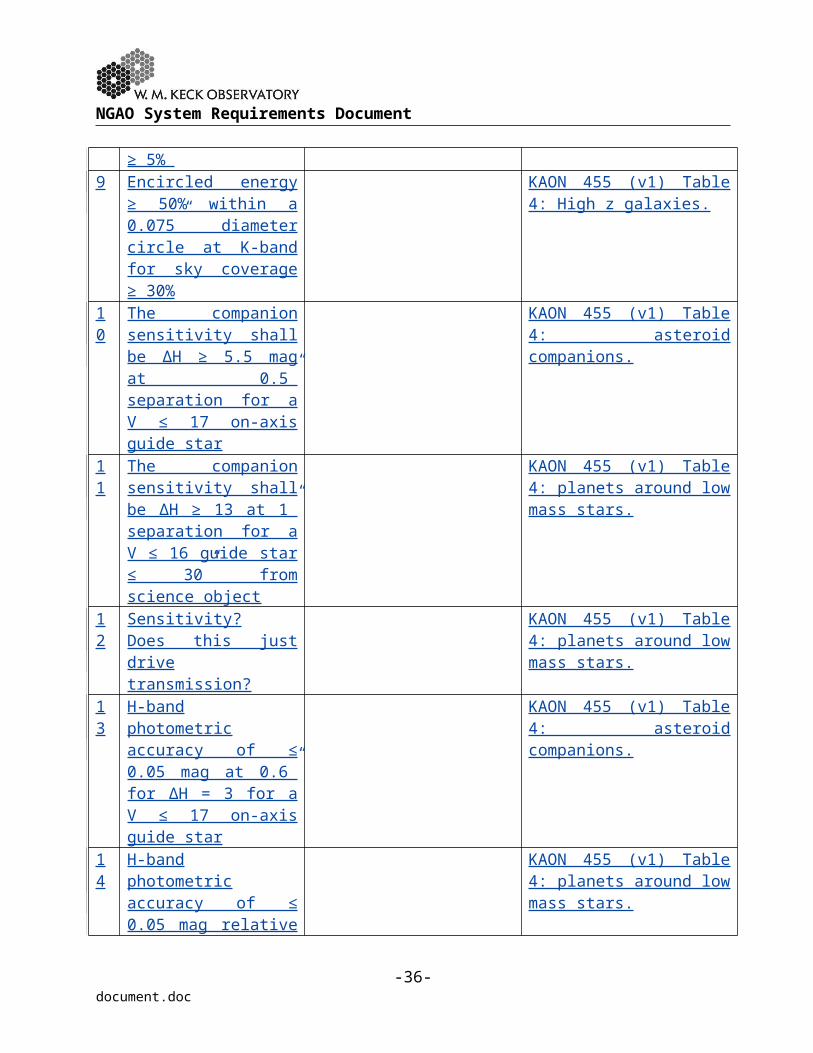
NGAO System Requirements Document
module6 If mounted behind the f/15
secondary mirror, the launch telescope facility must not extend beyond the module in the x,y-directions and must not extend more than 1 m beyond the top of the telescope structure.
7 The NGAO facility must fit within the mechanical constraints of a Nasmyth platform (nominally the Keck II left Nasmyth platform)
8 The NGAO facility must provide access and space for the installation of each science instrument and a mechanical interface on which to mount each instrument
9 The NGAO facility must provide access for routine maintenance of the elevation bearing, elevation wrap, bent Cassegrain platform and mirror cell stairwell
10 The required glycol flow rate and pressure for cooling the NGAO facility shall not exceed TBD and TBD, respectively
# Mechanical Design Requirement
Discussion Based on
1 The maximum weight of the AO system on the Nasmyth platform shall not exceed 10,000 kg
The weight requirements are imposed by limits on what the telescope can support at various locations without changing its performance.
2 The maximum weight of the laser facility on the azimuth rotating part of the telescope shall not exceed 10,000 kg
3 The maximum weight of the beam transport system on the elevation portion of the telescope shall not
-38-document.doc

NGAO System Requirements Document
exceed 150 kg4 The maximum weight of
the laser launch facility in the top-end module shall not exceed 150 kg
5 If mounted behind the f/15 secondary mirror, the launch telescope facility must allow for the removal, storage and installation of the f/15 secondary module
6 If mounted behind the f/15 secondary mirror, the launch telescope facility must not extend beyond the module in the x,y-directions and must not extend more than 1 m beyond the top of the telescope structure.
7 The NGAO facility must fit within the mechanical constraints of a Nasmyth platform (nominally the Keck II left Nasmyth platform)
8 The NGAO facility must provide access and space for the installation of each science instrument and a mechanical interface on which to mount each instrument
9 The NGAO facility must provide access for routine maintenance of the elevation bearing, elevation wrap, bent Cassegrain platform and mirror cell stairwell
10 The required glycol flow rate and pressure for cooling the NGAO facility
-39-document.doc

NGAO System Requirements Document
shall not exceed TBD and TBD, respectively
-40-document.doc

NGAO System Requirements Document
9 ELECTRONIC/ELECTRICAL REQUIREMENTS
9.1 Purpose and Objectives
The purpose of this section is to describe electronic and electrical requirements for the performance, implementation and design of the NGAO electronic and electrical systems.
9.2 Performance Requirements
9.3 Implementation Requirements
9.4 Design Requirements
# Electrical Performance Requirement
Discussion
1 The entire NGAO facility must not exceed a total electrical power requirement of 30 kW
2 The NGAO facility cabling through the azimuth wrap must not require an area of more than TBD
3 The NGAO facility cabling through the left Nasmyth elevation wrap must not exceed an area of more than TBD
4 The NGAO facility cabling through the right Nasmyth elevation wrap must not exceed an area of more than TBD
# Electrical Performance Requirement
Discussion Based on
1 The entire NGAO facility must not exceed a total electrical power requirement of 30 kW
2 The NGAO facility cabling through the azimuth wrap must not require an area of more than TBD
3 The NGAO facility cabling through the left Nasmyth elevation wrap
-41-document.doc

NGAO System Requirements Document
must not exceed an area of more than TBD
4 The NGAO facility cabling through the right Nasmyth elevation wrap must not exceed an area of more than TBD
-42-document.doc

NGAO System Requirements Document
10 SAFETY REQUIREMENTS
10.1 Purpose and Objectives
Safety is the paramount concern for all activities at the observatory. The purpose of this section is to provide requirements related to specific safety concerns during the operation and handling of NGAO.
10.2 Scope
The general Observatory safety requirements that are also applicable to NGAO are already contained in the Instrumentation Baseline Requirements Document. This section covers the additional laser safety and laser projection safety requirements.
Adequate earthquake restraints are also required for all systems.
10.3 Laser Safety Requirements
A safety system will be implemented to ensure the safe use of the laser. This safety system will include both engineering and administrative/procedural controls to assure safe operations. The system will apply ANSI Z136.1 and Z136.6 standards for safe use of laser for indoor and outdoor.
The NGAO system will conform to OSHA and local codes in addition to codes specified for each subsystem.
10.4 Laser Projection Safety Requirements
This section covers the additional requirements on safety for projecting the laser beams outside the dome.
10.4.1 Aircraft Safety
An aircraft safety system compliant with FAA requirements must be implemented and approved by the FAA.
10.4.2 Space Command
A system must be implemented to facilitate effective communication with U.S. Space Command of projection dates and targets, and to ensure that no projection occurs on a target without Space Command approval. This requirement may be deleted if it is determined that Space Command approval is no longer required.
-43-document.doc

NGAO System Requirements Document
11 SOFTWARE REQUIREMENTS
11.1 Purpose and Objectives
The software requirements section describes requirements for performance, implementation and design.
11.2 Scope
Unless otherwise indicated all of the requirements of this section apply to all software components of NGAO.
11.3 Performance Requirements
11.4 Implementation Requirements
11.5 Design Requirements
# Software Design Requirements Discussion1 The NGAO system must be able to support
the external interfaces supported by the existing AO systems
The external keywords and EPICS channels used by the existing AO systems are documented in KAON 315, Summary of External Interfaces in the Current WFC and Implications for the NGWFC Design”
2 The NGAO system must be able to accept tip/tilt offloads from the science instrument
3 The NGAO system must be able to acquire and configure the AO system based on the star magnitude and spectral type provided in the target list
4 NGAO must be able to support a chopping mode for the Nuller mode of the interferometer
-44-document.doc

NGAO System Requirements Document
12 INTERFACE REQUIREMENTS
12.1 Purpose and Objectives
This section is reserved for interface requirements that are not addressed by other portions of the document.
12.2 Performance Requirements
12.3 Implementation Requirements
12.4 Design Requirements
12.4.1 Optical Interface
12.4.2 Mechanical Interface
# Mechanical Interface Requirements Discussion1 An agreed upon kinematic interface
between the NGAO opto-mechanical systems and the telescope structure must be provided
Kinematic interfaces are proposed so that thermal changes do not distort optical benches.
2 NGAO must be compatible with the interferometer dual star module (DSM) or replicate its functionality
The current Keck AO systems interface to the interferometer via an opto-mechanical system known as the DSM.
3 An agreed upon mechanical interface between the NGAO electronics and the telescope must be provided
4 An agreed upon mechanical interface between any NGAO enclosures and the telescope must be provided.
5 An agreed upon mechanical interface between any NGAO glycol cooled systems and the telescope instrument and/or facility glycol systems must be provided
6 An agreed upon mechanical interface between any NGAO CCR-cooled systems must be provided
12.4.3 Electrical/Electronic Interface
# Electrical Interface Requirements Discussion1 An agreed upon electrical interface for
power between NGAO systems and the Observatory/telescope must be provided
The Observatory is responsible for providing power to the various NGAO system locations.
-45-document.doc

NGAO System Requirements Document
2 An agreed upon interface for communication between NGAO systems and the Observatory/telescope must be provided
The Observatory is responsible for the implementation of all cables between NGAO system locations. The Observatory must in particular approve all cabling required to go in the elevation or azimuth wraps.
12.4.4 Software Interface
# Software Interface Requirements Discussion1 An interface should be provided to offload
tip/tilt errors to telescope pointing through the telescope drive and control system (DCS)
2 An interface should be provided to offload focus errors to the secondary mirror piston through DCS
3 An interface should be provided to offload coma errors to the secondary mirror tilt through DCS
4 An interface should be provided to offload segment stacking errors to the active control system (ACS)
5 An interface should be provided to write all appropriate NGAO keywords to the science instrument FITS header
6 An interface should be provided to allow NGAO to read/write NGAO science instrument keywords
-46-document.doc

NGAO System Requirements Document
13 RELIABILITY REQUIREMENTS
13.1 Purpose
A process should take place to confirm that the NGAO system will provide a high level of reliability for a 10 year lifetime.
13.2 Scope
Unless otherwise indicated all of the requirements of this section apply to all components of NGAO.
13.3 Performance
System downtime should be minimized by a combination of component reliability, ease of repair, maintenance and appropriate sparing.
# Reliability Performance Requirements Discussion1 ≤ 5% of observing time lost to problems This includes any loss to an exposure in
progress and the time to start the next exposure after recovering from a fault
2 The median time between faults during observing time should be ≥ 3 hrs
Frequent short duration faults are not acceptable since they have a high impact on science productivity
14 SPARES REQUIREMENTS
TBD
15 SERVICE AND MAINTENANCE REQUIREMENTS
TBD
-47-document.doc

NGAO System Requirements Document
16 DOCUMENTATION REQUIREMENTS
The documentation requirements are defined in the Instrumentation Baseline Requirements Document.
16.1 Documentation Package
16.2 Drawings
16.3 Electrical/Electronic Documentation
16.4 Software
-48-document.doc

NGAO System Requirements Document
17 GLOSSARY
Table 2 defines the acronyms and specialized terms used in this document.
Table 2 Glossary of TermsTerm DefinitionACS Active Control SystemANSI American National Standards InstituteAO Adaptive OpticsDCS Drive and Control SystemDSM Dual Star ModuleFAA Federal Aviation AdministrationFOV Field Of ViewFWHM Full Width at Half Maximum. IFU Integral Field UnitKAON Keck Adaptive Optics NoteKI Keck InterferometerLGS Laser Guide StarMTBF Mean Time Between FailuresNGAO Next Generation Adaptive OpticsNGS Natural Guide StarNIR Near InfraRedNIRC2 NIR Camera 2NIRSPEC NIR SPECtrometer‘OHANA Optical Hawaiian Array for Nanoradian AstronomyOSHA Occupational Safety and Health AdministrationOSIRIS OH-Suppression InfraRed Integral field SpectrographTBC To Be CompletedTBD To Be DeterminedWMKO W. M. Keck Observatory
-49-document.doc