moteworks getting started guide - memsic · moteworks getting started guide doc. # 7430-0102-01...
TRANSCRIPT

MEMSIC, Inc., 1759 McCarthy Blvd, Milpitas, CA 95035 Tel: 408-964-9700, Fax: 408-854-7702
Email: [email protected], website: www.memsic.com
MoteWorks Getting Started Guide Revision G, March 2012 PN: 7430-0102-01

© 2005-20012 Memsic, Inc. All rights reserved. Information in this document is subject to change without notice.
Memsic, MoteWorks, MICA, TrueMesh and XMesh are registered trademarks of Memsic, Inc. Other product and trade names are trademarks or registered trademarks of their respective holders.

MoteWorks Getting Started Guide
Doc. # 7430-0102-01 Rev. G Page i
1 Introduction .............................................................................................................................1 1.1 MoteWorks Network Landscape .................................................................................... 1
1.2 Low-Power Operating System – TinyOS ...................................................................... 3
1.3 Software Development Tools ........................................................................................ 3
2 Installation of MoteWorks .....................................................................................................4 2.1 What You Need for Installation ..................................................................................... 4
2.2 Installing from the CDROM .......................................................................................... 5
2.3 MoteWorks Installation Structure .................................................................................. 8
2.4 Uninstalling MoteWorks .............................................................................................. 10
3 Programming Environment Customization .......................................................................11 3.1 Programmer’s Notepad 2 ............................................................................................. 11
3.2 Cygwin ......................................................................................................................... 13
3.3 Setting Aliases ............................................................................................................. 13
3.4 Compiling MoteWorks Applications ............................................................................ 14
3.5 Programming Boards ................................................................................................... 14
3.6 Installing MoteWorks Applications into a Mote .......................................................... 16
3.7 Setting the Group ID and Node Address for the Mote Network ................................. 17
3.8 The MakeMemslocal file ............................................................................................. 18
3.9 Radio Frequencies ........................................................................................................ 23
3.10 Automated Build Tools ............................................................................................ 23
3.11 Mote Programming Tools ........................................................................................ 24
3.12 TinyOS Interoperability and Tree Management ...................................................... 25
3.13 Compiling Utilities ................................................................................................... 26
3.14 XSniffer .................................................................................................................... 27
4 Introduction to TinyOS and nesC .......................................................................................29 4.1 TinyOS ......................................................................................................................... 29
4.2 The nesC Language ..................................................................................................... 31
5 First Steps in nesC Programming .......................................................................................33 5.1 Hardware Requirements .............................................................................................. 33
5.2 A simple nesC program: MyApp ................................................................................. 33
5.3 A Closer Look at MyApp ............................................................................................ 38
5.4 Generating the Component Structure Documentation ................................................. 44
6 A Simple Sensing Application..............................................................................................46 6.1 Hardware Requirements .............................................................................................. 46
6.2 A Simple Sensing Application: MyApp ...................................................................... 46

MoteWorks Getting Started Guide
Page ii Doc. # 7430-0102-01 Rev. G
6.3 A Closer Look at MyApp ............................................................................................ 53
6.4 XSensor Applications Supported in MoteWorks .......................................................... 56
7 XMesh enabled Sensing Application ...................................................................................58 7.1 Hardware Requirements .............................................................................................. 58
7.2 An XMesh enabled Sensing application: MyApp........................................................ 58
7.3 A Closer Look at MyApp ............................................................................................ 68
7.4 XMesh Applications Supported in MoteWorks ............................................................ 70
8 XMesh Advanced Features ..................................................................................................72 8.1 Hardware Requirements .............................................................................................. 72
8.2 End-to-End Acknowledgements: MyApp from the subdirectory /lesson_5 ................ 72
8.3 A Closer Look at MyApp ............................................................................................ 73
8.4 Downstream Command Processing: MyApp from the subdirectory /lesson_6 ........... 74
8.5 A Closer Look at MyApp ............................................................................................ 77
9 Data Logging Application ....................................................................................................79 9.1 Hardware Requirements .............................................................................................. 79
9.2 Using the external flash: MyApp from the subdirectory /lesson_7 ............................. 79
9.3 A Closer Look at MyApp ............................................................................................ 81
9.4 Conclusion ................................................................................................................... 83
10 Appendix A: Cygwin Command Reference ....................................................................84
11 Appendix B: Copyright Notice and Support Policy........................................................85 11.1 Copyright Notice: ..................................................................................................... 85
11.2 Support Policy .......................................................................................................... 85
11.3 Known Issues ........................................................................................................... 85
11.4 Disclaimer: ............................................................................................................... 85
MoteWorks Getting Started Guide
Doc. # 7430-0102-01 Rev. G Page iii
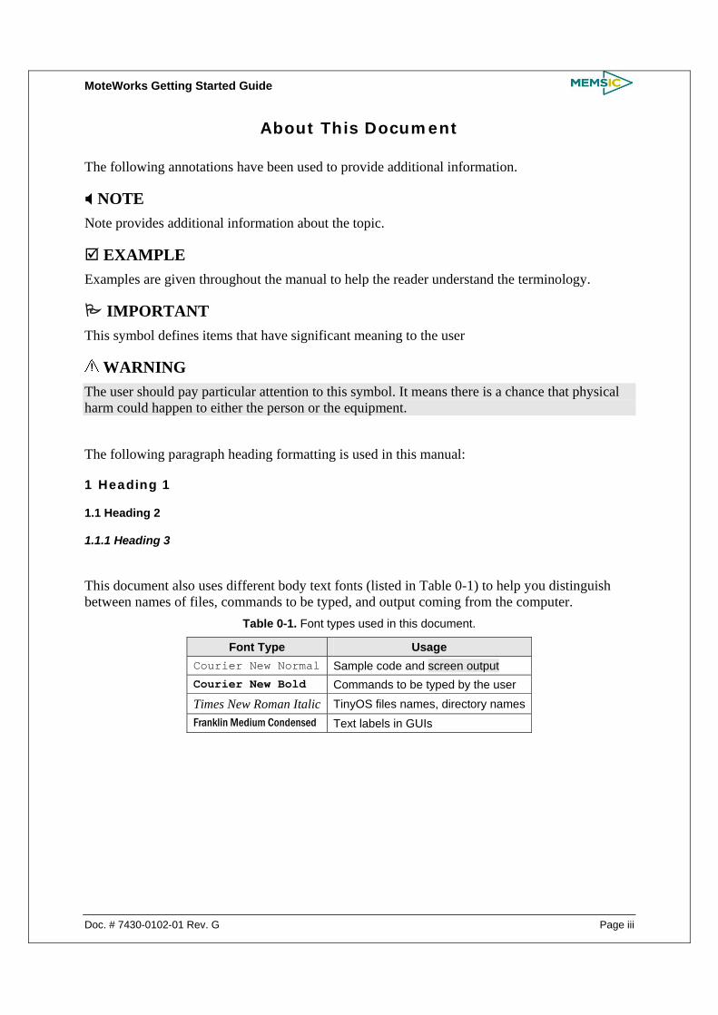
About This Document
The following annotations have been used to provide additional information.
NOTE Note provides additional information about the topic.
EXAMPLE Examples are given throughout the manual to help the reader understand the terminology.
IMPORTANT This symbol defines items that have significant meaning to the user
WARNING The user should pay particular attention to this symbol. It means there is a chance that physical harm could happen to either the person or the equipment.
The following paragraph heading formatting is used in this manual:
1 Heading 1
1.1 Heading 2
1.1.1 Heading 3
This document also uses different body text fonts (listed in Table 0-1) to help you distinguish between names of files, commands to be typed, and output coming from the computer.
Table 0-1. Font types used in this document.
Font Type Usage Courier New Normal Sample code and screen output Courier New Bold Commands to be typed by the user
Times New Roman Italic TinyOS files names, directory names Franklin Medium Condensed Text labels in GUIs


MoteWorks Getting Started Guide
Doc. # 7430-0102-01 Rev. G Page 1
1 Introduction
MoteWorks™ is the end-to-end enabling platform for the creation of wireless sensor networks. The optimized processor/radio hardware, industry-leading mesh networking software, gateway server middleware and client monitoring and management tools support the creation of reliable, easy-to-use wireless OEM solutions. OEMs are freed from the detailed complexities of designing wireless hardware and software enabling them to focus on adding unique differentiation to their applications while bringing innovative solutions to market quickly.
1.1 MoteWorks Network Landscape A wireless network deployment is composed of the three distinct software tiers:
1. The Mote Tier, where XMesh resides, is the software that runs on the cloud of sensor nodes forming a mesh network. The XMesh software provides the networking algorithms required to form a reliable communication backbone that connects all the nodes within the mesh cloud to the server. (Refer to XMesh User’s Manual)
2. The Server Tier is an always-on facility that handles translation and buffering of data coming from the wireless network and provides the bridge between the wireless Motes and the internet clients. XServe and XOtap are server tier applications that can run on a PC or Stargate. (Refer to XServe User’s Manual)
3. The Client Tier provides the user visualization software and graphical interface for managing the network. Memsic provides free client software called MoteView, but XMesh can be interfaced to custom client software as well. (Refer to MoteView User’s Manual)
Figure 1-1. XMesh Landscape
The software platform provided with MoteWorks™ is optimized for low-power battery-operated

MoteWorks Getting Started Guide
Page 2 Doc. # 7430-0102-01 Rev. G
networks and provides an end-to-end solution across all tiers of wireless sensor networking applications.
1.1.1 XMesh Mote Tier XMesh is a full featured multi-hop, ad-hoc, mesh networking protocol developed by Memsic for wireless networks. An XMesh network consists of nodes (Motes) that wirelessly communicate to each other and are capable of hopping radio messages to a base station where they are passed to a PC or other client. The hopping effectively extends radio communication range and reduces the power required to transmit messages. By hopping data in this way, XMesh can provide two critical benefits: improved radio coverage and improved reliability. Two nodes do not need to be within direct radio range of each other to communicate. A message can be delivered to one or more nodes in-between which will route the data. Likewise, if there is a bad radio link between two nodes, that obstacle can be overcome by rerouting around the area of bad service. Typically the nodes run in a low power mode, spending most of their time in a sleep state, in order to achieve multi-year battery life.
XMesh provides a TrueMesh networking service that is both self-organizing and self-healing. XMesh can route data from nodes to a base station (upstream) or downstream to individual nodes. It can also broadcast within a single area of coverage or arbitrarily between any two nodes in a cluster. QOS (Quality of Service) is provided by either a best effort (link level acknowledgement) and guaranteed delivery (end-to-end acknowledgement). Also, XMesh can be configured into various power modes including HP (high power), LP (low power), and ELP (extended low power).
1.1.2 XServe Server Tier XServe serves as the primary gateway between wireless mesh networks and enterprise applications interacting with the mesh. At its core, XServe provides services to route data to and from the mesh network with higher level services to parse, transform and process data as it flows between the mesh and the outside applications. Higher level services are customizable using XML based configuration files and loadable plug-in modules.
XServe offers multiple communication inputs for applications wishing to interact with XServe or the mesh network. Users can interact with XServe through a terminal interface applications can access the network directly or through a powerful XML RPC command interface.
1.1.3 MoteView Client Tier MoteView is the client user interface that enables MoteWorks™ to deliver an end-to-end solution across all tiers of wireless sensor networks. MoteView displays the information from the network to developers or end-users. The entire network or individual nodes can be displayed and analyzed in graphical charting or textual format. MoteView’s playback capability allows historical viewing of network status and sensor readings over time, and is based on the logging information stored in XServe. MoteView’s analysis capabilities allow automatic e-mail alerts when user-definable conditions are met. For example, if RF links are re-routed because of changes in the environment or sensor readings exceed a specified threshold, an e-mail will alert an operator or field technician via PDA or mobile phone. MoteView enables end-users to optimize network layout and configuration, analyze sensor information interactively and then take corrective action. MoteView provides an interface to remotely configure motes in the wireless network. Each node can be individually updated with configuration parameters provided

MoteWorks Getting Started Guide
Doc. # 7430-0102-01 Rev. G Page 3
by the mote. This makes it transparent for the user of an installed wireless sensor network to configure motes, e.g. change frequency of sensor readings, without requiring any programming knowledge. MoteView also has built-in support for Memsic’s entire range of sensor boards, enabling very fast prototyping. If custom sensor boards are required for an application, these boards can be integrated for management in MoteView as well.
1.2 Low-Power Operating System – TinyOS MoteWorks™ includes TinyOS, the open-source operating system originally developed by University of California, Berkeley. TinyOS has developed a broad user community with thousands of developers, making it the standard operating system for wireless sensor networking in the research community. It is also the most widely-deployed wireless sensor network operating system for commercial applications. TinyOS is a component-based, event-driven operating system designed from the ground up for low-power devices with small memory footprint requirements.
TinyOS supports microprocessors ranging from 8-bit architectures with as little as 2 KB of RAM to 32-bit processors with 32 MB of RAM or more. It provides a well-defined set of APIs for application programming. These APIs provide access to the computing capabilities of the sensor node, allowing for intelligence within the network. Using these capabilities, sensor data can be preprocessed on the node, optimizing both network throughput and battery life by avoiding unnecessary send and receive messages.
1.3 Software Development Tools MoteWorks is provided with a set of software development tools for custom Mote applications, including custom sensor board drivers, sensor signal conditioning and processing and message handlers. MoteWorks includes an optimized cross-compiler for the target mote platform and an advanced editor for TinyOS application development. MoteWorks automatically installs and configures these development tools for quick set-up and rapid start of development.

MoteWorks Getting Started Guide
Page 4 Doc. # 7430-0102-01 Rev. G
2 Installation of MoteWorks
This chapter describes how to install MoteWorks on a Windows®-based PC from the CD that comes with the product. You will learn
• Installing MoteWorks and its tools
• MoteWorks installation tree structure
• How to uninstall MoteWorks
The issues that come up during installation such as choosing an installation directory and installing with other versions of TinyOS, nesC, and Cygwin are also covered here. Following the installation, read Chapter 3 which covers many important programming topics, instructions for compiling and downloading the application firmware into your Motes, and useful programming environment customizations.
2.1 What You Need for Installation
Memsic’s MoteWorks CD-ROM
A Windows-based PC Operating System: Microsoft Windows (XP, 2000, NT,7) 1 GB or more of free space in destination drive 550 MB or more of space in C drive, regardless of destination drive
The MoteWorks InstallShield Wizard setup offers the following software packages:
TinyOS and MoteWorks Tools An event-driven OS for wireless sensor networks; tools for debugging
nesC compiler An extension of C-language designed for TinyOS
Cygwin A Linux-like environment for Windows
AVR Tools A suite of software development tools for Atmel’s AVR processors
Programmer’s notepad IDE for code compilation and debugging
XSniffer Network Monitoring Tool for the RF environment
MoteConfig GUI environment for Mote Programming and OTAP
Graphviz To view files made from make docs

MoteWorks Getting Started Guide
Doc. # 7430-0102-01 Rev. G Page 5
2.2 Installing from the CDROM
IMPORTANT Prior to installing MoteWorks, it is strongly recommended that you shut down all the programs running on your computer.
1. Insert MoteWorks CD into the PC’s CD-ROM drive and double-click on
MoteWorks_<version>_Setup.exe
2. At the Welcome to the MoteWorks
Setup Wizard window, click on Next>.
3. The installer will check for previously
installed Cygwin and if detected will
display the message. Check the
appropriate Cygwin option and click
on Next>.

MoteWorks Getting Started Guide
Page 6 Doc. # 7430-0102-01 Rev. G
4. At the License Agreement page, you
should read and check on “I accept the
agreement. Click on Next>.
5. Specify the destination directory for
the MoteWorks (default is C:\Memsic)
and click on Next>. MoteWorks should
not be installed to C:\Program
Files\Memsic
6. In the Select MoteWorks Components
dialog, select Full installation from the
drop down (recommended) and check
all the options. If you are upgrading
the MoteWorks components over a
previous version, then you can check
only the relevant components. Click on
Next>.

MoteWorks Getting Started Guide
Doc. # 7430-0102-01 Rev. G Page 7
7. The next window will display the
selections you specified. Verify and
click on Install to begin installation
process.
8. You may get the Cygwin Setup
warning shown on the right. Click on Yes.
9. The windows shown will appear as the
installation progresses. Wait patiently
for further instructions.
10. The Setup Wizard will then install Graphviz utility. Wait patiently for further instructions.

MoteWorks Getting Started Guide
Page 8 Doc. # 7430-0102-01 Rev. G
11. The next step is the installation of
MoteConfig. Click Next> on the
welcome window. The installer will
guide you through the rest of the
process. (MoteConfig gets installed
under the default folder
C:\ Memsic\MoteConfig)
12. Upon successful installation, you will
see this message. Click on Finish to exit
set-up. You may restart the computer
now.
2.3 MoteWorks Installation Structure All the MoteWorks components such as apps/, doc/, tools/, and tos/ directories are located under <install dir>/cygwin/opt/MoteWorks/. In addition the Makefile is in this folder. The environment variables for TOSROOT is set to <install dir>. Typically the default <install dir> is the C:\ Memsic

MoteWorks Getting Started Guide
Doc. # 7430-0102-01 Rev. G Page 9
(a) MoteWorks top level directory structure
(b) MoteWorks and subdirectories
(c) apps and subdirectories
apps
examples
general
tutorials
xmesh
Example applications described in XMesh manual
Basic applications such as Blink and XSniffer
Applications described in Getting Started Guide
Multi-hop apps for various sensorboards
Single-hop apps for various sensorboardsxsensor
apps
examples
general
tutorials
xmesh
Example applications described in XMesh manual
Basic applications such as Blink and XSniffer
Applications described in Getting Started Guide
Multi-hop apps for various sensorboards
Single-hop apps for various sensorboardsxsensor
MoteWorks
apps
make
doc
tools
tos
XMesh, XSensor applications and example programs
nesC Compile utilities for different processor platforms
Documents generated by make utility
Developers utilities and programs
TinyOS “operating system,” modules, and interfaces
MoteWorks
apps
make
doc
tools
tos
XMesh, XSensor applications and example programs
nesC Compile utilities for different processor platforms
Documents generated by make utility
Developers utilities and programs
TinyOS “operating system,” modules, and interfaces
MoteWorks Getting Started Guide
Page 10 Doc. # 7430-0102-01 Rev. G
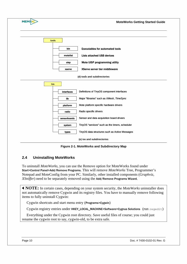
(d) tools and subdirectories
(e) tos and subdirectories
Figure 2-1. MoteWorks and Subdirectory Map
2.4 Uninstalling MoteWorks
To uninstall MoteWorks, you can use the Remove option for MoteWorks found under Start>Control Panel>Add/Remove Programs. This will remove MoteWorks Tree, Programmer’s Notepad and MoteConfig from your PC. Similarly, other installed components (Graphviz, XSniffer) need to be separately removed using the Add/Remove Programs Wizard.
NOTE: In certain cases, depending on your system security, the MoteWorks uninstaller does not automatically remove Cygwin and its registry files. You have to manually remove following items to fully uninstall Cygwin: Cygwin shortcuts and start menu entry (Programs>Cygwin)
Cygwin registry entries under HKEY_LOCAL_MACHINE>Software>Cygnus Solutions (run regedit)
Everything under the Cygwin root directory. Save useful files of course; you could just rename the cygwin root to say, cygwin-old, to be extra safe.
tos
interfaces
lib
platform
sensorboards
system
Definitions of TinyOS component interfaces
Major “libraries” such as XMesh, TimeSync
Mote platform specific hardware drivers
Sensor and data acquisition board drivers
TinyOS “services” such as the timers, scheduler
types TinyOS data structures such as Active Messages
radio Radio specific drivers
tools
bin
motelist
uisp
xserve
Executables for automated tools
Lists attached USB devices
Mote UISP programming utility
XServe server tier middleware
tools
bin
motelist
uisp
xserve
Executables for automated tools
Lists attached USB devices
Mote UISP programming utility
XServe server tier middleware
MoteWorks Getting Started Guide
Doc. # 7430-0102-01 Rev. G Page 11
3 Programming Environment Customization
In this chapter, you will learn:
Customizing Programmer’s Notepad Cygwin interface Compiling and Programming Tools Environment variables Interoperability between TinyOS 1.1.10 and MoteWorks 2.1
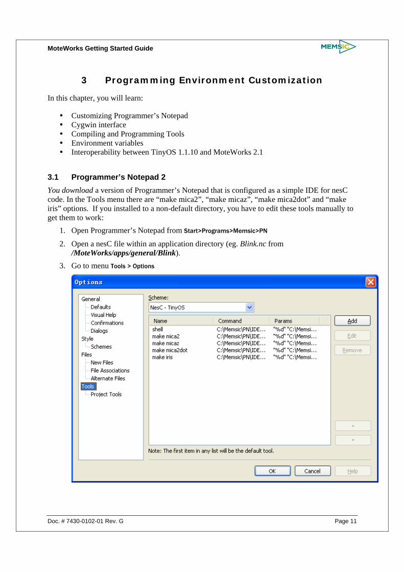
3.1 Programmer’s Notepad 2 You download a version of Programmer’s Notepad that is configured as a simple IDE for nesC code. In the Tools menu there are “make mica2”, “make micaz”, “make mica2dot” and “make iris” options. If you installed to a non-default directory, you have to edit these tools manually to get them to work:
1. Open Programmer’s Notepad from Start>Programs>Memsic>PN
2. Open a nesC file within an application directory (eg. Blink.nc from /MoteWorks/apps/general/Blink).
3. Go to menu Tools > Options
MoteWorks Getting Started Guide
Page 12 Doc. # 7430-0102-01 Rev. G
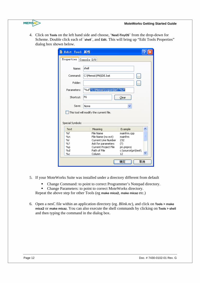
4. Click on Tools on the left hand side and choose, ‘NesC-TinyOS’ from the drop-down for Scheme. Double click each of `shell`, and Edit. This will bring up “Edit Tools Properties” dialog box shown below.
5. If your MoteWorks Suite was installed under a directory different from default
Change Command: to point to correct Programmer’s Notepad directory. Change Parameters: to point to correct MoteWorks directory.
Repeat the above step for other Tools (eg make mica2, make micaz etc.) 6. Open a nesC file within an application directory (eg. Blink.nc), and click on Tools > make
mica2 or make micaz. You can also execute the shell commands by clicking on Tools > shell and then typing the command in the dialog box.

MoteWorks Getting Started Guide
Doc. # 7430-0102-01 Rev. G Page 13
7. Double click any errors in the Output window displayed in purple to warp to file and line
number.
NOTE: You need to be in the .nc of the app file you want to compile and program before you can execute shell commands from Programmer’s Notepad.
3.2 Cygwin
Cygwin is a Unix/Linux emulation environment for Microsoft Windows. It consists of two parts:
1. A DLL (cygwin1.dll) which acts as a Linux API emulation layer providing substantial Linux API functionality.
2. A collection of tools, which provide a Linux look and feel.
The Cygwin tools are ports of the popular GNU development tools for Microsoft Windows. Cygwin is an optional user interface for compiling and downloading Mote applications in MoteWorks. The Cygwin shell can be started by double clicking on the icon located on your desktop. You should see a new command prompt window.
More details on Cygwin are provided in Appendix A.
3.3 Setting Aliases
Once you have successfully installed MoteWorks, it is recommended that you setup aliases to commonly used commands and accessed directories. Aliases are to be edited at the bottom of the filed called profile which is located in <install dir> /cygwin/etc/.
These aliases are useful for quickly changing to commonly used directories while in the Cygwin shell. Although some the aliases appear as two lines, all are written as one line.

MoteWorks Getting Started Guide
Page 14 Doc. # 7430-0102-01 Rev. G
alias cdMoteWorks=“cd <install dir>/cygwin/opt/MoteWorks”
alias cdtools=“cd <install dir>/cygwin/opt/MoteWorks/tools”
alias cdapps=“cd <install dir>/cygwin/opt/MoteWorks/apps”
NOTE: If the <install dir>/ is the folder Program Files, then you must enter in the text Program\ Files to correctly handle the space between the two words when changing directories in Cygwin. To go to the root of the Cygwin directory, just type /opt instead of the complete path.
To create your own aliases, use the format shown in the examples above.
3.4 Compiling MoteWorks Applications
The syntax for compiling (building) application code in a Cygwin window is of the form: make <platform>
The name to be used for <platform> can be found in Table 7-1. Table 3-1. Listing of Hardware Platforms (<platform>)
Processor/Radio Platform For <platform> use
MICAz (MPR2400 series) micaz
MICA2 (MPR4x0 series) mica2
MICA2DOT (MPR5x0 series) mica2dot
IRIS or XM2110 iris
3.5 Programming Boards
The MoteWorks development environment supports a variety of programming tools. The ones that are mentioned or described in this Guide are.
1. The MIB510CA serial port programming board 2. The MIB520CA USB port programming board 3. The MIB600CA Ethernet port programming board. Table 3-2. Listing of Mote Interface Board (“MIB”) Programming Boards (<programmer>)
MIB Board For <programmer> use
MIB510 mib510
MIB520 mib520
MIB600 eprb
The standard programming software used in MoteWorks is the Micro (the Greek letter “µ”) In-System Programmer or UISP. This program takes various arguments according to the programmer hardware and the particular programming action desired (erase, verify, program, etc.). To simplify using this tool, the MoteWorks environment invokes UISP with the correct arguments whenever you issue an install or reinstall command. You also need to specify the type of device you are using and how to communicate with it. This is done using environment variables.

MoteWorks Getting Started Guide
Doc. # 7430-0102-01 Rev. G Page 15
3.5.1 MIB510/Serial Port Programmers Append the default command line with mib510,com<x> where <x> is the serial port number where the MIB510 is attached. Before running this command check your system for available ports.
EXAMPLE—Command Line Entry for MIB510
This example is for programming a MICAz from a MIB510 that is connected to a PC’s serial port COM1.
make micaz install mib510,com1
NOTE: If your computer does not have a DB9 serial port and are using a USB to DB9 serial port converter, you must know what port (COM) number your computer has assigned to the USB port. Use that COM port number when doing the above command. However, there are cases where your computer will issue a COM port number but is not what Cygwin will communicate through. That is, by trial and error you will have to try different numbers for the COM port.
3.5.2 MIB520 USB Programmers MIB520 uses the FTDI FT2232C to use the USB port as a virtual COM port. Hence you need to install FT2232C VCP drivers.
When you plug a MIB520 into your PC for the first time, Windows detects and reports it as a new hardware. Please select “Install from a list or specific location (Advanced)” and browse to “MIB520 Drivers” folder of the MoteWorks CDROM. The install shield wizard will guide you through the installation process.
When the drivers are installed, you will see two serial ports added under the Control Panel>System>Hardware>Device Manager>Port. Make a note of the assigned COM port numbers.
The two virtual serial ports for MIB520 are comx and com(x+1); comx is for Mote programming and com(x+1) is for Mote communication.
Append the default command line with mib520,com<x> where <x> is the COM port number to which the MIB520 is attached. Before running this command check and verify your PC to see which ports are available.
EXAMPLE—Command Line Entry for MIB520
This example is for programming a MICAz from a MIB520 that is connected to a PC’s serial port COM7.
make micaz install mib520,com7

MoteWorks Getting Started Guide
Page 16 Doc. # 7430-0102-01 Rev. G
3.5.3 MIB600 Ethernet Programmers You can (re)program Motes through a LAN by using the MIB600 Ethernet programming board. As the previous sentence suggests, the MIB600 is also known as the “eprb” (Ethernet program board).
Prior to using to using the MIB600, you either need to know or to assign an IP address to it. (Every device connected to an IP network must have a unique IP address.) This address is used to reference the specific unit. Every TCP (Transmission Control Protocol) and UDP (User Datagram Protocol) connection is defined by a destination IP address and a port number.
1. Install Lantronix device installer (DeviceInstaller36.zip) from the CD ROM under MIB600 Device Installer folder.
2. Connect the MIB600 to the network using RJ-45 Ethernet cable and plug-in the power supply that was included in the packaging. Make sure the Power Switch SW2 is in “5V” position.
3. Click the Start button on the Task Bar and select Start > Programs > Lantronix > Device Installer > Device Installer. The Device Installer window will open.
4. Click on Search button and you will see a list of devices that were found with the IP address and corresponding Hardware address.
5. Select the device that matches the hardware address of your MIB600 board (e.g., 00-20-4A-63-47-31). Click on “Assign IP” and follow the instructions. Note down the IP address.
6. Once you have assigned the IP address of the MIB600, the Cygwin command line to program a Mote is
make <platform> install eprb,<IP_Address_of_MIB600>
EXAMPLE—Command Line Entry for MIB600
The following command is for programming a MICA2 Mote on an MIB600 assigned with IP address 192.168.100.123.
make mica2 install eprb,192.168.100.123
3.6 Installing MoteWorks Applications into a Mote
The programming tools also include a method of programming unique node addresses without having to edit the source code directly. To set the node address/ID during program load, the general syntax for installing is:
make <platform> re|install,<n> <programmer>,<port>
where <programmer> ,<port> the name of the programmer the port ID or address or number of the host PC to which the programmer is attached, ,<n> is an optional number (in decimal) to set the node ID or address, and <platform> is the type of Mote processor/radio hardware platform.
The difference between install and reinstall is explained below.

MoteWorks Getting Started Guide
Doc. # 7430-0102-01 Rev. G Page 17
install,<n>—compiles the application for the target platform, sets the node ID/address and programs the device (Mote).
reinstall,<n>—sets the node ID/address and downloads the pre-compiled program (into the Mote) only and does not recompile. This option is significantly faster.
Assigning a node ID by using the “,<n>” is optional and is discussed further in the next subsection.
3.7 Setting the Group ID and Node Address for the Mote Network
The Mote messages contain a group ID in the header, which allows multiple distinct groups of Motes to share the same radio channel. If you want to separate multiple groups of Motes that are on the same radio channel, you need to set the group ID to a unique 8-bit value to filter out those messages. The default group ID is 0x7d. You can set the group ID by defining the preprocessor symbol DEFAULT_LOCAL_GROUP in a MakeMemslocal file which is located in /MoteWorks/apps/ directory. Section 3.8 has information about how to edit a MakeMemslocal file. In addition, the message header carries the destination node number, which is a 16-bit value.
IMPORTANT: Except for decimal numbers 126 (the TOS_UART_ADDR 0x007E) and 255 (the TOS_BCAST_ADDR 0xFFFF), all other values between 0 and 65535 are permissible. The number 0 is typically reserved for the base station Mote.
Setting the node address is important when programming Motes for a sensor network (as in Section 3.6. The node address/ID of your Mote is set when you download the application into the Mote. The command line entry is
make <platform> re|install,<n> <programmer>,<port>
EXAMPLE—MIB510: Assigning a node address/ID of 38 to a MICA2. The MIB510 is on the PC’s COM1 serial port.
make mica2 install,38 mib510,com1
EXAMPLE— MIB520: Assigning a node address/ID of 38 to a MICA2. The Virtual COM port of the MIB520 on the PC are COM3 and COM4.
make mica2 install,38 mib520,com3
EXAMPLE—MIB600: Assigning a node address/ID of 38 to a MICA2. The MIB600’s IP address is: 10.1.1.248.
make mica2 install,38 eprb,10.1.1.248
MoteWorks Getting Started Guide
Page 18 Doc. # 7430-0102-01 Rev. G
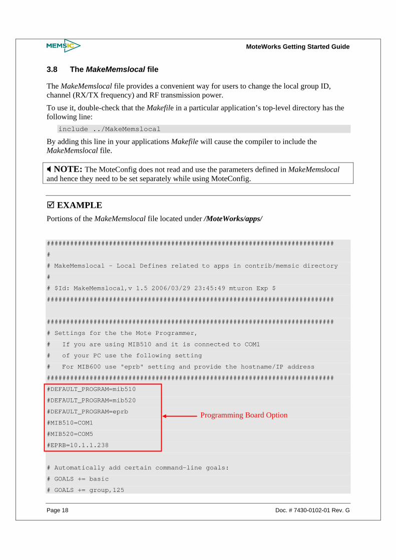
3.8 The MakeMemslocal file
The MakeMemslocal file provides a convenient way for users to change the local group ID, channel (RX/TX frequency) and RF transmission power.
To use it, double-check that the Makefile in a particular application’s top-level directory has the following line:
include ../MakeMemslocal
By adding this line in your applications Makefile will cause the compiler to include the MakeMemslocal file.
NOTE: The MoteConfig does not read and use the parameters defined in MakeMemslocal and hence they need to be set separately while using MoteConfig.
EXAMPLE
Portions of the MakeMemslocal file located under /MoteWorks/apps/
##########################################################################
#
# MakeMemslocal - Local Defines related to apps in contrib/memsic directory
#
# $Id: MakeMemslocal,v 1.5 2006/03/29 23:45:49 mturon Exp $
##########################################################################
##########################################################################
# Settings for the the Mote Programmer,
# If you are using MIB510 and it is connected to COM1
# of your PC use the following setting
# For MIB600 use "eprb" setting and provide the hostname/IP address
##########################################################################
#DEFAULT_PROGRAM=mib510
#DEFAULT_PROGRAM=mib520
#DEFAULT_PROGRAM=eprb
#MIB510=COM1
#MIB520=COM5
#EPRB=10.1.1.238
# Automatically add certain command-line goals:
# GOALS += basic
# GOALS += group,125
Programming Board Option

MoteWorks Getting Started Guide
Doc. # 7430-0102-01 Rev. G Page 19
# GOALS += freq,903
##########################################################################
# set Mote group id
# - default mote group
##########################################################################
#DEFAULT_LOCAL_GROUP=0x7D
##########################################################################
# set radio channel (freq)
# -Uncomment ONLY one line to choose the desired radio operating freq.
# -Select band based on freq label tag on mote (916,433..)
# (i.e. 433Mhz channel will not work for mote configured for 916Mhz)
##########################################################################
#
# 916 MHz Band
#
# CHANNEL_00 - 903 MHz CHANNEL_02 - 904 MHz CHANNEL_04 - 905 MHz
# CHANNEL_06 - 906 MHz CHANNEL_08 - 907 MHz CHANNEL_10 - 908 MHz
# CHANNEL_12 - 909 MHz CHANNEL_14 - 910 MHz CHANNEL_16 - 911 MHz
# CHANNEL_18 - 912 MHz CHANNEL_20 - 913 MHz CHANNEL_22 - 914 MHz
# CHANNEL_24 - 915 MHz CHANNEL_26 - 916 MHz CHANNEL_28 - 917 MHz
# CHANNEL_30 - 918 MHz CHANNEL_32 - 919 MHz CHANNEL_34 - 920 MHz
# CHANNEL_36 - 921 MHz CHANNEL_38 - 922 MHz CHANNEL_40 - 923 MHz
# CHANNEL_42 - 924 MHz CHANNEL_44 - 925 MHz CHANNEL_46 - 926 MHz
# CHANNEL_48 - 927 MHz
#
# Original Channels defined by TinyOS 1.1.0
# CHANNEL_100 - 914.077 MHz CHANNEL_102 - 915_988 MHz
#
#-----------------------------------------------------------------------
#RADIO_CLASS = 916
#-----------------------------------------------------------------------
#RADIO_CHANNEL = 00
#RADIO_CHANNEL = 02
#RADIO_CHANNEL = 04
……
……
……
#RADIO_CHANNEL = 102
Group ID Selection
RF Band Selection for MICA2
RF Channel Selection for MICA2

MoteWorks Getting Started Guide
Page 20 Doc. # 7430-0102-01 Rev. G
#--------------------------------------------------------------------------
#--------------------------------------------------------------------------
# 868 MHz Band
#
# CHANNEL_00 - 869 MHz CHANNEL_02 - 870 MHz
#
#
#--------------------------------------------------------------------------
#RADIO_CLASS = 868
#--------------------------------------------------------------------------
#RADIO_CHANNEL = 00
#RADIO_CHANNEL = 02
#--------------------------------------------------------------------------
#--------------------------------------------------------------------------
# 433 MHz Band
#
# CHANNEL_00 - 433.113 MHz CHANNEL_02 - 433.616 MHz
# CHANNEL_04 - 434.108 MHz CHANNEL_06 - 434.618 MHz
#
# Original Channels defined by TinyOS 1.1.0
# CHANNEL_100 - 433.002 MHz CHANNEL_102 - 434.845 MHz
#
#--------------------------------------------------------------------------
#RADIO_CLASS = 433
#--------------------------------------------------------------------------
#RADIO_CHANNEL = 00
#RADIO_CHANNEL = 02
#RADIO_CHANNEL = 04
#RADIO_CHANNEL = 06
#RADIO_CHANNEL = 100
#RADIO_CHANNEL = 102
#--------------------------------------------------------------------------
#--------------------------------------------------------------------------
# 315 MHz Band
#

MoteWorks Getting Started Guide
Doc. # 7430-0102-01 Rev. G Page 21
# CHANNEL_00 - 315 MHz
# Original Channels co-efficients defined by TinyOS 1.1.0
# CHANNEL_100 - 315.178 MHz
#--------------------------------------------------------------------------
#RADIO_CLASS = 315
#RADIO_CHANNEL = 00
#RADIO_CHANNEL = 100
#--------------------------------------------------------------------------
##########################################################################
# MICA2 and M9100 Family Radio Power
# - Radio transmit power is by a value (RTP) between 0x00 and 0xFF
# - RTP = 0 for least power; =0xFF for max transmit power
#-------------------------------------------------------------------------
# For Mica2 and Mica2Dot
# Freq Band: Output Power(dBm) RTP
# 916 Mhz -20 0x02
# -10 0x09
# 0 (1mw) 0x80
# 5 0xFF
# 433 Mhz -20 0x01
# -10 0x05
# 0 (1mw) 0x0F
# 10 0xFF
#
# Uncomment the line for the required Power Setting
##########################################################################
#RADIO_POWER=0xFF
#RADIO_POWER=0x0F
#RADIO_POWER=0x09
#RADIO_POWER=0x05
#RADIO_POWER=0x02
#RADIO_POWER=0x01
#########################################################
#
# Zigbee Channel Selection
# CHANNEL_11 - 2405 MHz CHANNEL_12 - 2410 MHz CHANNEL_13 - 2415 MHz
# CHANNEL_14 - 2420 MHz CHANNEL_15 - 2425 MHz CHANNEL_16 - 2430 MHz
# CHANNEL_17 - 2435 MHz CHANNEL_18 - 2440 MHz CHANNEL_19 - 2445 MHz
RF Power Selection for MICA2

MoteWorks Getting Started Guide
Page 22 Doc. # 7430-0102-01 Rev. G
# CHANNEL_20 - 2450 MHz CHANNEL_21 - 2455 MHz CHANNEL_22 - 2460 MHz
# CHANNEL_23 - 2465 MHz CHANNEL_24 - 2470 MHz CHANNEL_25 - 2475 MHz
# CHANNEL_26 - 2480 MHz
#
# 15, 20, 25 & 26 seem to be non-overlapping with 802.11
#########################################################
#RADIO_CHANNEL=11
#RADIO_CHANNEL=12
……
……
……
#RADIO_CHANNEL=24
#RADIO_CHANNEL=25
#RADIO_CHANNEL=26
##############################################
#
# MICAZ and M2100 RF Power Levels
#
#TXPOWER_MAX TXPOWER_0DBM
#TXPOWER_0DBM 0x1F //0dBm
#TXPOWER_M1DBM 0x1B //-1dBm
#TXPOWER_M3DBM 0x17 //-3dBm
#TXPOWER_M5DBM 0x13 //-5dBm
#TXPOWER_M7DBM 0x0F //-7dBm
#TXPOWER_M10DBM 0x0B //-10dBm
#TXPOWER_M15DBM 0x07 //-15dBm
#TXPOWER_M25DBM 0x03 //-25dBm
#TXPOWER_MIN TXPOWER_M25DBM
##########################################
#RADIO_POWER=TXPOWER_MAX
#RADIO_POWER=TXPOWER_M0DBM
#RADIO_POWER=TXPOWER_M3DBM
#RADIO_POWER=TXPOWER_M5DBM
#RADIO_POWER=TXPOWER_M10DBM
#RADIO_POWER=TXPOWER_M15DBM
#RADIO_POWER=TXPOWER_M25DBM
#RADIO_POWER=TXPOWER_MIN
RF Channel Selection
for MICAz and IRIS
RF Power Selection for MICAz

MoteWorks Getting Started Guide
Doc. # 7430-0102-01 Rev. G Page 23
# IRIS RF Power Levels
#
#TXPOWER_MAX TXPOWER_3_2DBM
#TXPOWER_3_2DBM 0 //3.2dBm
#TXPOWER_2_8DBM 1 //2.8dBm
#TXPOWER_2_3DBM 2 //2.3dBm
……
……
……
#TXPOWER_MIN TXPOWER_M17DBM
##########################################
#RADIO_POWER=TXPOWER_MAX
RADIO_POWER=TXPOWER_3_2DBM
#RADIO_POWER=TXPOWER_2_8DBM
#RADIO_POWER=TXPOWER_2_3DBM
……
……
……
#RADIO_POWER=TXPOWER_MIN
3.9 Radio Frequencies
The radio transceivers on the MICAz, MICA2, and MICA2DOT support multiple frequencies. Units are delivered at a pre-defined channel in 315 MHz, 433 MHz, 915 MHz, or 2.4 GHz ISM bands. All of the coefficients for radio tuning for the MICA2 and MICA2DOT are contained in the TinyOS file CC1000Const.h located in /MoteWorks/tos/platform/mica2/.
Users must compile in the correct base radio frequency to prevent radio communication failure. The best and safest way to make sure you’re compiling for the correct frequency for any Mote platform is to edit the MakeMemslocal file (described in Section 3.8 above).
3.10 Automated Build Tools MoteWorks offers several automated tools to simplify the compilation process.
3.10.1 build This command is similar to make, but filters out the compile output to highlight only error messages and warnings.
$ build micaz
RF Power Selection for IRIS

MoteWorks Getting Started Guide
Page 24 Doc. # 7430-0102-01 Rev. G
compiling Blink to a micaz binary compiled Blink to build/micaz/main.exe 1546 bytes in ROM 99 bytes in RAM
3.10.2 Buildall This command performs an automated build of all applications under that application folder. $ buildall -?
$Id: buildall,v 1.8 2006/02/11 02:11:57 mturon Exp $ Usage: buildall [OPTION]...
--cvs Updates latest source code from cvs. --docs Runs nesdoc in addition to normal build. --summary Shows running summary.
3.11 Mote Programming Tools MoteWorks also offers several automated tools to simplify the Mote programming process.
3.11.1 flash This command flashes an image onto the Mote. The image filename must be specified in the first argument. The Node ID and COM port arguments are optional, and default to node id 1 and COM1. It only works with MIB510 and MIB520 programming interface boards.
$ flash Usage: flash [image] [nodeid] [port] $ flash main.exe 1 /dev/ttyS0 FLASH main.exe as node 1 to /dev/ttyS0 avr-objcopy --output-target=srec build build avr-objcopy: build: File format not recognized set-mote-id build build-1 1
uisp -dprog=mib510 -dpart=ATmega128 -dserial=/dev/ttyS0 --wr_fuse_h=0xd9 --wr_fu se_e=ff --erase --upload if=build-1
3.11.2 flashall This command flashes an image onto a test bed of Motes. It works with MIB510, MIB520, or MIB600 interface boards.
$ flashall Usage: flashall image_file < port_list Description: Will flash [image_file] to all ports passed in [port_list] file. [port_list] is a text file where each line is one of: /dev/tty# or /dev/ttyS#, or ip ###.###.###.### First line will be assigned node id == 0. All remaining lines will be assigned node id == ###.
3.11.3 fuses This command allows the user to read or write the fuse settings of the Mote on the programming interface board.
$ fuses
fuses Ver:$Id: fuses,v 1.1 2005/03/01 17:24:19 jprabhu Exp $

MoteWorks Getting Started Guide
Doc. # 7430-0102-01 Rev. G Page 25
Usage: fuses [command] [port] [args]
read = read fuses
clkint = set to internal oscillator
clkext = set to external oscillator
jtagen = enable JTAG
jtagdis = disable JTAG
Command Flag
------- ------------------------------------------------------------
clkext --wr_fuse_l=0xff
clkint --wr_fuse_l=0xc4
jtagdis --wr_fuse_h=0xd9
jtagen --wr_fuse_h=0x19
read --rd_fuses
3.11.4 motelist This command lists MIB520 and Telos devices attached to the USB port.
3.12 TinyOS Interoperability and Tree Management Users can interoperate between the prior versions of TinyOS (such as 1.1.10) and MoteWorks. Several commands are provided to conveniently switch back and forth between TinyOS and MoteWorks trees.
3.12.1 gettos This command allows the user to see how their current TinyOS environment is configured.
$ gettos
TOSDIR=/opt/MoteWorks/tos
TOSROOT=/opt/MoteWorks
MAKERULES=/opt/MoteWorks/make/Makerules
total 1
drwx------+ 2 mturon 0 Feb 3 13:15 CVS
-rwx------+ 1 mturon 77 Feb 3 13:15 README.txt
drwx------+ 9 mturon 0 Jan 27 08:45 apps
drwxr-xr-x+ 3 mturon 0 Feb 8 12:14 doc
drwx------+ 8 mturon 0 Feb 3 15:51 make
drwx------+ 12 mturon 0 Feb 14 17:34 tools
drwx------+ 10 mturon 0 Jan 12 01:21 tos
3.12.2 settos The user can switch to a new MoteWorks tree by changing the symbolic link. Both trees maintain the same /opt/MoteWorks root, but the users can maintain two versions, the 2.0 Standard release and a 2.1 Enterprise developer tree for example. The first time you run this command, it will rename your current MoteWorks tree to the specified version.

MoteWorks Getting Started Guide
Page 26 Doc. # 7430-0102-01 Rev. G
$ settos 2.0 Warning: /opt/MoteWorks directory moved to /opt/MoteWorks.2.0 Warning: /opt/MoteWorks will be made into a symbolic link Set TinyOS tree to: /opt/MoteWorks.2.0
$ settos 2.1 Set TinyOS tree to: /opt/MoteWorks.2.1
3.12.3 usetos This command allows the users to switch between MoteWorks and a legacy TinyOS 1.x environment.
usetos - switch to MoteWorks usetos tinyos - switch to TinyOS 1.x usetos tinyos-2.x - switch to TinyOS 2.x
The following command shell session shows switching to a TinyOS 2.x environment, and back into MoteWorks.
$ `usetos tinyos-2.x` $ gettos TOSDIR=/opt/tinyos-2.x/tos TOSROOT=/opt/tinyos-2.x MAKERULES=/opt/tinyos-2.x/support/make/Makerules total 5 drwx------+ 2 mturon 0 Feb 16 23:50 CVS -rwx------+ 1 mturon 156 Feb 16 23:49 README drwx------+ 12 mturon 0 Feb 16 23:50 apps drwx------+ 7 mturon 0 Feb 16 23:49 doc -rwx------+ 1 mturon 2635 Mar 9 2005 overall-todo.txt drwx------+ 5 mturon 0 Jan 20 12:13 support drwx------+ 6 mturon 0 Feb 16 23:50 tools drwx------+ 11 mturon 0 Feb 16 23:50 tos $ `usetos` $ gettos TOSDIR=/opt/MoteWorks/tos TOSROOT=/opt/MoteWorks MAKERULES=/opt/MoteWorks/make/Makerules lrwxrwxrwx 1 mturon 18 Feb 17 17:52 /opt/MoteWorks -> /opt/MoteWorks.2.1
3.13 Compiling Utilities MoteWorks offers several compilation utilities.
3.13.1 make This command allows users to compile their nesC code with several options directly from the command line (such as XMesh power mode, group ID, radio frequency). make <platform>
<route,hp|lp|elp> <group,125>
<freq,315|433|433.5|434|434.5|903|904|926|2405|2420|2445>

MoteWorks Getting Started Guide
Doc. # 7430-0102-01 Rev. G Page 27
3.13.2 mote-mem This utility displays memory usage of compiled firmware by module. Usage is broken down by Program ROM, Constants RAM, and Heap RAM.
$ mote-mem build/micaz/main.exe Module Memory Usage: AVR binary file "build/micaz/main.exe" 1542 bytes of Program ROM allocated 1340 bytes of Program ROM used 202 bytes of Program ROM wasted usage by module: 164 HPLPowerManagementM 62 TOS_post 518 TimerM 4 __nesc_atomic_end 8 __nesc_atomic_start 176 __vector_15 408 main 4 bytes of Constants RAM allocated 4 bytes of Constants RAM used 0 bytes of Constants RAM wasted usage by module: 1 HPLPowerManagementM 1 TOS_DATA_LENGTH 1 TOS_PLATFORM 1 TOS_ROUTE_PROTOCOL 95 bytes of Heap RAM allocated 95 bytes of Heap RAM used 0 bytes of Heap RAM wasted usage by module: 4 HPLClock 1 LedsC 1 PotM 64 TOSH_queue 1 TOSH_sched_free 1 TOSH_sched_full 1 TOS_BASE_STATION 22 TimerM
3.13.3 treediff This utility displays source differences between two different applications.
3.14 XSniffer XSniffer is a Memsic-developed tool that allows users to monitor multi-hop communication over XMesh. This program runs on a PC and uses a MICA2 or MICAz Mote to monitor the RF packet traffic. The following applications are required to run XSniffer:
1. XSniffer TinyOS code: This code can be built for either a MICA2 or MICAz running on a Memsic MIB510 or MIB520 base station. The source code is located under
/MoteWorks/apps/general/XSniffer 2. XSniffer GUI which installs and runs on the PC. The executables are installed in C:/
Memsic/XSniffer.

MoteWorks Getting Started Guide
Page 28 Doc. # 7430-0102-01 Rev. G
NOTE: XSniffer is set for a group ID=0 and TOS_LOCAL_ADDRESS = 0xff00 so that it will never return an acknowledgement for any radio packet meant for another mote.
3.14.1 Building and Starting XSniffer In the /MoteWorks/apps/general directory, build and install the application for the correct platform. For a MICAz and a MIB510 the command would be make install micaz mib510,/dev/ttyS0
WARNING: XSniffer does not run XMesh. Do not use route,hp2 or route,lp2 variables when building. XSniffer uses TOSH_DATA_LENGTH = 64 which should accommodate the largest user data packets.
Open the XSniffer GUI, select the correct COM port and START. Network messages should appear in the Log tab.
3.14.2 Using XSniffer XSniffer can be used to monitor the behavior of the mesh. It will display all radio messages overheard within its radio range. Use XSniffer to:
Check to see if a mote has joined the mesh. When this happens the health and data packets will change from a broadcast address to either the base station address or the address of another parent.
Monitor the packet sequence numbers of individual mote radio packets. Monitor downstream radio communication from the base station. Monitor radio message retries. Monitor route update and time synchronization messages.
For more details on XSniffer, refer to XMesh User’s manual.

MoteWorks Getting Started Guide
Doc. # 7430-0102-01 Rev. G Page 29
4 Introduction to TinyOS and nesC
In this chapter you will be introduced to:
Introduction to TinyOS and programming philosophy Introduction to nesC language
4.1 TinyOS TinyOS is an open-source operating system designed for wireless embedded sensor networks. It features a component-based architecture, which enables rapid innovation and implementation while minimizing code size as required by the severe memory constraints inherent in sensor networks. TinyOS’s component library includes network protocols, distributed services, sensor drivers, and data acquisition tools—all of which can be used as-is or be further refined for a custom application. TinyOS’s event-driven execution model enables fine-grained power management yet allows the scheduling flexibility made necessary by the unpredictable nature of wireless communication and physical world interfaces.
TinyOS is not an operating system (“OS”) in the traditional sense; it is a programming framework for embedded systems and set of components that enable building an application-specific OS into each application. The reason for this is to ensure that the application code has an extremely small memory foot print. In addition TinyOS is designed to have no file system, supports only static memory allocation, implement a simple task model, and provide minimal device and networking abstractions.
TinyOS has a component-based programming model (codified by the nesC language). Like other operating systems, TinyOS organizes its software components into layers. The lower the layer the closer it is to the hardware; the higher the component, the closer it is to the application. A complete TinyOS application is a graph of components, each of which is an independent computational entity.
Components have three computational concepts: 1) commands, 2) events, and 3) tasks. Commands and events are mechanisms for inter-component communication, while tasks are used to express intra-component concurrency. A command is typically a request to a component to perform a service. A typical example is starting a sensor reading. By comparison, an event would signal the completion of that service. Events may also be signaled asynchronously, for example, due to hardware interrupts or message arrival. From a traditional OS perspective, commands are analogous to downcalls and events to call backs. Commands and events cannot block. However, a request for a service is split-phase in that the request for service (the command) and the completion signal (the corresponding event) are decoupled. The command returns immediately and the event signals completion at a later time.
Rather than performing a computation immediately, commands and event handlers may post a task, a function executed by the TinyOS scheduler at a later time. This allows commands and events to be responsive, returning immediately while deferring extensive computation to tasks. While tasks may perform significant computation, their basic execution model is run-to-completion, rather than to run indefinitely; this allows tasks to be much lighter-weight than threads. Tasks represent internal concurrency within a component and may only access state information within that component. The TinyOS scheduler uses a non-preemptive, first in, first out (“FIFO”) scheduling policy.

MoteWorks Getting Started Guide
Page 30 Doc. # 7430-0102-01 Rev. G
A developer composes an application by writing components and wiring them to other TinyOS components that provide implementations of the required services. How developers write components and wire them in nesC is discussed later in this document.
4.1.1 TinyOS Programming philosophy The TinyOS operating system, libraries, and applications are all written in nesC, a new structured component-based language. The nesC language is primarily intended for embedded systems such as sensor networks. The nesC has a C-like syntax, but supports the TinyOS concurrency model, as well as mechanisms for structuring, naming, and linking together software components into robust network embedded systems. The principal goal is to allow application designers to build components that can be easily composed into complete, concurrent systems, and yet perform extensive checking at compile time.
TinyOS also defines a number of important concepts that are expressed in nesC. A brief summary is provided here.
Table 4-1. Description of the Main TinyOS/nesC Concepts
TinyOS/nesC Concept Description
Application A TinyOS/nesC application consists of one or more components, linked (“wired”) together to form a run-time executable
Component Components are the basic building blocks for nesC applications. There are two types of components: modules and configurations. A TinyOS component can provide and use interfaces.
Module A component that implements one or more interfaces.
Configuration
A component that wires other components together, connecting interfaces used by components to interfaces provided by others. (This is called wiring.) The idea is that a developer can build an application as a set of modules, wiring together those modules by providing a configuration. Furthermore, every nesC application is described by a top-level configuration that specifies the components in the application and how they invoke one another.
Interface
An interface is used to provide an abstract definition of the interaction of two components. This concept is similar to Java in that an interface should not contain code or wiring. It simply declares a set of functions that the interface’s provider must implement—commands—and another set of functions the interfaces’ requirer must implement—events. In this way it is different than Java interfaces which specify one direction of call. NesC interfaces are bi-directional. For a component to call the commands in an interface it must implement the events of that interface. A single component may require or provide multiple interfaces and multiple instances of the same interface. These interfaces are the only point of access to the component.
The nesC also defines a concurrency model, based on tasks and hardware event handlers, and detects data races at compile time. When looking at the files in an application directory, you can identify the nesC files because it uses the extension “.nc” for all source files—interfaces, modules, and configurations.
4.1.2 Concurrency Model TinyOS executes only one program consisting of selected system components and custom components needed for a single application. There are two threads of execution: tasks and hardware event handlers. Tasks are functions whose execution is deferred. Once scheduled, they run to completion and do not preempt one another. Hardware event handlers are executed in response to a hardware interrupt and also run to completion. Unlike a task, it may preempt the

MoteWorks Getting Started Guide
Doc. # 7430-0102-01 Rev. G Page 31
execution of a task or other hardware event handler. Commands and events that are executed as part of a hardware event handler must be declared with the async keyword.
Because tasks and hardware event handlers may be preempted by other asynchronous code, nesC programs are susceptible to certain race conditions. Races are avoided either by accessing shared data exclusively within tasks, or by having all accesses within atomic statements. The nesC compiler reports potential data races to the programmer at compile-time. It is possible the compiler may report a false positive. In this case a variable can be declared with the norace keyword. The norace keyword should be used with extreme caution.
NesC programming has concepts and keywords which are similar to other languages, notably the C programming language and to some degree Java. This chapter will introduce the underlying concepts and the keywords used to implement those concepts
4.2 The nesC Language The nesC (network embedded systems C) is an extension to C designed to embody the structuring concepts and execution model of TinyOS. The basic concepts behind nesC are:
4.2.1 Separation of construction and composition Programs are built out of components, which are assembled (“wired”) to form whole programs. Components define two scopes, one for their specification (containing the names of their interface instances) and one for their implementation. Components have internal concurrency in the form of tasks. Threads of control may pass into a component through its interfaces. These threads are rooted either in a task or a hardware interrupt.
4.2.2 Specification of component behavior in terms of set of interfaces Interfaces may be provided or used by the component. The provided interfaces are intended to represent the functionality that the component provides to its user, the used interfaces represent the functionality the component needs to perform its job.
4.2.3 Interfaces are bidirectional Interfaces specify a set of functions to be implemented by the interface’s provider (commands) and a set to be implemented by the interface’s user (events). This allows a single interface to represent a complex interaction between components (e.g. registration of interest in some event, followed by a callback when that event happens). This is critical because all lengthy commands in TinyOS (e.g. send packet) are non-blocking; their completion is signaled through an event (send done). By specifying interfaces, a component cannot call the send command unless it provides an implementation of the sendDone event. Typically commands call downwards, i.e., from application components to those closer to the hardware, while events call upwards. Certain primitive events are bound to hardware interrupts (the nature of this binding is system-dependent, so is not described further in this reference manual)
4.2.4 Components are statically linked to each other via their interfaces This increases runtime efficiency, encourages robust design, and allows for better static analysis of programs.

MoteWorks Getting Started Guide
Page 32 Doc. # 7430-0102-01 Rev. G
4.2.5 Use of whole-program compilers NesC is designed under the expectation that code will be generated by whole-program compilers. This allows for better code generation and analysis. An example of this is nesC’s compile-time data race detector.
4.2.6 Tasks and interrupt handlers The concurrency model of nesC is based on run-to-completion tasks, and interrupt handlers which may interrupt tasks and each other. The nesC compiler signals the potential data races caused by the interrupt handlers.
For more details on TinyOS and nesC programming concepts, refer to the “TinyOS/nesC Reference Manual” by Phil Levis included on the MoteWorks CD.

MoteWorks Getting Started Guide
Doc. # 7430-0102-01 Rev. G Page 33
5 First Steps in nesC Programming
In this chapter you will learn:
The basics of nesC and TinyOS programming How to use the Timer and LED components How to compile and download an application to a Mote
This first application is called MyApp. As the name suggests it uses one of the timers on the ATmega128L Mote. The timer will be set to fire continuously every second and the Mote red LED will toggle on and off to show this visually. So why go through the trouble of this program? To help the developer unfamiliar with TinyOS, nesC & Motes gain more confidence in embedded programming concepts before tackling more complex applications.
The steps that you’ll take to build the application will be as follows:
Enter in all necessary code and auxiliary files Build (compile) and download the application Take a closer look at the code and auxiliary files
5.1 Hardware Requirements This chapter requires the following hardware:
One Mote: standard editions of MICA2 (MPR4x0), MICAz (MPR2400), IRIS (XM2110) or OEM editions MPR600, MPR2600, M2110.
One gateway / programming board: MIB510, MIB520, or MIB600 and the associated hardware (cables, power supply) for each
A Windows PC with MoteWorks installed
5.2 A simple nesC program: MyApp To get started the first thing to do is to create the application folder (directory) where all your application code and other files will be stored.
1. Change into the directory /MoteWorks/apps/tutorials/ and create a new subfolder (subdirectory) that should have the name as your application is to be called. In this first lesson the application will be called MyApp.
2. You have two options to create the source files. You can copy, paste, and rename the subdirectory /lesson_1 found in the /tutorials subdirectory and avoid some typing. If you choose to do this you can go straight to the compiling and installation step or follow these instructions and learn along the way.
Within the MoteWorks framework a minimum of five files will be in any application’s directory:
1. Makefile (section 5.2.1)
2. Makefile.component (section 5.2.2)
3. Application’s configuration written in nesC

MoteWorks Getting Started Guide
Page 34 Doc. # 7430-0102-01 Rev. G
4. Application’s module written in nesC
5. README (optional)
The Makefile and Makefile.component are created next.
5.2.1 Makefile
The first step in creating an application is to type in the Makefile. Alternatively you can copy and paste this file from the subdirectory /lesson_1 into /MyApp (both of which are in the /tutorials subdirectory).
To create the Makefile, enter the following text into a new document in Programmer’s Notepad:
include Makefile.component include $(TOSROOT)/apps/MakeMemslocal include $(MAKERULES)
When finished save the file with File > Save As… using the following parameters:
File name Makefile
Save as type All files (“.”)
File format No change to file format
5.2.2 Makefile.component
The next step is to create the Makefile.component file. This file describes the top level application component, MyApp and the name of the sensorboard we are going to use. The sensorboard reference tells the compiler we want to use the pre-built nesC components for accessing the sensor devices on that board. Each sensorboard has its own set of pre-built nesC sensor components, also referred to as drivers.
To create the Makefile.component file, enter the following text into a new document in Programmer’s Notepad:
COMPONENT=MyApp SENSORBOARD=mts310
When finished save the file with File > Save As… using the following parameters:
File name Makefile.component
Save as type All files (“.”)
File format No change to file format
5.2.3 Create the Top-Level Configuration
The application’s configuration is located in the MyApp.nc file. The StdControl interface must always be implemented as the bare minimum for an application. The StdControl interface provides the basic functionality for the TinyOS application to be initialized, started and stopped.

MoteWorks Getting Started Guide
Doc. # 7430-0102-01 Rev. G Page 35
To create the application’s configuration, enter the following text into a new document in Programmer’s Notepad:
/** * This configuration shows how to use the Timer and LED components **/ configuration MyApp { } implementation { components Main, MyAppM, TimerC, LedsC; Main.StdControl -> TimerC.StdControl; Main.StdControl -> MyAppM.StdControl; MyAppM.Timer -> TimerC.Timer[unique("Timer")]; MyAppM.Leds -> LedsC.Leds; }
The last two lines in the configuration wire the TimerC and LedsC components to the application’s module. The module can then control the Timer and LED devices by calling functions in the TimerC and LedsC components. The concept of component wiring will be fully explained in a later chapter dedicated to NesC/ TinyOS programming concepts. When finished save the file with File > Save As… using the following parameters:
File name MyApp.nc
Save as type All files (“.”)
File format No change to file format
NOTE: When you do save or save as and use the “.nc” file extension, Programmers Notepad will use the default text coloring and highlighting scheme.
5.2.4 Create the Module
The application’s module is located in the MyAppM.nc file. The module file is where the application programming code is entered. This is where we type in programming code to start the Timer and toggle the red LED on the Mote.
To create the application’s module, enter the following text into a new document using Programmer’s Notepad:
/** * This module shows how to use the Timer and LED components **/ module MyAppM { provides { interface StdControl; } uses { interface Timer; interface Leds; } }

MoteWorks Getting Started Guide
Page 36 Doc. # 7430-0102-01 Rev. G
implementation { /** * Initialize the components. * * @return Always returns <code>SUCCESS</code> **/ command result_t StdControl.init() { call Leds.init(); return SUCCESS; } /** * Start things up. This just sets the rate for the clock * component. * * @return Always returns <code>SUCCESS</code> **/ command result_t StdControl.start() { // Start a repeating timer that fires every 1000ms return call Timer.start(TIMER_REPEAT, 1000); } /** * Halt execution of the application. * This just disables the clock component. * * @return Always returns <code>SUCCESS</code> **/ command result_t StdControl.stop() { return call Timer.stop(); } /** * Toggle the red LED in response to the <code>Timer.fired</code> * event. * * @return Always returns <code>SUCCESS</code> **/ event result_t Timer.fired() { call Leds.redToggle(); return SUCCESS; } }
When finished save the file with File > Save As… using the following parameters:
File name MyAppM.nc
Save as type All files (“.”)
File format No change to file format

MoteWorks Getting Started Guide
Doc. # 7430-0102-01 Rev. G Page 37
5.2.5 Compile and Install the Code in a Mote
Now that you have edited all the application files or copied over from the /lesson_1 folder, we can proceed with the compilation and installation steps.
NOTE: You need to be in the .nc of the app file you want to compile and program before you can execute shell commands from Programmer’s Notepad.
You can compile your nesC application code from Programmer’s Notepad.
To compile your application:
• Select Tools > make mica2 (or make micaz or make mica2dot)
• The “Output” section of the Programmers Notepad will print the compiling results to the screen:
• After the compilation has completed you should see “writing TOS image” as the last line in the Output window. If you don’t see this then you have made an error typing in one of your files. Verify your files against the files provided for you in the /lesson_1 folder. Copy them over from the /lesson_1 folder into your folder if you get stuck. Make sure you have success compiling your application before proceeding.
You can also install your application to a Mote plugged into your programming board using Programmer’s Notepad. To install your application:
• Select Tools > shell. When prompted for parameters, type in make mica2 reinstall mib510,com1 (or make micaz reinstall or make mica2dot reinstall)

MoteWorks Getting Started Guide
Page 38 Doc. # 7430-0102-01 Rev. G
NOTE: This example assumes you are using an MIB510 programming board connected to your PC using the COM1 serial port. Please make the necessary adjustments if using a different programming board and/or serial port.
• The “Output” section of the Programmers Notepad will print the installation results to the screen:
• Make sure you see the “Uploading: flash” line complete without errors. You should then
see the red LED on the Mote blinking on and off every second.
Congratulations, you have just written, compiled and installed your first TinyOS embedded application using MoteWorks!
5.3 A Closer Look at MyApp The reason for the distinction between modules and configurations is to allow a developer to quickly "snap together" applications using pre-build components without additional programming. For example, a developer could provide a configuration that simply wires together one or more pre-existing modules. The idea is for developers to provide a set of “library” components that can be re-used in a wide range of applications.
5.3.1 Makefile and Makefile.component
What are the Makefile and Makefile.component? Why do I need to use them? The Makefile is a file containing the dependencies (other files) your application uses during the compilation step. Within MoteWorks all Makefiles within a particular application subdirectory (/xmesh, /xsensor, /examples, /general, /tutorials) have the same contents. The Makefile.component is simply a

MoteWorks Getting Started Guide
Doc. # 7430-0102-01 Rev. G Page 39
MoteWorks convention to describe the particular dependencies for a particular application. The Makefile.component is included into the Makefile at build time.
5.3.2 Comments
Comments make your code more readable. They help explain your code to others, and can be a reminder to yourself when you need to modify the code. nesC programming supports the following type of comments. If you use Programmers Notepad to edit nesC code, you’ll find that these comments are highlighted in green text. /* text */
The compiler ignores everything from the opening /* to the closing */. /** documentation */
This style indicates a documentation comment that is used by automatic documentation utilities such as GraphViz. As with the first kind of comment, the compiler ignores all the text in the comment. // text
The compiler ignore everything from the // to the end of the line.
The green parts in the following code are comments:
configuration MyApp { // This configuration provides no interfaces } implementation { components Main, My App_TimerM, TimerC; Main.StdControl -> MyAppM.StdControl; Main.StdControl -> MyAppC.StdControl; MyApp.Timer -> TimerC.Timer[unique("Timer")]; }
5.3.3 Defining an Application’s Configuration
The nesC compiler, ncc, compiles an application when given the file containing the top-level configuration. The Makefile in the applications directory invokes nesC with appropriate options or dependencies on the application’s top-level configuration.
All applications require a top-level configuration file, which is typically named after the application itself. In this case MyApp.nc is the configuration for the MyApp application and the source file that the nesC compiler uses to generate an executable file. On the other hand MyAppM.nc actually provides the functionality of the MyApp application. As you might guess, MyApp.nc is used to wire the MyAppM.nc module to other components that are required by the MyApp application.
Let’s examine the initial lines of the MyApp application. The first thing to notice is the key word configuration (in boldface) which indicates that this is a nesC configuration (as opposed to a nesC module)
configuration MyApp {

MoteWorks Getting Started Guide
Page 40 Doc. # 7430-0102-01 Rev. G
// this module does not provide any interface } implementation { …
These lines simply state that the name of the configuration is called MyApp. A configuration is one of two types of components defined by nesC. The general form for a configuration is shown in the code example below.
configuration ComponentName { //Configuration definition block which may or may not have //interfaces. }
The interfaces that are used or provided are enclosed by the braces that begin and end the configuration definition block.
NOTE: Since the MyApp configuration doesn’t provide or use any interfaces, there is no text (other than perhaps a comment).
As the name suggestions a configuration is an assembly of other components that are connected together using a symbolic syntax that defines how components are related to one another. This is commonly called component wiring where one component is wired to another.
Let’s take a look at the lines below the configuration code block.
… implementation { components Main, MyApp; Main.StdControl -> MyAppM.StdControl; }
The next keyword to note is implementation. As implied the code block defined by implementation defines the wiring of components. The “connecting points” for the wiring is defined by a component’s interface, which will be discussed in more detail later. Following the keyword component is a list of nesC components that are referenced by the configuration. In this example the components are Main and MyAppM.
The line
Main.StdControl -> MyAppM.StdControl;
wires the StdControl interface in Main to the StdControl interface in MyAppM. MyAppM.StdControl.init() will be called by Main.StdControl.init(). The same rule applies to the start() and stop() commands.
Concerning used interfaces, it is important to note that subcomponent initialization functions must be explicitly called by the using component. For example, the MyAppM module uses the interface Leds, so Leds.init() is called explicitly in MyAppM.init().

MoteWorks Getting Started Guide
Doc. # 7430-0102-01 Rev. G Page 41
The nesC uses arrows to determine relationships between interfaces. Think of the right arrow “->” as “binds to”. The left side of the arrow binds an interface to an implementation on the right side. In other words, the component that uses an interface is on the left, and the component provides the interface is on the right.
The line
MyAppM.Timer -> TimerC.Timer[unique("Timer")];
is used to wire the Timer interface used by MyAppM to the Timer interface provided by TimerC. MyAppM.Timer on the left side of the arrow is referring to the interface called Timer (/MoteWorks/tos/interfaces/Timer.nc), while TimerC.Timer on the right side of the arrow is referring to the implementation of Timer. Remember that the arrow always binds interfaces (on the left) to implementations (on the right). The unique(“Timer”) statement makes certain we are using a timer instance not used anywhere else in the application – more on that later.
nesC supports multiple implementations of the same interface. The Timer interface is such an example. The TimerC implements multiple timers using timer id as a parameter.
Wirings can also be implied. For example, MyAppM.Leds -> LedsC;
is really shorthand for MyAppM.Leds -> LedsC.Leds;
In this example, the interface named Leds was not explicitly listed. Since no interface name is given on the right side of the arrow, the nesC compiler by default tries to bind to the same interface as on the left side of the arrow.
5.3.4 The component main: The scheduler
Conceptually a TinyOS application is a collection of components and a scheduler called Main. The components typically provide some computation or function and the scheduler runs the tasks created by those components. The code for Main is shown below.
configuration Main { uses interface StdControl; } implementation { components RealMain, PotC, HPLInit; StdControl = RealMain.StdControl; RealMain.hardwareInit -> HPLInit; RealMain.Pot -> PotC; }
Main is a component that is executed first in a TinyOS application. To be precise, the Main.StdControl.init() command is the first command executed in TinyOS followed by Main.StdControl.start(). Therefore, a TinyOS application must have the Main

MoteWorks Getting Started Guide
Page 42 Doc. # 7430-0102-01 Rev. G
component in its configuration. StdControl is a common interface used to initialize and start TinyOS components.
5.3.5 The MyAppM module
In the minimum case, an applications module looks something like this:
module ModuleName { provides { interface StdControl; } } implementation { command result_t StdControl.init() { return SUCCESS; } command result_t StdControl.start() { return SUCCESS; } command result_t StdControl.stop() { return SUCCESS; } }
While this module is not very useful, we’ll use it for instructional purposes. Let’s have a look at the StdControl interface (in /MotwWorks/tos/interfaces/StdControl.nc) before going back to discussing the rest of the application, as it is a very common interface in nesC programming.
interface StdControl { command result_t init(); command result_t start(); command result_t stop(); }
We see that StdControl defines three commands: init(),start(), and stop(). init() is called when a component is first initialized, and start() when it is started, that is, actually executed for the first time. stop() is called when the component is stopped, for example, in order to power off the device that it is controlling. init() can be called multiple times but will never be called after either start() or stop() are called. Specifically, the valid call patterns of StdControl are init*(start | stop)*. All three of these commands have “deep” semantics; calling init() on a component must make it call init() on all of its subcomponents.
Now let’s look further into the module MyAppM.nc. In many nesC applications, it is common to call a function periodically. The realization of that function is done by means of a timer. The name for the interface for a timer is, conveniently enough Timer.
** * Implementation for MyApp application. This is * just a shell of an application that wires in the Timer * module. **/
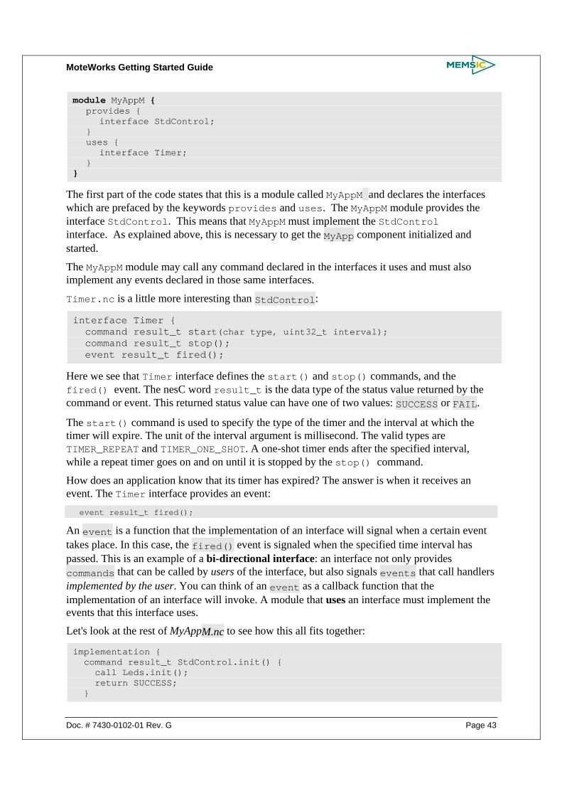
MoteWorks Getting Started Guide
Doc. # 7430-0102-01 Rev. G Page 43
module MyAppM { provides { interface StdControl; } uses { interface Timer; } }
The first part of the code states that this is a module called MyAppM and declares the interfaces which are prefaced by the keywords provides and uses. The MyAppM module provides the interface StdControl. This means that MyAppM must implement the StdControl interface. As explained above, this is necessary to get the MyApp component initialized and started.
The MyAppM module may call any command declared in the interfaces it uses and must also implement any events declared in those same interfaces.
Timer.nc is a little more interesting than StdControl:
interface Timer { command result_t start(char type, uint32_t interval); command result_t stop(); event result_t fired();
Here we see that Timer interface defines the start() and stop() commands, and the fired() event. The nesC word result_t is the data type of the status value returned by the command or event. This returned status value can have one of two values: SUCCESS or FAIL.
The start() command is used to specify the type of the timer and the interval at which the timer will expire. The unit of the interval argument is millisecond. The valid types are TIMER_REPEAT and TIMER_ONE_SHOT. A one-shot timer ends after the specified interval, while a repeat timer goes on and on until it is stopped by the stop() command.
How does an application know that its timer has expired? The answer is when it receives an event. The Timer interface provides an event: event result_t fired();
An event is a function that the implementation of an interface will signal when a certain event takes place. In this case, the fired() event is signaled when the specified time interval has passed. This is an example of a bi-directional interface: an interface not only provides commands that can be called by users of the interface, but also signals events that call handlers implemented by the user. You can think of an event as a callback function that the implementation of an interface will invoke. A module that uses an interface must implement the events that this interface uses.
Let's look at the rest of MyAppM.nc to see how this all fits together:
implementation { command result_t StdControl.init() { call Leds.init(); return SUCCESS; }

MoteWorks Getting Started Guide
Page 44 Doc. # 7430-0102-01 Rev. G
command result_t StdControl.start() { return call Timer.start(TIMER_REPEAT, 1000) ; } command result_t StdControl.stop() { return call Timer.stop(); } event result_t Timer.fired() { call Leds.redToggle(); return SUCCESS; } }
This is simple enough. As we see the MyAppM module implements the StdControl.init(), StdControl.start(), and StdControl.stop() commands, since it provides the StdControl interface. It also implements the Timer.fired() event, which is necessary since MyAppM must implement any event from an interface it uses.
The init() command in the implemented StdControl interface simply initializes the Leds subcomponent with the call to Leds.init(). The start() command invokes Timer.start() to create a repeat timer that expires every 1000 ms. stop() terminates the timer. Each time Timer.fired() event is triggered, the Leds.redToggle() toggles the red LED.
5.4 Generating the Component Structure Documentation
You can view a graphical representation of the component relationships within an application. TinyOS source files include metadata within comment blocks that ncc—the nesC compiler—uses to automatically generate html-formatted documentation.
To generate the documentation, use the following command:
make <platform> docs
The resulting documentation will have the filename generated in the file /MoteWorks/doc/nesdoc/<platform>.docs/nesdoc/<platform>/index.html. This is the main index to all documented applications.
The directory index takes you to an html file that looks like the diagram shown below.
Apps Components Interfaces All Files Source Tree source: apps.tutorials.lesson_1.MyApp.nc
Component: MyApp This configuration shows how to use the Timer and LED components

MoteWorks Getting Started Guide
Doc. # 7430-0102-01 Rev. G Page 45
Author:Memsic Inc.
Component Graph (text version, help)
Apps Components Interfaces All Files Source Tree

MoteWorks Getting Started Guide
Page 46 Doc. # 7430-0102-01 Rev. G
6 A Simple Sensing Application
In this chapter you will learn:
• How to create a simple Mote firmware application that reads light sensor data from your sensor board
• How to send a message containing the sensor data through the Mote serial port connected directly to the programming board
• How to send a message containing the sensor data over the Mote radio (single-hop network) to another Mote plugged into the programming board
• Using XServe to parse packets on a PC
• Using XSniffer to display the sensor data message on a PC.
6.1 Hardware Requirements This chapter requires the following hardware:
• Two Motes: standard editions of MICA2 (MPR4x0), MICAz (MPR2400), IRIS (XM2110) or OEM editions MPR600, MPR2600, M2110
• One sensor or data acquisition board: MDA100, MTS300 or MTS310
• One gateway board: MIB510, MIB520, or MIB600 and the associated hardware (cables, power supply) for each
• A Windows PC with MoteWorks installed
6.2 A Simple Sensing Application: MyApp A simple sensing application that samples the light sensor on a sensor board, packetizes, and sends the data back to the base station is presented here to help further familiarize you with nesC programming and TinyOS messaging.
The following enhancements will be made to the simple Timer application presented in Chapter 5:
• Take light readings using one of the following sensors boards: MTS300/310 or MDA100
• Use the Mote serial port (UART) and radio to send sensor data to the base station
• Blink the yellow LED when the sensor is sampled
• Blink the green LED when the sensor data message is successfully sent to the base station
• Compile and debug if necessary
To get started the first thing to do is to create the application folder (directory) where all your application code and other files will be stored.
1. Change into the directory /MoteWorks/apps/tutorials/ and create a new subfolder named after your application. In this first lesson the application will be called MyApp.

MoteWorks Getting Started Guide
Doc. # 7430-0102-01 Rev. G Page 47
2. Once again you have two options to create the source files. You can copy, paste, and rename the subdirectory /lesson_2 found in the /tutorials subdirectory and avoid some typing. If you choose to do this you can go straight to the compiling and installation step or follow these instructions and learn along the way.
The Makefile and Makefile.component are exactly the same as the MyApp application presented in Chapter 5 so we will move along to the configuration and module files. Just copy the Makefile and Makefile.component files created in Chapter 5.
6.2.1 Create the Top-Level Configuration
The application’s configuration is located in the MyApp.nc file. This new configuration differs from the MyApp.nc file in that it adds two more components that were not present in the previous application: Photo and GenericComm. The Photo component is used to actuate the sensorboard light sensor device. The GenericComm component is used to send messages over the serial port and radio.
To create the application’s configuration, enter the following text into a new document in Programmer’s Notepad:
includes sensorboardApp; /** * This module shows how to use the Timer, LED, ADC and Messaging components. * Sensor messages are sent to the serial port * * @author Memsic Inc. **/ configuration MyApp { } implementation { components Main, MyAppM, TimerC, LedsC, Photo, GenericComm as Comm; Main.StdControl -> TimerC.StdControl; Main.StdControl -> MyAppM.StdControl; Main.StdControl -> Comm.Control; MyAppM.Timer -> TimerC.Timer[unique("Timer")]; MyAppM.Leds -> LedsC.Leds; MyAppM.PhotoControl -> Photo.PhotoStdControl; MyAppM.Light -> Photo.ExternalPhotoADC; MyAppM.SendMsg -> Comm.SendMsg[AM_XSXMSG]; }
When finished save the file with File > Save As… using the following parameters:
File name MyApp.nc
Save as type All files (“.”)
File format No change to file format
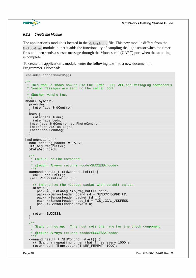
MoteWorks Getting Started Guide
Page 48 Doc. # 7430-0102-01 Rev. G
6.2.2 Create the Module
The application’s module is located in the MyAppM.nc file. This new module differs from the MyAppM.nc module in that it adds the functionality of sampling the light sensor when the timer fires and then sends a sensor message through the Motes serial (UART) port when the sampling is complete.
To create the application’s module, enter the following text into a new document in Programmer’s Notepad:
includes sensorboardApp; /** * This module shows how to use the Timer, LED, ADC and Messaging components * Sensor messages are sent to the serial port * * @author Memsic Inc. **/ module MyAppM { provides { interface StdControl; } uses { interface Timer; interface Leds; interface StdControl as PhotoControl; interface ADC as Light; interface SendMsg; } } implementation { bool sending_packet = FALSE; TOS_Msg msg_buffer; XDataMsg *pack; /** * Initialize the component. * * @return Always returns <code>SUCCESS</code> **/ command result_t StdControl.init() { call Leds.init(); call PhotoControl.init(); // Initialize the message packet with default values atomic { pack = (XDataMsg *)&(msg_buffer.data); pack->xSensorHeader.board_id = SENSOR_BOARD_ID; pack->xSensorHeader.packet_id = 2; pack->xSensorHeader.node_id = TOS_LOCAL_ADDRESS; pack->xSensorHeader.rsvd = 0; } return SUCCESS; } /** * Start things up. This just sets the rate for the clock component. * * @return Always returns <code>SUCCESS</code> **/ command result_t StdControl.start() { // Start a repeating timer that fires every 1000ms return call Timer.start(TIMER_REPEAT, 1000);

MoteWorks Getting Started Guide
Doc. # 7430-0102-01 Rev. G Page 49
} /** * Halt execution of the application. * This just disables the clock component. * * @return Always returns <code>SUCCESS</code> **/ command result_t StdControl.stop() { return call Timer.stop(); } /** * Toggle the red LED in response to the <code>Timer.fired</code> event. * Start the Light sensor control and sample the data * * @return Always returns <code>SUCCESS</code> **/ event result_t Timer.fired() { call Leds.redToggle(); call PhotoControl.start(); call Light.getData(); return SUCCESS; } /** * Stop the Light sensor control, build the message packet and send **/ void task SendData() { call PhotoControl.stop(); if (sending_packet) return; atomic sending_packet = TRUE; // send message to UART (serial) port if (call SendMsg.send(TOS_UART_ADDR,sizeof(XDataMsg),&msg_buffer) != SUCCESS) sending_packet = FALSE; return; } /** * Light ADC data ready * Toggle yellow LED to signal Light sensor data sampled * * @return Always returns <code>SUCCESS</code> **/ async event result_t Light.dataReady(uint16_t data) { atomic pack->xData.datap1.light = data; atomic pack->xData.datap1.vref = 417; // a dummy 3V reference voltage, 1252352/3000 = 417 post SendData(); call Leds.yellowToggle(); return SUCCESS; } /** * Sensor data has been sucessfully sent over the UART (serial port) * Toggle green LED to signal message sent * * @return Always returns <code>SUCCESS</code>

MoteWorks Getting Started Guide
Page 50 Doc. # 7430-0102-01 Rev. G
**/ event result_t SendMsg.sendDone(TOS_MsgPtr msg, result_t success) { call Leds.greenToggle(); atomic sending_packet = FALSE; return SUCCESS; }
When finished save the file with File > Save As… using the following parameters:
File name MyAppM.nc
Save as type All files (“.”)
File format No change to file format
6.2.3 Compile and Install the Code in a Mote
Please Refer to section 5.2.5 to compile and install this application on a Mote plugged into the programming board.
When the application is installed and running on the Mote you should see the red, green and yellow LED’s blinking every second. Each LED is used to indicate the progression of firing the timer, sampling the light sensor and then sending the message back to the base station.
NOTE: Make sure you have connected a sensorboard (MTS300, MTS310 or MDA100) to the underside of the MIB510 programming board. This will allow the application to sample the light sensor. The application will run if you don’t connect the sensorboard however the light value will not be valid when we display the sensor message on the PC.
Table 6-1. Mote LED Status
LED Toggle Indication
Red 1 second timer event fired
Yellow Light sensor has been sampled
Green Sensor message has been sent back to base station
6.2.4 Parsing Message Packets on PC using XServe
The next part of the tutorial involves displaying the sensor message packet contents as they arrive on the PC over the serial port. The tool we use for this is called XServe. XServe is an application that installs with MoteWorks for this purpose. XServe has many other features including automatic logging of sensor messages to a database such as PostgreSQL.
1. XServe is a program that runs within a Cygwin command prompt window. The first step is to open a Cygwin command prompt by double clicking on the icon located on your desktop.

MoteWorks Getting Started Guide
Doc. # 7430-0102-01 Rev. G Page 51
2. Type xserve –device=COM1 at the command prompt and hit enter, you should see output similar to the following when the sensor message packets arrive over the serial port and are displayed by XServe:
NOTE: Substitute your specific COM port for COM1 above according to your particular hardware setup.
You may notice that the message packet contains data fields for other sensors that we are not using with our sensing application – all set to 0. You should see a valid light value however – this is the part of the message that our application is filling in. The reason the other fields are present in the packet is because we are using a standard packet format that XServe knows about.
6.2.5 Sending Sensor Data over the Radio
With a slight modification this application can be altered to send the message packet over the Mote radio to another Mote plugged into the base station instead of directly through the serial port (UART). The only change needed is a single line of code in the MyAppM.nc file:
From
if (call SendMsg.send(TOS_UART_ADDR,sizeof(XDataMsg),&msg_buffer) != SUCCESS)
To
if (call SendMsg.send(TOS_BCAST_ADDR,sizeof(XDataMsg),&msg_buffer) != SUCCESS)
The SendMsg.send command uses the first parameter to decide where the message packet should be sent. Changing from TOS_UART_ADDR to TOS_BCAST_ADDR tells the communications component to send the message through the radio instead of the UART. Setting this parameter to TOS_BCAST_ADDR actually sends the message to any Mote within range, i.e. broadcast the message. If we want to send the message specifically to the base station we can set this parameter value to 0. The Mote plugged into the base station always has a node id of 0.
This modification is provided for you in the /lesson_3 folder.

MoteWorks Getting Started Guide
Page 52 Doc. # 7430-0102-01 Rev. G
6.2.6 Using XSniffer to View Sensor Data Sent Over the Radio
MoteWorks includes a tool named XSniffer that can be used to eavesdrop on messages sent over the Mote radios. We will use the XSniffer tool to monitor the messages sent from our modified sensing application from section 6.2.5.
First, install the modified sensing application located in the /lesson_3 folder onto a Mote. You can compile and install the application in a single step using Programmer’s Notepad as follows:
• Load the MyApp.nc file from /lesson_3 into Programmer’s Notepad
• Select Tools > shell. When prompted for parameters, type in make mica2 install,1 mib510,com1 (assuming MICA2 Mote)
Remove the Mote from the programming board, plug one of the sensorboards (MDA100, MTS300 or MTS310) onto the Mote, make sure it has batteries and turn it on. You should see all three LEDs blinking every second.
Next, install the XSniffer application onto another Mote that remains plugged into your programming board (base station). This application is located in the /MoteWorks/apps/general/XSniffer folder. Install this application with a node id of 2 using Programmer’s Notepad:
• Load the TOSBase.nc file from /MoteWorks/apps/general/XSniffer into Programmer’s Notepad
• Select Tools > shell. When prompted for parameters, type make mica2 install,2 mib510,com1 (assuming MICA2 Mote and PC connected to COM1)
Now, keep the Mote you just programmed plugged into the programming board and start the XSniffer application by double clicking on the icon located on your desktop. Click on the “Options” tab within XSniffer and select the “General Packet Type” radio button. Go back to the Log tab, select the COM port that is connected to the programming board and then click on Start to begin “sniffing” the radio traffic. After a short time you should see message packets displayed in XSniffer similar to Figure 6-1.
NOTE: If you are in the Run mode, you need to Pause the XSniffer before you can change any of the parameters in Options tab and then click on Continue to make the changes take effect.
Figure 6-1. XSniffer Log Screen Display

MoteWorks Getting Started Guide
Doc. # 7430-0102-01 Rev. G Page 53
You can see from the elapsed time the messages are begin sent about 1 second apart – each time the LEDs blink you should see a new message captured by XSniffer.
6.3 A Closer Look at MyApp The MyApp application developed in this chapter builds on the basic MyApp application from Chapter 5. There are two additional features incorporated into this application. First, we are sampling the sensorboard light sensor. Second, we are building a message packet that includes this light sensor value and sending it back to the base station either directly through the UART or over the radio.
6.3.1 Using a Sensorboard
The first thing we need to do when building a sensing application is to specify the sensorboard we want to use. For the MyApp application this is specified in the Makefile.component file as follows:
SENSORBOARD=mts310
This line in the Makefile.component file tells the nesC compiler to link in all the TinyOS components required to access the sensors on the MTS310 sensorboard. The components for the MTS310 sensorboard are located in the /MoteWorks/tos/sensorboards/mts310 folder. There are similar components for other sensorboards located in subfolders under /MoteWorks/tos/sensorboards.
6.3.2 Sampling the Light Sensor
In order to sample the light sensor on the MTS310 sensorboard we need to include a component named Photo in our configuration file. The Photo component implements the StdControl interface for turning on and off the light sensor and the ADC interface for sampling the sensor value through the hardware ADC port.
Here is part of the implementation section from the MyApp.nc configuration file:
implementation { components Main, MyAppM, TimerC, LedsC, Photo, GenericComm as Comm; Main.StdControl -> TimerC.StdControl; Main.StdControl -> MyAppM.StdControl; Main.StdControl -> Comm.Control; MyAppM.Timer -> TimerC.Timer[unique("Timer")]; MyAppM.Leds -> LedsC.Leds; MyAppM.PhotoControl -> Photo.PhotoStdControl; MyAppM.Light -> Photo.ExternalPhotoADC; …
You can see we are connecting the MyAppM.PhotoControl (StdControl interface) to the Photo.PhotoStdControl (StdControl interface for the light sensor) and the MyAppM.Light (ADC interface) to the Photo.ExternalPhotoADC (ADC interface for light sensor).

MoteWorks Getting Started Guide
Page 54 Doc. # 7430-0102-01 Rev. G
We have seen the StdControl interface before, so let’s take a closer look at the ADC Interface:
interface ADC { async command result_t getData(); async command result_t getContinuousData(); async event result_t dataReady(uint16_t data); }
The ADC interface is specified with two commands: getData and getContinuousData and one event dataReady. Quite simply when we want to sample the current light value we call the getData command. This will start a process of sampling the light sensor through the processor hardware ADC interface. At some later time this process will complete and we will receive the current light sensor value through the dataReady event.
Here are the excerpts from the MyAppM.nc module where we sample the light sensor and then receive the callback event with the sampled value:
event result_t Timer.fired() { call Leds.redToggle(); call PhotoControl.start(); call Light.getData(); … async event result_t Light.dataReady(uint16_t data) { atomic pack->xData.datap1.light = data; atomic pack->xData.datap1.vref = 417; // a dummy 3V reference voltage, 1252352/3000 = 417 post SendData(); call Leds.yellowToggle(); …
First, we can see that in the Timer.fired event function we first turn on the light sensor by calling the start command through the StdControl interface. Next we call the getData command through the ADC interface to start the process of sampling the current light value. At some time in the near future when the sampling has completed we then receive a callback in the form of a dataReady event. The dataReady event passes the 16-bit (10 significant bits) light sensor value that we store in our message packet for sending later.
The last thing we do is to post a task to send a message containing the sensor data – this is discussed next.
6.3.3 Sending a Message Packet
In order to send a message containing the sensor data back to the base station we need access to the TinyOS communication component named GenericComm. GenericComm is able to send messages through the UART port or over the radio depending on the destination node address specified.
implementation { components Main, MyAppM, TimerC, LedsC, Photo, GenericComm as Comm; Main.StdControl -> TimerC.StdControl; Main.StdControl -> MyAppM.StdControl; Main.StdControl -> Comm.Control;

MoteWorks Getting Started Guide
Doc. # 7430-0102-01 Rev. G Page 55
… MyAppM.SendMsg -> Comm.SendMsg[AM_XSXMSG]; …
If we take another look at the MyApp.nc configuration file we can see that GenericComm (aliased as Comm) is connected through its Comm.Control (StdControl) interface and that the MyAppM module connects to one instance of the Comm.SendMsg interface. The AM_XSXMSG identifies the active message type. This value is used to distinguish between multiple messages you may wish to send.
Let’s take a closer look at the SendMsg interface:
interface SendMsg { command result_t send(uint16_t address, uint8_t length, TOS_MsgPtr msg); event result_t sendDone(TOS_MsgPtr msg, result_t success); }
The SendMsg interface specifies one command named send and one event named sendDone. When we want to send a message we simply call the send command with the correct parameters. We receive the sendDone event after the message has been sent.
Each message that is sent using the SendMsg interface is defined by a data structure named TOS_Msg:
typedef struct TOS_Msg { /* The following fields are transmitted/received on the radio. */ uint16_t addr; uint8_t type; uint8_t group; uint8_t length; int8_t data[TOSH_DATA_LENGTH]; } typedef TOS_Msg *TOS_MsgPtr;
Where:
addr – the destination address type – the active message type (AM_XSXMSG for this application) group – group id specified during programming length – the payload length data – variable length payload area (sensor data)
The data region in the TOS_Msg is where we place our application specific payload. The following excerpt is from the MyAppM.nc module that shows how we initialize the payload area of the TOS_Msg for our specific sensor application: command result_t StdControl.init() { … // Initialize the message packet with default values atomic {
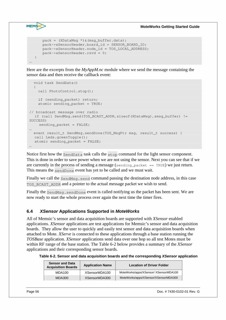
MoteWorks Getting Started Guide
Page 56 Doc. # 7430-0102-01 Rev. G
pack = (XDataMsg *)&(msg_buffer.data); pack->xSensorHeader.board_id = SENSOR_BOARD_ID; pack->xSensorHeader.node_id = TOS_LOCAL_ADDRESS; pack->xSensorHeader.rsvd = 0; } …
Here are the excerpts from the MyAppM.nc module where we send the message containing the sensor data and then receive the callback event:
void task SendData() { call PhotoControl.stop(); if (sending_packet) return; atomic sending_packet = TRUE; // broadcast message over radio if (call SendMsg.send(TOS_BCAST_ADDR,sizeof(XDataMsg),&msg_buffer) != SUCCESS) sending_packet = FALSE; … event result_t SendMsg.sendDone(TOS_MsgPtr msg, result_t success) { call Leds.greenToggle(); atomic sending_packet = FALSE; …
Notice first how the SendData task calls the stop command for the light sensor component. This is done in order to save power when we are not using the sensor. Next you can see that if we are currently in the process of sending a message (sending_packet == TRUE) we just return. This means the sendDone event has yet to be called and we must wait.
Finally we call the SendMsg.send command passing the destination node address, in this case TOS_BCAST_ADDR and a pointer to the actual message packet we wish to send.
Finally the SendMsg.sendDone event is called notifying us the packet has been sent. We are now ready to start the whole process over again the next time the timer fires.
6.4 XSensor Applications Supported in MoteWorks All of Memsic’s sensor and data acquisition boards are supported with XSensor enabled applications. XSensor applications are test applications for Memsic’s sensor and data acquisition boards. They allow the user to quickly and easily test sensor and data acquisition boards when attached to Mote. XServe is connected to these applications through a base station running the TOSBase application. XSensor applications send data over one hop so all test Motes must be within RF range of the base station. The Table 6-2 below provides a summary of the XSensor applications and their corresponding sensor boards.
Table 6-2. Sensor and data acquisition boards and the corresponding XSensor application
Sensor and Data Acquisition Boards Application Name Location of Driver Folder
MDA100 XSensorMDA100 MoteWorks/apps/XSensor/ XSensorMDA100
MDA300 XSensorMDA300 MoteWorks/apps/XSensor/XSensorMDA300

MoteWorks Getting Started Guide
Doc. # 7430-0102-01 Rev. G Page 57
MDA320 XSensorMDA320 MoteWorks/apps/XSensor/XSensorMDA320
MDA325 XSensorMDA325 MoteWorks/apps/XSensor/XSensorMDA325
MDA500 XSensorMDA500 MoteWorks/apps/XSensor/XSensorMDA500
MEP410 XSensorMEP410 MoteWorks/apps/XSensor/XMEP410
MEP510 XSensorMEP510 MoteWorks/apps/XSensor/XSensorMEP510
MTS101 XSensorMTS101 MoteWorks/apps/XSensor/XSensorMTS101
MTS300/310 XSensorMTS300 MoteWorks/apps/XSensor/XSensorMTS300
MTS400/420 XSensorMTS400 MoteWorks/apps/XSensor/XSensorMTS400
MTS410 XSensorMTS410 MoteWorks/apps/XSensor/XSensorMTS410
MTS420CC XSensorMTS420CC MoteWorks/apps/ XSensor/XSensorMTS420CC
MTS450 XSensorMTS450 MoteWorks/apps/XSensor/XSensorMTS450
MTS510 XSensorMTS510 MoteWorks/apps/XSensor/XSensorMTS510

MoteWorks Getting Started Guide
Page 58 Doc. # 7430-0102-01 Rev. G
7 XMesh enabled Sensing Application
In this chapter you will learn:
• How to enhance the sensing application developed in the last chapter with the XMesh multi-hop networking service
• Using XServe to parse packets on a PC
• Using XSniffer to display the sensor data message on a PC
• Using MoteView to display the sensor data message on a PC
7.1 Hardware Requirements This chapter requires the following hardware:
• Three Motes: standard editions of MICA2 (MPR4x0), MICAz (MPR2400), IRIS (XM2110) or OEM editions MPR600, MPR2600, M2110
• One sensor or data acquisition board: MDA100, MTS300 or MTS310
• One gateway/programming board: MIB510, MIB520, or MIB600 and associated accessories (cables, power supply) for each
• A Window’s PC with MoteWorks & MoteView installed
7.2 An XMesh enabled Sensing application: MyApp A simple sensing application that samples the light sensor on a sensor board, packetizes, and sends the data back to the base station using the XMesh multi-hop networking service is presented here to help further familiarize you with nesC programming and TinyOS messaging.
The following enhancements will be made to the simple Sensor application presented in Chapter 6:
• Use the Mote radio to send sensor data to the base station using the XMesh multi-hop networking service.
• Compile and debug if necessary
To get started the first thing to do is to create the application folder (directory) where all your application code and other files will be stored.
1. Change into the directory /MoteWorks/apps/tutorials/ and create a new subfolder (subdirectory) named after your application. In this lesson the application will be called MyApp.
2. Once again you have two options to create the source files. You can copy, paste, and rename the subdirectory /lesson_4 found in the /tutorials subdirectory and avoid some typing. If you choose to do this you can go straight to the compiling and installation step. Or you can follow these instructions and learn along the way.
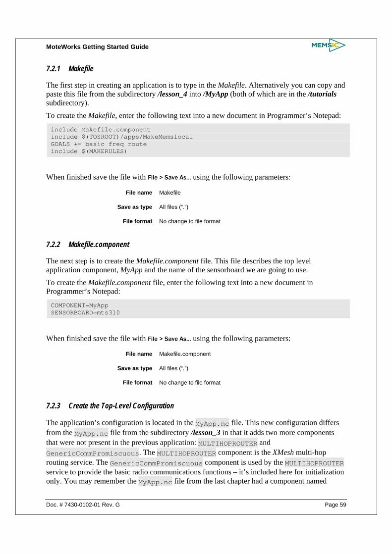
MoteWorks Getting Started Guide
Doc. # 7430-0102-01 Rev. G Page 59
7.2.1 Makefile
The first step in creating an application is to type in the Makefile. Alternatively you can copy and paste this file from the subdirectory /lesson_4 into /MyApp (both of which are in the /tutorials subdirectory).
To create the Makefile, enter the following text into a new document in Programmer’s Notepad:
include Makefile.component include $(TOSROOT)/apps/MakeMemslocal GOALS += basic freq route include $(MAKERULES)
When finished save the file with File > Save As… using the following parameters:
File name Makefile
Save as type All files (“.”)
File format No change to file format
7.2.2 Makefile.component
The next step is to create the Makefile.component file. This file describes the top level application component, MyApp and the name of the sensorboard we are going to use.
To create the Makefile.component file, enter the following text into a new document in Programmer’s Notepad:
COMPONENT=MyApp SENSORBOARD=mts310
When finished save the file with File > Save As… using the following parameters:
File name Makefile.component
Save as type All files (“.”)
File format No change to file format
7.2.3 Create the Top-Level Configuration
The application’s configuration is located in the MyApp.nc file. This new configuration differs from the MyApp.nc file from the subdirectory /lesson_3 in that it adds two more components that were not present in the previous application: MULTIHOPROUTER and GenericCommPromiscuous. The MULTIHOPROUTER component is the XMesh multi-hop routing service. The GenericCommPromiscuous component is used by the MULTIHOPROUTER service to provide the basic radio communications functions – it’s included here for initialization only. You may remember the MyApp.nc file from the last chapter had a component named

MoteWorks Getting Started Guide
Page 60 Doc. # 7430-0102-01 Rev. G
GenericComm. GenericCommPromiscuous is similar in functionality but provides other features required by XMesh such as the ability to “snoop” on radio conversations.
To create the application’s configuration, enter the following text into a new document in Programmer’s Notepad:
#include "appFeatures.h" includes sensorboardApp; /** * This configuration shows how to use the Timer, LED, ADC and XMesh * components. * Sensor messages are sent multi-hop over the RF radio * **/ configuration MyApp { } implementation { components Main, GenericCommPromiscuous as Comm, MULTIHOPROUTER, MyAppM, TimerC, LedsC, Photo; (still using older version of the wiring – see xmesh manual) Main.StdControl -> TimerC.StdControl; Main.StdControl -> MyAppM.StdControl; Main.StdControl -> Comm.Control; Main.StdControl -> MULTIHOPROUTER.StdControl; MyAppM.Timer -> TimerC.Timer[unique("Timer")]; MyAppM.Leds -> LedsC.Leds; MyAppM.PhotoControl -> Photo.PhotoStdControl; MyAppM.Light -> Photo.ExternalPhotoADC; MyAppM.RouteControl -> MULTIHOPROUTER; MyAppM.Send -> MULTIHOPROUTER.MhopSend[AM_XMULTIHOP_MSG]; MULTIHOPROUTER.ReceiveMsg[AM_XMULTIHOP_MSG] ->Comm.ReceiveMsg[AM_XMULTIHOP_MSG]; }
When finished save the file with File > Save As… using the following parameters:
File name MyApp.nc
Save as type All files (“.”)
File format No change to file format
7.2.4 Create the Module
The application’s module is located in the MyAppM.nc file. This new module differs from the MyAppM.nc module from the subdirectory /lesson_3 in that it sends the sensor message over the Mote radio using the XMesh routing service.
To create the application’s module, enter the following text into a new document in Programmer’s Notepad:

MoteWorks Getting Started Guide
Doc. # 7430-0102-01 Rev. G Page 61
#include "appFeatures.h" includes MultiHop; //includes sensorboard; /** * This module shows how to use the Timer, LED, ADC and XMesh * components. * Sensor messages are sent multi-hop over the RF radio **/ module MyAppM { provides { interface StdControl; } uses { interface Timer; interface Leds; interface StdControl as PhotoControl; interface ADC as Light; interface MhopSend as Send; interface RouteControl; } } implementation { bool sending_packet = FALSE; TOS_Msg msg_buffer; XDataMsg *pack; /** * Initialize the component. * * @return Always returns <code>SUCCESS</code> **/ command result_t StdControl.init() { uint16_t len; call Leds.init(); call PhotoControl.init(); // Initialize the message packet with default values atomic { pack = (XDataMsg*)call Send.getBuffer(&msg_buffer, &len); pack->board_id = SENSOR_BOARD_ID; pack->packet_id = 4; } return SUCCESS; } /** * Start things up. This just sets the rate for the clock component. * * @return Always returns <code>SUCCESS</code> **/ command result_t StdControl.start() { // Start a repeating timer that fires every 1000ms return call Timer.start(TIMER_REPEAT, 1000); }

MoteWorks Getting Started Guide
Page 62 Doc. # 7430-0102-01 Rev. G
/** * Halt execution of the application. * This just disables the clock component. * * @return Always returns <code>SUCCESS</code> **/ command result_t StdControl.stop() { return call Timer.stop(); } /** * Toggle the red LED in response to the <code>Timer.fired</code> event. * Start the Light sensor control and sample the data * * @return Always returns <code>SUCCESS</code> **/ event result_t Timer.fired() { call Leds.redToggle(); call PhotoControl.start(); call Light.getData(); return SUCCESS; } /** * Stop the Light sensor control, build the message packet and send **/ void task SendData() { call PhotoControl.stop(); if (sending_packet) return; atomic sending_packet = TRUE; // send message to XMesh multi-hop networking layer pack->parent = call RouteControl.getParent(); if (call Send.send(BASE_STATION_ADDRESS,MODE_UPSTREAM,&msg_buffer,sizeof(XDataMsg)) != SUCCESS) sending_packet = FALSE; return; } /** * Light ADC data ready * Toggle yellow LED to signal Light sensor data sampled * * @return Always returns <code>SUCCESS</code> **/ async event result_t Light.dataReady(uint16_t data) { atomic pack->light = data; atomic pack->vref = 417; // a dummy 3V reference voltage, 1252352/3000 = 417 post SendData(); call Leds.yellowToggle();

MoteWorks Getting Started Guide
Doc. # 7430-0102-01 Rev. G Page 63
return SUCCESS; } /** * Sensor data has been sucessfully sent through XMesh * Toggle green LED to signal message sent * * @return Always returns <code>SUCCESS</code> **/ event result_t Send.sendDone(TOS_MsgPtr msg, result_t success) { call Leds.greenToggle(); atomic sending_packet = FALSE; return SUCCESS; } }
When finished save the file with File > Save As… using the following parameters:
File name MyAppM.nc
Save as type All files (“.”)
File format No change to file format
7.2.5 Compile and Install the Code in a Mote
Before proceeding you should have all the application files typed in and saved using Programmer’s Notepad or copied over from the /lesson_4 folder.
This application will require two Motes and one sensorboard (MDA100, MTS300 or MTS310). One Mote will function as the sensor node with the sensorboard plugged into it and a second Mote will function as the base station plugged into the programming board and connected to your PC. The Mote that functions as the sensor node will need to have batteries plugged into it. The Mote that functions as the base station does not require batteries.
Plug the Mote that will function as the sensor node into the programming board. To compile and install the MyApp application onto the sensor node:
• Select the MyApp.nc file in Programmer’s Notepad
• Select Tools > shell. When prompted for parameters, type make mica2 install,1 mib510,com1 (assuming MICA2 Mote and PC connected to COM1)
Next, plug the Mote that will function as the base station into the programming board. This Mote will be programmed with a special application named XMeshBase located in the /MoteWorks/apps/xmesh/XMeshBase folder. To compile and install the XMeshBase application onto the base station node:
• Select the XMeshBase.nc file in Programmer’s Notepad
• Select Tools > shell. When prompted for parameters, type make mica2 install,0 mib510,com1 (assuming MICA2 Mote and PC connected to COM1).
NOTE: The Mote that functions as the base station is always programmed with node id of 0.
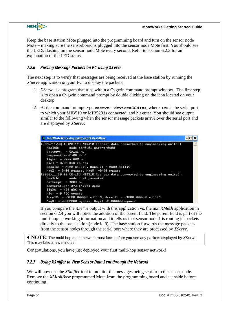
MoteWorks Getting Started Guide
Page 64 Doc. # 7430-0102-01 Rev. G
Keep the base station Mote plugged into the programming board and turn on the sensor node Mote – making sure the sensorboard is plugged into the sensor node Mote first. You should see the LEDs flashing on the sensor node Mote every second. Refer to section 6.2.3 for an explanation of the LED status.
7.2.6 Parsing Message Packets on PC using XServe
The next step is to verify that messages are being received at the base station by running the XServe application on your PC to display the packets.
1. XServe is a program that runs within a Cygwin command prompt window. The first step is to open a Cygwin command prompt by double clicking on the icon located on your desktop.
2. At the command prompt type xserve –device=COM<x>, where <x> is the serial port to which your MIB510 or MIB520 is connected, and hit enter. You should see output similar to the following when the sensor message packets arrive over the serial port and are displayed by XServe:
If you compare the XServe output with this application vs. the non XMesh application in section 6.2.4 you will notice the addition of the parent field. The parent field is part of the multi-hop networking information and it tells us that sensor node 1 is routing its packets directly to the base station (node id 0). The base station forwards the message packets from the sensor nodes through the serial port where they are processed by XServe.
NOTE: The multi-hop mesh network must form before you see any packets displayed by XServe. This may take a few minutes.
Congratulations, you have just deployed your first multi-hop sensor network!
7.2.7 Using XSniffer to View Sensor Data Sent through the Network
We will now use the XSniffer tool to monitor the messages being sent from the sensor node. Remove the XMeshBase programmed Mote from the programming board and set aside before continuing.

MoteWorks Getting Started Guide
Doc. # 7430-0102-01 Rev. G Page 65
NOTE XSniffer currently does not support the MIB600 programming board. XSniffer tool will work only while using XMesh–based applications in the tutorial lessons.
Install the XSniffer application onto a third Mote that you will plug into your programming board (base station). This application is located in the /MoteWorks/apps/general/XSniffer folder. Install this application with a node id of 2 using Programmer’s Notepad:
• Open the TosBase.nc file from /MoteWorks/apps/general/XSniffer using Programmer’s Notepad
• Select Tools > shell. When prompted for parameters, type make mica2 install,2 mib510,com1 (assuming MICA2 Mote and PC connected to COM1)
Now, keep the Mote you just programmed plugged into the programming board and start the XSniffer application by double clicking on the icon located on your desktop.
Click on the Options tab within XSniffer and select the XMesh Packet Type radio button. Go back to the Log tab, select the COM port that is connected to the programming board and then click on Start to begin “sniffing” the radio traffic. After a short time you should see message packets displayed in XSniffer similar to Figure 7-1.
Figure 7-1. XSniffer Log Screen Display
You can see from the elapsed time the messages are begin sent about 1 second apart – each time the LEDs blink you should see a new message captured by XSniffer.
There are a couple of interesting things to note. First, look at the destination address field Addr. The value for this field is Bcast which means the sensor node id 1 (Src column) is broadcasting its packet to all nodes. This is the initial state of XMesh until the multi-hop network has formed efficient routes. Second, you can see there are two types of messages being sent by the sensor node (identified by Type field). Message type DatUp identifies a message as a data message sent upstream from the sensor node to the base station. Message type Rte designates a route update message. Route update messages are periodically sent by all nodes in a mesh network for the purpose of updating each other’s routing tables.

MoteWorks Getting Started Guide
Page 66 Doc. # 7430-0102-01 Rev. G
So far we can see the messages from one sensor node. Remember we removed the XMeshBase Mote from the programming board – without a base station Mote, XMesh cannot form the multi-hop network. Now find the XMeshBase Mote we set aside earlier, make sure it has batteries and then turn it on.
As the messages flow into XSniffer, you should begin to see some interesting things.
Figure 7-2. XSniffer Log Screen Display
After turning on the XMeshBase Mote you will start to see Rte (route update) messages being generated for node 0 – the base station. The sensor node Mote will see these Rte messages and will eventually add the base station Mote as its parent. Once this happens you will see the DatUp (data messages upstream to base) from node 1 being sent directly to the base station node 0 instead of being broadcast. The base station id 0 is denoted as Base in the Addr field.
You have just witnessed a two node multi-hop mesh network being formed using XSniffer!
7.2.8 Viewing your Sensor Network with MoteView
As valuable as the XServe and XSniffer tools are for monitoring sensor networks, we are now going to focus on a more feature rich client application named MoteView.
The MoteView application is installed separately from MoteWorks and may be downloaded free from the Memsic web site. Make sure you also download the MoteView User’s Manual.
Please download and install MoteView before continuing.
We are now going to use MoteView to view our two node sensor network. Double click on the icon located on your desktop. You should see something similar to the Figure 7-3 when MoteView loads.
NOTE

MoteWorks Getting Started Guide
Doc. # 7430-0102-01 Rev. G Page 67
MoteView is only supported and can be used as monitoring tool for the tutorial lesson_4 lesson_5 and lesson_6, which use XMesh feature.
Figure 7-3. MoteView GUI Display
To view the sensor network data using MoteView perform the follow steps:
• Remove the XSniffer Mote from the programming board and plug the XMeshBase Mote (base station) back into the programming board
• From the MoteView main menu select File > Connect > Connect to Database
• Select mts310_results in the table name drop down list and click on Apply
• From the MoteView main menu select File > Connect > Connect to MIB510/MIB520/MIB600/Stargate.
Set the COM port value to the correct value for your setup
Select the XMTS310 application from the XMesh Application drop down list
Select the Advanced tab. In Data Logging Options menu, check the box for Spawn Separate Shell.
• Click on Start. You will see XServe start-up enabled to log sensor data to the database
After a few minutes you should see XServe logging sensor data to the database similar to Figure 7-4.

MoteWorks Getting Started Guide
Page 68 Doc. # 7430-0102-01 Rev. G
Figure 7-4. XServe Log Screen Display
Now move back to the main MoteView window and you should see the sensor data from node 1 displayed in the data view similar to Figure 7-5.
Figure 7-5. MoteView GUI Displaying Sensor Data
Congratulations, you have now deployed a complete end-to-end multi-hop sensor network solution!
7.3 A Closer Look at MyApp Let’s examine the specific differences between the MyApp application we developed in Chapter 6 and the MyApp application we have developed in this chapter. The significant difference is the communication service we are using to send the sensor data messages.
The MyApp application from the subdirectory /lesson_3 used the basic GenericComm component for sending a message either directly through the UART port or over the radio – broadcasted or to a specific node address. The MyApp application in this chapter uses the XMesh networking service to multi-hop messages back to the base station. The XMesh service ultimately uses the GenericComm service for sending individual messages but special routing information is added – this is hidden from the application.
MoteWorks Getting Started Guide
Doc. # 7430-0102-01 Rev. G Page 69
To summarize:
GenericComm – single hop, point-to-point communication service
XMesh – multi-hop mesh networking service
Let’s take a closer look at the MyApp.nc configuration file:
configuration MyApp { } implementation { components Main, GenericCommPromiscuous as Comm, MULTIHOPROUTER, MyAppM, TimerC, LedsC, Photo; Main.StdControl -> TimerC.StdControl; Main.StdControl -> MyAppM.StdControl; Main.StdControl -> Comm.Control; Main.StdControl -> MULTIHOPROUTER.StdControl; MyAppM.Timer -> TimerC.Timer[unique("Timer")]; MyAppM.Leds -> LedsC.Leds; MyAppM.PhotoControl -> Photo.PhotoStdControl; MyAppM.Light -> Photo.ExternalPhotoADC; MyAppM.RouteControl -> MULTIHOPROUTER; MyAppM.Send -> MULTIHOPROUTER.MhopSend[AM_XMULTIHOP_MSG]; MULTIHOPROUTER.ReceiveMsg[AM_XMULTIHOP_MSG] ->Comm.ReceiveMsg[AM_XMULTIHOP_MSG]; }
The first thing you notice is that we have added a component named MULTIHOPROUTER. This is the actual component that implements XMesh. The other difference is that the GenericComm component has been replaced by GenericCommPromiscuous. GenericCommPromiscuous adds special radio “snooping” capabilities required by XMesh.
The other thing that looks different is the component wiring. You can see the MyAppM is now using the MhopSend interface instead of the SendMsg interface. XMesh implements the MhopSend interface which looks a little bit different:
interface MhopSend { command result_t send(uint16_t dest, uint8_t mode, TOS_MsgPtr msg, uint16_t length); command void* getBuffer(TOS_MsgPtr msg, uint16_t* length); event result_t sendDone(TOS_MsgPtr msg, result_t success); }
Specifically the send command adds a mode parameter. This parameter specifies the XMesh communication transport mode. In this example we use the MODE_UPSTREAM transport which sends a message in the direction of the base station.
Let’s now take a look at the specific differences in the MyAppM.nc module for sending sensor data messages:
command result_t StdControl.init() { uint16_t len; call Leds.init(); call PhotoControl.init();

MoteWorks Getting Started Guide
Page 70 Doc. # 7430-0102-01 Rev. G
// Initialize the message packet with default values atomic { pack = (XDataMsg*)call Send.getBuffer(&msg_buffer, &len); pack->board_id = SENSOR_BOARD_ID; pack->packet_id = 4; } …
The first change we see is a different message packet being initialized in the StdControl.init function. We call the XMesh Send.getBuffer command which returns a pointer to the payload area in the msg_buffer. We then initialize the standard MTS310 packet with the default values.
void task SendData() { … // send message to XMesh multi-hop networking layer pack->parent = call RouteControl.getParent(); if (call Send.send(BASE_STATION_ADDRESS, MODE_UPSTREAM, &msg_buffer, sizeof(XDataMsg)) != SUCCESS) …
The next difference we see is that the packet must include the current routing parent; this is obtained by making a call to the XMesh RouteControl.getParent command.
We then send the message using the Send.send command specifying the base station as the destination and the transport mode as MODE_UPSTREAM.
event result_t Send.sendDone(TOS_MsgPtr msg, result_t success) { call Leds.greenToggle(); atomic sending_packet = FALSE; …
Finally similar to the MyApp application in Chapter 6 we receive the Send.sendDone event that notifies that the message has been sent.
7.4 XMesh Applications Supported in MoteWorks All of Memsic’s sensor and data acquisition boards are supported with XMesh enabled applications. XServe is connected to these applications through a base station running the XMeshBase application. The Table 7-1 below provides a summary of the XMesh applications and the corresponding sensor boards.
Table 7-1. Sensor and data acquisition boards and the corresponding XMesh application
Sensor and Data Acquisition Boards Application Name Location of Driver Folder
MDA100CA XMDA100 MoteWorks/apps/XMesh/XMDA100
MDA100CB XMDA100CB MoteWorks/apps/XMesh/XMDA100CB
MDA300 XMDA300 MoteWorks/apps/XMesh/XMDA300
MDA 300 (Differential) XMDA300_D MoteWorks/apps/XMesh/XMDA300_D

MoteWorks Getting Started Guide
Doc. # 7430-0102-01 Rev. G Page 71
MDA320 XMDA320 MoteWorks/apps/XMesh/XMDA320
MDA325 XMDA325 MoteWorks/apps/XMesh/XMDA325
MDA500 XMDA500 MoteWorks/apps/XMesh/XMDA500
MEP410 XMEP410 MoteWorks/apps/XMesh/XMEP410
MEP510 XMEP510 MoteWorks/apps/XMesh/XMEP510
MSP410 XMSP410 MoteWorks/apps/XMesh/XMSP410
MTS101 XMTS101 MoteWorks/apps/XMesh/XMTS101
MTS300CA XMTS300 MoteWorks/apps/XMesh/XMTS300
MTS300CB XMTS300CB MoteWorks/apps/XMesh/XMTS300CB
MTS310CA XMTS310 MoteWorks/apps/XMesh/XMTS310
MTS310CB XMTS310CB MoteWorks/apps/XMesh/XMTS310CB
MTS400 XMTS400 MoteWorks/apps/XMesh/XMTS400
MTS410 XMTS410 MoteWorks/apps/XMesh/XMTS410
MTS420CA/MTS420CB XMTS420 MoteWorks/apps/XMesh/XMTS420
MTS420CC XMTS420CC MoteWorks/apps/XMesh/XMTS420CC
MTS450 XMTS450 MoteWorks/apps/XMesh/XMTS450
MTS4510 XMTS510 MoteWorks/apps/XMesh/XMTS510

MoteWorks Getting Started Guide
Page 72 Doc. # 7430-0102-01 Rev. G
8 XMesh Advanced Features
In this chapter you will learn:
• How to use some advanced features of the XMesh multi-hop networking service
o How to use the XMesh end-to-end acknowledgment message transport service
o How to send downstream commands from the base station to individual Motes
8.1 Hardware Requirements This chapter requires the following hardware:
• Two Motes: standard editions of MICA2 (MPR4x0), MICAz (MPR2400), IRIS (XM2110) or OEM editions MPR600, MPR2600, M2110
• One gateway board: MIB510, MIB520, or MIB600 and the associated hardware (cables, power supply) for each
• A Windows PC with MoteWorks installed
8.2 End-to-End Acknowledgements: MyApp from the subdirectory /lesson_5 In this section we will look at an example application, MyApp from the subdirectory /lesson_5 that shows how to use the XMesh end-to-end acknowledgement message transport service.
The following enhancements have been made to the XMesh application presented in Chapter 7:
• Code modified to use the MOTE_UPSTREAM_ACK transport mode to request an acknowledgement back from the base station
• Yellow LED toggles when an acknowledgement message is received back from the base station
There is a class of sensor network applications that requires a 100% reliable delivery of messages to the base station. XMesh implements a special networking transport service that sends acknowledgement messages back to the originating node when the sensor messages arrive at the base station. It is then a simple task of resending the sensor message from the originating node if the acknowledgement is not received back within a certain time.
8.2.1 Compile and Install the Code in a Mote
The MyApp application is located in the /MoteWorks/apps/tutorial/lesson_5 folder. This application will be installed on two motes. One Mote will function as the sensor node and the other will function as the base station. The sample application is installed on both Motes due to the use of the MODE_UPSTREAM_ACK transport mode used. This is a different transport mode than the one used by the XMeshBase application used earlier.
Plug the Mote that will function as the sensor node into the programming board. To compile and install the MyApp application onto the sensor node:
MoteWorks Getting Started Guide
Doc. # 7430-0102-01 Rev. G Page 73
• Select the MyApp.nc file in Programmer’s Notepad
• Select Tools > shell. When prompted for parameters, type make mica2 install,1 mib510,com1 (assuming MICA2 Mote assigned with Node ID 1 and PC connected to COM1)
NOTE: A sensorboard is not required to be plugged into the sensor node Mote.
Next, plug the Mote that will function as the base station into the programming board. This Mote will be programmed with the same XMeshBase application as follows:
• Select the XMeshBase.nc file in Programmer’s Notepad
• Select Tools > shell. When prompted for parameters, type make mica2 reinstall,0 mib510,com1 (assuming MICA2 Mote and PC connected to COM1)
Leave the base station Mote plugged into the programming board.
Make sure you have batteries plugged into the sensor node Mote – the one programmed with id 1 and then turn it on. You should see the red and green LEDs flashing until the mesh network is formed. Once the sensor node has joined the network with the base station (a couple minutes or sooner) you should see the yellow LED flash on the sensor node.
The flashing yellow LED on the sensor node indicates that an acknowledgement message has been received from the base station!
You can also run XServe (see section 7.2.6) or MoteView to display the incoming packets on the PC.
8.3 A Closer Look at MyApp The MyApp application in this chapter has very minimal changes when compared to the MyApp application developed in Chapter 7.
First, let’s look at the MyApp.nc configuration file:
… MyAppM.RouteControl -> MULTIHOPROUTER; MyAppM.Send -> MULTIHOPROUTER.MhopSend[AM_XMULTIHOP_MSG]; MyAppM.ReceiveAck -> MULTIHOPROUTER.ReceiveAck[AM_XMULTIHOP_MSG]; MULTIHOPROUTER.ReceiveMsg[AM_XMULTIHOP_MSG] ->Comm.ReceiveMsg[AM_XMULTIHOP_MSG]; …
The only change to the configuration file is the addition of the ReceiveAck interface wiring. The ReceiveAck interface is required to implement an event callback function that will be generated by XMesh when the acknowledgment message has arrived from the base station.
Let’s now look at the MyAppM.nc module file:
void task SendData() { … if (call Send.send(BASE_STATION_ADDRESS, MODE_UPSTREAM_ACK, &msg_buffer,

MoteWorks Getting Started Guide
Page 74 Doc. # 7430-0102-01 Rev. G
sizeof(XDataMsg)) != SUCCESS) … event TOS_MsgPtr ReceiveAck.receive(TOS_MsgPtr pMsg, void* payload, uint16_t payloadLen) { call Leds.yellowToggle(); …
The first change is the transport mode of MODE_UPSTREAM_ACK. This tells XMesh to send an acknowledgement message back to the message originator when the message is received at the base station.
The second change is the addition of the ReceiveAck.receive event function. This is the event called by XMesh when the acknowledgement message has arrived from the base station for the most recently sent message. The yellow LED is toggled upon receiving this acknowledgment message.
8.3.1 Enhancements for Reliable Message Delivery
This example application shows the basic mechanism for using the XMesh MODE_UPSTREAM_ACK message transport. For a robust real world application it is also necessary to implement a message re-send strategy for cases where the acknowledgment message is not received due to a network problem. The easiest way to do this is to use another timer set to fire after the maximum acknowledgement waiting period – determined by the developer. If the acknowledgement is received before the timer fires you just stop the timer. Otherwise the timer fires indicating you should resend the message. You also want to have a maximum number of message retries before giving up.
NOTE: It is important to remember the MODE_UPSTREAM_ACK transport mode does not guarantee message delivery – this is the responsibility of the application developer.
8.4 Downstream Command Processing: MyApp from the subdirectory /lesson_6 In this section we will look at an example application named MyApp from the subdirectory /lesson_6 that shows how to implement command processing in Motes. We will also show how to send commands to individual Motes using the MoteWorks XServeterm application.
The following enhancements have been made to the XMesh application presented in Chapter 7.
• Code modified to use the XCommand component to intercept and process downstream commands
8.4.1 Compile and Install the Code in a Mote
The MyApp application is located in the /MoteWorks/apps/tutorial/lesson_6 folder. This application will require two Motes. One Mote will function as the sensor node and a second Mote will function as the base station plugged into the programming board and connected to your PC. The Mote that functions as the sensor node will need to have batteries plugged into it. The Mote that functions as the base station does not require batteries.
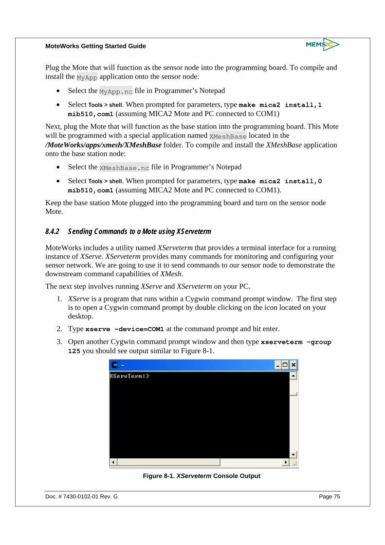
MoteWorks Getting Started Guide
Doc. # 7430-0102-01 Rev. G Page 75
Plug the Mote that will function as the sensor node into the programming board. To compile and install the MyApp application onto the sensor node:
• Select the MyApp.nc file in Programmer’s Notepad
• Select Tools > shell. When prompted for parameters, type make mica2 install,1 mib510,com1 (assuming MICA2 Mote and PC connected to COM1)
Next, plug the Mote that will function as the base station into the programming board. This Mote will be programmed with a special application named XMeshBase located in the /MoteWorks/apps/xmesh/XMeshBase folder. To compile and install the XMeshBase application onto the base station node:
• Select the XMeshBase.nc file in Programmer’s Notepad
• Select Tools > shell. When prompted for parameters, type make mica2 install,0 mib510,com1 (assuming MICA2 Mote and PC connected to COM1).
Keep the base station Mote plugged into the programming board and turn on the sensor node Mote.
8.4.2 Sending Commands to a Mote using XServeterm
MoteWorks includes a utility named XServeterm that provides a terminal interface for a running instance of XServe. XServeterm provides many commands for monitoring and configuring your sensor network. We are going to use it to send commands to our sensor node to demonstrate the downstream command capabilities of XMesh.
The next step involves running XServe and XServeterm on your PC.
1. XServe is a program that runs within a Cygwin command prompt window. The first step is to open a Cygwin command prompt by double clicking on the icon located on your desktop.
2. Type xserve –device=COM1 at the command prompt and hit enter.
3. Open another Cygwin command prompt window and then type xserveterm –group 125 you should see output similar to Figure 8-1.
Figure 8-1. XServeterm Console Output
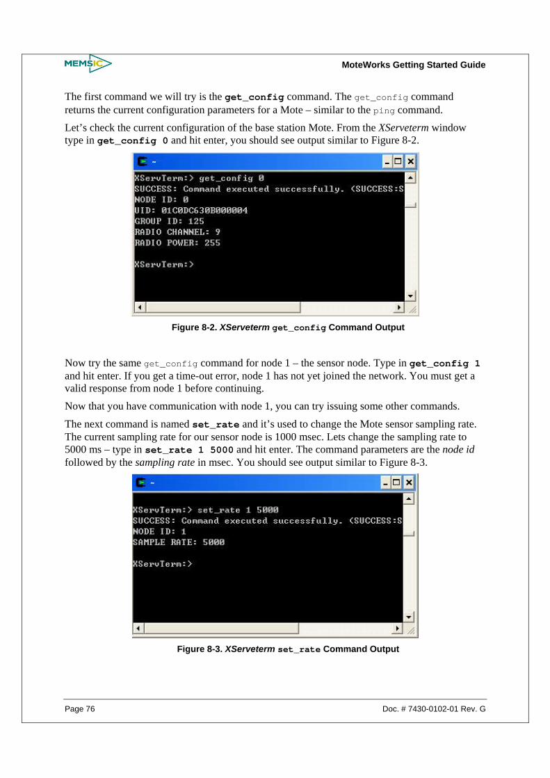
MoteWorks Getting Started Guide
Page 76 Doc. # 7430-0102-01 Rev. G
The first command we will try is the get_config command. The get_config command returns the current configuration parameters for a Mote – similar to the ping command.
Let’s check the current configuration of the base station Mote. From the XServeterm window type in get_config 0 and hit enter, you should see output similar to Figure 8-2.
Figure 8-2. XServeterm get_config Command Output
Now try the same get_config command for node 1 – the sensor node. Type in get_config 1 and hit enter. If you get a time-out error, node 1 has not yet joined the network. You must get a valid response from node 1 before continuing.
Now that you have communication with node 1, you can try issuing some other commands.
The next command is named set_rate and it’s used to change the Mote sensor sampling rate. The current sampling rate for our sensor node is 1000 msec. Lets change the sampling rate to 5000 ms – type in set_rate 1 5000 and hit enter. The command parameters are the node id followed by the sampling rate in msec. You should see output similar to Figure 8-3.
Figure 8-3. XServeterm set_rate Command Output

MoteWorks Getting Started Guide
Doc. # 7430-0102-01 Rev. G Page 77
You should now notice that the LEDs on node 1 are blinking much slower than before – every 5000 ms. This means the light sensor is now being sampled and reported every 5 seconds instead of the original 1 second.
The other command that we can try is to control the state of the LEDs. The LEDs are controlled using the actuate command as follows: actuate <destination address> <device> <state> device ids states ---------- ------ green led 0 off 0 yellow led 1 on 1 red led 2 toggle 2 all leds 3 sounder 4 relay1 5 relay2 6 relay3 7
Toggle the yellow LED on node 1 by typing actuate 1 1 2.
8.5 A Closer Look at MyApp The MyApp application from the subdirectory /lesson_6 is also based on the MyApp application developed in Chapter 7. Minimal changes are required for implementing command processing.
Let’s look at the changes for the MyApp.nc configuration file: configuration MyApp { } implementation { components Main, GenericCommPromiscuous as Comm, MULTIHOPROUTER, MyAppM, TimerC, LedsC, Photo, XCommandC; … MyAppM.RouteControl -> MULTIHOPROUTER; MyAppM.Send -> MULTIHOPROUTER.MhopSend[AM_XMULTIHOP_MSG]; MyAppM.XCommand -> XCommandC; MULTIHOPROUTER.ReceiveMsg[AM_XMULTIHOP_MSG] ->Comm.ReceiveMsg[AM_XMULTIHOP_MSG]; …
The first change you will notice is the addition of the XCommandC component. This is the component that provides the basic functionality for processing downstream commands.
Next you will notice that XCommandC is wired to MyAppM module through the XCommand interface.
Here is the definition for the XCommand interface: interface XCommand { event result_t received(XCommandOp *op); }
The XCommand interface provides one single event named received which must be implemented in your application module – in this case MyAppM.nc. The received event is signaled when a command arrives for the node.
Here are the changes made to the MyAppM.nc module file:

MoteWorks Getting Started Guide
Page 78 Doc. # 7430-0102-01 Rev. G
event result_t XCommand.received(XCommandOp *opcode) { uint16_t timer = 0; switch (opcode->cmd) { case XCOMMAND_SET_RATE: // Change the data collection rate. timer = opcode->param.newrate; call Timer.stop(); call Timer.start(TIMER_REPEAT,timer); break; …
The only required change is to implement the XCommand.received event function. Handling the LED actuation is handled implicitly by XCommand. For this application set_rate command is the only other command implemented locally.

MoteWorks Getting Started Guide
Doc. # 7430-0102-01 Rev. G Page 79
9 Data Logging Application
In this chapter you will learn:
• How to write and read data from external flash on a Mote.
9.1 Hardware Requirements This chapter requires the following hardware:
• One Mote: standard editions of MICA2 (MPR4x0), MICAz (MPR2400), IRIS (XM2110) or OEM editions MPR600, MPR2400, M2110
• One gateway board: MIB510, MIB520, or MIB600 and the associated hardware (cables, power supply) for each
• A Windows PC with MoteWorks installed
9.2 Using the external flash: MyApp from the subdirectory /lesson_7 In this section we will look at an example application, MyApp from the subdirectory /lesson_7 that shows how to write to and read from the mote’s external flash.
The following enhancements have been made to the MyApp application presented in Chapter 6:
• Code modified to use the ByteEEPROM component to request memory allocation in the external flash, write to and read from this allocated memory.
• Green LED toggles when data read from external flash is sent to the base station through the UART.
There are some sensor network applications that require data logging to the external flash. The component ByteEEPROM enables memory allocation to the application and read/write operations at the external flash. In the MyApp application we log certain number of light sensor readings in the external flash. When a new reading is reported by the sensor, it replaces the stalest reading in the external flash. Once the new reading is written to the external flash, the entire logged data is read back from the flash, inserted into a data packet and sent to the PC over the UART.
9.2.1 Compile and Install the Code in a Mote The MyApp application is located in the /MoteWorks/apps/tutorial/lesson_7 folder. This application will be installed on to a single Mote that will run the application and also function as the base station. We therefore install the application on the Mote with node id as 0.
Plug the Mote into the programming board. To compile and install the MyApp application onto the sensor node:
• Select the MyApp.nc file in Programmer’s Notepad

MoteWorks Getting Started Guide
Page 80 Doc. # 7430-0102-01 Rev. G
• Select Tools > shell. When prompted for parameters, type make mica2 install,0 mib510,com1 (assuming MICA2 Mote and PC connected to COM1). Node id is assigned to be 0 since it sends data packets directly over the UART.
NOTE: A sensorboard is may be plugged into the programming board if mib510 is used.
Leave the Mote plugged into the programming board.
The flashing green LED on the mote indicates that a data packet has been sent to the UART.
You can now run XServe to display the incoming packets on the PC.
9.2.2 Receiving data on the XServe
We now run XServe on the PC to view the contents of the data packets.
1. The first step is to open a Cygwin command prompt by double clicking on the icon located on your desktop.
2. Type xserve –device=COM1 at the command prompt and hit enter, you should see output similar to the following when the data packets filled using the external flash arrive over the serial port and are displayed by XServe:
Figure 9-1. XServe Output for MyApp in lesson 7
NOTE: Please note that this application cannot be used together with XOtap since both share the external flash memory.

MoteWorks Getting Started Guide
Doc. # 7430-0102-01 Rev. G Page 81
9.3 A Closer Look at MyApp The MyApp application in this chapter has the following changes when compared to the MyApp application developed in Chapter 6.
First, let’s look at the MyApp.nc configuration file:
… Main.StdControl -> ByteEEPROM; MyAppM.AllocationReq -> ByteEEPROM.AllocationReq[BYTE_EEPROM_ID]; MyAppM.ReadData->ByteEEPROM.ReadData[BYTE_EEPROM_ID]; MyAppM.WriteData->ByteEEPROM.WriteData[BYTE_EEPROM_ID]; …
The change to the configuration file is the addition of the ByteEEPROM component wiring. The ByteEEPROM component is required to request memory in the external flash and carry out read write operations on the allocated memory in the external flash.
The interface AllocationReq requests a byte section of the flash. This request must be made at the time ByteEEPROM is initialized. The interface ReadData reads a line from the EEPROM where each line is 16 bytes. The interface WriteData writes a line to the EEPROM where each line is 16 bytes.
Let’s now look at the MyAppM.nc module file:
module MyAppM { … uses { … interface AllocationReq; interface WriteData; interface ReadData; } } command result_t StdControl.init() { … call AllocationReq.request(PhotoLogCount*sizeof(uint16_t)); … event result_t AllocationReq.requestProcessed(result_t success) { // Allocation must succeed if (success){ ready = TRUE; } return SUCCESS; } event result_t Timer.fired() { if(ready) {

MoteWorks Getting Started Guide
Page 82 Doc. # 7430-0102-01 Rev. G
call PhotoControl.start(); call Light.getData();
} … async event result_t Light.dataReady(uint16_t data) { atomic pack->xData.datap1.light[0] = data; lightData[0]=data; if(call ReadData.read(0,(uint8_t*)(&lightData[1]),(PhotoLogCount-1)*2)==FAIL) { call Leds.redToggle(); } … event result_t ReadData.readDone(uint8_t *buffer, uint32_t numBytesRead, result_t success) { call Leds.greenToggle(); if(numBytesRead==((PhotoLogCount-1)*2)) { memcpy((uint8_t*)(pack->Data.datap1.light)+2, (uint8_t*)(&lightData[1]),(PhotoLogCount-1)*2); call WriteData.write(0,(uint8_t*)(&lightData[0]), PhotoLogCount*2); } return SUCCESS; }
event result_t WriteData.writeDone(uint8_t *data, uint32_t numBytesWrite, result_t success) { post SendData(); return SUCCESS; }
All the changes are related to using the interfaces AllocationReq, ReadData and WriteData of ByteEEPROM component.
The first interface used is AllocationReq.request(PhotoLogCount*sizeof(uint16_t)) during the StdControl initialization. This is used to request memory allocation in the external flash where the size of memory is specified with the request command. The value of PhotoLogCount is defined in the file SensorboardApp.h. In this example value of PhotoLogCount is 8. We thus store 8 light sensor readings each of size 2 bytes in the external flash.
Once the allocation request is processed, the event AllocationReq.requestProcessed (result_t success) is signaled. If the outcome of the event is a SUCCESS, then the ready flag

MoteWorks Getting Started Guide
Doc. # 7430-0102-01 Rev. G Page 83
is set as true. The purpose of the ready flag is to start sampling of the light sensor. If the state of ready flag is true, when the periodic timer fires then the light sensor is sampled.
When the event Light.dataReady(uint16_t data) is signaled; the data packet is filled in with the new reading. Then the ReadData interface is used to read the data from the flash where the address of the memory buffer to be read and the size of data to be read is specified in the arguments of the command ReadData.read(). As a result of this command the event ReadData.readDone(int8_t *buffer, uint32_t numBytesRead, result_t success) is signaled. The green LED toggles to denote that ReadData.readDone() event has been signaled. In this event, the last seven readings read from the external flash are copied to the data packet. Therefore the data packet consists of the last seven readings and the eighth reading is the latest reading from the light sensor. The WriteData interface is then used to write these eighth readings to the external flash using command WriteData.write(). As a result of the command WriteData.write(), the event WriteData.writeDone(uint8_t *data, uint32_t numBytesWrite, result_t success) is signaled which returns the data and number of bytes written and whether write command was successfully executed.
Hence, the data is logged in a circular buffer, such that the stalest reading is pushed out of the buffer, each time a new reading is generated by the light sensor. When this event is signaled we post the task sendData() to send the data packet consisting of the latest eighth light readings through the UART.
When the event SendMsg.sendDone() is signaled then green LED toggles to indicate that data was sent successfully.
9.4 Conclusion This example application shows the basic mechanism for using the interfaces of ByteEEPROM component to access the mote’s external flash message transport. For a real world application it is necessary to know how to use the Mote’s external flash for data logging. The Mote’s internal flash is not sufficient to fulfill the data logging requirements of real world application. User may want to log several readings of sensor data as illustrated in the example application described in this chapter. User may also require logging of data related to mote health, application specific data structures or Mote configuration parameters. But accessing external flash consumes Mote’s battery power hence this operation should be used with discretion.

MoteWorks Getting Started Guide
Page 84 Doc. # 7430-0102-01 Rev. G
10 Appendix A: Cygwin Command Reference
Cygwin is a Unix/Linux emulation environment for Microsoft Windows. The Cygwin tools are ports of the popular GNU development tools for Microsoft Windows. Cygwin is a means to providing a stable, mature, useful, and usable, command-line environment on Microsoft Windows platforms. It is an optional user interface for compiling and downloading Mote applications in MoteWorks.
Some useful Cygwin commands are listed in Table 10-1 below. Table 10-1. Some Useful Cygwin Commands
Description Cygwin Command Move up a directory ../
Move up two directories ../../
Go to a sub-directory called “mydirectory” cd mydirectory
List all files and directories Ls
Where is the executable? which <executable>
Show all environment variables Set
Add a environment variable export MYHOME=c:/mydev/apps
Show an environment variable echo $MYHOME
Remove an environment variable unset MYHOME
Compile for MICA2 make mica2
Compile and install for MICA2 make mica2 install
Compile and install for MICA2 with node ID=0 make mica2 install,0
Install a pre-compiled app into MICA2 make mica2 reinstall
generate HTML format component structure diagrams make mica2 docs

MoteWorks Getting Started Guide
Doc. # 7430-0102-01 Rev. G Page 85
11 Appendix B: Copyright Notice and Support Policy
11.1 Copyright Notice: Copyright © 2005-2007 Memsic Inc.
Copyright © 2002-2005 Intel Corporation
Copyright © 2000-2005 The Regents of the University of California
All rights reserved.
Redistribution and use in source and binary forms, with or without modification, for an unlimited time and at no cost, are permitted, provided that the following conditions are met:
1. Redistributions of source code must retain the above copyright notice, this list of conditions, and the disclaimer below.
2. Redistributions in binary form must reproduce the above copyright notice, this list of conditions, and the disclaimer below in the documentation and/or other materials provided with the distribution.
3. Neither the name of Memsic Inc. nor the names of its contributors may be used to endorse or promote products derived from this software without specific prior written permission.
4. Redistribution and use of the code is for academic, research, personal, evaluation, or non-profit purposes. Commercial use beyond evaluation, or for-profit use, is not permitted without specific prior written permission.
11.2 Support Policy An extensive knowledgebase for the frequently asked questions is available at
http://www.memsic.com/support/knowledge-base.html
In addition, you may submit your support requests from http://www.memsic.com/support/knowledge-base.html
11.3 Known Issues Please read the README.txt file that is included on your CD for a list of known issues in the software.
11.4 Disclaimer: IN NO EVENT SHALL MEMSIC INC. OR ITS LICENSORS BE LIABLE TO ANY PARTY FOR DIRECT, INDIRECT, SPECIAL, INCIDENTAL, OR CONSEQUENTIAL DAMAGES ARISING OUT OF THE USE OF THIS SOFTWARE AND ITS DOCUMENTATION, EVEN IF MEMSIC INC. OR ITS LICENSORS HAVE BEEN ADVISED OF THE POSSIBILITY OF SUCH DAMAGE.

MoteWorks Getting Started Guide
Page 86 Doc. # 7430-0102-01 Rev. G
MEMSIC INC. AND ITS LICENSORS SPECIFICALLY DISCLAIM ANY WARRANTIES, INCLUDING, BUT NOT LIMITED TO, THE IMPLIED WARRANTIES OF MERCHANTABILITY AND FITNESS FOR A PARTICULAR PURPOSE. THE SOFTWARE PROVIDED HEREUNDER IS ON AN "AS IS" BASIS, AND MEMSIC INC. AND ITS LICENSORS HAVE NO OBLIGATION TO PROVIDE MAINTENANCE, SUPPORT, UPDATES, ENHANCEMENTS, OR MODIFICATIONS.


1759 McCarthy Blvd,
Milpitas CA 95035
Phone: 408.964.9700
Fax: 408.854.7702
Website: www.memsic.com
Email: [email protected]