motion capture control of a nano quadrotor - laccei.org · motion capture control of a nano...
TRANSCRIPT

15th
LACCEI International Multi-Conference for Engineering, Education, and Technology: “Global Partnerships for
Development and Engineering Education”, 19-21 July 2017, Boca Raton, Florida, United States. 1
Motion Capture Control of a Nano Quadrotor
Kevin Chang1, Jin H. Kim
1, Stephen A. Wilkerson
2, and S. Andrew Gadsden
3
1University of Maryland, Baltimore County, United States, [email protected], [email protected]
2York College of Pennsylvania, United States, [email protected]
3University of Guelph, Canada, [email protected]
Abstract–Motion capture control of quadrotors is a relatively
well known and established method of researching quadrotor flight
dynamics. However, these capture systems are usually very
expensive because they require many cameras, a large space, and
relatively large quadrotors. In this project, we explore the viability
of using a minimally sized motion capture camera setup to serve as
a framework for autonomous flight of a quadrotor. The system that
we utilize consists of four Optitrack Motion capture cameras, a
Crazyflie 2.0 Nano-quadrotor, and a Pixhawk flight controller. The
Optitrack cameras capture the precise position of the quadrotor
within a predefined capture volume. The positional information is
sent to a ground station computer via Ethernet. The positional data
is then processed and sent wirelessly to the quadrotor. This system
will serve as a proof of concept that smaller camera setups are
viable, and provides basic guidelines for other research groups. In
addition, the system will be used as the foundation for researching
various control algorithms for quadrotors.
Keywords—engineering, quadrotors, motion capture, control
I. INTRODUCTION
There are four main methods for controlling a multirotor
aerial vehicle or MAV: manual control, GPS based, on-board
vision, and off board vision. The traditional method of flying a
MAV is via manual control using a radio transmitter, shown in
Figure 1. While this method gives the user absolute control of
the MAV, it generally requires many hours of practice to reach
high proficiency and even still it otherwise lacks the fine
control and finesse needed in fast paced situations.
Additionally, as the MAV moves farther away from the user,
it becomes exponentially more difficult for the user to
perceive changes in position without moving or using added
visual aids. Another popular method of controlling MAVs is
by using GPS programmed waypoints [1]. This method
utilizes GPS sensors alongside a software interface which
allows the user to select waypoints on a map and have the
MAV fly through all of them without user input. While this is
generally useful for large activities like surveying, it is not
suitable for fine control tasks in small areas due to the large
GPS margin of error.
On board vision systems can be used with or without GPS
sensors [2] [3] [4] [5]. These systems utilize on-board cameras
and sensors to gather as much environmental data as possible
to help supplement the poor positional accuracy of GPS and to
navigate smaller areas with potential obstacles. However, this
method is very processing intensive and often requires a
second on-board computer just to handle the visual and sensor
data processing. This can be very taxing with respect to the
weight and energy limitations of a MAV. The last method, as
well as the focus of this paper, is off-board based vision
control. This method provides similar functionality to all the
methods mentioned above albeit to a much higher degree of
precision and accuracy. In this case, all of the processing is
performed by a computer separate from the MAV. Off board
vision control is generally achieved using motion capture
systems [6] [7] [8].
Figure 1: A Taranis X9D Plus radio transmitter [9].
A. Previous Effort on Quadcopter Control
Motion capture systems have been used for years to
explore the capabilities of multirotor aerial vehicles,
specifically quadrotors. The GRASP lab at the University of
Pennsylvania is one of the groups at the forefront of this
research. In 2011, the GRASP lab researchers were using
VICON motion capture systems to research various methods
to implement perching in a quadrotor [10] [11]. Seoul
National University researchers used a single down facing
optical sensor to implement position locking hover control of a
micro-sized quadrotor without the aid of external positional
aids (i.e., motion capture) [12]. In 2016, the Robotics and
Perception group at the University of Zurich developed a
quadrotor system to autonomously generate a live 3D map of
an unknown area using low-cost off-the-shelf components
[13]. The Coordination and Interaction System group in
Switzerland has been working on collision avoidance
algorithms using on-board vision systems on quadrotors [14].
B. Motion Capture Systems
Motion capture systems generally utilize large arrays of
high framerate infrared cameras positioned all around a
predefined capture volume (see Figure 2 andFigure 3) in
combination with spherical reflective markers. Placing several
reflective markers on a rigid body allows the system to
15th
LACCEI International Multi-Conference for Engineering, Education, and Technology: “Global Partnerships for
Development and Engineering Education”, 19-21 July 2017, Boca Raton, Florida, United States. 2
triangulate and calculate the position and orientation of any
object within the capture volume to submillimeter tracking
accuracy. As such, a motion capture system allows for
extremely precise path planning within the capture volume.
Additionally, obstacles in the capture volume can be specified
allowing for any autonomous system within the volume to be
aware of the potential path obstructions. Most, if not all of the
processing for a motion capture system is performed
separately from the actual robot/vehicle in the capture volume.
This relieves the burden of processing from the robot and
allows for a stronger focus on the movement dynamics and
path planning in the robot/vehicle.
Figure 2: Example motion capture camera arrangement [15].
While there are many advantages for using a motion
capture system, there are also some significant drawbacks.
There are a several companies that produce motion capture
systems; however, the systems are generally very expensive
and a large system can easily cost significantly upwards of
$100,000 USD [15]. Therefore, the barrier to entry for using
this type of system is very high. Second, motion capture
systems require a significant amount of space depending on
the type of work being done. In the case of MAV research, the
requirement is that a large capture volume is needed, and
preferably with high ceilings. Lastly, a byproduct of the
precise positional tracking is that the system calibration can be
easily disturbed. Therefore, the motion capture cameras must
be securely mounted in locations where they cannot be easily
moved.
Figure 3: Optitrack motion capture cameras [16].
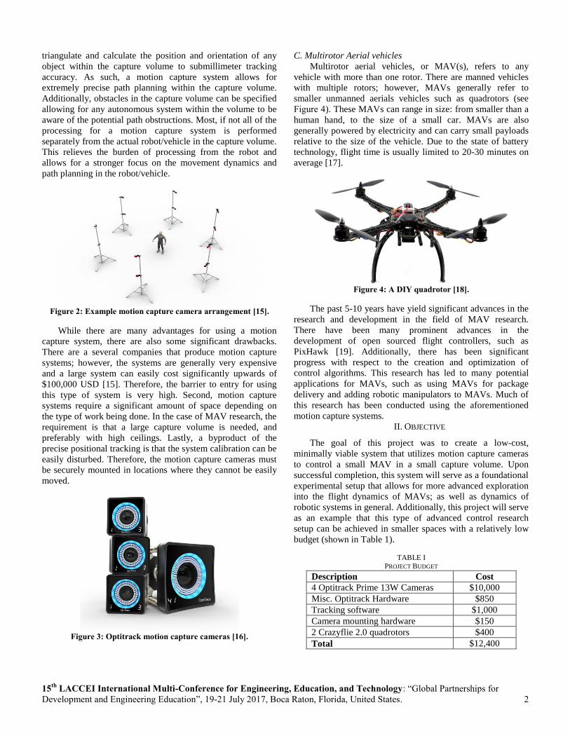
C. Multirotor Aerial vehicles
Multirotor aerial vehicles, or MAV(s), refers to any
vehicle with more than one rotor. There are manned vehicles
with multiple rotors; however, MAVs generally refer to
smaller unmanned aerials vehicles such as quadrotors (see
Figure 4). These MAVs can range in size: from smaller than a
human hand, to the size of a small car. MAVs are also
generally powered by electricity and can carry small payloads
relative to the size of the vehicle. Due to the state of battery
technology, flight time is usually limited to 20-30 minutes on
average [17].
Figure 4: A DIY quadrotor [18].
The past 5-10 years have yield significant advances in the
research and development in the field of MAV research.
There have been many prominent advances in the
development of open sourced flight controllers, such as
PixHawk [19]. Additionally, there has been significant
progress with respect to the creation and optimization of
control algorithms. This research has led to many potential
applications for MAVs, such as using MAVs for package
delivery and adding robotic manipulators to MAVs. Much of
this research has been conducted using the aforementioned
motion capture systems.
II. OBJECTIVE
The goal of this project was to create a low-cost,
minimally viable system that utilizes motion capture cameras
to control a small MAV in a small capture volume. Upon
successful completion, this system will serve as a foundational
experimental setup that allows for more advanced exploration
into the flight dynamics of MAVs; as well as dynamics of
robotic systems in general. Additionally, this project will serve
as an example that this type of advanced control research
setup can be achieved in smaller spaces with a relatively low
budget (shown in Table 1).
TABLE I
PROJECT BUDGET
Description Cost
4 Optitrack Prime 13W Cameras $10,000
Misc. Optitrack Hardware $850
Tracking software $1,000
Camera mounting hardware $150
2 Crazyflie 2.0 quadrotors $400
Total $12,400
15th
LACCEI International Multi-Conference for Engineering, Education, and Technology: “Global Partnerships for
Development and Engineering Education”, 19-21 July 2017, Boca Raton, Florida, United States. 3
Figure 5 shows a simplified process diagram of the
experimental system. The quadrotor has an onboard processor
that handles the basic flight controller. The ground system
consists of a desktop computer connected with the motion
capture system.
Figure 5: Motion capture process diagram.
III. EXPERIMENTAL SETUP
A. Motion Capture Space
There are many companies that provide motion capture
solutions; however most of them are extremely expensive.
Fortunately, Optitrack has several motion capture product
lines that are relatively affordable and support much of the
same functionality as the more expensive systems. Four of
Optitrack’s Prime 13W cameras were chosen for this project.
The Prime 13W has a resolution of 1.3 megapixels and can
achieve framerates up to 240 frames per second [16].
Additionally, the Prime 13W has a wide angle lens which is
helps to ensure maximum coverage of the capture volume.
The motion capture cameras were mounted on top of 10
foot telescoping poles in a square 10’x10’ arrangement. The
cameras were angled downwards to ensure maximum
overlapping camera view space. The cameras were powered
and connected to an Ethernet switch using power over
Ethernet (POE) cables creating a local Ethernet network
between cameras. The switch was then connected to the PC
using a single Ethernet cable.
Figure 6: Motion capture space in the ASRL.
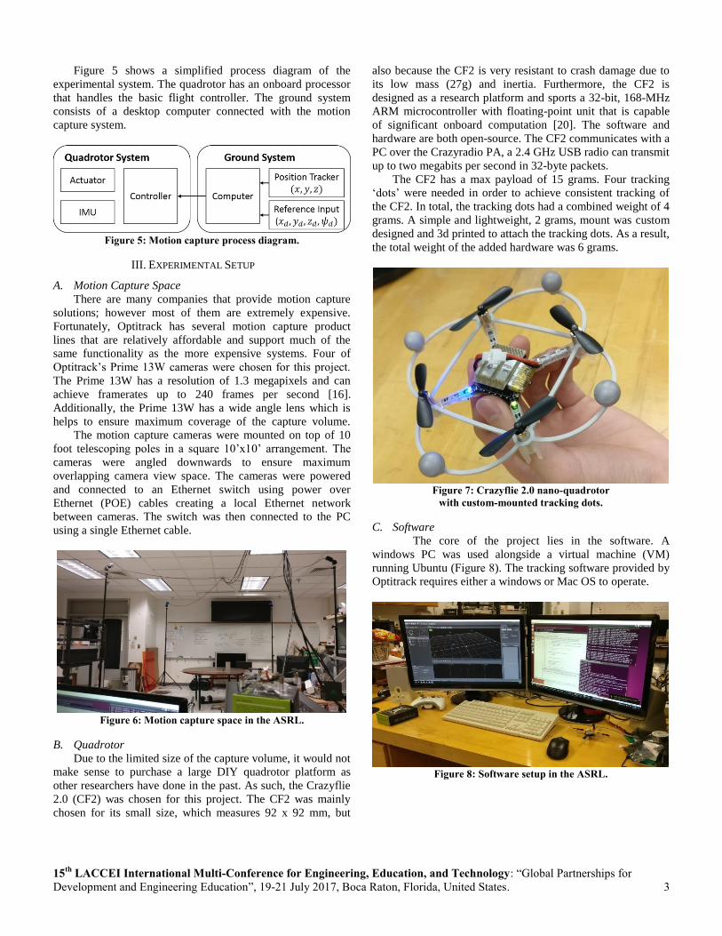
B. Quadrotor
Due to the limited size of the capture volume, it would not
make sense to purchase a large DIY quadrotor platform as
other researchers have done in the past. As such, the Crazyflie
2.0 (CF2) was chosen for this project. The CF2 was mainly
chosen for its small size, which measures 92 x 92 mm, but
also because the CF2 is very resistant to crash damage due to
its low mass (27g) and inertia. Furthermore, the CF2 is
designed as a research platform and sports a 32-bit, 168-MHz
ARM microcontroller with floating-point unit that is capable
of significant onboard computation [20]. The software and
hardware are both open-source. The CF2 communicates with a
PC over the Crazyradio PA, a 2.4 GHz USB radio can transmit
up to two megabits per second in 32-byte packets.
The CF2 has a max payload of 15 grams. Four tracking
‘dots’ were needed in order to achieve consistent tracking of
the CF2. In total, the tracking dots had a combined weight of 4
grams. A simple and lightweight, 2 grams, mount was custom
designed and 3d printed to attach the tracking dots. As a result,
the total weight of the added hardware was 6 grams.
Figure 7: Crazyflie 2.0 nano-quadrotor
with custom-mounted tracking dots.
C. Software
The core of the project lies in the software. A
windows PC was used alongside a virtual machine (VM)
running Ubuntu (Figure 8). The tracking software provided by
Optitrack requires either a windows or Mac OS to operate.
Figure 8: Software setup in the ASRL.

15th
LACCEI International Multi-Conference for Engineering, Education, and Technology: “Global Partnerships for
Development and Engineering Education”, 19-21 July 2017, Boca Raton, Florida, United States. 4
The tracking software captures and processes different
objects denoted by different sets of spherical markers to create
a list of rigid body data. This data is then streamed from the
windows partition into the Ubuntu VM. At this point, the data
is received and processed by the robot operating system or
ROS. A custom in-house script was written to depacketize and
convert the rigid body data into a usable coordinate system for
ROS. Then the data was sent to a ROS sub-package,
MAVROS, a software package specifically written to handle
communication for MAVs. Once the MAVROS receives the
data, it is then wireless sent to the quadrotor over a local wifi
network.
IV. QUADROTOR DYNAMICS
Quadrotors have four fixed pitch-angle blades, whereas
class helicopters have variable-pitch-angle blades. The control
of a quadrotor is performed by varying the speed of each rotor.
A concept of the quadrotor is shown in Figure 9 [21].
Figure 9: Quadrotor Model
The dynamic equations of the quadrotor model may be
derived from a Lagrange approach, and is simplified as
follows (Eqns. 1-6):
�̈� = 𝑢1(cos 𝜙𝑠𝑖𝑛𝜃 cos 𝜓 + 𝑠𝑖𝑛𝜙𝑠𝑖𝑛𝜓) (1)
�̈� = 𝑢1(cos 𝜙𝑠𝑖𝑛𝜃 cos 𝜓 − 𝑠𝑖𝑛𝜙𝑠𝑖𝑛𝜓) (2)
�̈� = 𝑢1(cos 𝜙𝑐𝑜𝑠𝜃) − 𝑔 (3)
�̈� = 𝑢2𝑙 (4)
�̈� = 𝑢3𝑙 (5)
�̈� = 𝑢4 (6)
where [x, y, z] are positions of the quadrotor in the inertial
frame; [φ, θ, ψ] Euler angles represent roll, pitch, and yaw
angles, respectively; and g the acceleration of gravity: and 𝑙 is
the length between the center of the quadrotor and the rotor.
The control inputs u1, u2, u3, u4 are defined as follows (Eqns.
7-10):
𝑢1 =1
𝑚(𝑇1 + 𝑇2 + 𝑇3 + 𝑇4) (7)
𝑢2 =1
𝐽1(𝑇2 − 𝑇4) (8)
𝑢3 =1
𝐽2(−𝑇1 + 𝑇3) (9)
𝑢4 =𝐶
𝐽3(𝑇1 − 𝑇2 + 𝑇3 − 𝑇4) (10)
where 𝑢1 is the normalized total lift force, and 𝑢2, 𝑢3, and 𝑢4
correspond to the control inputs of roll, pitch, and yaw
moments, respectively; 𝐽𝑖 (𝑖 = 1,2,3) is the moments of inertia
with respect to the axes; and C is the force-to-moment scaling
factor
V. PD CONTROLLER
Since the quadrotor is as under-actuated system which has
six state variables and four control inputs, two states, x and y,
are not controlled directly. Hence, the desired pitch and roll
angles to control x and y using desired x and y as follows
(Eqns. 11 and 12) [22]:
𝜙𝑑 = 𝑠𝑖𝑛𝜓(𝛼�̇�𝑥 − 𝛽�̇�𝑥) − 𝑐𝑜𝑠𝜓(𝛼�̇�𝑦 + 𝛽�̇�𝑦) (11)
𝜃𝑑 = 𝑐𝑜𝑠𝜓(𝛼�̇�𝑥 + 𝛽�̇�𝑥) + 𝑠𝑖𝑛𝜓(𝛼�̇�𝑦 + 𝛽�̇�𝑦) (12)
where 𝛼 and 𝛽 are constant values, 𝑒�̇� = �̇�𝑑 − �̇�, 𝑒𝑥 = 𝑥𝑑 − 𝑥,
𝑒�̇� = 𝑦𝑑 − �̇� , 𝑒𝑦 = 𝑦𝑑 − 𝑦 . Through these equations, x-y
plane motion can be controlled using 𝑢2 and 𝑢3 with 𝜙𝑑 and
𝜃𝑑. In addition, 𝑢1 and 𝑢4 can be defined to control the z and
𝜓 states directly. As a result, the PD controller of the
quadrotor can be written as follows (Eqns. 13-16):
𝑢1 = 𝑘𝑝,𝑧(𝑧𝑑 − 𝑧) + 𝑘𝑑,𝑧(�̇�𝑑 − �̇�) + 𝑔 (13)
𝑢2 = 𝑘𝑝,𝜙(𝜙𝑑 − 𝜙) + 𝑘𝑑,𝜙(�̇�𝑑 − �̇�) (14)
𝑢3 = 𝑘𝑝,𝜃(𝜃𝑑 − 𝜃) + 𝑘𝑑,𝜃(�̇�𝑑 − �̇�) (15)
𝑢4 = 𝑘𝑝,𝜓(𝜓𝑑 − 𝜓) + 𝑘𝑑,𝜓(�̇�𝑑 − �̇�) (16)
where 𝑘𝑝 and 𝑘𝑑 are proportional and derivative gains,
respectively.
VI. PRELIMINARY DATA
As of now, the project is nearing 90 percent completion.
At this point, the motion capture system has been setup and
calibrated. Figure 10 shows the motion capture tracking
interface using multiple cameras to triangulate the position of
a tracked object. The motion capture cameras are represented
as floating blue triangular prisms.

15th
LACCEI International Multi-Conference for Engineering, Education, and Technology: “Global Partnerships for
Development and Engineering Education”, 19-21 July 2017, Boca Raton, Florida, United States. 5
Figure 10: Motion capture tracking interface.
The motion capture software is capable of recording the
position of tracked objects. Figure 11 shows a sample
recording of a quadcopter flying in a circle and then
subsequently landing.
Figure 11: Sample positional tracking data obtained from
preliminary test flights.
Motion capture system aside, the quadcopter has been
flashed with the appropriate firmware. The tracking software
streams the tracking data from Windows into Linux and ROS.
A custom program was written to send target set points for the
quadcopter to fly to and hold at using local position
estimators. Furthermore, a script was created to handle the
remote arming/disarming of the quadrotor (in case of
emergency). Unfortunately, there have been issues with the
wireless communication with the quadrotor. However, we
believe that this can be resolved by switching from the radio
transmitter over to a local wireless network instead.
VII. FUTURE WORK
We intend to resolve the communication issues we are
having at present and then begin testing basic positional
control programs. Upon successful completion of the basic
tests, we will begin exploring different quadrotor control
algorithms, path planning, and world exploration techniques.
Furthermore, we will begin development on a more
customizable DIY quadrotor frame, as opposed to using an off
the shelf solution, in order to explore possibilities such as
attaching companion robots and sensors to a quadrotor. This
paper serves as a basic introductory guide for researchers
interested in developing a low-cost, low-space tracking system
for MAVs.
VIII. ACKNOWLEDGEMENTS
UMBC Mechanical Engineering Department
Autonomous Systems Research Laboratory (ASRL)
LSAMP Bridge to the Doctorate Fellowship
REFERENCES
[1] R. Garcia, "Guaranteed quadrotor position estimation
based on GPS refreshing measurements," IFAC, vol. 28,
no. 9, pp. 67-72, 2015.

15th
LACCEI International Multi-Conference for Engineering, Education, and Technology: “Global Partnerships for
Development and Engineering Education”, 19-21 July 2017, Boca Raton, Florida, United States. 6
[2] Z. Xu, "Autonomous Flight Control of a Nano Quadrotor
Helicopter in a GPS-Denied Environment Using On-
Board Vision," IEEE Transactions on Industrial
Electronics, vol. 62, no. 10, pp. 6395-6403, 2015.
[3] X.-Z. Peng, "Path planning and obstacle avoidance for
vision guided quadrotor UAV navigation," in IEEE
International Conference on Control and Automation,
2016.
[4] N. Xie, "Position estimation and control for quadrotor
using optical flow and GPS sensors," in Youth Academic
Annual Conference of Chinese Association of
Automation, 2017.
[5] A. Smith, "Low cost alternative to motion capture
systems for indoor flight testing using on-board computer
vision," in Atmospheric Flight Mechanics Conference,
2016.
[6] L. Gomes, "Unmanned quadcopter control using a motion
capture system," IEEE Latin America Transactions, vol.
14, no. 8, pp. 3606-3613, 2016.
[7] J. Troy, "Haptics-enabled UAV teleoperation using
motion capture systems," Journal of Computing and
Information Science in Engineering, vol. 9, no. 1, pp. 1-7,
2009.
[8] J. Troy, "Closed-loop motion capture feedback control of
small-scale aerial vehicles," in AIAA InfoTech at
Aerospace Conference, 2007.
[9] indoorFPV, "Choosing the Right RC Transmitter Radio
for Quadcopter," indoorFPV, 2015.
[10] D. Mellinger, "Recent advances in quadrotor
capabilities," in IEEE International Conference on
Robotics and Automation, 2011.
[11] D. Mellinger, "Control of quadrotors for robust perching
and landing," in International Powered Lift Conference
2010, 2010.
[12] H. Lim, "Onboard flight control of a micro quadrotor
using single strapdown optical flow sensor," in IEEE
International Conference on Intelligent Robots and
Systems, 2012.
[13] M. Faessler, "Autonomous, Vision-based Flight and Live
Dense 3D Mapping with a Quadrotor Micro Aerial
Vehicle," Journal of Field Robotics, vol. 33, no. 4, pp.
431-450, 2016.
[14] S. Roelofsen, "Reciprocal collision avoidance for
quadrotors using on-board visual detection," in IEEE
International Conference on Intelligent Robots and
Systems, Hamburg, 2015.
[15] Optitrack, "Build your system," Optitrack, 2017.
[16] Optitrack, "Prime 13W," Optitrack, 2017.
[17] D. James, "Drone with the best flight times,"
DronesGlibe, [Online]. Available:
http://www.dronesglobe.com/guide/long-flight-time/.
[Accessed 6 4 2017].
[18] S. R. Hobby, "550mm RTF Quadcopter UAV,"
Robotshop, 2017.
[19] Pixhawk, "PX4 Autopilot," 2017.
[20] Bitcraze, "Crazyflie 2.0," bitcraze, 2017.
[21] J. Goodman, J. Kim, S. Wilkerson and S. A. Gadsden,
"Mathematical Modeling and System Identification of an
Unmanned Aerial System," in 2015 SPIE Unmanned
Systems Technology XXVII, Baltimore, 2015.
[22] J. Kim, S. Wilkerson and A. Gadsden, "Comparison of
Gradient Methods for Gain Tuning of a PD Controller
Applied on a Quadrotor System," in 2016 SPIE
Unmanned Systems Technology XVIII, Baltimore, 2016.
[23] N. Michael, "The GRASP multiple micro-UAV testbed,"
IEEE Robotics and Automation Magazine, vol. 17, no. 3,
pp. 56-65, 2010.
[24] X. Wei, "Autonomous control system for the quadrotor
unmanned aerial vehicle," in International Conference on
Ubiquitous Robots and Ambient Intelligence, 2016.