motion signalling solutions for cycling jacket
TRANSCRIPT
Material Science. Textile and Clothing Technology
_______________________________________________________________________________________________2012 / 7
57
Motion Signalling Solutions for Cycling Jacket Marianna Grecka1, Ausma Vilumsone2, Juris Blums3, 1-3Riga Technical University,
Zane Pavare4, 4 Riga Stradina University
Abstract – The prototype of cycling belt has been drawn up with LED stop signals, which are activated by the accelerometer placed in the central back pocket. The results of approbation have shown that the sensor does not provide the proper functioning of signals, due to a high level of riding movements.
Using Motion Capture technology and bicycle exercise equipment, the research of oscillation of anthropometric points on the back has been carried out. The accelerometer should be placed between scapulae to design the cycling jacket.
Furthermore, the research of choice and integration of light emissive elements has been carried out.
Keywords – accelerometer, motion capture, wearable
electronics.
I. INTRODUCTION
Due to a fast-rising number of cyclists, the safety problems of cyclists become topical [1]. The cyclist’s visibility can remarkably be improved by integrating not only the light reflective, but also light emissive elements (LEDs, electroluminescent strips and wires) in the cycling suit (Fig. 1).
a b c Fig. 1. Light emissive elements in the cycling suit: a – a belt with LED text [2], b – a bicycle helmet with EL wire [3], c – a cycling sash with EL strips [4]
The prototype of cycling belt (Fig. 2) with pockets and light emissive elements has been developed within the framework of the present research. The principle of the belt – while the cyclist rides at a constant speed or is at rest state , the LEDs flash, but when the cyclist is braking the LEDs light up instantly (like brake lights), which are activated by a signal coming from the sensor (accelerometer), placed in the central back pocket (Fig. 3).
Fig. 2. Front and back of cycling belt
The approbation has proven that the sensor (placed on the back of the belt) does not provide the proper functioning of stop signals, due to the high level of additional movements of a cyclist during the riding. In this case, it is unacceptable.
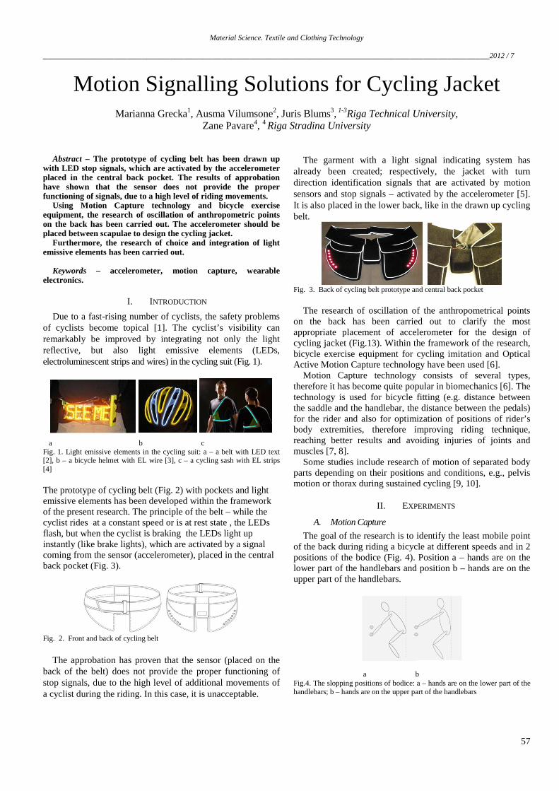
The garment with a light signal indicating system has already been created; respectively, the jacket with turn direction identification signals that are activated by motion sensors and stop signals – activated by the accelerometer [5]. It is also placed in the lower back, like in the drawn up cycling belt.
Fig. 3. Back of cycling belt prototype and central back pocket
The research of oscillation of the anthropometrical points on the back has been carried out to clarify the most appropriate placement of accelerometer for the design of cycling jacket (Fig.13). Within the framework of the research, bicycle exercise equipment for cycling imitation and Optical Active Motion Capture technology have been used [6].
Motion Capture technology consists of several types, therefore it has become quite popular in biomechanics [6]. The technology is used for bicycle fitting (e.g. distance between the saddle and the handlebar, the distance between the pedals) for the rider and also for optimization of positions of rider’s body extremities, therefore improving riding technique, reaching better results and avoiding injuries of joints and muscles [7, 8].
Some studies include research of motion of separated body parts depending on their positions and conditions, e.g., pelvis motion or thorax during sustained cycling [9, 10].
II. EXPERIMENTS
A. Motion Capture
The goal of the research is to identify the least mobile point of the back during riding a bicycle at different speeds and in 2 positions of the bodice (Fig. 4). Position a – hands are on the lower part of the handlebars and position b – hands are on the upper part of the handlebars.
a b Fig.4. The slopping positions of bodice: a – hands are on the lower part of the handlebars; b – hands are on the upper part of the handlebars

Material Science. Textile and Clothing Technology
2012 / 7_________________________________________________________________________________________________
58
The motion capture technology has been used in the study. The digital cameras of the installed system record the movement of anatomical points in 3 dimensions [11]. To record the motion, markers (small spheres, which are detected with infrared cameras) have been placed and attached to human anatomical points of the body (Table 1).
Six infrared light cameras send an infrared beam (120 Hz) and detect reflection of spherical markers (Fig. 5). The motion trajectories of the back points in 3 dimensions have been registered, and coordinates in time of reflective markers have been calculated.
1. Infrared rays 2. Reflection 3. Transmission of coordinates to a computer 4. Human body under characterization 5. Computer 6. Camera
Fig.5. Placement of cameras according to the human body and principle of action of the system
B. Stages of Experiment
14 infrared ray reflective markers have been attached to definite points (Table I) of the back (Fig. 6). The points have been marked with numbers and letters according to the points, which are used in construction of clothing.
a b Fig.6. Placement of the markers; axis of coordinates and markers in real (a) and virtual (b) environment
TABLE I
MARKING AND EXPLANATION OF MARKERS
No. Markers Placement of the point 1. 12, 12A Shoulder part of scapula 2. 121, 121A Upper corner of scapula 3. 11 Cervical vertebra c7 4. 22, 22A Lower edge of scapula 5. 21 Thoracic vertebra t3 6. 41 Lumbar vertebra I2 7. 43, 43A Edge of ilium on the middle line of armpit 8. 42, 42A Edge of Ilium on the line of scapula 9. 51 The middle point of sacrum
Cycling equipment has been prepared for the experiment:
the height of the saddle and handlebars have been regulated
according to the parameters of the human body. The load of pedalling has been adjusted and test ‘rides’ have been made.
Eight experimental ‘rides’ have been made at different speeds and in two slopping positions (A and B) of the body. Each ‘ride’ lasted 10 seconds. Conditions of the experiment can be seen in Table II.
TABLE II
CONDITIONS OF THE EXPERIMENT WITH CYCLING EQUIPMENT
No. Position Speed, km/h Time, s 1. A 15 10 2. A 20 10 3. A 25 10 4. A increasing from 15 to 30 10 5. B 15 10 6. B 20 10 7. B 25 10 8. B increasing from 15 to 30 10
Using special software and cameras, each coordinate in
time of the markers has automatically been registered and calculated, and visualized on the monitor of the computer (Fig. 6, b).
C. Data Processing
During the experiment it has been noticed that markers 42, 43, 42A, 43A, placed on the lower part of the back, have greater amplitude of motion than other markers. Therefore, these points have been excluded from the further calculations.
Total amplitude of acceleration of each marker (2) has been clarified, when minimal and maximal values of total acceleration have been identified.
The component of acceleration (1) of motion point in the definite direction is the derivation of component of speed, or the second derivation of corresponding coordinate [12]:
, (1)
where ax–x component of the acceleration;
ay– y component of the acceleration; az– z component of the acceleration; t –time (s); vx– x component of the velocity; vy– y component of the velocity; vz– z component of the velocity.
Absolute value of acceleration is:
, (2) where atotal – the module of total acceleration.
Table III presents the calculation of total acceleration of marker with code 12, increasing speed from 15 to 30 (km/h).

Material Science. Textile and Clothing Technology
_______________________________________________________________________________________________2012 / 7
59
TABLE III
THE CALCULATION OF TOTAL ACCELERATION OF MARKER 12 (INCREASING SPEED FROM 15 TO 30 KM/H)
No. x, cm vx, m/s ax, m/s2 y, cm vy, m/s ay , m/s2 z, cm vz, m/s az, m/s2 v, m/s atotal, m/s2
1. 20.79 0.31 -0.26 352.32 -0.03 -0.001 1397.75 0.09 0.01 0.32 0.26
… … … … … … … … … … … …
2400. 5.27 -0.52 0.21 340.21 -0.25 0.04 1399.49 0.14 0.04 0.59 0.22
min -0.90 -1.58 -1.41 0.002
max 0.92 1.58 1.24 2.14
min - max 1.82 3.16 2.65 2.14
III. RESULTS
The lowest amplitude of acceleration in position A (Fig. 7) at different speeds is characteristic of markers 22, 22A, 21, but the largest – of markers 121, 121A, 12A.
Fig. 7. Amplitude of total acceleration of markers in position A
The lowest amplitude of acceleration in position B (Fig. 8) at different speeds is characteristic of markers 11, 22, 22A, but the largest – of markers 12, 12A, 21,51.
Fig. 8. Amplitude of total acceleration of markers in position B
Special attention has been paid to values of y axis coordinates and acceleration, as an axis with riding/braking direction. This data is important for programming and regulating the accelerometer. The lowest amplitude of acceleration in positions A and B at different speeds is characteristic of markers 22, 22A, 21 and 11 (Fig. 9, Fig. 10).
Fig. 9. Amplitude of total acceleration of axis y markers, in position A
Fig. 10. Amplitude of total acceleration of axis y markers, in position B
IV. LIGHT EMISSIVE ELEMENTS
A. The Choice of Elements
Electroluminescent (EL) wire (Fig. 11) or optical wire has been designed to be integrated in the cycling jacket. Due to a small diameter and flexibility, these wires can be sewn up with a sewing machine or hand stitched. Despite these features, EL wire has been replaced with SMD (surface mount diode) strip. Firstly, it is better seen in the daytime and at night than the above-mentioned wire. A small difference is observed between switched on and switched off mode of EL wire in the daytime (Fig. 11). Secondly, the plain, flexible and isolated strip of surface mount diodes contains all necessary electronic components. Thirdly, connecting wires can be soldered to the ends of strip or in the middle part of strip. This process eases the integration of connecting wires in the construction seams of the jacket.
a b c Fig. 11. Comparison of EL wire modes: in the daytime switched off (a) and switched on (b); at night switched on (c)
B. Integration of Light Emissive Elements
For the integration of SMD strip, special tunnels (Fig. 13, b, Fig. 12, c) of the lower and upper parts have been designed. The lower part – fabric of the jacket and the upper part – transparent, braided or weaved ribbon or ribbons of synthetic fibres with width of 3.5 cm, in red or yellow colour (Fig. 12, a, b).

Material Science. Textile and Clothing Technology
2012 / 7_________________________________________________________________________________________________
60
a b c Fig. 12. Red (a) and yellow (b) braided ribbon; SMD strip placed in the special made tunnel of ribbons (c)
a b
Fig. 13. Front of cycling jacket (a) and the designed tunnel with SMD strip integration in the jacket (b)
The main functions of the ribbons are the following: to be the component of tunnel and to disperse the light coming from the SMD strip inserted in the tunnel.
The goal of this part of the research has been to define the type and number of layers of ribbon for better light dispersion and for protection against the eyes to be dazed, using bright red and yellow SMD strips.
C. Experiment
To conduct the experiment, it has been necessary to use one red and one yellow SMD strip, three types of synthetic ribbons, dark (black) fabric for background and camera for taking photos.
The ribbons with code numbers shown in Table IV have been attached to the black background thereby making a tunnel, where a red or yellow SMD strip has been inserted and photos taken.
TABLE IV
CODING AND EXPLANATION OF RIBBONS
Code number of ribbon Structure Colour of ribbon
1 Braided Red
2 Braided Yellow
3 Weaved Red
The tunnels have been made of single, double and triple
layers of ribbons; for example, code number 1 means one layer of ribbon, 11 means two layers on the same ribbon. Table V shows the photos (without flash) taken in dark using the same configuration of settings of the camera.
Comparing the photos, it is obvious that the light is better dispersed using triple layered tunnels and corresponding colour. It means that the light is better dispersed, when yellow SMD strip light is covered with triple layers of yellow ribbon, and similarly when a red light is covered with red layers of ribbon.
SMD spot of lights, which are covered with three layers of braided ribbon, appears in square shape (see Table 5, row 3, 6). It is caused by the fact that the yarns of braided ribbon are positioned at an angle of 45 degrees to the horizontal. But those that are covered with weaved ribbon appear in the shape of circle (Table V, row 9, 10). The reason is that the yarns are positioned at an angle of 90 degrees to the horizontal.
TABLE V
CODING AND EXPLANATION OF RIBBONS
No. Code of
ribbon
SMD strip Red Yellow
1. 1
2. 11
3. 111
4. 2
5. 22
6. 222
7. 3
8. 33
9. 333
10. 312
DISCUSSION AND CONCLUSIONS
The goal of the study has been to detect the points of the back, whose periodical motions, during the pedalling, minimally influence the readouts of accelerometer and allow them, without disturbances, to define the changes in speed in the riding direction of bicycle. Experimental researches demonstrate that the motion dynamics of markers depends on the position of the bodice and riding speed. It’s proved with marker 21 (amplitude of total acceleration and amplitude of total acceleration of axis y), small oscillations in position A, increased – in position B (Fig. 7, Fig. 8). Therefore, the most suitable place for accelerometer is the body point 21 or 11, or between them.

Material Science. Textile and Clothing Technology
_______________________________________________________________________________________________2012 / 7
61
From the point of view of the clothing construction these points are acceptable, as they can be placed on the back central seam. The sensor can be easily integrated, placing it on seam allowances (sensor parameters 10 x 15 x 2 mm). The detail (-s) of clothing upper part of the back is less influenced by deformation (Fig. 14).
In terms of safety, considering anthropometric features, the sensor at this place (marker 21) is less influenced mechanically, as there is concavity between scapulae. For example, putting on a rucksack, the sensor will not be damaged.
Red and yellow SMD strips have been chosen for integration as light-emissive elements because of their brightness and flexibility of connection with wires.
To disperse bright light of diodes and facilitate the integration of light strips, special tunnels have been made with dispersion layers of ribbons. Triple layered tunnel disperse light better than double and single layered tunnels.
Depending on the density and position of yarns in the ribbons, the light disperses in the shape of a square or circle.
Fig. 14 demostrates the draw up cycling jacket with yellow turn direction signals and red stop signals, activated by the accelerometer.
Fig. 14. Front and back of the cycling jacket
REFERENCES 1. Buehler, R.: Cycling for a Few or for Everyone: The Importance of
Social Justice in Cycling Policy, World Transport Policy and Practice, Vol. 15 (May 2009), No. 1., pp. 57-64
2. Y. Fritz, “Cyclelicious”, August 2009. [Online]. Available: http://www.cyclelicio.us/2009/08/see-me-light-belt.html [Accessed: Nov. 2, 2010].
3. Enlighted (author), “Instructables”, How to add EL wire to a coat or other garment, June, 2008. [Online]. Available: www.instructables.com/id/how-to-add-EL-wire-to-a-coat-or-other-garment/step10/other-examples-EL-wire-hats-and-helmets/ [Accessed: Feb. 5, 2011].
4. Exelite media, photos, 2007. [Online]. Available: http://www.exelitesafety.com/media.html [Accessed: Nov. 2, 2010].
5. Free Patents Online, IP Research and Communities, 2012.[Online].Available: http://www.freepatentsonline.com/20100251453.pdf [Accessed: Apr. 15, 2011].
6. J. Lee, “Home page – professor Jehee Lee, courses, April, 2011. [Online]. Available: http://mrl.snu.ac.kr/courses/CourseAnimation/notes/MotionCapture.pdf [Accessed: Sep. 15, 2012].
7. Retul, Retul Fit Technology, 2012. [Online]. Available: http://retul.com/about-retul.asp [Accessed: Sep. 15, 2012].
8. Fitwerx, The future of bike fitting, 2011. [Online]. Available: http://www.fitwerx.com/motion-capture-analysis [Accessed: Sep.15, 2012].
9. J. Sauer, J. Potter, C. Weisshaar, etc., “Influence of gender, power, and hand position on pelvic motion during seated cycling”, Medicine and Science in Sports and Exercise, volume 39, issue 12, pages 2204-2211, December 2007. [Online]. Available: Scopus, http://www-scopus-com.resursi.rtu.lv/home.url. [Accessed September 15, 2012].
10. M. Sayers, A. Tweddle, “Thorax and pelvis kinematics change during sustained cycling”, International Journal of Sports Medicine, volume 33, issue 4, pages 314-319, 2012. [Online]. Available: Scopus, http://www-scopus-com.resursi.rtu.lv/home.url. [Accessed September 15, 2012].
11. Dabolina, I. Vilumsone, A. Fjodorovs, A.: Application of Non-Contact 3D Positioning for Anthropometrical Modelling, Scientific Journal of RTU, vol. 4 (2009), pp. 138-145
12. Apinis, A., Fizika, Zvaigzne, Rīga (1972)
ACKNOWLEDGEMENTS
This work has been supported by the European Social Fund within the project “Establishment of interdisciplinary research groups for a new functional properties of smart textiles development and integrating in innovative products”, No. 2009/0198/1DP/1.1.1.2.0./09/APIA/VIAA/148.
Marianna Grecka, MSc.ing., doctoral student. She received a Professional Bachelor Degree in Material Technology and Design in 2010 from Riga Technical University and received a Professional Master Degree in Clothing and Textile Technology in 2012 from Riga Technical University. The title of thesis is “Projection of Functional Clothing”. Since 2011 she has been working as a Researcher at Riga Technical, University, Institute of Textile Materials Technologies and Design. Field of research – integration of electronics in the smart textiles. E-mail: [email protected] Ausma Vilumsone, Dr.sc.ing., Professor, (1993) at RTU, Institute of Textile Materials Technologies and Design,. She is the Head of the Institute of Textile Materials Technologies and Design, Head of the Department of Clothing and Textile Technologies. Fields of research: development and optimization of garment design technological process, CAD/CAM systems in product design, innovative materials and technologies. E-mail: [email protected] Juris Blums, Dr.phys., Associate Professor. He graduated from the University of Latvia in 1992, obtained Dr.phys. in 1997 from the University of Latvia, the title of thesis “Laser Induced Centers in Silicon”. J.Blums was a guest scientist at Tallinn Technical University (Estonia, 2000), University of Essen (Germany, 2001–2003) in experimental physics. Since 2003 he has been working as an Associate Professor at Riga Technical University, Institute of Technical Physics. Fields of scientific interests: semiconductor physics, laser-matter interaction, solar batteries. E-mail: [email protected] Zane Pavare, Dr. med., Associate Professor. She graduated from RMI in 1979, obtained Dr. med. in 1991 from the Latvian Research Institute of Traumatology and Orthopedics. Since 2006 she has been working as a Leading Researcher at the Faculty of Rehabilitation, RSU. Z. Pavare was a guest doctor at Gillette Children’s Specialty Healthcare in St. Paul (MN,USA, 2008) and Evangelisches Waldkrankenhaus Spandau in Berlin (Germany, 2006), Fields of scientific interests: gait and movement analysis. E-mail: [email protected]
INVESTING IN YOUR FUTURE

Material Science. Textile and Clothing Technology
2012 / 7_________________________________________________________________________________________________
62
Marianna Grecka, Ausma Viļumsone, Juris Blūms, Zane Pavāre. Kustību signalizēšanas risinājumi velobraucēja jakā Līdz ar velosipēdistu skaita palielināšanos, rodas nepieciešamība palielināt drošību aktīvajā satiksmes plūsmā. To iespējams risināt, integrējot gaismu izstarojošos un atstarojošos elementus velobraucēja apģērbā. Iepriekšējos pētījumos tika izveidota josta ar LED, kas signalizē par velobraucēja apstāšanos, ko nodrošina mugurdaļā esošā sensora (akselerometra) signāls. Aprobējot jostu, konstatēts, ka sensora darbību traucē muguras lejasdaļas kustības, kas rodas braucot ar velosipēdu. Projektējot velobraucēja jaku ar līdzīgām funkcijām, tika veikts velosipēdista muguras punktu svārstību pētījums, lai noskaidrotu vismazkustīgāko muguras punktu braukšanas laikā. Izmantots velotrenažieris (braukšanas imitācijai) un motion capture tehnoloģija, ar kuru tika fiksētas un aprēķinātas uz muguras izvietoto marķieru koordinātes laikā. Nosakot sensora izvietošanas vietu, secināts, ka atzīmēto ķermeņa punktu kustības dinamika ir atkarīga no cilvēka stāva noliekšanās pozīcijas un braukšanas ātruma. Vismazākās svārstības raksturīgas muguras punktiem, kas atrodas lāpstiņu līmenī, līdz ar to paātrinājuma sensors velobraucēja jakā ir jāizvieto posmā no mugurkaula kakla septītā un krūšu trešā skriemeļa. Risinot gaismu izstarojošo elementu integrēšanas iespējas velobraucēja jakā, elektroluminiscento un optisko vadu vietā tika izmantots sarkanas un dzeltenas SMD (surface mount diode) gaismas joslas, jo tās ir spilgtākas un ērtāk savienojamas ar vadiem. Izstrādāts SMD joslu integrēšanas veids. Sākuma stadijas integrēšana paredz tekstilmateriāla tuneļa izgatavošanu, kas sastāv no apakšdaļas (pamatdrāna) un virsdaļas (caurspīdīga sarkana, dzeltena pīta vai austa lente). Lai noskaidrotu tuneļa virsdaļas materiāla izkliedes īpašības, izpētītas 3 veidu lenšu gaismas izkliedes īpašības, variējot slāņu skaitu, savstarpēju kombināciju. Noskaidrots, ka labāk gaisma tiek izkliedēta zem 3 lenšu slāņiem, uz gaismas avota novietojot tās pašas krāsas lentes (sarkana gaisma pārklāta ar sarkanām lentēm). Lentes pavedienu savstarpējs novietojums nosaka gaismas izkliedes formu – zem pītās lentes gaisma izkliedējas kvadrāta formā, zem austas – apļa formā. Марианна Грецка, Аусма Вилюмсоне, Юрис Блумс, Зане Паваре. Решение сигнализации движений для куртки велосипедиста С увеличением числа велосипедистов возникают вопросы их безопасности в активном потоке транспортного движения. Это возможно решить с помощью интегрирования светоизлучающих и светоотражающих элементов в одежду велосипедистов. В предыдущих исследованиях был создан пояс с LED элементами, сигнализирующими при торможении велосипеда. Эту функцию обеспечивает сигнал сзади находящегося сенсора (акселерометра). Во время апробации пояса констатировано, что движения нижней части спины во время езды на велосипеде создают помехи для действия сенсора. Проектируя куртку с похожими функциями, было исследовано колебание различных точек спины велосипедиста, с целью выяснить наименее подвижную точку на спине во время езды на велосипеде. Был использован велотренажер (для имитации езды) и технология motion capture, с помощью которой зафиксированы и произведены расчеты координат маркеров размещенных на спине. Определив расположение сенсора на спине, констатировали, что двигательная динамика отмеченных точек на спине зависит от наклона торса человека и скорости езды. Наименьшие колебания маркеров отмечались в точках на уровне лопаток. Следовательно, сенсор ускорения оптимально разместить между седьмым шейным и третьим грудным позвонками. Исследовав возможности интегрирования в куртку светоизлучающих элементов, вместо электролюминeсцирующего и оптического провода были использованы легко соединяемые с проводами и более яркие светодиодные полосы SMD (surface mount diode) красного и желтого цвета. Разработан способ интегрирования в одежду световых полос SMD. В начальной стадии интегрирования диодных полос предполагает создание туннеля из текстильных материалов. Нижней частей является основное полотно, а верхней - прозрачная красная, желтая плетеная или тканая лента. Чтобы выяснить рассеивание света сквозь материал верхней части туннеля, во время исследований были использованы 3 вида лент с различными свойствами рассеивания света, а также меняя количество слоев лент и их комбинацию. Выяснено, что самое оптимальное рассеивание света создают 3 слоя лент, идентичного с диодами цвета (красный свет под красными лентами).Форму рассеянного света определяет расположение нитей ленты. Под плетеной лентой рассеивается в форме квадрата, а под тканой – в форме круга.