motion study of a wheelchair prototype for disabled peopleimtuoradea.ro/auo.fmte/files-2015-v1/ionut...
TRANSCRIPT

Abstract— In this paper is presented the design and
experimental prototype of a wheelchair for disabled people.
Design solution proposed to be implemented uses two
reduction gears motors and a mechanical transmission with
chains. The motion controller developed uses PWM technology
(pulse wave modulation). The wheelchair has the ability of
forward – backward motion and steering. The design solution is
developed in Solid Works, and it’s implemented to a
wheelchair prototype model. Wheelchair design and motion
makes him suitable especially for indoor use. It is made a study
of the wheelchair kinematics, first using a kinematic simulation
in Adams. Are presented the wheelchair motion trajectory and
kinematics parameters. The experimental prototype is tested
with a motion analysis system based on ultra high speed video
recording. The obtained results from simulation and
experimentally tests, demonstrate the efficiency of wheelchair
proposed solution.
Keywords—Wheelchair, kinematics, prototype, motion
study.
I. INTRODUCTION
HIS paper is structured in three sections. The
introduction section presents a literature review of
existing wheelchairs design solutions. The second part
presents the design solution of experimental prototype
and motion controller implemented to the wheelchair. In
the last part is presented the kinematical characterization
of the wheelchair, by motion simulation in Adams and
experimental motion analysis. The experimental motion
analysis is based on high speed cameras motion capture
and analysis equipment.
To assist mobility of disabled persons, several
electrical powered wheelchairs are available on the
market [1]-[4]. In last decades, there have been great’s
improvements in power wheelchairs design and
manufacture. Wheelchairs available on the market, for
disabled patients, are much diversified as features and
facilities, allowing the user to adjust their sitting position.
Power wheelchairs are used predominantly by people
with both lower and upper extremity impairment resulting
from cerebral palsy, high-level spinal cord injury, or
muscular dystrophy [5]. The propulsion system of
powered wheelchairs typically consists of a pair of
motors, one for each drive wheel, and a drive train
consisting of gears, belts and other mechanical elements
that couples the motor’s shaft to the drive wheel shaft.
Speed and torque generated by each motor is controlled
by modulating the pulse width. Solid state relays are
generally used to switch supply voltage polarity to
change the running direction of PM (permanent magnet)
motors [6]-[7]. The wheelchair’s control module converts
positional information from the joystick into power
signals to the motors. Control modules are
microprocessor based and have many adjustable
parameters. Many control modules utilize feedback to
sense whether the motor is responding properly to the
joystick position. Such control systems adjust motor
torque so as to maintain near constant speed while the
load varies in response to changes in the terrain (incline,
bumps) and surface (linoleum, carpeting, concrete, grass,
sand) [8]-[12].
Proposed solution uses an indirect drive transfer
system, the motor is coupled to the drive wheel shaft
through a system of gear train and flexible machine
element (chains). The gear train and chain serve to reduce
the motor speed while proportionately increasing motor
torque [13]. Incorporating a transmission mechanism into
the drive train would allow the PM motor to run
efficiently for all speeds and torques and extend the
serviceable lifetime of PM motor [14]-[17].
II. PROPOSED DESIGN AND CONTROL SOLUTION OF
WHEELCHAIR
Design solution of the wheelchair is developed in Solid
Works. Based on wheelchair dynamics calculated
parameters is established the necessary torque and speed
of propulsion motors. There are used two servo motors
from Pololu, with reduction gears. The i00600 Torxis is
an ultra-high-torque servo that can deliver a continuous
duty torque of up to 115 (kg∙cm) at 12 (V). The servo is
powered by 12 (V) and draws approximately 3 (A) at full
load. All of its gears are metal for increased durability
and the hardened output shaft has 9.5 (mm) diameter and
is supported by two ball bearings. It is pre-configured for
MOTION STUDY OF A WHEELCHAIR
PROTOTYPE FOR DISABLED PEOPLE
Ionut Daniel GEONEA
1, Nicolae DUMITRU
2, Alexandru MARGINE
3
1University of Craiova, Faculty of Mechanics, [email protected] 2University of Craiova, Faculty of Mechanics, [email protected] 3University of Craiova, Faculty of Mechanics, [email protected]
T
1
ANNALS OF THE ORADEA UNIVERSITY
Fascicle of Management and Technological Engineering
ISSUE #1, MAY 2015, http://www.imtuoradea.ro/auo.fmte/
91

a 90(degree) range of motion, but this can be modified by
reconfiguring the embedded controller [18]. Designed
train drive solution uses chain wheels with reduction ratio
by 2. The model of the wheelchair, designed in Solid
Works is presented in Fig. 1.
a)
b)
Fig. 1. Wheelchair CAD model developed in Solid Works.
The obtained 3D virtual prototype is important because
it will be used to simulate in Adams the wheelchair
motion trajectory and study of motion dynamics. Also the
virtual prototype is useful in further design studies, to
optimize the construction (minimize weight, ergonomics).
Fig. 2.Aspect of the wheelchair chain transmissions.
The experimental model of the wheelchair, assembled
at Faculty of Mechanics, Craiova, is shown in Fig. 2, 3.
The wheelchair proposed solution uses two gears
motors. The motion transmission to wheels is made with
chain transmissions. Chain transmission multiplies two
times the motor torque, and reduces the angular velocity.
a)
b)
Fig. 3. Front a), and side view b) of the wheelchair prototype.
Controller implemented is based on a L298N Dual H-
Bridge Motor Controller module. H-Bridge's are typically
used in controlling motors speed and direction. An H-
Bridge is a circuit that can drive a current in either
polarity and be controlled by Pulse Width Modulation -
PWM. Pulse Width Modulation is a means in controlling
the duration of an electronic pulse. The longer the pulses
the faster the wheel will turn, the shorter the pulses, the
slower the wheel will turn. Motors will last much longer
and be more reliable if controlled through PWM [19].
The microcontroller is based on Arduiono Mega 2560
board. The Arduino Mega 2560 is a microcontroller
board based on the ATmega2560. It has 54 digital
input/output pins (of which 15 can be used as PWM
outputs), 16 analog inputs, 4 UARTs (hardware serial
ports), a 16 (MHz) crystal oscillator, a USB connection, a
power jack, an ICSP header, and a reset button [20]-[21],
see Fig. 4.
1
ANNALS OF THE ORADEA UNIVERSITY
Fascicle of Management and Technological Engineering
ISSUE #1, MAY 2015, http://www.imtuoradea.ro/auo.fmte/
92

a)
b)
Fig. 4. Aspects of PWM controller and joystick.
Mechanical design solution is innovative from aspect
of wheelchair folding for easy transportation. As is
presented in Fig. 5 the motorized wheelchair keeps the
folding capability. This is very useful in the situation
when the person with disabilities is going to another
location (a visit for example) and needs to move the
wheelchair with a transportation vehicle. This can be
done with a family vehicle.
Fig. 5. Wheelchair in folded position.
III. MOTION ANALYSIS OF THE WHEELCHAIR
For beginning the motion analysis of the wheelchair is
studied in Adams software. For that purpose the CAD
model of the wheelchair is imported into Adams software
database. Trough a suitable Adams developed procedure
is analyzed the wheelchair motion trajectory and motion
parameters. First are defined the components materials
type, upon the programs calculates the inertia properties
of elements. Upon this step are defined the rotation joints
of the wheels. The front wheels are self directionally, and
they are mounted on the wheelchair structure with axial-
radial bearings. The kinematic model of the wheelchair
constructed in Adams is presented in Fig. 6.
Fig. 6. Wheelchair kinematic model in Adams.
Very important to complete the kinematic model of
the wheelchair represents the stage of defining the chains
transmissions. For that purpose it is used Adams
Machinery, to define the sprocket set of the chain system
and chain sprocket actuation input. Aspect of chain
system modeled in Adams is shown in Fig. 7.
Fig. 7. Chain system in Adams Machinery.
The contact forces from wheels and ground are
described by a contact mechanics model which is
determined by parameters such as stiffness, force
exponent, damping and friction coefficients and
penetration depth. These parameters are defined by
studying the literature [22]-[24].
1
ANNALS OF THE ORADEA UNIVERSITY
Fascicle of Management and Technological Engineering
ISSUE #1, MAY 2015, http://www.imtuoradea.ro/auo.fmte/
93
A. Wheelchair motion analysis in Adams
In this paragraph is presented the wheel ground contact
parameters necessary to specify, to obtain a proper
contact model from wheel and ground. Considering the
computational efficiency and accuracy, is adopted the
impact method to define wheels and ground contact.
Necessary parameters for this method are explained
below [22]-[23]. The friction coefficient between ground
and wheels is specified according to the literature:
a =0.5-0.6 for old asphalt road, old concrete.
1) Stiffness K: The details of the contact bodies are
specified from literature, typical values for Poisson ratio
and the Young’s modulus are: for ground 0.16
and 10 22.2 10 ( / )E N m , for wheel 0.28 and
9 28.3 10 ( / )E N m .
2) Force exponent e: Considering numerical
convergence and computation speed, a force exponent
e=1.2 is determined [22]-[24].
3) Damping coefficient C. For this simulation the
damping coefficient is set to C=100 (Ns/mm).
4) Penetration depth: In most cases, a reasonable value
for penetration depth is 0.01(mm). We used d=0.1(mm),
considering the numerical convergence in Adams.
5) Dynamic and static friction coefficient and viscous
velocity. Typical values found in books are: 0.2s ;
v 10( / )s mm s , 0.18d , v 100( / )d mm s [22].
a)
b)
Fig. 8. Wheelchair motion trajectory computed in Adams.
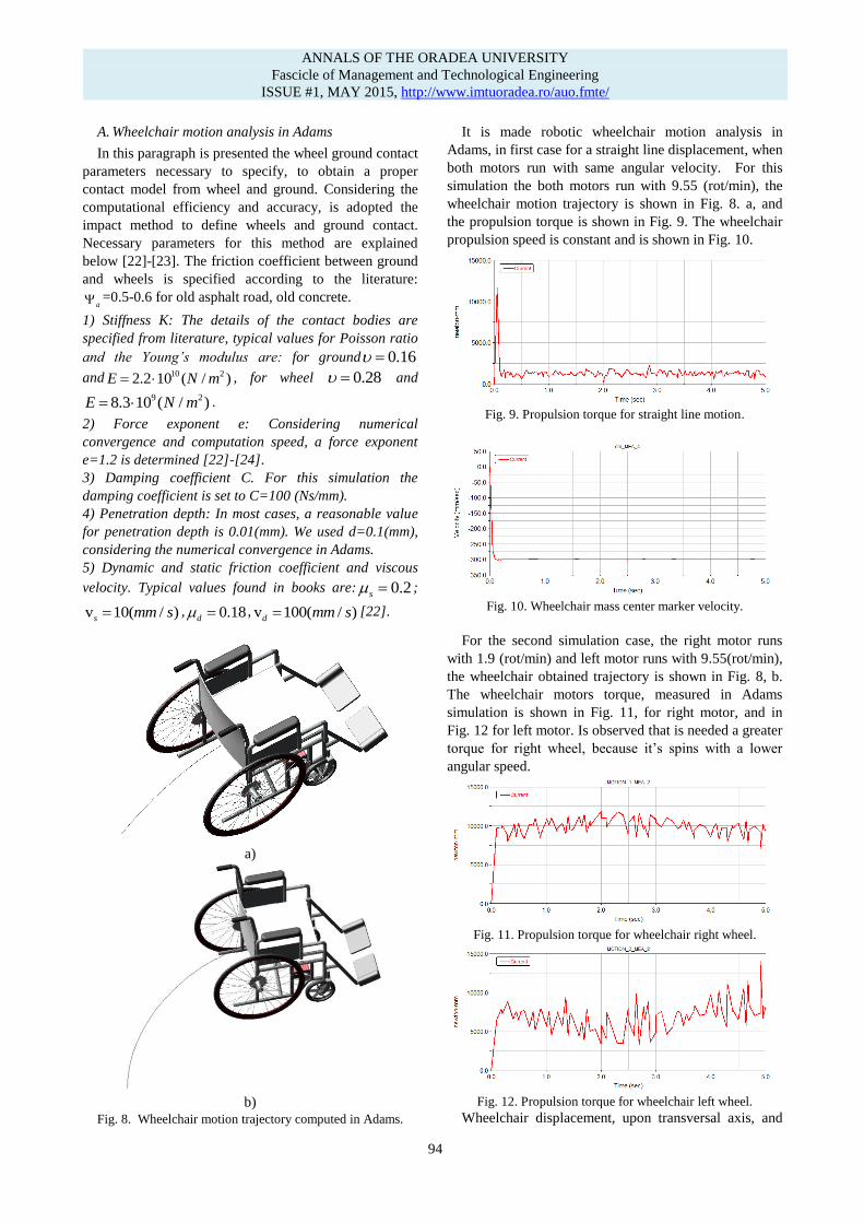
It is made robotic wheelchair motion analysis in
Adams, in first case for a straight line displacement, when
both motors run with same angular velocity. For this
simulation the both motors run with 9.55 (rot/min), the
wheelchair motion trajectory is shown in Fig. 8. a, and
the propulsion torque is shown in Fig. 9. The wheelchair
propulsion speed is constant and is shown in Fig. 10.
Fig. 9. Propulsion torque for straight line motion.
Fig. 10. Wheelchair mass center marker velocity.
For the second simulation case, the right motor runs
with 1.9 (rot/min) and left motor runs with 9.55(rot/min),
the wheelchair obtained trajectory is shown in Fig. 8, b.
The wheelchair motors torque, measured in Adams
simulation is shown in Fig. 11, for right motor, and in
Fig. 12 for left motor. Is observed that is needed a greater
torque for right wheel, because it’s spins with a lower
angular speed.
Fig. 11. Propulsion torque for wheelchair right wheel.
Fig. 12. Propulsion torque for wheelchair left wheel.
Wheelchair displacement, upon transversal axis, and
1
ANNALS OF THE ORADEA UNIVERSITY
Fascicle of Management and Technological Engineering
ISSUE #1, MAY 2015, http://www.imtuoradea.ro/auo.fmte/
94

longitudinal axis are shown in Fig. 13 and 14. For that
simulation case the wheelchair velocity magnitude is
shown in Fig. 15.
Fig.13. Wheelchair displacement, upon transversal axis.
Fig.14. Wheelchair displacement, upon longitudinal axis.
Fig.15. Wheelchair velocity magnitude.
B. Experimental evaluation of wheelchair motion
For wheelchair experimental motion evaluation it is
used motion analysis equipment – Contemplas, based on
ultra speed cameras [25]. Reflective markers have been
attached to the wheelchair frame and wheel. The marker
motion is captured and processed with TempoloMotion
software in order to establish wheelchair wheels rotation
and displacement variation in time. Positioning of
reflective marker is shown in Fig. 16 and motion tracking
results are indicated in Fig. 17.
The notations used are following:
1) back attached reflective marker.
2) front attached reflective marker.
3) wheel center attached marker.
4) wheel circumference attached marker.
With Contemplas motion analysis equipment, the
wheelchair is analyzed during a straight line
displacement. Obtained results for markers trajectories
and kinematic parameters are presented in the Fig. 18.
The graphic of the angular variation of wheel is presented
in Fig. 19.
Fig.16. Positioning of reflective markers on the wheelchair.
Processing the motion capture, it is obtained markers
trajectories, presented in Fig. 17.
Fig. 17. Markers obtained trajectories.
Is observed that the wheel circumference marker
describes a cycloid curve, and markers attached to the
frame are describing a straight line. Motion tracking
allow establishing the wheel angular position, and also
angular velocity.
a)
b)
Fig. 18. Motion tracking for wheel angular position establish.
1 2
3
4
1
ANNALS OF THE ORADEA UNIVERSITY
Fascicle of Management and Technological Engineering
ISSUE #1, MAY 2015, http://www.imtuoradea.ro/auo.fmte/
95

Fig. 19. Time variation of wheel angular position.
IV. CONCLUSION
This paper proposes to develop a kinematic analysis
model of a robotic wheelchair, which will be used for
further dynamic studies. In order to increase efficiency
propulsion motors must run at a high angular speed. For
that are implemented motors with reduction gears and
chain drive trains, in order to change the motor speed to a
lower speed and increase the available torque to wheels.
The virtual model of the wheelchair is designed in Solid
Works and upon this model is developed the
experimental model. Proposed solution uses two motors,
controlled by a joystick module, based on a PWM
controller. Kinematic analysis reveals motion trajectories
of wheelchair, kinematic parameters of the system: wheel
angular displacement and speed, running speed. Further
studies concerns the motion study for steering situation,
and establish of dynamic parameters of the wheelchair:
electric DC motors propulsion and steering torque.
ACKNOWLEDGMENT
This work was supported by the strategic grant
POSDRU/159/1.5/S/133255, Project ID 133255 (2014),
co-financed by the European Social Fund within the
Sectorial Operational Program Human Resources
Development 2007-2013.
REFERENCES
[1] Gonzalez-Rodriguez Antonio, Mechanical Synthesis for Easy and
Fast Operation in Climbing and Walking Robots, Climbing and
Walking Robots, Intech Viena, 2010.
[2] Gurpude R., Design, Synthesis & Simulation Of Four Bar
Mechanism For Guiding Wheel For Climbing, International
Journal of Engineering Research and Applications, 2012.
[3] Hassan Abdulkadir, Design and Fabrication of a Motorized
Prototype Tricycle for the Disable Persons, IOSR Journal of
Engineering, May 2012, Vol. 2(5), pp.1071-1074.
[4] Kumar Vijay, Assistive Devices for People with Motor
Disabilities, Wiley Encyclopedia of Electrical and Electronics
Engineering. Assistive Devices for People with Motor
Disabilities, 1997.
[5] R.F. Edlich, K.P. Nelson, M.L. Foley, R.M. Buschbacher, W.B.
Long and E.K. Ma, Technological advances in powered
wheelchairs, J. Long. Term. Eff. Med. Implants, vol. 14, pp.107-
130, 2004, visited April 2015:
http://dl.begellhouse.com/journals
/1bef42082d7a0fdf,06d27aa539906a9e,7b5a4f3a4794918e.html.
[6] ***,http://www.wheelchairnet.org/WCN_WCU/Research/Stakeh
olderDocs/PDFs/motors.pdf, visited April 2015.
[7] ***,http://t2rerc.buffalo.edu/pubs/forums/mobility/forum/white_p
apers/motors.htm, visited May 2015.
[8] Modak G. S., Review Article: Evolution of a Stair-Climbing
Power Wheelchair, IOSR Journal of Mechanical and Civil
Engineering (IOSR-JMCE), pp. 36-41, 2009.
[9] Shanu Sharma, User Centric Designed Mechanism For stairs-
climbing Wheelchair, 15th National Conference on Machines and
Mechanisms NaCoMM, 2011.
[10] Rajasekar R., Design and fabrication of staircase climbing
wheelchair, Int. J. Mech. Eng. & Rob. Res., 2013.
[11] Pires G., Autonomous Wheelchair for Disabled People, Proc.
IEEE Int. Symposium on Industrial Electronics (ISIE97),
Guimarães, 797-801, 1997.
[12] Salmin H., Design and Implementation of an Electric Wheelchair
to economize it with respect to Bangladesh, International Journal
of Multidisciplinary Sciences and Eng. 2014.
[13] Reswick JB., Automatic transmission for electric wheelchairs, J.
Rehabil. Res. Dev., 1985.
[14] Sheng L.J., Wireless brain computer interface for electric
wheelchairs with EEG and eye-blinking signals, International
Journal of Innovative Computing, Information and Control,
2012.
[15] Wellman, P., Design of a Wheelchair with Legs for People with
Motor Disabilities, IEEE Transactions on Rehabilitative Eng.
Vol. 3, pp.343-353, 1995.
[16] Wolm P., Dynamic stability control of front wheel drive
wheelchairs using solid state accelerometers and gyroscopes, PhD
Thesis, University of Canterbury, 2009.
[17] ***,http://www.wheelchairnet.org/WCN_WCU/SlideLectures/D
AH/AnatPoweredWCs-0699.pdf, visited April 2015.
[18] ***,https://www.pololu.com/product/1390/specs, visited April
2015.
[19] ***,http://www.instructables.com/id/Arduino-Modules-L298N-
Dual-H-Bridge-Motor-Controll/, visited April 2015.
[20] ***,http://www.mantech.co.za/datasheets/products/A000047.pdf,
visited April 2015.
[21] ***,http://www.digikey.com/product-highlights/us/en/arduino
/1037, visited April 2015.
[22] Kong D., Nonlinear Contact Analysis of Gear Teeth for
Malfunction Diagnostics, Conference and Exposition on
Structural Dynamics, 2008.
[23] ***,http://paper.uscip.us/jvamc/jvamc.2014.1002.pdf, visited
April 2015.
[24] MSC Inc., MSC Adams 2013 reference manual.
[25] Contemplas Software user manual.
An
gu
lar
po
siti
on
(d
eg)
0
50
100
150
200
250
300
350
400
0 2 4 6 8 10 12 14
Time (sec)
1
ANNALS OF THE ORADEA UNIVERSITY
Fascicle of Management and Technological Engineering
ISSUE #1, MAY 2015, http://www.imtuoradea.ro/auo.fmte/
96