motion technology catalog - moog inc. · 2020-05-14 · moog components group • moog is an...
TRANSCRIPT

1
Slip Rings, Fiber Optic Rotary Joints, Multiplexers and Fluid Rotary Unions
Motion Technology Catalog

Moog Components Group • www.moog.com/components
Moog is an innovative motion technology company with unique design and manufacturing capabilities for electromechanical and fiber optic products. Founded over 50 years ago, the company’s original vision was to become a research and development business offering new technologies for the emerging inertial navigation marketplace for aircrafts. Quickly, it evolved into a manufacturing operation where the designs were crafted into products that were in high demand.
Moog has a legacy for providing high-quality products used in critical defense and space applications. Over the years, this foundation has expanded to a broad spectrum of industrial markets, including medical, automation, marine and communications. The company is ISO9001 and AS9100 certified and utilizes world-class manufacturing concepts, including Six-Sigma and Lean Manufacturing, to allow the company to produce the highest quality products at competitive prices.
Today, Moog’s core business is motion. Product lines include slip rings, fiber optic rotary joints, motors, position sensors, actuators, fluid rotary unions, fiber optic components and air moving systems. There are seven manufacturing operations with locations in Virginia (Blacksburg and Galax), North Carolina (Murphy), Pennsylvania (Springfield), Canada (Halifax), England (Reading) and Florida, (Naples) with over 1,800 employees worldwide. Recent additions to the product portfolio are Moog Aspen Motion Technologies, Moog Protokraft and Moog Tritech.
Moog offers standard and customer-specific solutions for industrial, medical, marine, aerospace and defense applications. More information about Moog is available at www.moog.com.
2 Moog • www.moog.com
Your work demands the right moves.

3Moog • www.moog.com 3
Motion Technology Catalog Index
Moog • www.moog.com 3
Product Applications .......................................................................................... 4Selecting A Slip Ring ........................................................................................5-8 How To Specify A Slip Ring ............................................................................. 6 SlipRingApplicationSpecificationSheet ....................................................... 7 Components Of A Slip Ring ............................................................................ 8Product Overview ...........................................................................................9-13 CommercialSlipRingSpecificationMatrix ..................................................... 9 Aerospace/MilitarySlipRingProgramMatrix ............................................. 13Commercial Slip Ring Products ................................................................14-134 SlipRingsWithThrough-Bores ..................................................................... 15 Split Slip Rings .............................................................................................. 41 SlipRingCapsules(Compact) ...................................................................... 43 EthernetandHighDefinitionVideoSlipRingCapsules ............................... 70 HighSpeedSlipRingCapsules .................................................................... 90 LargeDiameterSlipRings .......................................................................... 100 Separates .................................................................................................... 104 Platter Separates ........................................................................................ 108 FiberOpticRotaryJoints(FORJ) ................................................................ 109 FiberOpticHybridUnits ............................................................................. 135Aerospace / Military Slip Ring Products ............................................... 137-160 Electro-OpticSystems ............................................................................... 138 VehicularSlipRings ................................................................................... 140 Helicopter Slip Rings ................................................................................... 146 Propeller Slip Rings .................................................................................... 148 MiniatureSlipRingCapsules ...................................................................... 150Marine / Energy Slip Ring Products ........................................................161-175 Slip Rings .................................................................................................... 162 FPSO Swivels ............................................................................................. 171 MultiplexersandMediaConverters ............................................................ 174Fluid Rotary Unions (FRU) .......................................................................176-184Integrated Mechanisms............................................................................185-187Technical Information ..............................................................................188-192 DigitalTechnology ....................................................................................... 189 FiberBrushTechnology ............................................................................. 191Product Summary............................................................................................ 195
MoogpartscomplywithEUDirective2002/95/EC(RestrictionofHazardousSubstances).Aproductlistingwillbeupdatedonanongoingbasis. Ifyouareinterestedinaproductlist,pleasevisitourwebsiteat:www.moog.com.
Note:This catalog contains basic marketing information and general part descriptions of Moog product lines. With respect to the U.S. export regulations, the products described herein are controlled by the U.S. Commerce Department or the U.S. State Department. Contact Moog for additional detail on the export controls that are applicable to your part.
Com
mercial
Slip R
ingsS
electing A Slip R
ing / ProductO
verviewM
arine / Energy
Slip R
ingsA
erospace / Military
Slip R
ingsIntegrated Mechanism
sFluidR
otaryUnions
TechnicalInformation
www.moog.com Email:[email protected]

4 Moog • www.moog.com
Product Applications
We have your motion application solutions.
Typical Applications
Aerospace / Defense• Armoredvehicleturrets,IRandEOsystems• Missileseekergimbalsandinertialsystems• Helicopterde-icesystems,EO/IRtrackers andtargetsystems
• Fixed-wingaircraft-EO/IRtrackers,firecontrol systems,surveillancesystemsandtargetingsystems
• Missilecountermeasures• Space-solararraymechanisms• Shipboard/submersible-navigationsystems andfirecontrolradar• Surveillancesystems
Commercial•Medicalequipmentanddevices• Robotics•Indextables•Semiconductorhandling• Pan tilt cameras•Packagingandprocessingequipment• Cable reels•Windenergy• CT scanners
Marine• RemoteOperatedVehicles(ROV)• Seismicsurveying• Oceanographicwinches• Subseacommunicationsandcontrol• FloatingProduction,StorageandOffshoreloading(FPSO)• Diving• Marineinstrumentation• Downhole/wirelogginganddrilling
4 Moog • www.moog.com

5Moog • www.moog.com 5
Product Applications
We have your motion application solutions.
Selecting A Slip Ring
Moog • www.moog.com 5

6 Moog • www.moog.com
How To Specify A Slip RingDefining the Mechanical EnvelopeTheenvelopeis,ofcourse,largelydictatedbythespaceavailableinthesystem.Theslipringengineershouldbegiventhemaximumspaceavailableinthesystemsoallexistingcandidatedesignscanbeconsidered. It isimperativethatthespacerequiredfortheslipringbespecifiedintheearlystagesof thesystemdesignandthatitbeconsistentwiththestructuralandelectricaldemands.
Defining System Interface RequirementsTheslipringengineerwillneedtoknowthesesysteminterfaceconsiderations:1.Can the slip ringmount directly on thecenterlineorisathrough-borerequiredintheslipring?Athrough-borecanbeusedtomounttheslipringonashaftorusedforroutinghydrauliclines,pneumaticlines,fiberopticrotaryjoint,waveguide.etc.2.Howwilltheslipringattachtothesystem?Aslipringmustbemountedwithaflexiblecoupling on one side of the unit. Hardmountingonboth the rotor and statorwillcause the slip ring to fail prematurely bytranslating system load into the slip ringbearingstructure.3.Howshouldtheelectricalconnectionstotheslipringbemade?Isitdesirabletohaveconnectorsintegralwiththeslipringonboththerotorandstator,orwouldflyingleadsononeortheotherendsbedesirable?Andifflyingleadsarepreferred,shouldtheyexittherotor/statorinaradialoraxialdirection,andwhatlengthshouldtheleadsbe?
Defining Electrical RequirementsThe specified current enables the slipring engineer to propose a unit with theappropriatecross-sectionalareaoftherings,brushesandleadwires.Thespecifiedvoltagedictatesthespacingbetweenadjacentringsandbrushes. It is helpful in achieving themost cost effective and smallest practicalenvelope not to rate all circuits at themaximumlevel.Forexample,ifyouneed20circuitstotal,threeofwhichmustcarrytenamps,designatethreeforhighcurrent.Don’tinsiston100%functionalinterchangeabilityby specifying that all 20 circuits carry tenamps.And, if tenamps isasurgecurrentwithacontinuouscurrentofonlytwoamps,tellusthat,too.Thereisnoreasonforyouto
payfortenampscontinuouscapacitywhenyouonlyneedtwoamps. Beawarethatvoltagesurgesandspikesarethemajorcauseofsystemslipringfailures.Moogusesaconservativeapproachtocircuitdesign,however,itisnotuncommoninsomepowersupplysystemstoseevoltagespikesten ormore times the normal operatingvoltage.We strongly recommend surgeprotectiononallpowersupplies.
Most smaller slip rings will satisfactorily conductsignalsto50megabits/sec.Specialslip rings canbeused to passbroadbandsignalsfromDCto1gigahertzanddataratesof500megabitsorevenhigher.Cross-talk,insertionlossandbiterrorrateinformationcanbeprojected,iftestedforactualvalues,whendata rates, formatsand impedancesare defined. The appropriate shieldingtechniqueswillbeincorporatedtomeetthesystemrequirements.
Defining Mechanical Requirements 1.Operating speed (rpm) is an importantdesignparameter.Almostanyslipringcanoperatesuccessfullyatspeedsto100rpmalthoughmany applications only requireoperation at a few rpm. Slip rings are routinelyusedtoinstrumenttestjetturbineengines operating at speeds in excessof 20,000 rpm. The operating speed, inconjunctionwith thediameter,dictates thesurfacespeedoftheringrelativetothebrushandhencetheinternaldesignapproachandmaterial selection.2.Whatrotationallifeisnecessaryforyourapplication?Willtheunitoscillateorrotateatacontinuousspeed?
Defining the EnvironmentTheenvironmentinwhichtheslipringmustsurviveisakeyfactor.Operatingtemperaturerange is important inspecifyingtheproperlubricant.And if the slip ringwill operateexposed to the elements or to a hostileenvironment,integralsealsmustbeincludedinthedesign.Anyunusualshockorvibrationshouldalsobespecified.
Your Slip Ring RequirementsForassistanceonyourslipringrequirements,please complete theSlip Ring Application Specification Sheetlocatedonpage7,youcaneitherfaxorcallandspeakwithoneofourengineersaboutyouroptimumslipringsolution.
Many of the slip ring designs and manufacturing processes described are proprietary and are covered under one or more U.S., European or Japanese patents. The information provided is intended to assist the system engineer in initial discussions and is not intended as a specification.
Many of themore than 10,000 slip ringdesignsareavailableforuseintheirexistingconfiguration or theymay bemodified tomeet your specific requirements. Newdesignscanalsobecreatedtomeetthemostdemandingspecifications.
Our engineers are experienced in awiderange of slip ring applications. A very active in-house quality program solicits the bestinputs from all of our many concurrentengineeringgroups,fromstarttofinish.
Thissectionisdesignedtoguideyouthroughtheprocessofspecifyingaslipring.We’veoutlinedbelowthemajorconsiderationsthataslipringengineerwillneedtoknowaboutyourapplication.
Basic Slip Ring Design Throughout these pages, you will seethree basic terms used for slip rings: 1. Slip RingCapsule -A fully integrateduni t wi th a housing and bear ings. 2.SlipRingSeparates-Separateslipringrotorandbrushblocksformountinginyoursystem. 3.TwistCapsule-Alimitedrotationdeviceusedtypicallyinscanningapplicationswherecontinuousrotationisnotrequired.
Therearetwobasicslipringconfigurationsto consider based on space allocation in yoursystem:
1. The more common drum approachwhere each r ing is adjacent to thenext along the centerline, somewhatl i k e t h e t h r e ads o n a b o l t a nd 2.Theplatterapproachwheretheringsareconcentricwithoneanotherlikethegrooveson a flat surface.The pancake approachis usedwhen length is at a premiumbutdiameterislessrestrictive.

7Moog • www.moog.com 7
Slip Ring Application Specification Sheet
6) Specifications:
NumberofRings:
Size: Length
Diameter
Bore
Wear(Life): Hours(orYrs)
atDutyCycle
OperatingTempRange(°C):
Min MaxNorm
Pressure:NormMin
Vibration:g’s@HzShockg’s
Sealing: None Dust&Splash
Water Spray Submersion
RotationalSpeed: Norm
OscillatoryMotion:YesNo
Torque:MaxStartinggm-cm
Weight(Max):
LeadLength:Rotor Stator
Connectors: Rotor Stator
LeadExits: RotorAxial Radial
StatorAxial Radial
Company Information
CompanyName
Division
Address
City State/CountryZip/PostCode
Phone FAX
Contact
Buyer
Engineer
Other
1)DescriptionofApplication: Commercial Industrial Military Other 2) TypeofSlipRing Capsule SeparateBrushBlock Other Separate Slip Ring Poly-Twist(for±°)
3) ThisApplicationis: New Retrofit/ReplacementTypeofApplication: CurrentSupplier: PartNumber:
4) EstimatedAnnualQuantity: PriceTarget: ProductionStartDate:
EstimatedLifeofProgram: Tooling$Available:
5) SizeConstraints-Mechanicalandadditionalrequirements(i.e.resolver,motor,hydraulics,pneumatics,opticalchannel,etc):
Pleaseprovideasmuchinformationaspossible,enterNAforthosequestionsthatarenotcriticalorimportanttoyou.Donotbeconcernedifyoudonothaveallofthespecificationsthatarerequested,wearehappytoworkwithaslittleorasmuchinformationasyoucanprovide.However,themorecompleteyourresponse,themorethoroughouranalysis.
*If unknown please specify protocol or data rate.
800-336-2112 • +1-540-552-3011 • email: [email protected] • www.moog.com
CircuitFunction
No. Ring
Current(amps) WorkingVolts
DataProtocol
DigitalRisetime*orFreq.(Hz)
CrosstalkIsolation(dB)
Normal Max

8 Moog • www.moog.com
Components Of A Slip Ring
FIBERBRUSH
BARRIER(Insulation Between Rings)
RING
DEROTATION TAB
STATOR ENDCAP
STATORLEADS
BRUSHBLOCK
STATOR ENDCAP
ROTOR
ROTORLEADSBEARINGS
Note:Outerhousingisremovedforclarity.

9Moog • www.moog.com 9
Commercial Slip Ring Specification Matrix
Slip Rings with Through-BoresPart
##
RingsContinuous Current (amps) Coaxial Standard Operating
Voltage (AC)Size Bore Rated
SpeedPage
#2 5 10 15 30 50 RG178 RG179 120 240 440 600 DIA” x LG” DIA” RPM
SRA-73683-6 6 6 X 1.38 x 1.07 .5 250 15
SRA-73683-12 12 12 X 1.38 x 1.37 .5 250 15
SRA-73683-18 18 18 X 1.38 x 1.67 .5 250 15
SRA-73683-24 24 24 X 1.38 x 1.97 .5 250 15
AC6438-6 6 6 X 2.1 x 1.75 .5 250 17
AC6438-12 12 12 X 2.1 x 2.3 .5 250 17
AC6438-18 18 18 X 2.1 x 2.9 .5 250 17
AC6438-24 24 24 X 2.1 x 3.4 .5 250 17
AC6349-6 6 6 X 3.07 x 2.9 1 250 19
AC6349-12 12 12 X 3.07 x 4.1 1 250 19
AC6349-18 18 18 X 3.07 x 5.3 1 250 19
AC6349-24 24 24 X 3.07 x 6.5 1 250 19
AC6875 IP 65 sealed version of AC6349 3.07 x 2.9 - 6.5 1.0 250 21
AC4598-6 6 6 X 3.9 x 2.13 1.5 250 22
AC4598-12 12 12 X 3.9 x 3.07 1.5 250 22
AC4598-18 18 18 X 3.9 x 4.01 1.5 250 22
AC4598-24 24 24 X 3.9 x 4.94 1.5 250 22
AC6200-12 12 12 X 3.9 x 2.13 1.5 250 24
AC6200-24 24 24 X 3.9 x 3.07 1.5 250 24
AC6200-36 36 36 X 3.9 x 4.01 1.5 250 24
AC6200-48 48 48 X 3.9 x 4.94 1.5 250 24
AC6200-6P/12S 18 12 6 X (2A) X (10A) 3.9 x 3.07 1.5 250 24
*AC6200-6P/24S 30 24 6 X (2A) X (10A) 3.9 x 4.01 1.5 250 24
AC6200-6P/36S 42 36 6 X (2A) X (10A) 3.9 x 4.94 1.5 250 24
AC6200-12P/12S 24 12 12 X (2A) X (10A) 3.9 x 4.01 1.5 250 24
AC6200-12P/24S 36 24 12 X (2A) X (10A) 3.9 x 4.94 1.5 250 24
AC6200-18P/12S 30 12 18 X (2A) X (10A) 3.9 x 4.94 1.5 250 24
AC6419 IP 65 sealed version of AC4598 and AC6200 series 3.9 x 2.3 - 5.1 1.5 250 26
AC6815 Up to 128 X 3.5 X 2A/60 3.5A/110 10A/220 4.32 x 3.01 - 5.94 1.5 250 27
AC6428-060 60 60 X 3.9 x 6.6 1.375 250 29
AC6428-072 72 72 X 3.9 x 7.5 1.375 250 29
AC6428-084 84 84 X 3.9 x 8.45 1.375 250 29
AC6428-096 96 96 X 3.9 x 9.34 1.375 250 29
AC6429-006 54 48 6 X (2A) X (10A) 3.9 x 7.5 1.375 250 29
AC6429-012 60 48 12 X (2A) X (10A) 3.9 x 7.5 1.375 250 29
AC6275 Up to 144 X X X X X X X (5A) X 6.63 x 6.6 - 20.5 2.75 1000 31
AC6793 IP 65 sealed version of AC6275 6.63 x 6.6 - 20.5 2.75 1000 33
AC6098 Up to 72 X X X X X X 8.0 x 4.6 - 14.4 4 250 34
Std W Series Up to 24 X X X X 5A/250 30A 5.0 x 1.89 - 5.89 1.5 60 36
Std W Series Up to 24 X X X X 5A/250 30A 6.5 x 1.89 - 5.89 3.0 60 36
Fiber W Series Up to 48 X X X X 5A/250 30A 5.0 x 2.43 - 10.38 1.5 250 38
Fiber W Series Up to 48 X X X X 5A/250 30A 6.5 x 2.32 - 10.38 3.0 250 38
Fiber W Series Up to 48 X X X X 5A/250 30A 7.5 x 2.18 - 10.38 4.0 250 38
Fiber W Series Up to 48 X X X X 5A/250 30A 9.5 x 2.19 - 10.38 6.0 250 38
Fiber W Series Up to 48 X X X X 5A/250 30A 12.5 x 2.43 - 10.38 9.0 250 38
Continued on next page
REVISED 01/19

10 Moog • www.moog.com
Commercial Slip Ring Specification Matrix
Split Slip RingsPart
##
RingsContinuous Current
(amps)Coaxial Standard Operating
Voltage (AC)Size Bore Rated
SpeedPage
#2 5 10 15 30 50 RG178 RG179 120 240 440 600 DIA” x LG” DIA” RPM
56814-950 8 8 X 4.134 x 1.969 2.953 250 41
56871-951 4 4 X 7.165 x 0.787 5.984 250 41
57165-950 5 5 X 2.102 x 1.220 1.652 250 41
57622-950 8 8 X 9.291 x 1.575 7.01 150 41
Slip Ring Capsule (Compact)Part
##
RingsContinuous Current (amps) Coaxial Standard Operating
Voltage (AC)Size Bore Rated
SpeedPage
#2 5 7 10 14 15 30 50 RG178 RG179 120 240 440 600 DIA” x LG” DIA” RPM
SRA-73540-6 6 6 X .44 x .64 250 43
SRA-73540 12 12 X .44 x .64 250 43
SRA-73625 18 18 X .44 x 1.16 250 45
AC6373-6 6 6 X .5 x .8 100 47
AC6373-12 12 12 X .5 x 1.07 100 47
SRA-73762-12 12 12 X .61 x 1.79 250 53
SRA-73762-18 18 18 X .61 x 1.79 250 53
SRA-73762-24 24 24 X .61 x 1.79 250 53
SRA-73526 6, 18 X X .87 x .57 - 1.11 250 49
SRA-73528 12 X X .87 x .76 250 49
SRA-73599 24 X X .87 x 1.24 250 49
AC6023-6 6 6 X .87 x 1.14 250 51
AC6023-12 12 12 X .87 x 1.41 250 51
AC6023-18 18 18 X .87 x 1.68 250 51
AC6023-24 24 24 X .87 x 1.95 250 51
AC6305-6 9 6 3 X .87 x 1.95 250 60
AC6305-9 12 9 3 X .87 x 1.95 250 60
AC6305-12 15 12 3 X .87 x 1.95 250 60
AC6310-3 6 3 3 X .87 x 1.95 250 60
AC6310-6 9 6 3 X .87 x 1.95 250 60
SRA-73574 36 36 X .87 x 2.4 250 55
SRA-73587 28 24 4 X .87 x 2.4 250 55
AC6355-36 36 36 X 1 x 2.6 250 57
AC6355-36V 32 28 4 X 1 x 2.6 250 57
AC6355-36X 24 20 4 X 1 x 2.6 250 57
AC6355-36C 26 20 4 2 X 1 x 2.6 250 57
AC6355-36K 26 20 4 2 X 1 x 2.6 250 57
AC6355-56 56 56 X 1 x 3.5 250 57
AC6355-56V 52 48 4 X 1 x 3.5 250 57
AC6355-56X 44 40 4 X 1 x 3.5 250 57
AC6355-56C 46 40 4 2 X 1 x 3.5 250 57
AC6355-56K 46 40 4 2 X 1 x 3.5 250 57
AC7356 IP 65 sealed version of AC6355 ** Product Replaced AC7038** Contact factory for details. 1 x 2.97 - 3.87 250 59
AC7036 Up to 80 X X X X X X X X 3.1 x 3.1 - 6.7 250 64
AC7212 X X X X X X X X 3.9 x 3.11 - 5.92 250 66
AC7094-130 30 30 X 2.17 x 6.00 250 62
AC7094-136 36 36 X 2.17 x 6.55 250 62
AC7094-142 42 42 X 2.17 x 7.11 250 62
AC7094-148 48 48 X 2.17 x 7.67 250 62
Continued on next page REVISED 03/17

11Moog • www.moog.com 11
Commercial Slip Ring Specification Matrix
Ethernet and High Definition Video Slip RingsPart
#Continuous Current
(amps)Coaxial Ethernet Size Bore Rated
SpeedPage
#2 5 10 RG178 RG179 HD-SDI 100BaseT 1000BaseT
(or 2 100BaseT)DIA” x LG” DIA” RPM
SRA-73806 9 1 .44 x 1.16 250 71
SRA-73799 6 1 .44 x 1.16 250 71
SRA-73805 12 1 .61 x 1.79 250 73
SRA-73798 12 1 .61 x 1.79 250 73
SRA-73810 12 1 .61 x 1.79 250 79
AC7203-6 1 .87 x 1.14 250 75
AC7203-12 6 1 .87 x 1.41 250 75
AC7203-12V 2 1 .87 x 1.41 250 75
AC7203-12G 1 .87 x 1.41 250 75
AC7203-18 12 1 .87 x 1.68 250 75
AC7203-18V 6 2 1 .87 x 1.68 250 75
AC7203-18X 2 2 1 .87 x 1.68 250 75
AC7203-18G 6 1 .87 x 1.68 250 75
AC7203-18GV 2 1 .87 x 1.68 250 75
AC7023-24 18 1 .87 x 1.95 250 75
AC7203-24V 12 2 1 .87 x 1.95 250 75
AC7203-24X 8 2 1 .87 x 1.95 250 75
AC7203-24G 12 1 .87 x 1.95 250 75
AC7203-24GV 6 2 1 .87 x 1.95 250 75
Slip Ring Capsule (Compact)Part
##
RingsContinuous Current (amps) Coaxial Standard Operating
Voltage (AC)Size Bore Rated
SpeedPage
#2 5 7 10 14 15 30 50 RG178 RG179 120 240 440 600 DIA” x LG” DIA” RPM
80050-957 / 1028300-2
2 2 X 1.248 x 2.54 400 68
80050-958 / 1028300-4
4 2 2 X 1.248 x 2.54 400 68
80050-956 2 2 X 1.248 x 2.54 400 68
80050-955 4 2 2 X 1.248 x 2.54 400 68
80059-950 8 8 X 1.58 x 3.07 600 68
High Speed Slip Ring CapsulesPart
##
RingsContinuous Current (amps) Coaxial Standard Operating
Voltage (AC)Size Bore Rated
SpeedPage
#1 2 2.5 5 10 15 30 50 RG178 RG179 120 240 440 600 DIA” x LG” DIA” RPM
EC4294 2 X X 1.2 x .68 10,000 96
EC3848-6 6 X X 1.2 x .98 10,000 96
EC4199 8 X X 1.2 x .92 10,000 96
EC3848-10 10 X X 1.2 x 1.2 10,000 96
AC3757 36 X 70V 1.625 x 2.53 6,000 92
80042-950 8 X 50V 1.52 x 2.29 20,000 90
80043-950 12 X 50V 1.52 x 2.79 20,000 90
80038-950 8 X 50V 3.56 x 5.28 12,000 98
80039-950 12 X 50V 3.56 x 5.88 12,000 98
80027-950 24 X 50V 3.56 x 8.64 12,000 98
AC6266 4 X X 4.25 x 1.97 1.5 2,500 94
AC6231 8 X X 4.25 x 2.75 1.5 2,500 94
Continued on next page

12 Moog • www.moog.com
Commercial Slip Ring Specification MatrixEthernet and High Definition Video Slip Rings
Part #
Continuous Current (amps)
Coaxial Ethernet Size Bore Rated Speed
Page #
2 5 10 RG178 RG179 HD-SDI 100BaseT 1000BaseT (or 2 100BaseT)
DIA” x LG” DIA” RPM
AC7203-24GX 2 2 1 .87 x 1.95 250 75
AC7203-24GG 2 .87 x 1.95 250 75
AC7188 8 1 .87 x 1.68 250 77
AC7188-18V 2 2 1 .87 x 1.68 250 77
AC7188-24 14 1 .87 x 1.95 250 77
AC7188-24V 8 2 1 .87 x 1.95 250 77
SRA-73811 4 2 .87 x 1.79 250 81
AC7217-C 13 2 1 1.0 x 2.6 250 85
AC7217-H 13 1 1 1.0 x 2.6 250 85
AC7217-N 23 1 1.0 x 2.6 250 85
AC7217-G 10 2 1.0 x 2.6 250 85
AC7217-K 13 2 1 1.0 x 2.6 250 85
AC7217-V 15 4 1 1.0 x 2.6 250 85
AC7217-X 15 2 1 1.0 x 2.6 250 85
AC7195-CC 23 4 1 1.0 x 3.5 250 83
AC7195-CG 20 2 2 1.0 x 3.5 250 83
AC7195-CH 23 2 1 1 1.0 x 3.5 250 83
AC7195-CK 23 2 2 1 1.0 x 3.5 250 83
AC7195-CN 33 2 1 1.0 x 3.5 250 83
AC7195-CV 25 4 2 1 1.0 x 3.5 250 83
AC7195-CX 25 2 2 1 1.0 x 3.5 250 83
AC7195-GG 17 3 1.0 x 3.5 250 83
AC7195-GH 20 1 2 1.0 x 3.5 250 83
AC7195-GK 20 2 2 1.0 x 3.5 250 83
AC7195-GN 30 2 1.0 x 3.5 250 83
AC7195-GV 22 4 2 1.0 x 3.5 250 83
AC7195-GX 22 2 2 1.0 x 3.5 250 83
AC7195-HH 23 2 1 1.0 x 3.5 250 83
AC7195-HK 23 2 1 1 1.0 x 3.5 250 83
AC7195-HN 33 1 1 1.0 x 3.5 250 83
AC7195-HV 25 4 1 1 1.0 x 3.5 250 83
AC7195-HX 25 2 1 1 1.0 x 3.5 250 83
AC7195-KK 23 4 1 1.0 x 3.5 250 83
AC7195-KN 33 2 1 1.0 x 3.5 250 83
AC7195-KX 25 2 2 1 1.0 x 3.5 250 83
AC7195-NN 43 1 1.0 x 3.5 250 83
AC7195-NV 35 4 1 1.0 x 3.5 250 83
AC7195-NX 35 2 1 1.0 x 3.5 250 83
AC7195-VV 27 8 1 1.0 x 3.5 250 83
AC7195-VX 27 4 2 1 1.0 x 3.5 250 83
AC7195-XX 27 4 1 1.0 x 3.5 250 83
SRA-73808 12 1 1.375 x 1.97 .5 250 87
SRA-73801 12 1 1.375 x 1.97 .5 250 87
AC6438 X X X X X 2.1 x 1.6 - 3.2 .5 250 17
AC4598 X X X X X 3.9 x 2.13 - 4.94 1.5 250 22
AC6275 X X X X X X 6.63 x 6.6 - 20.5 2.75 1000 33
AC6098 X X X X X 8.0 x 4.6 - 14.4 4.00 250 34

13Moog • www.moog.com 13
Aerospace / Military Slip Ring Program MatrixSIGCKTS=SignalCircuits(Rings)PWRCKTS=PowerCircuits(Rings)
Program DescriptionBradleyFightingVehicle Commander’sIndependentViewerAZSlipRing
A3TurretSlipRing,ELPoly-Twist
A2TurretSlipRing
AdvancedTargetingPod PitchAxisSlipRing
RollAxisSlipRing
AH-64A/DApache Longbow Attack Helicopter
Slip Ring RF Rotary Joint Assembly
AH64Apache TailRotorDe-ice
AvengerAirDefenseSystem TurretSlipRingCapsule
BlackhawkandSeahawk Main Rotor
Tail Rotor
F-14/15/16LANTIRN MainDe-rollSlipRing
SentinelRadar PedestalSlipRingCapsule
V-22Osprey Main Prop Rotor Slip RingDe-iceandFlightControls
StrykerIAVMobileGunSystem TurretSlipRingAssembly
F35JointStrikeFighter EOTS Roll Slip Ring
S92 Helicopter MainRotorDe-iceSlipRing
TailRotorDe-iceSlipRing
AWACS MainPowerandSignalTransferSlip Ring / RF Rotary Joint
MainPowerandSignalTransferSlip Ring / RF Rotary Joint

14 Moog • www.moog.com
Commercial Slip Ring Products
Moog • www.moog.com14

15Moog • www.moog.com 15
Slip Rings With Through-Bores
SRA-736831/2 inch through-bore miniature slip ring capsule
DescriptionA slip ring capsule can be used in any electromechanical systemthat requires unrestrained, intermittent or continuous rotationwhiletransferring power and / or data.A slip ring is also called a rotaryelectricaljoint,collector,commutatororswivel.Aslipringcanimprovesystemperformancebysimplifyingoperationsandeliminatingdamageprone wires.
TheSRA-73683providesaneconomical, readily available solutionwhen a compact through-bore configuration is required.This unitprovidesa1/2inchthrough-boreforshaftmounting,acompact1.375inchoutsidediameterandaveryshortoveralllengthforminimalspaceapplications.TheSRA-73683provides2ampcircuitsin6,12,18and24ringconfigurations.
Features• 1/2inchthrough-bore• Compact1.375inchoutsidediameter• Speedsupto250rpmcontinuous• Continuousrotationofpowerand/ordatasignals• Ethernetmodel,SRA-73801,available
Benefits• Transferspower,aswellasanaloganddigitalsignals• Compatiblewithdatabusprotocols• Compact packaging
Typical Applications
• Precisionrotaryequipment• Semiconductorhandlingsystems• Robotics• Camera systems
REVISED 06/16

16 Moog • www.moog.com
Slip Rings With Through-Bores
SRA-73683 SpecificationsOperatingSpeed 250rpm*NumberofCircuits 6,12,18,24LeadLength 12,24,36and48inchesLeadSize/Type #26AWG,Teflon®insulated,strandedVoltage 210VACOperating Temp. -40°Cto+80°CContact Material GoldCurrentRating 2A,perring,max.ElectricalNoise 40milliohmmax.
*Please note that the operational life of the unit is dependent upon rotational speed, environment and temperature.
Wire Color CodeRing # Color Ring # Color
1 BLK 13 WHT-RED
2 BRN 14 WHT-ORN
3 RED 15 WHT-YEL
4 ORN 16 WHT-GRN
5 YEL 17 WHT-BLU
6 GRN 18 WHT-VIO
7 BLU 19 WHT-GRY
8 VIO 20 WHT-BLK-BRN
9 GRY 21 WHT-BLK-RED
10 WHT 22 WHT-BLK-ORN
11 WHT-BLK 23 WHT-BLK-YEL
12 WHT-BRN 24 WHT-BLK-GRN
SRA-73683 Dimensions
Part Number Length “L” Ring Qty.SRA-73683-6 .82inch(20,83mm) 6
SRA-73683-12 1.12inch(28,45mm) 12
SRA-73683-18 1.42inch(36,07mm) 18
SRA-73683-24 1.72inch(43,69mm) 24
Dimensions in inches
REVISED 05/17

17Moog • www.moog.com 17
Slip Rings With Through-Bores
AC64381/2 inch through-bore miniature slip ring capsule
DescriptionA slip ring capsule can be used in any electromechanical systemthat requires unrestrained, intermittent or continuous rotationwhiletransferring power and / or data.A slip ring is also called a rotaryelectricaljoint,collector,commutatororswivel.Aslipringcanimprovesystemperformancebysimplifyingoperationsandeliminatingdamageprone wires.
TheAC6438providesaneconomical,readilyavailablesolutionwhenacompactthrough-boreconfigurationisrequired.Thisunitprovidesa1/2inchthrough-boreforroutingofhydraulicorpneumaticlines,andacompact2.1 inchoutsidediameterandaveryshortoverall lengthforminimalspaceapplications.TheAC6438provides5ampcircuitsin6,12,18and24ringconfigurations.Similar indesigntoourverypopularAC4598andAC6200series,thisdesignfeatureslonglife,fiberbrushcontacttechnologyforultimateperformanceinmanychallengingapplications.
Features• 1/2inchthrough-bore• Compact2.1inchoutsidediameter• Speedsupto250rpm• Multiplecircuitconfigurations• Continuousrotationofpowerand/ordatasignals• High-impactthermoplasticconstruction• Goldplatedrings• AvailablewithEthernet
Benefits• Transferspower,aswellasanaloganddigitalsignals• Compatiblewithdatabusprotocols• Fiberbrushtechnologyprovideslonglifeandmaintenance free operation• Compact packaging
Typical Applications
•Precisionrotaryequipment• Semiconductorhandlingsystems• Industrialmachinery• Robotics

18 Moog • www.moog.com
Slip Rings With Through-Bores
*Please note that the operational life of the unit is dependent upon rotational speed, environment and temperature.
Dimensions in inches (millimeters)
AC6438 Specifications OptionsOperatingSpeed 250rpm* •24,36and48inchleads
•Alternateleadexits• AvailablewithEthernet,contactfactory
NumberofCircuits 6,12,18or24LeadLength 12inchstandardLeadSize/Type 22AWGVoltage 240VACOperating Temp. -40°Cto+80°CCurrentRating 5amps/circuitElectricalNoise 100milliohmsmax.
Wire Color CodeRing # Color Ring # Color Ring # Color
1 BLK 9 GRY 17 WHT/BLU2 BRN 10 WHT 18 WHT/VIO3 RED 11 WHT/BLK 19 WHT/GRY4 ORN 12 WHT/BRN 20 WHT/BLK/BRN5 YEL 13 WHT/RED 21 WHT/BLK/RED6 GRN 14 WHT/ORN 22 WHT/BLK/ORN7 BLU 15 WHT/YEL 23 WHT/BLK/YEL8 VIO 16 WHT/GRN 24 WHT/BLK/GRN
Part Number AC6438-106 AC6438-112 AC6438-118 AC6438-124Dimension“A” 1.55inch(39,37mm) 2.11inch(53,60mm) 2.67inch(67,81mm) 3.23inch(82,04mm)Dimension“B” 1.33inch(33,78mm) 1.89inch(48,01mm) 2.44inch(61,98mm) 3.00inch(76,20mm)
AC6438 Dimensions
Part Number “A”AC6438 12in(304.8mm)AC6438-A 24in(609.6mm)AC6438-B 36in(914.4mm)AC6438-C 48in(1219.2mm)

19Moog • www.moog.com 19
Slip Rings With Through-Bores
AC63491 inch through-bore various circuit configurations
DescriptionA slip ring capsule can be used in any electromechanical systemthat requiresunrestrained, intermittent, or continuous rotationwhiletransferringpowerand/ordata.
TheAC6349providesaneconomical,readilyavailablesolutionwhenacompactthrough-boreconfigurationisrequired.Thisunitprovidesa1inchthrough-boreforroutinghydraulicorpneumaticlinesandacompact3.1inchoutsidediameterforminimalspaceapplications.The15ampcircuitsareavailablein6,12,18and24ringconfigurationsin4housinglengths.SimilarindesigntoourverypopularAC4598,thisdesign features long life,fiberbrushcontact technology forultimateperformanceinmanychallengingapplications.Fiberbrushesdonotrequirelubricationandproducevirtuallynoweardebris,formaintenancefree operation.
Features• 1inchbore• 6,12,18and24circuitmodels• Preciousmetalcontacts• 15 amp rings• Precision ball bearings for long life• Speedsupto250rpm• Compactsize• Sealedunitsavailable• Flyingleads• FullycompatiblewithbothanalogandTTLcontrollevelsignals• Ruggedblackanodizedaluminumconstruction• AvailablewithEthernet
Benefits• Uniquesignalhandlingperformancewithminimal electricalcircuitnoise• Tightpackagingtofitinthemostdemandingspaceconstraints• Lowtorquetominimizesystemtorquebudget• Rapiddelivery
Typical Applications
• Packaging/wrappingmachinery• Semiconductorhandlingsystems• Industrialmachinery• Robotics
20 Moog • www.moog.com
Slip Rings With Through-Bores
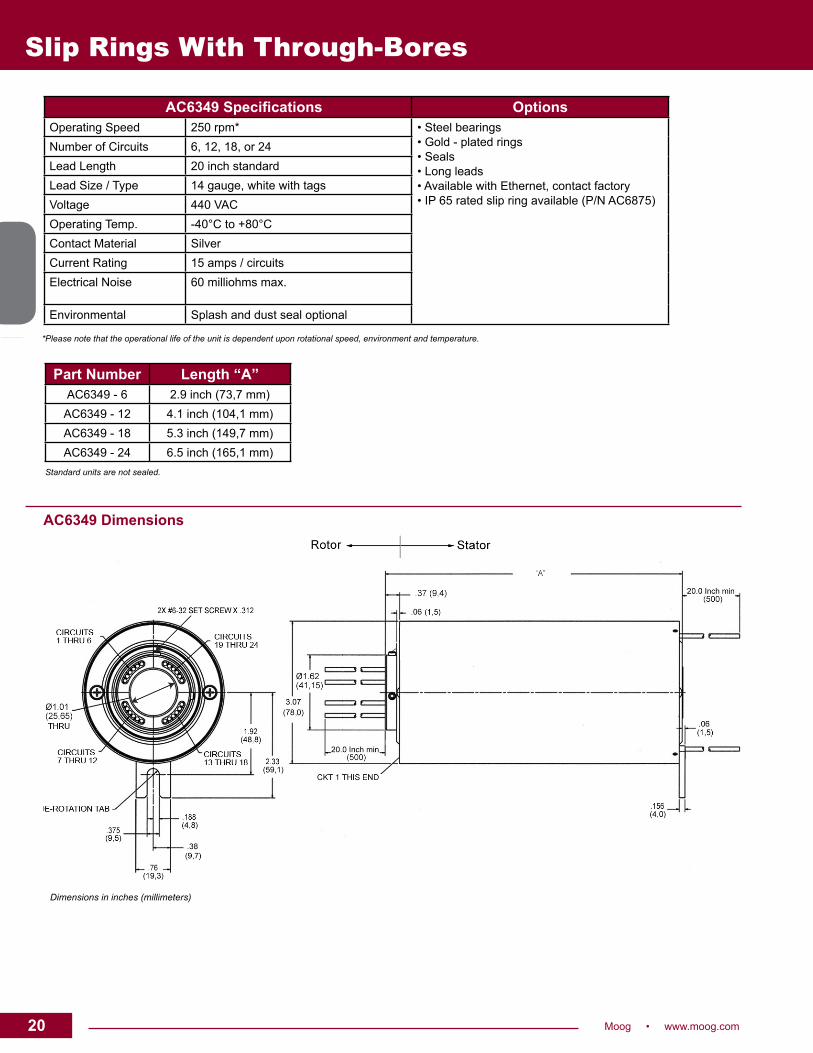
Part Number Length “A”AC6349-6 2.9inch(73,7mm)AC6349-12 4.1inch(104,1mm)AC6349-18 5.3inch(149,7mm)AC6349-24 6.5inch(165,1mm)
Standard units are not sealed.
AC6349 Specifications OptionsOperatingSpeed 250rpm* • Steel bearings
•Gold-platedrings• Seals•Longleads•AvailablewithEthernet,contactfactory•IP65ratedslipringavailable(P/NAC6875)
NumberofCircuits 6,12,18,or24LeadLength 20inchstandardLeadSize/Type 14gauge,whitewithtagsVoltage 440VACOperating Temp. -40°Cto+80°CContact Material SilverCurrentRating 15amps/circuitsElectricalNoise 60milliohmsmax.
Environmental Splashanddustsealoptional
AC6349 Dimensions
Dimensions in inches (millimeters)
*Please note that the operational life of the unit is dependent upon rotational speed, environment and temperature.
21Moog • www.moog.com 21
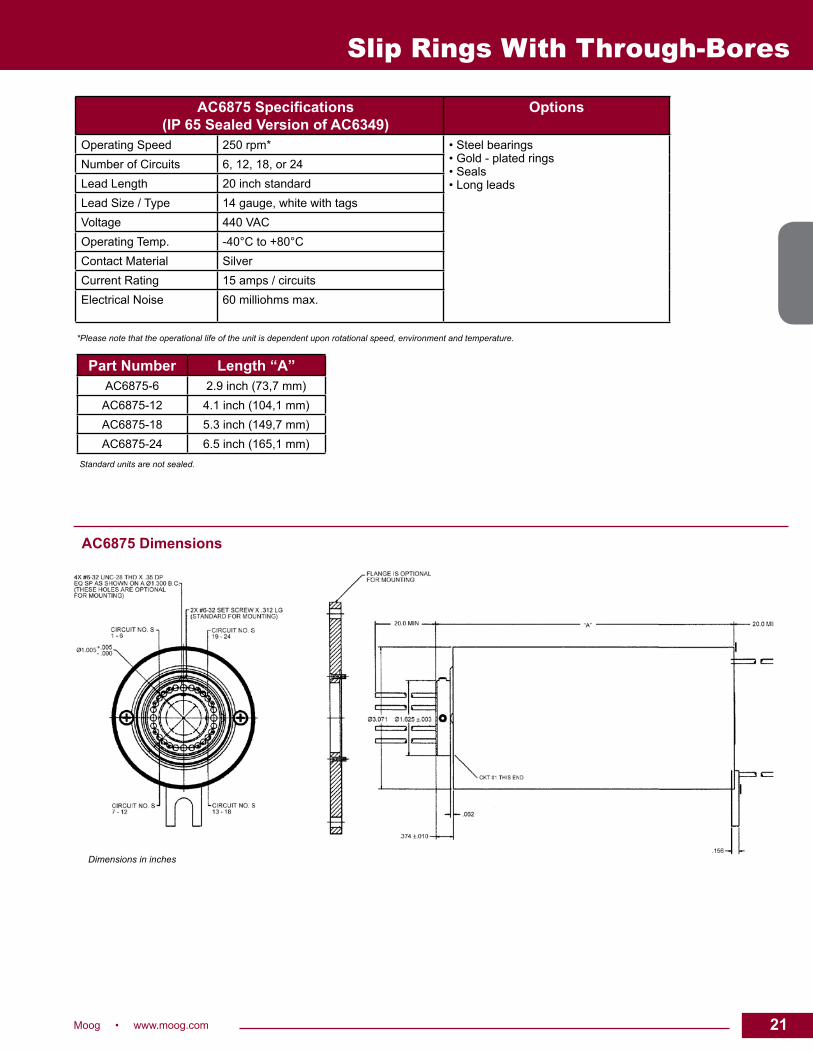
Part Number Length “A”AC6875-6 2.9inch(73,7mm)AC6875-12 4.1inch(104,1mm)AC6875-18 5.3inch(149,7mm)AC6875-24 6.5inch(165,1mm)
Standard units are not sealed.
AC6875 Specifications (IP 65 Sealed Version of AC6349)
Options
OperatingSpeed 250rpm* • Steel bearings•Gold-platedrings• Seals•Longleads
NumberofCircuits 6,12,18,or24LeadLength 20inchstandardLeadSize/Type 14gauge,whitewithtagsVoltage 440VACOperating Temp. -40°Cto+80°CContact Material SilverCurrentRating 15amps/circuitsElectricalNoise 60milliohmsmax.
AC6875 Dimensions
Dimensions in inches
*Please note that the operational life of the unit is dependent upon rotational speed, environment and temperature.
Slip Rings With Through-Bores

22 Moog • www.moog.com
Slip Rings With Through-Bores
Typical Applications
•Industrialmachinery-machining centers,rotaryindextables,heavy equipmentturretsorcablereels, testequipment,packaging machines,palletizingmachines, magneticclutches,processcontrol equipment,rotarysensors, emergencylighting,robotics•Exhibit/displayequipment•Medicalequipment
AC4598 10 amp per circuit 1-1/2 inch through-bore
DescriptionAslipringcanbeusedinanyelectromechanicalsystemthatrequiresunrestrained,continuousrotationwhiletransferringpowerand/ordatafromastationarytoarotatingstructure.Aslipringisalsocalledarotaryelectricalinterface,collector,swivel,orarotaryjoint.Aslipringcanimprovesystemperformancebysimplifyingoperationsandeliminatingdamage-pronewiresdanglingfrommovablejoints.
The 1-1/2 inch through-bore provides routing space for hydraulics,pneumaticsorforaconcentricshaftmount.
TheAC4598usesouruniquefiberbrushtechnologywhichoffersseveraladvantagesoverconventionalslipringcontacts,includingmultiplepointsofcontactperbrushbundle,lownoise,electricalandlowcontactwearrates.Inaddition,fiberbrushesdonotrequirelubricationandproducevirtuallynoweardebris.
Features•1-1/2inchthrough-bore•Speedsupto250rpm•6,12,18or24tenampcircuits•16gauge,12inchleadwire-longerleadlengthsareavailable•Higherrotationalspeedswithalternatebearings(optional)•Variousaxialandradialleadexitsareavailable•Splashsealsfordustandmoistureresistance•Standardcollarmounting-flangemountingoptional•Alsoavailablewith12,24,36and48,2ampringsorpowerandsignalcombinations.PleaserefertoAC6200datasheet
• AvailablewithEthernet
Benefits•Transfersanaloganddigitalsignals• Compatiblewithdatabusprotocols•Fiber brush technology provides long life and maintenance-freeoperation(nolubricationrequired)
•Continuous360°rotationofpowerordatasignals

23Moog • www.moog.com 23
Lead Wire Color CodeRing # Color Ring # Color Ring # Color Ring # Color Ring # Color Ring # Color
1 Blk 5 Yel 9 Gry 13 Wht-Red 17 Wht-Blu 21 Wht-Blk-Red
2 Brn 6 Grn 10 Wht 14 Wht-Orn 18 Wht-Vio 22 Wht-Blk-Orn
3 Red 7 Blu 11 Wht-Blk 15 Wht-Yel 19 Wht-Gry 23 Wht-Blk-Yel
4. Orn 8 Vio 12 Wht-Brn 16 Wht-Grn 20 Wht-Blk-Brn 24 Wht-Blk-Grn
Slip Rings With Through-Bores
Notes:1.Drawingsnotactualsize,measurementsareininches(millimeters)2.Rotorandstatorleadsexit4places,90°apart,6leadsperexitrelativetocircuitcount3. = Flange mounted, add .21 (5,3) for flange, no collar ring
*Please note that the operational life of the unit is dependent upon rotational speed, environment and temperature.
AC4598 Specifications OptionsOperatingSpeed 250rpm* •5inch(127mm)O.D.flangewith4mountingholes
•Splashsealsfordustandmoistureresistance•Variousaxialandradialleadexitsareavailable•Longerleadlengthsareavailable•Higherrotationalspeedswithalternatebearings•Highercurrentandvoltagecapacitypercircuit•Signalandpowercircuitcombination•IP65ratedslipringavailable(P/NAC6419)• AvailablewithEthernet,contactfactory
NumberofCircuits 6,12,18or24LeadWire 16gauge,12inches(300mm)Voltage 600VACOperating Temp. -40°Cto80°CCurrentRating 10ampcircuitsNoise 100milliohmsmax.
Dimensions in inches (millimeters)

24 Moog • www.moog.com
Slip Rings With Through-Bores
AC62001-1/2 inch through-bore 12, 24, 36 and 48 circuit versions
DescriptionAslipringcanbeusedinanyelectromechanicalsystemthatrequiresunrestrained,continuousrotationwhiletransferringpowerand/ordatafromastationarytoarotatingstructure.Aslipringisalsocalledarotaryelectrical interface,collector, swivelora rotary joint.Aslip ringcanimprovesystemperformancebysimplifyingoperationsandeliminatingdamage-pronewiresdanglingfrommovablejoints.
The1-1/2inchunobstructedthrough-boreprovidesroutingspaceforhydraulics,pneumaticsorforaconcentricshaftmount.
TheAC6200usesfiberbrushtechnologywhichoffersseveraladvantagesoverconventionalslipringcontactsincludingmultiplepointsofcontactperbrushbundleandlowcontactwearrates.Inaddition,fiberbrushesdo not require lubrication and produce virtually nowear debris, formaintenancefree,lifetimeoperation.
Features• 1-1/2inchthrough-bore• Speedsupto250rpm• 12,24,36and48circuitversionswith2amp/220VACcontacts• Powerandsignal(10and2amp)circuitsmaybecombined• Shaft,brushblockandcoveraremoldedof high-impactthermoplastic• Optionalsteelbearingandsplashsealsforharsh environments(specialorder)• Collarmountingisstandard;flangemountingoptional• 26gaugecolorcoded,12”leadwires• Continuous360orotationofpowerordatasignals• Alsoavailablewith6,12and18,10amp/600VACrings. PleaserefertoAC4598datasheet• Silverplatedrings,silveralloybrushes• AvailablewithEthernet
Benefits• Transferscontrolanddatasignals• Fiberbrushtechnologyprovidesmaintenance-freeoperation (nolubricationrequired)• Modulardesignmeetsspecialrequirementsthrough off-the-shelfmanufacturingtechniques• Compact packaging
Typical Applications
• Industrialmachinery–machining centers,rotaryindextables, heavyequipmentturretsorcable reels,testequipment,packaging andpalletizingmachines, magneticclutches,process equipment,rotarysensor, emergencylighting,robotics• Exhibit/displayequipment• Medicalequipment
REVISED 01/18

25Moog • www.moog.com 25
Slip Rings With Through-Bores
12 circuit
24 circuit 36 circuit 48 circuit
Housingwillcontain 12
signalcircuits
Housingwillcontain24signalcircuitsor6powerand12signalcircuits
Housingwillcontain36signalcircuitsor 6 power and24signalcircuitsor 12 powerand12signalcircuits
Housingwillcontain48signalor 12signal,18poweror24signal,12 power or36signal,6power
AC6200 Specifications OptionsOperatingSpeed 250rpm* •5inchO.D.flangewith4mountingholes
•Splashsealsfordustandmoistureresistance•Variousaxialandradialleadexitsareavailable•Signalandpowercircuitcombinationfor•10A/600VACapplications•Goldplatedrings•IP65ratedenclosureavailable(P/NAC6419)• AvailablewithEthernet,contactfactory
NumberofCircuits 12,24,36,48LeadWire 26gauge,12inches,12colorsVoltage 220VACOperating Temp. -40°Cto80°CCurrentRating 2amps/circuitsNoise 100milliohmsmax.
Lead Wire Color CodeA B C D
1.Blk 5.Yel 9.Gry 13.Blk 17.Yel 21.Gry 25.Blk 29.Yel 33.Gry 37.Blk 41.Yel 45.Gry
2.Brn 6.Grn 10.Wht 14.Brn 18.Grn 22.Wht 26.Brn 30.Grn 34.Wht 38.Brn 42.Grn 46.Wht
3.Red 7.Blu 11.Wht-Blk 15.Red 19.Blu 23.Wht-Blk 27.Red 31.Blu 35.Wht-Blk 39.Red 43.Blu 47.Wht-Blk
4. Orn 8.Vio 12.Wht-Brn 16. Orn 20.Vio 24.Wht-Brn 28. Orn 32.Vio 36.Wht-Brn 40. Orn 44.Vio 48.Wht-Brn
*Please note that the operational life of the unit is dependent upon rotational speed, environment and temperature.
Notes:1.Drawingsnotactualsize,dimensionsareininches(millimeters)2.Rotorandstatorleadsexit4places,90°apart,12leadsperexitrelativetocircuitcount3. = Flange mounted, add .21 (5,3) for flange
Dimensions in inches (millimeters)
REVISED 01/18

26 Moog • www.moog.com
*Please note that the operational life of the unit is dependent upon rotational speed, environment and temperature.
AC6419 Specifications (IP 65 Sealed Version of AC4598 and AC6200)
Options
OperatingSpeed 250rpm* •5inch(127mm)O.D.flangewith4mountingholes•Variousaxialandradialleadexitsareavailable•Longerleadlengthsareavailable•Higherrotationalspeedswithalternatebearings•Highercurrentandvoltagecapacitypercircuit•Signalandpowercircuitcombination
NumberofCircuits RefertoAC4598andAC6200datasheetsLeadWire 16gaugepower,26gaugesignal12inches(300mm)Voltage 600VAC(10amprings)/220VAC(2amprings)Operating Temp. -40°Cto80°CCurrentRating 10ampcircuitsNoise 100milliohmsmax.
Slip Rings With Through-Bores
Dimensions in inches
AC6419 Dimensions
Part Number “A” “B”AC6419-6 2.602inch(66.090mm) 2.214inch(56.235mm)AC6419-12 3.538inch(89.865mm) 3.150inch(80.01mm)AC6419-18 4.474inch(113.639mm) 4.086inch(103.784mm)AC6419-24 5.410inch(137.414mm) 5.022inch(127.558mm)
RefertoAC4598/AC6200forleadexits

27Moog • www.moog.com 27
AC68151-1/2 inch through-bore 2 A, 3.5 A, 10 A and high speed data
DescriptionAslipringcanbeusedinanyelectromechanicalsystemthatrequiresunrestrained,continuousrotationwhiletransferringpowerand/ordatafromastationarytoarotatingstructure.Aslipringisalsocalledarotaryelectrical interface,collector, swivelora rotary joint.Aslip ringcanimprovesystemperformancebysimplifyingoperationsandeliminatingdamage-pronewiresdanglingfrommovablejoints.
The1-1/2inchunobstructedthrough-boreprovidesroutingspaceforhydraulics,pneumaticsorforaconcentricshaftmount.
TheAC6815isdesignedforerrorfreedatacommunicationtransmission.Using patented “broadband” slip ring technology, this slip ring is pre-engineeredtocarryawidevarietyofdataformats.Forexample,theAC6815canhandleEthernetchannelsof10,100and1000BaseT.Thepreciousmetalcontactsaremaintenancefreeandprovidelonglifeandarepartoftheerror-freedatacommunicationlink.
Features• 1-1/2inchthrough-bore• Speedsupto250rpm• Powerandsignal(2,3.5and10amp)circuitsmay becombined• Collarmountingisstandard;flangemounting withconnectorizedunit• 16,24and26gauge,24”leadwires• Continuous360orotationofpowerordatasignals• Goldalloybifurcatedbrushes,goldplatedrings• Prewiredforhighspeeddatatransmission
Benefits• Transferscontrolanddatasignals• Bifurcatedgoldalloybrushtechnologyprovides maintenance-freeoperation(nolubricationrequired)• Modulardesignmeetsspecialrequirementsthrough off-the-shelfmanufacturingtechniques• Compact packaging• Increasedcircuitdensity• Transmithighspeeddata -Ethernet(10/100/1000BaseT)
Typical Applications
• Industrialmachinery–machining centers,rotaryindextables, heavyequipmentturretsorcable reels,testequipment,packaging andpalletizingmachines, magneticclutches,process equipment,rotarysensor, emergencylighting,robotics• Exhibit/displayequipment• Medicalequipment
Slip Rings With Through-Bores

28 Moog • www.moog.com
AC6815 Specifications OptionsOperatingSpeed 250rpm* •Variousaxialandradialleadexitsareavailable
•Upto48inchflyingleadsfromrotorand/orstator•Signalandpowercircuitcombinationfor2,3.5and10ampapplications
NumberofCircuits SeechartbelowLeadWire 16,24and26gauge,24inchesCurrent/Voltage 2A/60VAC,3.5A/110VACand10A/220VACOperating Temp. -40°Cto+80°Cmax.Noise 60milliohmsmax.
Slip Rings With Through-Bores
Dimensions in inches
AC6815 Part Numbering System
AC6815 Dimensions
AC6815 - - 50 - -CUSTOM
MODIFICATION (00-Standard)LEAD LENGTH (Inches)
024=24.0(Standard)DE-ROTATION TABS-StandardO-OptionalB-Both
STATOR LEAD EXITINGS-StandardO-OptionalPLATTER CIRCUIT
SIGNAL TYPE(Fromchartbelow)
#1 #2 #3 #4 #5 #6 #7 #8 #9 #10
# of Platters Flying Leads“L”
1 3.01
2 3.34
3 3.66
4 3.99
5 4.32
6 4.64
7 4.97
8 5.29
9 5.62
10 5.95
Note:Platters1thru8arestandard,9and10areoptions.
*Please note that the operational life of the unit is dependent upon rotational speed, environment and temperature.
PLATTERCIRCUITSIGNALTYPE
A-8CKTSIGNALPLATTER2A/60VccB-16CKTSIGNALPLATTER2A/60VccC-4CKTLOWPOWERPLATTER-3.5A/110VccD-8CKTLOWPOWERPLATTER-3.5A/110VccE-2CKTPOWERPLATTER-10A/220VccF-4CKTPOWERPLATTER-10A/220VccG-10,100,1000BaseTEthernet-RJ45
(FILLINPLATTERCIRCUITREQUIREMENTSFROMBOTTOMUP)

29Moog • www.moog.com 29
Slip Rings With Through-Bores
Typical Applications
•Precisionrotaryequipment•Semiconductorhandlingsystems•Industrialmachinery• Robotics
AC64281-3/8 inch through-bore in 60, 72, 84 and 96, 2 amp circuit versions
AC64291-3/8 inch through-bore in 48, 2 amp circuits and 6 or 12, 10 amp circuits
DescriptionAslip ring capsule canbeused in anyelectromechanical systemthatrequiresunrestrained,intermittent,orcontinuousrotationwhiletransferringpowerand /ordata.Aslip ring isalsocalleda rotaryelectricaljoint,collector,commutator,orswivel.Aslipringcanimprovesystemperformancebysimplifyingoperationsandeliminatingdamageprone wires.
TheAC6428andAC6429provide an economical, readily availablesolutionwhen a compact, through bore configuration is required.Thisunitprovidesa1-3/8inchthroughboreforroutingofhydraulicorpneumaticlines,andacompact3.9inchoutsidediameterforminimalspaceapplications.TheAC6428provides2ampcircuits in 60, 72,84and96ringconfigurations.TheAC6429provides48,2ampringscoupledwitheither6or12,10ampcircuits.SimilarindesigntoourverypopularAC4598andAC6200series, thisdesign features longlife,fiberbrushcontacttechnologyforultimateperformanceinmanychallengingapplications.
Features• 1-3/8inchthrough-bore• Speedsupto250rpm• Multiplecircuitconfigurations• Continuousrotationofpowerand/ordatasignals• High-impactthermoplasticconstruction• Sealedtoexcludedustandlightfluidsplash• AvailablewithEthernet
Benefits• Transferspower,aswellasanaloganddigitalsignals• Compatiblewithdatabusprotocols• Fiberbrushtechnologyprovideslonglifeand
maintenance free operation• Compact packaging

30 Moog • www.moog.com
Dimensions in inches (millimeters)
OptionalGoldPlatedRingsAvailable
*Please note that the operational life of the unit is dependent upon rotational speed, environment and temperature.
Slip Rings With Through-Bores
Specifications AC6428 AC6429OperatingSpeed 250rpm* 250rpm*NumberofCircuits 60,72,84,96 48@2ampPLUS6or12@10ampLeadLengths 40inches(1000mm) 40inches(1000mm)Voltage 220VAC 220VAC,2amp;600VAC10ampCurrentRatings 2amps/circuits 2ampand10amp/circuitsLeadSize/Type 26AWG 26AWG,2ampcircuits
16AWG,10ampcircuitsOperating Temp. -40°Cto+80°Cmax. -40°Cto+80°Cmax.
Noise 100milliohmsmax.
Part Number “L”in. mm.
AC6428-60 6.60 167.7
AC6428-72 7.50 190.5
AC6428-84 8.45 215.0
AC6428-96 9.40 239.0
AC6429-006 7.50 190.5
AC6429-012 7.50 190.5

31Moog • www.moog.com 31
Slip Rings With Through-Bores
Typical Applications
• Industrial machinery – machining centers, rotary index tables, heavy equipment turrets or cable reels, test equipment, packaging and palletizing machines, magnetic clutches, process equipment, rotary sensors, emergency lighting, robotics• Exhibit / display equipment• Medical equipment
AC62752-3/4 inch through-bore
DescriptionA slip ring can be used in any electromechanical system that requires unrestrained, continuous rotation while transferring power and / or data from a stationary to a rotating structure. A slip ring is also called a rotary electrical interface, collector, swivel or a commutator. A slip ring can improve system performance by simplifying operations and eliminating damage-prone wires dangling from movable joints.
The 2-3/4 inch unobstructed through-bore provides routing space for hydraulics, pneumatics or for a concentric shaft mount. The AC6275 uses our fiber brush technology which offers several advantages over conventional slip ring contacts including multiple points of contact per brush bundle, low contact force per fiber and low contact wear rates. In addition, fiber brushes do not require lubrication and produce virtually no wear debris.
Features• 2-3/4 inch through-bore• Compact 6.63 inch outside diameter• Modular design - a single module can have: one 50 amp ring;
two 30 amp rings; one, two or three 10 amp rings or six 5 amp signal rings
• Up to 24-50 amp circuits, 48-30 amp circuits, 72-10 amp rings or 144-5 amp rings in a 24 module length, or combinations of all four in a single housing
• Speeds up to 1,000 rpm• Steel bearings and machined shaft and housing for
harsh environments• Collar mounting is standard; flange mounting is optional• Various lead exits are available• Silver plated rings are standard. Gold plated, optional.• 20, 16, 10 and 8 gauge lead wire• Continuous 360° rotation of power or data signals• Splash seals for dust and moisture resistance• Available as slip ring / brush block separates• Available with Ethernet
Benefits• Transfers control and data signals• Fiber brush technology provides maintenance-free
operation (no lubrication required)• Modular design meets special requirements through
off-the-shelf manufacturing techniques• Customized configurations for your application
REVISED 05/20

32 Moog • www.moog.com
Slip Rings With Through-Bores
*Please note that the operational life of the unit is dependent upon rotational speed, environment and temperature.
Dimensions in inches (millimeters)
TheAC6275commercialslipringprovidesconfigurationflexibilitytomeetyourapplicationneeds.Thisproductcanbeconfiguredasrequired,with5ampsignal,10amprings,30ampringsand50amprings.
Foursetlengthsareavailable,basedonthenumberofmodulesthatarerequired.Theselengthsareprovidedinthecapsulelengthchartabove.Eachmodulehaseither1-50ampringor2-30amprings.For10amprings,thereare1to3ringspermodule.For5amprings,thereare6permodule.Blankspacermodulesareavailableforgreaterseparationofpowerandsignalcircuits.
1)Definethenumberofsignal/5ampringsandrounduptotheclosestmultipleof6.Divideby6fornumberof6ringmodules.2)Definethenumberof10ampringsandrounduptotheclosestmultipleof3(e.g.9dividedby3equals3,3ringmodules).3)Definethenumberof30ampringsandrounduptotheclosestmultipleof2.Divideby2forthenumberof30ampmodules.4)Totalthenumberofsignal/5,10amp,30ampand50ampmodulestodefinethetotalnumberofmodulesrequired.5)Ifyourtotaldoesnotequalthe6,12,18or24containedinthe4lengthsabove,wewillusespacerstofillouttheunittothe nearestmultipleof6.
Example:5,10amprings(2X3=6),6/3=2modules (3each)30amprings=2modules
+4modules
⇒ use6(closestmultipleof6)
AC6275 Specifications OptionsOperatingSpeed 1,000rpm* •Longerleadlengthsavailable
•Powerandsignalcombinations•Rotorandstatorleadexits•Goldplatedrings•Seamedhousingstandard,solidhousing optional• IP65sealing(P/NAC6793)
NumberofCircuits VariousconfigurationsLeadLengths 12inch(304mm)min.frompointofexitLeadSize Signalcircuits:#20AWG,5amps
#16AWG,10amps Powercircuits:#10AWG,30amps #8AWG,50amps
Lead(Colors) AllwhitewithtagsVoltage 250VACfor5A
600VACfor10A,30Aand50AOperating Temp. -40°Cto+80°CContact Material PreciousmetalCurrentRating 5,10,30and50ampsNoise 100milliohms,max.
Part Number # of Circuits Capsule Length (L) # of ModulesAC6275–6 6powercktsmax.or36signalcktsmax. 6.6inch 6
AC6275–12 12powercktsmax.or72signalcktsmax. 11.2inch 12
AC6275–18 18powercktsmax.or108signalcktsmax. 15.7inch 18
AC6275–24 24powercktsmax.or144signalcktsmax. 20.5inch 24
REVISED 03/15

33Moog • www.moog.com 33
*Please note that the operational life of the unit is dependent upon rotational speed, environment and temperature.
AC6793 Specifications (IP 65 Sealed Version of AC6275)
Options
OperatingSpeed 1,000rpm* •Longerleadlengthsavailable•Powerandsignalcombinations•Rotorandstatorleadexits•Goldplatedrings
NumberofCircuits VariousconfigurationsLeadLengths 12inch(304mm)min.frompointofexitLeadSize Signalcircuits:#20AWG,5amps
#16AWG,10amps Powercircuits:#10AWG,30amps #8AWG,50amps
Lead(Colors) AllwhitewithtagsVoltage 250VACfor5A
600VACfor10A,30Aand50AOperating Temp. -40°Cto+80°CContact Material PreciousmetalCurrentRating 5,10,30and50ampsNoise 100milliohms,max.
Slip Rings With Through-Bores
Dimensions in inches (millimeters)
TheAC6275commercialslipringprovidesconfigurationflexibilitytomeetyourapplicationneeds.Thisproductcanbeconfiguredasrequired,with5ampsignal,10amprings,30ampringsand50amprings.
Foursetlengthsareavailable,basedonthenumberofmodulesthatarerequired.Theselengthsareprovidedinthecapsulelengthchartabove.Eachmodulehaseither1-50ampringor2-30amprings.For10amprings,thereare1to3ringspermodule.For5amprings,thereare6permodule.Blankspacermodulesareavailableforgreaterseparationofpowerandsignalcircuits.
1)Definethenumberofsignal/5ampringsandrounduptotheclosestmultipleof6.Divideby6fornumberof6ringmodules.2)Definethenumberof10ampringsandrounduptotheclosestmultipleof3(e.g.9dividedby3equals3,3ringmodules).3)Definethenumberof30ampringsandrounduptotheclosestmultipleof2.Divideby2forthenumberof30ampmodules.4)Totalthenumberofsignal/5,10amp,30ampand50ampmodulestodefinethetotalnumberofmodulesrequired.5)Ifyourtotaldoesnotequalthe6,12,18or24containedinthe4lengthsabove,wewillusespacerstofillouttheunittothe nearestmultipleof6.
Example:5,10amprings(2X3=6),6/3=2modules (3each)30amprings=2modules
+4modules
⇒ use6(closestmultipleof6)
Part Number # of Circuits Capsule Length (L) # of ModulesAC6793–6 6powercktsmax.or36signalcktsmax. 6.6inch 6
AC6793–12 12powercktsmax.or72signalcktsmax. 11.2inch 12
AC6793–18 18powercktsmax.or108signalcktsmax. 15.7inch 18
AC6793–24 24powercktsmax.or144signalcktsmax. 20.5inch 24
REVISED 03/15

34 Moog • www.moog.com
Slip Rings With Through-Bores
AC60984 inch through-bore
DescriptionA slip ring can be used in any electromechanical system that requires unrestrained, continuous rotation while transferring power and / or data from a stationary to a rotating structure. A slip ring is also called a rotary electrical interface, commutator, collector, swivel or a rotary joint.
The AC6098 is a commercial slip ring capsule that features a 4 inch through-bore and a compact 8.13 inch outside diameter. The through-bore provides routing space for hydraulics, pneumatics, or for a concentric shaft mount.
This slip ring is available in four lengths, from 4.6 to 14.5 inches (depending on the number of circuits required). It can be manufactured with 1 to 72 signal rings or 1 to 24 power rings. This “stacked module” approach allows us to quickly assemble the exact number and type of circuits that our customers require. Unlike most competitive units, the AC6098 transfers low level control and data signals. In addition, signal / data circuits can be combined with power circuits all in the same assembly. The slip ring can run up to 250 rpm.
The AC6098 uses our fiber brush technology which offers several advantages over conventional slip ring contacts including multiple points of contact per brush bundle, low contact force per fiber and low contact wear rates. In addition, fiber brushes do not require lubrication and produce virtually no wear debris.
Features• 4 inch through-bore• 1 to 72 signal rings (signal up to 10 amps)• 1 to 24 power rings (30 amp or 50 amp or some combination)• Can combine signal and power in same slip ring• Handles controller signals• Speeds up to 250 rpm• Silver plated rings; silver alloy fiber brushes • Sealed against dust and splash• Available with Ethernet
Benefits• Compact design• Design flexibility to meet your requirements• Transfers control and data signals• Provides the exact number of circuits required• Fiber brush technology provides maintenance-free operation (no cleaning or lubrication required)
Typical Applications
• Industrial machinery - machining centers, rotary index tables, heavy equipment turrets or cable reels, test equipment, packaging and palletizing machines, robotics, process equipment and rotary sensors• Amusement rides• Exhibit / display equipment• Medical equipment
REVISED 05/20

35Moog • www.moog.com 35
Slip Rings With Through-Bores
Dimensions in inches (millimeters)
The AC6098 commercial slip ring provides configuration flexibility to meet your application needs. This product can be configured as required, with signal / 10 amp rings, 30 amp rings and 50 amp rings. Four set lengths are available, based on the number of modules that are required. These lengths are provided in the capsule length chart above. Blank spacer modules are available for greater separation of power and signal circuits. Each 30 amp and 50 amp ring is one module. For signal / 10 amp rings, there are 1 to 3 rings per module. To determine the length of your capsule:
1) Define the number of signal / 10 amp rings, and round up to the closest multiple of 3 (i.e. 7 signal rings rounds up to 9 rings). 2) Divide this number by 3 to determine the number of signal / 10 amp modules. 3) Total the number of signal / 10 amp, 30 amp and 50 amp modules to define the total number of modules required. 4) If your total does not equal the 6, 12 18 or 24 contained in the 4 lengths above, we will use spacers to fill out the unit to the nearest multiple of 6.
Example: 5 signal rings (2 X 3 = 6), 6 / 3 = 2 signal modules
(3 each) 30 amp rings = 3 modules
+5 modules
⇒ use 6 (closest multiple of 6)
*Please note that the operational life of the unit is dependent upon rotational speed, environment and temperature.
AC6098 Specifications OptionsOperating Speed 250 rpm* • Longer lead lengths available
• Power and signal combinations• Gold plated rings• Seamed housing optional, solid housing standard• Available with Ethernet, contact factory
Number of Circuits Various configurationsLead Lengths 12 inch (304 mm) min. from point of exitLead Size Signal circuits: #16 AWG, 10 amps
Power circuits: #10 AWG, 30 amps #8 AWG, 50 amps
Leads All white with tagsVoltage 600 VACOperating Temp. -40°C to +80°CContact Material Precious metalCurrent Rating 10, 30 and 50 ampsNoise 100 milliohms, max.
Part Number # of Circuits Capsule Length # of ModulesAC6098–6 6 power ckts max. or 18 signal ckts max. 4.43 inch (112,5 millimeters) 1 to 6
AC6098–12 12 power ckts max. or 36 signal ckts max. 7.78 inch (197,5) 7 to 12
AC6098–18 18 power ckts max. or 54 signal ckts max. 11.12 inch (282,6) 13 to 18
AC6098–24 24 power ckts max. or 72 signal ckts max. 14.47 inch (368,3) 19 to 24
REVISED 02/17

36 Moog • www.moog.com
Slip Rings With Through-Bores
Endura-Trac™
Standard W series
DescriptionThe Endura-Trac™ series of slip ring assemblies were developed for a wide variety of applications and environments. The flexible design and through-bore capability of up to 3 inches, along with many other options make it ideal for a designer to incorporate into new and retrofit applications. Modular construction allows a range of signal and power combinations with power circuits up to 30 amps and signal circuits up to 5 amps. These slip ring assemblies are a quick turn solution for your application. Off-the-shelf components allow for a delivery which meets your needs.
Features• Unobstructed bore sizes from 1-1/2 inches to 3 inches• Up to 24 signal circuits, up to 12 power circuits• Continuous bidirectional rotation up to 60 rpm• All metal dust cover• Flying lead wire bundle, 24 inch lead length• #20 AWG signal lead wire, #12 AWG power lead wire• Shaft, rotor, or both can rotate• Leadwires can exit from same or opposite ends of the rotor
and stator
Benefits• Ease of installation• Compatible with data bus protocols• Transfers power, as well as analog and digital signals• Replaceable brush blocks• 27 different combinations of signals and power circuits
Typical Applications
• Packaging machines• Index tables• Paper and film converting• Rotary machines• Machine tools• Automation equipment• Medical equipment• Surveillence equipment• Inspection equipment

37Moog • www.moog.com 37
To determine length of overall unit, use the following formulas or contact us for assistance. xx = Total number of signal rings yy = Total number of power ringsL1 = .2(xx) + .4(yy) + .80 L2 = .2(xx) = .4(yy) + 1.09
Slip Rings With Through-Bores
Bore Size ID Actual OD S R1.5 inch (38,1 mm) 1.52 inch (38,61) 5 inch (127,00) 4.033 inch (102,44) 1.896 inch (48,16)3.0 inch (76,2) 3.02 inch (76,71) 6.50 inch (165,10) 5.488 inch (139,40) 3.396 inch (86,26)
Number of signal rings(multiples of 4)
Num
ber o
f pow
er r
ings
(m
ultip
les
of 2
)
0 4 8 12 16 20 240 - - - - - -2 - - - - - -4 - - - - -6 - - - -8 - - -
10 - -12 -
Dimensions in inches [millimeters]
Standard W Series Dimensions
Standard W Series Specifications OptionsOperating Speed 60 RPM • Open frame
• Drive adaptor for stator de-rotation • Longer lead lengths • Various power and signal configurations available
Power Circuits Up to 12 power circuits: 30 A / 600 voltsSignal Circuits Up to 24 signal circuits: 5 A / 250 voltsTerminals Power circuits - 12 AWG flying leads
Signal circuits - 20 AWG flying leadsTemperature Range -20˚C to +80˚C
*Please note that the operational life of the unit is dependent upon rotational speed, environment and temperature.

38 Moog • www.moog.com
Slip Rings With Through-Bores
Endura-Trac™
Fiber W series
DescriptionThe Endura-Trac™ series of slip ring assemblies were developed for a wide variety of applications and environments. The flexible design and through-bore capability of up to 9 inches, along with many other options make it ideal for a designer to incorporate into new and retrofit applications. Modular construction allows a range of signal and power combinations with power circuits up to 30 amps and signal circuits. With the release of the Fiber W Series the traditional composite brushes have been replaced with fiber brushes, eliminating the need for debris maintenance and brush replacement for the life of the slip ring.
Features• Bore sizes from 1.5 inch to 9.0 inch• Up to 48 signal circuits or low power (rated at 250 V / 5 A each)• Up to 28 power circuits (rated at 600 V / 30 A each)• Continuous bidirectional rotation up to 250 rpm on all sizes• Flying lead wire bundle, 24 inch lead length standard• #20 AWG signal lead wire, #12 AWG power lead wire• All metal exterior cover• Shaft and flange mounting• Stator, rotor, or both can rotate
Benefits• Ease of use• Debris free operation• Maintenance free life• Extended life versus traditional composite brushes• Compatible with data bus protocols, contact factory for details• Transfers power, as well as analog and digital signals• Hundreds of different combinations of signals and power circuits• Integration of cable assemblies and connectors
Typical Applications
• Packaging machines• Index tables• Paper and film converting• Rotary machines• Machine tools• Automation equipment• Medical equipment• Surveillance equipment• Inspection equipment
REVISED 01/19

39Moog • www.moog.com 39
Slip Rings With Through-Bores
To determine length of overall unit, use the ”L1” formulas or contact us for assistance.
xx = Total number of signal rings, available in multiples of 4 yy = Total number of power rings, available in multiples of 2
Additional configurations available, contact factory for details.
Fiber W Series Specifications OptionsRated Speed 1.5 and 3.0 inch bore: 250 rpm
4.0, 6.0 and 9.0 inch bore: 250 rpm• Drive adaptor for stator de-rotation • Longer lead lengths • Sealed version (NEMA 12) • Various power and signal configurations available • Mounting collar for shaft mount • Higher circuit counts available, contact factory • Higher RPMs possible on some units
Power Rings 30 A / 600 voltsSignal Rings 5 A / 250 voltsLead Wire Power circuits - 12 AWG flying leads
Signal circuits - 20 AWG flying leadsTemperature Range -40°C to +80°C
Bore Size ID Actual OD Max RPM “L1” S R1.5 inch (38,1 mm) 1.52 (38,61) 4.97 (126,24) 250 Unsealed - .2 (XX) + .4 (YY) + 1.63
Sealed - .2 (XX) + .4 (YY) + 2.414.033 (102,44) 1.896 (48,16)
3.0 (76,2) 3.02 (76,71) 6.47 (164,34) 250 Unsealed - .2 (XX) + .4 (YY) + 1.52 Sealed - .2 (XX) + .4 (YY) + 1.89
5.488 (139,40) 3.396 (86,26)
4.0 (101,6) 4.02 (102,11) 7.50 (190,50) 250 Unsealed - .2 (XX) + .4 (YY) + 1.38 Sealed - .2 (XX) + .4 (YY) + 2.18
6.500 (165,10) 4.396 (111,66)
6.0 (152,40) 6.02 (152,91) 9.51 (241,30) 250 Unsealed - .2 (XX) + .4 (YY) + 1.39 Sealed - .2 (XX) + .4 (YY) + 2.18
8.332 (211,63) 6.646 (168,81)
9.0 (228,60) 9.02 (229,11) 12.50 (317,50) 250 Unsealed - .2 (XX) + .4 (YY) + 1.63 Sealed - .2 (XX) + .4 (YY) + 2.37
11.500 (292,10) 9.585 (243,46)
Number of signal rings(multiples of 4)
Num
ber o
f pow
er r
ings
(m
ultip
les
of 2
)
0 4 8 12 16 20 24 28 32 36 400 - - - - - - - - - -2 - - - - - - - - - -4 - - - - - - - - -6 - - - - - - - -8 - - - - - - -
10 - - - - - -12 - - - - -14 - - - -16 - - -18 - -20 -
Dimensions in inches [millimeters]
Plus W Series Dimensions
*Please note that the operational life of the unit is dependent upon rotational speed, environment and temperature.
REVISED 01/19
Example shown is of the W15 (1.5 inch bore). Contact factory for all other sizes.

40 Moog • www.moog.com
Endura-Trac™ AccessoriesOur pre-engineered slip rings that feature a flexibledesign, minimized lead times and maximum reliability
Mounting GuidelinesThere are several mounting options available on Endura-Trac™ products. One of the most important rules to remember when designing the installation of a slip ring is to avoid hard mounting both the rotating and stationary sections. This can transfer concentricity and axial run-out into the slip ring assembly and can adversely affect slip ring life.
Hard Mounting (Fixed Mounting): Any concentricity or axial run-out in the rotating-mechanical system is transferred to the slip ring assembly.
Soft Mounting (Floating Mount): Any concentricity or axial run-out in the rotating-mechanical system is not transferred to the slip ring assembly.
Ideally, the inner portion of the slip ring (ID) should be mounted by attaching a flange directly to it with screws or by using a Mounting Collar Kit that attaches to the slip ring rotor section and connects to the shaft with set-screws. The outer portion of the slip ring (OD) is soft mounted using a Drive Adapter Kit. If the OD is hard mounted in a housing or with a flange, the ID may be soft mounted using a flexible coupling. Hard mounting both the rotor and stator is not recommended.
Mounting AccessoriesThe Mounting Collar Kit attaches to either end of the slip ring rotor and facilitates mounting to a shaft by means of 2 or 4 set-screws. Location of set screws vary by model, contact factory for details. All mounting collars add 0.50 inch to the overall unit length.
Drive Adapter Kits are the perfect solution for soft mounting the stator section of the slip ring. This simple pin-in-slot arrangement prevents system concentricity or axial run-out problems from being transferred into the slip ring.
Slip Rings With Through-Bores
Mounting AccessoriesBore Size (Inch) Mounting Collar Kit Part Number Drive Adapter Kit Part Number
1.5 W1500090 W15000873.0 W3000069 W15000874.0 W4000035 W15000876.0 W6000021 W15000879.0 W9000019 W1500087
REVISED 01/19

41Moog • www.moog.com 41
Split Slip Rings
Typical Applications
• Updates of large complex machinery
Split Slip Rings
DescriptionFor some applications, particularly machinery and equipment upgrades, it is impossible to access either end of the rotating shaft to allow the addition of a conventional slip ring. For these applications, we have a special slip ring solution which includes a split slip ring and a conventional brush block. The slip ring is essentially supplied as two semi-circular parts, which are then clamped around the shaft with a tightening system to rigidly fix the two halves together. Since the two semi-circulars sections are finish machined and gold plated at the factory in the assembled condition, the effects of the gap on the overall operation of the slip ring are minimized. Electrical connections can either be standard or custom.
Features• Separate split ring and brush block• Minimal disturbance electrically at the split of the slip ring
Benefits• Enables existing rotating shaft to be retrofitted with a slip ring

42 Moog • www.moog.com
As these are special applications, we show a selection of units delivered in the past. Please contact us with your exact requirements.
Split Slip Rings
Part No. Internal Diameter External Diameter Length No. of Rings Current Capability56814-951 75 mm 105 mm 50 mm 8 2 A
56871-951 152 mm 182 mm 20 mm 4 2 A57165-950 42 mm 61 mm 31 mm 5 2 A57622-950 178 mm 221 mm 40 mm 8 2 A
Split Slip Ring Dimensions
Dimensions in millimeters
REVISED 06/16

43Moog • www.moog.com 43
Slip Ring Capsules (Compact)
Typical Applications
• CCTV pan / tilt camera mounts• Medical equipment• Robot end effectors• Miniature cable reels• Laboratory equipment
SRA-73540Compact slip ring capsule
DescriptionA slip ring can be used in any electromechanical system that requires unrestrained, continuous rotation while transferring power and / or data from a stationary to a rotating structure. A slip ring is also called a rotary electrical interface, commutator, collector, swivel or an electrical rotary joint.
This slip ring which we call our “mini”, is our newest design and smallest physical package. It can incorporate up to 12 circuits, each rated at 2 amps. This unit is ideal for use where mounting space is limited and critical, without sacrificing current handling capability.
Features• 6 and 12 circuit models• 2 amp, 120 VAC circuits• Precision assembly to provide exceptional rotational life• Speeds up to 250 rpm• Compact size .44 inch diameter, .64 inch long• Gold-on-gold contacts• Mounting flange on housing• Flexible, color-coded, silver-plated, stranded copper lead wire• Superior handling of low level control signals
Benefits• Extremely compact• Low torque• Quick shipment• High bandwidth transfer capability

44 Moog • www.moog.com
Slip Ring Capsules (Compact)
*Please note that the operational life of the unit is dependent upon rotational speed, environment and temperature.
SRA-73540 SpecificationsOperating Speed 250 rpm*Number of Circuits 6, 12Lead Lengths 12, 24, 36 and 48 inchesLead Size / Type #28 AWG, Teflon® insulated, stranded cond.Voltage 120 VACMax. Ambient Temp. -40°C to +80°CContact Material GoldCurrent Rating 2 A per ring, maximumNoise 60 milliohms max.
Lead Wire Color Code Ring # Color Code
1 BLK2 BRN3 RED4 ORN5 YEL6 GRN7 BLU8 VIO9 GRY10 WHT11 WHT-BLK12 WHT-BRNPart Number “A” Dimension Ring Qty.
SRA-73540-6 12 inch (304.8 mm) 6SRA-73540-6A 24 inch (609.6 mm) 6SRA-73540-6B 36 inch (914.4 mm) 6SRA-73540-6C 48 inch (1219.2 mm) 6
SRA-73540 12 inch (304.8 mm) 12SRA-73540-A 24 inch (609.6 mm) 12SRA-73540-B 36 inch (914.4 mm) 12SRA-73540-C 48 inch (1219.2 mm) 12
Dimensions in inches
SRA-73540 Dimensions
REVISED 06/16

45Moog • www.moog.com 45
Slip Ring Capsules (Compact)
SRA-73625Compact slip ring capsule
DescriptionA slip ring can be used in any electromechanical system that requires unrestrained, continuous rotation while transferring power and / or data from a stationary to a rotating structure. A slip ring is also called a rotary electrical interface, commutator, collector, swivel or an electrical rotary joint.
The SRA-73625 miniature capsule provides up to 18, 2 amp rated contacts in a small, .44 inch diameter design. Color-coded lead wires are provided on both the rotor and stator to allow simplified electrical connections. Similar in design to our SRA-73540, the SRA-73625 allows tremendous flexibility in dealing with system size restrictions.
Features• 18 circuit• 2 amp, 120 VAC circuits• Precision assembly to provide exceptional rotational life• Speeds up to 250 rpm• Compact size .44 inch diameter• Gold-on-gold contacts• Mounting flange on housing• Flexible, color-coded, silver-plated, stranded copper lead wire• Superior handling of low level control signals• GigE model, SRA-73799, available
Benefits• Extremely compact• Low torque• Quick shipment• High bandwidth transfer capability
Typical Applications
• CCTV pan / tilt camera mounts• Medical equipment• Robot end effectors• Miniature cable reels• Laboratory equipmentp

46 Moog • www.moog.com
Slip Ring Capsules (Compact)
*Please note that the operational life of the unit is dependent upon rotational speed, environment and temperature.
SRA-73625 SpecificationsOperating Speed 250 rpm*Number of Circuits 18Lead Lengths 12, 24, 36 and 48 inchesLead Size / Type #28 AWG, Teflon® insulated, stranded
cond.Voltage 120 VACMax. Ambient Temp. -40°C to +80°CContact Material GoldCurrent Rating 2 amps per circuitNoise 60 milliohms max.
Lead Wire Color Code Ring # Color Code Ring # Color Code
1 BLK 10 WHT2 BRN 11 WHT-BLK3 RED 12 WHT-BRN4 ORN 13 WHT-RED5 YEL 14 WHT-ORN6 GRN 15 WHT-YEL7 BLU 16 WHT-GRN8 VIO 17 WHT-BLU9 GRY 18 WHT-VIO
SRA-73625 Dimensions
Dimensions in inches

47Moog • www.moog.com 47
Slip Ring Capsules (Compact)
AC6373Compact slip ring capsule
DescriptionA slip ring can be used in any electromechanical system that requires unrestrained, continuous rotation while transferring power and / or data from a stationary to a rotating structure. A slip ring is also called a rotary electrical interface, commutator, collector, swivel or an electrical rotary joint.
The AC6373 miniature capsule provides up to 12, 2 amp rated contacts in a small, 1/2 inch diameter design. Color-coded lead wires are provided on both the rotor and stator to allow simplified electrical connections. Similar in design to our very popular AC6023 family, the AC6373 allows tremendous flexibility in dealing with system size restrictions. It is available in 6 and 12 circuit configurations.
Features• 6 and 12 circuit models• 2 amp, 120 VAC circuits• Precision assembly to provide exceptional rotational life• Speeds up to 100 rpm• Compact size 1/2 inch diameter, .58 inch or .83 inch long• Gold• Mounting flange on housing• Flexible, color-coded, silver-plated, stranded copper lead wire• Superior handling of low level control signals
Benefits• Extremely compact• Low torque• Quick shipment• High bandwidth transfer capability
Typical Applications
• CCTV pan / tilt camera mounts• Medical equipment• Robot end effectors• Miniature cable reels• Laboratory equipment

48 Moog • www.moog.com
Slip Ring Capsules (Compact)
*Please note that the operational life of the unit is dependent upon rotational speed, environment and temperature.
Teflon® is a registered trademark of E.I. du Pont de Nemours and Co.
Also available without flange, P/N AC6456
AC6373 SpecificationsOperating Speed 100 rpm*Number of Circuits 6 or 12Lead Lengths 12, 24, 36 and 48 inchesLead Size / Type 28 (7 / 36) silver plated copper
Type ET Teflon® insulatedVoltage 120 VACMax. Ambient Temp. -40°C to +80°CContact Material GoldCurrent Rating 2 amps / circuitNoise 60 milliohms max.
AC6373 Lead Wire Color Codes Ring # Color Code Ring # Color Code
#1 BLK #7 BLU#2 BRN #8 VIO#3 RED #9 GRY#4 ORN #10 WHT#5 YEL #11 WHT-BLK#6 GRN #12 WHT-BRN
Part Number Length “L”AC6373 - 6 .58 inch (14,7 mm)AC6373 - 12 .83 inch (21,1 mm)
Dimensions in inches (millimeters)
AC6373 Dimensions
Part Number “L”AC6373 12 in (304.8 mm)
AC6373-A 24 in (609.6 mm)AC6373-B 36 in (914.4 mm)AC6373-C 48 in (1219.2 mm)

49Moog • www.moog.com 49
Slip Ring Capsules (Compact)
SRA-73526 / SRA-73528 / SRA-73599Compact in various circuit configurations
DescriptionA slip ring can be used in any electromechanical system that requires unrestrained, continuous rotation while transferring power and / or data from a stationary to a rotating structure. A slip ring is also called a rotary electrical interface, commutator, collector, swivel or an electrical rotary joint.
Features• 6, 12, 18 and 24 circuit models• 2 amp / 240 VAC circuits• Precision ball bearings meet or exceed life requirements
for most commercial applications• Speeds up to 250 rpm• Compact size: .87 inch to 1.44 inch lengths (depending upon number of circuits)• Gold-on-gold contacts• Compatible with data bus protocols• Flexible, color-coded, silver-plated, Teflon® insulated lead wires• Transfers analog and digital signals
Benefits• Smooth running• Low torque• Compact• Quick shipment
Typical Applications
• CCTV pan / tilt camera mounts• Electrical test equipment• Manufacturing and process control equipment - Indexing tables - Robotics (end-effectors, arms, vision systems, sensors)• Exhibit / display equipment• Medical equipment

50 Moog • www.moog.com
Slip Ring Capsules (Compact)
*Please note that the operational life of the unit is dependent upon rotational speed, environment and temperature.
SRA-73526 / SRA-73528 / SRA-73599 SpecificationsOperating Speed 250 rpm*Number of Circuits 6, 12, 18, or 24Lead Lengths 12, 24, 36 and 48 inchesLead Size / Type #26 AWG Teflon® insulated, stranded cond.Voltage 240 VACTemperature Range -40°C to +80°CContact Material GoldCurrent Rating 2 amps / circuitElectrical Noise 60 milliohms max.
Part Number Length “L” # of CircuitsSRA-73526-6 .57 6SRA-73528 .76 12
SRA-73526-18 1.11 18SRA-73599 1.24 24
SRA-73526 / SRA-73528 / SRA-73599 Dimensions
Dimensions in inches
Lead Wire Color Code Ring# Color
Code Ring# Color
Code Ring# Color
Code1 BLK 9 GRY 17 WHT-BLU2 BRN 10 WHT 18 WHT-VIO3 RED 11 WHT-BLK 19 WHT-GRY4 ORN 12 WHT-BRN 20 WHT-BLK-BRN5 YEL 13 WHT-RED 21 WHT-BLK-RED6 GRN 14 WHT-ORN 22 WHT-BLK-ORN7 BLU 15 WHT-YEL 23 WHT-BLK-YEL8 VIO 16 WHT-GRN 24 WHT-BLK-GRN

51Moog • www.moog.com 51
Slip Ring Capsules (Compact)
AC6023Compact in various circuit configurations
DescriptionA slip ring can be used in any electromechanical system that requires unrestrained, continuous rotation while transferring power and / or data from a stationary to a rotating structure. A slip ring is also called a rotary electrical interface, commutator, collector, swivel or an electrical rotary joint.
The AC6023 slip ring capsule is a standard, off-the-shelf unit that uses gold contacts at the rotary interface. Color-coded lead wires are used on both the stator and rotor for simplified electrical connections. It is available in 6, 12, 18 and 24 circuit models.
Aside from the standard configurations, we have a wide variety of special designs, which have been customized to meet the particular needs of an individual application.
Features• 6, 12, 18 and 24 circuit models• 2 amp / 240 VAC circuits• Precision ball bearings meet or exceed life requirements
for most commercial applications• Speeds up to 250 rpm• Compact size: 0.57 inch to 1.38 inch lengths (depending upon number of circuits)• Gold• 12 inch, 24 inch, 36 inch, 48 inch standard lead lengths • Compatible with data bus protocols• Sealed units are also available (dust and light splash only)• Flexible, color-coded, silver-plated, Teflon®
insulated lead wires• Transfers analog and digital signals• Also available with 5 and 10 amp power rings combined with
2 amp rings. Please refer to AC6305 / AC6310 data sheet.
Benefits• Smooth running• Low torque• Compact• Quick shipment
Typical Applications
• CCTV pan / tilt camera mounts• Electrical test equipment• Manufacturing and process control equipment - Indexing tables - Robotics (end-effectors, arms, vision systems, sensors)• Exhibit / display equipment• Medical equipment

52 Moog • www.moog.com
Slip Ring Capsules (Compact)
AC6023 Specifications OptionsOperating Speed 250 rpm* • Splash seals for dust and moisture resistance
• No flange• Aluminum housing
Number of Circuits 6, 12, 18, or 24Lead Lengths 12, 24, 36, and 48 inchesLead Size / Type 28 (7 / 36) silver plated copper,
type ET Teflon®
Voltage 240 VACTemperature Range -40°C to +80°CContact Material GoldCurrent Rating 2 amps / cktElectrical Noise 60 milliohms max.
*Please note that the operational life of the unit is dependent upon rotational speed, environment and temperature.
Lead Wire Color Codes Ring# Color
Code Ring# Color
Code Ring# Color
Code1 BLK 9 GRY 17 WHT-BLU2 BRN 10 WHT 18 WHT-VIO3 RED 11 WHT-BLK 19 WHT-GRY4 ORN 12 WHT-BRN 20 WHT-BLK-BRN5 YEL 13 WHT-RED 21 WHT-BLK-RED6 GRN 14 WHT-ORN 22 WHT-BLK-ORN7 BLU 15 WHT-YEL 23 WHT-BLK-YEL8 VIO 16 WHT-GRN 24 WHT-BLK-GRN
Capsule Length = LPart Number Capsule Length (L) # Of Circuits
AC6023–6 0.57 inch (14,5 mm) 6AC6023–12 0.84 inch (21,3 mm) 12AC6023–18 1.11 inch (28,2 mm) 18AC6023–24 1.38 inch (35,1mm) 24
Dimensions in inches (millimeters)
AC6023 Dimensions
Part Number “A”AC6023 12 in (304.8 mm)
AC6023-A 24 in (609.6 mm)AC6023-B 36 in (914.4 mm)AC6023-C 48 in (1219.2 mm)

53Moog • www.moog.com 53
Slip Ring Capsules (Compact)
SRA-73762Compact in various circuit configurations
DescriptionA slip ring can be used in any electromechanical system that requires unrestrained, continuous rotation while transferring power and / or data from a stationary to a rotating structure. A slip ring is also called a rotary electrical interface, commutator, collector, swivel or an electrical rotary joint.
Features• 12, 18 and 24 circuit models• 2 amp / 240 VAC circuits• Precision ball bearings meet or exceed life requirements
for most commercial applications• Speeds up to 250 rpm• Compact size: .61 inch diameter and 1.56 inch length• Gold-on-gold contacts• Compatible with data bus protocols• Flexible, color-coded, silver-plated, Teflon® insulated lead wires• Transfers analog and digital signals
Benefits• Smooth running• Low torque• Compact• Quick shipment
Typical Applications
• CCTV pan / tilt camera mounts• Electrical test equipment• Manufacturing and process control equipment - Indexing tables - Robotics (end-effectors, arms, vision systems, sensors)• Exhibit / display equipment• Medical equipment
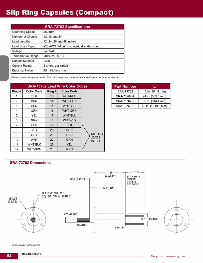
54 Moog • www.moog.com
Slip Ring Capsules (Compact)
*Please note that the operational life of the unit is dependent upon rotational speed, environment and temperature.
SRA-73762 SpecificationsOperating Speed 250 rpm*Number of Circuits 12, 18 and 24Lead Lengths 12, 24, 36 and 48 inchesLead Size / Type #28 AWG Teflon® insulated, stranded cond.Voltage 240 VACTemperature Range -40°C to +80°CContact Material GoldCurrent Rating 2 amps, per circuitElectrical Noise 60 milliohms max.
SRA-73762 Dimensions
Dimensions in inches (mm)
SRA-73762 Lead Wire Color CodesRing # Color Code Ring # Color Code
1 BLK 13 WHT-RED2 BRN 14 WHT-ORN3 RED 15 WHT-YEL4 ORN 16 WHT-GRN5 YEL 17 WHT-BLU6 GRN 18 WHT-VIO7 BLU 19 BLK8 VIO 20 BRN9 GRY 21 RED10 WHT 22 ORN11 WHT-BLK 23 YEL12 WHT-BRN 24 GRN
TAGGEDLEADS 19 - 24
Part Number “L”SRA-73762 12 in (304.8 mm)
SRA-73762-A 24 in (609.6 mm)SRA-73762-B 36 in (914.4 mm)SRA-73762-C 48 in (1219.2 mm)
REVISED 03/16

55Moog • www.moog.com 55
Slip Ring Capsules (Compact)
SRA-73574 / SRA-73587Compact in various circuit configurations
DescriptionA slip ring capsule can be used in any electromechanical system that requires unrestrained, intermittent, or continuous rotation while transferring power and / or data.
The SRA-73574 / SRA-73587 provides an economical, readily available solution when a compact, high circuit count configuration is required. Our standard units, offer 36, 2 amp, 4, 10 amp and 24, 2 amp signal rings, respectively. These units can be modified to provide various combinations of power, signal and coax circuits. Similar in design to our very popular AC6023, this design features gold-on-gold contact technology for ultimate performance in many challenging applications.
Features• 2 amp and 10 amp circuit combinations standard• Precision ball bearing for long life• Speeds up to 250 rpm• Compact size • Transfers analog and digital signals• Compatible with data bus protocols
Benefits• Unique signal handling performance with minimal electrical circuit noise• Tight packaging to fit in the most demanding space constraints• Low torque to minimize system torque budget• Rapid delivery
Typical Applications
• Pan / tilt camera mounts• Rotary index tables• Rate tables• Lighting• Robotics

56 Moog • www.moog.com
Slip Ring Capsules (Compact)
Specifications SRA-73574 SRA-73587Operating Speed 250 rpm* 250 rpm*Circuit Configurations 36 circuits @ 2 A., #26 AWG Teflon®
insulated, stranded cond.4 power 10 A continuous, #18 AWG Teflon® insulated, stranded cond. 24 signal, 2 A, #26 AWG Teflon insulated, stranded cond.
Voltage 240 VAC 240 VACTemperature Range -40°C to +80°C -40°C to +80°CContact Material Gold GoldElectrical Noise 60 milliohms max. 60 milliohms max.
*Please note that the operational life of the unit is dependent upon rotational speed, environment and temperature.
Dimensions in inches
SRA-73574 / SRA-73587 Dimensions
SRA-73574 Lead Wire Color CodesRing # Color
CodeRing # Color
CodeRing # Color
CodeRing # Color
Code1 BLK 10 WHT 19 WHT-GRY 28 WHT-BRN-RED2 BRN 11 WHT-BLK 20 WHT-BLK-BRN 29 WHT-BRN-ORN3 RED 12 WHT-BRN 21 WHT-BLK-RED 30 WHT-BRN-YEL4 ORN 13 WHT-RED 22 WHT-BLK-ORN 31 WHT-BRN-GRN5 YEL 14 WHT-ORN 23 WHT-BLK-YEL 32 WHT-BRN-BLU6 GRN 15 WHT-YEL 24 WHT-BLK-GRN 33 WHT-BRN-VIO7 BLU 16 WHT-GRN 25 WHT-BLK-BLU 34 WHT-BRN-GRY8 VIO 17 WHT-BLU 26 WHT-BLK-VIO 35 WHT-RED-ORN9 GRY 18 WHT-VIO 27 WHT-BLK-GRY 36 WHT-RED-YEL
SRA-73587 Lead Wire Color CodesRing # Color Code1 - 24 SAME AS SHOWN
ON SRA-7357425 WHT (18 AWG)26 BRN (18 AWG)27 RED (18 AWG)28 ORN (18 AWG)
Part Number “L”SRA-73574 / SRA-73587 12 in (304.8 mm)
SRA-73574-A / SRA-73587-A 24 in (609.6 mm)SRA-73574-B / SRA-73587-B 36 in (914.4 mm)SRA-73574-C / SRA-73587-C 48 in (1219.2 mm)
REVISED 03/16

57Moog • www.moog.com 57
Slip Ring Capsules (Compact)
AC6355Compact in various circuit configurations
DescriptionA slip ring capsule can be used in any electromechanical system that requires unrestrained, intermittent, or continuous rotation while transferring power and / or data.
The AC6355 provides an economical, readily available solution when a compact, high circuit count configuration is required. Our standard units, AC6355-36 and AC6355-56 offer 36, 2 amp and 56, 2 amp signal rings, respectively. These units can be modified to provide various combinations of power, signal and coax circuits. Similar in design to our very popular AC6023, this design features gold-on-gold contact technology for ultimate performance in many challenging applications.
Features• Standard 36 and 56 circuit models with 2 amp circuits• 2 amp, 5 amp, 10 amp circuit combinations standard; 50 or 75 ohm coax circuit combinations are optional• Precision ball bearing for long life• Speeds up to 250 rpm• Compact size• Sealed units available (dust and light splash only)• Metal housing available • Transfers analog and digital signals• Compatible with data bus protocols
Benefits• Unique signal handling performance with minimal electrical circuit noise• Tight packaging to fit in the most demanding space constraints• Low torque to minimize system torque budget• Rapid delivery
Typical Applications
• Pan / tilt camera mounts• Rotary index tables• Rate tables• Lighting• Robotics

58 Moog • www.moog.com
Slip Ring Capsules (Compact)
2 amp leads will be color coded and number tagged5 amp rings will have 20 AWG black lead wire, tagged10 amp rings will have 16 AWG black lead wire, tagged
Dimensions in inches (millimeters)
AC6355 Specifications OptionsOperating Speed 250 rpm* • 48 inch (1200 mm) lead length
• Aluminum housing, black anodized• 50 ohm coax, RG178• 75 ohm coax, RG179• Splash seals for dust and moisture resistance• Non-flanged housing available• IP 65 rated slip ring available (P/N AC7356)
Circuit Configurations 36 ring 56 ring36 @ 2 amp 56 @ 2 amp4 @ 5 amp; 28 @ 2 amp 4 @ 5 amp; 48 @ 2 amp4 @ 10 amp; 20 @ 2 amp 4 @ 10 amp; 40 @ 2 amp
Lead Length 24 inch (600 mm)Lead Size / Type 2 amp, 26 AWG
5 amp, 20 AWG 10 amp, 16 AWG
Housing PlasticVoltage 240 VACOperating Temp. -40°C to +80°CContact Material GoldElectrical Noise 60 milliohms max.
*Please note that the operational life of the unit is dependent upon rotational speed, environment and temperature.
AC6355 Lead Wire Color CodesRing
#Color Code
Ring #
Color Code
Ring #
Color Code
Ring #
Color Code
Ring #
Color Code
Ring #
Color Code
1 BLK 11 WHT-BLK 21 RED 31 WHT-RED 41 YEL 51 WHT-YEL2 BRN 12 WHT-BRN 22 ORN 32 WHT-ORN 42 GRN 52 WHT-GRN3 RED 13 WHT-RED 23 YEL 33 WHT-YEL 43 BLU 53 WHT-BLU4 ORN 14 WHT-ORN 24 GRN 34 WHT-GRN 44 VIO 54 WHT-VIO5 YEL 15 WHT-YEL 25 BLU 35 WHT-BLU 45 GRY 55 BLK6 GRN 16 WHT-GRN 26 VIO 36 WHT-VIO 46 WHT 56 BRN7 BLU 17 WHT-BLU 27 GRY 37 BLK 47 WHT-BLK8 VIO 18 WHT-VIO 28 WHT 38 BRN 48 WHT-BRN9 GRY 19 BLK 29 WHT-BLK 39 RED 49 WHT-RED
10 WHT 20 BRN 30 WHT-BRN 40 ORN 50 WHT-ORN
AC6355 A B56 Ring 3.50 in (88,9 mm) 2.96 (75,3)36 Ring 2.60 (66,04) 2.06 (52,4)
REVISED 3/17

59Moog • www.moog.com 59
AC7356** Specifications (IP 65 Sealed Version of AC6355)
Options
Operating Speed 250 rpm* • 48 inch (1200 mm) length leads• 50 ohm coax, RG178• 75 ohm coax, RG179
Circuit Configurations 36 ring 56 ring36 @ 2 amp 56 @ 2 amp4 @ 5 amp; 28 @ 2 amp 4 @ 5 amp; 48 @ 2 amp4 @ 10 amp; 20 @ 2 amp 4 @ 10 amp; 40 @ 2 amp
Lead Length 24 inch (600 mm)Lead Size / Type 2 amp, 26 AWG
5 amp, 20 AWG 10 amp, 16 AWG
Housing Aluminum housing, black anodizedVoltage 240 VACOperating Temp. -40°C to +80°CContact Material GoldElectrical Noise 60 milliohms max.Environmental IP 65 sealed
*Please note that the operational life of the unit is dependent upon rotational speed, environment and temperature.
**Product Replaced AC7038. Contact factory for details.
Slip Ring Capsules (Compact)
Dimensions in inches
AC7356** Dimensions
AC7356** “L”AC7356-36 2.495 in (63.4 mm)AC7356-56 3.395 in (86.2 mm)
REVISED 6/18

60 Moog • www.moog.com
Slip Ring Capsules (Compact)
AC6305AC6310Compact in various circuit configurations
DescriptionA slip ring can be used in any electromechanical system that requires unrestrained, continuous rotation while transferring power and / or data from a stationary to a rotating structure. A slip ring is also called a rotary electrical interface, commutator, collector, swivel or an electrical rotary joint.
The AC6305 provides three, 5 amp circuits combined with 6, 9, or 12 signal (2 amp max) circuits. The AC6310 provides three, 10 amp circuits and 3 or 6 signal circuits. This compact power and signal handling design provides unique capability for many challenging applications.
Features• 6, 9, 12 and 15 circuit models• 5 amp / 2 amp and 10 amp / 2 amp circuit combinations• Precision ball bearings meet or exceed life requirements for most commercial applications• Speeds up to 250 rpm• Compact size: 1.38 inch long• Gold• 12, 24, 36, 48 inch standard lead lengths (longer lead lengths are available)• Sealed units are also available (dust and light splash only)• Flexible silver-plated copper, color-coded, Teflon® insulated lead wires• Compatible with data bus protocols• Also available with 6, 12, 18, and 24, 2 amp rings. Please refer to AC6023 data sheet.
Benefits• Smooth running• Low torque• Compact• Very low noise (electrical)• Quick shipment
Typical Applications
• CCTV pan / tilt camera mounts• Electrical test equipment• Manufacturing and process control equipment - Indexing tables - Robotics (end-effectors, arms, vision systems, sensors)• Exhibit / display equipment• Medical equipment

61Moog • www.moog.com 61
Slip Ring Capsules (Compact)
Dimensions in inches (millimeters)
*Please note that the operational life of the unit is dependent upon rotational speed, environment and temperature.
AC6305 Lead Wire Color Codes AC6310 Lead Wire Color Codes
20 AWGTAGGEDLEADS
Ring # Color Code
Ring # Color Code
16 AWGTAGGEDLEADS
Ring # Color Code
Ring # Color Code
1 BLK 9 GRN 1 BLK 9 GRN2 BLK 10 BLU 2 BLK3 BLK 11 VIO 3 BLK4 BLK 12 GRY 4 BLK5 BRN 13 WHT 5 BRN6 RED 14 WHT-BLK 6 RED7 ORN 15 WHT-BRN 7 ORN8 YEL 8 YEL
AC6305 / AC6310 Dimensions
Specifications AC6305 AC6310 OptionsOperating Speed 250 rpm* 250 rpm* • Splash seals
for dust and moisture resistance• Metal housings with and without flanges
Number of Circuits 3 @ 5 amps and 6, 9, or 12 @ 2 amps 3 @ 10 amps and 3 or 6 @ 2 ampsLead Lengths 12, 24, 36 and 48 inches 12, 24, 36 and 48 inchesLead Size / Type 2 amp, 26 gauge silver plated copper, Teflon®
5 amp, 20 gauge silver plated copper, Teflon®2 amp, 26 gauge silver plated copper, Teflon®
10 amp,16 gauge tin plated copper, Teflon®
Voltage 240 VAC 240 VACMax Ambient Temp. -40°C to +80°C -40°C to +80°CContact Material Gold GoldCurrent Rating 5 amps and 2 amps / circuit 10 amps and 2 amps / circuitNoise 60 milliohms max. 60 milliohms max.
Part Number “A”AC6305 / AC6310 12 in (304.8 mm)
AC6305-A / AC6310-A 24 in (609.6 mm)AC6305-B / AC6310-B 36 in (914.4 mm)AC6305-C / AC6310-C 48 in (1219.2 mm)

62 Moog • www.moog.com
AC7094Fiber brush slip ring capsule
DescriptionA slip ring capsule can be used in any electromechanical system that requires unrestrained, intermittent or continuous rotation while transferring power and / or data. A slip ring is also called a rotary electrical joint, collector, commutator or swivel. A slip ring can improve system performance by simplifying operations and eliminating damage prone wires.
The AC7094 provides a compact 2.1 inch outside diameter. The AC7094 provides 5 amp circuits in 30, 36, 42 and 48 ring configurations. Similar in design to our very popular AC4598 and AC6200 series, this design features long life, fiber brush contact technology for ultimate performance in many challenging applications.
Features• Compact 2.1 inch outside diameter• Speeds up to 250 rpm• Multiple circuit configurations• Continuous rotation of power and / or data signals• High-impact thermoplastic construction• Gold plated rings• Available with Ethernet
Benefits• Transfers power, as well as analog and digital signals• Compatible with data bus protocols• Fiber brush technology provides long life and maintenance free
operation• Compact packaging
Typical Applications
• Precision rotary equipment• Semiconductor handling systems• Industrial machinery• Robotics
Slip Ring Capsules (Compact)

63Moog • www.moog.com 63
*Please note that the operational life of the unit is dependent upon rotational speed, environment and temperature.
AC7094 Specifications OptionsOperating Speed 250 rpm* • 24, 36 and 48 inch leads
• Longer leads available• Available with Ethernet, contact factory
Number of Circuits 30, 36, 42 or 48Lead Length 12 inch standardLead Size / Type 22 AWGVoltage 240 VACOperating Temp. -40°C to +80°CCurrent Rating 5 amps / circuitElectrical Noise 100 milliohms max.
AC7094 Dimensions
Wire Color CodeRing # Color Ring # Color Ring # Color Ring # Color Ring # Color
1 BLK 11 WHT / BLK 21 WHT / BLK / RED 31 BLU 41 WHT / BLU
2 BRN 12 WHT / BRN 22 WHT / BLK / ORN 32 VIO 42 WHT / VIO
3 RED 13 WHT / RED 23 WHT / BLK / YEL 33 GRY 43 WHT / GRY
4 ORN 14 WHT / ORN 24 WHT / BLK / GRN 34 WHT 44 WHT / BLK / BRN
5 YEL 15 WHT / YEL 25 BLK 35 WHT / BLK 45 WHT / BLK / RED
6 GRN 16 WHT / GRN 26 BRN 36 WHT / BRN 46 WHT / BLK / ORN
7 BLU 17 WHT / BLU 27 RED 37 WHT / RED 47 WHT / BLK / YEL
8 VIO 18 WHT / VIO 28 ORN 38 WHT / ORN 48 WHT / BLK / GRN
9 GRY 19 WHT / GRY 29 YEL 39 WHT / YEL
10 WHT 20 WHT / BLK / BRN 30 GRN 40 WHT / GRN
Part Number Dimension “A”AC7094-130 5.016 inch (127,4 mm)AC7094-136 5.574 (141,6)AC7094-142 6.132 (155,8)AC7094-148 6.690 (169,9)
Slip Ring Capsules (Compact)
Dimensions in inches
REVISED 01/16

64 Moog • www.moog.com
Slip Ring Capsules (Compact)
AC7036Integrated AC6349 and AC6355 / AC7195 slip ring capsules for high circuit density
DescriptionA slip ring capsule can be used in any electromechanical system that requires unrestrained, intermittent, or continuous rotation while transferring power and / or data.
The AC7036 integrates two of our popular slip ring capsules, the AC6349 and AC6355, creating one compact assembly. Connecting hardware is used to combine these units by inserting the AC6355 / AC7195 in the bore of the AC6349. This combination provides a wide range of circuit capabilities up to 24 circuits rated at 15 amps and 36 or 56 circuits rated at 2 amps, in a compact 6.5 inch length and 3.1 inch diameter. The outer capsule features 6, 12, 18, or 24 circuits rated at 15 amps, while the inner capsule can be configured with 2 amp, 5 amp, 10 amp, or coax circuits.
Features• Multiple circuit combinations• High circuit density• Precious metal contacts• Speeds to 150 rpm• Flying leads• Rugged black anodized aluminum construction• Available with Ethernet
Benefits• Isolations between power (outer) and signal (inner)• Tight packaging to fit the most demanding applications• Low torque• Built from readily available components for rapid delivery • Rotor flange for ease of mounting
Typical Applications
• Gimble systems• Packaging equipment• Rotary tables• Motion control systems• Robotics
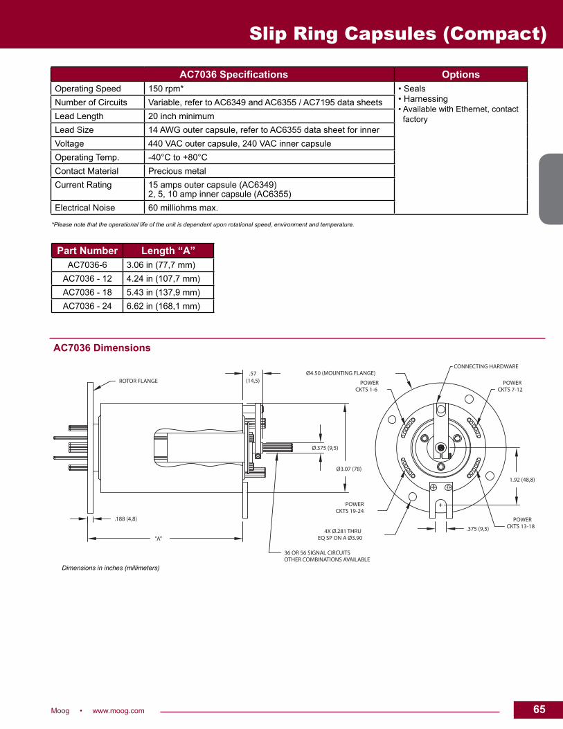
65Moog • www.moog.com 65
Slip Ring Capsules (Compact)
Part Number Length “A”AC7036-6 3.06 in (77,7 mm)
AC7036 - 12 4.24 in (107,7 mm)AC7036 - 18 5.43 in (137,9 mm)AC7036 - 24 6.62 in (168,1 mm)
AC7036 Specifications OptionsOperating Speed 150 rpm* • Seals
• Harnessing• Available with Ethernet, contact factory
Number of Circuits Variable, refer to AC6349 and AC6355 / AC7195 data sheetsLead Length 20 inch minimumLead Size 14 AWG outer capsule, refer to AC6355 data sheet for innerVoltage 440 VAC outer capsule, 240 VAC inner capsuleOperating Temp. -40°C to +80°CContact Material Precious metalCurrent Rating 15 amps outer capsule (AC6349)
2, 5, 10 amp inner capsule (AC6355)Electrical Noise 60 milliohms max.
AC7036 Dimensions
*Please note that the operational life of the unit is dependent upon rotational speed, environment and temperature.
Ø4.50 (MOUNTING FLANGE)
.188 (4,8)
4X Ø.281 THRUEQ SP ON A Ø3.90
Ø3.07 (78)
.57(14,5)
Ø.375 (9,5)
"A"
1.92 (48,8)
.375 (9,5)
CKTS 1-6 CKTS 7-12
CKTS 13-18
CKTS 19-24
POWER POWER
POWER
POWER
CONNECTING HARDWARE
ROTOR FLANGE
36 OR 56 SIGNAL CIRCUITSOTHER COMBINATIONS AVAILABLE
Dimensions in inches (millimeters)
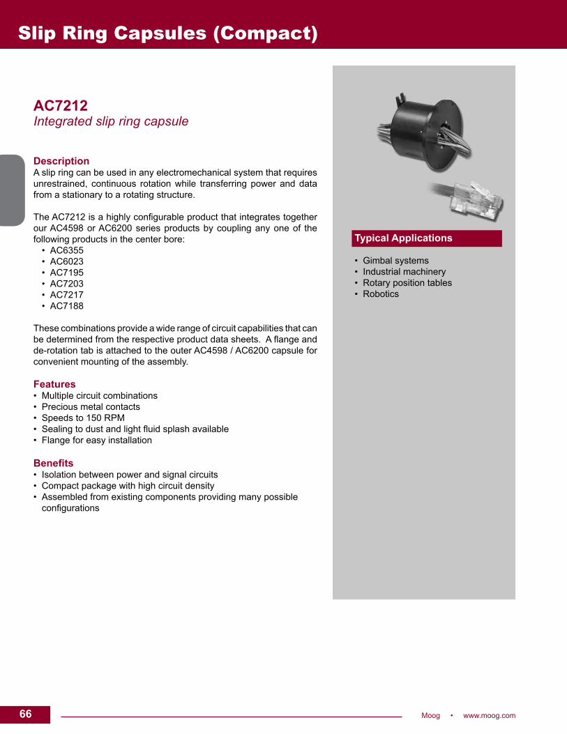
66 Moog • www.moog.com
AC7212Integrated slip ring capsule
DescriptionA slip ring can be used in any electromechanical system that requires unrestrained, continuous rotation while transferring power and data from a stationary to a rotating structure.
The AC7212 is a highly configurable product that integrates together our AC4598 or AC6200 series products by coupling any one of the following products in the center bore: • AC6355 • AC6023 • AC7195 • AC7203 • AC7217 • AC7188
These combinations provide a wide range of circuit capabilities that can be determined from the respective product data sheets. A flange and de-rotation tab is attached to the outer AC4598 / AC6200 capsule for convenient mounting of the assembly.
Features• Multiple circuit combinations• Precious metal contacts• Speeds to 150 RPM• Sealing to dust and light fluid splash available • Flange for easy installation
Benefits• Isolation between power and signal circuits• Compact package with high circuit density• Assembled from existing components providing many possible
configurations
Typical Applications • Gimbal systems• Industrial machinery• Rotary position tables• Robotics
Slip Ring Capsules (Compact)

67Moog • www.moog.com 67
AC7212 Specifications OptionsOperating Speed 150 rpm* continuous • Splash seals for dust and light fluid splash
• Variable lead lengths, see individual sheets for options
Circuit Options Refer to AC4598 or AC6200 data sheets for outer capsule options and AC6355, AC6023, AC7195, AC7203, AC7188 data sheets for inner capsule options
Voltage Refer to individual product data sheets
Temperature Range -40°C to +80°C
Contact Material Precious metal
Current Rating Signal to 10 amps
AC7212 Dimensions
*Please note that the operational life of the unit is dependent upon rotational speed, environment and temperature.
Dimensions in inches [mm]
To determine “L” dimension refer to AC4598 / AC6200 data sheet for length of the selected outer slip ring configuration
Slip Ring Capsules (Compact)

68 Moog • www.moog.com
P SeriesCompact slip rings
DescriptionThe P series slip rings are compact, cost effective mercury free sliprings designed for industrial manufacturing. The P2 has two rings,each able to carry 7 amps. The P4 has two rings rated at 7 amps andtwo at 2 amps. All are fully ball raced and suitable for mounting in anyorientation. The P2+ and P4+ are capable of conducting 14 ampsthrough the power circuits and in the case of the P4+, 2 amps throughthe 2 signal circuits. These units are ideal for applications where currentsare increased due to lower distribution voltage. They are well suitedfor use in the food and packaging industries. The P8 Lite is capable ofcarrying 14 amps on each of the 8 rings. All P Series units feature goldslip rings and gold alloy brushes. Standard spade terminals or flyingleads allow rapid installation.
Features• Mercury free• Reliable rotational connections for power,
signal and data transmission• Speeds to 600 rpm• Fast on spade terminals or flying leads
Benefits• Compact and robust design• Designed for low cost• Gold contacts• Mount in any orientation
Typical Applications
• Machine tools• Heated rollers• Food manufacturing• Chemical processing• Packaging
Slip Ring Capsules (Compact)

69Moog • www.moog.com 69
P Series Dimensions
P Series SpecificationsP2 P4 P2+ P4+ P8 Lite
Part Number 80050-957 /1028300-2
80050-958 / 1028300-4
80050-956 80050-955 80059-950
Maximum Speed 400 rpm 400 rpm 400 rpm 400 rpm 600 rpmPower Circuits 2 @ 7 amps 2 @ 7 amps 2 @ 14 amps 2 @ 14 amps 8 @ 14 ampsSignal Circuits - 2 @ 2 amps - 2 @ 2 amps -Terminals Power 0.8 x 6.35 0.8 x 6.35
0.8 x 2.800.8 x 6.35 0.8 x 6.35
0.8 x 2.80ETFE Flying Leads
Power 16 AWG[PARA]
Mounting As Shown On DrawingMaximum Voltage 240 VAC 240 VAC 240 VAC 240 VAC 240 VACTemperature Range
-20°C to +90°C -20°C to +90°C -20°C to +90°C -20°C to +90°C -20°C to +80°C
Sealing - - - - IP22
Dimensions in millimeters [inches]
Slip Ring Capsules (Compact)
*Please note that the operational life of the unit is dependent upon rotational speed, environment and temperature.
P2, P2+, P4, P4+ Series P8 Lite Series

70 Moog • www.moog.com
Ethernet and High Definition Slip Ring Capsules
Ethernet and High Definition Slip RingsHigh performance slip ring solutions for reliable Ethernet transmission
DescriptionEthernet, developed in 1976, has become the primary LAN technology and serves as the basis for the IEEE 802.3 standard. Ethernet provides significant advantage as a robust, inexpensive and widely supported format leading to its implementation in a wide variety of data communication networks.
Moog’s Ethernet slip ring solutions have been developed to provide reliable products to allow transfer of the Ethernet protocol through a rotating interface. The innovative designs meet the challenge of matching impedance, controlling crosstalk and managing losses. Wide range of product solutions are offered with combinations of data and power in multiple mechanical configurations to meet your application needs. Advantages • Configured for Ethernet transmission• RJ45 connector for direct plug-and-play• High performance contact technology• Available with multiple Ethernet, power and signal combinations
Selecting A Slip Ring There are three important parameters that must be considered when incorporating a slip ring in an Ethernet communication line: 1. Insertion loss 2. Return loss 3. Crosstalk
These parameters establish the signal to noise ratio of the transmission line and ultimately the capability of the slip ring to handle critical data communication. Equally important is the durability of the contacts to maintain integrity over time for long term performance to specification. As the world’s leading manufacturer of slip rings, Moog slip rings are uniquely suited for critical Ethernet applications. Founded over 50 years ago, the company has developed products for critical applications in military, space, medical and industrial environments. Our industrial slip ring products are based on our years of material and design experience and provide unrivaled contact technologies. To respond to market demand for engineered Ethernet solutions, Moog has developed an extensive line of Ethernet products based on our popular capsule and through-bore products.
Typical Applications • 10 / 100 / 1000BaseT transmission• Motion control• Video over Ethernet• CCTV IP-surveillance

71Moog • www.moog.com 71
SRA-73799 / SRA-73806Ethernet slip ring capsule
DescriptionA slip ring can be used in any electromechanical system that requires unrestrained, continuous rotation while transferring power and data from a stationary to a rotating structure.
The SRA-73799 and SRA-73806, derivative of our very popular SRA-73625, provides 100BaseT or 1000BaseT Ethernet communication in combination with 2 amp, signal / power connections. The Ethernet cable is supplied terminated with a RJ45 jack, ready to connect.
The SRA-73799 and SRA-73806 utilizes gold-on-gold contact technology with very low electrical noise for unparalleled performance and provides functional life that exceeds any competitive slip ring.
Features• Fully compliant with IEEE 802.3 formats - 10BaseT - 100BaseTx - 100BaseT2 - 1000BaseT• Speeds up to 250 RPM continuous• 12, 24, 36 and 48 inch lead lengths• Supplied with 100BaseT or 1000BaseT Ethernet
and 2 amp circuits
Benefits• Compact• Plug-and-play Ethernet connection
Typical Applications • Video over Ethernet• Motor control• POE (Power-Over-Ethernet)• CCTV IP-surveillance
Ethernet and High Definition Slip Ring Capsules

72 Moog • www.moog.com
Ethernet and High Definition Slip Ring Capsules
SRA-73799 / SRA-73806 Specifications OptionsOperating Speed 250 rpm* continuous • Lead lengths of 12, 24, 36 and 48 inches
Ethernet Connections 10 / 100BaseT and 1000BaseT
Circuit Options Ethernet plus, 2 amp contacts
Voltage 240 VAC on power circuits
Temperature Range -40°C to +80°C
Contact Material Gold-on-gold
Current Rating 2 amps
SRA-73799 / SRA-73806 Dimensions
*Please note that the operational life of the unit is dependent upon rotational speed, environment and temperature.
SRA-73799 Lead Wire ColorRing # Color Code Ring # Color Code
1
1000BaseT Ethernet Cable
9 BLK
2 10 BRN
3 11 RED
4 12 ORN
5 13 YEL
6 14 GRN
7
8
Dimensions in inches (mm)
SRA-73806 Lead Wire ColorRing # Color Code Ring # Color Code
1100BaseT
Ethernet Cable
9 YEL
2 10 GRN
3 11 BLU
4 12 VIO
5 BLK 13 GRY
6 BRN
7 RED
8 ORN

73Moog • www.moog.com 73
Ethernet and High Definition Slip Ring Capsules
SRA-73798 / SRA-73805Ethernet slip ring capsule
DescriptionA slip ring can be used in any electromechanical system that requires unrestrained, continuous rotation while transferring power and data from a stationary to a rotating structure.
The SRA-73798 and SRA-73805 provide 100BaseT or 1000BaseT Ethernet communication in combination with 2 amp, signal / power connections. The Ethernet cable is supplied terminated with a RJ45 jack, ready to connect.
The SRA-73798 and SRA-73805 utilize gold-on-gold contact technology with very low electrical noise for unparalleled performance and provides functional life that exceeds any competitive slip ring.
Features• Fully compliant with IEEE 802.3 formats - 10BaseT - 100BaseTx - 100BaseT2 - 1000BaseT• Speeds up to 250 RPM continuous• 12, 24, 36 and 48 inch lead lengths• Supplied with 100BaseT or 1000BaseT Ethernet
and 2 amp circuits
Benefits• Compact• Plug-and-play Ethernet connection
Typical Applications • Video over Ethernet• Motor control• POE (Power-Over-Ethernet)• CCTV IP-surveillance

74 Moog • www.moog.com
Ethernet and High Definition Slip Ring Capsules
SRA-73798 / SRA-73805 Specifications OptionsOperating Speed 250 rpm* continuous • Standard 12 inch lead lengths, optional 24, 36 and
48 inch availableEthernet Connections 10 / 100BaseT and 1000BaseT
Circuit Options Ethernet plus, 2 amp contacts
Voltage 210 VAC on power circuits
Temperature Range -40°C to +80°C
Contact Material Gold-on-gold
Current Rating 2 amps
SRA-73798 / SRA-73805 Dimensions
*Please note that the operational life of the unit is dependent upon rotational speed, environment and temperature.
SRA-73798 Lead Wire ColorRing # Color Code Ring # Color Code
1
1000BaseT Ethernet Cable
11 RED
2 12 ORN
3 13 YEL
4 14 GRN
5 15 BLU
6 16 VIO
7 17 GRY
8 18 WHT
9 BLK 19 WHT-BLK
10 BRN 20 WHT-BRN
Dimensions in inches (mm)
SRA-73805 Lead Wire ColorRing # Color Code Ring # Color Code
1100BaseT
Ethernet Cable
11 BLU
2 12 VIO
3 13 GRY
4 14 WHT
5 BLK 15 WHT-BLK
6 BRN 16 WHT-BRN
7 RED
8 ORN
9 YEL
10 GRN

75Moog • www.moog.com 75
Ethernet and High Definition Slip Ring Capsules
AC7203Ethernet slip ring capsule
DescriptionA slip ring can be used in any electromechanical system that requires unrestrained, continuous rotation while transferring power and data from a stationary to a rotating structure.
The AC7203, a derivative of our very popular AC6023 series, provides Ethernet communication in combination with 2 amp, 5 amp and 10 amp power connections. Options are available for both 10 / 100BaseT and 1000BaseT (Gigabit Ethernet). The Ethernet cable is supplied terminated with a RJ45 jack, ready to connect.
The AC7203 utilizes gold-on-gold contact technology with very low electrical noise for unparalleled performance and provides functional life that exceeds any competitive slip ring.
Features• Fully compliant with IEEE 802.3 formats - 10BaseT - 100BaseTx - 100BaseT2 - 1000BaseT• Speeds up to 250 RPM continuous• 12, 24, 36 and 48 inch lead lengths• Available with various combinations of Ethernet,
2 amp, 5 amp and 10 amp connections• Sealing to dust and light fluid splash available
Benefits• Compact• Plug-and-play Ethernet connection
Typical Applications • Video over Ethernet• Motor control• POE (Power-Over-Ethernet)• CCTV IP-surveillance
Up to 2X

76 Moog • www.moog.com
Ethernet and High Definition Slip Ring Capsules
AC7203 Specifications OptionsOperating Speed 250 rpm* continuous • Splash seals for dust and light fluid splash
• Standard 12 inch lead lengths, optional 24, 36 and 48 inch available• No flange• Metal housing
Ethernet Connections 10 / 100BaseT and 1000BaseT
Circuit Options Ethernet plus, 2 amp, 5 amp and 10 amp
Voltage 240 VAC on power circuits
Temperature Range -40°C to +80°C
Contact Material Gold-on-gold
Current Rating 2 to 10 amps
AC7203 Dimensions
*Please note that the operational life of the unit is dependent upon rotational speed, environment and temperature.
Part Number Length “L”AC7203-6 .57 inch (14.5 mm)
AC7203-12 .84 inch (21.3 mm)
AC7203-18 1.11 inch (28.2 mm)
AC7203-24 1.38 inch (35.1 mm)
Circuit TablePart # Continuous Current (amps) Ethernet
2 5 10 100BaseT 1000BaseT (or 2 100BaseT)AC7203-6 1
AC7203-12 6 1
AC7203-12V 2 1
AC7203-12G 1
AC7203-18 12 1
AC7203-18V 6 2 1
AC7203-18X 2 2 1
AC7203-18G 6 1
AC7203-18GV 2 1
AC7203-24 18 1
AC7203-24V 12 2 1
AC7203-24X 8 2 1
AC7203-24G 12 1
AC7203-24GV 6 2 1
AC7203-24GX 2 2 1
AC7203-24GG 2
Dimensions in inches [mm]
NOTE: Contact factory for details on wire colors

77Moog • www.moog.com 77
Ethernet and High Definition Slip Ring Capsules
AC7188High Definition (HD) video slip ring capsule
DescriptionA slip ring can be used in any electromechanical system that requires unrestrained, continuous rotation while transferring video, power and data from a stationary to a rotating structure.
The AC7188, a derivative of our very popular AC6023 series, provides HD-SDI video communication in combination with 2 amp and 5 amp power or data connections. RG179 coax cable is provided for video transfer. The coax cable is supplied terminated with a BNC connector, ready to install.
The AC7188 utilizes gold-on-gold contact technology with very low electrical noise for un-paralleled performance and provides functional life that exceeds any competitive slip ring.
Features• Compatible with: - SMPTE 259 M (SD-SDI) - SMPTE 292 M (HD-SDI)• Speeds up to 250 RPM• 12, 24, 36 and 48 inch lead lengths• Available with various combinations of coax, 2 amp
and 5 amp connections• Sealing to dust and light fluid splash available
Benefits• Compact• Plug-and-play coax connection
Typical Applications • Security cameras• Rotating video displays• Camera jibs• Pan / tilt video camera heads

78 Moog • www.moog.com
Ethernet and High Definition Slip Ring Capsules
AC7188 Specifications OptionsOperating Speed 250 rpm* • Seals for dust and light fluid splash
• Lead lengths of 12, 24, 36 and 48 inches• Flange / no flange• Metal housing
Video Connections HD-SDI
Circuit Options Video, 2 amp and 5 amp
Voltage 210 VDC / 240 VAC on standard circuits
Temperature Range -40°C to +80°C
Contact Material Gold
Current Rating 2 amp (28 AWG) and 5 amp (20 AWG)
AC7188 Dimensions
*Please note that the operational life of the unit is dependent upon rotational speed, environment and temperature.
Circuit TablePart # Continuous Current
(amps)HD-SDI
2 5 RG179AC7188-18 8 1
AC7188-18V 2 2 1
AC7188-24 14 1
AC7188-24V 8 2 1
Dimensions in inches [mm]
Lead WireAC7188-18 AC7188-18V AC7188-24 AC7188-24V
Ring #
Color / AWG Ring #
Color / AWG Ring #
Color / AWG Ring #
Color / AWG
1 BLK / 28 1 BLK / 20 AWG 1 BLK / 28 1 BLK / 20
2 BRN / 28 2 ORN / 28 AWG 2 BRN / 28 2 BLK / 20
3 RED / 28 AWG 3 COAX 3 RED / 28 3 BLU / 28
4 ORN / 28 AWG 4 YEL / 28 AWG 4 ORN / 28 4 VIO / 28
5 COAX 5 BLK / 20 AWG 5 YEL / 28 5 COAX
6 YEL / 28 AWG 6 GRN / 28 6 GRY / 28
7 GRN / 28 AWG 7 BLU / 28 7 WHT / 28
8 BLU / 28 AWG 8 VIO / 28 8 WHT / BLK / 28
9 VIO / 28 AWG 9 COAX 9 WHT / BRN / 28
10 GRY / 28 10 WHT / RED / 28
11 WHT / 28 11 WHT / ORN / 28
12 WHT / BLK / 28
13 WHT / BRN / 28
14 WHT / RED / 28
15 WHT / ORN / 28
Part Number Length “L”AC7188-18 / 18V 1.105 inch (28.1 mm)
AC7188-24 / 24V 1.375 inch (34.9 mm)
Part Number Lead LengthAC7188 12 in (304.8 mm)
AC7188-A 24 in (609.6 mm)
AC7188-B 36 in (914.4 mm)
AC7188-C 48 in (1219.2 mm)

79Moog • www.moog.com 79
Lead WireAC7188-18 AC7188-18V AC7188-24 AC7188-24V
Ring #
Color / AWG Ring #
Color / AWG Ring #
Color / AWG Ring #
Color / AWG
1 BLK / 28 1 BLK / 20 AWG 1 BLK / 28 1 BLK / 20
2 BRN / 28 2 ORN / 28 AWG 2 BRN / 28 2 BLK / 20
3 RED / 28 AWG 3 COAX 3 RED / 28 3 BLU / 28
4 ORN / 28 AWG 4 YEL / 28 AWG 4 ORN / 28 4 VIO / 28
5 COAX 5 BLK / 20 AWG 5 YEL / 28 5 COAX
6 YEL / 28 AWG 6 GRN / 28 6 GRY / 28
7 GRN / 28 AWG 7 BLU / 28 7 WHT / 28
8 BLU / 28 AWG 8 VIO / 28 8 WHT / BLK / 28
9 VIO / 28 AWG 9 COAX 9 WHT / BRN / 28
10 GRY / 28 10 WHT / RED / 28
11 WHT / 28 11 WHT / ORN / 28
12 WHT / BLK / 28
13 WHT / BRN / 28
14 WHT / RED / 28
15 WHT / ORN / 28
Ethernet and High Definition Slip Ring Capsules
SRA-73810High Definition (HD) video slip ring capsule
DescriptionA slip ring can be used in any electromechanical system that requires unrestrained, continuous rotation while transferring video, power and data from a stationary to a rotating structure.
The SRA-73810, provides HD-SDI communication in combination with 12, 2 amp connections. RG179 coax cable is provided for video transfer. The coax cable is supplied terminated with BNC connectors, ready to install.
The SRA-73810 utilizes gold-on-gold contact technology with very low electrical noise for un-paralleled performance and provides functional life that exceeds any competitive slip ring.
Features• Compatible with: - SMPTE 259 M (SD-SDI) - SMPTE 292 M (HD-SDI)• Speeds up to 250 RPM• 12, 24, 36 and 48 inch lead lengths• Available with one coax, and 12, 2 amp connections
Benefits• Compact• Plug-and-play coax connection
Typical Applications • Security cameras• Rotating video displays• Camera jibs• Pan / tilt video camera heads

80 Moog • www.moog.com
Ethernet and High Definition Slip Ring Capsules
SRA-73810 Specifications OptionsOperating Speed 250 rpm* • Lead lengths of 12, 24, 36 and 48 inches
• Flange / no flangeVideo Connections HD-SDI / SD-SDI
Circuit Options Video, 12, 2 amp
Voltage 210 VDC / 240 VAC on standard circuits
Temperature Range -40°C to +80°C
Contact Material Gold
Current Rating 2 amp (28 AWG)
SRA-73810 Dimensions
*Please note that the operational life of the unit is dependent upon rotational speed, environment and temperature.
Lead Wire Color CodeRing # Color Code Ring # Color Code
1 BLK 9 GRY
2 BRN 10 WHT
3 RED 11 WHT-BLK
4 ORN 12 WHT-BRN
5 YEL 13 SHIELD
6 GRN 14 COAX
7 BLU 15 SHIELD
8 VIO
Dimensions in inches
REVISED 03/15

81Moog • www.moog.com 81
Ethernet and High Definition Slip Ring Capsules
SRA-73811High Definition (HD) dual channel video slip ring capsule
DescriptionA slip ring can be used in any electromechanical system that requires unrestrained, continuous rotation while transferring video, power and data from a stationary to a rotating structure.
The SRA-73811, provides dual HD-SDI communication in combination with 4, 2 amp connections. RG179 coax cable is provided for video transfer. The coax cable is supplied terminated with BNC connectors, ready to install.
The SRA-73811 utilizes gold-on-gold contact technology with very low electrical noise for un-paralleled performance and provides functional life that exceeds any competitive slip ring.
Features• Compatible with: - SMPTE 259 M (SD-SDI) - SMPTE 292 M (HD-SDI)• Speeds up to 250 RPM• 12, 24, 36 and 48 inch lead lengths• Available with two coax, and 4, 2 amp connections
Benefits• Compact• Plug-and-play coax connection
Typical Applications • Security cameras• Rotating video displays• Camera jibs• Pan / tilt video camera heads

82 Moog • www.moog.com
Ethernet and High Definition Slip Ring Capsules
SRA-73811 Specifications OptionsOperating Speed 250 rpm* • Lead lengths of 12, 24, 36 and 48 inches
• Flange / no flangeVideo Connections HD-SDI / SD-SDI
Circuit Options 2 Video, 4, 2 amp
Voltage 210 VDC / 240 VAC on standard circuits
Temperature Range -40°C to +80°C
Contact Material Gold
Current Rating 2 amp (26 AWG)
SRA-73811 Dimensions
*Please note that the operational life of the unit is dependent upon rotational speed, environment and temperature.
Lead Wire Color CodeRing # Color Code Tag # Circuit #
1 SHIELDC - 1 12 COAX
3 SHIELD
4 BLK - 2
5 BRN - 3
6 RED - 4
7 ORN - 5
8 SHIELDC - 2 69 COAX
10 SHIELD
Dimensions in inches

83Moog • www.moog.com 83
Ethernet and High Definition Slip Ring Capsules
AC7195Ethernet and High Definition (HD) video slip ring capsule
DescriptionA slip ring can be used in any electromechanical system that requires unrestrained, continuous rotation while transferring video, power and data from a stationary to a rotating structure.
The AC7195, a derivative of our very popular AC6355 series, provides Ethernet and HD-SDI video communication in combination with 2 amp, 5 amp and 10 amp power or data connections and analog coax connections. The Ethernet cable is supplied terminated with a RJ45 connector, and the HD-SDI cable is terminated with a BNC connector, ready to install.
The AC7195 utilizes gold-on-gold contact technology with very low electrical noise for un-paralleled performance and provides functional life that exceeds any competitive slip ring.
Features• Compliant with IEEE 802.3 formats - 10BaseT - 100BaseTx - 100BaseT2 - 1000BaseT• Compatible with HD-SDI• Speeds up to 250 RPM• 24 and 48 inch lead lengths• Multiple circuit configurations available• Sealing to dust and light fluid splash available
Benefits• Compact• Plug-and-play Ethernet and HD-SDI video connection
Typical Applications • Video over Ethernet• Motor control• POE (Power-Over-Ethernet)• High definition video security• Pan / tilt systems• Rotating high definition video displays
Up to 3X

84 Moog • www.moog.com
Ethernet and High Definition Slip Ring CapsulesAC7195 Specifications Options
Operating Speed 250 rpm* • Splash seals for dust and light fluid splash• Standard 24 inch lead lengths, optional 48 inch available• No flange• Metal housing• IP 65 rated slip ring available (see P/N AC7356 for dimensions)
Ethernet Connections 10 / 100BaseT and 1000BaseT
video Connections HD-SDI, 50 / 75 ohm coax
Circuit Options Ethernet plus coax, 2 amp, 5 amp and 10 amp
Voltage 240 VAC on power circuits
Temperature Range -40°C to +80°C
Contact Material Gold
Current Rating 2 to 10 amps
AC7195 Dimensions
*Please note that the operational life of the unit is dependent upon rotational speed, environment and temperature.
Dimensions in inches [mm]
NOTE: Contact factory for details on wire colors
Circuit TablePart # Continuous Current (amps) Coaxial Ethernet
2 5 10 RG178 RG179 HD-SDI 1000BaseT (or 2 100BaseT)AC7195-CC 23 4 1
AC7195-CG 20 2 2
AC7195-CH 23 2 1 1
AC7195-CK 23 2 2 1
AC7195-CN 33 2 1
AC7195-CV 25 4 2 1
AC7195-CX 25 2 2 1
AC7195-GG 17 3
AC7195-GH 20 1 2
AC7195-GK 20 2 2
AC7195-GN 30 2
AC7195-GV 22 4 2
AC7195-GX 22 2 2
AC7195-HH 23 2 1
AC7195-HK 23 2 1 1
AC7195-HN 33 1 1
AC7195-HV 25 4 1 1
AC7195-HX 25 2 1 1
AC7195-KK 23 4 1
AC7195-KN 33 2 1
AC7195-KV 25 4 2 1
AC7195-KX 25 2 2 1
AC7195-NN 43 1
AC7195-NV 35 4 1
AC7195-NX 35 2 1
AC7195-VV 27 8 1
AC7195-VX 27 4 2 1
AC7195-XX 27 4 1
REVISED 04/18

85Moog • www.moog.com 85
Ethernet and High Definition Slip Ring Capsules
AC7217Ethernet and High Definition (HD) video slip ring capsule
DescriptionA slip ring can be used in any electromechanical system that requires unrestrained, continuous rotation while transferring video, power and data from a stationary to a rotating structure.
The AC7217, a derivative of our very popular AC6355 series, provides Ethernet and HD-SDI video communication in combination with 2 amp, 5 amp and 10 amp power or data connections and analog coax connections. The Ethernet cable is supplied terminated with a RJ45 connector, and the HD-SDI cable is terminated with a BNC connector, ready to install.
The AC7217 utilizes gold-on-gold contact technology with very low electrical noise for unparalleled performance and provides functional life that exceeds any competitive slip ring.
Features• Compliant with IEEE 802.3 formats: - 10BaseT - 100BaseTx
- 100BaseT2 - 1000BaseT• Compatible with HD-SDI• Speeds up to 250 RPM• 24 and 48 inch lead lengths• Multiple circuit configurations available• Sealing to dust and light fluid splash available
Benefits• Compact• Plug-and-play Ethernet and HD-SDI video connection
Typical Applications • Video over Ethernet• Motor control• POE (Power-Over-Ethernet)• High definition video security• Pan / tilt systems• Rotating high definition video displays
Up to 3X

86 Moog • www.moog.com
Ethernet and High Definition Slip Ring Capsules
AC7217 Specifications OptionsOperating Speed 250 rpm* • Seals for dust and light fluid splash
• Standard 24 inch leads, optional 48 inch• No flange• Metal housing• IP 65 rated slip ring available (see P/N AC7356 for dimensions)
Ethernet Connections 10 / 100BaseT and 1000BaseT
Video Connections HD-SDI, 50 / 75 ohm coax
Circuit Options Ethernet plus, coax, 2 amp, 5 amp and 10 amp
Voltage 240 VAC on power circuits
Temperature Range -40°C to +80°C
Contact Material Gold
Current Rating 2 to 10 amps
AC7217 Dimensions
*Please note that the operational life of the unit is dependent upon rotational speed, environment and temperature.
Circuit TablePart # Continuous Current (amps) Coaxial Ethernet
2 5 10 RG178 RG179 HD-SDI 1000BaseT (or 2 100BaseT)AC7217-C 13 2 1
AC7217-H 13 1 1
AC7217-N 23 1
AC7217-G 10 2
AC7217-K 13 2 1
AC7217-V 15 4 1
AC7217-X 15 2 1
Dimensions in inches [mm]
NOTE: Contact factory for details on wire colors
REVISED 10/17

87Moog • www.moog.com 87
Ethernet and High Definition Slip Ring Capsules
SRA-73801 / SRA-73808Ethernet slip ring capsule
DescriptionA slip ring can be used in any electromechanical system that requires unrestrained, continuous rotation while transferring power and data from a stationary to a rotating structure.
The SRA-73801 and SRA-73808, derivatives of our very popular SRA-73683, provides Ethernet communication in combination with 2 amp, signal / power connections. The Ethernet cable is supplied terminated with a RJ45 jack, ready to connect.
The SRA-73801 and SRA-73808 utilize gold-on-gold contact technology with very low electrical noise for unparalleled performance and provides functional life that exceeds any competitive slip ring. This unit provides a 1/2 inch through-bore for shaft mounting and a compact 1-3/8 inch outside diameter for minimal space applications.
Features• Fully compliant with IEEE 802.3 formats - 10BaseT - 100BaseTx - 100BaseT2 - 1000BaseT• Speeds up to 120 RPM continuous• 12, 24, 36 and 48 inch lead lengths• Supplied with 1000BaseT Ethernet and 12, 2-amp circuits
Benefits• Compact• Plug-and-play Ethernet connection
Typical Applications • Video over Ethernet• Motor control• POE (Power-Over-Ethernet)• CCTV IP-surveillance

88 Moog • www.moog.com
Ethernet and High Definition Slip Ring Capsules
SRA-73801 / SRA-73808 Specifications OptionsOperating Speed 250 rpm* continuous • Lead lengths of 12, 24, 36 and 48 inches
Ethernet Connections 10 / 100BaseT and 1000BaseT
Circuit Options Ethernet plus, 2 amp contacts
Voltage 210 VDC on power circuits
Temperature Range -40°C to +80°C
Contact Material Gold
Current Rating 2 amps
SRA-73801 / SRA-73808 Dimensions
*Please note that the operational life of the unit is dependent upon rotational speed, environment and temperature.
Dimensions in inches [mm]
SRA-73801 Lead Wire ColorRing # Color Code Ring # Color Code
1
1000BaseT Ethernet Cable
11 RED
2 12 ORG
3 13 YEL
4 14 GRN
5 15 BLU
6 16 VIO
7 17 GRY
8 18 WHT
9 BLK 19 WHT-BLK
10 BRN 20 WHT-BRN
SRA-73808 Lead Wire ColorRing # Color Code Ring # Color Code
1100BaseT
Ethernet Cable
11 BLU
2 12 VIO
3 13 GRY
4 14 WHT
5 BLK 15 WHT-BLK
6 BRN 16 WHT-BRN
7 RED
8 ORN
9 YEL
10 GRN
REVISED 05/17

89Moog • www.moog.com 89
Ethernet and High Definition Slip Ring Capsules
Ethernet Through-bore Slip Ring Capsule OptionsMoog also offers Ethernet capability in the following through-bore slip ring capsules:
AC64381/2 inch through-bore miniature slip ring capsule
AC63491 inch through-bore various circuit configurations
AC4598 10 amp per circuit 1-1/2 inch through-bore
AC62001-1/2 inch through-bore 12, 24, 36 and 48 circuit versions
AC64281-3/8 inch through-bore in 60, 72, 84 and 96, 2 amp circuit versions
AC64291-3/8 inch through-bore in 48, 2 amp circuits and 6 or 12, 10 amp circuits
AC62752-3/4 inch through-bore
Please refer to the data sheets for additional information and contact factory for details.

90 Moog • www.moog.com
High Speed Slip Ring Capsules
PH Series
DescriptionSuitable for industrial applications such as general purpose instrumentation and testing, the PH series rugged design makes it an optimum choice for adverse operating conditions. Continuous silver connection ensuring minimal thermal error making this design compatible with thermocouple and strain gauge instrumentation. Quick and easy to install, these units are available with either 8 or 12 circuits. Both options operate at speeds up to 20,000 rotations per minute.
Features• Optimum for adverse operating conditions• Continuous silver connection ensuring minimal thermal error• Compatible with the thermocouple and strain gauge
instrumentation• Quick and easy to install• Available with either 8 or 12 circuits• Speeds up to 20,000 rotations per minute
Benefits• Compact size• Low drive torque requirement
Typical Applications
• Test apparatus for thermocouples and strain gages• General purpose instrumentation
and testing
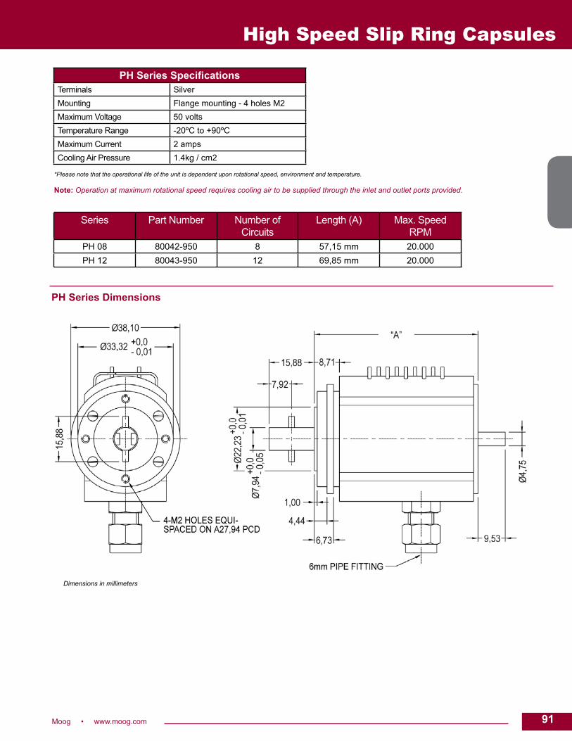
91Moog • www.moog.com 91
Dimensions in millimeters
High Speed Slip Ring Capsules
PH Series SpecificationsTerminals SilverMounting Flange mounting - 4 holes M2Maximum Voltage 50 voltsTemperature Range -20ºC to +90ºCMaximum Current 2 ampsCooling Air Pressure 1.4kg / cm2
Series Part Number Number of Circuits
Length (A) Max. Speed RPM
PH 08 80042-950 8 57,15 mm 20.000PH 12 80043-950 12 69,85 mm 20.000
PH Series Dimensions
*Please note that the operational life of the unit is dependent upon rotational speed, environment and temperature.
Note: Operation at maximum rotational speed requires cooling air to be supplied through the inlet and outlet ports provided.

92 Moog • www.moog.com
AC3757Miniature slip ring assembly
DescriptionA slip ring can be used in any electromechanical system that requires unrestrained, continuous rotation while transferring power and / or data from a stationary to a rotating structure. A slip ring is also called a rotary electrical interface, commutator, collector, swivel or a rotary joint.
The AC3757 high speed slip ring provides 36 circuits and operational speeds up to 6,000 rpm. Our fiber brush technology minimizes contact wear and resultant debris while it extends operational life.
Features• 36 circuits• High speed performance with customer’s cooling systems: - 4,000 rpm without cooling - 6,000 rpm with gas cooling (nitrogen)• Thermocoupled leads are available• Low noise. The low contact force of the fiber brush design
reduces resistance (noise) while providing superior power and data transfer capability.• Cooling tubes
Benefits• Fiber brush technology. The sliding electrical contacts used in the AC3757 slip ring features our fiber brush technology to provide these benefits: - Low contact force per fiber - Low contact wear rates - Contact surfaces that do not require lubrication - Ability to perform in vacuum and varied ambient conditions• Improved system performance. Slip rings can improve mechanical performance, simplify system operation and eliminate damage-prone wires dangling from movable joints.
Typical Applications
This slip ring provides high speed performance and is successfully serving in applications such as:
• Centrifuges• Tire testing• Gasoline or diesel engine testing
High Speed Slip Ring Capsules

93Moog • www.moog.com 93Dimensions in inches
Recommended Mounting Arrangement
Note: Other combinations of standard conductors and thermocouple leads are available.
High Speed Slip Ring Capsules
AC3757 SpecificationsRing O.D. 0.270 inchRing Pitch 0.032 inchFlange Diameter 1.600 inchBore NoneVolts (Peak to Peak) 70Circuits Leads1–26 30 (19 / 42) AWG silver plated standard copper conductor27–36 Solid chromel and alumel leadsAll leads are color coded extruded tefloninsulation.Chromel / alumel thermocouple pairs areattached to each bearing and to brushes#1 and #12 to monitor temperature.
Lead Wire Color CodesRing # Color Code Ring # Color Code Ring # Color Code Ring # Color Code
1 BLK 10 WHT 19 WHT-GRY 28 ORN (ALUMEL)
2 BRN 11 WHT-BLK 20 WHT-BLK-BRN 29 BLK (CHROMEL)
3 RED 12 WHT-BRN 21 WHT-BLK-RED 30 BRN (ALUMEL)
4 ORN 13 WHT-RED 22 WHT-BLK-ORN 31 RED (CHROMEL)
5 YEL 14 WHT-ORN 23 WHT-BLK-YEL 32 ORN (ALUMEL)
6 GRN 15 WHT-YEL 24 WHT-BLK-GRN 33 BLK (CHROMEL)
7 BLU 16 WHT-GRN 25 WHT-BLK-BLU 34 BRN (ALUMEL)
8 VIO 17 WHT-BLU 26 WHT-BLK-VIO 35 RED (CHROMEL)
9 GRY 18 WHT-VIO 27 RED (CHROMEL) 36 ORN (ALUMEL)
AC3757 Dimensions

94 Moog • www.moog.com
High Speed Slip Ring Capsules
AC6231 / AC6266High speed through-bore capsule
DescriptionA slip ring capsule can be used in any electromechanical system that requires unrestrained, intermittent, or continuous rotation while transferring power and / or data. A slip ring is also called a rotary electrical joint, collector, commutator, or swivel. A slip ring can improve system performance by simplifying operations and eliminating damage prone wires.
The AC6231 provides a high performance solution when a through- bore configuration with high-speed operation is required. This unit provides a 1-1/2 inch through-bore for shaft mounting and a compact 4.25 inch outside diameter and very short overall length for minimal space applications. The AC6231 provides eight 15 amp circuits and the AC6266 provides four 15 amp circuits. Similar in design to our very popular AC4598 and AC6200 series, this design features long life, fiber brush contact technology for ultimate performance in many challenging applications. Brush blocks are easily replaceable for extended life.
Features• 1-1/2 inch through-bore• Compact 4.25 inch outside diameter• Speeds up to 2500 rpm• Transfers power, as well as analog and digital signals• Rugged black anodized aluminum construction
Benefits• Compatible with data bus protocols• Fiber brush technology provides long life and operation• Compact packaging • Ease of installation
(outer cover removed for view)
Typical Applications
• Precision rotary equipment• High speed testing• Semiconductor handling systems• Industrial machinery• Robotics

95Moog • www.moog.com 95
High Speed Slip Ring Capsules
*Please note that the operational life of the unit is dependent upon rotational speed, environment and temperature.
SpecificationsOperating Speed 2500 rpm* continuousNumber of Circuits 8 (AC6231), 4 (AC6266)Lead Lengths 20 inch min.Lead Size / Type 14 AWGVoltage 220 VACOperating Temp. -40°C to +80°CCurrent Rating 15 amps / circuitNoise 60 milliohms max.
AC6231 / AC6266 Dimensions
Dimensions in inches
Part Number Length “L”AC6231 2.75 inches (69.85 mm)AC6266 1.97 inches (50.038 mm)

96 Moog • www.moog.com
EC3848High speed
DescriptionA slip ring can be used in any electromechanical system that requires unrestrained, continuous rotation while transmitting power and / or data from a stationary to a rotating structure. A slip ring is also called a rotary electrical interface, collector, swivel or rotary joint. A slip ring can improve system performance by simplifying operations and eliminating damage-prone wires dangling from moving joints.
The EC3848 features precious metal brushes and rings. Flying lead wires on the rotating side and solder terminals on the stator side complete the electrical connections. Precision ball bearings and the patented fiber brush design allow operation up to 10,000 rpm without the need for cooling equipment. Fiber brush technology offers several advantages over conventional slip ring contacts including multiple points of contact per brush bundle, low contact force per fiber and low contact wear rates. In addition, fiber brushes do not require lubrication and produce virtually no wear debris.
Features• Speeds up to 10,000 rpm without cooling• 2, 6, 8 and 10 circuit models• Precision ball bearings• 1 amp / 100 VDC circuits• Precious metal contacts
Benefits• Transfers control and data signals• Fiber brush technology provides maintenance-free operation (no lubrication required)• Standard design meets high speed requirements at a fraction of the cost of a custom assembly
Typical Applications
• Centrifuges• Various high speed instrumentation applications such as tire testing
High Speed Slip Ring Capsules

97Moog • www.moog.com 97
High Speed Slip Ring Capsules
* Please note that the operational life of the unit is dependent upon rotational speed, environment and temperature.
SpecificationsOperating Speed 0 - 10,000 rpm*Number of Rings Up to 10 (2, 6, 8 and 10)Electrical Connections 30 (19 / 42) AWG leads on rotor
Solder terminals on statorVoltage Low millivolt range to 100 VDCMaximum Ambient Temperature 50°C (120°F) over 1,000 rpm
80°C (175°F) up to 1,000 rpmContact Material Precious metalCurrent Rating 1.0 amps maximum per ringElectrical Noise 20 mΩ at 5 rpm
6 VDC, 50 mA currentCooling Not required
Lead Wire Color Code Ring # Color Ring # Color
1 BLK 6 GRN2 BRN 7 BLU3 RED 8 VIO4 ORN 9 GRY5 YEL 10 WHT
Dimensions in inches (millimeters) EC3848-10 outline shown (other models available upon request)
Part # Circuits Length “A”EC4294 2 0.60 inch (15,2 mm)
EC3848-6 6 0.91 inch (23,2 mm)EC4199 8 0.84 inch (21,3 mm)
EC3848-10 10 1.11 inch (28,3 mm)
REVISED 06/16

98 Moog • www.moog.com
PM SeriesDescriptionSuitable for a wide variety of industrial applications, the PM series is designed to transmit power and data signals at high speeds. Compatible with thermocouple and strain gauge instrumentation, the PM series is designed to maintain reliable performance under adverse operating conditions. Continuous silver connections ensure minimal thermal error. Quick and easy to install and available with 8, 12 and 24 circuits.
Features• Suitable for a wide variety of industrial applications• Transmits power and data signals at high speeds• Compatible with thermocouple and strain gauge instrumentation• Reliable performance under adverse operating conditions• Continuous silver connections ensure minimal thermal error• Quick and easy to install• Available with 8, 12 and 24 circuits
Benefits• High rotational speed• Low torque required to drive this unit
Typical Applications
• Instrumentation and testing
High Speed Slip Ring Capsules
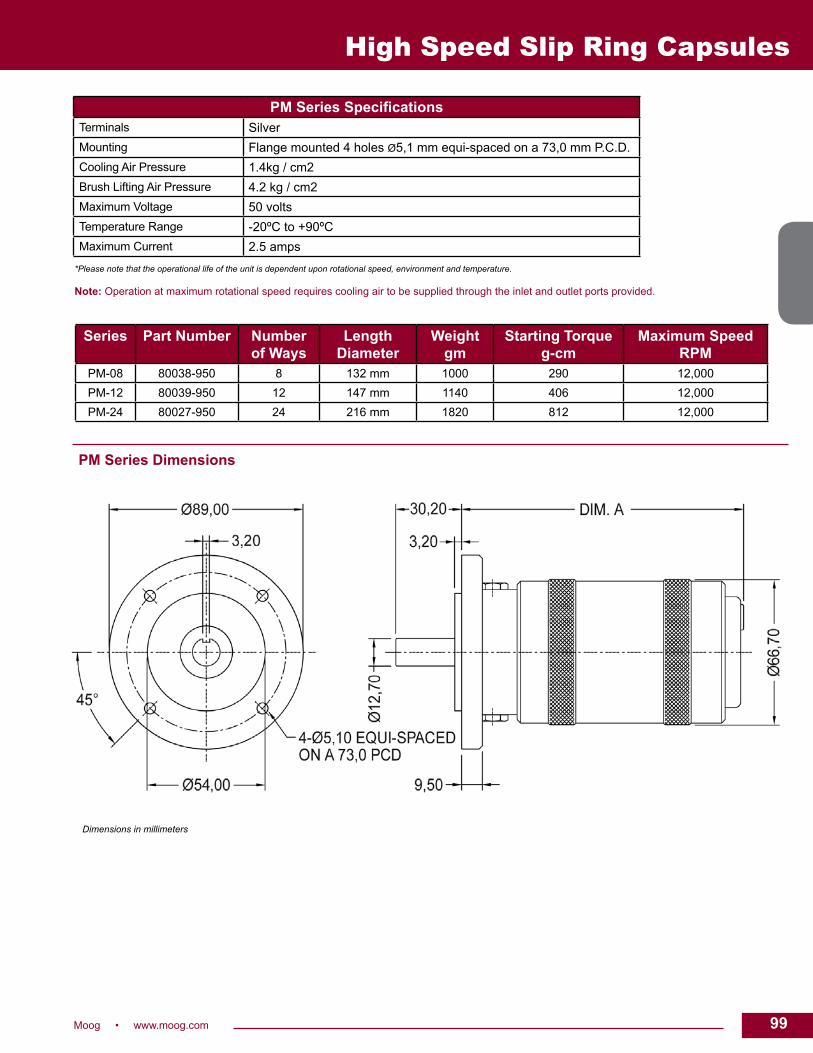
99Moog • www.moog.com 99
High Speed Slip Ring Capsules
Series Part Number Number of Ways
LengthDiameter
Weightgm
Starting Torque g-cm
Maximum Speed RPM
PM-08 80038-950 8 132 mm 1000 290 12,000PM-12 80039-950 12 147 mm 1140 406 12,000PM-24 80027-950 24 216 mm 1820 812 12,000
PM Series Dimensions
Dimensions in millimeters
PM Series SpecificationsTerminals SilverMounting Flange mounted 4 holes Ø5,1 mm equi-spaced on a 73,0 mm P.C.D.Cooling Air Pressure 1.4kg / cm2Brush Lifting Air Pressure 4.2 kg / cm2Maximum Voltage 50 voltsTemperature Range -20ºC to +90ºCMaximum Current 2.5 amps
*Please note that the operational life of the unit is dependent upon rotational speed, environment and temperature.
Note: Operation at maximum rotational speed requires cooling air to be supplied through the inlet and outlet ports provided.

100 Moog • www.moog.com
Large Diameter Slip Rings and High Speed Data Links
Non-Contacting Data Link (NCDL)DescriptionLarge bore non-contacting data link for high speed data communications with aggregate data rates exceeding 5 Gb/s.
Features• Integrate directly into slip ring or can stand alone• Bidirectional channel support• Requires less footprint than FORJ option• Modules packaged within footprint of slip ring
REVISED 08/17
Typical Applications • Medical CT scanners• Luggage scanners• Amusement rides• Cranes• Offshore mooring• Non-destructive test equipment• Industrial 3D imaging equipment
Large Diameter Slip RingDescriptionLarge bore slip rings represent the union of manufacturing processes and technologies that enable Moog to offer large, high volume slip rings with advanced features that are cost effective. The manufacturing processes allow the slip ring to be built in an assembly line fashion that significantly reduces delivery time and price.
Features• Platter or drum configuration • Diameters exceeding 70 inches (1.7 m)• Rotational speeds to 300 rpm • Power rings rated up to 1000 V • Power rings rated up to 300 amp • Quiet mechanical system operation • Low maintenance requirements• Multiple brush tip options with minimal debris • Capability of adding integral encoder, multiplexer, fiber optic rotary joint and non-contacting data link• Multiplexing: multiple bidirectional signals to minimize ring count• Encoder: capable of >15,000 counts
Fiber Optic Rotary Joint(FORJ)DescriptionLarge bore optical rotary joints for high speed optical communications with aggregate data rates exceeding 40 Gb/s. This patented technology also has the capability to transfer multiple data signals per optical channel.
Features• Integrated directly into slip ring or can stand alone• Inherent EMI immunity• Multiple electronics options (single channel, multi-channel, FPGA)• Significant system health diagnostics • Bidirectional channel support

101Moog • www.moog.com 101
Large Diameter Slip Rings and High Speed Data Links
Note: Slip ring designs within these general specifications may be for either military or commercial applications. Slip rings specifically designed for military applications may require licensing for export. Contact factory for export classification.
SpecificationsPart
NumberType ID* OD* High
Power Qty
Mid Power
Qty
Signal Qty
High Power Voltage
High Power Current (cont.)
Speed Integrated Encoder
Integrated Data Link
Data Link Options
CT6455 Drum 31.952 35.044 4 2 8 480 VAC 100 A 120 rpm No No
CT6764 Drum 37.400 39.984 4 2 0 480 VAC 100 A 120 rpm No No
CT7013 Platter 38.590 56.194 4 2 4 400 VAC 100 A 180 rpm No No
CT7311 Platter 39.622 54.818 4 2 4 380 VAC 100 A 180 rpm Yes NCDL - Single Ch 5 Gbps R->S
CT7093 Platter 42.520 54.100 3 2 4 500 VAC 100 A 180 rpm No FORJ - Single Ch 2.5 Gbps* R->S- 4 Ch 2.5 Gbps* R->S
CT7138 Platter 42.047 54.094 5 0 4 400 VAC 100 A 120 rpm No FORJ
CT6970 Platter 44.291 59.916 3 2 6 600 VAC 100 A 180 rpm Yes FORJ - Single Ch 2.5 Gbps* R->S- 4 Ch 2.5 Gbps* R->S- 4 Ch R->S with 1.25 Gbps* S->R path- Bidirectional Gigabit Ethernet (1000Base - SX)
CT6536 FORJ ONLY
39.624 43.040 300 rpm No
* OD, ID dimension does not include brush block, fiber optic hardware, or non-contacting data link mounting dimension
• All designs are RoHS compliant• Design to customer specifications
Dimensions in inches [milimeters]
CT7311 Dimensions
REVISED 08/17

102 Moog • www.moog.com
Large Diameter Slip Rings and High Speed Data Links
CT6970 Dimensions
Dimensions in millimeters [inches]
REVISED 08/17
Dimensions in inches [milimeters]
CT7138 Dimensions

103Moog • www.moog.com 103
Large Diameter Slip Rings and High Speed Data Links
CT6536 Dimensions
Dimensions in inches [millimeters]
Dimensions in inches
CT6455 Dimensions
REVISED 08/17

104 Moog • www.moog.com
Separates
AC2690 – Slip RingAC259 – Brush BlockMiniature slip ring separate assemblies DescriptionSometimes a self-contained “capsule” slip ring is not practical due to system size constraints or cost limitations. We can provide the slip ring (rotor) and brush block (stator) as separate components to be mated by the customer in their system. The rotor is supplied in a drum configuration which features consecutive individual rings along the axis of rotation. Miniature separates may have slip ring rotor diameters less than 0.100 inch.
A slip ring can be used in any electromechanical system that requires unrestrained, intermittent or continuous rotation while transmitting power and / or data. It can improve mechanical performance, simplify system operation and eliminate damage-prone wires dangling from movable joints.
Options AvailableSlip Ring• Raised barrier (.110 diameter)• V-groove (90°) in each ring
Brush Block• Flying leads• Gold or tin plated terminals
Typical Applications
• Instrumentation• Displays and avionics• Testing and measuring• Custom machinery• OEM machinery

105Moog • www.moog.com 105
Separates
Materials: • Contact surface - gold• Backshaft - 303 stainless steel • Leads - #30 AWG silver plated copper,
Teflon® insulated• Dielectric - plastic (mineral filled epoxy)• Current rating - 1 amp / ckts
Slip Ring Separate: AC2690 Specifications
Materials: • Brushes - precious metal• Plastic - polyester• Terminals - .015 thick brass, tin (gold optional) plated• Flying leads optional• Current rating - 1 amp / ckts
Brush Block Separate: AC259 Specifications
Dimensions in inches (millimeters)
Teflon® is a registered trademark of E.I. du Pont de Nemours and Co.
Note: For optimal life and performance, ring and brush contact areas should be lubed.
Part # # of Circuits Dimension “C”
AC2690–1 1 0.100 inches (2,54 mm)
AC2690–2 2 0.150 (3,81)
AC2690–3 3 0.200 (5,08)
AC2690–4 4 0.250 (6,35)
AC2690–5 5 0.300 (7,62)
AC2690–6 6 0.350 (8,89)
AC2690–7 7 0.400 (10,16)
AC2690–8 8 0.450 (11,43)
AC2690–9 9 0.500 (12,7)
AC2690–10 10 0.550 (13,97)
Lead Wire Color Codes
#1 Brown
#2 Red
#3 Orange
#4 Yellow
#5 Green
#6 Blue
#7 Violet
#8 Gray
#9 White
#10 Black
Part # # of Circuits Dimension “A” Dimension “B”
AC259–1 1 0.100 inches (2,54 mm) 0.100 inches (2,54 mm)
AC259–2 2 0.140 (3,56) 0.140 (3,56)
AC259–3 3 0.190 (4,83) 0.156 (3,96)
AC259–4 4 0.240 (6,10) 0.156 (3,96)
AC259–5 5 0.290 (7,37) 0.156 (3,96)
AC259–6 6 0.340 (8,64) 0.156 (3,96)
AC259–7 7 0.390 (9,91) 0.156 (3,96)
AC259–8 8 0.440 (11,18) 0.156 (3,96)
AC259–9 9 0.490 (12,45) 0.156 (3,96)
AC259–10 10 0.540 (13,72) 0.156 (3,96)

106 Moog • www.moog.com
Separates
MD6038 – Slip RingMD6043 – Brush BlockMiniature slip ring separates with through-bore
DescriptionA slip ring can be used in any electromechanical system that requires unrestrained, continuous rotation while transferring power and / or data from a stationary to a rotating structure. A slip ring is also called a rotary electrical interface, commutator, collector, swivel or a rotary joint.
Sometimes a self contained “capsule” is not practical due to size constraints or cost limitations, and a “separate” is the solution. The term separate indicates an individual rotor / brush block combination. If a separate rotor / stator approach is best for your application, consider our MD series.
The MD series slip ring separate has 6 circuits and features a 3/8” unobstructed bore through the center that provides routing space for hydraulics, pneumatics, or for a concentric shaft mount.
Features• 6 circuits• 3/8 inch unobstructed bore. Other bore sizes also available.• Gold-on-gold contacts. Provide enhanced conductivity
and low noise.• Excellent signal handling performance. Noise as low as
15 milliohms per circuit pair can be achieved at 60-100 rpm.
Benefits• Improved system performance. Slip rings can improve mechanical
performance, simplify system operation and eliminate damage-prone wires dangling from movable joints.
• Long Life. We use gold on gold contacts to extend unit life to exceed or meet the requirements for most commercial / industrial requirements.
Typical Applications
This separate assembly provides high speed performance and an unobstructed bore-through the center of the unit. It is successfully performing in instrumentation applications where miniaturization is critical, such as:
• Aircraft cockpit instruments• Sputtering machines for the
manufacture of integrated circuits• Custom machinery• OEM machinery• Power tools

107Moog • www.moog.com 107
Separates
Note: For optimal life and performance, ring and brush contact areas should be lubed.
SpecificationsRing O.D. .550 inch (13,9 mm)Ring-to-Ring Pitch .060 inch (1,52 mm)Bore .376 inch (9,55 mm)Volts 240 VDCCurrent Rating 2 amps / cktRing Groove Geometry:V-Groove with Raised Barriers
Lead Wire Color CodesRing # Color Code
1 BLK
2 BRN3 RED4 ORN5 YEL6 GRN
Dimensions in inches (millimeters)
MD6038 Dimensions
MD6043 Dimensions

108 Moog • www.moog.com
Platter Separates
Slip Ring Platter Separates DescriptionFor space requirements, platter separates can be an ideal solution. The units supplied generally consist of a slip ring based on a PCB style and a matching brush block or board depending on the requirements. Various configurations are manufactured – from simple components, through units with fixed spacing arrangements to products with integrated bearing components.
Full mounting details are supplied with the unit and the customer is required to lubricate the slip ring during installation.
Features• Separate components or integrated assemblies• Simple installation• Pre-set brush springs
Benefits• Suits applications with minimal available space• Can utilize existing bearing system• Custom configuration to suit application
Typical Applications
• Process machinery• Medical equipment• Test and measurement equipment

109Moog • www.moog.com 109
Fiber Optic Rotary Joints (FORJ)
Fiber Optic Rotary JointsDescriptionFiber Optic Rotary Joints (FORJs) are to optical signals what electrical slip rings are to electrical signals, a means to pass signals across rotating interfaces, particularly when transmitting large amounts of data. FORJs maintain the intrinsic advantages of fiber end to end. Moog has been producing fiber optic rotary joints for over 20 years.
Single or Multi-channel FORJs are available in single and multi-channel options. The most cost and size efficient options are the single and dual channel designs. If more than two fibers are present in a system, multiplexing solutions are available to combine multiple channels onto one or two fibers to allow the use of a one or two channel FORJ.
In cases where more than two fibers are required, Moog has three designs; FO190, FO242 and FO291 where single channels are stacked to achieve the desired number of channels. The FO300 uses a common de-rotating optical element for all fiber channels.
Singlemode or Multimode Singlemode fibers allow the propagation of a singlemode of optical energy due to their small core size and small numerical aperture and for this reason they exhibit very high bandwidths. Most singlemode fiber systems operate at 1300 nm and 1550 nm wavelengths because of lower fiber attenuation at these wavelengths. Because of these smaller core sizes and numerical aperture, singlemode FORJs must be designed with very precise mechanical alignments.
Multimode fibers have large cores and large numerical apertures allowing the propagation of multiple modes of optical energy. These features allow larger amounts of light to be transmitted from sources such as LEDs and VCSELs, but result in higher attenuation and dispersion. Because of these attenuation and dispersion features, multimode fiber systems are typically used for shorter datacom links. Most multimode systems operate at 850 nm and 1300 nm. Features • Ruggedized for harsh environments • Compact sizes • Variety of configuration options • Custom designs available
Typical Applications
• Robotics• Vehicle turrets• Radar antennas• Medical systems• Security systems• Sensor platforms• Material handling systems• Remotely operated vehicles• Fiber optic cable reels• Video surveillance systems• Marine propulsion systems• Wind energy turbines

110 Moog • www.moog.com
Fiber Optic Rotary Joints (FORJ)
FORJ Performance Data
Shock and VibrationMoog Component Group FORJs support high shock and vibration environments, long life requirements of more than 200,000 hours and long data links over 100 km of fiber. Units are available that are tested to MIL-STD-167-1, MIL-STD-202, MIL-STD-204 for vibration and MIL-STD-810D / E and MIL-STD-901D for shock.
Options• Supply and installation of customer specific connectors and fibers• Customization of mounting configurations, housing
materials and drive couplers• Fluid filling and pressure compensation for underwater use
* The FO242 and FO190 can be combined to offer a hybrid multimode and singlemode solution * Right angle options available SM = Singlemode MM = Multimode ** Consult factory for number of passes available for SM and MM combination applications** More passes are available with a custom design *** Pigtail length effect with plastic fiber *** 1 MM pass can be accommodated on the FO291
Note: Optical values for all listed multimode FORJs are based on use with LED sources.
Product Performance Physical
Fiber Type Channels Insertion Loss - Maximum dB MM = 5.5 dB
Maximum Rotational
Speed
Operating Temperature
Size Inches (mm)
Standard Interface
- SM MM - SM MM RPM - Minimum Length
Flange Diameter
Drum Diameter
Pigtail / Adaptor
Connector Type
Pigtail Length
FO228 N Y 1 NA 4.0 100 -40 to +75°C 1.75 (44.45) 1.50 (38.10) 0.73 (18.54) Adaptor FC or ST NA
FO197 N Y 1 NA 3 1000 -40 to +60°C 2.38 (60.45) 1.50 (38.10) 0.62 (15.74) Pigtail or Adaptor
FC, ST for Adaptors; As Required on Pigtails
As Required
FO206 Y Y 1 3.5 NA 1000 -40 to +60°C 2.36 (59.94) 1.50 (38.10) 0.77 (19.55) Pigtail or Adaptor
FC / PC Standard Alternates Available
As Required
FO285 *
Y Y 1 3.5 NA 500 + -55 to +75°C 1.02 (25.90) 0.75 (19.05) 0.037 (.93) Pigtail As Required As Required
FO286 *
N Y 1 NA 2.5 500 + -55 to +75°C 0.75 (19.05) 0.75 (19.05) 0.037 (.93) Pigtail As Required As Required
FO310 Y Y 1 1.5 1.5 100 -40 to +85°C 3.41 (86.6) 1.5 (38.1) 0.63 (15.9) Pigtail As Required As Required
FO300A **
Y Y 2 to 17 < 4.0 dB < 4.0 dB 100 -40 to +60°C 4.22 (107.18) 1.8 (45.72) 2.35 (59.69) Pigtail As Required As Required
FO300B **
Y Y 2 to 31 < 4.5 dB < 5.0 dB 100 -40 to +60°C 5.76 (146.2) 2.1 (53.34) 2.72 (69.1) Pigtail As Required As Required
FO300C **
Y N 2 to 52 < 5.0 dB NA 100 -40 to +60°C 6.79 (172.5) 3.1 (78.74) 3.72 (94.5) Pigtail As Required As Required
FO215 *
N Y 2 NA 5.5 500 + -40 to +60°C P: 3.30 (83.82) P: 1.50 (38.10)
P: 0.75 (19.05)
Pigtail or Adaptor
ST, FC, SC, LC
As Required
FO257 Plastic 2 8 ***
500 + -40 to +60°C 3.47 (88.13) 1.85 (46.99) 1.24 (31.49) Pigtail ST or SMA As Required
FO292 *
N Y 2 NA 5.5 500 + -40 to +60°C 2.25 (57.15) 1.25 (31.75) 0.50 (12.7) Pigtail ST, FC, SC, LC
As Required
FO242 *
Y N 2 to 5 5.5 NA 100 + -40 to +60°C See Data Sheet
5.02 (127.50) 5.00 (127.00)
Adaptor FC / PC Standard;
ST Optional
NA
FO291 ***
Y Y 2 to 9 6 5.5 100 + -40 to +60°C See Data Sheet
See Data Sheet
See Data Sheet
Adaptor FC / PC Standard;
ST Optional
NA
FO190 *
N Y 2 to 21** NA 5.5 100 -40 to +60°C See Data Sheet
5.02 (127.50) 5.00 (127.0) Adaptor FC / PC, ST NA
Hybrid Units
H18 Y Y 1 Optic 18 Elec.
3.5 2.5 500 -20 to +60°C 3.4 (86.36) MM, 3.64 (92.45) SM
1.75 (44.45) 0.87 (22.0) Pigtail As Required As Required
H24 Y Y 1 Optic 24 Elec.
3.5 2.5 500 -20 to +60°C 3.7 (93.98) MM, 3.94 (100.07) SM
1.75 (44.45) 0.87 (22.0) Pigtail As Required As Required

111Moog • www.moog.com 111
* The FO242 and FO190 can be combined to offer a hybrid multimode and singlemode solution * Right angle options available SM = Singlemode MM = Multimode ** Consult factory for number of passes available for SM and MM combination applications** More passes are available with a custom design *** Pigtail length effect with plastic fiber *** 1 MM pass can be accommodated on the FO291
Note: Optical values for all listed multimode FORJs are based on use with LED sources.
Fiber Optic Rotary Joints (FORJ)
FO228 Fiber optic rotary joint DescriptionThe FO228, a single-pass multimode fiber optic rotary joint (FORJ), is passive and bidirectional, and maintain the benefits of fiber optics (such as high bandwidth and EMI immunity) in systems with a rotational interface.
This cost efficient FORJ model is designed for applications having moderate demands for optical performance and life. Due to its lens-less design, it can operate at any wavelength supported by the fiber used in the assembly.
The FORJ can be combined with our electrical and fluid slip rings, giving a single, compact package for optical signals, electrical power and fluid transfer.
Features• Provides rotary coupling for a multimode fiber link • Passive bidirectional device • Low cost • Can be combined with our electrical slips and fluid unions • Alternative drive coupling and mounting arrangements are available (consult factory for specification details) • Connectorized interfaces, for easy fiber cable replacement • Can be integrated into existing slip ring designs • Aluminum or anodized aluminum housing • Rugged design - MIL-STD-167-1 ship vibration - MIL-STD-810D functional shock (40 g)
Typical Applications
• Cable reelers used in EOD robots • Material handling systems • Security cameras

112 Moog • www.moog.com
Fiber Optic Rotary Joints (FORJ)
FO228 Dimensions
Hybrid UnitsCan be combined with electrical and fluid slip rings
Mounting OptionsAvailable with or without mounting flange (consult factory for details)
TerminationsBuilt-in FC or ST connector receptacles
FO228 SpecificationsFiber Size (Microns) 50/125 or 62.5/125 (consult factory for other sizes)Insertion Loss Typical < 2.5 dB Maximum < 4.0 dBRotation Variation Typical < 0.5 dB Maximum < 1.0 dBWavelength Broadband (fiber dependant)Rotational Speeds To 100 rpm. Higher rotational speeds should be discussed with the factoryTemperature -40 to +75 deg C. Consult factory for extended rangeLife 500,000 revolutionsExterior Surfaces Aluminum or anodized aluminumVibration Tested to MIL-STD-167-1 (ships)Shock Tested to MIL-STD-810DTerminations Standard with ST or FC connector receptacles. Can be pigtailed with cable and connectors to
meet customer’s requirements.Pigtail Length As required
Dimensions in inches [millimeters]
Shaft Mounting Arrangement Body Mounting Arrangement

113Moog • www.moog.com 113
FO197 Fiber optic rotary joint
DescriptionThe FO197 is a single-pass, multimode fiber optic rotary joint (FORJ). It is passive and bidirectional, and allows the transfer of any type of optical signal across rotational interfaces.
The FO197 fiber optic rotary joint can be combined with our electrical and / or fluid slip rings, providing a single, compact package for optical signals, electrical power and fluid transfer.
The FORJ can be assembled with pigtail lengths tailored to the customer’s application or installed with connector bushings (ST or FC). Housing, mounting flange and drive features can also be customized to meet the customer’s requirements.
Features• Provides rotary coupling for a multimode fiber link• Passive bidirectional device• Can be combined with our electrical slips and fluid unions • Alternative drive coupling and mounting arrangements are available (consult factory for specification details)• Connectorized interfaces, for easy fiber cable replacement• Can be integrated into existing slip ring designs• Stainless steel, aluminum or anodized aluminum housing• Rugged design - MIL-STD-167-1 ship vibration - MIL-STD-810D functional shock (40 g)
Typical Applications
• Remote I/O in industrial machinery• Video surveillance systems• Material handling systems• Sensor platforms• Indexing tables• Cable reels• Robotics• Turrets
Fiber Optic Rotary Joints (FORJ)

114 Moog • www.moog.com
FO197 Dimensions
Hybrid UnitsCan be combined with electrical and fluid slip rings.
MountingSee diagrams for details. Customized mounting flanges also available.
PressureOptional fuid-filled version for pressure compensation (in a slightly lager housing than shown).
Exterior SurfacesStainless steel, aluminum or anodized.
TerminationsST or FC connector receptacles or pigtailed with cable and connectors to meet customer’s requirements.
FO197 SpecificationsFiber Size (Microns) 50 / 125, 62.5 / 125, 100 / 140 or 200 / 230Insertion Loss Typical < 1.5 dB Maximum < 3.0 dBRotation Variation Typical < 0.5 dB Maximum < 1.0 dBBack Reflection Typical 22 dB 18 dB MinimumWavelengths 850, 1300 or 1550 nm. Consult factory for multi-wavelength applications.Rotational Speeds To 1000 rpm. Higher rotational speeds should be discussed with the factory.Temperature -40 to +60 deg C (dry version). Consult factory for extended range.Dispersion < 10 picoseconds (calculated)Exterior Surfaces Stainless steel, aluminum or anodized aluminumVibration Tested to MIL-STD-167-1 (ships)Shock Tested to MIL-STD-810DTerminations ST or FC connector receptacles or pigtailed with cable and connectors to meet
customer’s requirementsPressure Up to 10000 psi (69,000 kPa) for fluid filled version*Pigtail Length As required
*Fluid filled version is slightly larger than shown below.
Fiber Optic Rotary Joints (FORJ)
Shaft Mounting Arrangement (S)Body Mounting Arrangement (B)

115Moog • www.moog.com 115
FO206 Fiber optic rotary joint
DescriptionThe FO206 is a single-pass, singlemode fiber optic rotary joint (FORJ). It is passive and bidirectional, and allows the transfer of optical signals across rotational interfaces.
The FORJ maintains the full benefit of fiber optics end-to-end in digital and analog transmission to and from rotating equipment. These benefits include high bandwidth and immunity to most forms of EMI.
The FO206 can be combined with our electrical and fluid slip rings, providing a single, compact package for optical signals, electrical power and fluid transfer. Most of the external features on the FO206 can be modified to meet the customer’s custom requirements.
Features• Provides rotary coupling for a singlemode fiber link • Passive bidirectional device • Can be combined with our electrical slips and fluid unions • Connectorized interfaces, for easy fiber cable replacement • Customized mounting flanges available • Optional fluid-filled version for deep submergence to 10,000 psi (69,000 kPa) • Can be integrated into existing slip ring designs • Stainless steel housing • Rugged design - MIL-STD-167-1 ship vibration - MIL-STD-810D functional shock (40 g)
Typical Applications
• Vehicle turrets• Industrial machine tools• Undersea telemetry• Radar antennas• Cable reels• Robotics
Fiber Optic Rotary Joints (FORJ)

116 Moog • www.moog.com
Fiber Optic Rotary Joints (FORJ)
Dimensions in millimeters [inches]
FO206 SpecificationsFiber Size (Microns) 9 / 125 SMF-28. Consult factory for other SM fiber typesInsertion Loss Typical < 1.5 dB Maximum < 3.5 dBRotation Variation Typical < 0.5 dB Maximum < 1.0 dB
Standard Typical 22 dB 20 dB MinimumOptional Typical 40 dB 35 dB Minimum
Wavelengths 1310 / 1550 nm. Consult factory for other wavelengths such as CWDM (18 wavelengths from 1271 nm to 1611 nm in 20 nm increments).
Rotational Speeds To 1000 rpm. Higher rotational speeds should be discussed with the factory.Temperature -40 to +60 deg C (dry version)
-20 to +60 deg C (wet version). Consult factory for extended range.Dispersion < 50 fs / nm (calculated)Exterior Surfaces Stainless steelVibration Tested to MIL-STD-167-1 (ships)Shock Tested to MIL-STD-810DTerminations Standard is with FC / PC connector receptacles at each end. Alternative
connectors types available dependant on configuration (ST, FC / APC). Pigtails can be supplied with cable and connectors to meet customer’s requirements.
Pressure Up to 10000 psi (69,000 kPa) for fluid filled version*Pigtail Length As required
Back Reflection
*Fluid filled version is slightly larger than shown below.
FO206 Dimensions
REVISED 05/15

117Moog • www.moog.com 117
FO285 / FO286 Fiber optic rotary joint
DescriptionThe FO285 (single-pass singlemode) and the FO286 (single-pass multimode) are passive and bidirectional, and allow the transfer of optical signals across rotational interfaces.
With a body diameter of only 9.5 mm and lengths of 26 mm and 19 mm for the FO285 and FO286 respectively, both units are ideally suited to applications where size and weight are critical issues. An extremely cost effective solution for high data rate signals, both models also offer other benefits of fiber optics, including low spark hazard and immunity to electromagnetic interference.
Both models can be combined with our electrical and fluid slip rings, and with our entire line of video and data multiplexers to provide a complete solution.
Features• Provides rotary coupling for a multimode or singlemode fiber link • Passive bidirectional device • Low cost, small size • Can be combined with our electrical slips and fluid unions • Alternative drive coupling and mounting arrangements are available (consult factory for specification details) • Can be integrated into existing slip ring designs • Stainless steel or aluminum construction • Rugged design - MIL-STD-167-1 ship vibration - MIL-STD-810F functional shock (40 g)• 90° fiber exits available for limited space requirements
Typical Applications
• Unmanned ground vehicles• Robots• Surveillance systems• Industrial automation• Unmanned aerial vehicles and sub-systems
Fiber Optic Rotary Joints (FORJ)

118 Moog • www.moog.com
FO285 and FO286 Dimensions
SpecificationsFO285 (Singlemode) FO286 (Multimode)
Fiber Size (Microns) 9 / 125 SMF-28 (consult factory for other sizes)
50 / 125 or 62.5 / 125 (consult factory for other sizes)
Insertion Loss Typical < 1.5 dB Maximum < 3.5 dB Typical < 1.5 dB Maximum < 2.5 dBRotation Variation Typical < 0.5 dB Maximum < 1.5 dB Typical < 0.5 dB Maximum < 1.0 dBBack Reflection* Typical 22 dB 18 dB Minimum Typical 22 dB 18 dB MinimumWavelength 1310 / 1550 nm. Consult factory for other
wavelengths such as CWDM (18 wavelengths from 1271 nm to 1611 nm in 20 nm increments).
850, 1300 or 1550 nm (consult factory for multi-wavelengths applications)
Dimensions 9.5 mm diameter x 26 mm length 9.5 mm diameter x 19 mm lengthWeight/Material Stainless steel: 16 g
(pigtailed with connectors)Aluminum: 7g, Stainless steel: 14 g (pigtailed with connectors)
Rotational Speeds To 1000 rpm. Higher rotational speeds should be discussed with the factory.Temperature -55 to +75 deg C. Consult factory for extended range.Vibration Tested to MIL-STD-167-1 (ships)Shock Tested to MIL-STD-810FTerminations Pigtailed with cable and connectors to meet customer’s requirements
900 micron buffered cable standardPigtail Length As required
*35 dB minimum back reflection option available for FO285.
Dimensions in millimeters [inches]
Fiber Optic Rotary Joints (FORJ)
MODEL 285 SM “L” = 17 [.68]MODEL 286 MM “L” = 11 [.43]
REVISED 10/15

119Moog • www.moog.com 119
Fiber Optic Rotary Joints (FORJ)
Typical Applications • Winches and cable reels for optical sensor systems - Distributed Temperature Sensing (DTS) - Temperature Point Sensor Arrays (TPSA) using Fiber Bragg Gratings (FBG)• Distributed Acoustic Sensing (DAS)• Pitch control data and / or fiber-optic blade sensing for wind turbines• Sensor systems for helicopter rotor blades• Optical Coherence Tomography (OCT)
FO310 Sealed high performance fiber optic rotary joint
DescriptionThe FO310 is a sealed single-pass fiber optic rotary joint (FORJ) which is factory configured to transfer optical signals over either singlemode or multimode fiber. The FO310 supports both analog and digital optical signals, and is especially suited for sensitive single-pass optical sensing applications where optical insertion loss and back reflection must be minimized.
The FO310 FORJ has a stainless steel housing and is environmentally sealed to an ingress protection rating of IP67. It can be combined with Moog electrical and / or fluid slip rings, providing a single, complete package for optical signals, electrical power, and fluid transfer over a rotating interface.
This FORJ is assembled with either bulkhead connectors or fiber pigtails and connectors to suit the application. Housing, mounting flange, and drive features can be customized to meet specific customer requirements.
Features• Passive bidirectional optical transmission• Low optical insertion loss for common sensor wavelengths• High return loss (i.e. low back reflection) available• Provides rotary coupling for either a singlemode or multimode fiber link with the same footprint• Can be combined with Moog electrical slip rings and fluid unions• Can be integrated into existing slip ring designs• Rugged design with IP 67 rating, MIL-STD-167-1 Ships vibration and MIL-STD-810 functional shock (40g)• Bulkhead connector and Pigtailed versions available
Benefits• Low back reflection and insertion losses allow for FORJ integration with very sensitive optical sensor measurement systems• Environmentally sealed design allows for long-life in rugged installations and reduces maintenance costs• Supports either singlemode or multimode fiber, allowing future upgrade without modifying the surrounding mechanical infrastructure

120 Moog • www.moog.com
Fiber Optic Rotary Joints (FORJ)
FO310 SpecificationsSinglemode Multimode
Fiber Size 9 / 125 Single Mode 50 / 125 or 62.5 / 125 MultimodeInsertion Loss Maximum 1.5 dB (Typical 1.0 dB) Maximum 1.5 dB (Typical 1.0 dB)Rotation Variation Maximum 1.0 dB (Typical 0.5 dB) Maximum 1.0 dB (Typical 0.5 dB)Back Reflection Minimum 55 dB Minimum 30 dB (Typical 32 dB)Wavelength Options Optimized for:
• 1310 / 1550 nm WDM and CWDM communication bands, and;• 900-1100 nm sensor band (point-source tested at 1060 nm)
Optimized for:• 850 / 1300 nm WDM communication bands, and; • 900-1100 nm sensor band (point-source tested at 1060 nm)
Rotational Speeds 100 rpm. For other requirements contact factory. 100 rpm. For other requirements contact factory.Temperature -40°C to +85°C -40°C to +85°CExterior Surfaces Stainless Steel Stainless SteelIngress Protection IP67 IP67Vibration Tested to MIL-STD-167-1 (Ships) Tested to MIL-STD-167-1 (Ships)Shock Tested to MIL-STD-810D Tested to MIL-STD-810DTerminations Bulkhead or Pigtailed with ST, FC / PC, or FC / APC
connectors to meet customer requirements. FC /APC required to achieve extended back reflection specification
Bulkhead or Pigtailed with ST, FC / PC, or FC / APC connectors to meet customer requirements. FC /APC required to achieve extended back reflection specification.
Pigtail Length As required As required
FO310 Dimensions
Dimensions in inches [mm]

121Moog • www.moog.com 121
FO300 Fiber optic rotary joint
DescriptionThe FO300 is a multi-pass fiber optic rotary joint (FORJ). It allows the transfer of optical signals across a rotational interface and is passive and bidirectional. The smaller version “A” accommodates up to 17 separate singlemode or multimode optical fibers. Version “B” supports up to 31 separate channels. The largest version “C” supports up to 52 separate channels. Pressure compensation is available for use in subsea applications, with slightly increased length and diameter.
The FO300 can be combined with electrical and / or fluid slip rings, providing a single package for optical signals, electrical power and fluid transfer.
Features• Up to 52 fiber optic channels in a very small form factor• The smaller version “A” accommodates up to 17 separate singlemode or multimode optical fibers, version “B” accommodates up to 31 separate channels and the largest version “C” supports up to 52 separate channels • Can be combined with electrical slip rings and fluid rotary unions • Stainless steel construction • Rugged design
Fiber Optic Rotary Joints (FORJ)
Typical Applications
• Vehicle Turrets• Radar Antennas• Material Handling• Remotely Operated Vehicles• Fiber Optic Cable Reels• Floating Production, Storage,
Offloading (FPSO) Turrets

122 Moog • www.moog.com
FO300 SpecificationsFiber Type 9 / 125 Singlemode 50 / 125 or 62.5 / 125 Multimode
Wavelength1310 nm or 1550 nm,
or single CWDM wavelength
1310 nm and 1550 nm, or multiple CWDM
wavelength850 nm and 1300 nm
Version “A” (< 17 Channels)Maximum Insertion Loss Over Rotation < 4.0 dB < 4.0 dB
Insertion Loss Variation Over Rotation < 1.5 dB < 2.5 dB < 1.5 dB
Version “B” (< 31 Channels)
Maximum Insertion Loss Over Rotation < 4.5 dB < 5.0 dB
Insertion Loss Variation Over Rotation < 1.5 dB < 2.5 dB < 1.5 dBVersion “C” (< 52 Channels)
Maximum Insertion Loss Over Rotation < 5.0 dB NAInsertion Loss Variation Over Rotation < 2.0 dB < 3.0 dB NA
All VersionsMinimum Return Loss Over Rotation 18 dB, consult factory for higher return lossRotation Speed To 100 rpm, consult factory for extended rangeTemperature -40° C to +60° C, consult factory for extended rangeExterior Surfaces Stainless steel
Vibration Tested to MIL-STD-167-1 (ships) / MIL-STD-810G 514.6
Shock Tested to MIL-STD-810G 514.6Connectors As requestedPigtail Length As requested
Fiber Optic Rotary Joints (FORJ)
• Consult factory for higher channel count • Consult factory for different fiber types • Pigtailed FORJ; measured from outside ends of FORJ flanges, does not include shaft torque pins, strain relief, or pigtails • Mounting holes for Version “C” are 8X #10-24 UNC-2B, .31 [7.9] minimum thread depth
Dimensions in inches [millimeters]
Dimensions Inches [mm]
Version “A” Version “B” Version “C”
DIM “1” Ø2.35 [59.7] Ø2.72 [69.1] Ø3.72 [94.5]DIM “2” 4.22 [107.2] 5.76 [146.2] 6.79 [172.5]DIM “3” Ø1.800 [45.72] Ø2.100 [53.34] Ø3.100 [78.74]DIM “4” Ø.90 [22.9] Ø1.06 [26.92] Ø1.56 [39.6]DIM “5” Ø1.30 [33] Ø1.55 [39.4] Ø2.05 [52.1]DIM “6” .31 [8.1] .32 [8.1] .32 [8.1]DIM “7” Ø.90 [22.9] Ø1.24 [31.5] Ø1.48 [37.6]DIM “8” .38 [9.6] .38 [9.6] .38 [9.6]DIM “9” Ø1.650 [41.91] Ø1.800 [45.72] Ø2.720 [69.09]
FO300 Dimensions
REVISED 05/15

123Moog • www.moog.com 123
FO215 Fiber optic rotary joint
DescriptionThe FO215 is an ultra-compact, two pass, multimode fiber optic rotary joint (FORJ). It is passive and bidirectional, and allows the transfer of optical signals on two separate optical fibers across rotational interfaces.
The FO215 can be combined with our electrical and fluid slip rings, giving a single, compact package for optical signals, electrical power and fluid transfer.
The FORJ can be assembled with pigtail lengths tailored to the customer’s application. Housing, mounting flange and drive features can also be customized to meet the customer’s requirements.
Features• Provides rotary coupling for two multimode fibers• Passive bidirectional device• Can be combined with our electrical slips and fluid unions • Connectorized version allows for easy fiber cable replacement• Customized mounting flanges available• Optional fluid-filled version for deep submergence to 10,000 psi
(69,000 kPa)• Can be integrated into existing slip ring designs• Stainless steel housing (aluminum for connectorized version)• Rugged design - MIL-STD-167-1 ship vibration - MIL-STD-810E functional shock (40 g) Typical Applications
• Winches and cable reels for remotely operated vehicles• Remote I / O in industrial machinery• Video surveillance systems• Material handling systems• Sensor platforms• Robots• Turrets
Fiber Optic Rotary Joints (FORJ)

124 Moog • www.moog.com
FO215 SpecificationsFiber Size (Microns): 50 / 125 or 62.5 / 125. Consult factory for other fiber types.
Insertion Loss*Typical Maximum
Channel 1 < 1.5 dB < 3.0 dBChannel 2 < 4.5 dB < 5.5 dB
Rotation Variation Typical < 0.5 dB Maximum < 1.0 dBBack Reflection Consult factoryWavelengths 850, 1300 or 1550 nm. Consult factory for other multi-wavelength applications.Rotational Speeds To 500 rpm. Higher rotational speeds should be discussed with the factory.Temperature -40 to +60 deg C (dry version)
-20 to +60 deg C (wet version) Consult factory for extended range.Dispersion < 10 ps (calculated)Exterior Surfaces Stainless steel (aluminum for connectorized version)Vibration Tested to MIL-STD-167-1 (ships)Shock Tested to MIL-STD-810ETerminations Standard is with pigtail cables terminated with ST connectors at each end. Alternative connectors
types available (FC, SC, LC).Pressure Up to 10000 psi (69,000 kPa) for fluid filled version**Pigtail Length As required
*Add 0.5 - 1.0 dB to the insertion loss for connectorized version **Fluid filled version is slightly larger than shown below. Note: Optical values given are based on use with LED sources.
Fiber Optic Rotary Joints (FORJ)
FO215 Dimensions
Dimensions in inches [millimeters]

125Moog • www.moog.com 125
Fiber Optic Rotary Joints (FORJ)
FO257 Fiber optic rotary joint
DescriptionThe FO257 is a compact, two pass, fiber optic rotary joint (FORJ) for plastic optical fiber.
Ideally suited to SERCOS applications, the FO257 can be combined with our electrical and fluid slip rings, giving a single, compact package for optical signals, electrical power and fluid transfer.
The FORJ can be assembled with pigtail lengths tailored to the customer’s application. Housing, mounting flange and drive features can also be customized to meet application requirements. Features• Provides rotary coupling for two multimode plastic large core fibers• Passive and bidirectional• Can be combined with various electrical slip rings and fluid unions • Customized mounting flanges available• Can be integrated into existing slip ring designs• Aluminum housing• Can be supplied with large core glass pigtails to reduce overall system loss• Rugged design - MIL-STD-167-1 ship vibration - MIL-STD-810E functional shock (40 g)
Typical Applications
• Automation systems• Packaging and special machinery• Medical equipment• Indexing tables• Cable reels
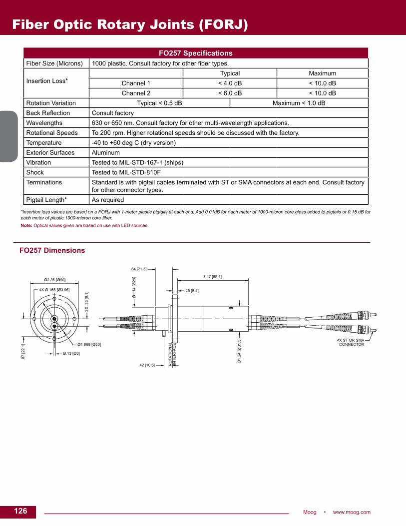
126 Moog • www.moog.com
Fiber Optic Rotary Joints (FORJ)
FO257 SpecificationsFiber Size (Microns) 1000 plastic. Consult factory for other fiber types.
Insertion Loss*Typical Maximum
Channel 1 < 4.0 dB < 10.0 dBChannel 2 < 6.0 dB < 10.0 dB
Rotation Variation Typical < 0.5 dB Maximum < 1.0 dBBack Reflection Consult factoryWavelengths 630 or 650 nm. Consult factory for other multi-wavelength applications.Rotational Speeds To 200 rpm. Higher rotational speeds should be discussed with the factory.Temperature -40 to +60 deg C (dry version)Exterior Surfaces AluminumVibration Tested to MIL-STD-167-1 (ships)Shock Tested to MIL-STD-810FTerminations Standard is with pigtail cables terminated with ST or SMA connectors at each end. Consult factory
for other connector types.Pigtail Length* As required
*Insertion loss values are based on a FORJ with 1-meter plastic pigtails at each end. Add 0.01dB for each meter of 1000-micron core glass added to pigtails or 0.15 dB for each meter of plastic 1000-micron core fiber. Note: Optical values given are based on use with LED sources.
FO257 Dimensions

127Moog • www.moog.com 127
FO292 Fiber optic rotary joint
DescriptionThe FO292 is an ultra-compact, two pass, multimode fiber optic rotary joint (FORJ). It is passive and bidirectional, and allows the transfer of optical signals on two separate optical fibers across rotational interfaces.
The FO292 can be combined with our electrical and fluid slip rings, giving a single, compact package for optical signals, electrical power and fluid transfer.
The FORJ can be assembled with pigtail lengths tailored to the customer’s application. Housing, mounting flange and drive features can also be customized to meet the customer’s requirements. The FO292 can also be installed with one or both ends having a 90° cable exit, providing even more flexibility when installing the unit into existing slip ring assemblies or installations with little clearance space.
Features• Provides rotary coupling for two multimode fibers• Passive and bidirectional• Can be combined with various electrical slip rings
and fluid unions • Smaller and more compact than the standard FO215
with improved back reflection performance• Customized mounting flanges available• Optional 90 degree cable exits at either end of the FORJ• Optional fluid-filled version for deep submergence to
10,000 psi (69,000 kPa)• Can be integrated into existing slip ring designs• Stainless steel housing• Rugged design - MIL-STD-167-1 ship vibration - MIL-STD-810E functional shock (40 g)
Typical Applications
• Winches and cable reels for remotely operated vehicles• Remote I / O in industrial machinery• Video surveillance systems• Material handling systems• Sensor platforms• Robots• Turrets
Fiber Optic Rotary Joints (FORJ)

128 Moog • www.moog.com
Fiber Optic Rotary Joints (FORJ)FO292 Specifications
Fiber Size (Microns) 50 / 125 or 62.5 / 125. Consult factory for other fiber types.
Insertion Loss*Typical Maximum
Channel 1 < 1.5 dB < 3.0 dBChannel 2 < 4.5 dB < 6.0 dB
Rotation Variation Typical < 0.5 dB Maximum < 1.0 dBBack Reflection Typical 20 dB 18 dB MinimumWavelengths 850, 1300 or 1550 nm. Consult factory for other multi-wavelength applications.Rotational Speeds To 500 rpm. Higher rotational speeds should be discussed with the factory.Temperature -40 to +60 deg C (dry version)
-20 to +60 deg C (wet version) Consult factory for extended range.Dispersion < 10 ps (calculated)Exterior Surfaces Stainless steelVibration Tested to MIL-STD-167-1 (ships)Shock Tested to MIL-STD-810FTerminations Standard is with pigtail cables terminated with ST connectors at each end. Alternative connectors
types available (FC, SC, LC).Pressure Up to 10000 psi (69,000 kPa) for fluid filled version**Pigtail Length* As required* Add 0.5 dB to the insertion loss to version with 90 degree cable exits.** Fluid filled version is slightly larger than shown below. Note: Optical values given are based on use with LED sources.
FO292 Dimensions
Dimensions in inches [millimeters]

129Moog • www.moog.com 129
FO242 Fiber optic rotary joint
DescriptionThe FO242 is a multi-pass, singlemode fiber optic rotary joint (FORJ). It is passive and bidirectional, and allows the transfer of optical signals across a rotational interface on 2 to 6 separate singlemode optical fibers.
The FO242 can be combined with our electrical and / or fluid slip rings giving a single, compact package for optical signals, electrical power and fluid transfer.
Other options include fluid-filling for pressure compensation permitting operation at any ocean depth, and the combination of the FO190 to include up to 19 multimode passes.
Features• 2 to 6 singlemode channels • Can be combined with our electrical slips, fluid unions and the FO190 multimode fiber optic rotary joint • Alternative drive coupling arrangements are available (consult factory for specification details) • Tested to 10,000 psi (69,000 kPa) when fluid-filled • Stainless steel and aluminum construction • Connectorized interfaces, for easy fiber cable replacement • Rugged design - MIL-STD-167-1 ship vibration - MIL-STD-810D functional shock (40 g)
Typical Applications
• Remotely operated vehicles• Floating production systems• Undersea telemetry• Seismic streamers• Radar antennas• Cable reels
Fiber Optic Rotary Joints (FORJ)

130 Moog • www.moog.com
FO242 SpecificationsFiber Size (Microns) 9 / 125 SMF-28
Insertion Loss (dB)
Channel 2-pass 3-pass 4-pass 5-pass 6-passTyp. Max. Typ. Max. Typ. Max. Typ. Max. Typ. Max.
1 2.0 3.0 2.0 3.0 2.0 3.0 2.0 3.0 2.0 3.02 2.5 4.0 2.5 4.0 2.5 4.0 2.5 4.0 2.5 4.03 2.5 4.5 3.5 5.0 3.5 5.0 3.5 5.04 4.0 5.5 5.0 6.5 5.0 6.55 5.5 6.5 6.0 6.56 6.5 7.5
Rotation Variation Typical < 0.5 dB Maximum < 1.5 dBBack Reflection* Typical 22 dB 18 dB MinimumWavelengths 1310 / 1550 nm. Consult factory for other wavelengths such as CWDM (18 wavelengths from 1271 nm to
1611 nm in 20 nm increments).Rotational Speeds To 100 rpm dry and 60 rpm fluid filled. Higher rotational speeds should be discussed with the factory.Temperature -40 to +60 deg C standard. Consult factory for extended range.Dispersion < 50 fs / nm (calculated)Exterior Surfaces Stainless steel and aluminumVibration Tested to MIL-STD-167-1 (ships)Shock Tested to MIL-STD-810EConnectors FC / PC connector bushings standard (ST connector bushings optional)Pressure Up to 10000 psi (69,000 kPa) for fluid filled versionPigtail Length As required
*Lower back reflection available, consult factory.
FO242 Dimensions
Dimensions in inches [millimeters]
Variation TableNo. Passes “L” Length
2 5.19 (132)3 6.91 (176)4 8.64 (220)5 10.37 (263)6 12.10 (307)
Fiber Optic Rotary Joints (FORJ)
REVISED 05/15

131Moog • www.moog.com 131
Fiber Optic Rotary Joints (FORJ)
Typical Applications
• Remotely operated vehicles• Floating production systems• Undersea telemetry• Seismic streamers• Radar antennas• Cable reels
FO291 Fiber optic rotary joint
DescriptionThe FO291 is a multi-pass, singlemode fiber optic rotary joint (FORJ). It is passive and bidirectional, and allows the transfer of optical signals across a rotational interface on 2 to 9 separate singlemode optical fibers.
The FO291 can be combined with our electrical and / or fluid slip rings, giving a single, compact package for optical signals, electrical power and fluid transfer, with ISO 9000 quality.
Other options include fluid-filling for pressure compensation permitting operation at any ocean depth, and the combination of the FO190 to include up to 19 multimode passes.
Features• 2 to 9 single mode channels• Can be combined with our electrical slip rings, fluid rotary unions
and the FO190 multimode fiber optic rotary joint• Alternative drive coupling arrangements are available (consult
factory for specification details)• Tested to 10,000 psi (69,000 kPa) when fluid-filled• Aluminum and stainless steel construction• Connectorized interfaces, for easy fiber cable replacement• Rugged design - MIL-STD-167-1 ship vibration - MIL-STD-810F functional shock (40g)

132 Moog • www.moog.com
FO291 SpecificationsFiber Size (Microns) 9 / 125 SMF-28
Insertion Loss (dB)*
(Typical / Maximum)
Includes RotationVariation
Channel 2-Pass 3-Pass 4-Pass 5-Pass 6-Pass 7-Pass 8-Pass 9-Pass
1 2.0/3.0 2.0/3.0 2.0/3.0 2.0/3.0 2.0/3.0 2.0/3.0 2.0/3.0 2.0/3.0
2 2.0/3.5 2.5/3.5 2.5/3.5 2.5/3.5 2.5/3.5 2.5/3.5 2.5/3.5 2.5/3.5
3 2.5/4.0 3.0/4.0 3.0/4.0 3.0/4.0 3.0/4.0 3.0/4.0 3.0/4.0
4 3.0/5.0 3.5/5.0 3.5/5.0 3.5/5.0 3.5/5.0 3.5/5.0
5 3.5/5.5 4.0/5.5 4.0/5.5 4.0/5.5 4.0/5.5
6 4.5/6.5 5.0/6.5 5.0/6.5 5.0/6.5
7 5.5/6.5 5.5/6.5 5.5/6.5
8 6.0/6.5 6.0/6.5
9 6.0/6.5
Rotation Variation Typical < 1.0 dB, maximum < 2.0 dB
Back Reflection** Typical > 22 dB, minimum > 18 dB
Wavelengths 1310 / 1550 nm. Consult factory for other wavelengths such as CWDM (18 wavelengths from 1271 nm to 1611 nm in 20 nm increments).
Rotational Speeds To 100 rpm dry and 60 rpm fluid filled. Consult factory for higher rotational speeds
Temperature -40 to +60 deg C standard. Consult factory for extended range
Dispersion < 50 fs / nm (calculated)
Exterior Surfaces Stainless steel and aluminum
Vibration Tested to MIL-STD-167-1 (Ships)
Shock Tested to MIL-STD-810F
Connectors FC / PC connector bushings standard (ST connector bushings optional)
Pressure Up to 10,000 psi (69,000 kPa) for fluid filled version
Pigtail Length FORJ is connectorized with FC / PC, ST optional. Pigtail length and connector type optional
*Insertion loss values include fiber cables attached at both ends of a connectorized FORJ.**Lower back reflection available, consult factory.
FO291 Dimensions
Fiber Optic Rotary Joints (FORJ)
Variation TableNo. Passes “ L” Length
2 3.82 (97)
3 4.70 (119)
4 5.59 (142)
5 6.47 (164)
6 7.36 (187)
7 8.24 (209)
8 9.13 (232)
9 10.01 (254)
REVISED 05/15
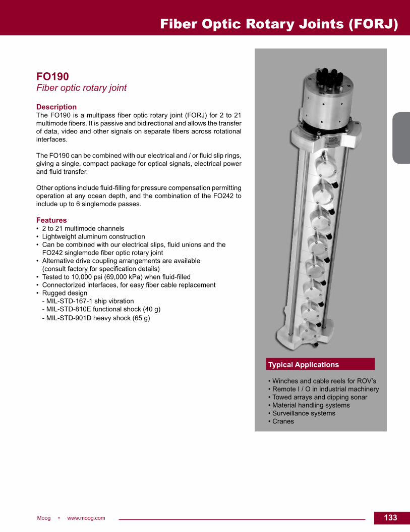
133Moog • www.moog.com 133
FO190 Fiber optic rotary joint
DescriptionThe FO190 is a multipass fiber optic rotary joint (FORJ) for 2 to 21 multimode fibers. It is passive and bidirectional and allows the transfer of data, video and other signals on separate fibers across rotational interfaces.
The FO190 can be combined with our electrical and / or fluid slip rings, giving a single, compact package for optical signals, electrical power and fluid transfer.
Other options include fluid-filling for pressure compensation permitting operation at any ocean depth, and the combination of the FO242 to include up to 6 singlemode passes.
Features• 2 to 21 multimode channels• Lightweight aluminum construction• Can be combined with our electrical slips, fluid unions and the FO242 singlemode fiber optic rotary joint• Alternative drive coupling arrangements are available (consult factory for specification details)• Tested to 10,000 psi (69,000 kPa) when fluid-filled• Connectorized interfaces, for easy fiber cable replacement• Rugged design - MIL-STD-167-1 ship vibration - MIL-STD-810E functional shock (40 g) - MIL-STD-901D heavy shock (65 g)
Typical Applications
• Winches and cable reels for ROV’s • Remote I / O in industrial machinery• Towed arrays and dipping sonar• Material handling systems• Surveillance systems• Cranes
Fiber Optic Rotary Joints (FORJ)

134 Moog • www.moog.com
FO190 Dimensions
FO190 Specifications Fiber Size (Microns) 50 / 125 or 62.5 / 125
Insertion Loss(Maximum Values)
<6.5 dB (50 / 125 fiber) <5.5 dB (62.5 / 125 fiber)
Rotation Variation <1.5 dB
Wavelengths 850, 1300 or 1550 nm. Consult factory for multi-wavelength applications.
Rotational SpeedsTo 100 rpm dry and 60 rpm fluid filled.Higher rotation speeds should be discussed with the factory.
Temperature -40 to +60 deg C
Dispersion < 10 picoseconds (calculated)
Return Loss < -18 dB
Vibration Tested to MIL-STD-167-1 (ships)
Shock Tested to MIL-STD-810E and MIL-STD-901D
Connectors FC / PC connector bushings standard. (ST connector bushings optional.)
Fiber Optic Rotary Joints (FORJ)
Note: Optical values given are based on use with LED sources.
Dimensions in inches [millimeters]

135Moog • www.moog.com 135
Fiber Optic Hybrid Units
H18 / H24 FORJFiber optic rotary joints
DescriptionThe H18 / H24 fiber optic rotary joints effectively combine a compact electrical slip ring with a fiber optic rotating joint. Both offer the flexibility of electrical, power and optical signal transfer through a single rotational joint. The H18 and H24 are low cost solutions for high data rate transmission to greater than 2.5 Gb / sec on the optical channel. Features• Combined compact electrical slip ring with fiber optic rotating joint• Flexibility of signal transfer through a single rotational joint• Low cost solution for high data rate transmission • Standard 18 or 24 circuit model with 2 amp circuits• Precision ball bearing for long life• Speeds up to 250 rpm continuous• Compact size• Metal housing available • Transfer analog and digital signals• Compatible with data bus protocols Benefits• Unique signal handling performance with minimal electrical
circuit noise• Tight packaging to fit in the most demanding space constraints• Low torque to minimize system torque budget• Rapid delivery
Typical Applications
• CCTV and dome camera manufacturing• Robotics• Upgrading legacy equipment• Digital communications and video

136 Moog • www.moog.com
Fiber Optic Hybrid Units
Dimensions in inches (millimeters)
Electrical CircuitsUp to 18 x 2 amps circuitsUp to 4 x 6 amps circuits Other combinations of the above available on requestPasses rated 240 V (28 AWG - silver plated)Continuous current rating based on number of current carrying conductors: 2 A for 1 - 3 conductors 1 A for 4 - 6 conductors 0.5 A for 7 - 18 conductors - H18 0.5 A for 7 - 24 conductors - H24
Rated Voltage210 VDC / 240 VAC
SpecificationsSinglemode
H1817-950 / H2418-950Multimode
H1810-950 / H2417-950Wavelengths 1310 and 1550 nm
(consult factory for multi-wavelength applications)850, 1310 and 1550 nm (consult factory for multi-wavelength applications)
Fiber Size 9 / 125 µm (consult factory for other sizes)
50 / 125 or 62.5 / 125 µm (consult factory for other sizes)
Insertion Loss <3.5 dB (typical: <1.5 dB) <2.5 dB (typical: <1.5 dB)Return Loss <-18 dB (standard). <-35 dB option available
(consult factory for details)<-18 dB
Rotation Variation <1.5 dB (typical <0.5 dB) <1.0 dB (typical <0.5 dB)Maximum Speed 500 rpm (consult factory for higher speeds) 500 rpm (consult factory for higher speeds)Terminations Pigtailed cable and connectors Pigtailed cable and connectorsJacket Type 900 µm 900 µm
Insulation Resistance 200 MΩ at 500 VAC
Electrical Cables Color coded, silver platedETFE or PTFE insulated lead wires
Temperature -20° to +60° C
Mounting Options Flanged as standardOther configurations available on request
BearingsPrecision ball bearings fitted throughout
H18 / H24 Dimensions
REVISED 08/15

137Moog • www.moog.com 137
Aerospace / Military Slip Ring Products
Moog • www.moog.com 137

138 Moog • www.moog.com
Electro-Optic Systems
DescriptionThe dramatic increase of sophisticated gimbaled electro-optic sensor systems that provide battlefield information has led to major developments in supporting hardware. These EO systems require an enormous amount of data to be transmitted across the rotating axes as well as power and other signals. Moog has always been one step ahead of these requirements with the development of high bandwidth slip rings, twist capsules, fiber optic rotary joints and multiplexing technologies.
Moog has participated in the development of many of the major airborne and groundbased EO systems The Abrams Tank Commander’s Independent Thermal Viewer (CITV) has used our slip ring assembly to allow continuous rotation on the azimuth axes since the program’s inception. The Bradley armored vehicle also uses Moog’s slip ring on the azimuth axis of its Commander’s Independent Viewer (CIV); in addition the CIV uses a Moog’s twist capsule on the elevation axis.
Moog slip rings and twist capsules are used extensively in airborne EO systems. The latest upgrade to the F-18 Hornet’s EO sensor suite, Advanced Targeting Forward Looking Infrared (ATFLIR), utilizes a Moog slip ring to allow continuous rotation in the roll axis and a twist capsule for scanning, or limited rotation, in the elevation and yaw axes. The Low Altitude Navigation and Targeting Infrared for Night (LANTIRN), and its successor Sniper, pods used for EO targeting and navigation on the F-16 uses Moog slip rings and twist capsules exclusively. The Predator UAV, LAMPS helicopter, and Apache helicopter all “see in the dark” because Moog hardware transmit data and power reliably.
Features• Multiple contact technologies suited for the application - Monofilament wire brush - Multiple precious metal fiber brush - Composite brush• Environmental sealing• EMI Shielding• FEA structure analysis• High shock and vibration capabilities• Wide operating temperature envelope• Vertical integration of position sensors and ancillary products• High frequency bandwidth• High reliability and life• Redundant bearing designs
Typical Applications
• Blade de-ice• Blade position• Tip lights• Flight controls• FLIR systems• Target acquisition systems• Weapon stations
Electro-Optic Systems

139Moog • www.moog.com 139
Electro-Optic Systems
Low Profile Azimuth Slip RingsSystem height is often the primary concern of the EO gimbal designer. Moog has the solution with its patented broadband platter slip ring design. This broadband technology allows the slip ring designer to package multiple high speed data lines on slip ring platters, and then “stack” these platters with their accompanying brush blocks into a very low profile design. Power rings as well as discrete signals and video can also be placed on these slip ring platters. This has led to a dramatic decrease in typical slip ring height or length over traditional slip ring “drum-style” designs.
High Speed DataThe dramatic improvement in image quality, the use of multi-sensors, and increased communication requirements have driven the need for EO Systems to significantly increase transmission speeds of data channels with every generation of upgrade. We have EO slip rings that handle as many as two dozen data channels at over 400 Mbps each, for an aggregate bandwidth of 12 Gpbs. Slip ring/fiber optic rotary joint
hybrid designs contain both copper lines for power and signals, as well as fiber lines for fiber optic signals.
Design and manufacturing techniques have been developed and patented that increase signal bandwidth while controlling crosstalk and EMI/EMC. A arrange of solutions is available to handle data channels such as GigE, Fibre Channel, and IEEE1394 to name just a few. These high speed data solutions are being used in existing EO system as well as turret, radar, and other advanced technology applications.
Poly-Twist or Twist CapsulesIn most cases gimbaled EO systems require continuous, unlimited rotation on just one axis, typically the azimuth or roll axis. In this case slip rings are the ideal solution for transmitting signals across the rotating interface. Normally the other axes (pitch, elevation, or yaw), require only limited rotation, i.e., less than 360 degrees. This allows the use of a Poly-Twist to transmit electrical power and signals. By the use of wrapping flexible circuits , the Poly-Twist designer is able to increase circuit density, decrease weight, and improve system reliability over traditional cable wraps. The long life, low and consistent torque, and the small size make Poly-Twists the best solution for scanning, or limited rotation axes in EO systems.
ELECTRO-OPTIC SYSTEMS SLIP RING DESIGNS
Poly-Twists—How They WorkPoly-Twists resemble slip ring assemblies in size and appearance and provide multiple turns of rational freedom. They operate by winding and unwinding flexible circuit tapes wrapped around a central shaft in a configuration resembling a clock spring. The central shaft is generally supported by ball bearings, but bearing-less assemblies are available. One end of the shaft is fastened to the shaft, with lead wires extending from the shaft either axially or radially. The other end of the tape is fastened to the Poly-Twist frame, which is usually considered stationary. Stator lead wire terminations may also be either axial or radial. The flexing element is the key to the low torque and long life of the Poly-Twist. The stress on the flexible circuit is well below its endurance stress limit producing very low torque levels and very long operational life.
Dimensions in inches (millimeters)
Electro-Optic System Slip Ring Design

140 Moog • www.moog.com
Vehicular Slip RingsReliable signal and power coupling in the most rugged battlefield conditions
DescriptionThe increasing complexity of modern military vehicles demands slip rings that provide reliable electrical interfaces between the stationary and rotating parts of these vehicles. Moog slip rings have been chosen to operate on numerous vehicular programs to meet these challenges. M1 / A2 and M60 tanks, A2 / A3 Bradley Fighting Vehicles, Stryker, Light Armored Vehicles (LAVs), and V150 Commando Vehicles are just a small sample of these vehicular programs.
Technological developments have yielded stabilized gun systems, laser target acquisition and fire control systems, and high bandwidth data communications that create unique demands for vehicular slip rings. We meet all of these challenges effectively and economically. A sampling of our many active vehicular slip ring designs are shown on the following pages, or our engineering department can tailor a slip ring for your vehicular application, often within the existing envelope. Contact us with your requirements.
Features• Supports modern data communication technologies• Full environmental sealing capabilities• EMI shielding available• Range of operating voltages compatible with any vehicular system• Hydraulic rotary joint options• Gold-on-gold contacts for signal and data integrity• Meets military shock and vibration requirements• Speed, torque and frequency characteristics designed for specific
vehicular applications• High power capability to support present and future vehicular
system needs• High frequency coax channels available• Through-bore designs• Cam-operated microswitches• Vertical integration with resolvers, fiber optics, fluidic interfaces,
hydraulics, pneumatics and motors• Filtered air transfer for chemical, biological and radiological (NBC)
requirements and / or electronics cooling and pneumatic rotary joint options for crew station breathing and electronic cooling
• High speed data capabilities
Vehicular Slip Rings
Typical Applications
• Tanks• Light armored vehicles• Armored personnel carriers• Retrievers• Armored field artillery vehicles• Brigade command vehicles• Reconnaissance vehicles• Mobile missile launchers• Independently rotating commander stations • Forward-Looking-Infra-Red systems (FLIRs) or viewers

141Moog • www.moog.com 141
Vehicular Slip Rings
VEHICULAR SLIP RING DESIGN CRITERIA
Electrical slip rings are used in vehicles such as tanks, retrievers, light armored vehicles, mobile missile launchers, and armored personnel carriers. A typical vehicle might contain slip rings in the turret, the commander station and the infrared sight. In each of these systems, slip rings have provided reliable signal and power coupling under the most rugged battlefield conditions.
In addition to producing compact slip rings where minimal space is available, we have provided units that combine conventional electrical slip rings with resolvers, encoders, fiber optics, pneumatics and hydraulics rotary joints.
DesignMoog can offer the most valuable design assistance by being involved early in the development of the vehicle. The internal design of the slip ring capsule will be driven by the circuit requirements and the space available for mounting the slip ring capsule. From our vast product line, we can pull from the following design criteria: • use of existing designs• single drum• concentric drums• single pancake• stacked pancakes• combination of designs
• clear through-bore to allow another device to occupy the centerline
• connectors – case mounted or attached to cables• mechanical support – on either side of the
rotating interface.
Power CircuitsTheoretically, there is no limit to the amount of power that can be transferred by the slip ring capsule. Most hull-to-turret slip ring capsules are capable of transferring 150 amps continuously. It is important that the power duty cycles (including surge currents) be accurately defined as early as possible in the design stage. (Requiring the slip ring capsule to operate at continuous current levels that will not be encountered in the field takes space that could be more effectively used for signal requirements.) If the space available for the slip ring capsule is limited, it may be advantageous to transfer the power at higher voltages and lower currents. The power ground can be made through the case of the slip ring capsule or insulated from case ground.
Signal CircuitsSignal requirements for vehicular slip ring capsules continue to be increasingly demanding. The circuit functions and
electrical isolation requirements have a significant impact on the design of the slip ring capsule. A typical vehicular slip ring will include circuits for powering electronic equipment, video circuits, and analog and digital control circuits.
Sometimes it is important that sensitive circuits have additional isolation from other circuits to meet heightened sensitivity requirements. Circuit isolation requirements are more easily addressed early in the design stages.
Slip Ring ExpertiseVehicles such as tanks, retrievers, mobile missile launchers, light armored vehicles and armored personnel carriers pose a variety of challenges. Hydraulically-actuated equipment in the turret may require the combination of conventional electrical slip ring with a hydraulic joint to form an electro-hydraulic slip ring, thereby providing reliable fluidic interfacing. The threat of a NBC environment may require pneumatic channels through the slip ring to provide filtered air to crewmembers’ facemasks. The introduction of an independently rotating commander station or cupola may require a slip ring large enough in diameter to encompass the station, yet very thin in cross section to minimize
Components for Vehicular Systems
FLIRs and TargetAcquisition Systems• Slip ring• Resolver• Cube motor• Torque motor• Actuator
Motors, Resolvers and Actuators• Electric turret drive• Gun elevation• Travel lock
Turret Slip RIngs• Electromechanical or• Electro-optical• Hydraulic• Pneumatic
Optical Data Bus• Fiber optic rotary joint - On and off axis - Single and mulit channel - Single and multi mode• FDDI bypass switches• Trunk coupling units
Turret Stabilization• Moog Systems Group
Weapon Station Cupola• Slip ring• Resolver• Motor• Actuator

142 Moog • www.moog.com
Vehicular Slip Rings
The following table presents a cross-section of our vehicular designs. These products are for reference purposes only. Please contact the factory concerning your requirements. Tooling charges may apply.
space requirements. These advances in military technology, plus many others, have challenged the capabilities of the slip ring industry, demanding equally sophisticated solutions for reliable vehicle operation.
Moog consistently meets these challenges successfully and economically. For more than 50 years we have been involved in the design, development, and production of quality slip rings for many diverse applications. Recognized as leaders in slip ring research and testing, our team of engineers, scientists, and manufacturing personnel have focused their total resources toward one goal—providing you with the best possible product.
To that end, we have:• Established a complete Research &
Development team, conducting numerous on-going studies in such areas as tribology—the science of friction, wear and high bandwidth communication.
• Studied the effect of environmentally-induced contaminants on sl ip r ing contacts and made substantial progress in making slip rings more tolerant of hostile environments.
• Consolidated all of the functions of product design, tool design, manufacturing, and product testing into a well-integrated in-house operation certified to AS9100 Rev. C ISO 9001-2008.
• Combined field-proven slip ring designs with high-volume tooling techniques resulting in high quality hull-to-turret slip rings at attractive unit prices.
• Presented technical papers dealing with the field of electrical contacts and the applications of our technology to a diverse marketplace.
In view of our many years of applicationsexperience and proven performance, it is
Vehicular and Turret Slip Ring Specifications
easy to understand why our slip rings havebeen chosen to be used on numerousvehicular programs, including:
• APC • 8x8• M60 A1 & A2 • M728 CEV• HSTV • Centurion• M2 & M3 Bradley • Commando V150• Leopard • Stryker• M48 • AAV• LAV • Bionix
VEHICULAR SLIP RING DESIGN CRITERIA
VehicularSlip Ring
Power Signal Comments
Number of Circuits
Cont. Current Rating
Voltage Rating
Number of Circuits
Gauge or Type Intended Signal
AC3497 11
150 amps150 amps
Ground 12 Control 5 amps, 150 V 2 cam design for dual fire controlVariations available
AC6033 11
150 amps150 amps
Ground 18 Control 5 28 VDC Dual cam NBC air channelVariations available
VSR-3733 2 200 amps 24 VDC 42 20 AWG 3 amps, 28 VDC NBC air channelSize similar to VSR4994
VSR-4906 2 200 amps 24 VDC 61 20 AWG 3 28 VDC, 28 VDC NBC air channelSize similar to VSR4994
VSR-4994 4 200 amps 24 VDC 86 24 AWG 2 - 4 amps, 28 VDC NBC air channel(2) 1553 Data-bus(8) RS-170 Video
VSR-6057 2 250 amps 18 - 32 VDC 238 24 AWG 2 - 4 28 VDC, 28 VDC EMI features concentric rings and high isolation
VSR-6772 22
450 amps75 amps
28 VDC28 VDC
150 28 AWG 100 Mbit Ethernet Contains resolver, R to D network, power distribution network and pneumatic and hydraulic rotary joint
VSR-2000 2 50 amps 250 VDC 12 or 24 10 amps, 250 VDC High current and alternate signal configurations available
VSR-7001 24411
150 amps120 amps80 amps13 amps
20 - 33 VDC20 - 33 VDC20 - 33 VDC20 - 33 VDC
3218634
22 AWG24 AWG28 AWG TwinaxMIL-C-17 / 9428 AWG Twinax
5 amps, 20 - 33 VDC3 amps, 20 - 33 VDCSerial DataRG-179Gigabit Ethernet
Gigabit ethernet channelsImmersible to 1 meter(2) RS-170 videoAir channel

143Moog • www.moog.com 143
Vehicular Slip RingsTypical Vehicular Slip Ring Designs
AC3497
AC6033
VSR-3733

144 Moog • www.moog.com
VSR-4994
Typical Vehicular Slip Ring Designs
Vehicular Slip Rings
VSR-4906
VSR-6057

145Moog • www.moog.com 145
Vehicular Slip Rings
VSR-6772
Typical Vehicular Slip Ring Designs
VSR-2000
VSR-7001

146 Moog • www.moog.com
Helicopter Slip RingsProven reliability in the most demanding of applications and environments
DescriptionToday’s rotorcraft applications place unique demands on slip ring technology because of equipment requirements and environmental conditions. From de-ice applications (with their need for high rotational speed, exposure to weather conditions and high vibration) to weapon stations and electro-optic sensor systems (with high bandwidth signal transmission), helicopter slip rings must perform in a highly reliable mode with the latest product advancements.
Our many years of experience in this arena has allowed Moog to be a leader in slip ring technology for rotorcraft applications. Employing a combination of precious metal fiber and composite brush technology for signal and power transfer, we are qualified to meet the most demanding applications effectively and economically. Contact us with your requirements so we can help you find a solution.
Features• Multiple contact technologies suited for the application - Monofilament wire brush - Multiple precious metal fiber brush - Composite brush• Environmental sealing• EMI Shielding• FEA structure analysis• High shock and vibration capabilities• Wide operating temperature envelope• Vertical integration of position sensors and ancillary products• High frequency bandwidth• High reliability and life• Redundant bearing designs
Typical Applications
• Blade de-ice• Blade position• Tip lights• Flight controls• FLIR systems• Target acquisition systems• Weapon stations
Helicopter Slip Rings
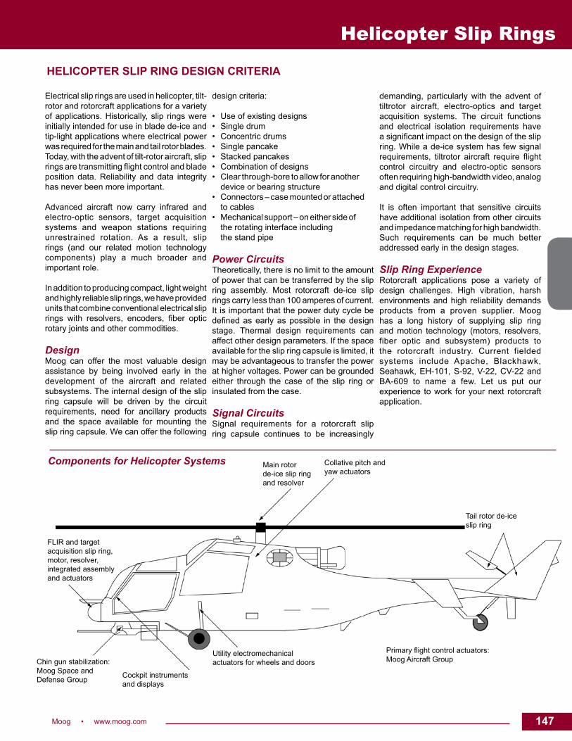
147Moog • www.moog.com 147
Components for Helicopter Systems Main rotor de-ice slip ring and resolver
Collative pitch and yaw actuators
Tail rotor de-ice slip ring
Primary flight control actuators: Moog Aircraft Group
Utility electromechanical actuators for wheels and doors
Cockpit instruments and displays
Chin gun stabilization:Moog Space and Defense Group
FLIR and target acquisition slip ring, motor, resolver, integrated assembly and actuators
Electrical slip rings are used in helicopter, tilt-rotor and rotorcraft applications for a variety of applications. Historically, slip rings were initially intended for use in blade de-ice and tip-light applications where electrical power was required for the main and tail rotor blades. Today, with the advent of tilt-rotor aircraft, slip rings are transmitting flight control and blade position data. Reliability and data integrity has never been more important.
Advanced aircraft now carry infrared and electro-optic sensors, target acquisition systems and weapon stations requiring unrestrained rotation. As a result, slip rings (and our related motion technology components) play a much broader and important role.
In addition to producing compact, light weight and highly reliable slip rings, we have provided units that combine conventional electrical slip rings with resolvers, encoders, fiber optic rotary joints and other commodities.
DesignMoog can offer the most valuable design assistance by being involved early in the development of the aircraft and related subsystems. The internal design of the slip ring capsule will be driven by the circuit requirements, need for ancillary products and the space available for mounting the slip ring capsule. We can offer the following
design criteria:
• Use of existing designs• Single drum• Concentric drums• Single pancake• Stacked pancakes• Combination of designs• Clear through-bore to allow for another device or bearing structure • Connectors – case mounted or attached to cables• Mechanical support – on either side of the rotating interface including the stand pipe
Power CircuitsTheoretically, there is no limit to the amount of power that can be transferred by the slip ring assembly. Most rotorcraft de-ice slip rings carry less than 100 amperes of current. It is important that the power duty cycle be defined as early as possible in the design stage. Thermal design requirements can affect other design parameters. If the space available for the slip ring capsule is limited, it may be advantageous to transfer the power at higher voltages. Power can be grounded either through the case of the slip ring or insulated from the case.
Signal CircuitsSignal requirements for a rotorcraft slip ring capsule continues to be increasingly
demanding, particularly with the advent of tiltrotor aircraft, electro-optics and target acquisition systems. The circuit functions and electrical isolation requirements have a significant impact on the design of the slip ring. While a de-ice system has few signal requirements, tiltrotor aircraft require flight control circuitry and electro-optic sensors often requiring high-bandwidth video, analog and digital control circuitry.
It is often important that sensitive circuits have additional isolation from other circuits and impedance matching for high bandwidth. Such requirements can be much better addressed early in the design stages.
Slip Ring ExperienceRotorcraft applications pose a variety of design challenges. High vibration, harsh environments and high reliability demands products from a proven supplier. Moog has a long history of supplying slip ring and motion technology (motors, resolvers, fiber optic and subsystem) products to the rotorcraft industry. Current fielded systems include Apache, Blackhawk, Seahawk, EH-101, S-92, V-22, CV-22 and BA-609 to name a few. Let us put our experience to work for your next rotorcraft application.
Helicopter Slip Rings
HELICOPTER SLIP RING DESIGN CRITERIA

148 Moog • www.moog.com
Propeller Slip Rings
DescriptionFixed wing propeller aircraft use special de-icing slip rings to pass electrical power from the airframe generators to the rotating propellers. These propellers are heated to avoid the build up of ice either in flight or on the ground in difficult weather conditions.
The correct choice of materials for the rings and brushes, together with a very fine surface finish on the rings themselves, ensure the optimum life of the unit in operation. The life time is generally in excess of 1500 hours at 1200 rpm – equivalent to >100 million revolutions, with only a simple maintenance operation to change the brushes and brush block.
Units are designed for each application in conjunction with the customers’ requirements.
Typically these slip rings are supplied to the Propeller system manufacturer.
Moog pedigree extends over many years and the following programmes are examples of where our products are used :
- Jetstream - Fokker 50 - SAAB 340 - Grumman - SAAB 2000 - De Havilland Dash 8 - Lockheed Martin C130J - ATR42 - Airbus A400M
Features• Low brush wear• Integrated rings and housings• Beryllium free design• Low maintenance solution, replacable brushes• Diamond turned finish on the slip ring
Typical Applications
• Blade de-ice
Propeller Slip Rings

149Moog • www.moog.com 149
Propeller Slip Rings
Typical Propeller Slip Ring Dimensions
Dimensions in millimeters (inches)

150 Moog • www.moog.com
Miniature Slip Ring Capsules
AC264AC267Miniature slip ring capsules in various circuit configurations
DescriptionA slip ring capsule can be used in any electromechanical system that requires unrestrained, intermittent or continuous rotation while transferring power and / or data.
Miniature slip ring capsule assemblies economically address both critical space and weight limitations. Each assembly includes the rotor, brush blocks, frame, ball bearings and dust cover. Existing designs are available or we can custom design slip rings to meet your specific requirement.
Although originally designed for commercial uses, the miniature slip ring capsule is well suited for many military applications.
Features• Rugged stainless steel housing• Up to 60 rings can be packaged in a self-contained
envelope 1.957 inch long and .50 inch barrel diameter• Gold-on-gold sliding contact technology• Up to 100 rpm operation• Low noise; as low as 25 milliohms• Long life. Several million total revolutions at speeds up
to 60 rpm have been obtained.
Benefits• Precise, tight packaging capabilities for meeting stringent design
criteria• Proprietary plating techniques provide improved reliability, longer
life and increased efficiency• Unique signal handling performance to minimize noise and increase
speed• Configuration flexibility allows for packaging from 16 to 60 circuits
Typical Applications
This slip ring provides high speed performance and is successfully serving in various applications such as:
• Gimballed pitch, roll and yaw axes of inertial navigation systems
• Unmanned Aerial Vehicles (UAV)

151Moog • www.moog.com 151
Miniature Slip Ring Capsules
Dimensions in inches (millimeters)
AC264 Specifications Current Rating .8 amp per circuit Lead Size 30 AWG Dielectric Strength 500 VAC (test) Insulation Resistance 1000 mohms @ 500 VDC Circuit Resistance 265 mohms with 12 in. leads both ends Starting Torque 2 grams-centimeters max. per circuit Noise 50 mohms tested @ 5 rpm test current 50 MA
No. of Circuits “A” Dimension “B” Dimension
20 1.04 (26.3) 0.757 (19.2) 30 1.34 (33.9) 1.057 (26.8) 40 1.64 (41.5) 1.357 (34.5) 50 1.94 (49.1) 1.657 (42.1) 60 2.24 (56.8) 1.957 (49.7)a
AC267 Dimensions
AC267 Specifications Current Rating .8 amp per circuit
Lead Size 30 AWG Dielectric Strength 500 VAC (test) Insulation Resistance 1000 mohms @ 500 VDC Circuit Resistance 270 mohms with 12 in. leads both ends Starting Torque 1.5 grams-centimeters max. per circuit Noise 25 mohms tested @ 5 rpm with test current 100 MA
No. of Circuits “A” Dimension “B” Dimension
16 0.91 (23.2) 0.71 (18.0) 20 1.03 (26.2) 0.83 (21.0) 24 1.15 (29.3) 0.95 (24.1) 28 1.27 (32.3) 1.07 (27.1) 32 1.39 (35.4) 1.19 (30.2) 36 1.51 (38.4) 1.31 (33.2)
AC264 Dimensions
Dimensions in inches (millimeters)

152 Moog • www.moog.com
Miniature Slip Ring Capsules
RE4815Miniature slip ring capsule in a compactconfiguration for demanding applications
DescriptionA slip ring capsule can be used in an electromechanical application to transfer low power and data over a continuous rotary interface, eliminating the need for wrapped cables. The RE4815 provides highly compact packaging to 32 conductors in a very small 1/2 inch diameter housing with an overall length of less than 1-3/8 inches.
Features• Compact for ease of incorporation in small mechanisms• 32 rings with excellent signal handling properties as well as low power transfer• Gold-on-gold contact technology• Up to 600 rpm operation• Low electrical noise
Benefits• Highly compact to keep mechanisms small• Outstanding signal handling capability to transfer the most demanding communication protocols• Proprietary plating techniques and materials for high performance and reliability• Rugged stainless steel housing for demanding environments
Typical Applications • Gimble systems• UAV camera systems• Positioning tables• Laboratory equipment

153Moog • www.moog.com 153
Miniature Slip Ring Capsules
RE4815 SpecificationsCurrent Rating 1 A per circuitOperational Voltage 50 VAC / VDCLead Size 30 AWG (19 / 42 SPC, Teflon® insulation)Starting Torque 50 gm cmElectrical Noise 50 milliohms maximum tested @ 6 VDC
50 milliamps when running @ 130 rpmOperational Temperature 80°C maximumRotational Speed 600 rpmCircuit Resistance 900 milliohms maximumEnclosure Stainless steel
RE4815 Dimensions
Dimensions in inches (mm)
Lead Color Codes1 BLK 9 GRY 17 WHT/BLU 25 WHT/BLK/BLU2 BRN 10 WHT 18 WHT/VIO 26 WHT/BLK/VIO3 RED 11 WHT/BLK 19 WHT/GRY 27 WHT/BLK/GRY4 ORN 12 WHT/BRN 20 WHT/BLK/BRN 28 WHT/BRN/RED5 YEL 13 WHT/RED 21 WHT/BLK/RED 29 WHT/BRN/ORN6 GRN 14 WHT-ORN 22 WHT/BLK/ORN 30 WHT/BRN/YEL7 BLU 15 WHT/YEL 23 WHT/BLK/YEL 31 WHT/BRN/GRN8 VIO 16 WHT/GRN 24 WHT/BLK/GRN 32 WHT/BRN/BLU
REVISED 08/16

154 Moog • www.moog.com
AC6292Miniature slip ring capsule - circuit configuration for commercial and military applications
DescriptionA slip ring capsule can be used in any electromechanical system that requires unrestrained, occasional or continuous rotation while transferring power and / or data.
Miniature slip ring capsule assemblies economically address both critical space and weight limitations. Each assembly includes the rotor, brush blocks, frame, ball bearings and dust cover.
These slip rings can be configured with spacing between rings of 0.006 inch and brush diameters no larger than a human hair. Existing designs are available or we can custom design slip rings to meet your specific requirement.
Features• Center-to-center adjacent ring spacings as small as 0.015 inch can be obtained• 80 rings packaged in a self-contained envelope 2.0 inches long and .68 inch barrel diameter• Gold-on-gold sliding contact technology• Up to 40 rpm operation• Low noise; as low as 15 milliohm per circuit pair• Long life; several million total revolutions have been obtained
Benefits• Precise, tight packaging capabilities for meeting stringent design criteria• Proprietary plating techniques provide improved reliability, longer life and increased efficiency• Unique signal handling performance to minimize noise and increase speed• Other configurations are available from 16 to 95 circuits• We also manufacture commercial slip rings from 6 to 56 circuits
Typical Applications
• Gimballed pitch, roll and yaw axes of inertial navigation
systems• Unmanned Aerial Vehicles (UAV)• Airborne camera platforms
Miniature Slip Ring Capsules

155Moog • www.moog.com 155
Miniature Slip Ring Capsules
Dimensions in inches
AC6292 Dimensions
AC6292 SpecificationsLead Size 30 AWG / 26 AWGDielectric Strength 500 VAC (test)Insulation Resistance 1000 megohmsCircuit Resistance 0.54 ohms (leads @ 24 in.)Starting Torque 240 gm cmNoise 30 milliohms max.Rotational Speed 40 rpm max.Lead Length 24 inches each end
REVISED 08/16

156 Moog • www.moog.com
Miniature Slip Ring Capsules
RK4288Miniature slip ring capsulecircuit configuration for commercial and military applications
DescriptionA slip ring capsule can be used in any electromechanical system that requires unrestrained, occasional or continuous rotation while transferring power and / or data.
Miniature slip ring capsule assemblies economically address both critical space and weight limitations. Each assembly includes the rotor, brush blocks, frame, ball bearings and dust cover.
These slip rings can be configured with spacing between rings of 0.015 inch and brush diameters no larger than a human hair. Existing designs are available or we can custom design slip rings to meet your specific requirement.
Features• Center-to-center adjacent ring spacings as small as 0.015 inch can be obtained• 95 rings packaged in a self-contained envelope 3.3 inches long and 1.5 inch barrel diameter• Gold-on-gold sliding contact technology• Up to 40 rpm operation• Low noise; as low as 15 milliohm per circuit pair• Long life; several million total revolutions have been obtained
Benefits• Precise, tight packaging capabilities for meeting stringent design criteria• Proprietary plating techniques provide improved reliability, longer life and increased efficiency• Unique signal handling performance to minimize noise and increase speed• Other configurations are available from 16 to 80 circuits• We also manufacture commercial slip rings from 6 to 24 circuits
Typical Applications
This slip ring provides high speed performance and is successfully serving in applications such as:
• Gimballed pitch, roll and yaw axes of inertial navigation systems
• Satellite de-spin assemblies• Deep earth drilling projects• Unmanned Aerial Vehicles (UAV)• Airborne camera platforms

157Moog • www.moog.com 157
Miniature Slip Ring Capsules
RK4288 Dimensions
RK4288 SpecificationsCurrent Rating 0.8 amp per circuitLead Size 30 AWGDielectric Strength 500 V (test)Insulation Resistance 1000 Mohms @ 500 VDCCircuit Resistance 0.54 ohms (leads @ 24 in.)Starting Torque 240 gm cmNoise 30 milliohms max.Rotational Speed 40 rpm max.Lead Length 24 inches each end
Dimensions in inches (millimeters)
REVISED 08/16

158 Moog • www.moog.com
Miniature Slip Ring Capsules
Typical Miniature Slip Ring Capsule Designs
SJ4834
AC6449
Part # No. of Ckts.
Signal Power Length (inch) O.D. Housing (inch) O.D. Flange Other
RT4922 5 5 @ 1A 0 1.10 0.47” 0.87” 1 segmented circuit
SJ4834 8 5 @ 1A 3 @ 4A 1.90 0.75” 1.56” Integral rotor connector
JJ6095 15 15 @ 1A 1.1 1.0” 1.4” O’ring, sealed bearing, fiber brush
GS2725 29 23 @ 0.5A 6 @ 2A 0.83 0.39” 1.24” Lead length is 11 in. min.
RE4815 32 32 @ 1A 0 1.32 0.50” 0.60” Lead length is 24 in. rotor & 12 in. stator
GS2388 38 38 @ 1A 0 1.0 0.41” 1.26” Rotor leads: 12 in.; brush block leads 8 in.
BB3199 39 39 @ 1A 0 1.03 0.59” 0.65” 24/12 in. lead length
BB2759 45 45 @ 1A 0 1.03 0.59” 0.65” Rotor leads: 24 in.; brush block leads 12 in.
NH3302 60 60 @ 1A 0 2.24 0.50” 0.75” Lead length is 12 in.
BB2871 65 65 @ 1A 0 1.28 0.65” 0.64” Higher voltage on 5 ckts
AC6449 74 66 @ 1A 8 @ 3A 1.26 1.75” 2.25” Concentric unit
AC6292 80 57@ 1 A 23 @ 2A 2.00 0.68” 1.15” COTS - export w/out license
RK4288 95 95 @ 1A 0 3.3 0.88” 1.50” Lead length is 24 in.
REVISED 08/16

159Moog • www.moog.com 159
Miniature Slip Ring Capsules
M SeriesSlip ring capsules
DescriptionThe M series of slip ring assemblies were developed for a wide variety of applications and environments. The M series is an ideal choice for limited space applications. As many as 120 separate circuits are accommodated in a 2.7 inch diameter OD envelope and in less than 5.50 inches long. These slip ring assemblies are a quick turn solution for your application. Off the shelf components allow for a delivery which meets your needs.
Features• Ideal for limited space applications• Modular construction for up to 120 circuits• All circuits 60 V / 2 A each• Continuous bidirectional rotation up to 1,000 rpm• Dust-proof cover standard• Flange mounting• Superior signal quality• 24 inch flying leads, optional wiring and harnessing available• #26 AWG lead wire
Typical Applications
• Surveillence equipment

160 Moog • www.moog.com
Miniature Slip Ring Capsules
M Series Specifications OptionsCircuits Up to 120 circuits: 2 A / 60 volts • Longer leads
• Special wiring • Fiber optic rotary joint• High voltage option to 120 V
Maximum Speed 1000 RPMTerminals #26 AWG flying leadsMounting Flange mounting
Part Number Number of Circuits “L”1021202-1 40 2.801021202-2 80 4.151021202-3 120 5.50
M Series Dimensions
Dimensions in inches (millimeters)

161Moog • www.moog.com 161
Marine / Energy Slip Rings
Moog • www.moog.com 161
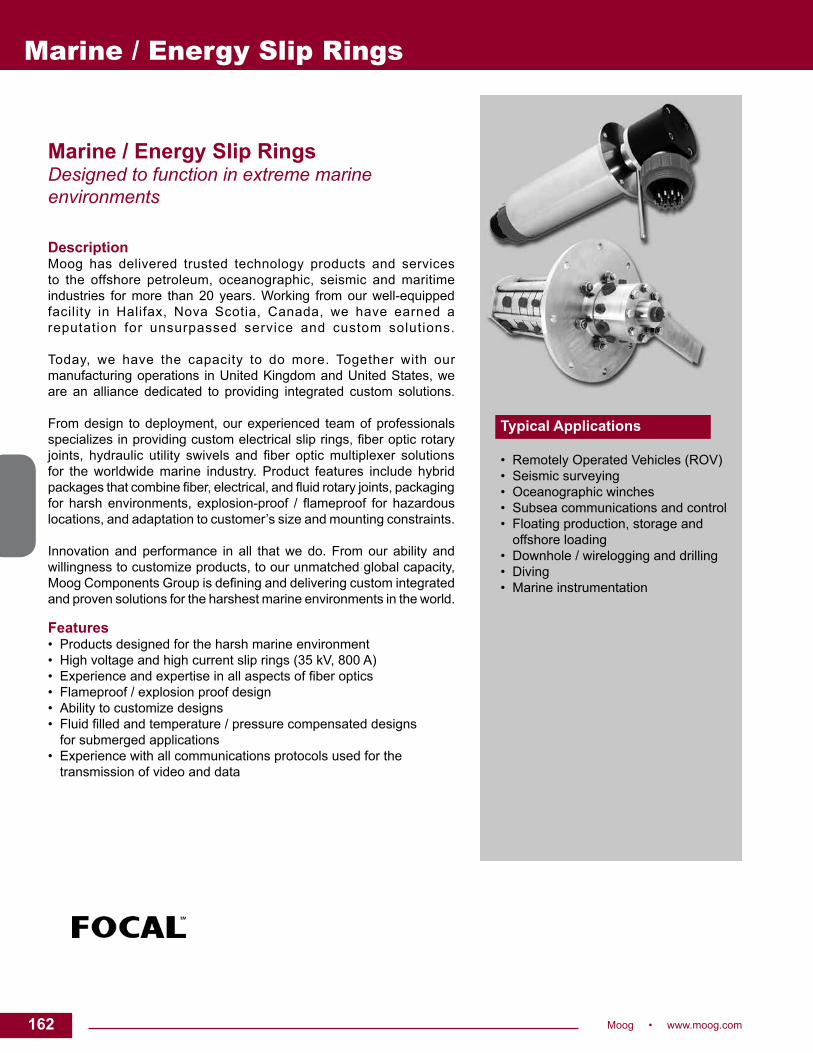
162 Moog • www.moog.com
Marine / Energy Slip RingsDesigned to function in extreme marine environments
DescriptionMoog has delivered trusted technology products and services to the offshore petroleum, oceanographic, seismic and maritime industries for more than 20 years. Working from our well-equipped facility in Halifax, Nova Scotia, Canada, we have earned a reputation for unsurpassed service and custom solutions. Today, we have the capacity to do more. Together with our manufacturing operations in United Kingdom and United States, we are an alliance dedicated to providing integrated custom solutions. From design to deployment, our experienced team of professionals specializes in providing custom electrical slip rings, fiber optic rotary joints, hydraulic utility swivels and fiber optic multiplexer solutions for the worldwide marine industry. Product features include hybrid packages that combine fiber, electrical, and fluid rotary joints, packaging for harsh environments, explosion-proof / flameproof for hazardous locations, and adaptation to customer’s size and mounting constraints. Innovation and performance in all that we do. From our ability and willingness to customize products, to our unmatched global capacity, Moog Components Group is defining and delivering custom integrated and proven solutions for the harshest marine environments in the world. Features • Products designed for the harsh marine environment• High voltage and high current slip rings (35 kV, 800 A) • Experience and expertise in all aspects of fiber optics• Flameproof / explosion proof design• Ability to customize designs• Fluid filled and temperature / pressure compensated designs for submerged applications• Experience with all communications protocols used for the transmission of video and data
Typical Applications • Remotely Operated Vehicles (ROV)• Seismic surveying• Oceanographic winches• Subsea communications and control• Floating production, storage and offshore loading• Downhole / wirelogging and drilling• Diving• Marine instrumentation
Marine / Energy Slip Rings

163Moog • www.moog.com 163
Slip Rings
Model 129 Slip ring
DescriptionThe Model 129 is a power slip ring used in marine and industrial applications worldwide. When rugged environments demand reliable, continuous operating performance, the 129 is the slip ring of choice. Capable of transmitting up to 5000 volts and 150 amps per slip ring pass, the 129 can reliably transfer power across a rotating interface.
Features• Stainless steel housing provided for rugged environments• Hazardousareacertificationavailable• Power and signal transfer integrated into a single unit
Benefits• Each unit designed, manufactured, and tested in accordance with
the highest quality standards• Maintenance free operation• Proven reliable, long life performance• Integrationwithfiberopticrotaryjointsandfluidrotaryunionsto
provide a complete rotating interface solution
Typical Applications
• Industrial machinery• FPSO swivel stacks

164 Moog • www.moog.com
Slip Rings
Dimensions in inches [millimeters]
Model 129 Dimensions
ElectricalVoltage Maximum 5000 VACCurrent Maximum 150 A per pass 1
Maximumcurrentnotspecified 2
1 Higher current ratings possible by wiring passes in parallel2 All current ratings based on a 20 °C ambient temperature
MechanicalRotation Speed Maximum 50 rpm continuous 1
Protection Class IP 66Operating Temperature -20 °C to + 55 °C 2
Housing Stainless steel (304)Length “L” Varies with number of electrical
passes 1 Higher rotational speeds possible. Please consult factory.
Hazardous Area Option: Model 129XCSA Certification Class 1, Group C, DKEMA Certification(Model 295-X)
ATEX II 2 G EEx d IIB T5 (in accordance with ATEX directive 94 / 9 / EC)
Canbesuppliedwithpurgefittingsforusewithacertifiedpurgesystem
Additional OptionsFiber Optics Fiber Optic Rotary Joint (FORJ) or
Optical ConverterFluid Fluid Rotary Union (FRU)Design Certification
ABS, DNV, BV, LRS
Submersed Applications
Fluidfillingfittingsorfluidfilled/pressure compensated at factoryInternal pressure compensation
Other Devices1 RF Rotary Joint, Shaft Encoder, Sensors, Heater or Heat Trace Cable
Ingress Protection
IP 68
Extended Temperature Range1 Integration of customer supplied product possible
Electrical Power PerformanceFlashover Voltage 24 000 VAC Insulation Resistance 1 Minimum500MΩ@1kVDCShort Circuit Rating 11 kA / 1s, 17 kA peakOther Devices1 RF Rotary Joint, Shaft Encoder,
Sensors2 Value dependent on wire type
Electrical Signal PerformanceContact Resistance 20mΩnominalInsulation Resistance 1 Minimum500MΩ@1kVDCInsertion Loss (Nominal) RG59 coax
1.5 dB maximum up to 30 MHz
Crosstalk (Nominal) RG59 coax
-15 dB maximum up to 30 MHz
1 Minimum100MΩforshieldpasses
TerminationsStandard Loose wire pigtails, 10 ft [3.0 m] in
lengthFlange & Cable Covers Various entry threads and orienta-
tions availableCabled Pigtails Tinned copper braid and heat shrink
installed over loose wire pigtailsSpecial 1 Supply and installation of connectors,
terminals, conduit, cable, glands, junctionboxes
1 Integration of customer supplied product possible

165Moog • www.moog.com 165
Slip Rings
Model 159 Slip ring
DescriptionThe Model 159 is the solution for higher current applications. Designed to accommodate up to 1000 amps total current, the 159 can be customizedtofitspecificrequirements.Incorporatingbothpowerandsignal transfer into a single unit provides the needed versatility for marine, industrial, and defence applications.
Features• Stainless steel housing for rugged environments• Slip ring design provides sealing to IP66 requirements• Can accommodate a variety of wire and cable types• Power and signal transfer integrated into a single unit
Benefits• Each unit is designed, manufactured, and tested in accordance
with the highest quality standards• Maintenance free operation• Proven, reliable, long life performance• Integrationwithfiberopticrotaryjointsandfluidrotaryunionsto
provide a complete rotating interface solution
Typical Applications
• Winches• Remote Operated Vehicles (ROV)• FPSO swivel stacks

166 Moog • www.moog.com
Slip Rings
ElectricalVoltage Maximum 3500 VACCurrent Maximum 60 A per pass 1
Maximum 1000 A total current 2
1 Higher current ratings possible by wiring passes in parallel2 All current ratings based on a 20 °C ambient temperature
MechanicalRotation Speed Maximum 50 rpm continuous 1
Ingress Protection IP 66Operating Temperature -20 °C to + 55 °CHousing Stainless steel (304)Length “L” Varies with number of electrical
passes 1 Higher rotational speeds possible. Please consult factory.
Additional OptionsFiber Optics Fiber Optic Rotary Joint (FORJ) or
Optical ConverterFluid Fluid Rotary Union (FRU)Design Certification
ABS, DNV, BV, LRS
Submersed Applications
Fluidfillingfittingsorfluidfilled/pressure compensated at factoryInternal pressure compensation
Other Devices1 RF Rotary Joint, Shaft Encoder, Sensors, Heater or Heat Trace Cable
Ingress Protection
IP 66, 68 to “X” m
Extended Temperature Range1 Integration of customer supplied product possible
Electrical Power PerformanceFlashover Voltage 14 000 VAC Insulation Resistance 1 Minimum500MΩ@1kVDCShort Circuit Rating 2.2 kA / 1s, 5.6 kA peak1 Value dependent on wire type
Electrical Signal PerformanceContact Resistance 20mΩnominalInsulation Resistance 1 Minimum500MΩ@1kVDCInsertion Loss (Nominal) RG59 coax
1.5 dB maximum up to 30 MHz
Crosstalk (Nominal) RG59 coax
-15 dB maximum up to 30 MHz
1 Value dependent on wire type
TerminationsStandard Loose wire pigtails, 10 ft [3.0 m] in
lengthFlange and Cable Covers
Various entry threads and orientations available
Cabled Pigtails Tinned copper braid and heat shrink installed over loose wire pigtails
Special 1 Supply and installation of connectors, terminals, conduit, cable, glands, junctionboxes
1 Integration of customer supplied product possible
Model 159 Dimensions
Dimensions in inches [millimeters]
REVISED 02/16

167Moog • www.moog.com 167
Model 176 Slip ring
DescriptionThe Model 176 electrical slip rings perform in marine, industrial and defense applications. Comprised of power and signal electrical passes, the Model 176 provides superior performance and reliability in demandingoperationalenvironments.TheModel176canbeconfiguredtomeetspecificcustomerneeds.
Features• Stainless steel enclosure for open deck use• Sealed design tested to IP66 standards• Accommodation of a variety of wire and cable types• Hazardousareacertificationavailable• Reliable operation under shock and vibration
Benefits• Compliance with the highest quality standards for design,
manufacture and test• Maintenance free operation• Morethan30yearsofprovenfieldperformance• Integrationwithfiberopticrotaryjointsandfluidrotaryunionsto
provide a complete rotating interface solution
Typical Applications
• Remote Operated Vehicles (ROV)• Winch and TMS applications• Mine countermeasures• Towed instrument arrays
Slip Rings

168 Moog • www.moog.comDimensions in inches [millimeters]
ADAPTER
ADAPTER
Slip RingsElectricalVoltage Maximum 5000 VACCurrent Maximum 20 A per pass 1
Maximum 720 A total current 2
1 Higher current ratings possible by wiring passes in parallel2 All current ratings based on a 20°C ambient temperature
MechanicalRotation Speed Maximum 50 rpm continuous 1
Protection Class IP 66Operating Temperature -20°C to +55°C 2
Housing Stainless steel (304)Length “L” Varies with number of electrical passes 1 Higher rotational speeds possible. Please consult factory2 -20°Cto+40°CforCSAcertifiedModel176-X
Additional OptionsFiber Optics Fiber Optic Rotary Joint (FORJ) or
optical converterCovered Pigtails Tinned copper braid and heat shrink
installed over loose wire pigtailsFluid Classification
Fluid Rotary Union (FRU)
Design Certification
ABS, DNV, BV, LRS
Submersed Applications
Fluidfillingfittingsorfluidfilled/pressurecompensated at factory. Internal pressure compensation Model 176 TMS option. Contact factory for details.
Other Devices 1 RF Rotary Joint, shaft encoder, sensorsIngress Protection 2
IP 66, IP 68 to ‘x’ m
Extended Temperature Range1 Integration of customer supplied product possible2 Contact factory for higher ingress protection
Electrical Power PerformanceContact Resistance 20mΩnominalInsulation Resistance 1 Minimum500MΩ@1kVDCShort Circuit Rating 1.5 kA / 1s, 3.7 kA peak1 Value dependent on wire type
Electrical Signal PerformanceContact Resistance 20mΩnominalInsulation Resistance 1 Minimum500MΩ@1kVDCInsertion Loss (Nominal) RG59 coax 1.5 dB maximum up to 30 MHz
Crosstalk (Nominal) RG59 coax -15 dB maximum up to 30 MHz
1 Value dependent on wire type
TerminationsStandard Wire pigtails, 10 ft [3.0 m] in lengthFlange and Cable Covers
Various entry threads and orientations available
Special 1 Supply and installation of connectors, terminals, conduit, cable, glands, junctionboxes
1 Integration of customer supplied product possible
Hazardous Area Option: Model 176-XCertification ETL: Class I, Division 1, Group C & D, T5
Class I, Zone 1, AEx d IIB T5 CSA: Class I, Division 1, Group C & D, T5 Class I, Zone 1, Ex d IIB T5 ATEX: 0344 II 2 G Ex d IIB T5 Gb IECEx: Ex d IIB T5 Gb
Canbesuppliedwithpurgefittingsforusewithacertifiedpurge system. The maximum total current of Model 176-X is 640 A
Model 176 Dimensions
Environment TestTemperature Tested to MIL-STD-810F, methods 501.4 and
502.4Vibration Tested to MIL-STD-167-1Shock Tested to MIL-STD-810D , method 516.3Humidity Tested to MIL-STD-810F, method 507.4

169Moog • www.moog.com 169
Slip Rings
Model 180 Slip ring
DescriptionIdeal for small systems, the Model 180 is a compact, rugged unit designedtooperateinharshconditions.The180-Xisafullycertifiedflameproof enclosure for the hazardous area environment.Whenunderwater operational capability is required, the 180 can also be adaptedforuseasafluid-filledpressurecompensatedunit.TheModel180 is available in either standard “L” lengths or custom designs.
Features• Stainless steel enclosure for open deck use• Sealed housing design tested to IP66 standards• Accommodation of a variety of wire and cable types• Hazardousareacertificationavailable• Reliable operation under shock and vibration• Compact size
Benefits• Compliance with the highest quality standards for design,
manufacture and test• Maintenance free operation• Morethan20yearsofprovenfieldperformance• Integrationwithfiberopticrotaryjointsandfluidrotaryunions
to provide a complete rotating interface solution
Typical Applications
• Remote Operated Vehicles (ROV)• Winch and TMS applications• Industrial machinery• Seismic surveying
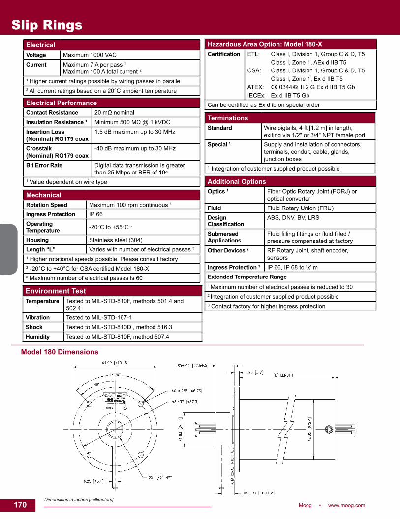
170 Moog • www.moog.com
Slip Rings
Model 180 Dimensions
Dimensions in inches [millimeters]
ElectricalVoltage Maximum 1000 VACCurrent Maximum 7 A per pass 1
Maximum 100 A total current 2
1 Higher current ratings possible by wiring passes in parallel2 All current ratings based on a 20°C ambient temperature
MechanicalRotation Speed Maximum 100 rpm continuous 1
Ingress Protection IP 66Operating Temperature -20°C to +55°C 2
Housing Stainless steel (304)Length “L” Varies with number of electrical passes 3
1 Higher rotational speeds possible. Please consult factory2 -20°Cto+40°CforCSAcertifiedModel180-X3 Maximum number of electrical passes is 60
Additional OptionsOptics 1 Fiber Optic Rotary Joint (FORJ) or
optical converterFluid Fluid Rotary Union (FRU)Design Classification
ABS, DNV, BV, LRS
Submersed Applications
Fluidfillingfittingsorfluidfilled/ pressure compensated at factory
Other Devices 2 RF Rotary Joint, shaft encoder, sensors
Ingress Protection 3 IP 66, IP 68 to ‘x’ mExtended Temperature Range1 Maximum number of electrical passes is reduced to 302 Integration of customer supplied product possible3 Contact factory for higher ingress protection
Electrical PerformanceContact Resistance 20mΩnominalInsulation Resistance 1 Minimum500MΩ@1kVDCInsertion Loss (Nominal) RG179 coax
1.5 dB maximum up to 30 MHz
Crosstalk (Nominal) RG179 coax
-40 dB maximum up to 30 MHz
Bit Error Rate Digital data transmission is greater than 25 Mbps at BER of 10-9
1 Value dependent on wire type
TerminationsStandard Wire pigtails, 4 ft [1.2 m] in length,
exiting via 1/2" or 3/4" NPT female portSpecial 1 Supply and installation of connectors,
terminals, conduit, cable, glands, junctionboxes
1 Integration of customer supplied product possible
Hazardous Area Option: Model 180-XCertification ETL: Class I, Division 1, Group C & D, T5
Class I, Zone 1, AEx d IIB T5 CSA: Class I, Division 1, Group C & D, T5 Class I, Zone 1, Ex d IIB T5 ATEX: 0344 II 2 G Ex d IIB T5 Gb IECEx: Ex d IIB T5 Gb
CanbecertifiedasExdibonspecialorder
Environment TestTemperature Tested to MIL-STD-810F, methods 501.4 and
502.4Vibration Tested to MIL-STD-167-1Shock Tested to MIL-STD-810D , method 516.3Humidity Tested to MIL-STD-810F, method 507.4

171Moog • www.moog.com 171
FPSO Swivels
250 FPSO swivel
DescriptionWe design, manufacture and deliver unique FPSO swivels to meet the demanding requirements of offshore operators worldwide. Typically comprised of Electrical Slip Rings, Hydraulic Utility Swivels and Fiber Optic Rotary Joints, swivels are used in a variety of Floating Production, Storage and Offloading (FPSO) Systems including buoys, turret moorings and offshore loading towers. Our FPSO swivels permit the continuousdeliveryofelectricalpowerandsignals,hydraulicfluids,andfiberopticsignals,withunlimitedfreedomofthevesseltoweathervaneabout its mooring point. All FPSO swivels are approved by a marine authorityandarecertifiedforuseinhazardouslocations.
Features• Stainless steel construction standard• Large hollow bores• Flameproof or purged / pressurized• Integraljunctionboxesavailable• Fluidsforhydrauliccontrolandchemicalinjection• Singleandmultimodefiber• Wide variety of cable entry methods
Benefits• Each unit designed, manufactured, and tested in accordance with
the highest quality standards• Optical,electricalandfluidinoneassembly• ModeledwithleadingCADsoftwareandfilesshared
with customers• Fully inspected and tested before shipment• On-site installation support• Complete document package provided

172 Moog • www.moog.com
295-X FPSO swivel
DescriptionThe 295-X is a standardized electrical / optical slip ring designed for the offshore oil industry. This design is type certified for hazardous area environments allowing for shorter design customization and assembly time. Available in sizes ranging to a maximum overall length of approximately 140 inches (3.5 m) and overall diameter of 12 inches (300 mm), this model meets the needs to transfer utility power, electrical and optical signals on a variety of offshore swivel applications.
Features• 316 stainless steel housing available for corrosion resistance• HazardousareacertifiedinaccordancewithEuropean
Community ATEX directive 94 / 9 / EC• Standardized design can accommodate variety of cable entry
methods
Benefits• Each unit is designed, manufactured, and tested in accordance with
the highest quality standards• Integrationwithfiberopticrotaryjointsandfluidrotaryunionstopro-
vide a complete rotating interface solution • Design customization to meet both customer and marine authority specifications
1 m
Typical Applications
• CALM buoy• Submerged turret loading vessel• FPSO swivel stacks
FPSO Swivels

173Moog • www.moog.com 173
FPSO Swivels
FO295-X Dimensions
1. Dimensions in inches [mm]2. Dimension ‘L’ varies with the number of passes3. Dimension ‘Ø D’ maximum 12.75 [323.8]4. Customer interface and drive arrangement may vary.
Electrical295-X is rated in accordance with customer requirementsVoltage Maximum 5000 VACCurrent Designedtocustomerspecifications
MechanicalRotation Speed Maximum 50 rpm continuous 1
Protection Class IP 66Operating Temperature -20 °C to + 55 °CHousing Stainless steel (304)Length “L” Varies with number of electrical
passes 1 Higher rotational speeds possible. Please consult factory.
Additional OptionsFiber Optics Fiber Optic Rotary Joint (FORJ) or
Optical ConverterFluid Fluid Rotary Union (FRU)Design Certification ABS, DNV, BV, LRSSubmersed Applications
Fluidfillingfittingsorfluidfilled/pressurecompensated at factory
Other Devices1 RF Rotary Joint, Shaft Encoder, Sensors, Heat Trace Cable
Ingress Protection IP 68Extended Temperature Range1 Integration of customer supplied product possible
Electrical Power Performance295-X power performance is design in accordance with customerspecificationsandCertifyingAuthorityrequirementsFlashover Voltage Typically 4x Vrated
Insulation Resistance This will vary depending on design specifications.Contactfactoryforfurther details.Short Circuit Rating
Electrical Signal PerformanceContact Resistance 20mΩnominalInsulation Resistance 1 Minimum500MΩ@1kVDCInsertion Loss 2(Nominal) RG59 coax 1.5 dB maximum up to 30 MHz
Crosstalk 2
(Nominal) RG59 coax -15 dB maximum up to 30 MHz
1 Value dependent on wire type. 2Performancedependsonconfigurationofsignalcircuits.
TerminationsStandard Integral armoured cables on the geo
stationary side, increased safety junctionboxesontherotatingside
Special 1 Supply and installation of connectors, terminals, conduit, cable, glands, junctionboxes
1 Integration of customer supplied product possible
Hazardous Area Option: 295-XKEMA Designation for ATEX certified unit.
ATEX II 2 G Ex d IIB T5

174 Moog • www.moog.com
Multiplexers and Media Converters
Multiplexers and Media ConvertersRuggedized to function in harsh marine environments DescriptionToexploitthefullbandwidthoffiber,multiplexingcombinesmanysignalsof various types — video, serial data, network data, control lines — into one high speed optical signal. Multiplexers that combine a number of electrical signals are typically called time division multiplexers (TDM), as each input signal is assigned a time slot in the outgoing data stream. Moog has a wide range of TDM options that allow multiple electrical channelstobemultiplexedontooneormoreopticalfibers.
Multiplexersthatcombineanumberofopticalsignalsontoonefiberarealso available. These multiplexers use wavelength-division multiplexing (WDM) to transmit signals at multiple wavelengths of light on the same opticalfiber.Opticalsplittersandswitchesmaybeaddedtoprovideredundancyinthefiberlinks.
Both multiplexing techniques can be used separately or together to simplify optical transmission systems and reduce cost, improve reliability, reduce weight and improve performance. Multiplexed systems also simplify system upgrades since numbers of channels and channel bandwidth is a function of the electronics rather than the transmission line or components. Moog multiplexers accommodate the ever-increasing data rates needed for digital video and industrial data protocols, as well as high speed networks such as Ethernet. Features • Support for broadcast quality video in composite (NTSC / PAL), Y / C (S-video), RGB, and YPrPb formats • Support for digital video formats including SDI and HD-SDI• Support for many serial data, network, and bus protocols, including TTL, RS-232, RS-485 / 422, Ethernet, CANBus, ARCNET, Profibus,USB,ECL/PECL,andvarioussonars• Support for many analog signal formats, including audio, hydrophones, and various sensors• Modularsystemforeasyreconfigurationwithupto32video channels and 256 data channels per system• Low latency data transmission for time-critical control, e.g. force-feedback robotic manipulators• Embedded diagnostics including LED indicators and PC based diagnostics via serial, Ethernet or Modbus interfaces• Pressure tolerant electronics and optics available
Typical Applications
Industrial• Remotely Operated Vehicles (ROVs)• Pipe inspection robots • Video security systems• Tether management systems• FPSO communications Process controlMilitary• Bomb disposal robots• Tactical networks• Defense systems• Armored vehicle turrets• Electro-optic sensors

175Moog • www.moog.com 175
Multiplexers and Media Converters
Product Summary
Model Number
Description Video Serial Data (RS-232 / 422 / 485)
Ethernet Diagnostics
Model 903 Family (Rack Mounted 3U Eurocard Form Factor)903 Video + Data Multiplexer 8 x NTSC / PAL 64 3 x 10 / 100 M LED, RS-232, Ethernet*
903-HD Compact Video + Data Multiplexer 8 x NTSC / PAL 16 - LED, RS-232, Ethernet*
EIB-10 / 100 3-Port Ethernet Media Converter - - 3 x 10 / 100 M LED
ECL-02 Dual ECL (Sonar) Media Converter - 2 x ECL / PECL, 30 - 150 Mbps
- LED, Ethernet*
HDSDI-MC HD-SDI Media Converter 1 x HD-SDI - - LED
GBES-MC 4-Port Gigabit Ethernet Media Converter - - 4 x 10 / 100 / 1000 M LED
903-GEM 4-Channel Gigabit Ethernet Multiplexer (Switchless)
- 0 - 48** 4 x 10 / 100 / 1000 M LED, Ethernet*
Model 907 Family (PC / 104 Form Factor)907-E 2-Channel Video, Ethernet and
Serial Data Multiplexer2 x NTSC / PAL 4 - 52** 1 x 10 / 100 / 1000 M LED, Ethernet*
907-R / C 3-Channel Video + Data Multiplexer 3 x NTSC / PAL 6 - 48** 3 x 10 / 100 M LED
907 PLUS 4-Channel Video + Data Multiplexer 4 x NTSC / PAL 6 - 54** 3 x 10 / 100 M LED, Ethernet*
907-GEM 4-Channel Gigabit Ethernet Multiplexer (Switchless)
- 0 - 48** 4 x 10 / 100 / 1000 M LED, Ethernet*
907V 6-Channel Video Multiplexer 6 x NTSC / PAL 0 - 48** 3 x 10 / 100 M LED, Ethernet*
907-HDM2 2-Channel HD-SDI / Data Mux 2 x HD-SDI 4 - 20** - LED, Ethernet*
907-ECL ECL (Sonar) Media Converter - 1 x ECL / PECL, 30 - 150 Mbps
- LED, Ethernet*
907-HDV HD-SDI Media Converter 1 x HD-SDI - - LED, Ethernet*
907-GBE Gigabit Ethernet Media Converter - - 1 x 10 / 100 / 1000 M LED, Ethernet*
907-GBES 4-Port Gigabit Media Switch - - 4 x 10 / 100 / 1000 M LED, Ethernet*
907-DIAG-E Ethernet Diagnostic Card (For Access to 907 Cards)
- - 1 x 10 / 100 M LED, Ethernet*
907-FLEX Flexible Quad Media Converter Card 2 - 4 x 3 G / HD-SDI or
2 - 4 x NTSC
- 1-2 x 10 / 100 / 1000 M LED, Ethernet*
Model 914 Family (Credit Card Sized Form Factor)914-R / C 1-Channel Video + Data Multiplexer 1 x NTSC / PAL 4 - 6** 2 x 10 / 100 M Ethernet
ChannelsLED
914-MCS 2-Port Ethernet Media Converter - - 2 x 10 / 100 M LED
914-GBE Gigabit Ethernet Media Converter - - 1 x 10 / 100 / 1000 M LED
914-HDV HD-SDI Media Converter 1 x HD-SDI - - LED
Multiplexer Diagnostics SoftwareThis software is available to monitor multiplexer performance from the console end of a system. Optical power, voltage levels, and system status can be monitored for both uplink and downlink communications over standard Ethernet, Modbus, and Modbus TCP / IP.
Custom SolutionsOur advanced CAD systems enable rapid development of new interfaces and packages to suit diverse applications. With more than 100 different types of printed circuit boards
developedinthelastfiveyears,wehaveestablishedanexperiencedteamofdesignerswithexpertiseinsoftware,firmware,high-speeddigitalandanaloginterfaces,andfiberoptics.Existingcustomsystemssupport high shock and vibration environments, EMC, and long life requirements of more than 200,000 hours and long data links with up to200kmoffiber.Moreover,ourexperiencewiththedetaileddesignoffiberoptictransmittersandreceiversprovidesalevelofoptimizationandperformance that is not achievable with typical commercial devices.
Contact Moog for custom mulitplexer solutions for subsea controls, defense and other specialized rugged applications.
The above list is a small sample of available cards. For full product details please see product data sheets or multiplexer catalog found on the website at: www.moog.com.*Ethernet diagnostics via FMB-X for 903 and via 907-DIAG-E card for 907. **Minimum serial channels are included on board; maximum channels require expansion cards.

176 Moog • www.moog.com
Fluid Rotary Unions (FRU)
Moog Components Group • www.moog.com/components176

177Moog • www.moog.com 177
Fluid Rotary Unions (FRU)
Fluid Rotary UnionsDescriptionInitially toserve indiver life-supportunmbilical systems,fluid rotaryunionshavebeendiversifiedtoincludeabroadrangeofapplications.
Ourfluidrotaryunionsarecurrentlyusedaroundtheworldtoensurereliable transmission of life support, process, power and control fluids.Currently,fluidrotaryunionsratedforpressuresupto15,000psi (1000 bar) are available. Seals are selected based on chemical compatibility, design pressure, design temperature, required service life and acceptable leakage rate. Leak collection can be supplied when required for environmental or personnel safety. Fluid rotary unions can becombinedwithourelectricalsliprings,motor,resolversandfiberopticrotaryjoints.
Features• Customizedmountinganddriveconfigurations• Customized materials to satisfy weight, chemical compatibility and
other requirements• Customizedportconfigurations• Hardcoating,standardonhighpressurefluidrotaryunions,canbe
selected for improved abrasion resistance and extended seal life
• Leakage detection and collection ports (drain to tank)• Optional hollow bore
Typical Applications
• Marine and life support systems such as saturation diving
• Training centrifuges for pilots and astronauts
• Industrial indexing tablets• Chemicalinjectionsystems• FPSO hydraulic power and
control systems• Semiconductor clean room robotics

178 Moog • www.moog.com
Fluid Rotary Unions (FRU)
SpecificationsPart # Hollow Bore Passes
Qty SizePressure Speed (rpm) Sample
ApplicationsMounting
FlangeComments
70 Optional ≤11≤1inch
≤3000psi≤200bar
≤10 Diving Industrial Scientific
Standard 1, 2, 3, 4, 12, 13
134 N/A 1 ≤1inch
≤4000psi ≤275bar
≤5 Seismic N/A See Note 1, 2, 3, 5, 12
136 Optional ≤5 ≤1/2inch
≥5000psi ≥345bar
≤1000 Scientific Military
Cooling Systems
Optional See Note 1, 2, 3, 6, 12, 13
255 Optional Multiple 1/4 - 1-1/2 inch
≤5000psi ≤345bar
≤50 Industrial Military
Optional See Note 1, 2, 3, 7, 12, 13
248 Optional Multiple ≤1/4inch
≤1000psi ≤70bar
≤100 Scientific Industrial
Optional See Note 1, 2, 3, 8, 12, 13
271 Optional ≤5 ≤3/4inch
≤1000psi ≤70bar
≤25 Industrial Military Scientific
Optional See Note 1, 2, 3, 9, 12, 13
278 Standard 2 ≤1/2inch
≤150psi ≤10bar
≤150 Military Cooling Systems
Optional See Note 1, 2, 3, 12, 13
284 Standard Multiple 1/4 - 2-1/2 inch
≤15000psi ≤1000bar
≤5 FPSO and SPM Hydraulic Controls
Standard See Note 1, 2, 3, 10, 11,
12, 13290 Standard ≤2
≤3inch≤200psi ≤15bar
≤5 FPSO and SPM Fire Suppression
Standard See Note 1, 2, 3, 10, 11,
12, 13301 N/A 1
1/2 inch≤145psi≤10bar
≤250 Industrial Standard 1, 2
306 1-1/2 inch 11/2 inch
≤145psi≤10bar
≤100 Industrial Optional 1, 2
307 Standard 21/8 inch
≤145psi≤10bar
≤200 Industrial Optional 1, 2, 3
Dimensional drawings available upon request. Notes: 1. Values are representative of a typical range only and do not indicate limits.2. Typical uses listed. Units suitable for other applications.3. All models are available combined with ESR and FORJ.4. Availableinanumberofstdconfigurations.Utilizesastackedhousingdesign.5. Generally a COTS pipe swivel combined with an ESR.6. May require auxiliary cooling.7. Utilizes a single piece housing design.8. Basically a smaller version of the FO255.9. Includes all FRU that are fully integrated with either ESR and FORJ.10. Leak measurement and collection ports std.11. FPSO-floatingproductionandoffloading.SPM-Singlepointmooring.12. Material selection based on application and includes chemical compatibility, design pressure, design temperature, required service life. 13. Hollow bore may be on axis or a parallel axis wire path as required for the application.
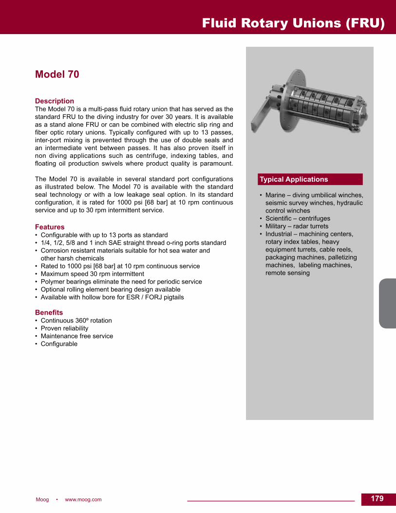
179Moog • www.moog.com 179
Model 70
DescriptionTheModel70isamulti-passfluidrotaryunionthathasservedasthestandard FRU to the diving industry for over 30 years. It is available as a stand alone FRU or can be combined with electric slip ring and fiberoptic rotaryunions.Typicallyconfiguredwithup to13passes,inter-port mixing is prevented through the use of double seals and an intermediate vent between passes. It has also proven itself in non diving applications such as centrifuge, indexing tables, and floating oil production swivelswhere product quality is paramount. TheModel 70 is available in several standard port configurationsas illustrated below. The Model 70 is available with the standard seal technology or with a low leakage seal option. In its standard configuration, it is rated for1000psi [68bar]at10 rpmcontinuousservice and up to 30 rpm intermittent service.
Features • Configurablewithupto13portsasstandard • 1/4, 1/2, 5/8 and 1 inch SAE straight thread o-ring ports standard • Corrosion resistant materials suitable for hot sea water and other harsh chemicals • Rated to 1000 psi [68 bar] at 10 rpm continuous service • Maximum speed 30 rpm intermittent • Polymer bearings eliminate the need for periodic service • Optional rolling element bearing design available • Available with hollow bore for ESR / FORJ pigtails Benefits • Continuous 360º rotation • Proven reliability • Maintenance free service • Configurable
Typical Applications
• Marine – diving umbilical winches, seismic survey winches, hydraulic control winches
• Scientific–centrifuges• Military – radar turrets• Industrial – machining centers,
rotary index tables, heavy equipment turrets, cable reels, packaging machines, palletizing machines, labeling machines, remote sensing
Fluid Rotary Unions (FRU)

180 Moog • www.moog.com
Model 70 SpecificationsAmbient Temperature Gases Liquids
-40ºC to +60ºC -40ºC to +100ºC 0ºC to +60ºC
Pressure 1000 psiRotational Speed 10 rpm continuous
30 rpm intermittentTorque Approx. 80 lb-ft [110 N-m]Shock / Vibration Mil-Std-167 (ships)
Weight DependentonconfigurationEnvironmental Marine, open deckLeakage Std. Seal 50 std. mL / min N2gaspersealrotating@1000psimax
Typically less than 10 std. mL / min N2gaspersealrotating@1000psiLow Leak Seal 2 std. mL / min N2gaspersealrotating@1000psimax
Typically less than 0.05 std. mL / min N2gaspersealrotating@1000psiNominal Port Size 1/4 inch 1/2 inch 5/8 inch 1 inch
SAE straight thread O-ring thread size 7/16-20 UNF 3/4-16 UNF 7/8-14 UNF (passage size suitable for 3/4” nominal, 1-1/16-12 UN adapter) 1-5/16-12 UN
Model 70 Dimensions
Dimensions in inches [millimeters]
Fluid Rotary Unions (FRU)
Please note that operational life of the unit is dependent upon rotational speed, environment and temperature. Flexible conduit should be used to couple to the rotating component. The torque arm must be loose coupled.
Sample Configurations*Port Size Number of Ports
1” 0 0 1 0 0
5/8” 1 3 1 5 3
1/2” 4 1 4 0 3
1/4” 5 6 5 5 7
DIM ‘A’ 4.50 [114] 4.50 [114] 4.50 [114] 4.50 [114] 5.00 [127]
DIM ‘B’ 4.14 [105] 4.03 [102] 4.53 [115] 4.15 [105] 4.55 [115]
DIM ‘C’ 14.50 [368] 14.88 [378] 16.50 [419] 15.77 [400] 18.39 [467]
DIM ‘D’ 6.75 [171.5] 6.75 [171.5] 6.75 [171.5] 6.75 [171.5] 7.25 [184.2]
*Note: There are other configurations available, please contact factory for more information.

181Moog • www.moog.com 181
Model 301
DescriptionThe Model 301 is a single pass fluid rotary union that can beoperated as a stand alone FRU. Its design has been optimized to allow an AC4598 / AC6200 or can be combined with a Moog electrical slip ring (ESR) to be mounted directly on the Model 301 body, simplifying the integration and mounting arrangement. The Model 301 utilizes sealed-for-life rolling element bearings to provide long trouble free service. Filled PTFE based seals run on a hardened surface to provide long service life, minimizing frictional heat generation and operational torque. This unit has been tested in excess of 80 million revolutionswithout a failure.TheBSPP ports andmounting flangeallowconvenientfixturingagainstanO-ringsealedshaftorseparatethreaded conduit. Features• 1-1/2 inch body O.D. to mount AC4598 / AC6200 • 1 pass with 1/2 inch BSPP ports • Rated to 145 psi [10 bar] at 250 rpm continuous service • Maximum working pressure 180 psi [12.5 bar] • Maximum recommended speed 2000 rpm (intermittent or withsufficientmediumflowtocoolassembly) • Stainless steel version available• Longer housing available to accomodate slip ring length Benefits• Continuous 360º rotation • FRU transfers air, oil, other non-corrosive medium • Provides long maintenance free service • Convenient mounting of FRU / ESR combination• Tested in excess of 80 million revolutions
Typical Applications
• Industrial – machining centers, rotary index tables, heavy equipment turrets, cable reels, packaging machines, palletizing machines, labeling machines, remote sensing
Fluid Rotary Unions (FRU)
REVISED 02/15

182 Moog • www.moog.com
Fluid Rotary Unions (FRU)
Shown with optional AC4598 installed (see Model 813 data sheet for more details).
Model 301 Dimensions
Model 301 Specifications OptionsOperating Temperature -40º to 60º C with optional ESR
-40º to 80º C without ESR installed• Stainless steel construction • Longer housing available to accomodate slip ring lengthPasses Quantity Size 1x 1/2 inch BSPP
Pressure and Speed 145psi[10bar]@250rpmMaximum Pressure 180 psi [12.5 bar]Maximum Speed 2000rpm(intermittentorwithsufficientcoolingfrommedium)Maximum Torque (Estimated) 2.5 lb-in [282 N-mm]Environmental IP65option(jettedwateranddustsealoption)
Please note that operational life of the unit is dependent upon rotational speed, environment and temperature. Flexible conduit should be used on the torque are end to avoid side loading, which can shorten operational life.
Dimensions in inches [millimeters]
REVISED 02/15

183Moog • www.moog.com 183
Model 306
DescriptionAfluidrotaryunion(FRU)functionsasarotaryinterfaceforfluidcarryingconduit between stationaryand rotatingequipment.The fluidbeingconveyedcanbeliquid,gas,orvacuum.Afluidrotaryunionisalsocalleda rotaryunion, fluidswivel,utility swivel,hydraulic swivel,hydraulicutilityswivel,orrotaryjoint.Unlikeflexibleconduit,afluidrotaryunionallowscontinuousunrestrainedrotationofmovablejointsinmachinery. The Model 306 is a single pass fluid rotary union. It can be operated as a stand alone FRU. Its design has been optimized to allow easy integration with an AC4598 / AC6200 electric slip ring (ESR). The 1-1/2 inch hollow bore and ESR pigtail channels allow concentric shaft mounting or optional flange mounting with an ESR mounted directly to it using the optional adapter. The Model 306 utilizes sealed-for-life rolling element bearings to provide long trouble free service. Filled PTFE based seals run on a hardened surface to provide long service life, minimizing frictional heat generation and operational torque.
Features • 1-1/2 inch through bore • Pigtail channels integral to shaft • 1 pass with 1/2 inch BSPP ports • Rated to 145 psi [10 bar] at 100 rpm continuous service • Maximum working pressure 4000 psi [275 bar] • Maximum recommended speed 450 rpm (intermittent or with sufficientmediumflowtocoolassembly) • 1/2-13 UNC-2B thread for torque arm • Optional ESR drive pin matches AC4598 / AC6200 torque arm allowing a single anti rotation interface • Optional ESR mount for AC4598 / AC6200 leaves reduced bore clear • Stainless steel version available Benefits • Continuous 360º rotation • FRU transfers air, oil, other non-corrosive medium • Provides long maintenance free service • Convenient mounting of FRU / ESR combination
Typical Applications
• Industrial machinery – machining centers, rotary index tables, heavy equipment turrets, cable reels, packaging machines, palletizing machines, labeling machines, remote sensing
Fluid Rotary Unions (FRU)
REVISED 02/15

184 Moog • www.moog.com
Model 306 Specifications OptionsOperating Temperature -40ºC to +100ºC • Stainless steel construction
• Torque armPasses Quantity Size 1x 1/2 inch BSPPPressure and Speed 145psi[10bar]@100rpmand60ºC
Maximum Pressure 4000 psi [275 bar]Maximum Speed 450rpm(intermittentorwithsufficientcoolingfrommedium)Maximum Torque (Estimated) 6 lb-ft [8 N-m]Weight 25 lb [11 kg]Environmental IP42
Model 306 Dimensions
Fluid Rotary Unions (FRU)
Please note that operational life of the unit is dependent upon rotational speed, environment and temperature. Flexible conduit should be used on the torque are end to avoid side loading, which can shorten operational life.
Dimensions in inches [millimeters]

185Moog • www.moog.com 185
Integrated Mechanisms
Moog Components Group • www.moog.com/components 185

186 Moog • www.moog.com
Integrated Mechanismseach item produced.
When a single manufacturer of these magnetic and electromechanical components has this responsibility, these issues can be offset with optimized processing of the discrete componentsensuringafinalassemblyoptimized for performance, electrically and mechanically aligned and fully tested.
System design can often be optimized when a single manufacturer can conduct trade-off studies of the various components. Within a given mechanical envelop, space can be optimized, total component count reduced and structures sculpted with an end result of increased MTBF and reduced end-item weight.
Resource OptimizationThis approach ensures system engineers are focused on the system, not its components. By optimizing and focusing engineering resources, program risks are minimized, schedules maintained and costs reduced.
Additionally, overhead costs are reduced by eliminating the manpower of soliciting multiple contractors and resulting contract administration, multiple incoming inspections of discreet components and the resulting expenses of pulling and distributing component kits. Additional program costs are saved by eliminating the need of holding multiple design reviews at different locations, multiple qualificationtestsandthereviewandapproval of their related documents.
AccountabilityYou are assured that all system components are integrated properly and a fully tested end-item assembly is delivered. And, in the rare case that a technical problem should occur, you know exactly who to call for immediate help.
Example of Integrated Motion TechnologyRadar Pedestal
Moog’s unique product offering of motion technology (slip rings, motors, resolvers, drives and actuators) and fiberopticproductsprovidesthecapitalassets and engineering capabilities to design, manufacture and integrate these discrete products into an integrated gimbaled mechanism. In today’s business environment where many corporate strategies are to focus on core competencies, let Moog take the design and integration of these discrete components into fully functional and tested subassemblies that are ready for installation into the end-item assembly. Should your strategy be to outsource these assemblies on a build-to-print basis, we are ready to apply our resources so you can achieve those goals too. Our integrated assemblies range from simple combinations of slip rings and resolvers to sophisticated electro-mechanical assemblies including the motor, drive electronics, fiber opticrotary joints,hydraulicandpneumaticswivelsandRF rotary joints.Wealsooffer and provide fully integrated servo and utility actuators complete with precision gearing, clutches, brakes and closed-loop control electronics.
Our business strategy is simple, let Moog focus on what we do best so our customer can focus on what they do best. This strategy provides our customers with many measurable benefits.
Optimized systems that operate at peak performanceTolerance stack up can rob magnetic and electromechanical designs of their intended performance capabilities. Maintaining air gap and mechanical tolerances are critical in precision electromechanical mechanisms. Even though the discrete components fall within specified tolerances, tolerancestack up may result in system performance problems. The end result is costly system redesign, component matching or assembly shimming for

187Moog • www.moog.com 187
With all marine, military and aerospace programs, a heritage of program success is essential. Moog has successfully provided integrated mechanisms to many mission critical programs including the following:
Moog looks forward to applying our design and manufacturing resources to your program’s integrated assembly needs.
Integrated Mechanisms
Example of Integrated Motion Technology
Marine MarketPlatform Integrated Assembly FloatingProductionStorageandOffloadingVessel(FPSO)
Slip ring, FORJ, HUS and OEO converter Cablesandjunctionboxes
Remotely Operated Vehicles Multiplexer, slip ring and FORJSeismic Streamer Slip ring and FRU
Slip ring and FORJSingle Point Mooring System CALM Buoys Slip ring, FORJ and FRUMilitary MarketPlatform Integrated Assembly Helicopter Slipring,resolverandRFrotaryjointHelicopter Twist cap and resolverRotorcraft Slip ring, resolver and monopole sensorArmored Vehicle Slip ring, resolver, R-to-D network, hydraulic and pneumatic
swivel, and power distributionArmored Vehicle Slip ring, encoder and pneumatic swivelRadar Slip ring, motor, resolver, motor control and drive electronics,
and 2-channel FORJRadar Slip ring, digital resolver, motor and bull-gearRadar Servo actuator, motor and drive electronicsRadar Slip ring, FORJ and FRUNaval Towed Arrays Slip ring, FORJ and FRUSpace MarketPlatform Integrated AssemblySolar Array Drive Slip ring, motor, harmonic drive and potentiometerSolar Array Drive Slip ring, motor and resolverSatellite Mechanism Motor, ball screw and balanced weightIndustrial MarketPlatform Integrated AssemblyRotary Piston Machining Centre Mux, slip ring, FORJ and FRUCoal Stacker, Reclaimer Slip ring, FORJ, FRU and encoder

188 Moog • www.moog.com
Technical Information
Moog • www.moog.com188

189Moog • www.moog.com 189
Technical Information
IntroductionAs the analog world gives way to the digital in more and more applications, design engineers are faced with replacing traditional analog components with their digital equivalents. Nowhere is this more evident than in the electro-mechanical world. Analog resolvers are being replaced by digital encoders and digital drive circuitry has become commonplace for motor control. When part of the system has to rotate, and a rotary connection for power and digital data is required, what does the designer do? Can the traditional slip ring with its sliding electrical contactshandlethejob?
The ProblemSlip rings were originally designed to carry AC and DC power from a rotating platform to a stationary structure, or vice versa. Many applications also required, and still require, the transmission of relatively low bandwidth analog and digital control signals. In this environment, the traditional slip ring performs extremely well. Modern control systems now also require the transmission of high bandwidth analog and digital signals through the slip rings. Typical examples are analog and digital video signals. Until recently, bandwidths measured in the tens of megahertz were generally adequate. Today, and in the future, bandwidths will be required that are orders of magnitudes higher.
Basic Slip Ring ConfigurationA basic slip ring, shown schematically in Figure 1, is composed of four elements, or components:
• A ring assembly that provides one or more circuit paths. Each ring is electrically conductive and provides a circuit path over a full 360 degrees of rotation of the ring assembly.
• Brushes provide electrical contact between the rotating (usually the ring) and the stationary parts of the assembly. The brushes ride on the ring, and are mounted in a brush block assembly, usually on the stationary structure.
• Input and output leads that connect the ring and brushes to the outside world.
• Connectors that connect to the slip ring assembly wiring. Connectors are optional,andareoftenspecifiedbythecustomer.
Factors Affecting Slip Ring PerformanceThe following factors will determine the data rate that can be transmitted through a slip ring:
• The frequency response, or insertion loss, of the rings and brushes.
• The impedance, as a function of frequency, of the assembly.
• The differential time delay, as a function of frequency, through the device.
• Crosstalk between circuits.• Frequency response of the leads and connectors.
The primary factor is frequency response, or bandwidth. Digital data streams will begin to suffererrorsfrominsufficientbandwidthwhenthe digital signal is attenuated, or distorted, to such an extent that the digital receivers cannot properly recognize the received signal. A digital signal is composed of a fundamental frequency at the basic signaling rate, as well as the odd harmonics of the fundamental. The required bandwidth of the slip ring may be several times the data rate.
For example, a 1 MHZ square wave may require a bandwidth of 5 or 7 MHz (5th and 7th harmonics). As the data rate is increased, eventually the harmonics is matched to the external system input and output impedances. Using transmission line theory, the designer will vary ring geometry, spacing, and dielectric material, to obtain the needed impedance. Often a ring and brush impedance of 70 to 150 ohms is obtainable, which should be well suited for many of today’s digital systems. As a rule of thumb, a smaller diameter ring will result in a higher data rate. For very high data rates and / or large ring diameters, multiple taps and multiple brushes are often used to minimize signal path lengths.
For optimal performance, high frequency digital signals should be driven differentially, and connected to the slip ring using twisted pair, shielded cable such as CAT5 or CAT5e. This same wiring, including the shield, should
Do Slip Rings Fit in the Digital World?
be continued through the slip ring. Ideally, the internal slip ring wiring would also be twisted pair shielded cable, however, this may not always be possible due to physical constraints. Connectors, if used, must also be designed, or chosen, to have an impedance and frequency response consistent with system requirements.
Crosstalk between sensitive circuits will also be minimized by proper lead routing and shielding. Sensitive circuits (victims) should be routed within the slip ring as far away from noisy circuits (sources) as possible. Also, all unused circuits should be terminated in the characteristic impedance of the cables used.
Specifying a High Performance Slip RingThis article has attempted to make users aware of factors that determine slip ring performance, and of the limitations imposed by the total system in which the slip ring must operate. It is no longer adequate to simply request a device “that will transmit 50 mbs.” The best solution is obtained when the entire system is known and understood, and usually requires a compromise between performance, size, weight, number of circuits, external factors, and cost.
Thefollowingparametersshouldbespecifiedtoassuresatisfactoryoperationinaspecificapplication:
• Data bus used to transmit data, i.e. Profibus,Ethernet,Firewire• Cable type used to connect to the slip ring• Maximum cable length between transmitter and receiver• Maximum data rate• Maximum error rate that can be tolerated

190 Moog • www.moog.com
Technical Information• Maximum size, i.e. diameter and length• Number of circuits and their ratings, i.e. voltage, current • Maximum operating speed of rotation• Operating environment
Moog has thousands of slip ring designs, including many standard “off the shelf” designs. Our engineering staff is available to modify an existing design or to provide a completely new design, if required. However, customers are encouraged to evaluate a standard design before requesting modificationsthatmaynotbeneeded.
We have tested many of our standard designs for high data rate performance. Devices with through bores of up to six inches have been tested. Testing has included insertion loss, frequency response, bit error rates, differential time delay, and impedance over frequency.Insomecaseswehaveidentified,and implemented, design modifications tosignificantly improve performance. As ageneral statement, all devices that have been tested will support digital data rates of at least 50mbs.Thisverifiesthatourstandardunitswill operate successfully in a wide variety of
standard data systems in use world–wide. These include, but are not limited to: Device Net, CAN Open, Profibus, and Ethernet10Base T. Additionally, several models tested are suitable for Ethernet 100Base T, and Firewire at 400 mbs.
For the most demanding applications, we have integrated single channel and multiple channel fiber optic rotary joints (FORJs)into our standard slip ring assemblies. The FORJ is used to carry the very high data rate signals, or those circuits requiring very low cross talk or high noise immunity, while conventional slip ring technology is used for transmitting power and other control signals. We can also provide the hardware to perform the electrical- to optical- back to electrical conversion.
ApplicationsIndustrial and Commercial• Semiconductor equipment• Industrial machinery• Robotics• Medical equipment• Packaging machines• Cable reels• Laboratory equipment• CCTV camera mounts• Lighting• Rotary index tables• Rate tables• Medical CT scanners• Amusement rides• Flight simulation
Aerospace and Military• Inertial navigation systems• Missile weapon systems• Satellite assemblies• Unmanned aerial vehicles• Airborne camera platforms• Shipboard communication systems• Radar• Tanks• Light armored vehicles• Helicopters• Aircraft
Marine• Remote operated vehicles (ROV)• Seismic surveying• Oceanographic winches• Subsea communications and control• Floating production, storage and offshore loading (FPSO)• Diving• Marine instrumentation• Downhole / wirelogging and drilling
Slip Ring Fundamentals
A standard slip ring has fourelements, or components:
• A ring assembly provides one or more circuit paths. Each ring is electrically conductive and provides a circuit path over a full 360° of rotation of the ring assembly.
• Brushes provide electrical contact between the rotating (usually the ring) and the stationary parts of the assembly. The brushes ride on the ring, and are mounted in a brush block assembly, usually on the stationary structure.
• Input and output leads connect the ring and brushes to the outside world.
• Connectors link to the slip ring assembly wiring. They are optional andoftenspecifiedbythecustomer.
Moog fiber brush contact technology wasinitially developed to solve a critical problem in military / aerospace applications. With many years of successful performance in highlycriticalslipringapplications,thefiberbrush technology is available in commercial products as well.
Fiber Brush Technology For Commercial / Industrial ApplicationsFor many years the traditional design for rotary contact slip rings used either a lubricated monofilament brush or a self-lubricating composite brush. While these traditional approaches have proven to be successful through testing and fieldexperience, improved performance is always desirable. To that end, we developed the fiberbrushtechnology.Achartcomparingtheadvantages of different contact technologies is shown on page 161.
Today’s industrial / commercial equipment slip ring requirements are becoming more and more demanding. High operational speeds, long life, no maintenance, and data transfer capability, are the general expectations in slip ring performance. Taking advantage of the developments done in our Advanced Materials Research and Development Department, we have transferred the fiber brush technology to cost effective
commercially available products to address today’s critical applications.
Military / aerospace applications require slip rings that provide minimal debris generation, low electrical noise, both high and low current transmission capabilities, low outgassing and a long operational life. They must also operate flawlessly inawideoperatingtemperaturerange, and at a variety of brush ring surface speeds, as well as in air or vacuum conditions.

191Moog • www.moog.com 191
Fiber Brush Slip Ring TechnologyFiber Brush Contact TechnologyFiber brush is the term for a particular design of sliding electrical contacts. Fiber brushes aresimplyagroupofindividualmetalfibers(wires) that are collimated by and terminated into a metal tube as illustrated in the photo on the left. In this cantilevered design, the free, unterminatedendofthefiberbrushbundlerides in a groove on the ring surface.
Many AdvantagesFiber brushes have many distinct and measurable advantages over conventional slip ring contacts in military / aerospace applications:
• Multiple points of ring contact per brush bundle• Ability to perform in ambient conditions as well as in vacuum conditions• Contact surfaces that do not require lubrication• Long life•Lowcontactforceperfiber• Low contact wear rates• High power circuit density• Low dynamic contact resistance (noise)• High and low current carrying abilities• Low outgassing• Very little debris generation• Wide operating temperature range• Wide range of brush / ring surface speeds
Proven PerformanceAs an alternative to traditional sliding contact designs,Moog fiber brushwas developedto meet the increasing demands of slip ring performance. The technology has been used in many demanding applications such as:
• CT Scan systems• High speed testing• Robotic welding systems• High-speed, in-line inspection systems• Radar platforms
A Growing HistoryMoog started in 1953 as a supplier of high reliability slip rings to the military and aerospace community. Over the years we have developed a reputation as a quality and precision supplier for space, weapons, aircraft and other mission critical program requirements. It is this stringent quality and technology that has now carried over to our commercial products group. We have adapted technology designed and produced for defense applications for use in our growing line of standard commercial products.
All of our experience and expertise helps our customers in a very real measurable fashion. We make a point to fully understand our customers’ applications and by teaming withourcustomersweareabletoefficientlycoordinate their needs with our engineering and production departments. We have for years had a Commercial Slip Ring Team that provides focus allowing us to slash lead times and develop special designs fast and accurately.
Technology ComparisonGenerally, aerospace slip rings and brushes (sliding electrical contacts) are designed using traditional contact technologies such aslubricatedmonofilamentwirebrushesorself-lubricated composite brushes. These approaches have been proven successful manytimesthroughtestingandactualflightexperience. There are, however, some disadvantages to these approaches.
Composite BrushesUnlike monofilament brushes, compositebrushes provide their own lubrication through the addition of an embedded solid lubricant to the composition of the brush. The nature of this lubrication mechanism requires that the brush must experience wear to transfer the lubricant from the brush to the ring. This wear results in some amount of electrically conductive debris being generated within the slip ring. While small amounts of this debris can generally be tolerated if proper design procedures are followed, the extended life requirements of new aerospace slip rings could result in the generation of intolerable amounts of this conductive debris.
Also, the contact materials used in composite brush slip ring designs can be contaminated by absorption of airborne gasses. The principal form of this contamination is silver sulfide, which appears as tarnish. Whenexposed to temperatures of less than 178o C, thesefilmshavesemiconductingproperties(increase in electrical conductivity with increased temperature). The presence of silversulfidefilmsatlowtemperaturesmaycause unacceptably high contact resistance on low current circuits. Below is a chart that summarizes the characteristics of the different types of contact technologies.
Monofilament BrushesAerospace rated monofilament brushes depend on intentional lubrication of the contact surfaces to perform properly. Many of the liquid lubricants used will not meet NASA outgassing requirements, and the ones that do typically have poor viscosity characteristics at low temperatures. Designs using this contact
Types Of Brushes
A)
B)
C)
Composite
Monofilament
Fiber
technology must be analyzed to ensure that sufficientlubricationismaintainedthroughoutthe system life requirements.
Materials ChoicesOne of the most important features of any military or aerospace design is the choice of component materials. Materials must be carefully chosen to reduce outgassing, control dissimilar thermal expansions, reduce galvanic corrosion, and provide nuclear hardening, among other concerns. Materials choicesforfiberbrushslipringsaremuchthesame as used in traditional slip ring designs with the major exception of the contacts.Fiberbrushcontacts(fiberandringsurfaces)can be manufactured using alloys of copper, gold, silver and palladium. The actual choice of contact materials depends largely on the electrical requirements of the slip ring. Moog Components Group controls all materials and materials suppliers to verify and ensure consistent quality.
Commercial Fiber Brush ProductsOurcommercialfiberbrushproductsincludea variety of products with power capabilities up to 100 amps and down to low level data transfer, all within the same housed design. These products are highly configurable tomeet your requirements with readily available products.

192 Moog • www.moog.com
Commercial Separate ProductsTheseproducts are highly configurable tomeet your requirements with readily available products.
In addition to these enclosed slip ring capsules we also provide fiber brush separates. When a “self-contained” capsule is not practical due to system size or cost constraints, fiber brush separates are anexcellent alternative. These separates are availableinthefollowingconfigurations:
Bore Size Current1.8” 2 amps
2.8” 5 amps 10 amps 30 amps 50 amps
Fiber Brush Slip Ring Technology
Comparison of sliding electrical contacts for space applications.
4.0” 10 amps 30 amps 50 amps
Properlymounted and aligned, fiber brushseparates provide the same exceptional performance characteristics of our self-contained capsule designs.
Our StaffOur staff includes electrical, mechanical, manufacturing and software engineers, metallurgists, chemists, physicists and materials scientists. Our emphasis on research and product development has provided us with the expertise to solve real-life manufacturing problems. Using state-of-the-art tools in our complete analytical facility, our capabilities include a full range of environmental test, calibration and inspection services. We have recognized expertise in tribology (the science of friction and wear), precision gearing, magneticcircuitdesign,PWMamplifierdesignand in the supporting materials sciences.
Our engineers can work from your designs, or create a custom design for you.
Consistent QualityMoog Components Group places a continuing
(1)Roberts E.W., Sliding Electrical Contracts in Space: Observations on Existing Technology and New Trends in Low-Speed Applications, European Space Tribology Laboratory.
Demand Flow® is a registered trademark of the JC-I-T Institute of Technology, Inc.
Composite BrushesAg / MoS2 / Graphite
Monofilament BrushesLubricated
Fiber BrushesUnlubricated
Mostflighthistory Considerableflighthistory GrowingflighthistoryMeets outgassing requirements Does not meet outgassing
requirementsMeets outgassing requirements
Self lubricating contacts(solid lubricant in brushes)
Requires liquid lubricant on contact surface
Nooilordryfilmlubricantapplicationrequired
Requires largest ring-to-ring axial pitch
Requires smallest axial pitch (50% of composite brush pitch)
Requires less axial pitch than composites (70% of composite brush pitch)
Manufacturesubjecttogreatestnumber of process variables
Manufacturesubjecttofewprocess variables
Manufacturesubjecttofewprocessvariables
Greatest amount of wear debris generation (approximately 100 times thewearrateoffiberormonofilamentbrushes)
Much smaller amount of wear debris generation than composite brushes
Smaller amount of wear debris generation than composite and monofilamentbrushes
High electrical noise if operated in humid environment
Low electrical noise in air and vacuum Low electrical noise in air and vacuum
Must operate in vacuum or dry inert atmosphere
Operational in air or vacuum with lubricant present
Operational in air or vacuum
Wide operating temperature range Viscosity limited operating temperature range
Wide operating temperature range
Wide range of surface speeds Limited range of surface speeds Wide range of surface speeds
emphasis on quality manufacturing and product development to ensure that our products meet our customer’s requirements as well as our stringent quality goals. We have committed to the Total Quality Management Program with a policy of “Do It Right the First Time” and a goal of “Zero Defects”. We are ISO 9001 Certifiedtoensuretheconsistentqualityand reliable performance of our products.
The newest initiative of our division is Demand Flow® Technology (DFT). DFT is a demand driven manufacturing flowsystem that economically manages in-process inventory. The concept operates with a “line-of-sight” premise which provides visibility for all in-process work. This concept has helped the division be more efficient and flexible to customerschedule changes, reduced inventories and improved organizational operations. Benefits include streamlined processestoaccommodate jobswithaquick turn-around, reduced cycle time to cut costs, and greater customer responsiveness.

193Moog • www.moog.com 193
Notes

194 Moog • www.moog.com
Notes

Motion TechnologySlip RingsMoog is the world leader in slip ring design and manufacturing -- offering thousands of models. Slip rings are used in systems that require continuous rotation while transmitting power and data from a stationary unit to a rotating device.
Fiber Optic Rotary JointsMoog’s fiber optic rotary joints are to optical signals what electrical slip rings are to electrical signals, a means to pass signals across rotating interfaces, particularly when transmitting large amounts of data.
MotorsMoog provides a complete line of brush and brushless DC motors. These high performance motors are developed for a wide variety of applications, including medical, automation, industrial, aerospace and defense.
Position SensorsMoog supplies a variety of resolvers, synchros and rotary variable differential transformers (RVDT) for use in demanding military and aerospace environments. These rugged and reliable devices provide accurate position and velocity feedback as well as commutation, without the structural or temperture restrictions imposed by other feedback devices.
ActuatorsMoog offers high technology and utility electromechanical rotary and linear actuators for aerospace and industrial applications. These actuators utilize brush and brushless DC motors, planetary gears, modulated smart servo amplifiers, PWM amplifiers, multi-speed resolvers and potentiometers.
Fluid Rotary UnionsMoog’s expanded line of fluid rotary unions offer reliable transmission of life support, process, power and control fluids. Fluid rotary unions can be combined with slip rings, fiber optic rotary joints, motors and resolver.
Air MovingMoog now offers tailored airflow products that are designed using off-the-shelf components to provide cost effective solutions. With Moog’s expertise in thermal management and innovative motor technology, there are new ways to solve difficult thermal, airflow, acoustic and efficiency problems.
Fiber OpticsMoog expands and enhances its motion capabilities with expertise in fiber optic design. From MEMS-based fiber optic switches to large rotary joints and multiplexers to fiber optic modems, we offer an array of solutions for today’s demanding applications.
Custom SolutionsMoog does not stop with just standard models. Over the years, we have learned that many projects require a product that has unique specifications - either designed from scratch or modified from another design. One of Moog’s strong points is providing exactly the right custom solution.
Recent additions to the product portfolio are Moog Aspen Motion Technologies, Moog Protokraft and Moog Tritech.
Specification and information are subject to change without prior notice. Refer to the website, (www.moog.com), for the latest information. Tef on® is a registered trademark of E.I. du Pont de Nemours and Co.© 2013 Moog Inc. MS3109, rev. 4 05/20
Moog • www.moog.com 195
Product Summary

Moog Components Group • www.moog.com/components
MS3109, rev. 4 05/20
www.moog.com
Email: [email protected]
Americas Asia-Pacific Europe1213 North Main Street Yokohama Nishiguchi KN Bldg. 10F Bergstraße 41Blacksburg, VA 24060 2-8-4 Kitasaiwai, Nishi-ku 53533 Antweiler/AhrUnited States Yokohama, Kanagawa 220-0004 Deutschland
Japan
Tel: +1 540-552-3011 Tel: +81 45-328-1803 Tel: +49 (0) 2693-9333-0Fax: +1 540-557-6400 Fax: +81 45-328-1801 Fax: +49 (0) 2693-9333-209