motion tracking for an autonomous race-car - tu wien · motion tracking for an autonomous race-car...
TRANSCRIPT

Motion Tracking for anAutonomous Race-Car
BACHELOR’S THESIS
submitted in partial fulfillment of the requirements for the degree of
Bachelor of Science
in
Technical Informatics
by
Binder BenjaminRegistration Number 1226121
to the Faculty of Informaticsat the Vienna University of Technology
Advisor: Bader Markus Univ.Ass. Dipl.-Ing. Dr.techn.
Vienna, 1st January, 2001Binder Benjamin Bader Markus
Technische Universität WienA-1040 Wien Karlsplatz 13 Tel. +43-1-58801-0 www.tuwien.ac.at


Erklärung zur Verfassung derArbeit
Binder BenjaminAddress
Hiermit erkläre ich, dass ich diese Arbeit selbständig verfasst habe, dass ich die verwen-deten Quellen und Hilfsmittel vollständig angegeben habe und dass ich die Stellen derArbeit – einschließlich Tabellen, Karten und Abbildungen –, die anderen Werken oderdem Internet im Wortlaut oder dem Sinn nach entnommen sind, auf jeden Fall unterAngabe der Quelle als Entlehnung kenntlich gemacht habe.
Wien, 1. Jänner 2001Binder Benjamin
iii


Kurzfassung
Diese Arbeit beschäftigt sich mit dem Positions-Tracking von Fahrzeugen. Hierbei mussdie Position von internen Sensoren wie Gyroskopen, Beschleunigungssensoren und Um-drehungszählern abgeleitet werden. Dazu muss ein Modell zur Positionsbestimmung,beziehungsweise eine Methode zur Fehlerabschätzung implementiert werden. Für dieseAnwendug gibt es dabei zwei verschiedene Modelle. Das „Odometry Model“, bei dem diePosition anhand von Lenkwinkel und Bewegungsgeschwindigkeit abgeleitet wird und das„Velocity Model“, welches die Daten anhand von Translations- und Rotationsgeschwindig-keit abgeleitet wird.Um die Realisierung eines solchen Modells zu ermöglichen, muss das Fahrzeug auchdementsprechend vorbereitet werden. In dieser Arbeit wird die Inbetriebnahme einerIMU (Inertial Measurement Unit), welche für das „Velocity Model“ verwendet werdenkann, und eines „Odometry Models“, welches von den Umdrehungsdaten eines BrushlessMotors abgeleitet wird. Weiters wird die Funktionsweise und Programmierung einesBrushlesscontrollers beschrieben. Die Kontrolle und Überwachung des Fahrzeugs wurdemittels eines ArduinoUNOs und eines RaspberryPI’s realisiert.Diese Kombination von Sensoren, Aktoren und CPU bringt einige Vorteile. Durch dieVerwendung zweier Prozessoren können die erforderlichen Aufgaben für Tracking undeine darauf aufbauende Lokalisierung sehr gut getrennt werden. Weiters ist eine IMUfür die Verwendung eines „Velocity Models“ und ein Encoder für die Realisierung eines„Odometry Models“ vorhanden. Für den Encoder des Modells werden die internen Sen-soren des Brushless Motors verwendet um die Anzahl der verwendeten Komponentengering zu halten.Um diesen Ansatz zu testen wurde ein Tamiya RC-Auto umgebaut. Es wurde ein BrushlessMotor verwendet, welcher durch einen selbst programmierten Controller angesteuert wird.Weiters wurde das „Odometry Model“ auf einem ArduinoUNO implementiert und mittelsRaspberry PI und ROS (Robot operating System) ausgewertet. Um die Integration eines„Velocity Models“ zu ermöglichen wurde des weiteren eine IMU in Betrieb genommen.
v


Abstract
This bachelor thesis is about position-tracking of vehicles. Therefore the position has tobe derived from internal sensors like gyroscopes, accelerometers and wheel encoders. Amodel for position determination and error estimation has to be implemented. There arebasically two different models to fulfil this task. On the one hand side is the odometrymodel, which determines the position from linear velocity and the steering angle of thecar. At the other hand side is the velocity model which describes the position using therotational and translational velocities of the car.To prepare for this task several components have to be added to such a vehicle. Fordetermining the position from velocities a IMU (inertial measurement unit) can be used.To determine the position via the odometry model wheel encoders are needed. Onecan use a brushless motor to control the car and get the cars speed. In this thesis theimplementation of such a controller is described. Furthermore the usage of a RaspberryPI and a Arduino UNO for controlling the car is described.Because two CPU’s are used the tasks for tracking and later for localization of the carcan be split clearly. To prepare the car for two different motion models a IMU and awheel encoder are implemented. Because a brushless motor is used the wheel encodercan be replaced with the internal sensors of the brushless motor.For testing this approach a Tamiya RC-car is rebuilt. The motor of the car is replacedwith a brushless Motor and a self programmed brushless controller. Furthermore aodometry model is implemented on a Arduino Uno. For integration of the velocity modela Pololu AltIMU-10 v4 is used. To control the car a Rapberry PI with ROS is used.
vii


Contents
Kurzfassung v
Abstract vii
Contents ix
List of Algorithms ix
1 Introduction 1
2 State of the Art 32.1 Motion Model . . . . . . . . . . . . . . . . . . . . . . . . . . . . . . . . . . 32.2 IMU . . . . . . . . . . . . . . . . . . . . . . . . . . . . . . . . . . . . . . . 32.3 Brushless DC Motors . . . . . . . . . . . . . . . . . . . . . . . . . . . . . . 4
3 Method 73.1 Basic Structure . . . . . . . . . . . . . . . . . . . . . . . . . . . . . . . . . 73.2 Components . . . . . . . . . . . . . . . . . . . . . . . . . . . . . . . . . . . 9
4 Result 154.1 Motion controller . . . . . . . . . . . . . . . . . . . . . . . . . . . . . . . . 154.2 Motion model . . . . . . . . . . . . . . . . . . . . . . . . . . . . . . . . . . 164.3 Control interface . . . . . . . . . . . . . . . . . . . . . . . . . . . . . . . . 184.4 Conclusion and Future Work . . . . . . . . . . . . . . . . . . . . . . . . . 19
Bibliography 23
ix


CHAPTER 1Introduction
For many tasks in mobile robotics a position tracking strategy is needed. In thisBachelor Thesis such a strategy for vehicles with ackerman drive is presented. Such aposition tracking model derives the vehicles position from internal sensors like gyroscopes,accelerometers and wheel encoders. Furthermore the model estimates the error of theactual position. Basically there are two motion models to choose from. The first one isthe odometry model which derives the position from speed, captured by wheel encodersand the steering angle. The second one is the velocity model which uses gyroscopes andaccelerometers to calculate the actual position from translational and rotational speed.For each of these two models different sensors have to be chosen. To move the car amotor has to be chosen and controlled from a CPU. Furthermore a control structure ofthe whole system has to be built up. Including the choice of CPU’s, additional sensorsand a operating system.
To fulfil this task the choice of a motor is discussed. Additionally a brief explanationof the chosen brushless motor is given. For controlling the motor the principle of abrushless controller is explained and implemented. The choice of the motion model isalso presented in this paper. Sensors for both models are explained. For the velocitymodel a IMU is used to derive the rotational and translational speed from the IMU’sacceleration and rotation values. For the odometry model the internal sensors of thebrushless motor are used to get the rotational speed of the motor and calculate the speed.For the steering angle the known position of the steering servo is taken. To built up thecontrol structure of the car its tasks are split into low level and high level ones. Thereforetwo CPU’s are used to process the different tasks.
The described approach is used for some reasons. To choose the motor there aremainly two different types to use as DC motor. The BLDC (brushless DC motor) andthe brushed DC motor. The BLDC motor is chosen because it has many advantagescompared to the DC motor. Enhanced speed, a good dynamic response, longer operatinglife, noiseless operation, high speed ranges etc. are few to mention[SJ14]. To build up aflexible base frame for other applications sensors for both motion models are prepared.
1

The benefit of the velocity model is the absence of uncertainties like the slip of the wheelsand bumps. Whereas the odometry model tend to be more accurate because a betteraccuracy of the sensors. To increase the accuracy of the used model, both models canbe combined. As mentioned above the tasks of the car are split into low and high leveltasks. These low level tasks are the estimation of the car’s position, the communicationto the sensors over their specific interfaces and the control of the motor. High leveltasks are localization of the vehicle and visualization of the captured data. The choiceof two processors for the control structure is because the mentioned low level tasks aredependent from the car and the high level tasks are more abstract and independent fromthe car. So the vehicle and the main application can be exchanged arbitrarily.
To test the presented approach a Tamiya RC-care is used to build up such a car. Abrushless motor is used to drive the car. Furthermore a brushless controller is implemented.Therefore a Arduino UNO with three Half-Bridge drivers is used to generate the neededcontrol signals for the motor. To keep the revolution speed of the motor constant a fuzzylogic[AK14] controller is implemented. Also the IMU is connected to the Arduino and thedata is prepared for high level applications. For the odometry model the revolution speedis taken from the internal sensors of the brushless controller. The model is calculatedafterwords on the Arduino and sent to the main CPU over serial communication. Toprepare a flexible interface to other applications ROS (robot operationg system)[Ng09] isused on a Raspberry PI 2. For simulation and visualization of the data Matlab, RVIZand the razor IMU node are used on another workstation connected over wireless LANto the Raspberry PI.
2

CHAPTER 2State of the Art
2.1 Motion Model
A motion model observes the robots movements and its uncertainties. That means a modelis needed, which predicts the next position depending on the last position p(xt|x(t−1), ut)and the vehicles actions. In 3D the position of a vehicle is described by x,y,z and roll,pitch, yaw. Because the car is moving on the floor the position representation can besimplified to x,y and θ. One can find two different motion models for locating movingvehicles. The odometry model, which is used if a system is equipped with wheel encodersand the velocity model for systems without encoders. In the shown race car the odometry-and the velocity-model are prepared. The odometry model uses wheel encoders to readthe vehicles speed and distance. This model tends to be a more accurate than the otherone, but there are still inaccuracies left like different wheel diameters, bumps, slipperyground and so on. The velocity model has the advantage of bypassing such inaccuracies.So one can use these two models to combine them for example with a Kalman filter toimprove accuracy. To describe the noise of the model a variance matrix is introducedwhich is used by different filters to model the growing inaccuracy of the pose prediction.
2.2 IMU
A typical 6 degree of freedom inertial measurement unit usually consists of three ac-celerometers and gyroscopes.[Gam01] From the data of these elements, the vehiclesvelocity vector and attitude can be determined. To calculate the attitude of the IMU, thegyroscopes in addition with the accelerometers have to be used. The gyroscope has anoutput of degrees per second. These output tend to drift over time. The accelerometerdescribes accelerations without any drift but is really unstable over short periods. Thusthe outputs of the sensors has to be combined. To calculate the angle from the accelerom-eters the gravity is used. This gets inaccurate through movements of the car. But due to
3
the fact that the accelerations of the car are very small compared to gravity and a filteris used to compensate them the calculation works really fine. Normally a complementary-or a Kalman-filter is used, to combine the last state and the two measurements, to get acorrect value. After the attitude is found the acceleration in x and y direction can bedetermined.
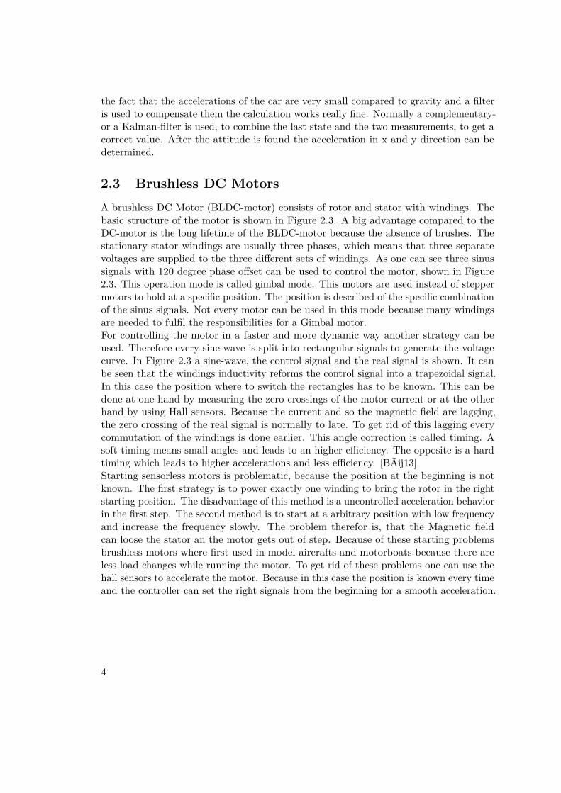
2.3 Brushless DC MotorsA brushless DC Motor (BLDC-motor) consists of rotor and stator with windings. Thebasic structure of the motor is shown in Figure 2.3. A big advantage compared to theDC-motor is the long lifetime of the BLDC-motor because the absence of brushes. Thestationary stator windings are usually three phases, which means that three separatevoltages are supplied to the three different sets of windings. As one can see three sinussignals with 120 degree phase offset can be used to control the motor, shown in Figure2.3. This operation mode is called gimbal mode. This motors are used instead of steppermotors to hold at a specific position. The position is described of the specific combinationof the sinus signals. Not every motor can be used in this mode because many windingsare needed to fulfil the responsibilities for a Gimbal motor.For controlling the motor in a faster and more dynamic way another strategy can beused. Therefore every sine-wave is split into rectangular signals to generate the voltagecurve. In Figure 2.3 a sine-wave, the control signal and the real signal is shown. It canbe seen that the windings inductivity reforms the control signal into a trapezoidal signal.In this case the position where to switch the rectangles has to be known. This can bedone at one hand by measuring the zero crossings of the motor current or at the otherhand by using Hall sensors. Because the current and so the magnetic field are lagging,the zero crossing of the real signal is normally to late. To get rid of this lagging everycommutation of the windings is done earlier. This angle correction is called timing. Asoft timing means small angles and leads to an higher efficiency. The opposite is a hardtiming which leads to higher accelerations and less efficiency. [BÃij13]Starting sensorless motors is problematic, because the position at the beginning is notknown. The first strategy is to power exactly one winding to bring the rotor in the rightstarting position. The disadvantage of this method is a uncontrolled acceleration behaviorin the first step. The second method is to start at a arbitrary position with low frequencyand increase the frequency slowly. The problem therefor is, that the Magnetic fieldcan loose the stator an the motor gets out of step. Because of these starting problemsbrushless motors where first used in model aircrafts and motorboats because there areless load changes while running the motor. To get rid of these problems one can use thehall sensors to accelerate the motor. Because in this case the position is known every timeand the controller can set the right signals from the beginning for a smooth acceleration.
4

Figure 2.1: Basic structure of the BLDC motor[AK14]
Figure 2.2: Control signals of a brushless gimbal motor
Figure 2.3: Control signal of a brushless controller
5


CHAPTER 3Method
This chapter is split in two main parts. The first part is about the basic structure forHardware and Software. It shows the decisions whether a servo with a brushless controlleror a programmable micro-controller should be used. Furthermore the decision of themotor is described and the advantages and disadvantages of the motors are explained. Thesecond part gives a brief description of the used micro-controller, the brushless controller,the integration of the brushless controller in the IMU program and the communicationto the terminal. Moreover a brief explanation of the terminal node for communicationwith the micro-controller is given.
3.1 Basic Structure
To prepare a clear structure, the cars tasks are split into low and high level tasks. Lowlevel tasks are controlling the signals of the brushless motor, reading the IMU overthe I2C interface and position tracking. High level tasks are for example visualizationand localization. As one can see low level tasks are dependent to the car and the usedcomponents while high level ones are more abstract. To present a flexible interface twoCPU’s are used to quickly exchange the vehicle or the main application. A well knownframework to program such flexible interfaces is ROS (Robot operating system). Thisframework consists of the roscore which serves as master-node and a arbitrary number ofother nodes which can communicate over messages. So future tasks can subscribe to thecontrol and response messages of the robot and interpret them. A detailed description forROS is shown in the paper [Ng09]. For running ROS a debian operating system is needed.Therefore a Raspberry PI is used because it’s small in size and is powerful enough to rundebian. Additionally a wireless connection can be established to provide a connection toother workstations. To process low level tasks, another CPU is needed which providesinterfaces for the used components and is fast and real time capable. In this case twomethods where tested. The first one was to use a MicroMaestro servo controller and
7

RaspberryPi
ROS
Arduino UNO Controller BLCD
IMU
SteeringServo
SerialUSB
Figure 3.1: Basic structure of the race car
additional hardware to control the car. The second one was to use an ArduinoUNO toprocess the data. Furthermore the low level sensors an actors have to be chosen to fitinto the given control structure. In Figure 3.1 the basic structure of the car is shown.
3.1.1 High Level CPU (Raspberry PI)
As mentioned above a Raspberry PI with ROS is set up for the Main application. Thesupported version of the Raspberry operating systems for ROS is Raspbean becauseit’s based on debian. Additionally a W-LAN stick is installed on the raspberry PI togrant access from other workstations. For communicating with the Arduino a Terminalnode has to be created. The communication to the low level CPU works over USB serialinterface with the boost library. Because the used IMU comes with a working programthe control messages for the other components are defined in a similar way to includethem into the program. To read the car’s status and control it, three ROS nodes areused. The Razor IMU node to read the IMU data an visualize it, the ROS joy node tocontrol the car via game pad and rviz to visualize the position of the car. To link thecaptured data to the right position on the car the ROS tf package is used.
3.1.2 Sensor Level CPU (Arduino UNO)
The sensor Level CPU is responsible for controlling the car, reading sensors and presentingthe data in a useful way. Traditionally RC-cares where powered from fuel engines. Thecarburetor of these fuel engines was controlled with a small servo motor. To make iteasy to switch from fuel engines to brushless or DC motors the controllers of thesemotors are also controlled by servo values. So the first idea was to use the MicroMaestrofor controlling the motor-controller and the steering of the car. The benefit of usingthe MicroMaestro was the tight structure and the quick and easy implementation of it.There is also no need to program a Motor controller, because the original one from theRC-car can be used. But there are less possibilities to integrate sensors in this interface.Additionally the motor controller is optimized for high accelerations and maximumspeed, but this car has to be able to move slowly to explore it’s ambient and there is no
8

possibility to alter the controller in this way. Additionally there is no speed responsefrom the motor and odometry sensors have to be added. So the next idea was to test anArduino UNO with a motor shield to integrate the controller and the sensors in the lowlevel CPU. The biggest benefit of this solution is that the Arduino is a flexible and easyprogrammable Microcontroller. At the other Hand a fully working motor controller has tobe programmed in C, a communication interface has to be implemented, and knowledgeof the used sensors is needed. Which is much more work than the first solution. Butusing the MicroMaestro limits the possibilities too much for this application. Especiallywhen adding new sensors it causes many problems. So the Arduino UNO is used fortesting the car.
3.1.3 Sensors and Actors
To control the car a steering and a motor has to be choosen. For the steering controlof the car a servo motor is taken, which is controllable by a PWM signal. The mostcommon motors are a DC motor and a brushless-motor. The brushless DC Motor hasmany advantages compared to the DC motor. It has a good dynamic response, a longeroperating life, less noise and a higher efficiency. Because of these advantages and thefact that BLDC motors are slowly replacing DC motor as well as there is no need foradditional odometry sensors, the decision was taken to use a BLDC motor. Finallysensors have been chosen, to measure the moved distance. The simplest choice for suchsensors is to use odometry sensors, because wheel encoders are really easy to read andvery cheep. If a brushless-motor is used the distance can be determined without using anyadditional sensor. Another cheep but more challenging method is to use an IMU for avelocity based sensor model. The odometry sensors tend to be more accurate but the IMUis better for harsh environments because odometry sensors can’t compensate problemslike wheel slip and bumps. To get the best of both for example a Kalman-filter can beused to combine both measurements. So a IMU and a odometry measurement methodare prepared for the localization task, because both of them are cheep to implement andthe car is prepared for many different tasks.
3.2 Components
3.2.1 Low-Level CPU
A Arduino UNO (Figure 3.2.1) is used to implement the sensor level CPU, becauseArduino offers many libraries for programming AVR micro-controllers and a activecommunity. But most of the programming work is done in C++ and not in the Arduinoenvironment, to present new flexible Arduino libraries. Additionally this design decisionmakes the code more readable and easier to use. For the IMU integration the RazorIMU ROS node is used, which serves a Arduino program to communicate with the IMU.Additionally a new serial interface library for Arduino is programmed. Furthermore thecalculation for the odometry-model is integrated into the program.
9

Figure 3.2: Arduino UNO
3.2.2 Motion Controller
For the brushless motor controller a brushless motor shield from LXRobotics is used tocontrol the motor. It consists of three FAN7093 High-Current PN Half-Bridge Driverto generate the signals for the motor. Furthermore three inputs are used for detectingthe rotor state. The used inputs and outputs on the ArduinoUNO are shown in Figure3.2.2 and Figure 3.2.2. Basically a state table is generated to match the rotor positionwith the actual state (Figure 3.2.2). On every pin change of the three inputs, the stateis determined and the next state is set. Therefore the next state is set for drivingforward and the previous is set for driving backward. Additionally the described timingof section 2.2 is implemented. To determine the position α degrees before the next stepa pose prediction is implemented. This prediction uses the moving average of the last Nstep-change timings.For driving the motor at different speed values the voltage has to be changed. Normallythis is done by using a pulse width modulation which is smoothed by the inductivity ofthe windings. Therefore a Timer is used in CTC mode. The CTC mode generates anInterrupt on 2 different timer matches, where the timer gets reseted on the higher one.Now the actual state of the driver is set on reset of the timer and reseted on the first
10

Phase AVR Pin Arduino PININ1 PC0 23IN2 PC1 24IN3 PC2 25
Figure 3.3: Input PIN Assignment Brushless Shield
Phase AVR Pin Arduino PINU PD2 4U_INH PD3 5V PD4 6V_INH PD5 11W PB0 14W_INH PD7 13
Figure 3.4: Output PIN Assignment Brushless Shield
compare match, if the angle is smaller than the angle prediction. As one can see the firstcompare match is to change the voltage level and the second one is to change the PWMfrequency of the signal. These PWM frequencies are in between 200Hz and 64kHz formotors with high or low inductivity.To ensure accurate speed behavior under different loads a controller has to be implemented.For implementing such a controller a PID controller or a fuzzy logic controller can beused. Because the mathematical model of the motor has to be known and adapted fordifferent motors while using a PID controller, a fuzzy logic controller is implemented.The structure of this controller is shown in Figure 3.2.2. The Fuzzifier converts the givenvalue into the fuzzy value which can be used to decide the next step. The Defuzzifierconverts the decision into a control value for the BLCD motor. The Inference engine andthe Rule base are used to change the output depending on the input. So the voltage canbe quickly adapted to load changes and keep the speed constant.Another advantage of the controller is to be able to start the BLCD motor with it’sfull torque. After the reference speed is reached the controller decreases the speed-valueautomatically. To start the motor only the first step has to be set because our brushlessmotor has hall sensors. In the results sections one can see that this approach is notworking really well and has to be improved. Because the motor controller is interruptdriven, it will never recognize if it has stopped unexpected. To get rid of this problem awatchdog-timer is implemented to guaranty a continuous control process.
11
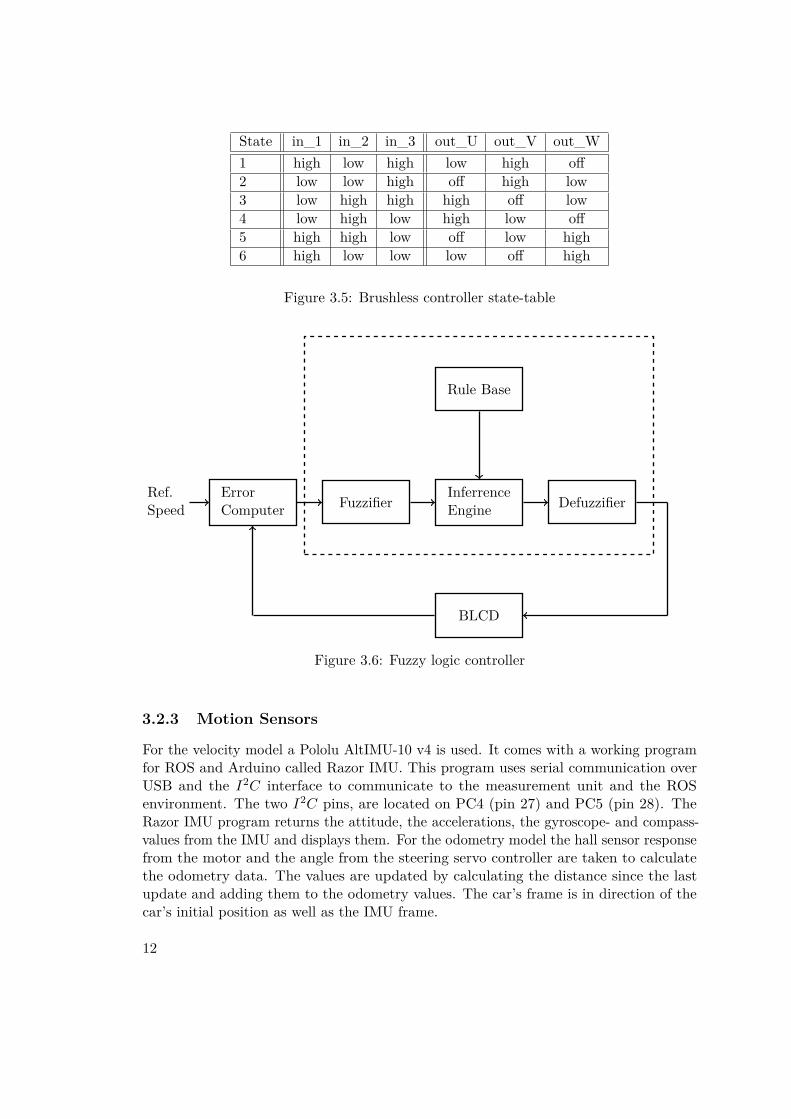
State in_1 in_2 in_3 out_U out_V out_W1 high low high low high off2 low low high off high low3 low high high high off low4 low high low high low off5 high high low off low high6 high low low low off high
Figure 3.5: Brushless controller state-table
FuzzifierRef.Speed
InferrenceEngine
Rule Base
Defuzzifier
BLCD
ErrorComputer
Figure 3.6: Fuzzy logic controller
3.2.3 Motion Sensors
For the velocity model a Pololu AltIMU-10 v4 is used. It comes with a working programfor ROS and Arduino called Razor IMU. This program uses serial communication overUSB and the I2C interface to communicate to the measurement unit and the ROSenvironment. The two I2C pins, are located on PC4 (pin 27) and PC5 (pin 28). TheRazor IMU program returns the attitude, the accelerations, the gyroscope- and compass-values from the IMU and displays them. For the odometry model the hall sensor responsefrom the motor and the angle from the steering servo controller are taken to calculatethe odometry data. The values are updated by calculating the distance since the lastupdate and adding them to the odometry values. The car’s frame is in direction of thecar’s initial position as well as the IMU frame.
12

3.2.4 Control Interface
Because there is an existing program which works with the Pololu IMU, this programis used and the motor controller and the odometry model are integrated. To keepcompatibility to the old Razor IMU Terminal node the existing messages are kept. Twonew control and response messages for the BLDC motor and a new odometry message isintroduced. The new commands are shown in Figure 3.2.4. For the IMU it looks like#YPRAG [yaw],[pitch],[roll],[acceleration x],[acceleration y],[acceleration z],[gyroscopex],[gyroscope y],[gyroscope z]. As one can see the orientation with roll pitch and yaw,the accelerations and the gyroscope values are given. The new odometry massage isformated as followed #OVD [frameNumber],[linear speed],[angular speed],[odometryx],[odometry y], [odometry θ],[covariance 1,1],[covariance 1,2],[covariance 1,3],[covariance2,1],[covarianz 2,2],[covarianz 2,3],[covarianz 3,1],[covarianz 3,2],[covarianz 3,3]. One cansee that the message consists of the speed and the steering angle as well as the odometrydata and its covariances.To handle the new messages a new ROS Terminal node has to be written. This nodebasically has to capture the serial data and publish them into ROS. Additionally ithas to subscribe to control messages and send commands on the serial interface. Theexpected ROS messages are geometry_msgs::Twist_data or sensor_msgs::Joy_data andthe presented ones are nav_msgs::Odometry and sensor_msgs::Imu. Additionally astamped tf message is presented to ROS.
command function response#vs [speed] sets the given speed #v [speed]#vg returns the actual speed #v [speed]#as [angle] sets the new steering angle #a [angle]#ag returns the actual angle #a [angle]
Figure 3.7: IMU serial commands
13


CHAPTER 4Result
To test the autonomous race car a RC car body from Tamya is used. Additionally aRaspberry PI 2, a GM brushless motor, the LXRobotics brushless shield, a gearbox, aArduino UNO and a Pololu AltIMU-10 v4 was used. For powering the Race car, theRapberry and the Arduino a standard 7.2V battery pack is used. Because the car droveto fast while testing finally a gearbox with a transmission of 7.4:1 was used to reduce thecars speed. The overall transmission is 61.2 to 1 with 66 mm wheel diameter.Another problem with the brushless shield was, that the given response pins for theback EMF where lying on the SPI interface of the Arduino. So the circuit paths whereremoved and only the Hall sensors where used for positional response on pins PC0 toPC2. For testing everything a Oscilloscope, the Razor IMU node, the ROS-joy node andRVIZ are used.
4.1 Motion Controller
The first part was to program a working brushless-motor controller. Therefore thementioned strategy in the method chapter was used. For testing the angle predictionuses a moving average of 6 updates, and the α-value is set to 5 degrees for a soft timing.Because of the limited numbers of timers on Arduino UNO the angle-prediction step andthe controlling task where moved into the PWM overflow interrupt to update the valueswith a constant period. That means that the PWM frequency is not adjustable to lowervalues, because the angle prediction has to be called fast enough to work in the right way.Compatibility to other brushless motors is mainly given because motors with the needof lower PWM frequencies are also moving slower and so lower frequencies are possibleagain.The fuzzy logic controller was implemented in a very simple way. It just adds or removesa specific value to or from the PWM value if the speed difference is in a defined corridorseen in Figure 4.1. Testing these values showed that such a simple controller is enough
15

for this task. Like the angle prediction the controller is also dependent from the PWMfrequency because if the frequency is higher it has more calls to add values to the PWMvalue and the controller overshoots the target more then with the lower one and viceversa.Theoretically it needs only one pulse to start the brushless motor but while testing itturns out that while startup the rotor can loose the magnetic field and stops. One methodto get rid of this problem is to detect, if the rotor stops and start it again. Therefore awatchdog-timer is implemented to detect if the pin change interrupts from the hall sensorsare appearing constantly. If such a stop is detected the watchdog-timer tries to restartthe motor. With this method it takes really long to start the motor and the startup isreally irregular. So another start routine was implemented. The motor detects the actualposition of the rotor and sets up the next state as usual. But now the controller doesn’twait for the next interrupt on the PCINT pins. It continues increasing the steps with adelay in range of milliseconds until the rotor has found a stable rotation. This rotation isdefined as stable if 6 states where correctly changed.The least speed the brushless driver managed to do was 24.0 turns per second. This isa minimum speed of 0.025 m/s when the transmission and the wheels are taken intoaccount. The maximum speed of the car is about 190 turns per second which is a totalspeed of 0.2 m/s. Without the gearbox the speed of the car would lie within 0.2 and1.6 m/s. One can see the timing diagram of the brushless controller’s PWM signal inFigure 4.1, which runs at 20kHz. The above picture shows the pulse with modulationpulses for a speed of 180 turns per second. The blue signal is about 1800µs long, whichis two periods on. So it can be easy seen that the motor turns in fact 180 times persecond. In the second picture the PWM signal of a speed of 27 turns per seconds isshown. Therefore it can be seen that the PWM of the yellow signal is 12ms long on.
speed difference value to add-0.5 < diff < 0.5 0diff > 0.5 1diff > 30.0 5diff < -0.1 -1diff < -30 -5
Figure 4.1: Fuzzy logic rule base
4.2 Motion Model
As described above the Razor IMU program is used and changed to the cars needs. Tointegrate the brushless controller, the main routine has to be changed. The initializefunction of the written brushless controller and the command decoding has to be integratedin the main loop. Everything else except setting the speed, works interrupt driven. A big
16

Figure 4.2: Timing diagram of the brushless controller. In both pictures the brushlessmotor’s PWM signals of the same situation with different speeds are shown. Additionallythere is a input which tells the half bridge driver if the signal is positive ore negative,which is not shown in these pictures. The first two signals (yellow and red) are negativeand the blue one is positive.
17

problem was that the Arduino serial library was to slow for the communication with themotor. To improve the speed, a new serial library with ring buffer is implemented forArduino. Now the car reacts very quickly to changes in speed and is smoothly controllableover game-pad. To respond to an odometry request a calculation of the actual positionis needed. Therefore the distance to the start point of the car is calculated incrementally.We have 6 values for this purpose the odometryx,y,θ point and the variance to this pointvariancex,y,θ. In Figure 4.2 the motion model for the Ackerman drive is calculated.Therefore the x, y and theta coordinates can be approximated like seen in Equationsone to four. To calculate the covariance the Jacobean matrices are needed. G describesthe advance from step to step and V matches the noise into the equation. This modelhas been simulated in Matlab (Figure 4.2 and was tested on the car (Figure 4.2 andFigure 4.2). Figure 4.2 shows the odometry message in RVIZ. Figure 4.2 shows the carsodometry output (red and blue) and the measured position of the car (green). It can beseen that the difference (in this case) between calculated and real position is a tenth ofa meter . While testing it turns out that the steering angle of the car is bigger, whenthe car is driving backwards. So a calculation correction value (130%) is multipliedto the angle, to make calculations more accurate and keep the covariance lower. Forimplementing a fully working Kalman-filter the odometry data and the covariance mustbe changed. Normally in ROS this is done by using offset variables to save the distancebetween detected position and the predicted position. Anyway 3 new commands whereincluded in the program to change the odometry data and the covariance of the carshown in Figure 4.2.
4.3 Control Interface
The terminal program is written in C++ with the boost library. Its base part is theserial interface for the communication with arduino. The interface consists of a serialreader in a single thread, which splits all messages at the command end delimeter whichis ’\n’ and buffers all received commands in a fifo-buffer. Afterwords the main programprocesses the collected data in the loop. To write commands a non threaded serialwriter is used. The terminal program reads ROS-messages and sends it to the Arduinoprogram. For testing the car two different possibilities are prepared. To control thecar by a joy-pad the node can directly read sensor-joy-messages. For controlling thecar with another motion program it can read velocity messages from ROS. For thiscalculation the distance between the car’s wheels is needed to calculate the steering angledepending to the angular velocity asin(dwheels∗ωv ). Afterwards the terminal sends thecommand with the serial interface until the #vs and the #as response appears in thebuffer. The program is also able to publish the IMU messages for the Razor IMU nodelike the Razor terminal program. Therefore a sensor_msgs::imu message is generatedout of the captured #YPRAG command. Which consists of the angular-velocities, thelinear-velocities, the orientation and it’s covariances. To visualize this data messagessimply the Razor IMU node is used. For publishing the odometry data a stampedodometry message is published on ROS containing x, y, z, a quaternion for the orientation
18

∆θ = δt ∗ v(t) ∗ tan(φ)dwheels
(4.1)
xodom = xodom + sin(θodom) (4.2)
xodom = yodom + cos(θodom) (4.3)
θodom = θodom + ∆θ (4.4)
G =1 0 −δt ∗ v(t) ∗ sin(θodom)0 1 δt ∗ v(t) ∗ cos(θodom)0 0 1
(4.5)
V =∆t ∗ cos(θ) 0∆t ∗ sin(θ) 0∆t∗tan( ∆θ
∆t )dwheels
∆t∗v(t)cos( ∆θ
∆t )2
(4.6)
Γ = σ1 00 σ2
(4.7)
Σ = G ∗ Σ ∗GT + V ∗ Γ ∗ V T (4.8)
Figure 4.3: Odometry calculation, Equation one to four are describing the positioncalculation and Equation five to eight are describing the motion covariance
and the car’s velocities. Additionally every message is marked with the frame id for tf.This message describes the distance between the base_link of the system and the actualframe id which can be displayed for example with rviz.
4.4 Conclusion and Future WorkIt has been shown how to build up a base frame for a autonomous race car. Thereforea brushless controller has been programmed and tested on an Arduino UNO and aRaspberry PI has been setted up with ROS to control the car. Furthermore an odometrymodel for an Ackerman drive has been derived and tested on the car. Additionally a IMUhas been integrated in the car to get extra information about the cars position. ThisIMU can be used in further tasks to improve the accuracy of the motion model of thecar. Therefore the calculated position from the odometry model can be merged with thedetermined position of the IMU. This should increase the positions accuracy and decreasethe growth of the covariance of the position. Another point to improve is the base frameof the car. To decrease the steering ‘noise’ and get even more accurate localization values,the base frame can be improved mechanically. The brushless controller takes only careon the motors hall sensors. So the timing angle has to be guessed because no responsefrom the current signal of the motor is given. To improve this controller additionally the
19

Figure 4.4: Odometry simulation
current signal can be monitored to improve the behaviour of the motor. In summary wecan say the car and the localization are working well, but there are many more tasks toimprove accuracy and behaviour of the car.
20

Figure 4.5: Odometry test with RVIZ
Figure 4.6: The Cars odometry data (red and blue) compared to the real position (green)
21

command arguments function#os xodom, yodom, θodom, sets odometry data
cov1,1, cov1,2, cov1,3 and variancecov2,1, cov2,2, cov2,3cov3,1, cov3,2, cov3,3
#oso xodom, yodom, θodom, sets odometry data#osv cov1,1, cov1,2, cov1,3 sets variance
cov2,1, cov2,2, cov2,3cov3,1, cov3,2, cov3,3
Figure 4.7: Odometry serial commands
22

Bibliography
[AK14] T.Ramesh A. Kiruthika, R. Agasthiya. Speed control of a sensored brushless dcmotor using flc. International Journal of Engineering Research and Technology,2014.
[BÃij13] Roland BÃijchi. Brushless-Motoren und -Regler. Verlag fuer Technik undHandwerk neue Medien GmbH, 2013.
[Gam01] Salah Sukkarieh Gamini. The aiding of a low-cost strapdown inertial mea-surement unit using vehicle modele constraints for land vehicle application.IEEE Transactions on robotics and automation, 2001.
[Ng09] Morgan Quigley Brian Gerkey Ken Conley Josh Faust Tully Foote JeremyLeibs Eric Berger Rob Wheeler Andrew Ng. Ros: an open-source robotoperating system. ICRA Workshop on Open Source Software, 2009.
[SJ14] Madhurima Chattopadhyay Sharad Jaiswal, Debjyoti Chowdhury. Perfor-mance analysis of sensored and sensorless drive of bldc motor using differenttypes of dc/dc converters in matlab/simulink platform. International Journalof Electrical, Electronics and Data Communication, 2014.
[VKSP13] A.K.Pandey Vinod KR Singh Patel. Modeling and performance analysis ofpid controlled bldc motor and different schemes of pwm controlled bldc motor.International Journal of Scientific and Research publications, 2013.
23