motor control - drone electronic speed controller
TRANSCRIPT
Drone Electronic Speed Controller(ESC) with XMC™, Gate Driver, OptiMOS™
October 2016

Learning objectives
› To demonstrate the implementation of sensorless FOC as Electronic Speed Controller (ESC) in quadcopter application
› Key software functions, a step-by-step implementation, and linking up with µC/Probe™ XMC™
› To use of µC/Probe™ to visualise data and fine-tune ESC
› After the learning of this PPT, users will be able to fine-tune FOC example software which is easy scalability for quadcopter ESC applications
2 2016-10-20 Copyright © Infineon Technologies AG 2016. All rights reserved.
Agenda (1/2)
Overview
Key features
Specification
System block diagram
Hardware overview
Software overview
Highlight MCU features
Get started
1
2
3
6
7
4
5
8
3 2016-10-20 Copyright © Infineon Technologies AG 2016. All rights reserved.
Agenda (2/2)
Resource listing 9
4 2016-10-20 Copyright © Infineon Technologies AG 2016. All rights reserved.

Electronic Speed Controller Reference Design- Overview
› The purpose of the training slides is to elaborate a low-cost and high-performance quadcopter ESC solution, using
– XMC™ PINUS Inverter
– 12V 2300KV 3 phase brushless motor
– DAVE™ 4 ESC example project - PMSM_FOC_SL_XMC13
› The HOT examples cover the key features and controls of the 3 phase brushless drone motor
5 2016-10-20 Copyright © Infineon Technologies AG 2016. All rights reserved.
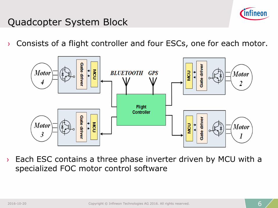
Quadcopter System Block
› Consists of a flight controller and four ESCs, one for each motor.
› Each ESC contains a three phase inverter driven by MCU with a specialized FOC motor control software
6 2016-10-20 Copyright © Infineon Technologies AG 2016. All rights reserved.
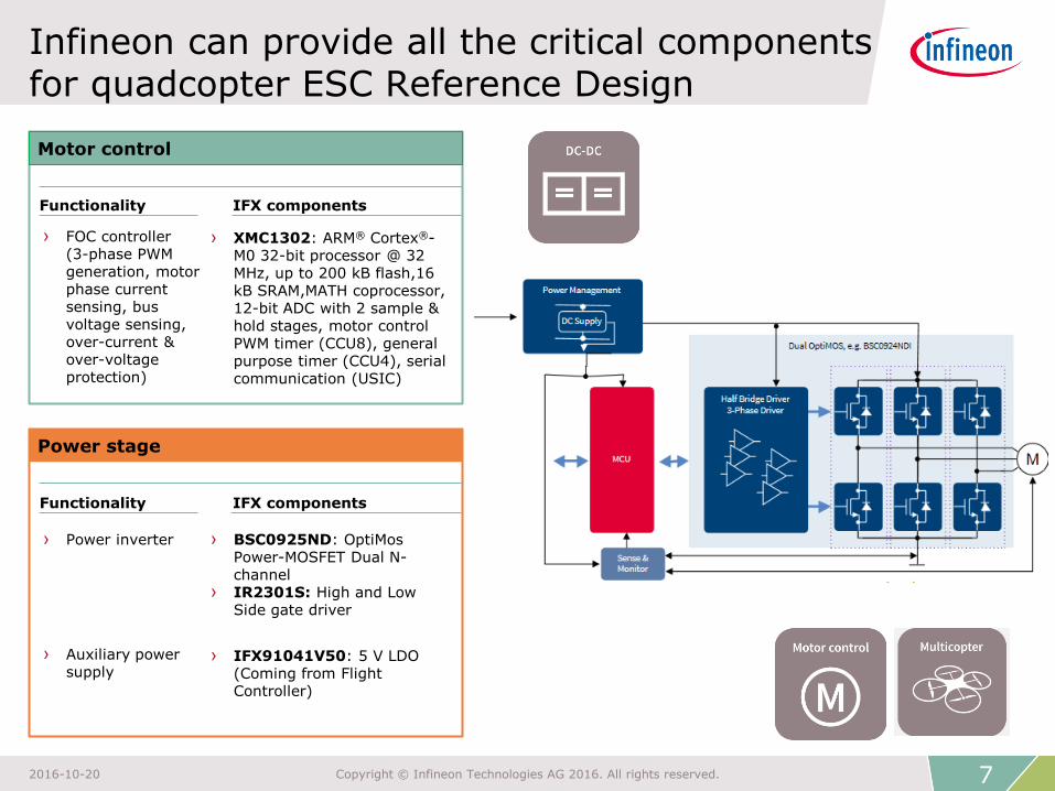
Infineon can provide all the critical components for quadcopter ESC Reference Design
Functionality IFX components
Motor control
Functionality IFX components
Power stage
› Power inverter › BSC0925ND: OptiMos Power-MOSFET Dual N-channel
› IR2301S: High and Low Side gate driver
› FOC controller (3-phase PWM generation, motor phase current sensing, bus voltage sensing, over-current & over-voltage protection)
› XMC1302: ARM® Cortex®-M0 32-bit processor @ 32 MHz, up to 200 kB flash,16 kB SRAM,MATH coprocessor, 12-bit ADC with 2 sample & hold stages, motor control PWM timer (CCU8), general purpose timer (CCU4), serial communication (USIC)
› IFX91041V50: 5 V LDO (Coming from Flight Controller)
› Auxiliary power supply
7 2016-10-20 Copyright © Infineon Technologies AG 2016. All rights reserved.

ESC Reference Design 3D PCB view
8 2016-10-20 Copyright © Infineon Technologies AG 2016. All rights reserved.
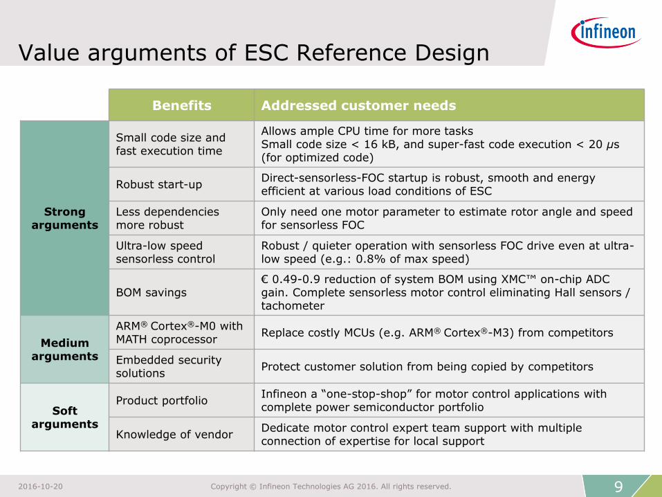
Benefits Addressed customer needs
Strong arguments
Small code size and fast execution time
Allows ample CPU time for more tasks Small code size < 16 kB, and super-fast code execution < 20 μs (for optimized code)
Robust start-up Direct-sensorless-FOC startup is robust, smooth and energy efficient at various load conditions of ESC
Less dependencies more robust
Only need one motor parameter to estimate rotor angle and speed for sensorless FOC
Ultra-low speed sensorless control
Robust / quieter operation with sensorless FOC drive even at ultra-low speed (e.g.: 0.8% of max speed)
BOM savings € 0.49-0.9 reduction of system BOM using XMC™ on-chip ADC gain. Complete sensorless motor control eliminating Hall sensors / tachometer
Medium arguments
ARM® Cortex®-M0 with MATH coprocessor
Replace costly MCUs (e.g. ARM® Cortex®-M3) from competitors
Embedded security solutions
Protect customer solution from being copied by competitors
Soft arguments
Product portfolio Infineon a “one-stop-shop” for motor control applications with complete power semiconductor portfolio
Knowledge of vendor Dedicate motor control expert team support with multiple connection of expertise for local support
Value arguments of ESC Reference Design
9 2016-10-20 Copyright © Infineon Technologies AG 2016. All rights reserved.

ESC Reference Design - Key features
Target application
› Quadcopter application
Key features
› Sensorless FOC control even at ultra-low speed
› Robust direct-sensorless-FOC startup
› Fast execution FOC with XMC™ Cortex M0
› XMC™ on-chip ADC gain to reduce system BOM cost
10 2016-10-20 Copyright © Infineon Technologies AG 2016. All rights reserved.
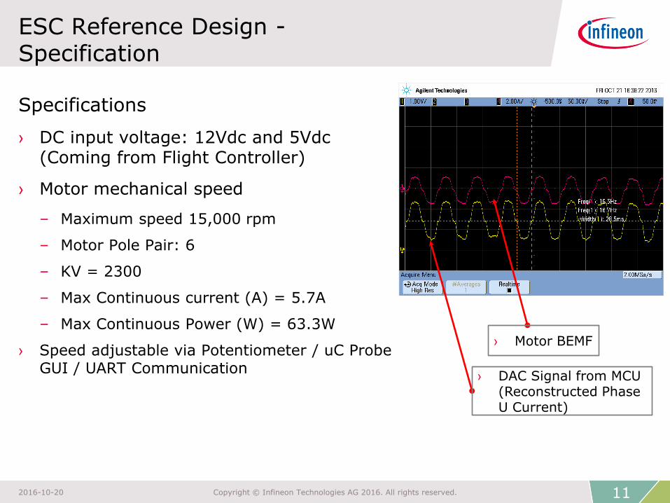
ESC Reference Design - Specification
Specifications
› DC input voltage: 12Vdc and 5Vdc (Coming from Flight Controller)
› Motor mechanical speed
– Maximum speed 15,000 rpm
– Motor Pole Pair: 6
– KV = 2300
– Max Continuous current (A) = 5.7A
– Max Continuous Power (W) = 63.3W
› Speed adjustable via Potentiometer / uC Probe GUI / UART Communication
11 2016-10-20 Copyright © Infineon Technologies AG 2016. All rights reserved.
› Motor BEMF
› DAC Signal from MCU (Reconstructed Phase U Current)
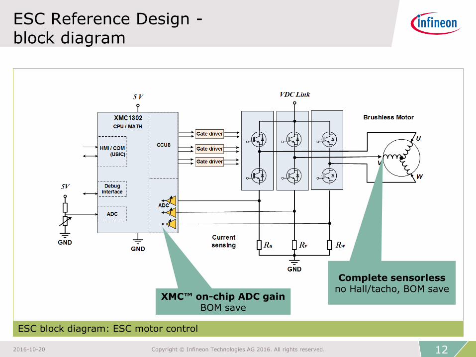
ESC Reference Design - block diagram
ESC block diagram: ESC motor control
XMC™ on-chip ADC gain BOM save
Complete sensorless no Hall/tacho, BOM save
12 2016-10-20 Copyright © Infineon Technologies AG 2016. All rights reserved.
ESC motor control - Hardware overview
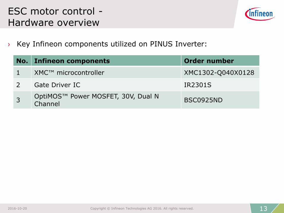
› Key Infineon components utilized on PINUS Inverter:
No. Infineon components Order number
1 XMC™ microcontroller XMC1302-Q040X0128
2 Gate Driver IC IR2301S
3 OptiMOS™ Power MOSFET, 30V, Dual N Channel
BSC0925ND
13 2016-10-20 Copyright © Infineon Technologies AG 2016. All rights reserved.
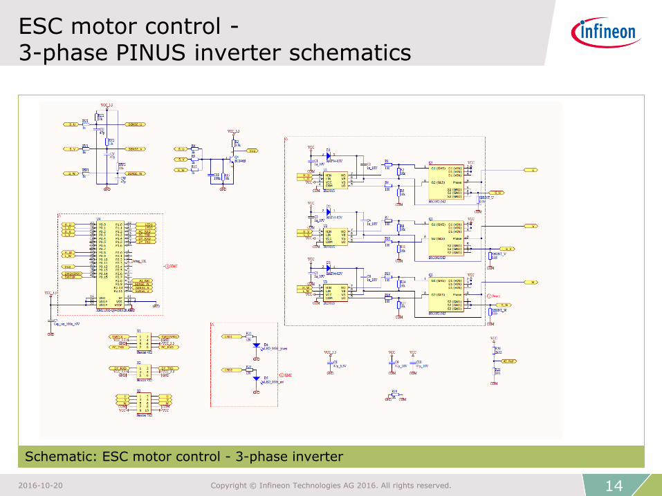
ESC motor control - 3-phase PINUS inverter schematics
Schematic: ESC motor control - 3-phase inverter
14 2016-10-20 Copyright © Infineon Technologies AG 2016. All rights reserved.

ESC motor control - Software overview (Torque Control Mode)
Flow chart: ESC motor control - software overview
15 2016-10-20 Copyright © Infineon Technologies AG 2016. All rights reserved.
BRAKEBOOTSTRAP
STOP
ERROR
FOC NORMAL
OPERATION
ROTOR PRE POSITIONING
Stop command
Read ADC POT
Direct FOC startup
Fault (Ctrap, over-voltage)
· Error handling
· Turn off CCU8 timers· Turn off inverter
· Ramp up/down· Fault monitoring
· Parameters Initialization
· Inverter Enable· Bootstrap capacitor
charging per phase at a time.
· PI Parameter Init · Amplifier bias voltage
calibration.
·
· Start PWM Generation
· Start PWM Generation· Aligned rotor to d-axis· FOC System Parameters Init
Once
ESC motor control - Highlight MCU features
› MATH coprocessor
– 38x faster sine, cosine and arctangent calculations
– High-resolution Park/Inverse Park Transforms at 24-bit in less than 1 µs
– 7x faster division compared to other ARM® Cortex®-M0 devices
› CCU8 PWM
– Generate PWM patterns for all kind of motors
– Interact with ADC for ADC triggering at sensorless control of motors
– Operate always in a safe state - even in an error condition
– Dead time control to minimum hardware effort
– 16-bit resolution for high precision space vector PWM generation
› ADC
– On-chip ADC gain (x1, x3, x6, or x12) to eliminate external Op-Amp
– Simultaneously sample of multiple analog channels
– Fast ADC reduces torque ripple due to minimized blind angle in sensorless FOC
– Used to sense motor three phase current as feedback to the system
16 2016-10-20 Copyright © Infineon Technologies AG 2016. All rights reserved.

ESC motor control - Get started - HW connections
› Connect BLDC motor U, V and W phases to PINUS Inverter
› Connect to Jlink Debugger SD
› Connect POT P2.3
› Connect to Drone BLDC Motor U,V,W
› VDC Link (12V)
› Supply +5V
› UART RX P1.4 › UART TX P1.5
› GND
› GND
› Connect to Jlink Debugger SC
17 2016-10-20 Copyright © Infineon Technologies AG 2016. All rights reserved.
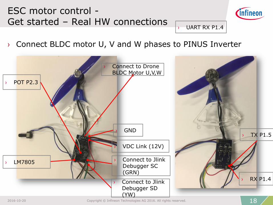
ESC motor control - Get started – Real HW connections
› Connect BLDC motor U, V and W phases to PINUS Inverter
› Connect to Jlink Debugger SD (YW)
› POT P2.3
› Connect to Drone BLDC Motor U,V,W
› VDC Link (12V)
› RX P1.4
› UART RX P1.4
› TX P1.5 › GND
› Connect to Jlink Debugger SC (GRN)
› LM7805
18 2016-10-20 Copyright © Infineon Technologies AG 2016. All rights reserved.

ESC motor control – Test Setup
19 2016-10-20 Copyright © Infineon Technologies AG 2016. All rights reserved.
› BLDC 3 Phase Motors
› PINUS ESC
› 3S LiPo Battery pack
› Potentiometer

ESC motor control - Get started - DAVE™ 4
› Download the latest DAVE™ 4 installer package from
DAVE™ (Version 4) - Development Platform for XMC™ Microcontrollers
› Installation requirements
1. PC with Windows 7, Windows 8.1, Windows 10, Windows Vista - 32bit & 64bit
2. RAM - 4 GB or more
3. Remember to install SEGGER J-Link when installing DAVE™ 4 (if not done so)
20 2016-10-20 Copyright © Infineon Technologies AG 2016. All rights reserved.
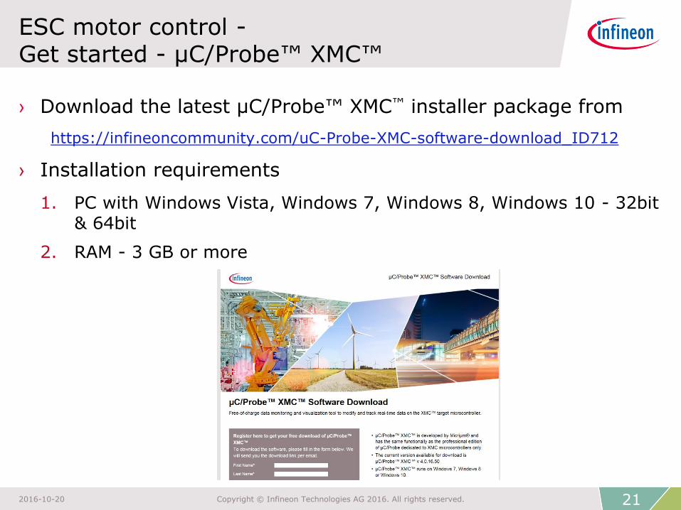
ESC motor control - Get started - µC/Probe™ XMC™
› Download the latest µC/Probe™ XMC™ installer package from
https://infineoncommunity.com/uC-Probe-XMC-software-download_ID712
› Installation requirements
1. PC with Windows Vista, Windows 7, Windows 8, Windows 10 - 32bit & 64bit
2. RAM - 3 GB or more
21 2016-10-20 Copyright © Infineon Technologies AG 2016. All rights reserved.
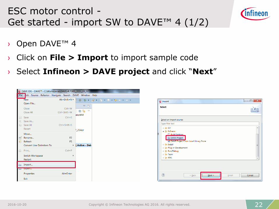
ESC motor control - Get started - import SW to DAVE™ 4 (1/2)
› Open DAVE™ 4
› Click on File > Import to import sample code
› Select Infineon > DAVE project and click “Next”
22 2016-10-20 Copyright © Infineon Technologies AG 2016. All rights reserved.
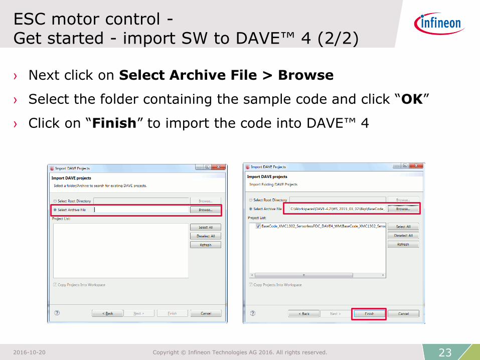
ESC motor control - Get started - import SW to DAVE™ 4 (2/2)
› Next click on Select Archive File > Browse
› Select the folder containing the sample code and click “OK”
› Click on “Finish” to import the code into DAVE™ 4
23 2016-10-20 Copyright © Infineon Technologies AG 2016. All rights reserved.
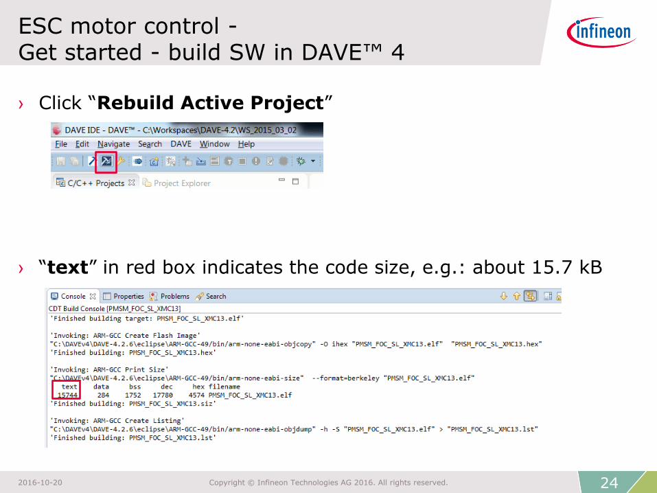
› Click “Rebuild Active Project”
› “text” in red box indicates the code size, e.g.: about 15.7 kB
ESC motor control - Get started - build SW in DAVE™ 4
24 2016-10-20 Copyright © Infineon Technologies AG 2016. All rights reserved.
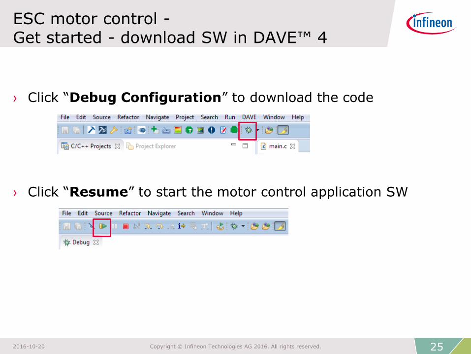
ESC motor control - Get started - download SW in DAVE™ 4
› Click “Debug Configuration” to download the code
› Click “Resume” to start the motor control application SW
25 2016-10-20 Copyright © Infineon Technologies AG 2016. All rights reserved.
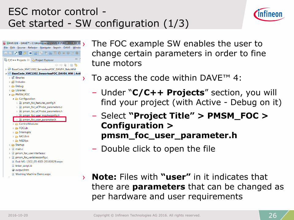
ESC motor control - Get started - SW configuration (1/3)
› The FOC example SW enables the user to change certain parameters in order to fine tune motors
› To access the code within DAVE™ 4:
– Under “C/C++ Projects” section, you will find your project (with Active - Debug on it)
– Select “Project Title” > PMSM_FOC > Configuration > pmsm_foc_user_parameter.h
– Double click to open the file
› Note: Files with “user” in it indicates that there are parameters that can be changed as per hardware and user requirements
26 2016-10-20 Copyright © Infineon Technologies AG 2016. All rights reserved.
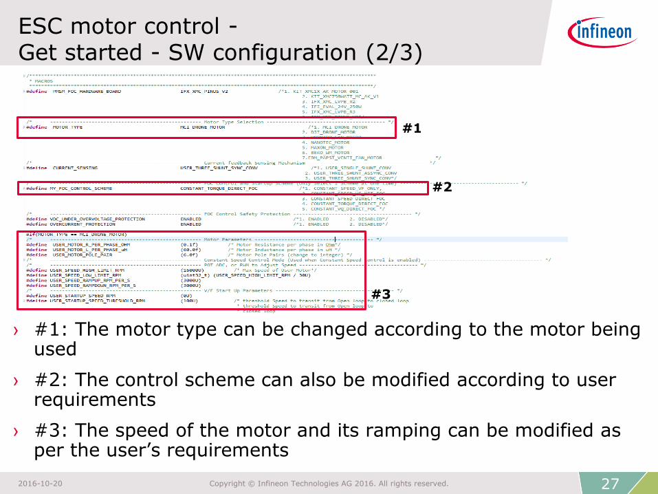
ESC motor control - Get started - SW configuration (2/3)
› #1: The motor type can be changed according to the motor being used
› #2: The control scheme can also be modified according to user requirements
› #3: The speed of the motor and its ramping can be modified as per the user’s requirements
#1
#2
#3
27 2016-10-20 Copyright © Infineon Technologies AG 2016. All rights reserved.

ESC motor control - Get started - SW configuration (3/3)
28 2016-10-20 Copyright © Infineon Technologies AG 2016. All rights reserved.
› #4: PINUS inverter is designed to make use of XMC1302 internal OP-Amp Gain for phase current ADC sensing
› #6: CCU8 PWM Peripherals configuration
› #5: Macros to configure based on Inverter HW specs
#4
#5
#6
ESC motor control - Get started - pmsm_foc_user_parameters.h
› XMC™ can use fixed points numbers / integers to represent floating-point quantities of the physical value (e.g. : in SI unit)
› User can defined different level of configurations based on Inverter hardware specs
29 2016-10-20 Copyright © Infineon Technologies AG 2016. All rights reserved.
ESC motor control - Get started - pmsm_foc_user_mcuhwconfig.h
› MCU hardware resource management (VADC, CCU8)
› NVIC interrupts service routine resource management
› Debugging IO (DAC functionality)
30 2016-10-20 Copyright © Infineon Technologies AG 2016. All rights reserved.

ESC motor control - Get started - starting µC/Probe™ XMC™
› Double-click “*.wspx” file in the DAVE™ 4 IDE to start µC/Probe™
› Click “Run” to control the speed of the motor using µC/Probe™
Run
.wspx file
31 2016-10-20 Copyright © Infineon Technologies AG 2016. All rights reserved.
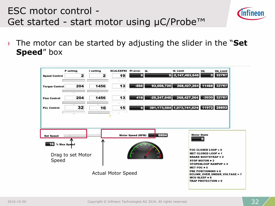
ESC motor control - Get started - start motor using µC/Probe™
› The motor can be started by adjusting the slider in the “Set Speed” box
Actual Motor Speed
Drag to set Motor Speed
32 2016-10-20 Copyright © Infineon Technologies AG 2016. All rights reserved.
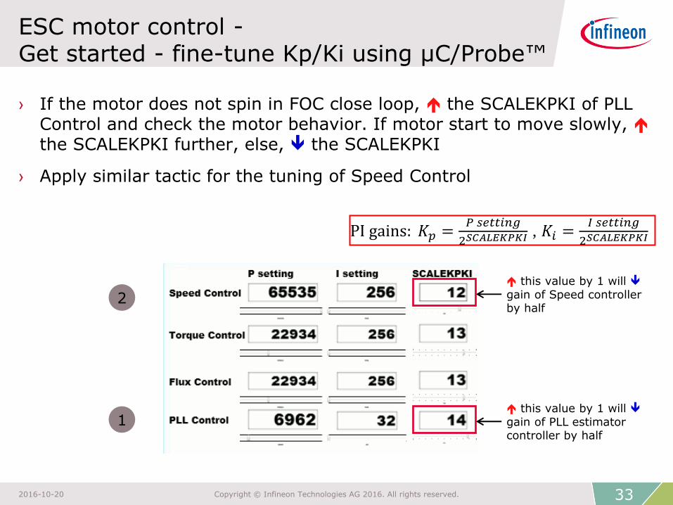
ESC motor control - Get started - fine-tune Kp/Ki using µC/Probe™
› If the motor does not spin in FOC close loop, the SCALEKPKI of PLL Control and check the motor behavior. If motor start to move slowly, the SCALEKPKI further, else, the SCALEKPKI
› Apply similar tactic for the tuning of Speed Control
this value by 1 will gain of Speed controller by half
this value by 1 will gain of PLL estimator controller by half
2
1
PI gains: 𝐾𝑝 =𝑃 𝑠𝑒𝑡𝑡𝑖𝑛𝑔
2𝑆𝐶𝐴𝐿𝐸𝐾𝑃𝐾𝐼 , 𝐾𝑖 =𝐼 𝑠𝑒𝑡𝑡𝑖𝑛𝑔
2𝑆𝐶𝐴𝐿𝐸𝐾𝑃𝐾𝐼
33 2016-10-20 Copyright © Infineon Technologies AG 2016. All rights reserved.
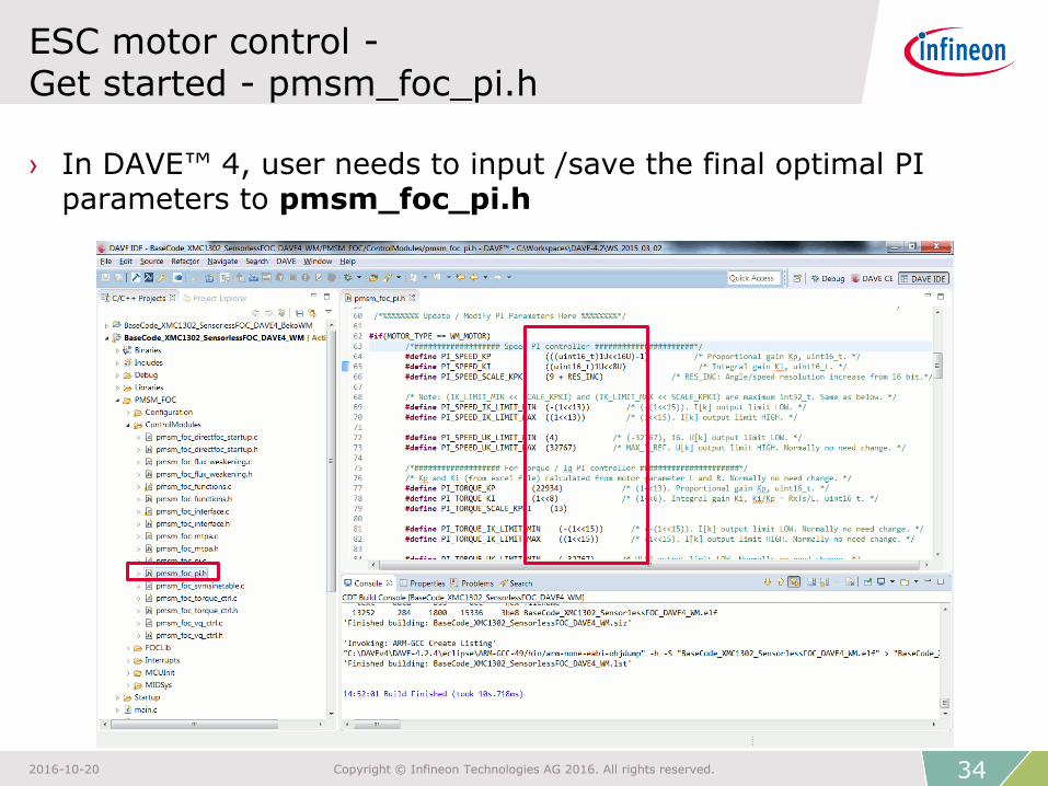
ESC motor control - Get started - pmsm_foc_pi.h
› In DAVE™ 4, user needs to input /save the final optimal PI parameters to pmsm_foc_pi.h
34 2016-10-20 Copyright © Infineon Technologies AG 2016. All rights reserved.
ESC motor control - Key features
1. Sensorless FOC control even at ultra-low speed
2. Robust direct-sensorless-FOC startup
3. Fast execution FOC with XMC™ Cortex M0
4. XMC™ on-chip ADC gain to reduce system BOM cost
35 2016-10-20 Copyright © Infineon Technologies AG 2016. All rights reserved.

1. Key feature - sensorless FOC control even at ultra-low speed

No Inv. Park Transform Fast code execution
Complete sensorless no Hall/tacho, BOM save
ESC - sensorless FOC - Block diagram
Block diagram: ESC motor control - sensorless FOC
XMC™ HW CORDIC Fast calculation with
XMC1300 MATH coprocessor
PLL Observer Unique in industry. Only 1 motor parameter required
for sensorless control
Ref_IdVd
Vq
ω
φ
Motor
u
v
w
Iq
Iα
Iβ
Id
θ
|Vref |-
-
Θ+
VDC
ADC_VDC
Trigger
ADCs
...L
Iq
PI-Controller
Id
PI-Controller
1, 2, or 3x
Rshunt
VDC
+
+
3-Phase
2-Level
Voltage
Source
Inverter
(VSI)
PWM-Unit
with
integrated
deadtime
control
Cartesian
to Polar
Transform
SVM
Modulator
Park
TransformADC
PLL
Observer
(or rotor
sensor)
SWSW (LIB)
Legend:
GainHW
Ref_Iq
Iu
Iv
Iw
Clarke
Transform
Current
Calculation
User Configuration
37 2016-10-20 Copyright © Infineon Technologies AG 2016. All rights reserved.
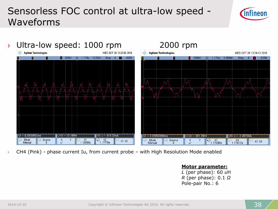
› Ultra-low speed: 1000 rpm 2000 rpm
› CH4 (Pink) - phase current Iu, from current probe – with High Resolution Mode enabled
Sensorless FOC control at ultra-low speed - Waveforms
Motor parameter: L (per phase): 60 uH R (per phase): 0.1 Ω Pole-pair No.: 6
38 2016-10-20 Copyright © Infineon Technologies AG 2016. All rights reserved.
2. Key feature - robust direct-sensorless-FOC startup
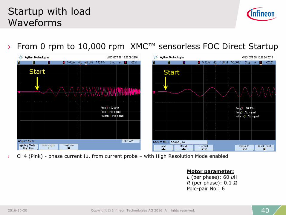
› From 0 rpm to 10,000 rpm XMC™ sensorless FOC Direct Startup
› CH4 (Pink) - phase current Iu, from current probe – with High Resolution Mode enabled
Startup with load Waveforms
Motor parameter: L (per phase): 60 uH R (per phase): 0.1 Ω Pole-pair No.: 6
Start Start
40 2016-10-20 Copyright © Infineon Technologies AG 2016. All rights reserved.

XMC™ sensorless FOC with load Waveform @ 15000 rpm VDC = 12V, 5A
Waveforms: Drone
Channel 4 (pink): Current of fan motor Phase U (measured by current probe, 0.1V/A)
41 2016-10-20 Copyright © Infineon Technologies AG 2016. All rights reserved.
3. Key feature – Fast Execution FOC with XMC™ Cortex M0
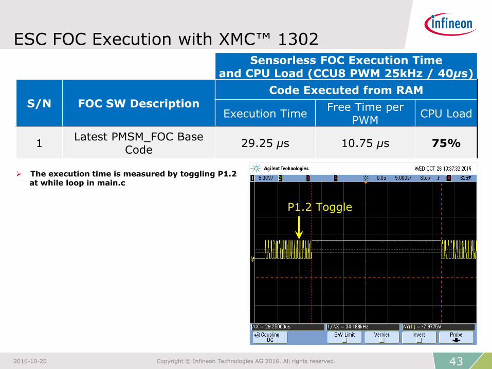
ESC FOC Execution with XMC™ 1302 Sensorless FOC Execution Time
and CPU Load (CCU8 PWM 25kHz / 40µs)
S/N FOC SW Description
Code Executed from RAM
Execution Time Free Time per
PWM CPU Load
1 Latest PMSM_FOC Base
Code 29.25 µs 10.75 µs 75%
43 2016-10-20 Copyright © Infineon Technologies AG 2016. All rights reserved.
The execution time is measured by toggling P1.2 at while loop in main.c
P1.2 Toggle
5. Key feature - XMC™ on-chip ADC gain
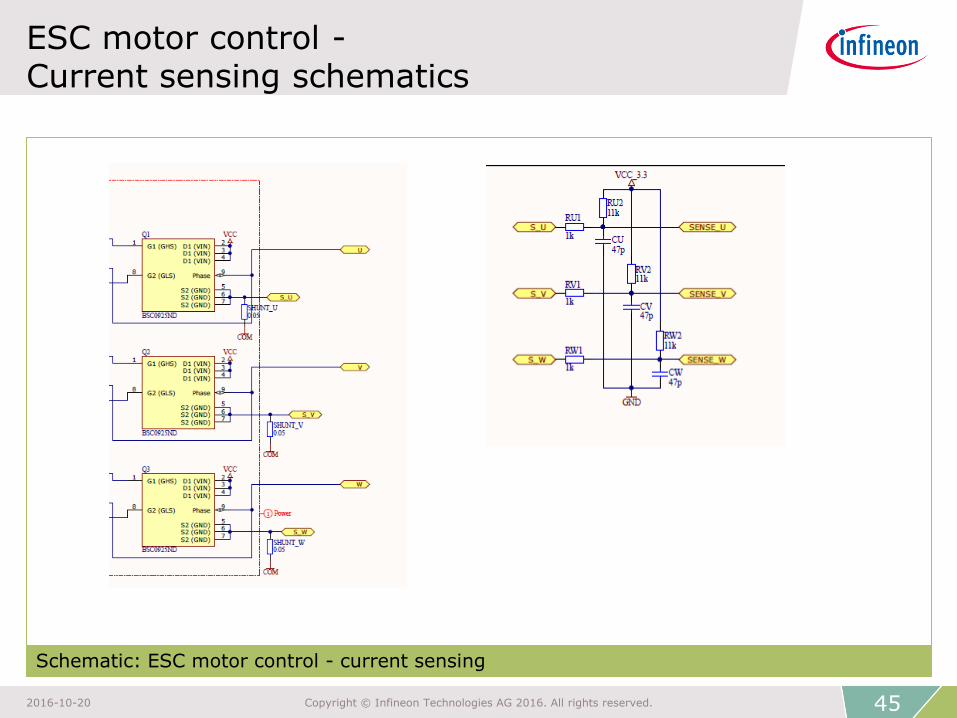
ESC motor control - Current sensing schematics
Schematic: ESC motor control - current sensing
45 2016-10-20 Copyright © Infineon Technologies AG 2016. All rights reserved.

ESC motor control - XMC™ on-chip ADC gain for current sensing
› R1 limits current flow in / out of XMC1302 ADC pin. R2 offset ADC input
› e.g.: for an application G=6, Rdc=0.05 Ω, R1=1 kΩ, R2=11 kΩ, C1=47 pF
$ cost saving XMC1302
Vdd (5V)
GND
Rdc
Idc
GND
R1
C1
R2
ADC
with gain
G
VADC
𝑉𝐴𝐷𝐶 ≈𝐺𝑅1
𝑅1 + 𝑅2𝑉𝑑𝑑 +
𝑅2
𝑅1 + 𝑅2𝐺 ∙ 𝑅𝑑𝑐∙ 𝐼𝑑𝑐
Gain: 5.5 Offset: 2.5 V
46 2016-10-20 Copyright © Infineon Technologies AG 2016. All rights reserved.
Resource listing
› ESC motor control
– Documentation
− Infineon multicopter solution landing page
– DAVE™ project
47 2016-10-20 Copyright © Infineon Technologies AG 2016. All rights reserved.
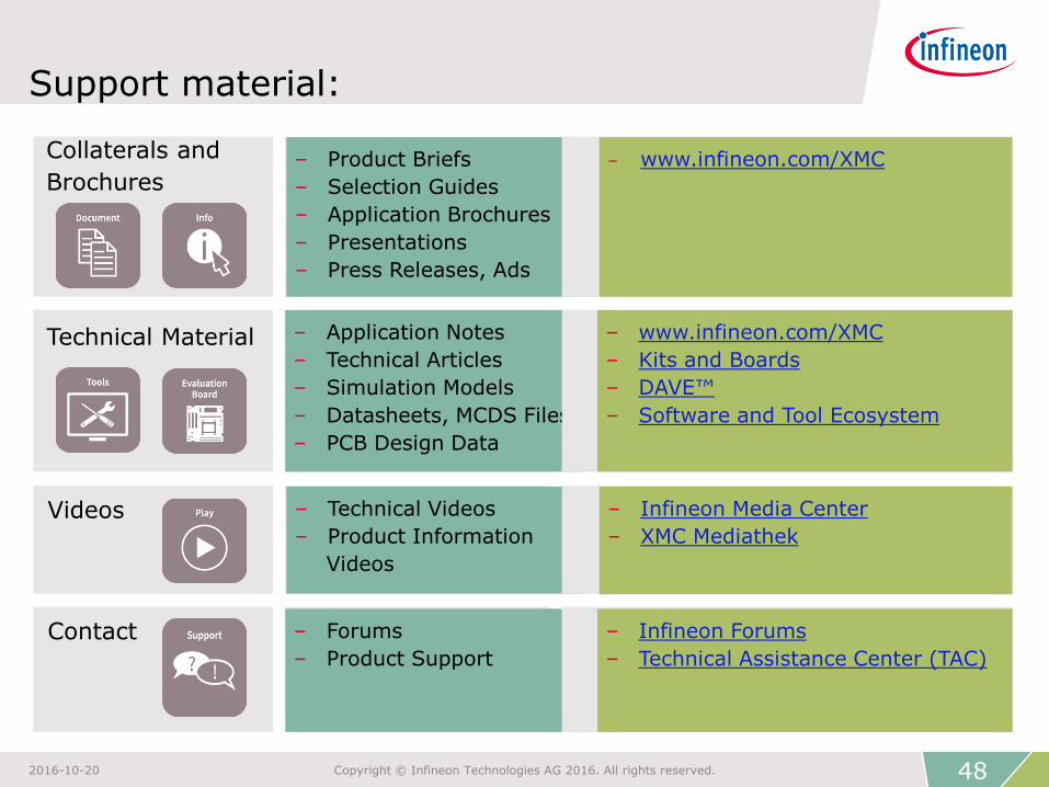
– Product Briefs
– Selection Guides
– Application Brochures
– Presentations
– Press Releases, Ads
– Application Notes
– Technical Articles
– Simulation Models
– Datasheets, MCDS Files
– PCB Design Data
– Technical Videos
– Product Information
Videos
– Forums
– Product Support
Support material:
Collaterals and
Brochures
Technical Material
Videos
Contact
– www.infineon.com/XMC
– www.infineon.com/XMC
– Kits and Boards
– DAVE™
– Software and Tool Ecosystem
– Infineon Media Center
– XMC Mediathek
– Infineon Forums
– Technical Assistance Center (TAC)
48 2016-10-20 Copyright © Infineon Technologies AG 2016. All rights reserved.
Glossary abbreviations (1/2)
› AC Alternating Current
› ADC Analog-to-Digital Converter
› BEMF Back ElectroMotive Force
› BOM Bill Of Material
› CPU Central Processing Unit
› DAC Digital-to-Analog Converter
› DAVE™ Digital Application Virtual Engineer
› DC Direct Current
› FOC Field-Oriented Control
› GUI Graphical User Interface
› HMI Human-Machine Interface
› HW Hardware
49 2016-10-20 Copyright © Infineon Technologies AG 2016. All rights reserved.
Glossary abbreviations (2/2)
› IDE Integrated Development Environment
› IGBT Insulated-Gate Bipolar Transistor
› MCU MicroController Unit
› PLL Phase-Locked Loop
› PMSM Permanent Magnet Synchronous Motor
› PWM Pulse Width Modulation
› RAM Random-Access Memory
› SW Software
› SWD Serial Wire Debug
› UART Universal Asynchronous Receiver / Transmitter
› USIC Universal Serial Interface Channel
› XMC™ Cross-Market Microcontrollers
50 2016-10-20 Copyright © Infineon Technologies AG 2016. All rights reserved.
The information given in this training materials is given as a hint for the implementation of the Infineon Technologies component only and shall not be regarded as any description or warranty of a certain functionality, condition or quality of the Infineon Technologies component.
Infineon Technologies hereby disclaims any and all warranties and liabilities of any kind (including without limitation warranties of non-infringement of intellectual property rights of any third party) with respect to any and all information given in this training material.
Disclaimer
