motor control gear - voltimum · pdf fileare direct-on-line and star-delta. ... instructions...
TRANSCRIPT
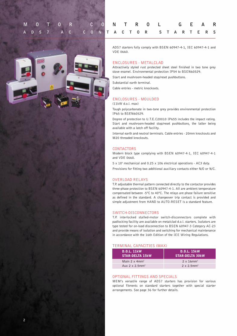
ADS7 starters fully comply with BSEN 60947-4-1, IEC 60947-4-1 and
VDE 0660.
ENCLOSURES - METALCLADAttractively styled rust protected sheet steel finished in two tone grey
stove enamel. Environmental protection IP54 to BSEN60529.
Start and mushroom-headed stop/reset pushbuttons.
Substantial earth terminal.
Cable entries - metric knockouts.
ENCLOSURES - MOULDED(11kW d.o.l. max)
Tough polycarbonate in two-tone grey provides environmental protection
IP65 to BSEN60529.
Degree of protection to U.T.E.C20010 IP655 includes the impact rating.
Start and mushroom-headed stop/reset pushbuttons, the latter being
available with a latch off facility.
Internal earth and neutral terminals. Cable entries - 20mm knockouts and
M20 threaded knockouts.
CONTACTORSModern block type complying with BSEN 60947-4-1, IEC 60947-4-1
and VDE 0660.
5 x 10⁶ mechanical and 0.25 x 10⁶ electrical operations - AC3 duty.
Provisions for fitting two additional auxiliary contacts either N/O or N/C.
OVERLOAD RELAYST.P. adjustable thermal pattern connected directly to the contactor provides
three-phase protection to BSEN 60947-4-1. All are ambient temperature
compensated between -5ºC to 40ºC. The relays are phase failure sensitive
as defined in the standard. A changeover trip contact is provided and
simple adjustment from HAND to AUTO-RESET is a standard feature.
SWITCH-DISCONNECTORST.P. interlocked stalled-motor switch-disconnectors complete with
padlocking facility are available on metalclad d.o.l. starters. Isolators are
type tested for on-load disconnection to BSEN 60947-3 Category AC-23
and provide means of isolation and switching for mechanical maintenance
in accordance with the 16th Edition of the IEE Wiring Regulations.
TERMINAL CAPACITIES (MAX)
D.O.L. 11kW D.O.L. 15kWSTAR-DELTA 15kW STAR-DELTA 30kW
Main 2 x 4mm2 2 x 16mm2
Aux 2 x 2.5mm2 2 x 2.5mm2
OPTIONAL FITTINGS AND SPECIALSMEM’s versatile range of ADS7 starters has provision for various
optional fitments on standard starters together with special starter
arrangements. See page 36 for further details.
M O T O R C O N T R O L G E A RA D S 7 A C C O N T A C T O R S T A R T E R S
2
29182 MEM MotorControlGear new 30/7/02 10:45 Page 5

3
A D S 7 S E L E C T I O N O F S T A R T E R S A N D O V E R L O A D R E L A Y S
Motor starters have two basic forms of operation either
automatic or manual. Manual starters are generally more
economic but less versatile and are normally only suitable for
infrequent starting of smaller motors.
Automatic starters of the contactor type are rated for frequent
duty, high mechanical durability and electrical life with the
facility for remote control.
THREE PHASE STARTERS FOR SQUIRREL CAGE MOTORSThe control of current and torque of AC induction motors
requires consideration when selecting a starter. The most
common methods of starting a three-phase squirrel cage motor
are direct-on-line and star-delta.
The starting current of a standard squirrel cage motor when
switched direct on to the supply (direct-on-line) is approximately
6 to 8 times full load current and may develop up to 150% full
load torque. This method of starting is not always permissible,
particularly on larger machines due to the following:
(a) Limitation of switching peaks by supply authority or back up
circuit breaker.
(b) Starting peak will cause volt drop which can result in
overheating of motor and supply cables.
(c) High starting torque can under certain load conditions cause
excessive mechanical wear.
In these conditions reduced voltage starters must be used and the
most common is the star-delta starter. This method of starting
restricts the starting current to 1⁄3 of direct switching i.e. 2 to 3
times FLC with a corresponding drop in starting torque.
An alternative is the auto-transformer starter, which is normally
used where a higher starting torque is required to accelerate the
drive or the motor only has three terminals. The starting current
and torque are determined by the auto-transformer tapping used.
The table below gives the appropriate starting current and torque
likely to be obtained.
METHOD OF STARTING STARTINGSTARTING CURRENT TORQUE
(% FLC) (%FLT)
Direct-on-line 600/800 100/150
Star delta 200/300 30/50
Auto transformer 100/400 16/80
(according to tapping used)
TWO SPEED STARTERSThese fall into two categories: starters for dual wound motors:
and starters for tapped wound or pole change motors. In both
instances they are direct-on-line. The dual wound motor has two
separate windings on the stator and accordingly one contactor
and overload relay is required per winding.
On tapped wound motors, three contactors are required and two
overload relays, one for each speed.
SINGLE PHASE STARTERSSmall capacitor squirrel cage motors have a centrifugal switch
for opening the starting winding or capacitor and a standard
direct-on-line starter is suitable for this function. Care must be
taken to ensure the starter is connected in accordance with the
instructions for single phase applications.
On larger motors, series parallel switching is the most common
and a special starter is required.
In addition there are split-phase motors having various switching
configurations and a connection diagram is often necessary to
ensure the correct starter is supplied.
STATOR AND ROTOR STARTERS FOR SLIPRING MOTORSThis type of starter switches the stator direct on to the supply.
The current taken is limited to approximately 125-200% FLC by
means of resistances connected to the rotor windings via
sliprings. In addition to limiting the starting current, the
resistances improve the power factor and based on current values
above, the motor would develop 100-175% full load torque.
As the motor accelerates the starting resistance is cut out of
circuit by one or more rotor contactors, depending on motor
rating, under time control to provide smooth acceleration.
Slipring motors are therefore ideal for high inertia loads such as
cranes, crushers, fans and mill drives requiring starting torques
up to 200% FLT where the acceleration can be controlled and
matched to supply and load restrictions. In addition, the
resistances can be rated to provide speed control and plug
braking of the motor.
SELECTION OF OVERLOAD RELAYSOverload relays are designed to operate over a given current
range which is indicated by the rating label. It is advisable to
select a relay where the motor rated FLC corresponds with the
upper end of the scale so as to permit a setting lower than the
motor rated FLC i.e. the actual running current, if this is known.
Adequate protection is however obtained if the pointer is set to
the motor rated FLC.
BACK-UP PROTECTION FOR OVERLOAD RELAYSThe use of the SCPD (short circuit protective device) given in the
table on page 9 ensures co-ordination Type 2 to BSEN 60947-4-1.
This ensures that the relay characteristic performance is
unaltered in the event of a short-circuit on the load side of the
relay when backed up by the selected SCPD. The SCPD is further
chosen so as NOT to intersect with the relay curve at a current
lower than the stalled motor current, thus ensuring
discrimination and avoiding operation during starting.
RELAYS USED WITH STAR-DELTA STARTERSOn automatic star-delta starters the overload relay is connected
in the delta loop and may be marked either with the line current
to the motor or the delta loop current of the motor. (This equals
0.58 x line current).
If the relay is marked with delta loop current the motor line
current x 0.58 should correspond to the setting scale mark on
the relay.
The reduced starting current permits the use of smaller fuses
than would be selected for d.o.l. starting as described above; but
at some loss of selectivity on high overloads.
In all cases the maximum SCPD stated for back-up protection of
the overload relay must not be exceeded.
29182 MEM MotorControlGear new 30/7/02 10:45 Page 6

4
M O T O R C O N T R O L G E A RA D S 7 E N C L O S E D A C C O N T A C T O R S T A R T E R S
Spares - Page 7. Dimensions - Pages 11-12. For higher rated motor starters see page 21.
D.O.L. 15kW MAX., STAR-DELTA 30kW MAX.
METALCLAD IP54
FULL LOAD CURRENT OVERLOAD LIST NO. ACCORDING TO COIL VOLTAGE 50Hz(415V MAX, 3ph, AC-3) RELAY CONTROL VOLTAGES OTHER THAN THOSE LISTED ARE AVAILABLE
TO SPECIAL ORDER.
220 ... 240V 380 ... 415VA kW hp LIST NO. STARTER LESS OVERLOAD STARTER LESS OVERLOADDirect-on-line, surface mounting0.74 - 1.11 0.37 0.5 TT871.11 - 1.66 0.55 0.75 TT881.66 - 2.5 1.1 1.5 TT892.5 - 3.7 1.5 2.0 TT903.7 - 5.6 2.5 3.4 TT91 27ADS1X 47ADS1X5.6 - 8.4 4.0 5.5 TT928.4 - 11.9 5.5 7.5 TT9311.4 - 16.0 7.5 10 TT9416.0 - 23.0 11 15 TT104 27ADS2X 47ADS2X23.0 - 33.0 15.0 20 TT96 27ADS3X 47ADS3XAdaptor for ADS6 aperture 67ADP, painted
Direct-on-line, surface mounting, with switch disconnector0.74 - 1.11 0.37 0.5 TT871.11 - 1.66 0.55 0.75 TT881.66 - 2.5 1.1 1.5 TT892.5 - 3.7 1.5 2.0 TT90 27ADSA1X 47ADSA1X3.7 - 5.6 2.5 3.4 TT915.6 - 8.4 4.0 5.5 TT928.4 - 11.9 5.5 7.5 TT9311.4 - 16.0 7.5 10 TT9416.0 - 23.0 11 15 TT104 27ADSA2X 47ADSA2X23.0 - 33.0 15.0 20 TT96 27ADSA3X 47ADSA3X
29182 MEM MotorControlGear new 30/7/02 10:45 Page 7

5
A D S 7 E N C L O S E D A C C O N T A C T O R S T A R T E R S
FULL LOAD CURRENT OVERLOAD LIST NO. ACCORDING TO COIL VOLTAGE 50Hz(415V MAX, 3ph, AC-3) RELAY CONTROL VOLTAGES OTHER THAN THOSE LISTED ARE AVAILABLE
TO SPECIAL ORDER.
220 ... 240V 380 ... 415VA kW hp LIST NO. STARTER LESS OVERLOAD STARTER LESS OVERLOADDirect-on-line, surface mounting, two - direction (forward and reverse)0.74 - 1.11 0.37 0.5 TT871.11 - 1.66 0.55 0.75 TT881.66 - 2.5 1.1 1.5 TT892.5 - 3.7 1.5 2.0 TT90 27ARD1X 47ARD1X3.7 - 5.6 2.5 3.4 TT915.6 - 8.4 4.0 5.5 TT928.4 - 11.9 5.5 7.5 TT9311.4 - 16.0 7.5 10 TT9416.0 - 23.0 11 15 TT104 27ARD2X 47ARD2X23.0 - 33.0 15.0 20 TT96 27ARD3X 47ARD3XStar-delta, surface mounting4.3 - 6.4 3.0 4.0 TT976.4 - 9.7 5.0 6.8 TT989.7 - 14.5 7.5 10 TT99 27SDA2X 47SDA2X14.5 - 20.6 10.0 13.5 TT10019.7 - 27.7 15.5 20 TT10126.0 - 42.0 22.0 30 TT102
27SDA3X 47SDA3X38.0 - 57.0 30.0 40 TT103Star-delta, surface mounting, with switch - disconnector4.3 - 6.4 3.0 4.0 TT976.4 - 9.7 5.0 6.8 TT989.7 - 14.5 7.5 10.0 TT99 27SDAA2X 47SDAA2X14.5 - 20.6 10.0 13.5 TT10019.7 - 27.7 15.5 20.0 TT10126.0 - 42.0 22.0 30.0 TT102
27SDAA3X 47SDAA3X38.0 - 57.0 30.0 40.0 TT103
D.O.L. 11kW MAX. MOULDED IP65
FULL LOAD CURRENT OVERLOAD LIST NO. ACCORDING TO COIL VOLTAGE 50Hz(415V, 3ph, AC-3) RELAY CONTROL VOLTAGES OTHER THAN THOSE LISTED ARE AVAILABLE
TO SPECIAL ORDER.
220 ... 240V 380 ... 415VA kW hp LIST NO. STARTER LESS OVERLOAD STARTER LESS OVERLOADDirect-on-line, surface mounting0.74 - 1.11 0.37 0.5 TT871.11 - 1.66 0.55 0.75 TT881.66 - 2.5 1.1 1.5 TT892.5 - 3.7 1.5 2.0 TT90 27ADSM1X 47ADSM1X3.7 - 5.6 2.5 3.4 TT915.6 - 8.4 4.0 5.5 TT928.4 - 11.9 5.5 7.5 TT9311.4 - 16.0 7.5 10 TT9416.0 - 23.0 11 15 TT104 27ADSM2X 47ADSM2X
Spares - Page 7. Dimensions - Pages 11-12. For higher rated motor starters see page 21.
29182 MEM MotorControlGear new 30/7/02 10:46 Page 8

6
M O T O R C O N T R O L G E A RA D S 7 C O N T A C T O R S , S T A R T E R S & A S S E M B L I E S
CONTACTORS 15kW MAX. (OPEN IP00)
DESCRIPTION RATING (A) RATING (kW) COIL LIST NO.AC1 AC3 VOLTAGE500V 380 ... 440V 50Hz
Open contactor 3 pole with start 20 7.5 110 2332VCO
switch and maintaining contact 20 7.5 220...240 5332VCO
20 7.5 380...415 7332VCO
32 11 110 21332VCO
32 11 220...240 51332VCO
32 11 380...415 71332VCO
50 15 110 244VCOS
50 15 220...240 544VCOS
50 15 380...415 744VCOS
See page 7 for appropriate enclosures, dimensions page 31
ENCLOSURES (IP54) TO ACCOMMODATE TP AC CONTACTORS TYPE 332VCO & 1332VCO AND OVERLOAD RELAYS LIST NO.
Enclosure without pushbuttons to accept single contactor or ADSO interiors for starters
without pushbuttons 331VCE
For D.O.L. starter (contactor and overload)
Fitted with START and STOP/RESET pushbuttons 331VSELFitted with RESET pushbutton only 331VSER*
Enclosures include all necessary wiring to complete a D.O.L. starter
For D.O.L. starter with switch - disconnector (contactor and overload)
Fitted with TP isolator and START and STOP/RESET pushbuttons 331VSELAFitted with RESET pushbutton only 331VSERA*
Enclosures include all necessary wiring to complete a D.O.L. starter
For D.O.L. two - direction starter assembly
Fitted with FORWARD, REVERSE & STOP/RESET pushbuttons 331VREML
ENCLOSURES (IP54) TO ACCOMMODATE TP AC CONTACTORS TYPE 44VCOS AND OVERLOAD RELAYS LIST NO.
For D.O.L. starter (contactor and overload)
Fitted with START and STOP/RESET pushbuttons 441VSELFitted with RESET pushbutton only 441VSER*
Enclosures include all necessary wiring to complete a D.O.L. starter
Enclosure without pushbuttons to accept single contactor 4VCE
For dimensions see page 11-12.
* For reset only type relay add suffix ‘R’ to list no. (e.g. TT104R).
29182 MEM MotorControlGear new 30/7/02 10:46 Page 9

7
A D S 7 S P A R E S
D.O.L. 11kW MAX. STAR-DELTA 15kW MAX.
METALCLAD. D.O.L. 11kW MAX. MOULDED
COILS LIST NO. ACCORDING TO COIL VOLTAGECONTROL VOLTAGES OTHER THAN THOSE LISTED ARE AVAILABLE TO SPECIAL ORDER.
110V 220V 220 ... 240V 50Hz 380V 380 ... 415V 50Hz50/60Hz 50/60Hz 240 ... 250V 60Hz 50/60Hz 400 ... 440V 60Hz
Direct-on-line Coil 404 Coil 351 Coil 352 Coil 353 Coil 354Star-delta(main + delta) Coil 404 Coil 351 Coil 352 Coil 353 Coil 354(star only) Coil 405 Coil 400 Coil 400 Coil 401 Coil 401
CONTACT PACKS DIRECT-ON-LINE STAR-DELTALIST NO. LIST NO.
Contact repair pack up to 7.5kW RP48x 2 for ARD RP49
11.0kW RP56Auxiliary switch pack *RP50 *RP50
*N/O or N/C contacts for fitting internally to contactor, maximum of 2 per contactor.
Start switch pack List No. RP57 (x 2 for ARD)
OVERLOAD RELAYSFULL LOAD RANGE FULL LOAD RANGE FULL LOAD RANGE
A LIST NO. A LIST NO. A LIST NO.Direct-on-line Star-delta0.15 - 0.22 TT114 2.5 - 3.7 TT90 4.3 - 6.4 TT970.22 - 0.33 TT115 3.7 - 5.6 TT91 6.4 - 9.7 TT980.33 - 0.50 TT116 5.6 - 8.4 TT92 9.7 - 14.5 TT990.50 - 0.74 TT117 8.4 - 11.9 TT93 14.5 - 20.6 TT1000.74 - 1.11 TT87 11.4 - 16.0 TT94 19.7 - 27.7 TT1011.11 - 1.66 TT88 16.0 - 23.0 TT1041.66 - 2.5 TT89
Add suffix ‘R’ to List No. for reset only type (e.g. TT114R). Electronic timer,
star-delta List No. ET10
D.O.L. 15kW MAX.,
STAR-DELTA 30kW MAX. METALCLAD
COILS LIST NO. ACCORDING TO COIL VOLTAGECONTROL VOLTAGES OTHER THAN THOSE LISTED ARE AVAILABLE TO SPECIAL ORDER.
110V 220V 220 ... 240V 380V 380 ... 415V50/60Hz 50/60Hz 50Hz 50/60Hz 50Hz
Direct-on-line Coil 406 Coil 402 Coil 349 Coil 403 Coil 350Star-delta(main + delta) Coil 406 Coil 402 Coil 349 Coil 403 Coil 350(star only) Coil 405 Coil 400 Coil 400 Coil 401 Coil 401
CONTACT PACKS DIRECT-ON-LINE STAR-DELTALIST NO. LIST NO.
Contact repair pack RP51 (x 2 for ARD) RP51 x 2RP48 x 1
Auxiliary switch pack 207ADC (2-N/O) 207ADC (2-N/O)107ADC (1-N/O, 1-N/C) 107ADC (1-N/O, 1-N/C)
Start switch pack List No. RP58
OVERLOAD RELAYS FULL LOAD RANGEA LIST NO.
Direct-on-line 16 - 23.0 TT95 (2217-47 ADS, ADSA)23.0 - 33.0 TT96
Add suffix ‘R’ to List No. for reset only type (e.g. - TT95R)Star-delta 26.0 - 42.0 TT102
38.0 - 57.0 TT103Electronic timer, star-delta List No. ET10. Control circuit fuse, star-delta, pack of 5 List No. RP55
}
29182 MEM MotorControlGear new 30/7/02 10:46 Page 10
Spares - Page 8. Dimensions - Pages 12-13. *Replacement overload relays for complete starters;
select suitable relay from this column for starter less overload. For higher rated motor starters
see page 22.
8
M O T O R C O N T R O L G E A RA D S 7 M O T O R C U R R E N T S E L E C T I O N T A B L E S
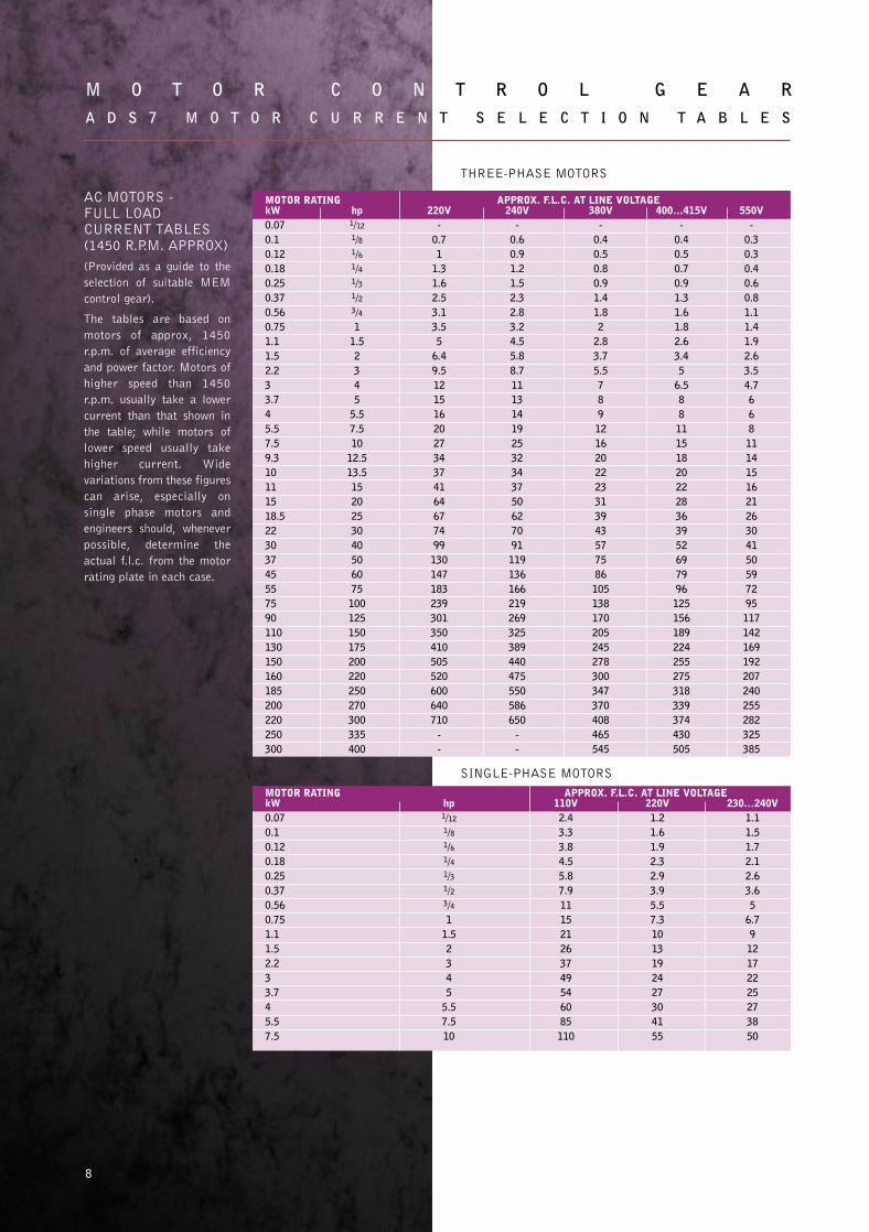
AC MOTORS - FULL LOAD CURRENT TABLES(1450 R.P.M. APPROX)
(Provided as a guide to the
selection of suitable MEM
control gear).
The tables are based on
motors of approx, 1450
r.p.m. of average efficiency
and power factor. Motors of
higher speed than 1450
r.p.m. usually take a lower
current than that shown in
the table; while motors of
lower speed usually take
higher current. Wide
variations from these figures
can arise, especially on
single phase motors and
engineers should, whenever
possible, determine the
actual f.l.c. from the motor
rating plate in each case.
THREE-PHASE MOTORS
MOTOR RATING APPROX. F.L.C. AT LINE VOLTAGEkW hp 220V 240V 380V 400...415V 550V0.07 1/12 - - - - -0.1 1/8 0.7 0.6 0.4 0.4 0.30.12 1/6 1 0.9 0.5 0.5 0.30.18 1/4 1.3 1.2 0.8 0.7 0.40.25 1/3 1.6 1.5 0.9 0.9 0.60.37 1/2 2.5 2.3 1.4 1.3 0.80.56 3/4 3.1 2.8 1.8 1.6 1.10.75 1 3.5 3.2 2 1.8 1.41.1 1.5 5 4.5 2.8 2.6 1.91.5 2 6.4 5.8 3.7 3.4 2.62.2 3 9.5 8.7 5.5 5 3.53 4 12 11 7 6.5 4.73.7 5 15 13 8 8 64 5.5 16 14 9 8 65.5 7.5 20 19 12 11 87.5 10 27 25 16 15 119.3 12.5 34 32 20 18 1410 13.5 37 34 22 20 1511 15 41 37 23 22 1615 20 64 50 31 28 2118.5 25 67 62 39 36 2622 30 74 70 43 39 3030 40 99 91 57 52 4137 50 130 119 75 69 5045 60 147 136 86 79 5955 75 183 166 105 96 7275 100 239 219 138 125 9590 125 301 269 170 156 117110 150 350 325 205 189 142130 175 410 389 245 224 169150 200 505 440 278 255 192160 220 520 475 300 275 207185 250 600 550 347 318 240200 270 640 586 370 339 255220 300 710 650 408 374 282250 335 - - 465 430 325300 400 - - 545 505 385
SINGLE-PHASE MOTORS
MOTOR RATING APPROX. F.L.C. AT LINE VOLTAGEkW hp 110V 220V 230...240V0.07 1/12 2.4 1.2 1.10.1 1/8 3.3 1.6 1.50.12 1/6 3.8 1.9 1.70.18 1/4 4.5 2.3 2.10.25 1/3 5.8 2.9 2.60.37 1/2 7.9 3.9 3.60.56 3/4 11 5.5 50.75 1 15 7.3 6.71.1 1.5 21 10 91.5 2 26 13 122.2 3 37 19 173 4 49 24 223.7 5 54 27 254 5.5 60 30 275.5 7.5 85 41 387.5 10 110 55 50
29182 MEM MotorControlGear new 30/7/02 10:54 Page 11

9
A D S 7 S H O R T C I R C U I T C O - O R D I N A T I O N
The back up fuses quoted in this catalogue give type 2 co-ordination as defined in
BSEN 60947-4-1 up to 80kA prospective @ 415V 3ph.
In selected cases it is possible to use Memshield 2 miniature circuit breakers to
provide similar back up protection for automatic starters.
STARTER TYPE OVERLOAD RELAY BACK-UP PROTECTIONMAX. HRC MEMSHIELD 2 MCBS
CURRENT FUSE, MEMRANGE A ‘S’ TYPE, A TYPE C TYPE D
Direct-on-line 0.15 - 0.22 2 MCH306 MDH306
380 ... 415V 0.22 - 0.33 2 MCH306 MDH306
3-phase 0.33 - 0.50 2 MCH306 MDH306
0.50 - 0.74 4 MCH306 MDH306
0.74 - 1.11 6 MCH306 MDH306
1.11 - 1.66 6 MCH306 MDH306
1.66 - 2.50 10 MCH306 MDH306
2.50 - 3.70 16 MCH310 MDH306
3.70 - 5.60 20 MCH316 MDH310
5.60 - 8.40 20M25 MCH320 MDH316
8.40 - 11.90 20M32 MCH320 MDH320
11.40 - 16.00 32M40 MCH340 MDH332
16.00 - 23.00 32M50 MCH340 MDH332
23.00 - 33.0 63M80 MCH363 MDH340
Direct-on-line 0.74 - 1.11 6 MCH106 MDH106
220 ... 240V 1.11 - 1.66 6 MCH106 MDH106
single phase 1.66 - 2.50 10 MCH110 MDH106
2.50 - 3.70 16 MCH110 MDH106
3.70 - 5.60 20 MCH116 MDH110
5.60 - 8.40 20M25 MCH120 MDH116
8.40 - 11.90 20M32 MCH132 MDH120
11.40 - 16.00 32M40 MCH150 MDH132
Star-Delta 4.80 - 6.40 16 MCH310 MDH310
380 ... 415V 6.40 - 9.70 20 MCH316 MDH316
3-phase 9.70 - 14.50 20M25 MCH320 MDH320
14.50 - 20.60 20M32 MCH340 MDH332
19.70 - 27.70 32M40 MCH350 MDH332
26.00 - 42.00 32M63 MCH363 -
38.00 - 57.00 63M80 - -
Current range must be selected to include actual motor rated full load current.
Typical operating characteristic curves for MEM contactor starters are
reproduced on page 10.
29182 MEM MotorControlGear new 30/7/02 10:54 Page 12
10
M O T O R C O N T R O L G E A RA D S 7 T Y P I C A L O P E R A T I N G C H A R A C T E R I S T I C S
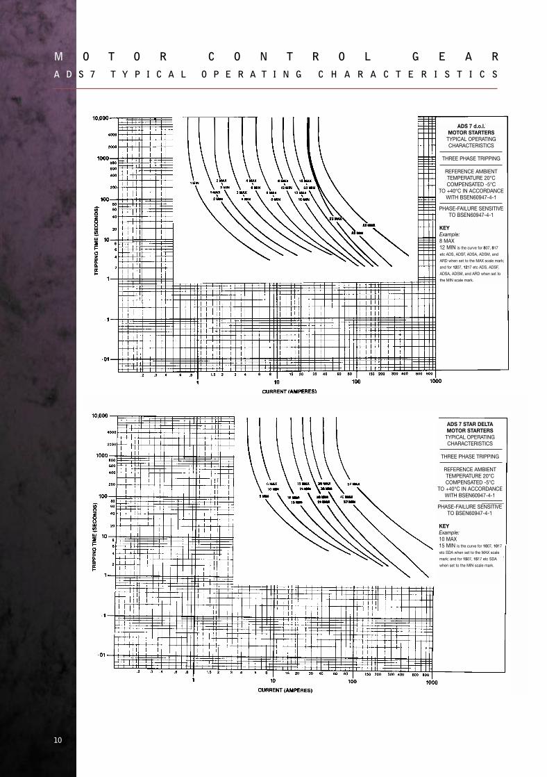
ADS 7 STAR DELTAMOTOR STARTERS
TYPICAL OPERATINGCHARACTERISTICS
THREE PHASE TRIPPING
REFERENCE AMBIENTTEMPERATURE 20°CCOMPENSATED -5°C
TO +40°C IN ACCORDANCEWITH BSEN60947-4-1
PHASE-FAILURE SENSITIVETO BSEN60947-4-1
KEYExample:10 MAX15 MIN is the curve for 1007, 1017
etc SDA when set to the MAX scale
mark; and for 1507, 1517 etc SDA
when set to the MIN scale mark.
ADS 7 d.o.l.MOTOR STARTERS
TYPICAL OPERATINGCHARACTERISTICS
THREE PHASE TRIPPING
REFERENCE AMBIENTTEMPERATURE 20°CCOMPENSATED -5°C
TO +40°C IN ACCORDANCEWITH BSEN60947-4-1
PHASE-FAILURE SENSITIVETO BSEN60947-4-1
KEYExample:8 MAX12 MIN is the curve for 807, 817
etc ADS, ADSF, ADSA, ADSM, and
ARD when set to the MAX scale mark;
and for 1207, 1217 etc ADS, ADSF,
ADSA, ADSM, and ARD when set to
the MIN scale mark.
29182 MEM MotorControlGear new 30/7/02 10:54 Page 13

11
A D S 7 D I M E N S I O N S
D.O.L. metaclad - surface mounting List Nos. 27ADS1X-47ADS2X(Details in brackets refer to 27ADS3X-47ADS3X)
Enclosures List Nos. 331VCE, 331 VSEL/R (Details in brackets refer to
4VCE, 441VSEL/R)
D.O.L. moulded - surface mounting List Nos. 27-47ADSM1X, 27-47ADSM2X
29182 MEM MotorControlGear new 30/7/02 10:54 Page 14

12
M O T O R C O N T R O L G E A RA D S 7 D I M E N S I O N S
D.O.L. metalclad-surface mounting with switch-disconnector
List Nos. 27ADSA1X-47ADSA2X (Details in brackets refer to 27ADSA3X-47ADSA3X)
Enclosures List Nos. 331VSELA/RA
D.O.L. metalclad-surface mounting, two-direction List Nos. 27-47ARD2X (Details in brackets refer
to 27ARD3X-47ARD3X)
Enclosures List No. 331VREML
Star-Delta metalclad-surface mounting, List Nos. 27-47SDA2X (Details in brackets refer
to 27-47SDA3X)
Star-Delta metalclad-surface mounting with switch-disconnector, List Nos. 27-47SDAA2X, 27-47SDAA3X
29182 MEM MotorControlGear new 30/7/02 10:54 Page 15

13
A D S 7 T Y P I C A L C I R C U I T D I A G R A M S
NOTES TO STARTER DIAGRAMS
Coil Phase to Neutral:- remove connector Y, connect Neutral to a1.
Separate Coil Supply:- remove connectors Y and Z, connect coil supply to a1 and 95.
Coil Voltage:- Ensure correct voltage coil is fitted for separate coil supply and phase to neutral
applications.
External Interlock:- Remove connection Z and insert interlock between 1 and 95.
Alarm Circuit:- A trip alarm signal voltage equal to the coil voltage is available between 98 and a1. The
switch is rated at 440VA, 500V maximum.
CONTROL CIRCUIT FUSES (10A MAX).
Coil Connected Phase to Neutral (1 fuse):- remove connector Z and connect fuse between 1 and 95.
Coil Connected Phase to Phase (2 fuses):- remove connector Z and connect fuse between 1 and 95.
Remove connector Y and connect fuse between 3 and a1.
NOTE:- the voltage rating of the fuse(s) must be suitable for the control circuit voltage.
SHORT CIRCUIT PROTECTION:- Maximum sizes of MEM back-up fuses together with appropriate mcb
ratings where applicable are tabulated on page 9.
TO REVERSE DIRECTION OF ROTATION (3-Phase Motors):- Interchange any two motor lines 2, 4 or 6.
DIRECT-ON-LINE, 11KW MAX, METALCLAD/MOULDED
29182 MEM MotorControlGear new 30/7/02 10:55 Page 16

14
M O T O R C O N T R O L G E A RA D S 7 T Y P I C A L C I R C U I T D I A G R A M S
NOTES TO STARTER DIAGRAMS
COIL CONNECTIONS
For 380/415V Coils:- the starter is supplied with control circuit connected between L1 and L2.
For 220/240V Coils:- the starter is supplied with control circuit connected between L1 and N.
SEPARATE COIL SUPPLY
Phase to Neutral applications:- remove connectors Z and Y, link a1 to N via connector Y, and connect supply to 95 and N.
Phase to Phase applications:- remove connectors z and Y, and connect supply to a1 and 95.
COIL VOLTAGE - Ensure correct voltage coil is fitted in phase to neutral and separate coil supply applications.
EXTERNAL INTERLOCK - Remove connection Z and insert interlock between 1 and 95.
ALARM CIRCUIT - At trip an alarm signal voltage equal to the coil voltage is available between 98 and a1.
CONTROL CIRCUIT FUSES
Coil Connected Phase to Neutral (1 fuse):- remove connectors Z and Y, link a1 to N via connector Y, and connect fuse between 1 and 95.
Coil Connected Phase to Phase (2 fuses):- remove connector Z and connect fuse between 1 and 95. Remove connector Y and connect
fuse between 3 and a1.
NOTE:- the voltage rating of the fuse(s) must be suitable for the control circuit voltage.
Single Phase load - Connect supply to 1 and 3, connect load to 2 and 6, and insert a cable of cross-sectional area equal to the supply
cables between 4 and 5.
SHORT CIRCUIT PROTECTION:- Maximum sizes of MEM back-up fuses together with appropriate
mcb ratings where applicable are tabulated on page 9.
TO REVERSE DIRECTION OF ROTATION - Interchange any two motor lines 2, 4 or 6.
DIRECT-ON-LINE, 15KW MAX, METALCLAD
D.O.L. STARTER WITH SWITCH-DISCONNECTOR 3-WIRE (PUSH-BUTTON)CONTROL LOCAL
29182 MEM MotorControlGear new 30/7/02 10:55 Page 17

15
A D S 7 T Y P I C A L C I R C U I T D I A G R A M S
DIRECT-ON-LINE, 11KW MAX, WITH SWITCH-DISCONNECTOR FITTED. METALCLAD
NOTES TO STARTER DIAGRAMS
Coil Phase to Neutral:- remove connector Y, connect Neutral to a1.
SEPARATE COIL SUPPLY:- remove connectors Y and Z, connect coil supply to a1 and 95.
COIL VOLTAGE:- Ensure correct voltage coil is fitted for separate coil supply and phase to neutral applications.
EXTERNAL INTERLOCK:- Remove connection Z and insert interlock between 1 and 95.
ALARM CIRCUIT:- A trip alarm signal voltage equal to the coil voltage is available between 98 and a1. The switch
is rated at 440VA, 500V maximum.
CONTROL CIRCUIT FUSES (10A MAX).
Coil Connected Phase to Neutral (1 fuse):- remove connector Z and connect fuse between 1 and 95.
Coil Connected Phase to Phase (2 fuses):- remove connector Z and connect fuse between 1 and 95. Remove
connector Y and connect fuse between 3 and a1.
NOTE:- the voltage rating of the fuse(s) must be suitable for the control circuit voltage.
SHORT CIRCUIT PROTECTION:- Maximum size of MEM back-up fuses together with appropriate mcb
ratings where applicable are tabulated on page 9.
TO REVERSE DIRECTION OF ROTATION (3-Phase Motors):- Interchange any two motor lines 2, 4 or 6.
29182 MEM MotorControlGear new 30/7/02 10:55 Page 18

16
M O T O R C O N T R O L G E A RA D S 7 T Y P I C A L C I R C U I T D I A G R A M S
NOTES TO STARTER DIAGRAMS
COIL CONNECTIONSFor 380/415V Coils:- the starter is supplied with control circuit connected between L1 and L2.
For 220/240V Coils:- the starter is supplied with control circuit connected between L1 and N.
SEPARATE COIL SUPPLYPhase to Neutral applications:- remove connectors Z and Y, link a1 to N via connector Y, and connect supply to 95 and N.
Phase to Phase applications:- remove connectors Z and Y, and connect supply to a1 and 95.
COIL VOLTAGE:- Ensure correct voltage coil is fitted in phase to neutral and separate coil supply applications.
EXTERNAL INTERLOCK:- Remove connection Z and insert interlock between 1 and 95.
ALARM CIRCUIT:- At trip an alarm signal voltage equal to the coil voltage is available between 98 and a1.
CONTROL CIRCUIT FUSES
Coil Connected Phase to Neutral (1 fuse):- remove connectors Z and Y, link a1 to N via connector Y, and connect fuse between 1 and 95.
Coil Connected Phase to Phase (2 fuses):- remove connector Z and connect fuse between 1 and 95. Remove connector Y and connect
fuse between 3 and a1.
NOTE:- the voltage rating of the fuse(s) must be suitable for the control circuit voltage.
SINGLE PHASE LOAD - Connect supply to 1 and 3, connect load to 2 and 6, and insert a cable of cross-sectional area equal to the supply
cables between 4 and 5.
SHORT CIRCUIT PROTECTION:Maximum sizes of MEM back-up fuses together with appropriate mcb ratings where applicable are
tabulated on page 9.
TO REVERSE DIRECTION OF ROTATION - Interchange any two motor lines 2, 4 or 6.
DIRECT-ON-LINE, 15KW MAX, WITH SWITCH-DISCONNECTOR FITTED. METALCLAD
29182 MEM MotorControlGear new 30/7/02 10:55 Page 19

17
A D S 7 T Y P I C A L C I R C U I T D I A G R A M S
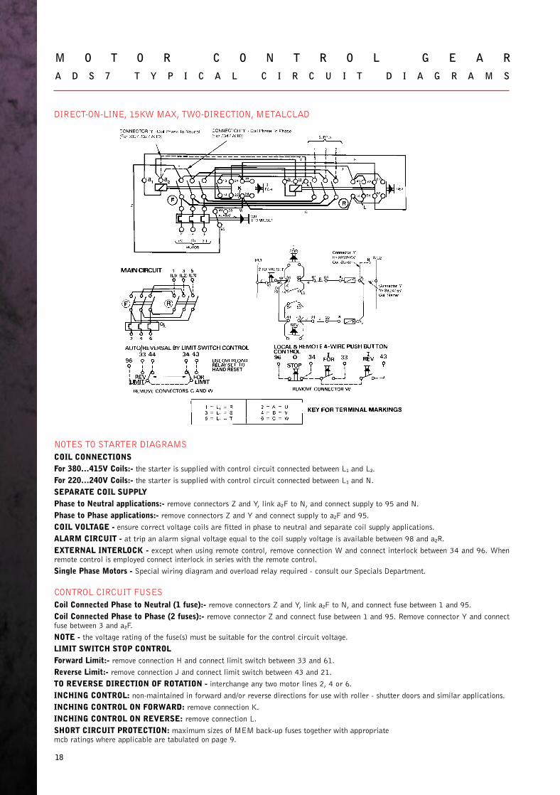
DIRECT-ON-LINE, 11KW MAX, TWO-DIRECTION, METALCLAD
NOTES TO STARTER DIAGRAMS
COIL PHASE TO NEUTRAL - remove connection Y and connect Neutral to a1F.
SEPARATE COIL SUPPLY - remove connections Y and Z and connect coil supply to a1F and 95.
COIL VOLTAGE - ensure correct voltage coil is fitted in phase to neutral and separate coil supply applications.
EXTERNAL INTERLOCK - except when using remote control remove connection W and connect interlock
between 34 and 96. When remote control is employed connect interlock in series with the remote control.
TO REVERSE DIRECTION OF ROTATION - interchange any two supply lines 1, 3 or 5.
SHORT CIRCUIT PROTECTION - maximum sizes of MEM back-up fuses together with appropriate mcb
ratings where applicable are tabulated on page 9.
LIMIT SWITCH STOP CONTROL:-
Forward limit - remove connection H and connect limit switch between 13 and 51.
Reverse limit - remove connection J and connect limit switch between 43 and 21.
ALARM CIRCUIT - at trip an alarm signal voltage equal to the coil supply voltage is available between 98 and
a1R.
CONTROL CIRCUIT FUSES:-Coil phase to neutral (one fuse) - remove connection Z and connect fuse between 1 and 95.
Coil phase to phase (two fuses) - remove connection Z and connect fuse between 1 and 95. Remove
connection Y and connect fuse between 3 and a1F.
NOTE: The voltage rating of the fuse(s) must be suitable for the control circuit voltage.
INCHING CONTROL - non-maintained in forward and/or reverse directions for use with roller-shutter doors
and similar applications.
INCHING CONTROL ON FORWARD - remove connection K.
INCHING CONTROL REVERSE - remove connection L.
13 43 13 43
29182 MEM MotorControlGear new 30/7/02 10:55 Page 20
18
M O T O R C O N T R O L G E A RA D S 7 T Y P I C A L C I R C U I T D I A G R A M S
NOTES TO STARTER DIAGRAMS
COIL CONNECTIONSFor 380...415V Coils:- the starter is supplied with control circuit connected between L1 and L2.
For 220...240V Coils:- the starter is supplied with control circuit connected between L1 and N.
SEPARATE COIL SUPPLYPhase to Neutral applications:- remove connectors Z and Y, link a2F to N, and connect supply to 95 and N.
Phase to Phase applications:- remove connectors Z and Y and connect supply to a2F and 95.
COIL VOLTAGE - ensure correct voltage coils are fitted in phase to neutral and separate coil supply applications.
ALARM CIRCUIT - at trip an alarm signal voltage equal to the coil supply voltage is available between 98 and a2R.
EXTERNAL INTERLOCK - except when using remote control, remove connection W and connect interlock between 34 and 96. Whenremote control is employed connect interlock in series with the remote control.
Single Phase Motors - Special wiring diagram and overload relay required - consult our Specials Department.
CONTROL CIRCUIT FUSES
Coil Connected Phase to Neutral (1 fuse):- remove connectors Z and Y, link a2F to N, and connect fuse between 1 and 95.
Coil Connected Phase to Phase (2 fuses):- remove connector Z and connect fuse between 1 and 95. Remove connector Y and connectfuse between 3 and a2F.
NOTE - the voltage rating of the fuse(s) must be suitable for the control circuit voltage.
LIMIT SWITCH STOP CONTROLForward Limit:- remove connection H and connect limit switch between 33 and 61.
Reverse Limit:- remove connection J and connect limit switch between 43 and 21.
TO REVERSE DIRECTION OF ROTATION - interchange any two motor lines 2, 4 or 6.
INCHING CONTROL: non-maintained in forward and/or reverse directions for use with roller - shutter doors and similar applications.
INCHING CONTROL ON FORWARD: remove connection K.
INCHING CONTROL ON REVERSE: remove connection L.
SHORT CIRCUIT PROTECTION: maximum sizes of MEM back-up fuses together with appropriatemcb ratings where applicable are tabulated on page 9.
DIRECT-ON-LINE, 15KW MAX, TWO-DIRECTION, METALCLAD
29182 MEM MotorControlGear new 30/7/02 11:23 Page 21
19
A D S 7 T Y P I C A L C I R C U I T D I A G R A M S
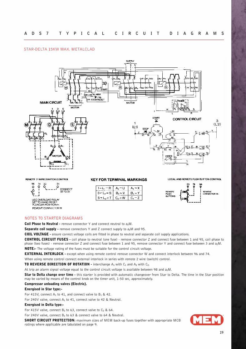
STAR-DELTA 15KW MAX. METALCLAD
NOTES TO STARTER DIAGRAMS
Coil Phase to Neutral - remove connector Y and connect neutral to a2M.
Separate coil supply - remove connectors Y and Z connect supply to a2M and 95.
COIL VOLTAGE - ensure correct voltage coils are fitted in phase to neutral and separate coil supply applications.
CONTROL CIRCUIT FUSES - coil phase to neutral (one fuse) - remove connector Z and connect fuse between 1 and 95, coil phase tophase (two fuses) - remove connector Z and connect fuse between 1 and 95, remove connector Y and connect fuse between 3 and a2M.
NOTE:- The voltage rating of the fuses must be suitable for the control circuit voltage.
EXTERNAL INTERLOCK - except when using remote control remove connector W and connect interlock between 96 and 74.
When using remote control connect external interlock in series with remote 2 wire (switch) control.
TO REVERSE DIRECTION OF ROTATION - interchange A1 with C1 and A2 with C2.
At trip an alarm signal voltage equal to the control circuit voltage is available between 98 and a2M.
Star to Delta change over time - this starter is provided with automatic changeover from Star to Delta. The time in the Star positionmay be varied by means of the control knob on the timer unit, 1-50 sec, approximately.
Compressor unloading valves (Electric).Energised in Star type:-For 415V, connect A1 to 41, and connect valve to B1 & 42.
For 240V valve, connect A1 to 41, connect valve to 42 & Neutral.
Energised in Delta type:-For 415V valve, connect B2 to 63, connect valve to C2 & 64.
For 240V valve, connect B2 to 63 & connect valve to 64 & Neutral.
SHORT CIRCUIT PROTECTION: maximum sizes of MEM back-up fuses together with appropriate MCB ratings where applicable are tabulated on page 9.
29182 MEM MotorControlGear new 30/7/02 11:23 Page 22

20
M O T O R C O N T R O L G E A RA D S 7 T Y P I C A L C I R C U I T D I A G R A M S
COIL CONNECTIONS
For 380...415V Coils:- the starter is supplied with control circuit connected between L1 and L2 with a control fuse in each phase.
For 220...240V Coils:- the starter is supplied with control circuit connected between L1 and N with one fuse connected in the phase circuit.
SEPARATE COIL SUPPLYPhase to Neutral applications (1 fuse):- remove connectors Z and X, link a2 to N via connector Y, and connect supply to F2 and N.
Phase to Phase applications (2 fuses):- remove connectors Z and X, link a2 to F1 and connect supply to F2 and 43.
NOTE - the voltage rating of the fuse(s) must be suitable for the control circuit voltage.
COIL VOLTAGE - ensure correct voltage coils are fitted in phase to neutral and separate coil supply applications.
EXTERNAL INTERLOCK - except when using remote control, remove connector W and connect interlock between 96 and 74. Whenusing remote control, connect external interlock in series with remote 2 wire (switch) control.
TO REVERSE DIRECTION OF ROTATION - interchange A1 with C1 and A2 with C2.
ALARM CIRCUIT - at trip an alarm signal voltage equal to the control circuit voltage is available between 98 and a2M.
STAR TO DELTA CHANGEOVER TIME - this starter is provided with automatic changeover from Star to Delta. The time in the Starposition may be varied by means of the control knob on the timer unit, 1 - 50 secs. approximately.
Compressor unloading valves (Electric).
Energised in Star type:- For 415V valve, connect A1 to 51, and connect valve to B1 & 52. For 240V valve, connect A1 to 51 and connectvalve to 52 & Neutral.
Energised in Delta type:- For 415V valve, connect valve to B2 & C2.
For 240V valve, connect valve to B2 and Neutral.
SHORT CIRCUIT PROTECTION:- maximum sizes of MEM back-up fuses together with appropriateMCB ratings where applicable are tabulated on page 9.
STAR-DELTA 30KW MAX. METALCLAD
29182 MEM MotorControlGear new 30/7/02 11:23 Page 23

21
A D S 7 E N C L O S E D I N D U S T R I A L S T A R T E R S3 - P H A S E D . O . L . A N D S T A R - D E L T A ,T Y P E D S B A N D Y S B , 9 0 K W M A X , I P 5 5
MEM’s heavy duty industrial starters have been developed to increase
the range of enclosed starters up to 90kW.
The design profile and numerous optional features available have been
developed from experience of user requirements. Thus the starters will
satisfy most specifications and are designed for mounting above or below
busbar chambers to form part of a switchboard assembly if required.
This range complements the lower rated ADS7 motor starters listed on
page 4.
SPECIFICATIONMEM enclosed starters comply with BSEN 60947-4-1,
IEC 60947-4-1 and VDE 0660 and have provisions for TP
interlocked and switch disconnectors HRC main fuses. Start and
Stop pushbuttons, control circuit fuses, remote control terminal
block and overload relays are fitted as standard.
ENCLOSURESEnclosures are robust rust-protected sheet steel with fully
gasketed hinged covers having environmental protection of IP55
to BSEN 60529: 1992 and IEC 60529: 1976. Switch -
disconnector versions IP54 except to special order.
CONTACTORSModern block-type complying with BSEN 60947-4-1, IEC 60947-4-1 and
VDE 0660. Each having provision for accepting additional auxiliary
contacts.
OVERLOAD RELAYSThe starters are supplied with an appropriate ambient temperature
compensated phase-failure-sensitive thermal relay.
SWITCH-DISCONNECTORSThe interlocked stalled-motor complete with padlocking switch-
disconnectors facility are available with provisions for auxiliary poles.
They are type tested to BSEN 60947-3 Category AC23 and provide a
means of isolation and switching for mechanical maintenance in
accordance with the 16th Edition of the IEE wiring regulations.
HRC FUSESProvisions for S-type ASTA-certified HRC fuse links to BS 88 Part 2:
1975 and complying with IEC 60269 Parts 1 & 2 are available in
addition to the TP interlocked switch-disconnector.
OPERATING CONDITIONS-5ºC to +40ºC.
OPTIONAL FEATURES AVAILABLEMotor rated ammeter with suppressed scale to indicate starting peaks.
Low voltage control circuit transformer.
Isolator auxiliary poles for separate control circuit supply.
Pilot indicating lamps.
Hand/Off/Auto or Local/Off/Remote selector switch.
Higher ratings up to 200kW available on request.
SPECIALS - see page 36
Reversing starters.
Two-speed starters for dual or tapped-wound motors.
Stator and rotor starters.
Main/Standby starters.
29182 MEM MotorControlGear new 30/7/02 11:23 Page 24

22
A D S 7 E N C L O S E D I N D U S T R I A L S T A R T E R S3 - P H A S E D . O . L . A N D S T A R - D E L T A ,T Y P E D S B A N D Y S B , 9 0 K W M A X , I P 5 5
ORDER REFERENCES
MAX. FLC, 400 ... 415V 3ph LIST NO. OF BASIC ENCLOSED STARTER LESS SWITCH - DISCONNECTORA MAXIMUM AND HRC FUSES ACCORDING TO COIL VOLTAGE, 50Hz.
kW hp OVERLOAD RELAY FITTED.CONTROL VOLTAGES OTHER THAN THOSE LISTED ARE
AVAILABLE TO SPECIAL ORDER.
230 ... 240V 400 ... 415V
D.O.L. starter
46 22 30 522DSB* 722DSB*
63 30 40 530DSB* 730DSB*
75 37 50 537DSB* 737DSB*
110 55 75 555DSB* 755DSB*
180 90 125 590DSB* 790DSB*
Star-delta starter
57 30 40 530YSB* 730YSB*
80 45 60 545YSB* 745YSB*
110 55 75 555YSB* 755YSB*
138 75 100 575YSB* 775YSB*
180 90 125 590YSB* 790YSB*
*Add suffix ‘A’ to List No. for starter with switch-disconnector ie. 722DSBAAdd suffix ‘H’ to List No. for starter with switch-disconnector-fuse including
HRC main fuses ie. 790YSBH
DIMENSIONS
STARTER TYPE H W D
D.O.L. starters22, 30 DSB 300 200 180
37 DSB 400 300 180
22, 30 DSBA, H 500 300 180
37 DSBA, H600 400 220
55, 90 DSB
55, 90 DSBA, H 700 400 220
Star-delta starters
30 YSB 400 300 180
30 YSBA, H400 400 180
45, 55, 75 YSB
45, 55, 75 YSBA600 400 220
45, 55 YSBH
75 YSBH, 90 YSB 700 500 220
90 YSBA, H 800 600 220
29182 MEM MotorControlGear new 30/7/02 11:23 Page 25

23
M S U P U S H B U T T O N C O N T R O L U N I T S ( M O U L D E D I P 6 5 )
The MSU series of pushbutton control units has been designed to match
MEM’s ADS7 motor starter range. Simplicity, versatility and robust
construction have been successfully allied to attractive styling.
One, two and three button types are available in a variety of
configurations. 3-button types 23MSU and 23MSU/L are
supplied with a fitted front label reading FORWARD,
REVERSE, STOP. A separate loose label is provided for
situations requiring UP, DOWN, STOP.
21MSUML emergency stop units conform to clause 6.2.3 of
BS4163 - Workshop emergency stop systems (schools and
similar establishments).
CONTACT BLOCKSEach contact block comprises 1 - N/O and 1 - N/C contact.
OPERATIONStart units are push to make (N/O).
Stop units are push to break (N/C). The latching device where fitted
holds the stop pushbutton in the depressed position until the latch is
released by clockwise rotation of the mushroom head.
PERFORMANCE RATINGMSU pushbuttons comply with:- BSEN 60947-5-1: 1992,
IEC 60947-5-1: 1990. 6A, 415V AC. Utilisation category AC-15. One
‘a’ contact + one ‘b’ contact per way. Form Za Uimp = 6kV.
STOP, Latching pattern units comply with BSEN 60947-5-5:1998,
IEC 60947-5-:1998
ENCLOSURESCovers are tough polycarbonate while bases are glass-filled polycarbonate.
Standard protection is IP65. The enclosure material is resistant to diluted
mineral and organic acids. 20mm conduit knockouts complete with M20
conduit threads are incorporated at top and bottom. Single way enclosures
may be turned through 90º to permit side cable entry.
Flame resistance to UL94:VO.
Ambient temperature rating -5ºC to +40ºC.
TERMINAL CABLE CAPACITIESSwitch and earth terminals 2 x 1mm2 - 2.5mm2 rigid, 2 x 1.5mm2 -
2.5mm2 flexible.
Single way control stations are also readily available with a range of
22mm cover mounted control and indicating devices. In addition to
those listed other 22mm devices may be supplied to special order.
29182 MEM MotorControlGear new 30/7/02 11:24 Page 26

24
M O T O R C O N T R O L G E A RM S U P U S H B U T T O N C O N T R O L U N I T S ( M O U L D E D I P 6 5 )
NO. OF BUTTONS DESCRIPTION LIST NO.
1 START 21MSSU
1 STOP 21MSU
1 STOP, latching pattern 21MSUL(push to latch, turn to release)
1 STOP (50mm dia. mushroom head) 21MSUM
1 STOP, latching pattern - 21MSUML(push to latch, turn to release)(50mm dia. mushroom head)
2 START-STOP 22MSU
2 START-LATCH STOP/RESET 22MSUL
3 FORWARD-REVERSE-STOP 23MSU(Alternative label: UP-DOWN-STOP)
3 FORWARD-REVERSE-LATCH STOP/RESET 23MSUL(Alternative label: UP-DOWN-STOP)
MSU DIMENSIONSSINGLE WAY CONTROL STATIONS INCORPORATING 22mm CONTROL DEVICES LIST NO.Mushroom head latch stop, key release
with 1-N/C contact 21MSULK
Two position key operated selector switch with
1-N/O contact labelled 0/1 (Key removable in
both positions) 21MSU2K
Two position key operated spring return to “off”
selector switch with 1-N/O and 1-N/C contact
labelled 0/1 (Key removable in off position) 21MSU2SK
SPARE SWITCH UNIT (NOT SUITABLE FOR 22mm DEVICES) LIST NO.
Complete replacement unit with
N/O and N/C contacts and fixing screw 21MSB
21 MSU21 MSU/L/M/ML
22 MSU22 MSU/L
23 MSU23 MSU/L
29182 MEM MotorControlGear new 30/7/02 11:24 Page 27
25
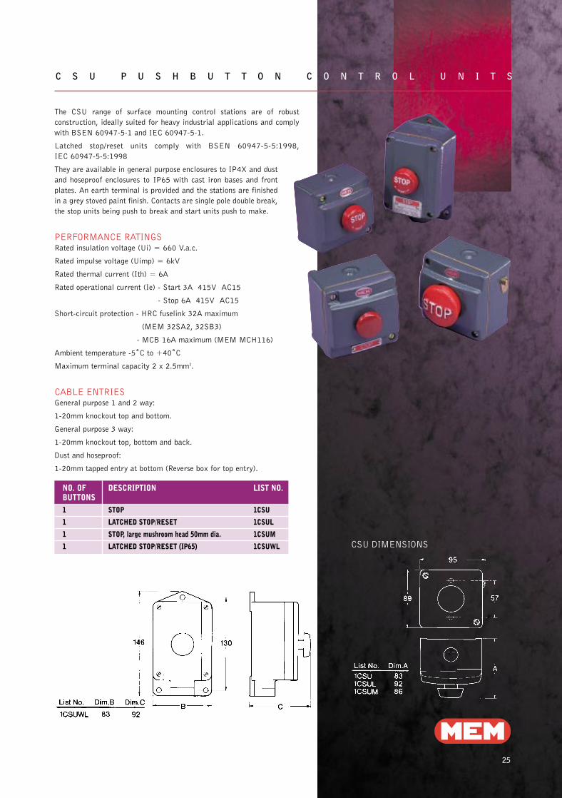
C S U P U S H B U T T O N C O N T R O L U N I T S
CSU DIMENSIONS
The CSU range of surface mounting control stations are of robust
construction, ideally suited for heavy industrial applications and comply
with BSEN 60947-5-1 and IEC 60947-5-1.
Latched stop/reset units comply with BSEN 60947-5-5:1998,
IEC 60947-5-5:1998
They are available in general purpose enclosures to IP4X and dust
and hoseproof enclosures to IP65 with cast iron bases and front
plates. An earth terminal is provided and the stations are finished
in a grey stoved paint finish. Contacts are single pole double break,
the stop units being push to break and start units push to make.
PERFORMANCE RATINGSRated insulation voltage (Ui) = 660 V.a.c.
Rated impulse voltage (Uimp) = 6kV
Rated thermal current (Ith) = 6A
Rated operational current (Ie) - Start 3A 415V AC15
- Stop 6A 415V AC15
Short-circuit protection - HRC fuselink 32A maximum
(MEM 32SA2, 32SB3)
- MCB 16A maximum (MEM MCH116)
Ambient temperature -5˚C to +40˚C
Maximum terminal capacity 2 x 2.5mm2.
CABLE ENTRIESGeneral purpose 1 and 2 way:
1-20mm knockout top and bottom.
General purpose 3 way:
1-20mm knockout top, bottom and back.
Dust and hoseproof:
1-20mm tapped entry at bottom (Reverse box for top entry).
NO. OF DESCRIPTION LIST NO.BUTTONS1 STOP 1CSU
1 LATCHED STOP/RESET 1CSUL
1 STOP, large mushroom head 50mm dia. 1CSUM
1 LATCHED STOP/RESET (IP65) 1CSUWL
29182 MEM MotorControlGear new 30/7/02 11:24 Page 28

26
L O C A L D I S C O N N E C T O R SLO C A L D I S C O N N E C T O R S S TA N D A R D D U T Y, T Y P E R D M P, 2 0 - 6 3 A , I P 6 5 , 2 - 8 P O L E S
NOMINAL OPERATIONAL OPERATIONAL RATED RATED CONDITIONAL MAX DEGREE OFUNIT CURRENT, Ie AND CURRENT, Ie AND SHORT TIME SHORT CIRCUIT TERMINAL PROTECTIONRATING POWER, 415V POWER, 660V WITHSTAND CURRENT CAPACITYIe CATEGORY: CATEGORY: CURRENT (PROSPECTIVE R.M.S. mm2
RMS FOR AMPS AT 415V AC, FUSED)AC21 AC23 AC21 AC23 1 SEC Icw kA FUSE RATING
20A 20A 5.5kW 20A 5.5kW 0.25kA 25 20A 1 x 4mm2 IP6550 16A 2 x 2.5mm2
25A 25A 7.5kW 25A 7.5kW 0.40kA 25 25A 1 x 6mm2 IP6550 20A 2 x 4mm2
40A 40A 15kW 40A 15kW 0.80kA 62 40A 1 x 10mm2 IP652 x 6mm2
63A 63A 22kW 63A 18.5kW 1.70kA 50 63A 1 x 16mm2 IP652 x 10mm2
Auxiliary contact rating as main poles.
DIMENSIONS (MM)
NOMINAL A B C C D E F G H RUNIT 2-4 POLE 6 POLE ISORATING, Ie 20 & 40A 20 & 40A THREAD
2-3 POLE 4-6 POLE 25 & 63A 25 & 63A
20 and 25A 90 90 71 98 30 79 63 30 4.5 2 x 2040 and 63A 176 125 85 119 36 146 112 68 5.5 2 x 25
1 x 16
ORDER REFERENCES
NOMINAL UNIT DOUBLE POLE TRIPLE POLE FOUR POLE FOUR POLE SIX POLE EIGHT POLERATING, Ie AND NEUTRAL AND NEUTRAL LIST NO. AND NEUTRAL AND NEUTRAL LIST NO.
LIST NO. LIST NO. LIST NO. LIST NO.20A 2021RDMP 2031RDMP 204RDMP 2041RDMP 2061RDMP -
25A 2521RDMP 2531RDMP 254RDMP 2541RDMP 2561RDMP 258RDMP
40A 4021RDMP 4031RDMP 404RDMP 4041RDMP 4061RDMP -
63A 6321RDMP 6331RDMP 634RDMP 6341RDMP 6361RDMP 638RDMP
NB:- Switches with additional poles are available on request.
TECHNICAL DATA
Complying with BSEN60947 and IEC 408 the RDMP range of rotary
cam switches are suitable for on load switching of general distribution a.c.
power circuits and infrequent duty motor isolation.
Grey, moulded thermoplastic enclosures provide protection to
IP65 making them suitable for most indoor and outdoor
environmental conditions.
These compact isolators are fitted with red/yellow operating handles
padlockable in the ‘OFF’ position with up to three padlocks.
Units supplied with an early break auxiliary contact are indicated by a
figure 1 in the list number e.g. 2021RDMP.
The enclosure design allows easy access for cabling. Solid neutral and
earth termination points are a standard feature.
29182 MEM MotorControlGear new 30/7/02 11:25 Page 29

2727
LO C A L D I S C O N N E C T O R S S TA N D A R D D U T Y, T Y P E R D M P, 2 0 - 6 3 A , I P 6 5 , 2 - 8 P O L E S
Complying with BSEN60947 and IEC 408 the PC2 range
of rotary cam isolating switches are suitable for on load
switching of general distribution A.C. power circuits and
infrequent duty motor isolation.
Grey, pressed steel enclosures provide protection to IP55.
These compact disconnectors are fitted with black
operating handles, padlockable in the ‘OFF’ position.
The enclosure design allows easy access for cabling by
removal of the switch interior.
Switches with additional poles are available on request.
2 pole and 4 pole units have removable neutral links
included for SPN (from 2P) or TPN (from 4P) conversions.
Earth terminals provided as standard.
NOMINAL UNIT DOUBLE POLE TRIPLE POLE FOUR POLE SIX POLERATING, Ie LIST NO. LIST NO. LIST NO. LIST NO.20A PC2G20 2 PC2G20 3 PC2G20 4 PC2G20 6
25A PC2G25 2 PC2G25 3 PC2G25 4 PC2G25 6
40A PC2G40 2 PC2G40 3 PC2G40 4 PC2G40 6
63A PC2G63 2 PC2G63 3 PC2G63 4 PC2G63 6
NOMINAL OPERATIONAL OPERATIONAL RATED RATED CONDITIONAL MAX DEGREE OFUNIT CURRENT, Ie AND CURRENT, Ie AND SHORT TIME SHORT CIRCUIT TERMINAL PROTECTIONRATING POWER, 415V 3ph POWER, 660V 3ph WITHSTAND CURRENT CAPACITYIe CATEGORY: CATEGORY: CURRENT (PROSPECTIVE R.M.S.
RMS FOR AMPS AT 415V AC, FUSED)AC21 AC23 AC21 AC23 1 SEC kA FUSE RATING
20A 20A 5.5kW 20A 5.5kW 0.25kA 25 20A 1 x 4mm2 IP5550 16A 2 x 2.5mm2
25A 25A 7.5kW 25A 7.5kW 0.40kA 25 25A 1 x 6mm2 IP5550 20A 2 x 4mm2
40A 40A 15kW 40A 15kW 0.80kA 62 40A 1 x 10mm2 IP552 x 6mm2
63A 63A 22kW 63A 18.5kW 1.70kA 50 63A 1 x 16mm2 IP552 x 10mm2
PC2G20,
PC2G25,
PC2G40
(2P-6P)
TECHNICAL DATA
ORDER REFERENCES
DIMENSIONS
29182 MEM MotorControlGear new 30/7/02 11:25 Page 30