motor controller cmmp-as--m3 - festo usa · description exchangeand project conversion...
TRANSCRIPT

Description
Exchange and project
conversion
Motor controller
CMMP-AS-...-M3
as a replacement
device for
motor controller
CMMP-AS
8004593
1206NH
Motor controller
CMMP-AS-...-M3
CMMP-AS-...-M3
2 Festo – GDCP-CMMP-M3-RP-EN – 1206NH
Translation of the original instructions
GDCP-CMMP-M3-RP-EN
CANopen®, PROFINET®, PROFIBUS®, EtherNet/IP®, DeviceNet®, EtherCAT®, PHOENIX® are regis-
tered trademarks of the respective trademark owners in certain countries.
Identification of hazards and instructions on how to prevent them:
Warning
Hazards that can cause death or serious injuries.
Caution
Hazards that can cause minor injuries or serious material damage.
Other symbols:
Note
Material damage or loss of function.
Recommendations, tips, references to other documentation.
Essential or useful accessories.
Information on environmentally sound usage.
Text designations:
• Activities that may be carried out in any order.
1. Activities that should be carried out in the order stated.
– General lists.

CMMP-AS-...-M3
Festo – GDCP-CMMP-M3-RP-EN – 1206NH 3
Table of contents – CMMP-AS-...-M3
1 Introduction 6. . . . . . . . . . . . . . . . . . . . . . . . . . . . . . . . . . . . . . . . . . . . . . . . . . . . . . . . . . . . .
1.1 Important instructions 6. . . . . . . . . . . . . . . . . . . . . . . . . . . . . . . . . . . . . . . . . . . . . . . . . . . . .
1.2 Overview 7. . . . . . . . . . . . . . . . . . . . . . . . . . . . . . . . . . . . . . . . . . . . . . . . . . . . . . . . . . . . . . . .
1.3 Prerequisites 7. . . . . . . . . . . . . . . . . . . . . . . . . . . . . . . . . . . . . . . . . . . . . . . . . . . . . . . . . . . . .
1.4 Procedure 8. . . . . . . . . . . . . . . . . . . . . . . . . . . . . . . . . . . . . . . . . . . . . . . . . . . . . . . . . . . . . . .
1.5 Device view by comparison 9. . . . . . . . . . . . . . . . . . . . . . . . . . . . . . . . . . . . . . . . . . . . . . . . . .
2 Mechanical conversion 13. . . . . . . . . . . . . . . . . . . . . . . . . . . . . . . . . . . . . . . . . . . . . . . . . . . .
2.1 Dismantling 13. . . . . . . . . . . . . . . . . . . . . . . . . . . . . . . . . . . . . . . . . . . . . . . . . . . . . . . . . . . . . .
2.1.1 Disconnecting cables 13. . . . . . . . . . . . . . . . . . . . . . . . . . . . . . . . . . . . . . . . . . . . . .
2.1.2 Removing the interface 13. . . . . . . . . . . . . . . . . . . . . . . . . . . . . . . . . . . . . . . . . . . .
2.1.3 Dismantling the CMMP-AS 13. . . . . . . . . . . . . . . . . . . . . . . . . . . . . . . . . . . . . . . . . .
2.2 Mounting 14. . . . . . . . . . . . . . . . . . . . . . . . . . . . . . . . . . . . . . . . . . . . . . . . . . . . . . . . . . . . . . . .
2.2.1 Allocation of slot Ext1 and Ext2 14. . . . . . . . . . . . . . . . . . . . . . . . . . . . . . . . . . . . . .
2.2.2 Allocation of slot Ext3 14. . . . . . . . . . . . . . . . . . . . . . . . . . . . . . . . . . . . . . . . . . . . .
2.2.3 Mounting the CMMP-AS-...-M3 14. . . . . . . . . . . . . . . . . . . . . . . . . . . . . . . . . . . . . .
2.3 DIP switch setting [S1] 15. . . . . . . . . . . . . . . . . . . . . . . . . . . . . . . . . . . . . . . . . . . . . . . . . . . . .
3 Electrical conversion 16. . . . . . . . . . . . . . . . . . . . . . . . . . . . . . . . . . . . . . . . . . . . . . . . . . . . . .
3.1 Exchanging the counterplug [X6] 17. . . . . . . . . . . . . . . . . . . . . . . . . . . . . . . . . . . . . . . . . . . . .
3.2 Exchanging the counterplug [X9] (9-pin) 18. . . . . . . . . . . . . . . . . . . . . . . . . . . . . . . . . . . . . . .
3.3 Safety module CAMC-G-S1 19. . . . . . . . . . . . . . . . . . . . . . . . . . . . . . . . . . . . . . . . . . . . . . . . . .
4 Converting a project 20. . . . . . . . . . . . . . . . . . . . . . . . . . . . . . . . . . . . . . . . . . . . . . . . . . . . . . .
4.1 Overview 20. . . . . . . . . . . . . . . . . . . . . . . . . . . . . . . . . . . . . . . . . . . . . . . . . . . . . . . . . . . . . . . .
4.2 Preparing a project 21. . . . . . . . . . . . . . . . . . . . . . . . . . . . . . . . . . . . . . . . . . . . . . . . . . . . . . . .
4.3 Using the Project Converter 23. . . . . . . . . . . . . . . . . . . . . . . . . . . . . . . . . . . . . . . . . . . . . . . . .
4.4 Using a converted project 28. . . . . . . . . . . . . . . . . . . . . . . . . . . . . . . . . . . . . . . . . . . . . . . . . . .
4.5 Change motor controller 30. . . . . . . . . . . . . . . . . . . . . . . . . . . . . . . . . . . . . . . . . . . . . . . . . . . .
4.6 Adapt configuration 32. . . . . . . . . . . . . . . . . . . . . . . . . . . . . . . . . . . . . . . . . . . . . . . . . . . . . . .
4.6.1 Selecting the FCT interface 32. . . . . . . . . . . . . . . . . . . . . . . . . . . . . . . . . . . . . . . . . .
4.6.2 Interfaces for Ext1 and Ext2 34. . . . . . . . . . . . . . . . . . . . . . . . . . . . . . . . . . . . . . . . .
4.6.3 Selecting the extension module for Ext3 34. . . . . . . . . . . . . . . . . . . . . . . . . . . . . . .
4.6.4 Concluding the configuration process 37. . . . . . . . . . . . . . . . . . . . . . . . . . . . . . . . .

CMMP-AS-...-M3
4 Festo – GDCP-CMMP-M3-RP-EN – 1206NH
Instructions on this description
This document is intended to help you work safely with motor controllers of the CMMP-AS and
CMMP-AS-...-M3 series. It includes safety instructions that must be observed.
Refer to the documentation for the CMMP-AS product family for further information� Tab. 1.
• Unconditionally observe the general safety regulations for the CMMP-AS-...-M3.
The general safety regulations for the CMMP-AS-...-M3 can be found in the hardware
description, GDCP-CMMP-AS-M3-HW-...,� Tab. 1.
Target group
This description is intended exclusively for technicians trained in control and automation technology,
who have experience in installation, commissioning, programming and diagnosing of positioning
systems.
Service
Please consult your regional Festo contact if you have any technical problems.
Product identification, versions
This description refers to the following versions:
– Motor controller CMMP-AS-...-M3 from Rev. 01
– Firmware from Version 4.0.1501.1.0
– FCT plug-in CMMP-AS from Version 2.0.x
– Motor controller CMMP-AS
Note
With newer firmware versions, check whether there is a newer version of this descrip-
tion available:�www.festo.com
CMMP-AS-...-M3
Festo – GDCP-CMMP-M3-RP-EN – 1206NH 5
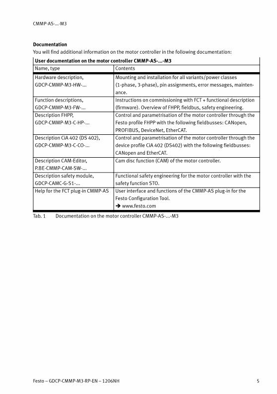
Documentation
You will find additional information on the motor controller in the following documentation:
User documentation on the motor controller CMMP-AS-...-M3
Name, type Contents
Hardware description,
GDCP-CMMP-M3-HW-...
Mounting and installation for all variants/power classes
(1-phase, 3-phase), pin assignments, error messages, mainten-
ance.
Function descriptions,
GDCP-CMMP-M3-FW-...
Instructions on commissioning with FCT + functional description
(firmware). Overview of FHPP, fieldbus, safety engineering.
Description FHPP,
GDCP-CMMP-M3-C-HP-...
Control and parametrisation of the motor controller through the
Festo profile FHPP with the following fieldbusses: CANopen,
PROFIBUS, DeviceNet, EtherCAT.
Description CiA 402 (DS 402),
GDCP-CMMP-M3-C-CO-...
Control and parametrisation of the motor controller through the
device profile CiA 402 (DS402) with the following fieldbusses:
CANopen and EtherCAT.
Description CAM-Editor,
P.BE-CMMP-CAM-SW-...
Cam disc function (CAM) of the motor controller.
Description safety module,
GDCP-CAMC-G-S1-...
Functional safety engineering for the motor controller with the
safety function STO.
Help for the FCT plug-in CMMP-AS User interface and functions of the CMMP-AS plug-in for the
Festo Configuration Tool.
�www.festo.com
Tab. 1 Documentation on the motor controller CMMP-AS-...-M3

1 Introduction
6 Festo – GDCP-CMMP-M3-RP-EN – 1206NH
1 Introduction
1.1 Important instructions
Warning
Danger of electric shock.
– Whenmodules or cover plates are not mounted on the slots Ext1 … Ext3.
– When cables are not mounted to the plugs [X6] and [X9].
– When connecting cables are disconnected when powered.
Touching live parts causes severe injuries and can lead to death.
The product may only be operated in a built-in status and when all protective measures
have been initiated.
Before touching live parts during maintenance, repair and cleaning work and when there
have been long service interruptions:
1. Switch off power to the electrical equipment via the mains switch and secure it
against being switched on again.
2. After switch-off, wait at least 5 minutes discharge time and check that power is
turned off before accessing the controller.
Observe the safety instructions (� hardware description, GDCP-CMMP-AS-M3-HW) dur-
ing mounting and installation work.
Note
Damage to the interface or motor controller due to incorrect handling.
• Switch off the supply voltage before mounting and installation work. Switch on sup-
ply voltage only whenmounting and installation work are completely finished.
• Never unplug modules from the motor controller or plug them in when powered!
• Observe the handling specifications for electrostatically sensitive devices. Do not
touch the printed circuit board and the pins of the manifold rail in the motor control-
ler. Grip the interface only on the front panel or on the edge of the board.
• Proceed carefully when mounting. When dismantling the CMMP-AS and mounting
the CMMP-AS-...-M3, make sure that no metal shavings, metal dust or mounting
parts (screws, nuts, pieces of wire, etc.) fall into the motor controller.

1 Introduction
Festo – GDCP-CMMP-M3-RP-EN – 1206NH 7
1.2 Overview
The Festo Configuration Tool (FCT) is the software platform for configuring and commissioning different
components from Festo. A plug-in with all of the necessary descriptions and dialogues is available for
the special requirements of these components. The system components are configured with the help of
these plug-ins. The entire configuration for all of the individual components is summarised and stored
in an FCT project.
The plug-ins for various components are available in several versions. In order to use the updated ver-
sion of the plug-ins the original FCT project needs to be converted.
Use of a CMMP-AS-...-M3 motor controller as a substitute for a CMMP-AS unit in your system requires
the installation and use of CMMP-AS plug-in version 2.0.x.
1.3 Prerequisites
A motor controller CMMP-AS-...-M3 entire system is shown in� Fig. 1.1� page 8.
To replace the motor controller with an older model, you will need the following:
– Motor controller CMMP-AS-...-M3 as a replacement device for CMMP-AS
– Card module for CMMP-AS-...-M3 in slot Ext3:
– Micro switch module CAMC-DS-M1 without STO function or
– Safety module CAMC-G-S1 with STO function,
– 24 VDC power supply for logic supply to the motor controller,
– PC with USB or Ethernet interface and corresponding connecting cable,
– Installed software plug-in CMMP-AS from version 2.0.x.
Depending on the initial situation you will also need� Tab. 1.1:
Initial situation you will also need Procedure overview
The previously used
CMMP-AS is opera-
tional and can be ac-
cessed.
– the existing CMMP-AS,
– an RS232 interface on the PC for the
CMMP-AS and a corresponding con-
necting cable.
1. Upload from the CMMP-AS to
the project with plug-in 2.0.x.
2. Convert controller in the FCT.
3. Mount and install new
CMMP-AS-...-M3.
4. Download the project to the
CMMP-AS-...-M3
The previously used
CMMP-AS is non-op-
erational.
– FCT project with the configured
component of the existing
CMMP-AS,
– Installed CMMP-AS plug-in (version
1.0.x … 1.4.x) which has been used
in the FCT project to date to config-
ure the CMMP-AS,
– Installed software “Festo FCT Pro-
ject Converter”.
1. Archive project in the FCT.
2. Convert project archive with
the FCT Project Converter.
3. De-archive project.
4. Mount and install new
CMMP-AS-...-M3.
5. Download the project to the
CMMP-AS-...-M3
Tab. 1.1 Initial situation with additionally required components
1 Introduction
8 Festo – GDCP-CMMP-M3-RP-EN – 1206NH
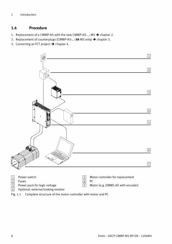
1.4 Procedure
1. Replacement of a CMMP-AS with the new CMMP-AS-...-M3� chapter 2.
2. Replacement of counterplugs (CMMP-AS-…-3A-M3 only)� chapter 3.
3. Converting an FCT project� chapter 4.
1
2
3
4
5
6
7
1 Power switch
2 Fuses
3 Power pack for logic voltage
4 Optional: external braking resistor
5 Motor controller for replacement
6 PC
7 Motor (e.g. EMMS-AS with encoder)
Fig. 1.1 Complete structure of the motor controller with motor and PC

1 Introduction
Festo – GDCP-CMMP-M3-RP-EN – 1206NH 9
1.5 Device view by comparison
1
2
3
4
5
6
7
8
9
aJ
aA
aB
aC
1 Slot for switch or safety module [Ext3] 1)
2 Fieldbus settings [S1] 1)
3 Slots for interfaces [Ext1/Ext2]
4 Activation of firmware download [S3] 1)
5 SD-/MMC card slot [M1] 1)
6 Activation of CANopen terminating
resistor [S2] 1)
7 CANopen interface [X4]
8 Ethernet interface [X18] 1)
9 USB interface [X19] 1)
aJ 7-segment display
aA Reset pushbutton
aB LEDs
aC PE connection
1) does not exist on CMMP-AS
Fig. 1.2 Motor controller CMMP-AS-...-M3: front view
1 Introduction
10 Festo – GDCP-CMMP-M3-RP-EN – 1206NH
4
5
3
2
1
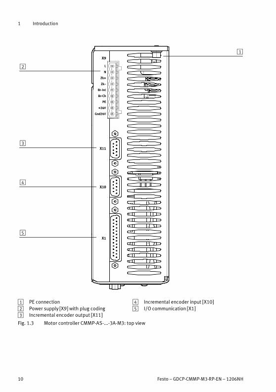
1 PE connection
2 Power supply [X9] with plug coding
3 Incremental encoder output [X11]
4 Incremental encoder input [X10]
5 I/O communication [X1]
Fig. 1.3 Motor controller CMMP-AS-...-3A-M3: top view

1 Introduction
Festo – GDCP-CMMP-M3-RP-EN – 1206NH 11
4
3
2
1
5
1 PE connection
2 Power supply [X9]
3 Incremental encoder output [X11]
4 Incremental encoder input [X10]
5 I/O communication [X1]
Fig. 1.4 Motor controller CMMP-AS-...-11A-P3-M3: top view
1 Introduction
12 Festo – GDCP-CMMP-M3-RP-EN – 1206NH
12
3
4
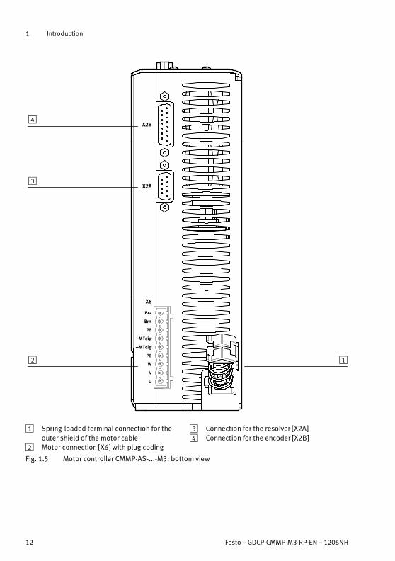
1 Spring-loaded terminal connection for the
outer shield of the motor cable
2 Motor connection [X6] with plug coding
3 Connection for the resolver [X2A]
4 Connection for the encoder [X2B]
Fig. 1.5 Motor controller CMMP-AS-...-M3: bottom view
2 Mechanical conversion
Festo – GDCP-CMMP-M3-RP-EN – 1206NH 13
2 Mechanical conversion
2.1 Dismantling
Note
Before dismantling the CMMP-AS:
• Make sure the corresponding FCT project with the configured CMMP-AS component
is present on your PC (� 4.2).
The CMMP-AS plug-in version 2.0.x can be used to load the configuration of a CMMP-AS
into an FCT project via the “upload” function and to convert the motor controller in the
project to CMMP-AS-...-M3. Conversion with the FCT Project Converter is then not neces-
sary.
2.1.1 Disconnecting cables
Almost all of the connections for connecting the CMMP-AS can be used unchanged on the
CMMP-AS-...-M3� chapter 3.
• Loosen the corresponding screws and disconnect all of the plug connectors on the
CMMP-AS.
• Loosen the PE connection on the CMMP-AS.
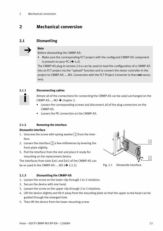
2.1.2 Removing the interface
Dismantle interface
1. Unscrew the screw with spring washer1 from the inter-
face.
2. Loosen the interface2 a few millimetres by levering the
front plate slightly.
3. Pull the interface from the slot and place it ready for
mounting on the replacement device.
The interfaces from slots Ext1 and Ext2 of the CMMP-AS can
be re-used in the CMMP-AS-...-M3 (� 2.2.1).
2
1
Fig. 2.1 Dismantle interface
2.1.3 Dismantling the CMMP-AS
1. Loosen the screw on the lower clip through 2 to 3 rotations.
2. Secure the device with one hand.
3. Loosen the screw on the upper clip through 2 to 3 rotations.
4. Lift the device slightly and tilt it away from the mounting plate so that the upper screw head can be
guided through the enlarged hole.
5. Then lift the device from the lower mounting screw.
2 Mechanical conversion
14 Festo – GDCP-CMMP-M3-RP-EN – 1206NH
2.2 Mounting
2.2.1 Allocation of slot Ext1 and Ext2
Note
Operation of the Profibus interface CAMC-PB in the motor controller CMMP-AS-...-M3 is
only permissible in slot Ext2.
• Make sure that slot Ext1 is only used for other interfaces.
• Observe the instructions and mount the dismantled interfaces of the CMMP-AS in slots Ext1 and
Ext2 of the CMMP-AS-...-M3 (�description GDCP-CMMP-M3-HW-…).
2.2.2 Allocation of slot Ext3
• Mount a suitable extension module in slot Ext3 of the CMMP-AS-...-M3
(� description GDCP-CMMP-M3-HW-…).
Type Description
CAMC-G-S1 Safety module with STO function and DIP switches.
CAMC-DS-M1 Switch module with DIP switches, no safety functions.
Tab. 2.1 Overview of extension modules for the CMMP-AS-...-M3
2.2.3 Mounting the CMMP-AS-...-M3
Note
Excessive heating can lead to premature aging and/or damage to the device.
• Make sure the recommended minimum distances are maintained in the event of high
thermal stress of the CMMP-AS-...-M3 (� description GDCP-CMMP-M3-HW-…).
The clips used for CMMP-AS and CMMP-AS-...-M3 are identical. This means the existing
mounting screws can be reused.
1. Position the lower clip of the slightly tilted device on the lower mounting screw.
2. Place the device on the mounting plate and guide the upper screw head through the large hole of
the upper clip.
3. Slide the device down slightly until it is positioned securely in the elongated holes of the clips. Con-
tinue to secure the device with one hand.
4. Tighten the two mounting screws.

2 Mechanical conversion
Festo – GDCP-CMMP-M3-RP-EN – 1206NH 15
2.3 DIP switch setting [S1]
The CMMP-AS-...-M3 is equipped with a DIP switch [S1] on the extension module in slot Ext3.
The status of the DIP switches is read when the control voltage is switched on or upon RESET. The mo-
tor controller takes over changes to the switch setting in ongoing operation only at the next switch-on
or RESET.
The significance of the DIP switch setting depends on the control interface used.
Activate fieldbus
DIP switch 8 Fieldbus interface
1 Enabled
0 Disabled
Tab. 2.2 Activation of the fieldbus
With DIP switch 8, the fieldbus of the plugged-in interface CAMC-... is activated. If no
interface is plugged in, the CAN bus [X4] is activated.
Setting the bit rate
When using CANopen, DriveBus and DeviceNet the bit rate is set via the DIP switch. Configuration via
FCT is no longer possible.
DIP switch 1 Mbit/s1) 500 kbps 250 kBit/s 125 kBit/s
6 ON OFF ON OFF
7 ON ON OFF OFF
1) Only for CANopen/DriveBus; for DeviceNet, is limited to 500 kBit/s
Tab. 2.3 Bit rate setting for CANopen, DriveBus and DeviceNet
Setting the node number
The node number for CANopen, DriveBus, DeviceNet and PROFIBUS can be set for the CMMP-AS-...-M3
via the sum of the base address (FCT) and offset (DIP switch).
Recommendation: When exchanging, set the following dip switches to 0 so that the ad-
dress specified in the FCT corresponds to the node number (compatible with CMMP-AS):
– CANopen, DriveBus, DeviceNet: DIP switch 1 … 5 = 0
– PROFIBUS: DIP switch 1 … 7 = 0

3 Electrical conversion
16 Festo – GDCP-CMMP-M3-RP-EN – 1206NH
3 Electrical conversion
For electrical connection of the CMMP-AS-...-M3:
1. Connect the central PE connection of your system to the PE connection on the backwall of the
CMMP-AS-...-M3.
2. Use the screening clamp to connect the screening of the motor connection to the housing of the
CMMP-AS-...-M3.
3. Connect the other plug connectors as described below.
Almost all of the connections for connecting the CMMP-AS can be used unchanged on the
CMMP-AS-...-M3.
• Please observe the following exceptions for the CMMP-AS-…-3A-M3.
– Plug connector for connecting the motor [X6]
– Plug connector for connecting the power supply [X9]
These plug connectors on the CMMP-AS-…-3A-M3 exhibit a different shape. A replacement of the re-
spective counterplugs is therefore required (� chapter 3.1 and 3.2).
The shape of the 9-pin plug connectors for connections [X6] and [X9] is identical on the
CMMP-AS-…-3A-M3. Any confusion regarding these plugs and the corresponding counter-
plugs is prevented through the use of coding.
All other counterplugs can be reused.
Connection Plug connector on the device Counterplug
I/O communication [X1] D-SUB-25-pin, socket D-SUB-25-pin, pins
Resolver [X2A] D-SUB- 9-pin, socket D-SUB- 9-pin, pins 1)
Encoder [X2B] D-SUB-15-pin, socket D-SUB-15-pin, pins
CAN bus [X4] D-SUB- 9-pin, pin D-SUB- 9-pin, socket
Motor [X6]
(CMMP-AS-…-11A-P3-M3 only)
PHOENIX Power-COMBICON
PC 4/9-G-7,62-BK
PHOENIX Power-COMBICON
PC 4HV/9-ST-7,62-BK
Power supply [X9]
(CMMP-AS-…-11A-P3-M3 only)
PHOENIX Power-COMBICON PC
4/11-G-7,62-BK
PHOENIX Power-COMBICON PC
4 HV/11-ST-7,62-BK
Incremental encoder input [X10] D-SUB- 9-pin, socket D-SUB- 9-pin, pins 1)
Incremental encoder output [X11] D-SUB- 9-pin, socket D-SUB- 9-pin, pins 1)
1) Caution! Risk of confusion
Tab. 3.1 Existing counterplugs for use on the CMMP-AS-...-M3
Note
Plug connectors [X2A], [X10] and [X11] on the CMMP-AS-...-M3 are identical.
• Before switching on the device check to make sure the appropriate counterplugs are
connected correctly (see code�Tab. 3.1).
Control cable and D-Sub plug�www.festo.com/catalogue.

3 Electrical conversion
Festo – GDCP-CMMP-M3-RP-EN – 1206NH 17
3.1 Exchanging the counterplug [X6]
Counterplug [X6] only needs to be exchanged for the CMMP-AS-…-3A-M3.
Plug connector [X6] of the CMMP-AS-...-M3 is coded at pin 1. The corresponding counterplug exhibits a
blockade at pin 9.
Motor controller Design on the device Cod. Counterplug Block.
CMMP-AS-C2-3A-M3 PHOENIX Contact
MSTBA 2,5/9-G-5,08-BK
PIN1 (BR-) PHOENIX Contact
MSTB 2,5/9-ST-5,08-BK
PIN9 (U)
CMMP-AS-C5-3A-M3
Tab. 3.2 Plug design [X6]
• Use the counterplug at connection [X6] of the CMMP-AS-...-M3 (delivery status).
• Loosen the screws on the old counterplug and attach the free cables to the corresponding pin con-
nections of the new counterplug.
The assignment of the counterplug on the CMMP-AS and the CMMP-AS-...-M3 for connecting the motor
is pin-compatible.
Pin assignment [X6] Pin no. Counterplug CMMP-AS Counterplug CMMP-AS-...-M3
BR- 1
BR+ 2
Protective earth 3
-MTdig 4
+MTdig 5
Protective earth 6
W 7
V 8
U 9
1) Example plug from the motor controller CMMP-AS-...-3A-M3
Tab. 3.3 Pin assignment [X6] - motor connection
3 Electrical conversion
18 Festo – GDCP-CMMP-M3-RP-EN – 1206NH
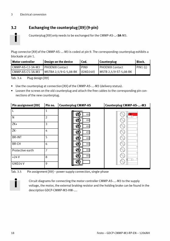
3.2 Exchanging the counterplug [X9] (9-pin)
Counterplug [X9] only needs to be exchanged for the CMMP-AS-…-3A-M3.
Plug connector [X9] of the CMMP-AS-...-M3 is coded at pin 9. The corresponding counterplug exhibits a
blockade at pin 1.
Motor controller Design on the device Cod. Counterplug Block.
CMMP-AS-C2-3A-M3 PHOENIX Contact
MSTBA 2,5/9-G-5,08-BK
PIN9
(GND24V)
PHOENIX Contact
MSTB 2,5/9-ST-5,08-BK
PIN1 (L)
CMMP-AS-C5-3A-M3
Tab. 3.4 Plug design [X9]
• Use the counterplug at connection [X9] of the CMMP-AS-...-M3 (delivery status).
• Loosen the screws on the old counterplug and attach the free cables to the corresponding pin con-
nections of the new counterplug.
Pin assignment [X9] Pin no. Counterplug CMMP-AS Counterplug CMMP-AS-...-M3
L 1
N 2
ZK+ 3
ZK- 4
BR-INT 5
BR-CH 6
Protective earth 7
+24 V 8
GND24 V 9
Tab. 3.5 Pin assignment [X9] – power supply connection, single-phase
Circuit diagrams for connecting the motor controller CMMP-AS-...-M3 to the supply
voltage, the motor, the external braking resistor and the holding brake can be found in the
description GDCP-CMMP-M3-HW-....
3 Electrical conversion
Festo – GDCP-CMMP-M3-RP-EN – 1206NH 19
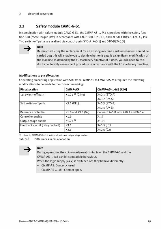
3.3 Safety module CAMC-G-S1
In combination with safety module CAMC-G-S1, the CMMP-AS-...-M3 is provided with the safety func-
tion STO (“Safe Torque Off”) in accordance with EN 61800-5-2 SIL3, and EN ISO 13849-1, Cat. 4 / PLe.
Two switch-off paths are realised via control ports STO-A [X40.1] and STO-B [X40.3].
Note
Before conducting the replacement for an existing machine a risk assessment should be
carried out; this will enable you to decide whether it entails a significant modification of
the machine as defined by the EC machinery directive. If it does, you will need to con-
duct a conformity assessment procedure in accordance with the EC machinery directive.
Modifications to pin allocation
Converting an existing application with STO from CMMP-AS to CMMP-AS-M3 requires the following
modifications to be made to the connection wiring:
Pin allocation CMMP-AS CMMP-AS-...-M3 [X40]
1st switch-off path X1.21 1) (DIN4) X40.1 (STO-A)
X40.2 (0V-A)
2nd switch-off path X3.2 (REL) X40.3 (STO-B)
X40.4 (0V-B)
Reference potential X1.6 and X3.3 (0V) Connect X40.8 with X40.2 and X40.4
Controller enable X1.9 X1.9
Output stage enable X1.21 1) X1.21
Feedback circuit (relay contact) X3.5 X40.5 (C1)
X3.6 X40.6 (C2)
1) Used by CMMP-AS for 1st switch-off path and output stage enable.
Tab. 3.6 Differences in pin allocation
Note
During operation, the acknowledgment contacts on the CMMP-AS and the
CMMP-AS-...-M3 exhibit compatible behaviour.
When the logic supply (24 V) is switched off, they behave differently:
– CMMP-AS: Contact closed.
– CMMP-AS-...-M3: Contact open.

4 Converting a project
20 Festo – GDCP-CMMP-M3-RP-EN – 1206NH
4 Converting a project
FCT projects are converted with the Festo FCT Project Converter. This programme adapts the data
format for configuring individual components to the selected plug-in version. The converted FCT project
can be re-opened and edited in the FCT with appropriately installed plug-ins. This means that after an
FCT project has been converted, the CMMP-AS motor controller can be configured without restriction
by using the new plug-in version 2.0.
After replacing the motor controller you will need to convert the CMMP-AS component to a CMMP-
AS-...-M3 in the configuration. The conversion command can be found within the FCT plug-in CMMP-AS
version 2.0.x� 4.5.
4.1 Overview
Converting an FCT project with a configured CMMP-AS for use with a CMMP-AS-...-M3 requires several
steps, which are to be executed as follows.
Step Activity � (see)
1 Archive existing project with FCT Chapter 4.2
2 Select archive file with FCT Project Converter Chapter 4.3
3 Set options for conversion
4 Execute conversion
5 Save converted project to archive file
6 Extract archive file with FCT Chapter 4.4
7 Change motor controller Chapter 4.5
8 Adapt configuration Chapter 4.6
Tab. 4.1 Conversion overview
The CMMP-AS plug-in version 2.0.x can be used to load the configuration of a CMMP-AS
directly into an FCT project via the “upload” function. This project does not need to be
converted for use of a CMMP-AS-...-M3.
• In this case start the above-mentioned activities from step 7.
Recommendation: Review of the fieldbus settings
Check the fieldbus settings where necessary, as these settings in the CMMP-AS-...-M3 are partly de-
pendent on the DIP switch setting,� also refer to chapter 2.3.

4 Converting a project
Festo – GDCP-CMMP-M3-RP-EN – 1206NH 21
4.2 Preparing a project
Archiving a project with FCT
Data that has been archived with the FCT is used exclusively to convert a project with the
FCT Project Converter.
Archives that have been created with other programmes are not supported.
1. Start the programme Festo Configuration Tool (FCT).
2. Open the FCT project that is to be converted for use with the motor controller CMMP-AS-...-M3
(�online help).
3. Select the menu command [Project] [Archive].
A dialogue window opens in the FCT for archiving the project.
Fig. 4.1 Archiving an FCT project
The default setting is to save the project in the FCT archive folder. This archive folder is also used by the
FCT Project Converter by default (“Archive” folder in the installation index of the FCT).
4. Select options for archiving the project where necessary (� online help).
5. Start the archiving process by pressing “OK”.

4 Converting a project
22 Festo – GDCP-CMMP-M3-RP-EN – 1206NH
Fig. 4.2 Archiving a project - progress display
All of the configuration settings for the project are now saved in a special FCT archive file (*.zip).
4 Converting a project
Festo – GDCP-CMMP-M3-RP-EN – 1206NH 23
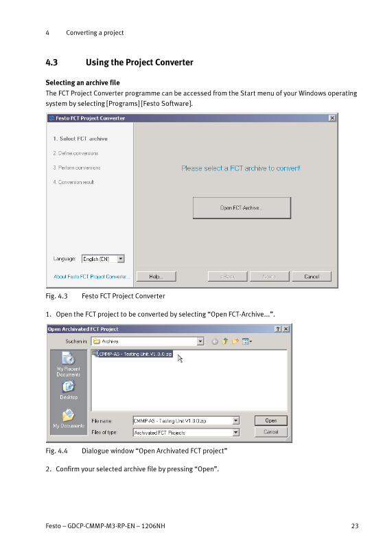
4.3 Using the Project Converter
Selecting an archive file
The FCT Project Converter programme can be accessed from the Start menu of your Windows operating
system by selecting [Programs] [Festo Software].
Fig. 4.3 Festo FCT Project Converter
1. Open the FCT project to be converted by selecting “Open FCT-Archive...”.
Fig. 4.4 Dialogue window “Open Archivated FCT project”
2. Confirm your selected archive file by pressing “Open”.

4 Converting a project
24 Festo – GDCP-CMMP-M3-RP-EN – 1206NH
The archive file is loaded into the FCT Project Converter.
All of the components of the FCT project are presented in the programme.
1 2
345
1 Title of the loaded FCT project
2 Overview of all components in the FCT pro-
ject, with details of the plug-in version used
when creating the component
3 Working directory and selected archive file
with FCT project
4 Language setting
5 Information about the programme version
and available conversion options
Fig. 4.5 FCT Project Converter with selected FCT project
3. Open an alternative archive file, if necessary, by selecting “Change...”.
4. Confirm your selected archive file by pressing “Next >”.
4 Converting a project
Festo – GDCP-CMMP-M3-RP-EN – 1206NH 25
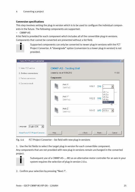
Conversion specifications
This step involves setting the plug-in version which is to be used to configure the individual compon-
ents in the future. The following components are supported:
– CMMP-AS
A list field is provided for each component which includes all of the convertible plug-in versions.
Components that cannot be converted are presented without a list field.
Supported components can only be converted to newer plug-in versions with the FCT
Project Converter. A “downgrade” option (conversion to a lower plug-in version) is not
provided.
Fig. 4.6 FCT Project Converter – list field with new plug-in versions
1. Use the list fields to select the target plug-in version for each convertible component.
Any components that are not provided with new plug-in versions remain unchanged in the converted
project.
Subsequent use of a CMMP-AS-...-M3 as an alternative motor controller for an axis in your
system requires the selection of plug-in version 2.0.x.
2. Confirm your selection by pressing “Next >”.

4 Converting a project
26 Festo – GDCP-CMMP-M3-RP-EN – 1206NH
Executing the conversion process
The FCT project is converted automatically without any further queries.
Fig. 4.7 Image: Conversion process being executed
Result of the conversion process
The result of the conversion process is subsequently displayed.
Fig. 4.8 FCT Project Converter – Result of the conversion process
If an error occurs, the affected components are designated with an error symbol. These errors can be
displayed by clicking “Show error details ...”. Faulty components are saved without change in the data
format used for the original plug-in version.

4 Converting a project
Festo – GDCP-CMMP-M3-RP-EN – 1206NH 27
The FCT project has been converted, however, the archive file has not yet been saved. The FCT Project
Converter generates an identical file name with a new version number based on the loaded archive file.
• Click the “Finish” button:
– to save the archive file with the selected settings,
– then to exit the programme without any further queries.
Further commands
Button Function
Browse... Opens a dialogue window
– to select a new name for the archive file to be saved,
– to select an alternative directory.
< Back Skip backwards
– to select the target plug-in versions for the conversion process
(� see previous section “Conversion specifications”).
Cancel Exits the programme without saving the archive file.
Finish Saves the archive file with the selected settings. The programme is then exited
without any further queries.
Tab. 4.2 FCT Project Converter – button functions
4 Converting a project
28 Festo – GDCP-CMMP-M3-RP-EN – 1206NH
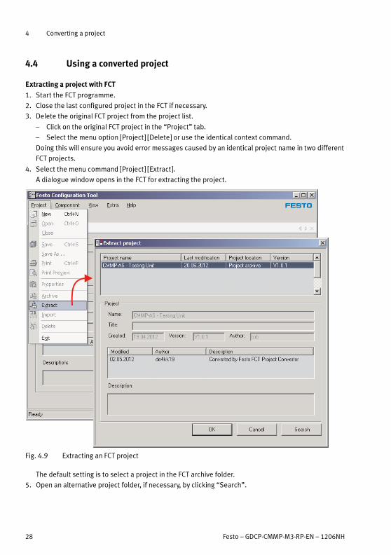
4.4 Using a converted project
Extracting a project with FCT
1. Start the FCT programme.
2. Close the last configured project in the FCT if necessary.
3. Delete the original FCT project from the project list.
– Click on the original FCT project in the “Project” tab.
– Select the menu option [Project] [Delete] or use the identical context command.
Doing this will ensure you avoid error messages caused by an identical project name in two different
FCT projects.
4. Select the menu command [Project] [Extract].
A dialogue window opens in the FCT for extracting the project.
Fig. 4.9 Extracting an FCT project
The default setting is to select a project in the FCT archive folder.
5. Open an alternative project folder, if necessary, by clicking “Search”.
4 Converting a project
Festo – GDCP-CMMP-M3-RP-EN – 1206NH 29
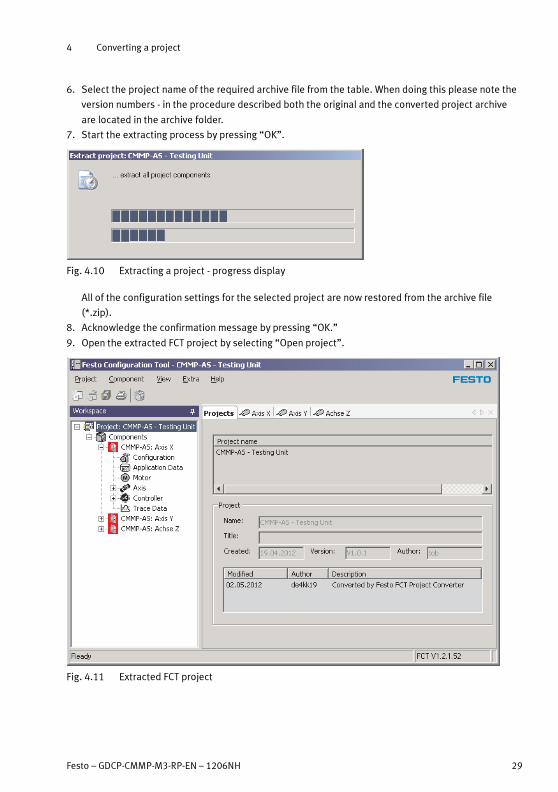
6. Select the project name of the required archive file from the table. When doing this please note the
version numbers - in the procedure described both the original and the converted project archive
are located in the archive folder.
7. Start the extracting process by pressing “OK”.
Fig. 4.10 Extracting a project - progress display
All of the configuration settings for the selected project are now restored from the archive file
(*.zip).
8. Acknowledge the confirmation message by pressing “OK.”
9. Open the extracted FCT project by selecting “Open project”.
Fig. 4.11 Extracted FCT project
4 Converting a project
30 Festo – GDCP-CMMP-M3-RP-EN – 1206NH
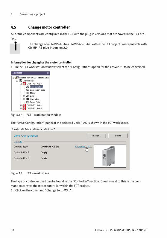
4.5 Change motor controller
All of the components are configured in the FCT with the plug-in versions that are saved in the FCT pro-
ject.
The change of a CMMP--AS to a CMMP-AS-...-M3 within the FCTproject is only possiblewithCMMP--AS plug-in version 2.0.
Information for changing the motor controller
1. In the FCT workstation window select the “Configuration” option for the CMMP-AS to be converted.
Fig. 4.12 FCT – workstation window
The “Drive Configuration” panel of the selected CMMP-AS is shown in the FCT work space.
Fig. 4.13 FCT – work space
The type of controller used can be found in the “Controller” section. Directly next to this is the com-
mand to convert the motor controller within the FCT project.
2. Click on the command “Change to …-M3…”.

4 Converting a project
Festo – GDCP-CMMP-M3-RP-EN – 1206NH 31
Using the compatibility mode
When changing a CMMP-AS to a CMMP-AS-...-M3, the device ID of the exchanged motor controller can
continue to be used. The following dialogue window opens here.
Fig. 4.14 FCT – compatible device substitution
3. Decide on the use of the compatibility mode:
Default Button Comment
Fieldbus is not used. Disable Compatibility
Mode Fieldbus
Adaptation of the PLC pro-
gramme is not necessary.
CMMP-AS-...-M3 reports via fieldbus with
its own device ID.
Disable Compatibility
Mode Fieldbus
Adaptation of the PLC pro-
gramme is necessary.
CMMP-AS-...-M3 reports via fieldbus with
the device ID of the replaced motor con-
troller.
Enable Compatibility
Mode Fieldbus
Adaptation of the PLC pro-
gramme is not necessary.
Tab. 4.3 Selection aid
Using a new CMMP-AS-...-M3
After a successful change the drive configuration is shown in the FCT work space with the new motor
controller CMMP-AS-...-M3.
Fig. 4.15 FCT – work space

4 Converting a project
32 Festo – GDCP-CMMP-M3-RP-EN – 1206NH
4.6 Adapt configuration
To conclude the commissioning process for the CMMP-AS-...-M3 as a replacement for the CMMP-AS,
the following adaptations are to be executed in the FCT.
1. Select the interface for communication between FCT and CMMP-AS-...-M3.
2. Select an extension module for slot Ext3.
3. Check the fieldbus settings.
4.6.1 Selecting the FCT interface
The serial interface is no longer available for communication with the CMMP-AS-...-M3. This requires
the selection of a new FCT interface for the CMMP-AS-...-M3.
1
2
1 [X19]: USB 2 [X18]: Ethernet
Fig. 4.16 FCT communication interface of the CMMP-AS-...-M3
1. Select the component CMMP-AS-...-M3 in the FCT “Workspace” window.
2. Select the menu command [Component] [FCT Interface].
Fig. 4.17 FCT interface dialogue window
3. Use the “Ethernet” or “USB” tab, for example, for communication with the CMMP-AS-...-M3 (Ether-
net is selected in this example).
4 Converting a project
Festo – GDCP-CMMP-M3-RP-EN – 1206NH 33
To configure the Ethernet connection:
• Enter the IP address and port manually
or
1. Start the programme and search for devices within your network by clicking “Scan...” (� Festo
Device Tool).
2. Identify the CMMP-AS-...-M3 (� Festo Device Tool).
3. Confirm your selection by pressing “OK”.
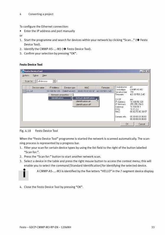
Festo Device Tool
Fig. 4.18 Festo Device Tool
When the “Festo Device Tool” programme is started the network is scanned automatically. The scan-
ning process is represented by a progress bar.
1. Filter your scan for certain device types by using the list field to the right of the button labelled
“Scan for:”.
2. Press the “Scan for:” button to start another network scan.
3. Select a device in the table and press the right mouse button to access the context menu; this will
enable you to select the command [Standard Identification] for identifying the selected device.
A CMMP-AS-...-M3 is identified by the five letters “HELLO” in the 7-segment device display.
4. Close the Festo Device Tool by pressing “OK”.

4 Converting a project
34 Festo – GDCP-CMMP-M3-RP-EN – 1206NH
4.6.2 Interfaces for Ext1 and Ext2
The original interface assignment is transferred from the old project or the old CMMP-AS.
Configuration only needs to be checked in exceptional cases, for example, if the PROFIBUS interface
has been installed in slot 1.
4.6.3 Selecting the extension module for Ext3
After the conversion process the configuration includes the micro switch module CAMC-DS-M1.
The use of a safety module in slot Ext3 (mounting� chapter 2.2.2) requires a corresponding configura-
tion of the CMMP-AS-...-M3 in the FCT project.
1. Open the “Drive Configuration” work space for the converted
CMMP-AS-...-M3 in the FCT (�Fig. 4.12).
2. Press the “Change…” button to open the “Edit Drive Configuration” dialogue window.
3. Select the STO module CAMC-G-S1 from the list field for slot Ext3.
Fig. 4.19 Selecting the extension module for Ext3
4. Click the “Next >” and “Finish” buttons.

4 Converting a project
Festo – GDCP-CMMP-M3-RP-EN – 1206NH 35
If the extension module is replaced, it has an impact on the validity of data for various configuration
parameters.
Fig. 4.20 Change component/property dialogue window
Note
Leave the preset “Reset affected pages to their default values”. Otherwise all of the
settings of the previous CMMP-AS would be reset!
5. Confirm the message in the dialogue window by pressing “OK”.
Establishing an online connection
1. Establish an online connection to the CMMP-AS-...-M3 in the FCT.
The exchanged CMMP-AS-...-M3 is not yet configured. A dialogue window is therefore displayed with a
request to synchronise the project and device data.
Fig. 4.21 Synchronise project and device data dialogue window
2. Click the “Download” button to transfer the configuration to the CMMP-AS-...-M3.
4 Converting a project
36 Festo – GDCP-CMMP-M3-RP-EN – 1206NH
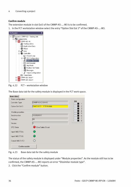
Confirmmodule
The extension module in slot Ext3 of the CMMP-AS-...-M3 is to be confirmed.
1. In the FCT workstation window select the entry “Option Slot Ext 3” of the CMMP-AS-...-M3.
Fig. 4.22 FCT – workstation window
The Base data tab for the safety module is displayed in the FCT work space.
Fig. 4.23 Base data tab for the safety module
The status of the safety module is displayed under “Module properties”. As the module still has to be
confirmed, the CMMP-AS-...-M3 reports an error “Dissimilar module type”.
2. Click the “Confirm module” button.
4 Converting a project
Festo – GDCP-CMMP-M3-RP-EN – 1206NH 37
The CMMP-AS-...-M3 must be restarted for this purpose.
Fig. 4.24 Message “Confirm module change”
3. Confirm the message by pressing “OK”.
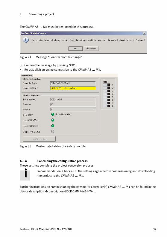
4. Re-establish an online connection to the CMMP-AS-...-M3.
Fig. 4.25 Master data tab for the safety module
4.6.4 Concluding the configuration process
These settings complete the project conversion process.
Recommendation: Check all of the settings again before commissioning and downloading
the project to the CMMP-AS-...-M3.
Further instructions on commissioning the new motor controller(s) CMMP-AS-...-M3 can be found in the
device description� description GDCP-CMMP-M3-HW-….

CMMP-AS-...-M3
38 Festo – GDCP-CMMP-M3-RP-EN – 1206NH
Index
A
Adapt configuration 32. . . . . . . . . . . . . . . . . . . . .
Archiving 21. . . . . . . . . . . . . . . . . . . . . . . . . . . . . .
C
CAMC-G-S1 19. . . . . . . . . . . . . . . . . . . . . . . . . . . .
Change motor controller 30. . . . . . . . . . . . . . . . .
Compatibility mode 31. . . . . . . . . . . . . . . . . . . . .
Counterplug replacement 17, 18. . . . . . . . . . . . .
D
Device view 9. . . . . . . . . . . . . . . . . . . . . . . . . . . .
DIP switch 15. . . . . . . . . . . . . . . . . . . . . . . . . . . .
Dismantling 13. . . . . . . . . . . . . . . . . . . . . . . . . . .
E
Electrical conversion 16. . . . . . . . . . . . . . . . . . . .
Ext slot allocation 14. . . . . . . . . . . . . . . . . . . . . . .
Extracting 28. . . . . . . . . . . . . . . . . . . . . . . . . . . . .
F
FCT Interface 32. . . . . . . . . . . . . . . . . . . . . . . . . .
I
Instructions on the description 4. . . . . . . . . . . . .
M
Mechanical conversion 13. . . . . . . . . . . . . . . . . .
Mounting 14. . . . . . . . . . . . . . . . . . . . . . . . . . . . .
P
Pin allocation modification 19. . . . . . . . . . . . . . .
Preparing a project 21. . . . . . . . . . . . . . . . . . . . . .
R
Removing the interface 13. . . . . . . . . . . . . . . . . .
S
Safety module 19. . . . . . . . . . . . . . . . . . . . . . . . .
Service 4. . . . . . . . . . . . . . . . . . . . . . . . . . . . . . . .
T
Target group 4. . . . . . . . . . . . . . . . . . . . . . . . . . . .
U
Using a project 28. . . . . . . . . . . . . . . . . . . . . . . . .
Using the Project Converter 23. . . . . . . . . . . . . . .


Reproduction, distribution or sale of this document or communica-tion of its contents to others without express authorization isprohibited. Offenders will be liable for damages. All rights re-served in the event that a patent, utility model or design patent isregistered.
Copyright:Festo AG & Co. KGPostfachD-73726 Esslingen
Phone:+49 711 347 0
Fax:+49 711 347 2144
e-mail:[email protected]
Internet:www.festo.com
Original: deVersion: 1206NH