motor current testing - frickcontrols.com lx... · quantum lx motor current testing the quantum lx...
TRANSCRIPT
Quantum LX
Motor Current Testing
Quantum LX
Motor Current Testing
� The Quantum LX control panel is capable of reading external analog devices, such as
Current transformers (CT) or other external devices, such as a VFD. It uses these input
signals for the purpose of monitoring and control of the motor current.
� The Quantum LX will accept one or the other of these two different input signals on two
separate analog board input connectors.
� Refer to the Quantum LX Analog board wiring diagram for detailed wiring and
Motor Current Test2
� Refer to the Quantum LX Analog board wiring diagram for detailed wiring and
connections.
� Review the following instructions in their entirety before beginning the testing. Example
Quantum LX screens and pictorials are provided for your reference.
Quantum LX
Motor Current Testing
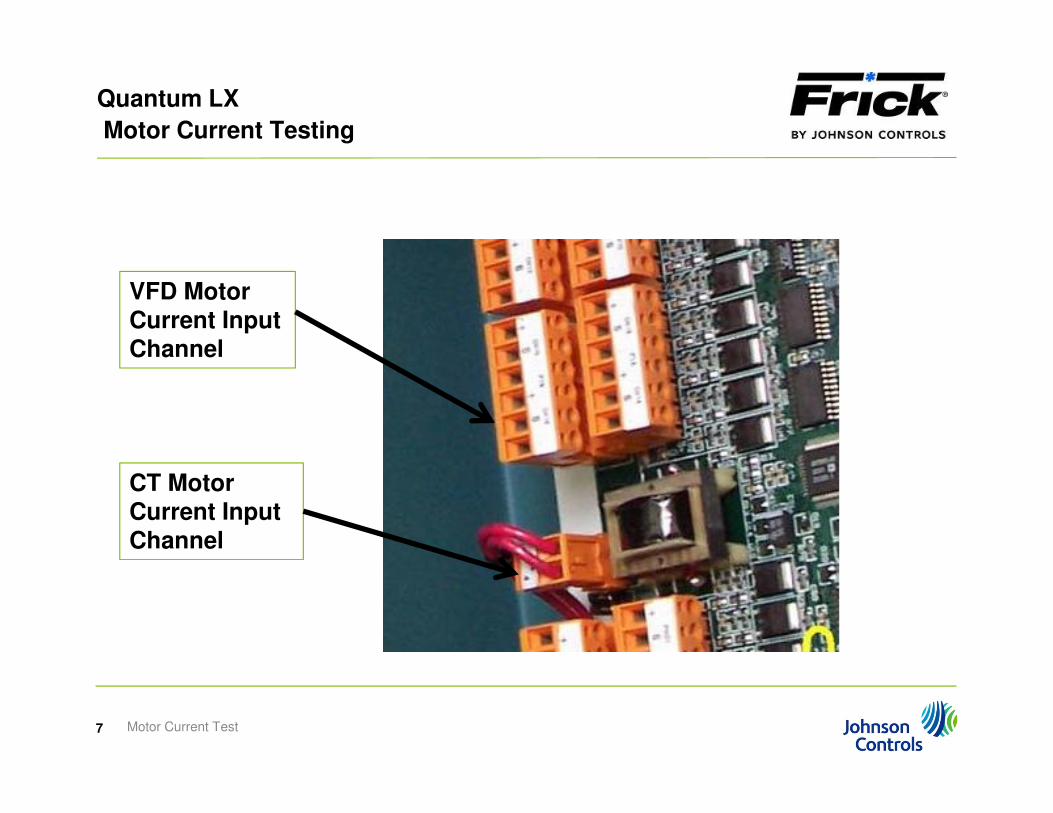
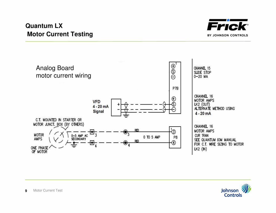
Motor Current from a CT or other external device
� The input signal from the CT enters the analog board on channel 16, directly from the
CT.
When working with the CT, do not have the CT wires disconnected while the motor is
running. High voltage will be present when the CT has no load.
� Always ensure that one side of the motor CT is grounded in the motor starter panel. The
Motor Current Test3
� Always ensure that one side of the motor CT is grounded in the motor starter panel. The
wire to the control panel terminal #2 is the only one grounded.
� The input from an external source, such as a 4-20 mA input from a VFD, enters the
analog board on channel 16, directly from the VFD.
Quantum LX
Motor Current Testing
Analog Boards
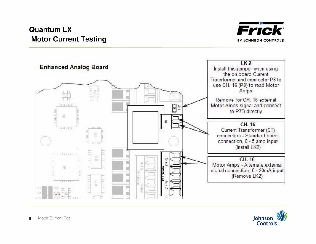
� Channel 16 of the Analog Board #1 is dedicated to reading motor amps, either directly
from a CT, or from an external DC mA or voltage device, such as from a VFD.
� When reading motor amps directly from a CT, the connection is at the P8 connector.
NOTE: The input signal cannot exceed 5 amps or the analog board will be damaged.
� If you are using an external DC mA or voltage device, such as from a VFD, the
Motor Current Test4
� If you are using an external DC mA or voltage device, such as from a VFD, the
connection is at the connector P7B.
� The 0-5 amp input signal from the CT or the 4-20 mA input signal from the VFD can be
viewed on the Quantum LX Service screen as a 0-5 vdc reading.

Quantum LX
Motor Current Testing
VFD Motor
Current Input Channel
Motor Current Test5
CT Motor
Current Input Channel

Quantum LX
Motor Current Testing
VFD Motor
Current Input Channel
Motor Current Test6
CT Motor
Current Input Channel
Quantum LX
Motor Current Testing
VFD Motor
Current Input Channel
Motor Current Test7
CT Motor
Current Input Channel
Quantum LX
Motor Current Testing
Motor Current Test8
Quantum LX
Motor Current Testing
Analog Board
motor current wiring
Motor Current Test9

Quantum LX
Motor Current Testing
Motor Current from a CT
� The motor CT is rated by its CT Factor. This is the ratio of the current transformer. The
CT Factor of the motor CT must match the CT Factor programmed in the Quantum LX
motor setpoint configuration.
� An example of a CT Factor is 300:5 (or a 300:5 ratio). This means with a 300 amp input
(primary) to the CT, it will output (secondary) a 5 amp signal.
� A proper CT Factor is determined by the calculation of the FLA (full load amps) and the
Motor Current Test10
� A proper CT Factor is determined by the calculation of the FLA (full load amps) and the
SF (service factor) of the motor.
� For example: FLA x SF x 1.1 = Recommended CT Factor (ratio).
� FLA (182) x SF (1.15) x 1.1 = 230.23 or 300 (round up to the nearest 100th).
� So you would use a CT with a ratio of 300:5.
� Typically the CT will have the ratio printed on the side of the CT.
Quantum LX
Motor Current Testing
Motor Setpoint
Data
Motor Current Test11
Quantum LX
Motor Current Testing
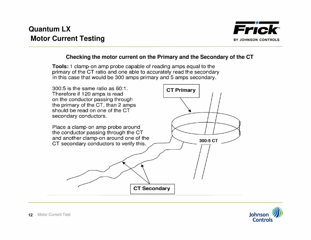
Checking the motor current on the Primary and the Secondary of the CT
Motor Current Test12
Quantum LX
Motor Current Testing
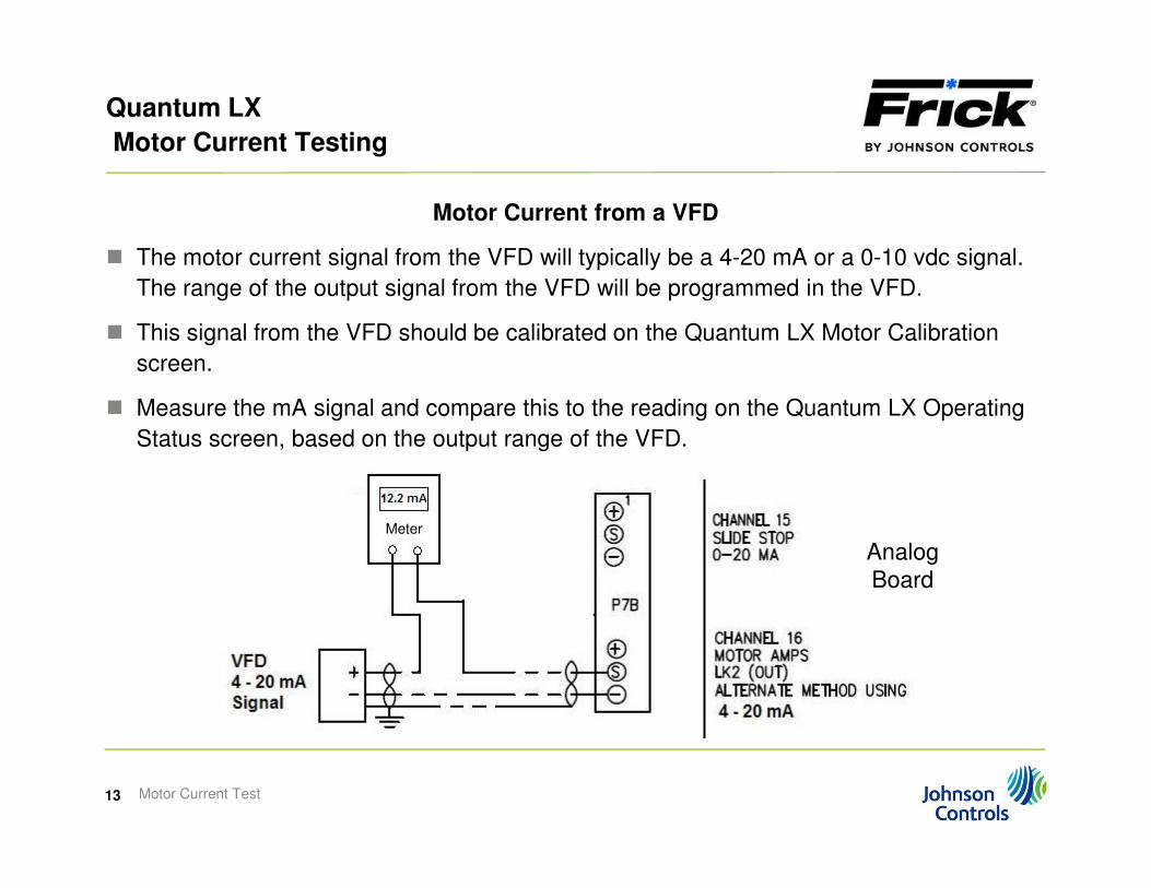
Motor Current from a VFD
� The motor current signal from the VFD will typically be a 4-20 mA or a 0-10 vdc signal.
The range of the output signal from the VFD will be programmed in the VFD.
� This signal from the VFD should be calibrated on the Quantum LX Motor Calibration
screen.
� Measure the mA signal and compare this to the reading on the Quantum LX Operating
Status screen, based on the output range of the VFD.
Motor Current Test13
Status screen, based on the output range of the VFD.
Analog
Board
Meter
Quantum LX
Motor Current Testing
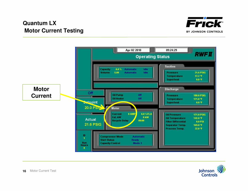
Motor Current on the Quantum LX
� The reading on the Quantum LX Service screen for analog board #1, channel 16, should
match in volts, the amp reading of the clamp-on meter around the CT secondary
conductor or the mA input from the VFD (20 mA = 5 vdc).
� The reading displayed on the Quantum LX Operating Status screen should match the
reading on the clamp-on meter around the conductor passing through the primary of the
CT or in the case of the VFD, the current output programmed in the VFD for the 4-20
mA signal based on the motor setpoint for the FLA in the Quantum LX.
Motor Current Test14
mA signal based on the motor setpoint for the FLA in the Quantum LX.
� If this is off by not more that 15% of the motor FLA, go to the calibration screen for the
motor current and correct (calibrate) the reading.

Quantum LX
Motor Current Testing
Motor
Current
Service
Screen
User Level 2
Motor Current Test15
Current (in volts)
User Level 2
Quantum LX
Motor Current Testing
Motor
Current
Motor Current Test16
Current
Quantum LX
Motor Current Testing
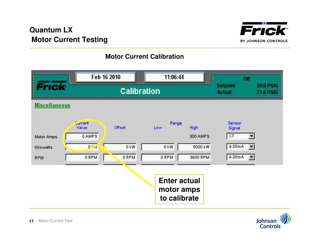
Motor Current Calibration
Motor Current Test17
Enter actual
motor amps to calibrate

Quantum LX
Motor Current Testing
Motor Current Calibration
� Note: It is important to calibrate the motor current when the compressor is fully loaded,
at the proper VI and running at the intended high discharge pressure.
� If there are discrepancies in the readings, the problem could be with the CT (or VFD
output), the wiring or the analog board. After troubleshooting, if you cannot find the
cause of the discrepancies, accurately record the readings and contact Frick Service
for assistance.
Motor Current Test18