motor sizing tool startup guide - omron · motor sizing tool v1.40, 2019 operation manual - 2page...
TRANSCRIPT

Motor Sizing Tool
Startup Guide
R88D-1SN[]-ECT (1S-series)
R88D-1SAN[]-ECT (1S-series with safety functionality)
R88D-KN[]-ECT(-R) (G5-series)
R88D-KN[]-ECT-L (G5-series)
R88D-KN[]-ML2 (G5-series)
R88D-KT (G5-series)
R88D-GN[]-ML2 (G-series)
R88D-GT (G-series) R7D-BP (SMARTSTEP 2)
I820-E1-04

Motor Sizing Tool v1.40, 2019
Operation Manual - page 2/37
Motor Sizing Tool Version 1.40
Operation Manual
December 2019 Omron Corporation

Motor Sizing Tool v1.40, 2019
Operation Manual - page 3/37
Copyright
Motor Sizing Tool v1.40
Copyright (c) OMRON Corporation 2019.
All Rights Reserved.
OMRON Corporation License.
Warning
This program is protected by copyright law and international treaties. Unauthorized
reproduction or distribution of this program, or any portion of it, may result in severe civil and
criminal penalties, and will be prosecuted to the maximum extent possible under law.

Motor Sizing Tool v1.40, 2019
Operation Manual - page 4/37
Table of contents Copyright .................................................................................................................................. 3 Warning .................................................................................................................................... 3 Table of contents ...................................................................................................................... 4 1. Overview .............................................................................................................................. 5 2. Revision history .................................................................................................................... 6 3. Installation ............................................................................................................................ 7 4. Creating a new project ......................................................................................................... 9
4.1. Wizard Window .............................................................................................................. 9 4.2. Main Window ............................................................................................................... 11
4.2.1. Toolbar .................................................................................................................. 12
4.2.2. Solution Explorer ................................................................................................... 16
4.2.3. Property Grid ......................................................................................................... 18
4.2.4. Workspace and toolboxes ..................................................................................... 20
5. Motor/drive sizing ............................................................................................................... 24 5.1. Operational Flow .......................................................................................................... 27 5.2. Profile Editor ................................................................................................................ 28 5.3. Inertia calculator .......................................................................................................... 30 5.4. Linear motor coil temperature ...................................................................................... 31
6. Power supply tab ................................................................................................................ 32 7. Third party motors .............................................................................................................. 33 8. Data output ......................................................................................................................... 36
8.1. Document report .......................................................................................................... 36 8.2. Export file to Sysmac Studio ........................................................................................ 37

Motor Sizing Tool v1.40, 2019
Operation Manual - page 5/37
1. Overview
The Motor Sizing Tool (MST) helps to select the appropriate motor and drive from the
mechanical structure in which the motor is to be used, and from the operating patterns, mass,
reduction ratio and other properties of the various components required to calculate inertia
and torque. Various functions have been incorporated into this program to make it easier to
select an OMRON motor and drive to aid in producing higher quality systems in response to
this demand from the customers.
OMRON Motors and Drives models data are contained in a database, making it possible to
select the optimum motor without having to input data.
This manual describes the operating procedures of the Motor Sizing Tool.

Motor Sizing Tool v1.40, 2019
Operation Manual - page 6/37
2. Revision history
A manual revision code appears as a suffix to the catalog number on the front cover manual.
The following table outlines the changes made to the manual during each revision.
Revision history Date Description
01 June 2016 Original production
02 July 2018 New features from software version 1.10 to 1.20:
• Regions were included: Europe, Japan, America, China, Taiwan, Southeast, Korea
• New Profile Editors: Advanced Trapezoidal, S-Curve
• New mechanical element 'Mechanical lift CAM'
• Help for setting mechanical properties
• Improved Print Report
• Improved Gearbox optimization
• Intelligent scaling export to Sysmac Studio
• Lite Project version
• Bugs correction
03 March 2019 New features from software version 1.20 to 1.30:
• New mechanical element 'Rack & Pinion' with moving pinion
• Intelligent Inertia Ratio Evaluation
• Auto-Alignment of Kinematic Chain
• Third party motor database improvement
• Database upgrade
• Bugs correction
04 December 2019 New features from software version 1.30 to 1.40:
• 1S Motion Safety family has been included
• Improved Gearbox property setting
• Auto-connect axis and Auto-connect selected items commands
• New auto-naming when adding a new axis
• New pre-defined axis: Winder, Unwinder, MovingRack, MovingPinion, Eccentric and Vertical Load
• Axis window and motor selection window are independent
• Non-admin rights
• Bugs correction
Note: For more detailed information, please refer to the ‘MOTOR SIZING TOOL REVISION HISTORY’ document.
Motor Sizing Tool v1.40, 2019
Operation Manual - page 7/37
3. Installation
This section explains how to install the program. For the correct installation of the product,
the destination computer must meet the following requirements:
- Operating systems accepted (32/64 bits):
• Windows 8.1 or later
• Windows 8
• Windows 7
- Software installed requirements:
• Microsoft .NET Framework 4.0 Full package
• Microsoft .NET Framework 4.5 Full package
- Available disk memory (at least 50 Mbytes is recommended).
To have the sufficient privileges to complete the installation for all users of the machine, the
installer file must be executed as Administrator. The easiest way is by right-clicking the file
and then clicking Run as Administrator to start the installer.
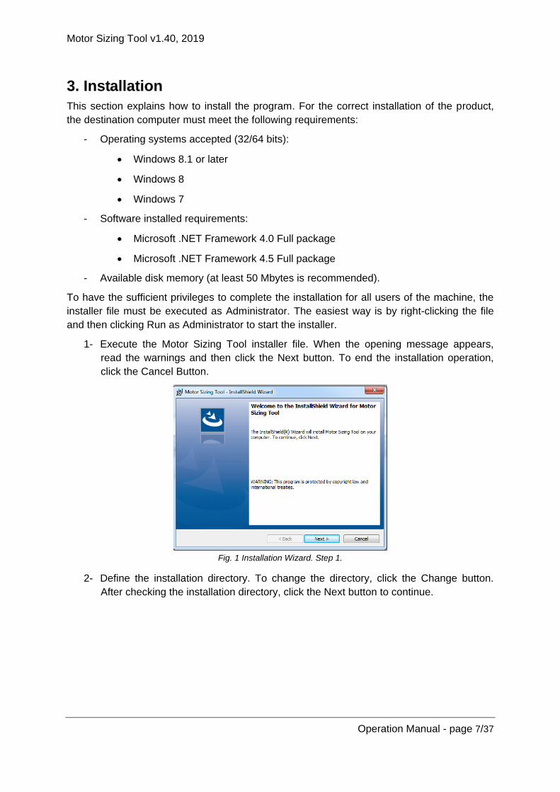
1- Execute the Motor Sizing Tool installer file. When the opening message appears,
read the warnings and then click the Next button. To end the installation operation,
click the Cancel Button.
Fig. 1 Installation Wizard. Step 1.
2- Define the installation directory. To change the directory, click the Change button.
After checking the installation directory, click the Next button to continue.

Motor Sizing Tool v1.40, 2019
Operation Manual - page 8/37
Fig. 2 Installation Wizard. Step 2.
3- Recheck all the information for copying the program files. If anything needs to be
changed, click the Back button. If no changes are required, click the Install button to
continue.
Fig. 3 Installation Wizard. Step 3.
4- When the installation is successfully completed, the following message appears.
Fig. 4 Installation Wizard. Step 4.
Motor Sizing Tool v1.40, 2019
Operation Manual - page 9/37
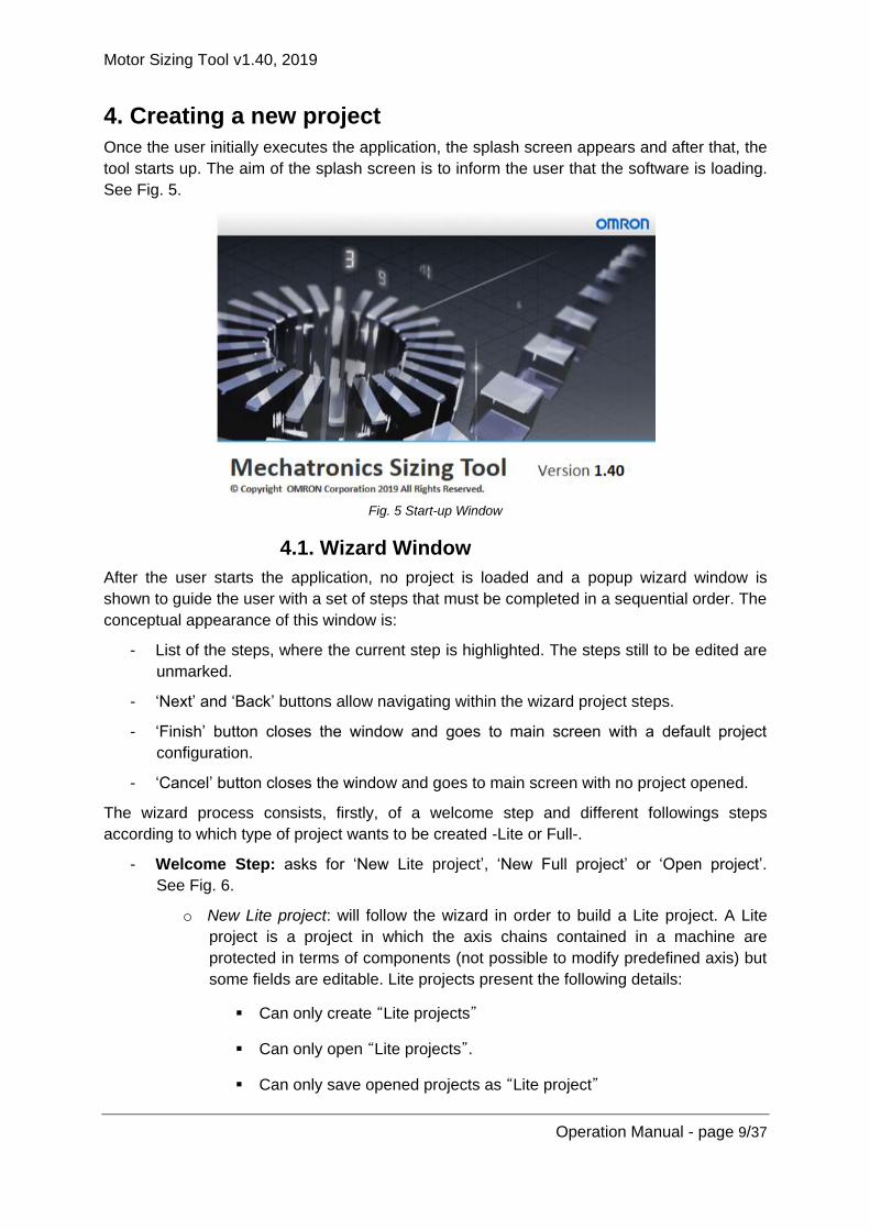
4. Creating a new project
Once the user initially executes the application, the splash screen appears and after that, the
tool starts up. The aim of the splash screen is to inform the user that the software is loading.
See Fig. 5.
Fig. 5 Start-up Window
4.1. Wizard Window
After the user starts the application, no project is loaded and a popup wizard window is
shown to guide the user with a set of steps that must be completed in a sequential order. The
conceptual appearance of this window is:
- List of the steps, where the current step is highlighted. The steps still to be edited are
unmarked.
- ‘Next’ and ‘Back’ buttons allow navigating within the wizard project steps.
- ‘Finish’ button closes the window and goes to main screen with a default project
configuration.
- ‘Cancel’ button closes the window and goes to main screen with no project opened.
The wizard process consists, firstly, of a welcome step and different followings steps
according to which type of project wants to be created -Lite or Full-.
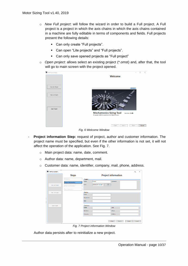
- Welcome Step: asks for ‘New Lite project’, ‘New Full project’ or ‘Open project’.
See Fig. 6.
o New Lite project: will follow the wizard in order to build a Lite project. A Lite
project is a project in which the axis chains contained in a machine are
protected in terms of components (not possible to modify predefined axis) but
some fields are editable. Lite projects present the following details:
Can only create “Lite projects”
Can only open “Lite projects”.
Can only save opened projects as “Lite project”
Motor Sizing Tool v1.40, 2019
Operation Manual - page 10/37
o New Full project: will follow the wizard in order to build a Full project. A Full
project is a project in which the axis chains in which the axis chains contained
in a machine are fully editable in terms of components and fields. Full projects
present the following details:
Can only create “Full projects”.
Can open “Lite projects” and “Full projects”.
Can only save opened projects as “Full project”
o Open project: allows select an existing project (*.omst) and, after that, the tool
will go to main screen with the project opened.
Fig. 6 Welcome Window
- Project information Step: request of project, author and customer information. The
project name must be specified, but even if the other information is not set, it will not
affect the operation of the application. See Fig. 7.
o Main project data: name, date, comment.
o Author data: name, department, mail.
o Customer data: name, identifier, company, mail, phone, address.
Fig. 7 Project information Window
Author data persists after to reinitialize a new project.
Motor Sizing Tool v1.40, 2019
Operation Manual - page 11/37
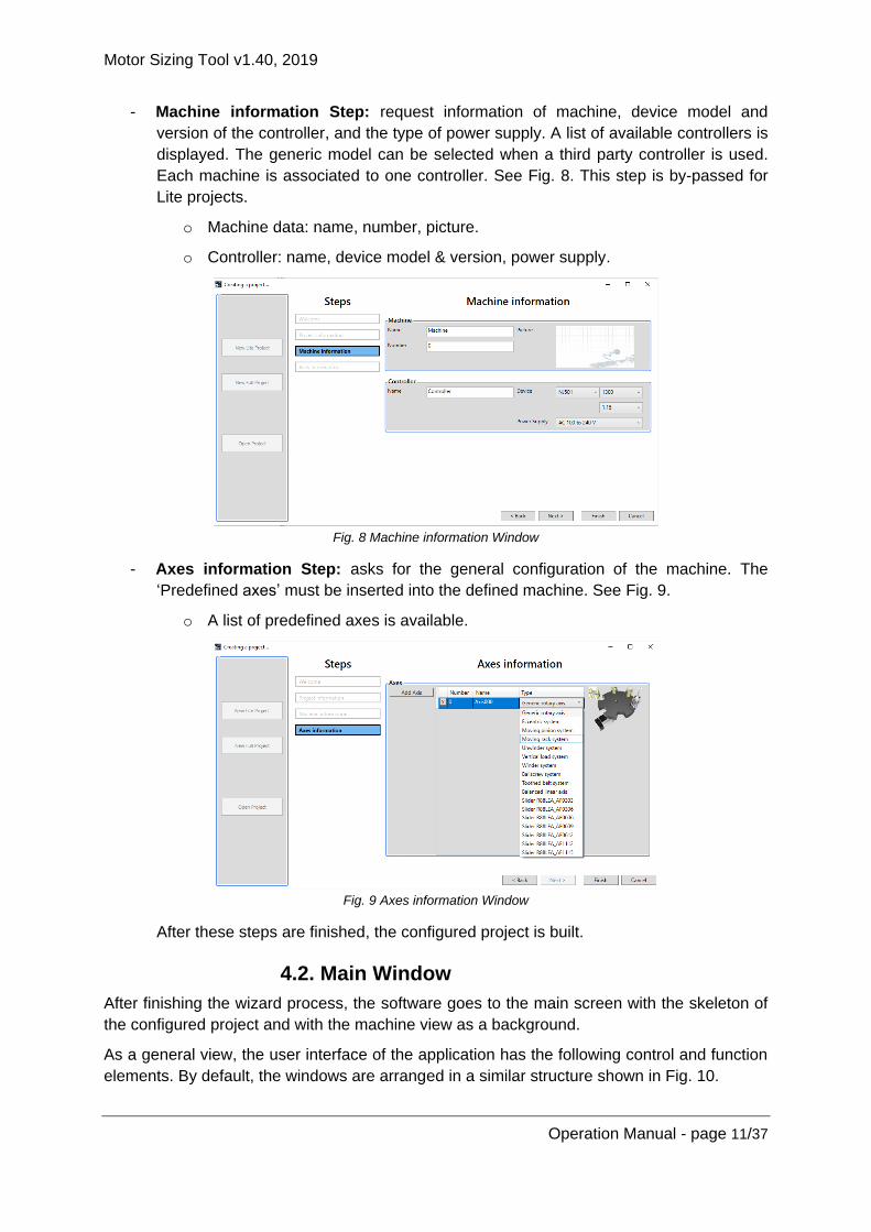
- Machine information Step: request information of machine, device model and
version of the controller, and the type of power supply. A list of available controllers is
displayed. The generic model can be selected when a third party controller is used.
Each machine is associated to one controller. See Fig. 8. This step is by-passed for
Lite projects.
o Machine data: name, number, picture.
o Controller: name, device model & version, power supply.
Fig. 8 Machine information Window
- Axes information Step: asks for the general configuration of the machine. The
‘Predefined axes’ must be inserted into the defined machine. See Fig. 9.
o A list of predefined axes is available.
Fig. 9 Axes information Window
After these steps are finished, the configured project is built.
4.2. Main Window
After finishing the wizard process, the software goes to the main screen with the skeleton of
the configured project and with the machine view as a background.
As a general view, the user interface of the application has the following control and function
elements. By default, the windows are arranged in a similar structure shown in Fig. 10.

Motor Sizing Tool v1.40, 2019
Operation Manual - page 12/37
For Full projects two tool anchorable toolbars will be available at top right: Axis toolbox and
Machine toolbox. In case of Lite projects, the Axis toolbox is not available, and the Machine
toolbox is always shown.
Fig. 10 Main window
It’s possible to create customizable layouts. By clicking and dragging, the windows can be
docked, undocked, floated, auto-hidden, or moved to new locations. Next Fig. 11 shows this
functionality.
Fig. 11 Dockable windows
4.2.1. Toolbar
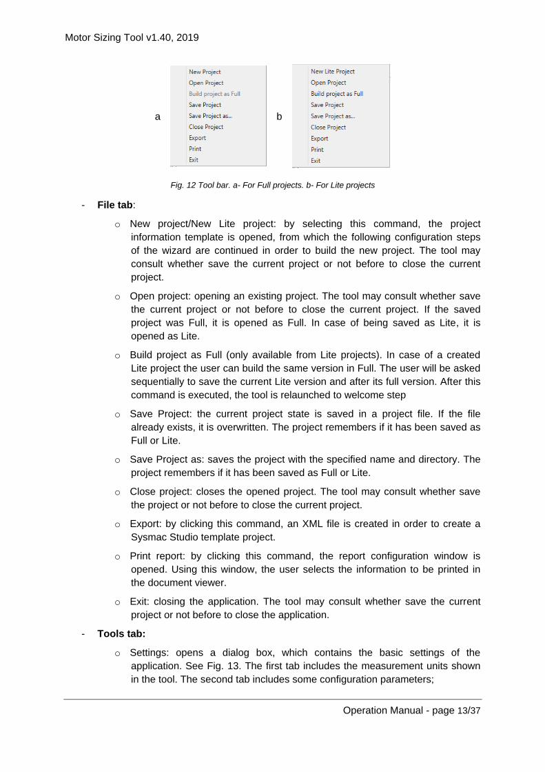
By clicking the items in the toolbar, which is partially shown in Fig. 12, the user can directly
invoke the most frequently used functions. The toolbar is split in three tabs.
Motor Sizing Tool v1.40, 2019
Operation Manual - page 13/37
a
b
Fig. 12 Tool bar. a- For Full projects. b- For Lite projects
- File tab:
o New project/New Lite project: by selecting this command, the project
information template is opened, from which the following configuration steps
of the wizard are continued in order to build the new project. The tool may
consult whether save the current project or not before to close the current
project.
o Open project: opening an existing project. The tool may consult whether save
the current project or not before to close the current project. If the saved
project was Full, it is opened as Full. In case of being saved as Lite, it is
opened as Lite.
o Build project as Full (only available from Lite projects). In case of a created
Lite project the user can build the same version in Full. The user will be asked
sequentially to save the current Lite version and after its full version. After this
command is executed, the tool is relaunched to welcome step
o Save Project: the current project state is saved in a project file. If the file
already exists, it is overwritten. The project remembers if it has been saved as
Full or Lite.
o Save Project as: saves the project with the specified name and directory. The
project remembers if it has been saved as Full or Lite.
o Close project: closes the opened project. The tool may consult whether save
the project or not before to close the current project.
o Export: by clicking this command, an XML file is created in order to create a
Sysmac Studio template project.
o Print report: by clicking this command, the report configuration window is
opened. Using this window, the user selects the information to be printed in
the document viewer.
o Exit: closing the application. The tool may consult whether save the current
project or not before to close the application.
- Tools tab:
o Settings: opens a dialog box, which contains the basic settings of the
application. See Fig. 13. The first tab includes the measurement units shown
in the tool. The second tab includes some configuration parameters;

Motor Sizing Tool v1.40, 2019
Operation Manual - page 14/37
Region of the accessories linked with the motor and drive selection
(Europe, Japan, America, China, Taiwan, Southeast Asia/India/Pacific
or Korea).
Step time and maximum number of points used in the dynamic brake
stop functionality when its calculation is launched.
Embed images option allows to save images into the project file when it
is saved.
Fig. 13 Settings
o Select language: changes the language of the user interface. English, Spanish,
French, Italian, German, Japanese, Korean, Chinese Simple and Chinese Traditional
can be selected.
o Inertia estimation method: Two inertia criteria are available.
0. By max inertia ratio method. Same as in versions previous to MST v1.30.
• In the Application results/Results tab, on row concerning Inertia &
Columns (3) and (4) it is shown Max. Inertia Ratio (data from motor)
and Inertia ratio (ratio application reduced inertia to the motor over
motor inertia), respectively.
Fig. 14 Application results/Results tab
• In the Device Selection/Motor List appears same information as
previous point but showed in the Max. Inertia Ratio column and as
tooltip once the cursor is on a specific motor.
Motor Sizing Tool v1.40, 2019
Operation Manual - page 15/37
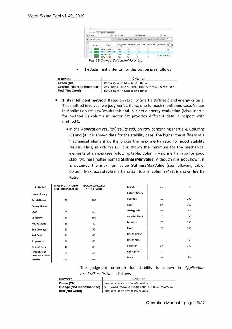
Fig. 15 Device Selection/Motor List
• The Judgment criterion for this option is as follows
Judgment Criterion
Green (OK) Inertia ratio <= Max. Inertia Ratio
Orange (Not recommended) Max. Inertia Ratio < Inertia ratio < 2*Max. Inertia Ratio
Red (Not Good) Inertia ratio >= Max. Inertia Ratio
1. By intelligent method. Based on stability (inertia stiffness) and energy criteria.
This method involves two judgment criteria, one for each mentioned case. Values in Application results/Results tab and in Kinetic energy evaluation (Max. inertia for method 0) column at motor list provides different data in respect with method 0.
• In the Application results/Results tab, on row concerning Inertia & Columns
(3) and (4) it is shown data for the stability case. The higher the stiffness of a
mechanical element is, the bigger the max inertia ratio for good stability
results. Thus, in column (3) it is shown the minimum for the mechanical
elements of an axis (see following table, Column Max. inertia ratio for good
stability), hereinafter named StiffnessMinValue. Although it is not shown, it
is obtained the maximum value StiffnessMaxValue (see following table,
Column Max. acceptable inertia ratio), too. In column (4) it is shown Inertia
Ratio.
ELEMENT MAX. INERTIA RATIO FOR GOOD STABILITY
MAX. ACCEPTABLE I NERTIA RATIO
Linear-Rotary
Rack&Pinion 30 100
Rotary-Linear
CAM 25 60
Ballscrew 30 100
Nut Rotating 25 80
Belt Conveyor 20 50
Roll feed 30 60
Suspension 30 60
Pinion&Rack 40 80
Pinion&Rack (moving pinion)
25 60
Winder 50 500
Cranck 25 60
Rotary-Rotary
Gearbox 100 200
Gear 60 120
Timing Belt 40 80
Cylinder block 100 150
Eccentric 100 150
Block 100 150
Linear-Linear
Linear Mass 100 150
Balancer 80 130
Axis carrier -- --
Lever 40 80
- The judgment criterion for stability is shown in Application
results/Results tab as follows Judgment Criterion
Green (OK) Inertia ratio <= StiffnessMinValue
Orange (Not recommended) StiffnessMinValue < Inertia ratio < StiffnessMaxValue
Red (Not Good) Inertia ratio >= StiffnessMaxValue

Motor Sizing Tool v1.40, 2019
Operation Manual - page 16/37
- In the Device Selection/Motor List appears energy related data. In the Kinetic
energy evaluation column appears the maximum absorbable energy from the
motor viewpoint. This value is computed as Ek_max_motor = ½ *
Jmotor*(1+MaxJratio) * W2max motor, where Jmotor is the Motor inertia, MaxJratio is
Max. Inertia Ratio and W2max motor is the maximum angular speed of the motor.
As tooltip it is represented the ratio Ek_max over Ek_max_motor in percentage.
Ek_max represents the maximum energy to the drive and is computed as Ek_max
= ½*Jtotal* W2max app, where Jtotal is the reduced axis inertia to the motor and
W2max app is the maximum angular speed of the pre-defined profile. Note:
Some special consideration is done for axis with winders/unwinders where it
is computed the worst energy case (max speed or max energy during the
movement).
- The judgment criterion for stability is shown in Device
Selection/Motor List as follows Judgment Criterion
Green (OK) Ek_max <= 0.9*Ek_max_motor
Orange (Not recommended)
0.9*Ek_max_motor < Ek_max < Ek_max_motor
Red (Not Good) Ek_max >= Ek_max_motor
- Help tab:
o Help file: opens the manual/help file of the tool.
o About this program: opens a popup window showing the version number and
some information about the application. See Fig. 16.
Fig. 16 About this program window
4.2.2. Solution Explorer
The project tree window, as an expandable tree view of the machine, classifies all the
elements included into the current project, which are machines and axes.

Motor Sizing Tool v1.40, 2019
Operation Manual - page 17/37
Fig. 17 Solution Explorer window
All the elements inserted in the project will be listed hierarchically, as the example shown in
Fig. 17.
All items are selectable, so by left clicking, its information appears in the property grid
window.
By double left clicking a machine or axis, the corresponding window is opened.
By right-clicking one item, a popup menu is opened. Depending of the item, the selecting
commands are:
- Project item:
o Add Machine
- Machine item:
o Add:
New Axis: adds a new empty axis.
Existing item: allows adding a previously saved axis from a selectable
file (*.axis.xml).
Predefined item: allows adding a predefined item.
o Paste: allows including a previously copied item inside the current machine.
o Delete
- Axis item
o Save as: allows saving the item in a file, which can be used into the same or
another project.
o Copy: creates a duplication of this item, which can be pasted inside the same
or another machine.
o Delete
Each item has a green/orange icon associated in order to warn of a well-configured or a non-
configured item, and by moving the mouse over an axis item, a tooltip displays the status.
See Fig. 18.

Motor Sizing Tool v1.40, 2019
Operation Manual - page 18/37
Fig. 18 Solution Explorer item status
The possible statuses for the axis are listed below:
- Axis is Ok
- Any linked axis is incorrect (when a group axes is defined).
- Axis without profile defined
- Axis without motor selected
- Axis without motor defined
- Axis without mechanical elements defined
- Axis without drive selected
- Axis without connection between motor and profile
- Axis with more than one profile defined
- Axis with more than one motor defined
- Axis is empty
- Axis elements connection mismatched
- Link required between integrated motor and power supply.
The machine is well-configured when all the inside elements, are also well-configured.
4.2.3. Property Grid
This window is used to view and edit the design-time properties of selected items that are
located into the workspace of the tool. It includes edit boxes, drop-down lists and other
controls to facilitate the configuration of the all items. Some properties may be read-only.
When one property is edited, the tool updates the linked properties and the calculations.
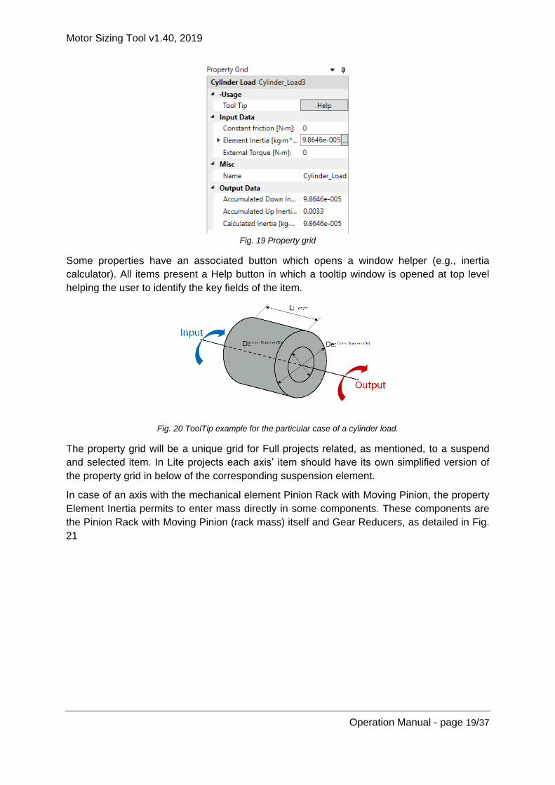
Fig. 19 shows the property grid when a cylinder load element is selected. Input data, Output
data and miscellaneous information are split.
Motor Sizing Tool v1.40, 2019
Operation Manual - page 19/37
Fig. 19 Property grid
Some properties have an associated button which opens a window helper (e.g., inertia
calculator). All items present a Help button in which a tooltip window is opened at top level
helping the user to identify the key fields of the item.
Fig. 20 ToolTip example for the particular case of a cylinder load.
The property grid will be a unique grid for Full projects related, as mentioned, to a suspend
and selected item. In Lite projects each axis’ item should have its own simplified version of
the property grid in below of the corresponding suspension element.
In case of an axis with the mechanical element Pinion Rack with Moving Pinion, the property
Element Inertia permits to enter mass directly in some components. These components are
the Pinion Rack with Moving Pinion (rack mass) itself and Gear Reducers, as detailed in Fig.
21

Motor Sizing Tool v1.40, 2019
Operation Manual - page 20/37
a
b
Fig. 21 Property grid Element Inertia detail. a. Axis without Pinion Rack with Moving Pinion. b. Axis with Pinion
Rack with Moving Pinion
4.2.4. Workspace and toolboxes
The workspace consists in a background with the general view of the project. Multiple tabs
can be opened, so the user selects the active one. By double clicking an item in the Solution
Explorer, the corresponding tab is opened.
- Machine tab:
o Includes the machine picture background with axes on top. The picture can be
modified from machine property grid.
o Axes and power supply can be dragged and dropped from the machine
toolbox. This toolbox loads the axes included in
“…User/MyDocuments/MotorSizingTool/AxesToolbox” folder.
o Items can be moved and resized.
o By double clicking an axis icon, the corresponding tab is opened.
o By left clicking an element, it will be selected and displayed in the property grid.
‘Supr’ keyboard deletes the selected item.
o Each machine is associated with one controller, so this element can be
modified but not removed.
- Axis tab:
o The axis tabs have clear differences according to if a Lite or Full project is
created.
Both project types include the background where the kinematic chain
with the mechanical elements, the motor and profile are built.
o The auto-alignment button (see Fig. 22) allows to align mechanical elements
as follows:
If no elements, Auto-align command has no effect

Motor Sizing Tool v1.40, 2019
Operation Manual - page 21/37
If no motor, all other items are aligned
In case of multiple sub-chains in the canvas, each one is auto-aligned
and located one below the other. If also exists alone mechanical items
in the canvas they are also align at the most bottom line
Fig. 22 Auto-align button
o The auto-connect button allows to connect mechanical elements (see Fig. 23). The Target is to create one unique valid kinematic chain that starts with a motor, has several mechanical elements and ends with a profile. The connection criterion is as follows:
If there is already a valid kinematic chain, no action will be done, and if
there are some non-connected elements, they will remain unconnected.
If there are already some pre-connected elements, this link will be
respected (for example, connected gearbox and ballscrew will behave
as a unique element that is rotary input and linear output).
First element is the motor. If there are several motors, the criteria are:
• Priority is: Omron rotary→Omron linear→Third party rotary→Third party rotary if there are rotary and linear elements to be connected.
• In case there are more than one motors of same type, the priority is by proximity to the top-left corner.
Last element is the profile.
• In case there are several profiles the priority is by proximity to the top-left corner.
• Profiles other than the non priority one will keep unconnected. Elements after a rotary motor follow next priority:
• Gearbox (only the closer to top-left corner if several gearboxes)
• Other rotary-to-rotary elements by proximity to the top-left corner.
• Rotary to linear elements. Only the element closer to the top-left corner.
• Linear to linear elements by proximity to the top-left corner.
Fig. 23 Auto-connect button
Full axis tab
o Includes ‘Application Results’ and ‘Devices Selection’ windows in the
bottom.
o The mechanical elements can be dragged and dropped from the axis
toolbox.

Motor Sizing Tool v1.40, 2019
Operation Manual - page 22/37
o By right clicking an item, a commands menu is opened and the plots tab
can be opened.
o By moving the mouse over an item, four visual elements will appear at
each side of the item. By clicking them with the left mouse button and start
dragging, an arrow is created to connect two elements.
o The elements can be connected, if the movement type between them is
compatible. The direction of the connections must be from motor to load.
o By left clicking an element, it will be selected and displayed in the property
grid. ‘Supr’ keyboard deletes the selected item.
Fig. 24 Axis tab for full projects
Lite axis tab
o Only can be loaded predefined valid axis. Any pre-saved axis that contains
a mechanical CAM, lever, linear balancer, crank, gantry and XY coupling
will trigger a pop-up message indicating an incompatibility with Lite project
type.
o ‘Devices Selection’ windows in the bottom that embeds Results summary.
o By moving the mouse over an item, four visual elements will appear at
each side of the item. However, axis cannot be modified, even in terms of
adding or remove current elements.
o Each element disposes of a simplified version of its equivalent version in
Full in below. If the element is displaced to another position, the property
grid will follow the item.
o If a profile is in the chain, the scope property permits to select to see
position, speed (default) or acceleration. To change the profile instruction,
double-click on the profile should be done. Number of instruction
Motor Sizing Tool v1.40, 2019
Operation Manual - page 23/37
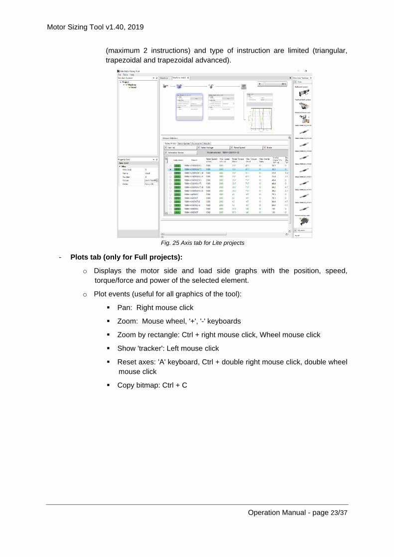
(maximum 2 instructions) and type of instruction are limited (triangular,
trapezoidal and trapezoidal advanced).
Fig. 25 Axis tab for Lite projects
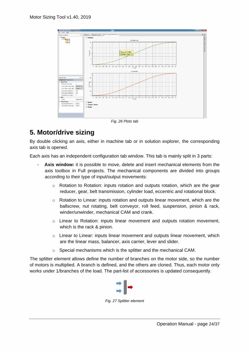
- Plots tab (only for Full projects):
o Displays the motor side and load side graphs with the position, speed,
torque/force and power of the selected element.
o Plot events (useful for all graphics of the tool):
Pan: Right mouse click
Zoom: Mouse wheel, '+', '-' keyboards
Zoom by rectangle: Ctrl + right mouse click, Wheel mouse click
Show 'tracker': Left mouse click
Reset axes: 'A' keyboard, Ctrl + double right mouse click, double wheel
mouse click
Copy bitmap: Ctrl + C
Motor Sizing Tool v1.40, 2019
Operation Manual - page 24/37
Fig. 26 Plots tab
5. Motor/drive sizing
By double clicking an axis, either in machine tab or in solution explorer, the corresponding
axis tab is opened.
Each axis has an independent configuration tab window. This tab is mainly split in 3 parts:
- Axis window: it is possible to move, delete and insert mechanical elements from the
axis toolbox in Full projects. The mechanical components are divided into groups
according to their type of input/output movements:
o Rotation to Rotation: inputs rotation and outputs rotation, which are the gear
reducer, gear, belt transmission, cylinder load, eccentric and rotational block.
o Rotation to Linear: inputs rotation and outputs linear movement, which are the
ballscrew, nut rotating, belt conveyor, roll feed, suspension, pinion & rack,
winder/unwinder, mechanical CAM and crank.
o Linear to Rotation: inputs linear movement and outputs rotation movement,
which is the rack & pinion.
o Linear to Linear: inputs linear movement and outputs linear movement, which
are the linear mass, balancer, axis carrier, lever and slider.
o Special mechanisms which is the splitter and the mechanical CAM.
The splitter element allows define the number of branches on the motor side, so the number
of motors is multiplied. A branch is defined, and the others are cloned. Thus, each motor only
works under 1/branches of the load. The part-list of accessories is updated consequently.
Fig. 27 Splitter element
Motor Sizing Tool v1.40, 2019
Operation Manual - page 25/37
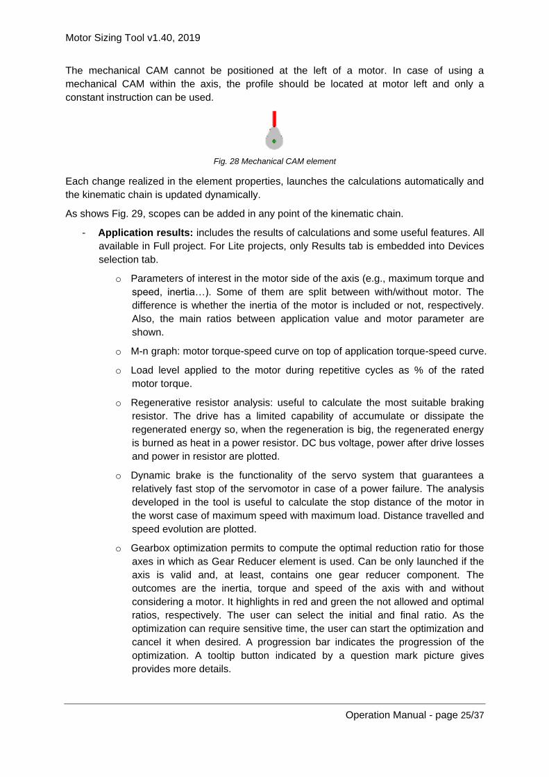
The mechanical CAM cannot be positioned at the left of a motor. In case of using a
mechanical CAM within the axis, the profile should be located at motor left and only a
constant instruction can be used.
Fig. 28 Mechanical CAM element
Each change realized in the element properties, launches the calculations automatically and
the kinematic chain is updated dynamically.
As shows Fig. 29, scopes can be added in any point of the kinematic chain.
- Application results: includes the results of calculations and some useful features. All
available in Full project. For Lite projects, only Results tab is embedded into Devices
selection tab.
o Parameters of interest in the motor side of the axis (e.g., maximum torque and
speed, inertia…). Some of them are split between with/without motor. The
difference is whether the inertia of the motor is included or not, respectively.
Also, the main ratios between application value and motor parameter are
shown.
o M-n graph: motor torque-speed curve on top of application torque-speed curve.
o Load level applied to the motor during repetitive cycles as % of the rated
motor torque.
o Regenerative resistor analysis: useful to calculate the most suitable braking
resistor. The drive has a limited capability of accumulate or dissipate the
regenerated energy so, when the regeneration is big, the regenerated energy
is burned as heat in a power resistor. DC bus voltage, power after drive losses
and power in resistor are plotted.
o Dynamic brake is the functionality of the servo system that guarantees a
relatively fast stop of the servomotor in case of a power failure. The analysis
developed in the tool is useful to calculate the stop distance of the motor in
the worst case of maximum speed with maximum load. Distance travelled and
speed evolution are plotted.
o Gearbox optimization permits to compute the optimal reduction ratio for those
axes in which as Gear Reducer element is used. Can be only launched if the
axis is valid and, at least, contains one gear reducer component. The
outcomes are the inertia, torque and speed of the axis with and without
considering a motor. It highlights in red and green the not allowed and optimal
ratios, respectively. The user can select the initial and final ratio. As the
optimization can require sensitive time, the user can start the optimization and
cancel it when desired. A progression bar indicates the progression of the
optimization. A tooltip button indicated by a question mark picture gives
provides more details.

Motor Sizing Tool v1.40, 2019
Operation Manual - page 26/37
Fig. 29 Axis window for Full projects
- Devices selection tabs: allows motor, drive and accessories selection. All the
information displayed is contained in the database.
o Motor selection: displays a list of the selectable motors, which can be modified
using the selection filters of family, voltage, speed and brake. Different list
boxes permit to filter according to four criteria; motor family, rated voltage,
rated speed, brake or judgment criteria result. Each motor has a judgement
according to the criteria below (with default criteria setting):
OK (green): motor that matches the requirements.
Not Good (red): the motor torque-speed curves are smaller than the
required by the application or Jload > 2Jmax.
Warning (orange): the motor torque-speed curves are OK for the
application but there are other criteria that do not match like excessive
inertia ratio (Jload < 2Jmax and Jload > Jmax) or overload level
warning.
o Drive selection: after the preselection motor model, the final motor model
name is defined according to the encoder, oil seal, shaft and connector
selected. After that, the corresponding list of selectable drives is shown.
o Accessories selection: after motor and drive selection, the part-list of
accessories is created. When the accessory is a cable, the length is
selectable. The selected accessories will be added to the part-list.
Motor Sizing Tool v1.40, 2019
Operation Manual - page 27/37
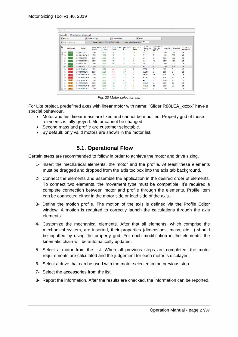
Fig. 30 Motor selection tab
For Lite project, predefined axes with linear motor with name: “Slider R88LEA_xxxxx” have a special behaviour.
• Motor and first linear mass are fixed and cannot be modified. Property grid of those elements is fully greyed. Motor cannot be changed.
• Second mass and profile are customer selectable.
• By default, only valid motors are shown in the motor list.
5.1. Operational Flow
Certain steps are recommended to follow in order to achieve the motor and drive sizing.
1- Insert the mechanical elements, the motor and the profile. At least these elements
must be dragged and dropped from the axis toolbox into the axis tab background.
2- Connect the elements and assemble the application in the desired order of elements.
To connect two elements, the movement type must be compatible. It’s required a
complete connection between motor and profile through the elements. Profile item
can be connected either in the motor side or load side of the axis.
3- Define the motion profile. The motion of the axis is defined via the Profile Editor
window. A motion is required to correctly launch the calculations through the axis
elements.
4- Customize the mechanical elements. After that all elements, which comprise the
mechanical system, are inserted, their properties (dimensions, mass, etc…) should
be inputted by using the property grid. For each modification in the elements, the
kinematic chain will be automatically updated.
5- Select a motor from the list. When all previous steps are completed, the motor
requirements are calculated and the judgement for each motor is displayed.
6- Select a drive that can be used with the motor selected in the previous step.
7- Select the accessories from the list.
8- Report the information. After the results are checked, the information can be reported.

Motor Sizing Tool v1.40, 2019
Operation Manual - page 28/37
Fig. 31 Axis carrier element
Group axes are a special case of motor/drive sizing in the tool. In order to have an intuitive
representation of group axes, there is defined one element called ‘Axis carrier’, which
represents one axis in top of another. This is especially useful when all the elements of the
mechanical chain cannot be represented in a plane (e.g., gantry system or XYZ system).
When an axis is on top of the other axis, this will be represented in different tabs (e.g., Y axis
on top of the gantry, then gantry axis will include the ‘axis carrier’, which indicates that gantry
carries Y axis). Fig. 32 shows the hierarchical structure of a group axes in the Solution
Explorer.
Fig. 32 Axes group in Solution Explorer
5.2. Profile Editor
By right clicking the profile item and selecting ‘Open Editor Profile Window’, or double-
clicking the item, the profile editor is opened. See Fig. 33 for Full projects.
The motion profile describes how the mechanical application should move. This window
allows define the motion by segments.
By clicking the ‘Add instruction’ button, a segment is added after the initial row, of which the
initial speed can be edited. The selectable instructions are:
- Constant: keeps initial speed for the selected time. Only duration is selectable.
- Ramp: starting from the initial position and speed, it will have always linear velocity,
i.e. constant acceleration. Selectable items are time (always) and one of the next; (I)
final position (then, speed and acceleration are calculated), (II) final speed (then,
position and acceleration are calculated) or (III) acceleration (then, final position and
speed are calculated).
o A field S-curve time can be edited in order to add a trapezoidal acceleration
behaviour. The S-curve time defines the acceleration (symmetrical for
deceleration) time.
If S-curve time is 0 → Linear ramp with no S behaviour
If S-curve time is Instruction duration/2 →Only S, no linear part.
The S-ramp is symmetrical
- Import: allows adding a profile from *.csv table (slave position vs time or slave
position vs master position). According to the typical rules used in CSV files, when
the decimal separator is a point then the default CSV separator will be a comma, but

Motor Sizing Tool v1.40, 2019
Operation Manual - page 29/37
if the decimal separator is a comma, then the default CSV separator will be a
semicolon. Both formats are accepted in the tool. Imported values can be averaged if
the user enables the filter.
- Brake: keep initial position for the selected duration.
- Predefined triangular profile + dwell.
- Predefined trapezoidal 1/3 profile + dwell.
- Predefined advanced trapezoidal profile + dwell. The motion profile permits to define
can define separately:
o Acceleration/Deceleration section in time or rate
o Total duration and distance of the movement.
o Depending on how data is entered the complementary section can be
recomputed to obtain a consistent solution (note that in case of using rate
control type could imply more than one solution. Then the tool proposes one
as closes as possible to user inputs).
By selecting a segment, its properties can be configured. For each modification in the
segment, the profile is automatically updated. Besides, each segment has some read only
information:
- Duration
- Final position/ speed / acceleration of the corresponding segment (read only).
At the bottom of the window, the position, speed, and acceleration of the edited profile are
shown.
By selecting the mechanical element, it’s possible to show the effect of this profile in another
element of the axis. The step time between points will be automatically calculated by the tool
using an intelligent algorithm, in order to optimize the step increment compared to the
duration of the profile.
Finally, OK and Cancel buttons, accept or discard the modifications.
Fig. 33 Profile editor window for Full projects

Motor Sizing Tool v1.40, 2019
Operation Manual - page 30/37
In case of Lite projects, the Profile editor is limited to two instructions. It is not possible to add or delete instructions. Also, selectable instructions are limited to Ramp, Trapezoidal or Trapezoidal Advanced.
Fig. 34 Profile editor window for Lite projects
5.3. Inertia calculator
The inertia calculator provides a helper to calculate the inertia value for an element. This
window is opened by clicking the button associated with the inertia properties in the property
grid. See Fig. 35.
Cylinder and cuboid solid figures are selectable. By defining the dimensions and density of
these elements, the corresponding inertia value is automatically calculated.
Predefined materials are selectable to define the density of the element. Otherwise, density
can be inserted manually.
By checking the ‘Direct Inertia Input’ field, the inertia calculator is disabled and the value of
the inertia can be defined manually in the corresponding edit box.
Fig. 35 Inertia editor window for Full projects
Motor Sizing Tool v1.40, 2019
Operation Manual - page 31/37
In case of Lite projects, some fields are not available. The not available field depends on the axis items. This kind of behaviour affects ball screw, nut rotating, rack pinion, gear, belt conveyor, belt transmission, suspension and winder/unwinder.
Fig. 36 Example of Inertia editor window for Lite projects corresponding to a belt conveyor
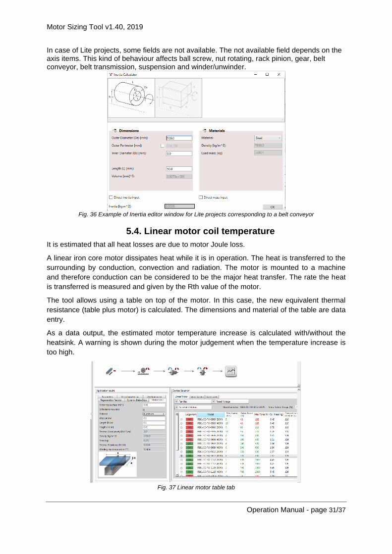
5.4. Linear motor coil temperature
It is estimated that all heat losses are due to motor Joule loss.
A linear iron core motor dissipates heat while it is in operation. The heat is transferred to the
surrounding by conduction, convection and radiation. The motor is mounted to a machine
and therefore conduction can be considered to be the major heat transfer. The rate the heat
is transferred is measured and given by the Rth value of the motor.
The tool allows using a table on top of the motor. In this case, the new equivalent thermal
resistance (table plus motor) is calculated. The dimensions and material of the table are data
entry.
As a data output, the estimated motor temperature increase is calculated with/without the
heatsink. A warning is shown during the motor judgement when the temperature increase is
too high.
Fig. 37 Linear motor table tab

Motor Sizing Tool v1.40, 2019
Operation Manual - page 32/37
6. Power supply tab
When an Integrated motor is selected, a link between the motor and a power supply is
required. The links are tied in the table shown on top of the machine tab, after a power
supply is included. This option is only available for Full projects.
By double clicking a power supply in the machine tab, the corresponding power supply tab is
opened. The current consumption of the power supply depends in the duty cycles of all the
axes fed by this. Once the current consumption of the associated axis has been done, an
alignment of the speed vs time graphs can be done, see Fig. 38.
- User can make a time shift for every motor graph.
- The profile for every motor is considered cyclic.
- User can modify the time period to show, as every motor profile has a different
duration.
Fig. 38 Power supply tab (I)
As output the tool gives the required AC current vs time, the peak AC current and the RMS
AC current. The supply voltage (400Vac default) is an input parameter. Finally, a judgement
is applied to the available power supplies, as shown in Fig. 39.
Fig. 39 Power supply tab (II)
Motor Sizing Tool v1.40, 2019
Operation Manual - page 33/37
7. Third party motors
The tool supports third party motors in Full projects. Two new icons (for rotary and linear third
party) are included in the axis toolbox in order to allow the use of these elements in the
kinematic chain.
Once the project is saved, the third party motor is embedded in the output file. Thus, in
another computer, the third party motors involved in the project can be exported and mixed
with local third party libraries. If the project is opened in a new computer, the following
behaviour can be observed:
- Create in Computer A a project with third party motor and open the project in
Computer B that does not have this motor. Result: New third party motor is added in
database in Computer B without dialogue.
- Create in Computer A a project with third party motor and open the project in
Computer B that already has this motor. Result: the project is opened in Computer B
without dialogue.
- Create in Computer A a project with third party motor and open the project in
Computer B that has a motor with same name but different data. Result: the project is
opened in Computer B with a dialogue that explains the conflict and offer to: (i) Update
existing database, (ii) Add as new motor or (iii) Cancel opening. The differences are
described in the dialogue.
When a third party motor is added to an axis, the selectable motors will not come from
database but from a library. This library consists in an *.xml file stored in a
“…User/MyDocuments/MotorSizingTool\ThirdParty” folder that defines the motor
characteristics.
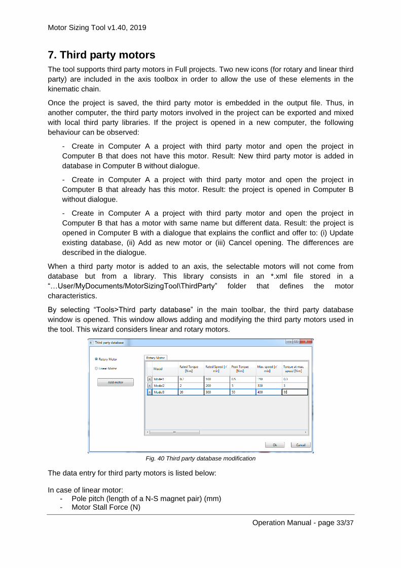
By selecting “Tools>Third party database” in the main toolbar, the third party database
window is opened. This window allows adding and modifying the third party motors used in
the tool. This wizard considers linear and rotary motors.
Fig. 40 Third party database modification
The data entry for third party motors is listed below: In case of linear motor:
- Pole pitch (length of a N-S magnet pair) (mm) - Motor Stall Force (N)

Motor Sizing Tool v1.40, 2019
Operation Manual - page 34/37
- Motor Stall current (Arms) - Motor Rated Force (N) - Motor rated speed (m/s) - Force at maximum speed (N) - Maximum speed (m/s) - Motor peak Force (N) - Coil mass (kg) - Per-phase inductance (mH) - Per-phase resistance (Ω) - Thermal time constant (s) - Power (W) - Motor mass (kg) - Max DC bus voltage acceptable - Description
In case of rotary motor:
- Number of pole pairs (--) - Motor Stall Torque (Nm) - Motor Stall current (Arms) - Motor Rated Torque (Nm) - Motor Rated Speed (rpm) - Torque at maximum speed (Nm) - Maximum speed (rpm) - Motor peak Torque (Nm) - Rotor inertia (Kg·m2 · 10-4) - Max. Inertia Ratio - Per-phase inductance (mH) - Per-phase resistance (Ω) - Thermal time constant (s) - Power (W) - Motor mass (kg) - Max DC bus voltage acceptable - Description
Fig. 41 shows the M-n curve, to correctly interpret the motor data entry.
Fig. 41 M-n curve of third party motors
When this window is closed, the external *.xml file is updated according to the modifications
applied.
Then, inside the axis tab, once a third party motor is included to the axis (by drag & drop the
corresponding icon from the toolbox), the list of selectable motors appears. This is the list of

Motor Sizing Tool v1.40, 2019
Operation Manual - page 35/37
motors included in the *.xml file, as defined above. A judgement is applied to the motors list
in order to guide the user when selecting one of them.
After a third party motor is selected by the user, the drive selection criteria are applied. The
selectable drives are the G5 linear servo drive EtherCAT family. These drives can support
linear and rotary motors. The criteria are:
- Drive rated output current >= Motor stall current
- Drive Peak Output current >= Application peak current
- Max frequency needed for max application speed < 500Hz (if this is not true, no drive
is valid).
- Max voltage needed < Drive supply-10%
After the calculations are applied by the tool, the user can select a drive which satisfies the
requirements, if any.
Finally, no accessories are selectable for third party motors.
Motor Sizing Tool v1.40, 2019
Operation Manual - page 36/37
8. Data output
At the end of the process, there are a couple of possibilities of data output:
- Print a document report, which is also exportable to *.doc, *.pdf and *.xls.
- Export an *.xml file to Sysmac Studio program.
Only the well-configured items can be exported. If the user is trying to export a non-
configured item, a warning message appears.
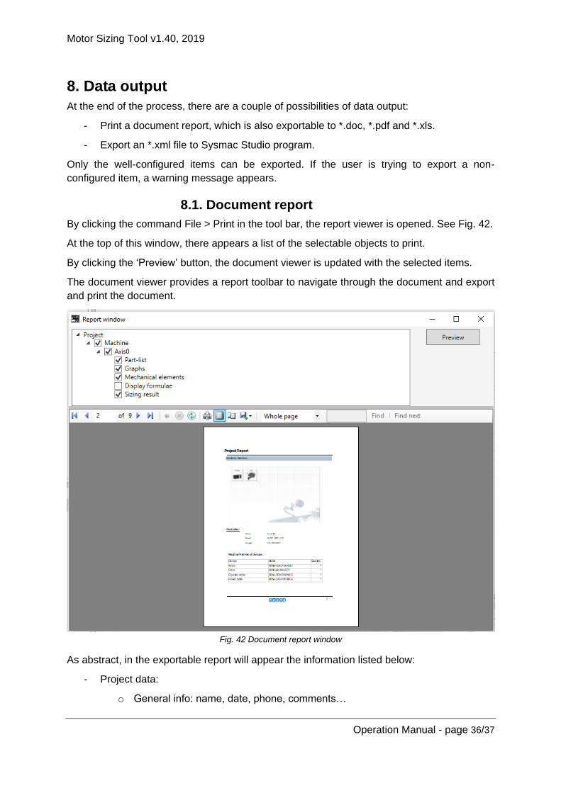
8.1. Document report
By clicking the command File > Print in the tool bar, the report viewer is opened. See Fig. 42.
At the top of this window, there appears a list of the selectable objects to print.
By clicking the ‘Preview’ button, the document viewer is updated with the selected items.
The document viewer provides a report toolbar to navigate through the document and export
and print the document.
Fig. 42 Document report window
As abstract, in the exportable report will appear the information listed below:
- Project data:
o General info: name, date, phone, comments…

Motor Sizing Tool v1.40, 2019
Operation Manual - page 37/37
o Customer info: name, company, address, mail, phone…
o Author info: name, department, mail…
- Machine data
o General info: name, machine picture with the item icon on top.
o Controller information: model, version, power supply…
o Machine part-list of devices and accessories.
o Axes Data
General info: name, number…
Application Torque-speed curve on top of motor Torque-speed curve.
Motor motion profiles; torque, speed, power vs time.
Axis part-list of devices and accessories.
Display formulae.
8.2. Export file to Sysmac Studio
By clicking ‘File > Export’ in the tool bar, an *.xml file is generated. As a data output, the
project developed using the Sizing Tool can be reused to create a Sysmac Studio template
project. To allow this, the output of the Sizing Tool should be able to export an *xml file with
the suitable structure:
- Project Property: name, date, author, comment…
- System Configuration: device information of controller and axes.
- NexAxis Settings: defines settings and parameters about the axes used in the sizing
tool.
- NexAxis Group Settings: defines settings and parameters about the group axes used
in the sizing tool.

2019
1219 (0616) I820-E1-04