motor speed sensing with pic microcontroller
TRANSCRIPT

Motor Speed Sensing with PIC Microcontroller Brandon Upchurch, Olivet Nazarene University
Faculty Advisor: Dr. Rodney Korthals, Olivet Nazarene University
Student Paper Abstract A system was designed and built to detect the speed and acceleration of a DC motor. Main components of the system were a single-chip microcontroller, a phototransistor and emitter, and a comparator. This system was designed to try to test the applications of a PIC chip processor. The abilities of the internal EEPROM memory of the microchip were also explored. Under the current class requirements of Olivet Nazarene University, the internal EEPROM was never explored, so this project was thought to be an excellent way to show students how the device can be applied in a real world system.
The system counted and stored fan motor blade crossing of the emitter/detector during 5ms intervals and stored the data to an internal EEPROM. The data was also displayed on an LED output for instant velocity monitoring. The EEPROM data can be read by the development tools and used to analyze the motor’s acceleration. This can be used in the Automatic Controls Laboratory work at Olivet Nazarene University, to characterize a DC-motor. This project could also be helpful in the building of the Mini-Baja Car project, which is a design project given for seniors at Olivet. A speed sensor is not in the necessary requirements for the design of the car, but it might be helpful to measure torque and acceleration for the project.
Key Words Student Paper, School of Professional Studies

Motor Speed Sensing with PIC Microcontroller Brandon Upchurch Olivet Nazarene University, Bourbonnais IL, 60914. Faculty Advisor: Dr. Rodney Korthals Objectives: The objective of this project was to build a circuit that could act as either an accelerometer or a speedometer for a DC motor; this data can be related to the position, speed and acceleration of the motor. This kind of data is extremely useful in robotics design, as this will give the user a more fixed control over a system. The circuit was to give counts of fan blades passing a photo-emitter-detector pair at fixed intervals. Dividing the fan blade crossing on a per second basis by the number of fan blades gives the fan’s speed. Background: This project builds on previous projects that introduce programming a PIC microprocessor (Microchip1 PIC16F88) and doing digital and analog inputs and outputs with the microcontroller units (MCUs). The first project introduces programming the PIC MCUs using MikroC2 and an EPIC3 serial-port PIC programmer. Along with using to software and programmer, the key skills the students practice with the first project are reading switches, setting outputs that drive light-emitting diodes (LEDs), and using built-in compiler time delay functions. Students doing these projects in a sophomore level Digital Systems class already have experience wiring digital Boolean function circuits with LEDs. Three aspects of setting up the PIC 16F88 MCUs need to be explained to the students in the first project. First, students need to learn how to use the TRISA and TRISB functions to set the pins on the PIC MCU as inputs or outputs. Second, they need to learn how to set up the compiler, programmer, and OSSCON register so the PIC works with its internal oscillator. Third, students need to be made aware of is how to set up the ANSEL register so the analog input pins are set to read digital values. The resulting first six lines of code in the main() function for using the PICs would like something like:
TRISA = 0xFF; //set port A as inputs
TRISB = 0; //this sets port B as ouputs
PORTB = 0; //This puts zeros on the port B outputs
OSCCON = 0x7A; //This sets the PIC internal oscillator
//to run at 8MHzANSEL = 0x00; //This sets
the digital/analog IO pins
//to operate as digital inputs
The students are then encouraged to look at examples that came with the compiler to
understand the delay_ms(X) function and use their C programming skills from their
previous semester’s programming class to read switches, set the output to mimic four of

the input switches, or run code making the lights “chase” like a marquee if a fifth input switch is set high. Phototransistor: Another project that precedes this one introduces the students to a photo-transistor and performing analog measurements with the PIC MCUs. The phototransistor circuit is used in this project with an infra-red LED emitter as an emitter-detector pair to identify fan-blade crossing. Results of one of these experiments are presented as background to using a comparator for this project. The schematic (Figure 1) shows how the phototransistor is used in a voltage divider. The phototransistor will turn the transistor on as light hits it, decreasing the voltage at Vout. Previous experiments with different resistors as part of the photo-transistor voltage divider circuit (Table 1) show that the resistor R should be as large as possible to increase sensitivity. Using the pattern shown by this experiment a resistor value of four Mega Ohms was chosen.
Figure 1. Phototransisotr in a voltage-divider
circuit used with an infra-red emitter to detect
fan blade crossings.
Table 1. Results from photodetector experiment showing Vo sensitivity for different resistance Ro.
Resistor kohm
Vo with normal light (Volts)
Vo in Dark (Volts)
10 6.36 6.42
20.02 6.3 6.41
29.89 6.22 6.4
42.4 6.15 6.39
49.7 6.12 6.39
60.1 6.06 6.38
68.3 5.95 6.38
84.1 5.91 6.37
88.1 5.87 6.36
101.5 5.75 6.36

PIC chip timer: The PIC 16F88 chip1 used has a built in oscillator that can operate at different speed from 137kH to 8Mhz depending on how the OSCCON register is set-up (see chip specs for PIC 16F88). It also has an interrupt counter byte TMR0 that counts from a specified number to 255 and then resets. The TMR0 counts at a ratio of the total oscillator speed that is set by the user with the OPTION_REG register. An interrupt function can be enabled to execute every time the TMR0 number rolls over from 255 to 0. This interrupt routine can in turn increase other counter variables (i.e. cnt) to achieve help schedule less frequent events. By programming a function checked by the main routine to execute whenever it reads that the interrupt counter (cnt) reaches a certain number (and then resets the cnt value to zero), the period between that function’s executing can be controlled. Establishing a regular clock in this manner and verifying its operation was part of this project’s goal. LMC 6482 OP-Amp4 Chip: The LMC 6482 Op-Amp chip is a rail op-amp that was used as a comparator. A comparator on an op-amp works like an op-amp with no feedback; the output of a comparator goes high whenever the positive input is greater than the negative side or goes low if the reverse is true. An adjustable potentiometer (trimpot) is connected to the high and low microprocessor power supply, and the adjustable pin of trimpot is connected to the negative input of the op-amp/comparator (Figure 2). The positive input of the op-amp is connected to the photodetector circuit (Figure 1). The trimpot is then adjusted to an average reading of the photodetector circuit. If the blades of the fan block the light from the photodetector, the voltage on the minus side is higher than the plus side and the op-amp will try to pull the voltage low, resulting in a “low” (0) output from the chip. If instead the photodetector is exposed to a lot of light, the minus side voltage is lower than the plus side of the comparator and the comparator will provide a “high” (1) output. This allows a small difference in analog voltages to be translated into a digital output without the using an Analog to Digital Converter (ADC).

DC Fan motor A DC fan has two wires, one for power and one for ground. As it is a simple motor, the more voltage put into the motor the more the speed of the fan will increase. The fan’s running voltage is about 3-8 Volts. This experiment tries to measure the fan speed by counting how often the fan blades pass between the photodetector circuit of Figure 1 and an infrared LED light source. By recording fan speeds over short (2-10ms) intervals and comparing speeds at different times, the motor’s acceleration can also be measured. Methods: The first task is to set-up the phototransistor sensor that will create a pulse every time a fan blade passes in front of the sensor. To do this an LED was placed on one side of the DC fan, and on the other side of the fan the phototransistor is hooked up in the same way as described in the background section. An oscilloscope will show how the phototransistor divider circuit output goes low every time a fan blade breaks the visual connection with the LED. This creates a rather regular square wave output; the only problem with this set-up is that the peak-to-peak difference between a high and a low value is only about 200mV, not significant enough for the ADC on a PIC chip to pick up (although this was tried; see discussion section). The solution to the problem of small voltage swings is a rail-to-rail op-amp. As was explained in the background section the op-amp is acting as a comparator in this case. Using a trimpot (that is a variable resistor), the “+” voltage was set at 145 mV (which was just a bit higher than the peak high voltage that represents something going in front of the phototransistor). Running the voltage out from the phototransistor into the “-” side, the comparator circuit was ready for testing. The output from the op-amp chip matched the phototransistor’s output, the only difference is that now the peak to peak
Figure 2. LMC 6482 rail-to-rail op-amp wired as a comparator.

voltage difference is closer to 6 volts of the battery-operated power supply, and the wave was both square (better for a signal), and inverted. The inverted output was expected since as the pulse goes higher than the set limit, the op-amp will try to drop voltage low and when the pulse goes lower it will set the voltage high. Now this square wave can be plugged into the PIC chip as a digital input. The next task is to program the PIC chip, telling it what to do with this signal when it receives it. Receiving the signal is not difficult, just assign a pin from PORTA to be an input pin and plug the input to that pin (see code and circuit schematic sections in the appendix). The chip should do one of two things. If set on speedometer mode the chip should collect data (number of times a fan blade comes in front of the sensor) for a certain time period and then immediately display it on the PORTB output pins. Alternatively, if the chip is on accelerometer mode than it has to collect data for a certain time period (same as the speedometer), and then store that data, and repeat this process a number of times. After it has that data it then has to display the gathered values in such a way as to be usable to the programmer. The first step in both speedometer and accelerometer processes is to count the number of fan blades per time period coming in. Ordinarily to count something one would just use a simple if statement, for example, if input is low, then make count = count+1. This is in error (see discussion section) because the chip cycles through the code many times a millisecond, which means (following the logic of the chip), it should count up one every time it reaches that if statement, which means hundreds of counts are collected when really the fan blade went by only once. One could try to fix the problem by using the delay function to wait a certain time period between each count, and certainly that would work for a preset voltage fan where the speed never changes. The problem here is that the fan is of variable voltage and so if the delay is set just high enough to count one fan blade at 8 volts, then turning it down to 3 volts will cause the delay to not go enough for the longer time period, and phantom counts will exist again. The actual solution to the problem is to think of it as a sequencing problem. What the program needs to do is count only when it sees a light spot then a dark spot and not count again until it sees another light spot and dark spot combo. This can be done with if statements as well, it just takes three instead of two. First, an if statement is set-up saying if input is high (that is the sensor sees a light spot), then set counter at zero. After that make another if statement that says if the input is low (sensor seeing a dark spot), then count up one. The third if statement says that if the count equals exactly two then count one spot (see code in appendix). By doing this it does not matter how many times the code cycles through per fan blade; the count will not go up until the fan sees a light spot then a dark spot. Alternatively, if the fan happens to start on a dark spot this will be counted to, since the original setting when the chip is turned on is already zero. This assumption was checked by replacing the count blade command with a PORTB= ~PORTB which will have the light turn on and off each time there would be a count, hooking this up to an oscilloscope and comparing it to the output of the phototransistor it was confirmed that the switches match up with peaks from the phototransistor.

The next was to build a timer that would gather these counts for a certain time period and either save them or immediately output them. This is where an interrupt function using the TMR0 is helpful. The time period determined for this particular experiment was 0.1 seconds, to do this you need a repeating pulse every 0.2 seconds. A 0.2 seconds per pulse ratio equals 5Hz. Using the equation listed in the background section of this report (to see how this equation was developed see the discussion section of this report), it was found that TMR0 should be set at 50, and cnt should be set at 236 for the clock to activate the timer as often as it should be. This value was checked on a universal counter/ timer, and the period to be 0.2 seconds, which represents a counting rate of 0.1 second. This discrepancy can be explained because of the testing process that was used to determine the necessary data-gathering period. The process consisted of hooking an LED to an extraneous output on the microcontroller and programming the microchip to toggle the LED every time data was collected. The universal counter/timer only measured the period between on peaks, and so the actual period is half of the measured period (this was double-checked on an oscilloscope and confirmed). This is where the program begins to divide itself into two programs. For the speedometer every time the cnt value hits 236 the cnt value should reset itself to zero and the fan blade counts (called counter) should display on the PORTB, and then counter is reset to zero to start the next count (Appendix Speedometer code). This gives a constant update of the number of counts per 100 milliseconds. To do the accelerometer an if statement that activates every 236 cnts will still clear both the count and the cnt values back to zero, but instead of displaying it the values are saved in an array value, and the next array value is measured and recorded the next time cnt equals 236. The program continues to do this until the array is full, and then breaks out of this
Read Input
Input?
Count =1?
Count=0 Increment Count
Increment Count
HighLow
Yes
No
Figure 3. Diagram of thought process to prevent multiple counts
per fan-blade crossing cycle.

loop and starts a new one which displays the values of the array one at a time with a ten second delay between each one (using the delay function). A third program was also built; this program is a proof program that outputs the frequencies of the sensor, the counter (by having PORTB turn on and off every time there should be a count), and the data collection counter (by having PORTA.F2 blink). This exists to facilitate verification of data collection frequency. Results/Discussion: There are many ways to go wrong in this particular project, many of which were discovered while working on the project. To prevent others from making these errors, many of them have been discussed in the following paragraphs. The first problem run into in this project was a strange slowness discovered in the internal clocking system. While all the specs say that the chip should have a 8Mhz internal processor, when it was checked (by giving the chip a simple blink function that should turn the light on and off as fast as it can) it showed to be running about 137 khz, which is extremely sluggish compared to the expected 8 Mhz. Some research into the chip specs of the PIC16F88 showed that there was an internal oscillator register that had to be set to the right value before the eight megahertz could be clocked. So it was discovered that the OSCCON register has to be set to 7A for the chip to run at full speed. Also needed for the project was the interrupt function required for reading the count time. This left me curious as to how to get the exact frequency I wanted by looking at an equation, so I took what I knew: there was a clock value set (OSCCON), there was a TMR0 number set, there was a cnt number set, and there was a ratio of the internal clock to TMR0 values to the internal timer. So the first equation I came up with looked something like this:
frequencycntRatiogOptionTMR
SettingClock 1
_Re_
1
0256
_. What I found though was that the
frequency the equation gave was about 8 times what it was when tested at low TMR0 values, and became even more unreliable as the TMR0 got higher. So I developed a way to be certain of the equation. What I did was hold constant the number of cnts (3), the option reg ratio (1/4), and the OSCCON values (at 4 Megahertz and 8 Megahertz) and decided to test ten different TMR0 functions for frequencies (Table 2).
Table 2. Frequency of interrupts for different clock rates and counts. Interrupts occur after counts roll-over at 256 after counting up from the given starting value.
TMR0 1 25 50 75 100 125 150 175 200 225
4 Mhz 159.5 176 196.8 223 258 305 373.7 482.5 681 1153
8 Mhz 319 351.3 393.22 446.3 515 610 747.5 965 1359 2305
Assuming a TMR0 function of 1 to be the most accurate (which makes sense as things get faster it may tend to run in to itself at some point) I ran the equation through with an

extra unknown variable: 5.1591
*3
1
4
1
1256
4
x
Mhz. The solution of this turned out to be
about 8.196. I did some testing to see if I could determine what this number represents, but without result. Having this variable adjusted my frequency equation to its current form:
).(196.8
11
_Re_
1
0256
_Hzfrequency
cntRatiogOptionTMR
SettingClock
Next I was curious about the error in the clock as the TMR0 value went up, so I ran another test holding constant everything but the Clock setting variable (the frequencies found in the experiment above). Table 3 gives the calculated clock frequencies for increasing interrupt frequencies set by each TMR0 value.
Table 3. Calculated clock frequencies (Hz) for increasing interrupt frequencies set by each TMR0 value.
TMR0 1 25 50 75 100 125 150 175 200 225
4 Mhz 4000222 3998599 3987269 3969782 3958471 3929654 3895939 3843842 3750752 3515396
Error 0.0% 0.04% 0.32% 1% 1% 2% 3% 4% 6% 12%
8 Mhz 8000443 7981294 7966839 7944904 7901600 7859308 7792921 7687684 7484981 7027742
Error: 0% 0% 0% 1% 1% 2% 3% 4% 6% 12%

Figure 4. Graph of measured clock frequency and the errors in clock rate
caused by shorter interrupt delays proportional to 256-TMR0.
As the charts demonstrate, the error grows exponentially as TMR0 value rises. It is important to keep these results in mind when you are trying to set the TMR0 function to give you a particular frequency output, otherwise you end up with an error in your output frequency. Another problem I had was trying to find some way to store data on to the chip itself, so that I could run both the accelerometer mode and the speedometer mode simultaneously and then be able to look at the results at my convenience. The PIC chip has a built in memory for this sort of thing, called the EEPROM, and this could be used to store the data internally into the microcontroller, while this circuit was built and used
0
1000000
2000000
3000000
4000000
5000000
6000000
7000000
8000000
9000000
0 50 100 150 200 250
TMR0 value
Meg
ah
ert
z
4 Mhz
8 Mhz
Error Per TMR0
-2.0%
0.0%
2.0%
4.0%
6.0%
8.0%
10.0%
12.0%
14.0%
0 50 100 150 200 250
TMR0 value
Err
or
Perc
en
tag
e
Error 4 Mhz
Error 8 Mhz

in the testing procedures, it was not used in the final accelerometer program because of the amount of space it took up. Using the current mode of storing the acceleration in an array is much more efficient for the objectives of the project. Code has been contained that allows both the speedometer and the accelerometer to act simultaneously (see Appendix: Code Double Duty). The difference with this program is that it stores the acceleration data in the EEPROM and continues to work the speedometer code. The data from the EEPROM can be read by hooking the microchip up to the programming port on the computer and pressing the EEPROM read button, the data of the array is stored in an internal array which allows the user to see it. Unfortunately, the data is in hexadecimal numbers, so it takes a bit of interpretation to do that. For the initial testing of the acceleration program code, I used the acceleration code that only did acceleration, so that I would not have to worry about removing the microchip and trying to read the data from there. To test initial acceleration the first two seconds of the fan starting up for 3 different voltages was gauged. Below are the results (numbers are in counts per .1 second):
Table 4. Measure of fan speed (fan blade counts counts per .1 second)
as a fan accelerates during the first two seconds when powered with different voltages.
Seconds: 4 Volts 6 Volts 8 Volts
0.1 2 4 7
0.2 6 12 17
0.3 11 20 28
0.4 15 27 37
0.5 18 32 44
0.6 21 37 50
0.7 24 40 56
0.8 26 44 59
0.9 28 47 62
1 30 49 65
1.1 30 50 67
1.2 32 52 68
1.3 33 53 69
1.4 33 54 70
1.5 34 54 71
1.6 35 55 72
1.7 35 55 71
1.8 35 56 73
1.9 35 56 72
2 36 56 73
While they all retain the general shape it’s easy to see that the 4 volts predictably accelerates slower than the 6 Volts which goes slower than the 8 volts. You can see
Figure 5. Graph of fan acceleration measured by the test system.
Counts vs. Time
0
10
20
30
40
50
60
70
80
0 1 2 3Time (seconds)
Nu
mb
er
of
Co
un
ts
8 Volts
4 Volts
6 Volts

why this sensor would be very useful in the field of robotics as gear speeds and ratios determine how much power a robot has or how fast it can go. Even in something as simple as an elevator this would be an incredibly useful device as accelerations and velocities have to be kept at certain rates to be tolerable to humans. Even if you know the top speed of an elevator and find that it is tolerable to humans, if you accelerate too fast it can cause some people to black out or even die. So knowing velocities and accelerations can be important for innumerable machines. To transfer from counts per 100 milliseconds to RPMs, the more standard measure of rotating speeds, all one needs to do is apply this simple equation:
RPMms
revperteethofnumber
rev
ms
count
min
sec60*
sec1
1000*
____
1*
100. Using this and a diameter
value one could quite easily find MPH by this simple equation:
MPHfeet
Mile
V
feetd
hrMinute
v
5280
_1*
Re_1
)(*
1
min60*
Re.
Conclusions: A circuit has been built that can act as both an accelerometer or, with a small code change, as a speedometer. It would be easy enough to adapt this to read the speed of almost any rotating object that can be set up with a light/dark reference point to work from. References: 1. Microchip Technology, Inc. PIC 16F87/88 Datasheet. 2005.
http://ww1.microchip.com/downloads/en/DeviceDoc/30487c.pdf.
2. Mikroelektronica. MikroC. 2005. http://www.mikroe.com/en/compilers/mikroc/pic/.
3. Micro Engineering Labs, Inc. EPIC programmer. http://www.melabs.com/products/epic.htm.
4. National Semiconductor. LMC 6482 Op Amp. CMOS Rail to Rail Input and Output Operational
Amplifier. 2003. http://www.national.com/ds.cgi/LM/LMC6482.pdf.
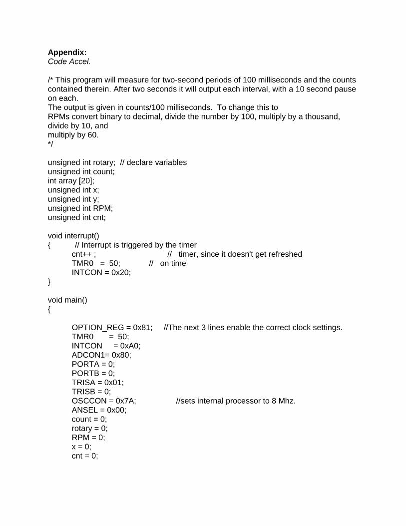
Appendix: Code Accel. /* This program will measure for two-second periods of 100 milliseconds and the counts contained therein. After two seconds it will output each interval, with a 10 second pause on each. The output is given in counts/100 milliseconds. To change this to RPMs convert binary to decimal, divide the number by 100, multiply by a thousand, divide by 10, and multiply by 60. */ unsigned int rotary; // declare variables unsigned int count; int array [20]; unsigned int x; unsigned int y; unsigned int RPM; unsigned int cnt; void interrupt() { // Interrupt is triggered by the timer
cnt++ ; // timer, since it doesn't get refreshed TMR0 = 50; // on time INTCON = 0x20;
} void main() {
OPTION_REG = 0x81; //The next 3 lines enable the correct clock settings. TMR0 = 50; INTCON = 0xA0; ADCON1= 0x80; PORTA = 0; PORTB = 0; TRISA = 0x01; TRISB = 0; OSCCON = 0x7A; //sets internal processor to 8 Mhz. ANSEL = 0x00; count = 0; rotary = 0; RPM = 0; x = 0; cnt = 0;

do {
if (PORTA.F0 == 1)//if (rotary >= 27) {
count = 0; } if (PORTA.F0 == 0) {
count = count+1; } if (count == 2) {
PORTB = ~PORTB; rotary = rotary+1;
} if (cnt == 236) {
PORTA.F2 = ~PORTA.F2; array [x] = rotary; rotary = 0; x++; cnt = 0;
} } while (x < 20); x = 0; INTCON = 0x00; do {
PORTB = array[x]; PORTA.F2 = ~PORTA.F2; delay_ms(10000); x++;
} while (x<20);
}

Code Velocity: /*This program gives you a second by second update of the current velocity of the fan blade (i.e. it reads dark spots), the output is given in counts/100 milliseconds. To change this to RPMs convert binary to decimal, divide the number by 100, multiply by a thousand, divide by 10, and multiply by 60.*/ unsigned int rotary; //declare variables unsigned int count; unsigned int y; unsigned int RPM; unsigned int cnt; void interrupt() { // Interrupt is triggered by the watchdog
cnt++ ; // timer, since it doesn't get refreshed TMR0 = 50; // on time INTCON = 0x20;
} void main() {
OPTION_REG = 0x81; //the first three change clock settings TMR0 = 50; INTCON = 0xA0; ADCON1= 0x80; PORTA = 0; PORTB = 0; TRISA = 0x01; TRISB = 0; OSCCON = 0x7A; //sets internal processor to 8 Mhz. ANSEL = 0x00; //turns off analog to digital converter count = 0; rotary = 0; RPM = 0; cnt = 0; do {
if (PORTA.F0 == 1)//if (rotary >= 27) {

count = 0; } if (PORTA.F0 == 0) {
count = count+1; } if (count == 1) {
rotary = rotary+1; } if (cnt == 236) {
PORTB = rotary; rotary = 0; cnt = 0;
} } while (1);
}
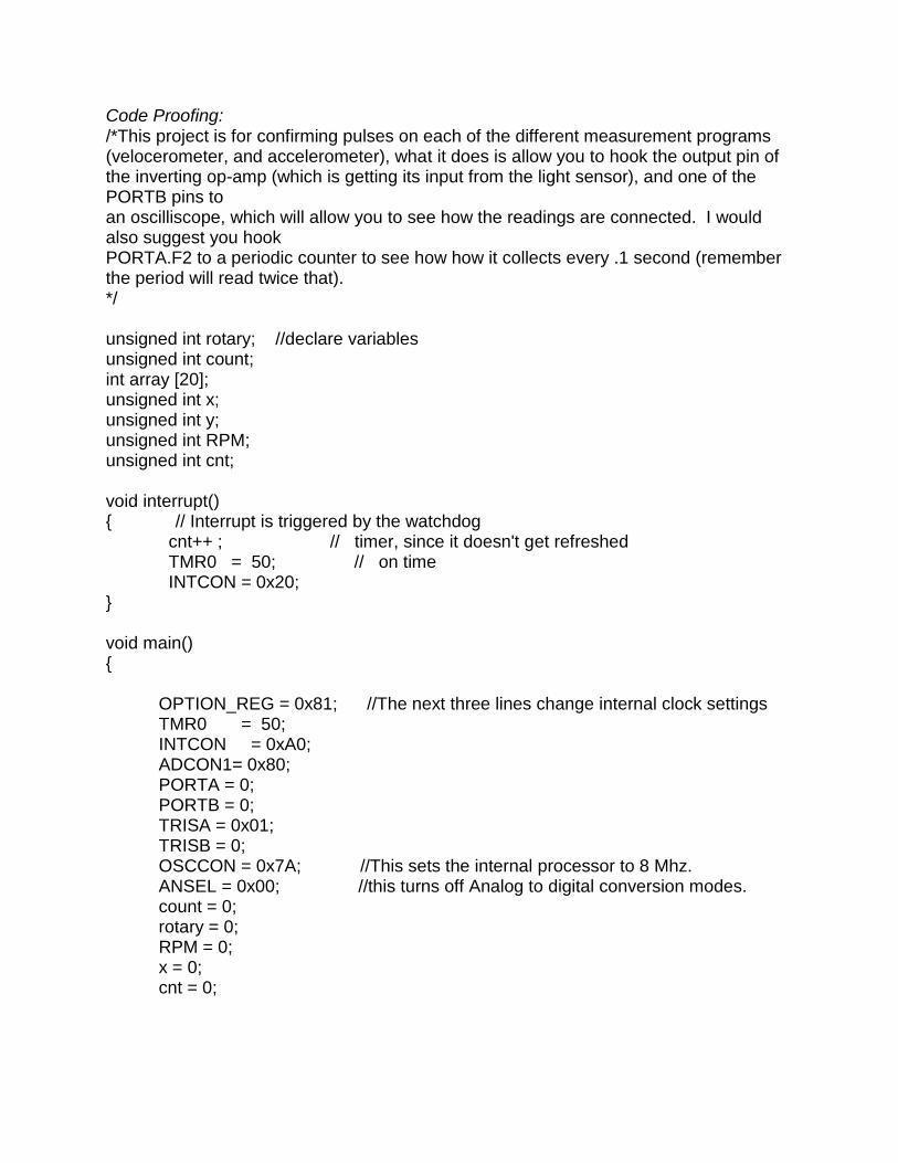
Code Proofing: /*This project is for confirming pulses on each of the different measurement programs (velocerometer, and accelerometer), what it does is allow you to hook the output pin of the inverting op-amp (which is getting its input from the light sensor), and one of the PORTB pins to an oscilliscope, which will allow you to see how the readings are connected. I would also suggest you hook PORTA.F2 to a periodic counter to see how how it collects every .1 second (remember the period will read twice that). */ unsigned int rotary; //declare variables unsigned int count; int array [20]; unsigned int x; unsigned int y; unsigned int RPM; unsigned int cnt; void interrupt() { // Interrupt is triggered by the watchdog
cnt++ ; // timer, since it doesn't get refreshed TMR0 = 50; // on time INTCON = 0x20;
} void main() {
OPTION_REG = 0x81; //The next three lines change internal clock settings TMR0 = 50; INTCON = 0xA0; ADCON1= 0x80; PORTA = 0; PORTB = 0; TRISA = 0x01; TRISB = 0; OSCCON = 0x7A; //This sets the internal processor to 8 Mhz. ANSEL = 0x00; //this turns off Analog to digital conversion modes. count = 0; rotary = 0; RPM = 0; x = 0; cnt = 0;

do {
if (PORTA.F0 == 1) { count = 0;
} if (PORTA.F0 == 0) {
count = count+1; } if (count == 2) {
PORTB = ~PORTB; rotary = rotary+1;
} if (cnt == 236) {
PORTA.F2 = ~PORTA.F2; rotary = 0; cnt = 0;
} } while (1);
}

Code Double Duty: /*CODE double duty The purpose of this code is to provide a program that performs bot the accelerometer and speedometer programs at once the data stored from the first three seconds of reading can be found in the EEprom memory bank, which can be read from the programmer/ */ unsigned int rotary; unsigned int count; int array [40]; unsigned int x; unsigned int y; unsigned int RPM; unsigned int cnt; void interrupt() { // Interrupt is triggered by the watchdog cnt++ ; // timer, since it doesn't get refreshed TMR0 = 50; // on time INTCON = 0x20; } void main() { OPTION_REG = 0x81; TMR0 = 50; INTCON = 0xA0; ADCON1= 0x80; //Turns on interrupts PORTA = 0; PORTB = 0; TRISA = 0x01; TRISB = 0; OSCCON = 0x7A; //Sets clock to eight Megahertz ANSEL = 0x00; //Sets Analog input to zero count = 0; rotary = 0; RPM = 0; x = 0; cnt = 0; do {

if (PORTA.F0 == 1) { count = 0; } if (PORTA.F0 == 0) { count = count+1; } if (count == 1) { \ rotary = rotary+1; } if (cnt == 118) { PORTA.F2 = ~PORTA.F2; PORTB = rotary; array [x] = rotary; rotary = 0; x++; cnt = 0; } } while (x < 40); x = 0; INTCON = 0x00; //turns off interrupts do { EEprom_Write(x, array[x]); //activates EEPROM memory drive and saves

//data in array, in the same manner as the accelerometer PORTA.F2 = ~PORTA.F2; x++; } while (x<40); INTCON = 0xA0; do { if (PORTA.F0 == 1)//if (rotary >= 27) { count = 0; } if (PORTA.F0 == 0) { count = count+1; } if (count == 1) { rotary = rotary+1; } if (cnt == 118) { PORTB = rotary; rotary = 0; cnt = 0; } }

Circuit Schematic: