motor unit mtr-dci - festo.com · 3.6.1 connecting the higher-order controller 3-15..... 3.6.2...
TRANSCRIPT

Description
MTR-DCI-...-DN
Description553531en 1209a[763221]
Motor unitMTR-DCI

Adobe®, Reader®, DeviceNet®, Allen-Bradley®, CANopen®
and CiA® are registered brand names of the respective brandholders in certain countries.

Contents and general safety instructions
IFesto P.BE-MTR-DCI-DN-EN en 1209a
Original de. . . . . . . . . . . . . . . . . . . . . . . . . . . . . . . . . . . . . . .
Edition en 1209a. . . . . . . . . . . . . . . . . . . . . . . . . . . . . . . . . .
Designation P.BE-MTR-DCI-DN-EN. . . . . . . . . . . . . . . . . . . . .
Order no. 553531. . . . . . . . . . . . . . . . . . . . . . . . . . . . . . . . . .
© Festo AG & Co. KG, D-73726 Esslingen, 2012Internet: http://www.festo.comE-mail: [email protected]
Reproduction, distribution or sale of this document orcommunication of its contents to others without expressauthorization is prohibited. Offenders will be liable fordamages. All rights reserved in the event that a patent,utility model or design patent is registered.

Contents and general safety instructions
II Festo P.BE-MTR-DCI-DN-EN en 1209a

Contents and general safety instructions
IIIFesto P.BE-MTR-DCI-DN-EN en 1209a
Contents
Intended use IX. . . . . . . . . . . . . . . . . . . . . . . . . . . . . . . . . . . . . . . . . . . . . . . . . . . . . . . . . .
Safety instructions X. . . . . . . . . . . . . . . . . . . . . . . . . . . . . . . . . . . . . . . . . . . . . . . . . . . . .Target group XI. . . . . . . . . . . . . . . . . . . . . . . . . . . . . . . . . . . . . . . . . . . . . . . . . . . . . . . . . .
Service XI. . . . . . . . . . . . . . . . . . . . . . . . . . . . . . . . . . . . . . . . . . . . . . . . . . . . . . . . . . . . . . .Scope of delivery XI. . . . . . . . . . . . . . . . . . . . . . . . . . . . . . . . . . . . . . . . . . . . . . . . . . . . . . .
Important user instructions XII. . . . . . . . . . . . . . . . . . . . . . . . . . . . . . . . . . . . . . . . . . . . . .
Description of MTR-DCI motor unit XIV. . . . . . . . . . . . . . . . . . . . . . . . . . . . . . . . . . . . . . . . .About the version XV. . . . . . . . . . . . . . . . . . . . . . . . . . . . . . . . . . . . . . . . . . . . . . . . . . . . . .
Product-specific terms and abbreviations XVI. . . . . . . . . . . . . . . . . . . . . . . . . . . . . . . . . . .
1. System overview 1-1. . . . . . . . . . . . . . . . . . . . . . . . . . . . . . . . . . . . . . . . . . . . . . .
1.1 Positioning with electric drives 1-3. . . . . . . . . . . . . . . . . . . . . . . . . . . . . . . . . . . .
1.2 Fieldbus communication 1-6. . . . . . . . . . . . . . . . . . . . . . . . . . . . . . . . . . . . . . . . .
1.2.1 Data exchange using DeviceNet 1-6. . . . . . . . . . . . . . . . . . . . . . . . . . . .
1.2.2 FHPP data profile 1-11. . . . . . . . . . . . . . . . . . . . . . . . . . . . . . . . . . . . . . . .
1.3 Components 1-14. . . . . . . . . . . . . . . . . . . . . . . . . . . . . . . . . . . . . . . . . . . . . . . . . . .
1.4 Control and regulation functions 1-15. . . . . . . . . . . . . . . . . . . . . . . . . . . . . . . . . . .
1.5 Operational safety 1-17. . . . . . . . . . . . . . . . . . . . . . . . . . . . . . . . . . . . . . . . . . . . . .
1.6 Dimensional reference system 1-19. . . . . . . . . . . . . . . . . . . . . . . . . . . . . . . . . . . .
1.6.1 Reference points and positioning range 1-19. . . . . . . . . . . . . . . . . . . . .
1.6.2 Plus/minus signs and directions 1-21. . . . . . . . . . . . . . . . . . . . . . . . . . .
1.6.3 Homing 1-23. . . . . . . . . . . . . . . . . . . . . . . . . . . . . . . . . . . . . . . . . . . . . . . .
2. Mounting 2-1. . . . . . . . . . . . . . . . . . . . . . . . . . . . . . . . . . . . . . . . . . . . . . . . . . . . .
2.1 General instructions 2-3. . . . . . . . . . . . . . . . . . . . . . . . . . . . . . . . . . . . . . . . . . . . .
2.2 Dimensions of the motor unit 2-4. . . . . . . . . . . . . . . . . . . . . . . . . . . . . . . . . . . . .
2.3 Mounting the electric axes 2-5. . . . . . . . . . . . . . . . . . . . . . . . . . . . . . . . . . . . . . . .
3. Installation 3-1. . . . . . . . . . . . . . . . . . . . . . . . . . . . . . . . . . . . . . . . . . . . . . . . . . .
3.1 Overview of installation 3-3. . . . . . . . . . . . . . . . . . . . . . . . . . . . . . . . . . . . . . . . . .
3.2 Earthing 3-6. . . . . . . . . . . . . . . . . . . . . . . . . . . . . . . . . . . . . . . . . . . . . . . . . . . . . . .
3.3 Power supply 3-7. . . . . . . . . . . . . . . . . . . . . . . . . . . . . . . . . . . . . . . . . . . . . . . . . .

Contents and general safety instructions
IV Festo P.BE-MTR-DCI-DN-EN en 1209a
3.3.1 Power supply requirements 3-7. . . . . . . . . . . . . . . . . . . . . . . . . . . . . . .
3.3.2 Load and logic voltage 3-8. . . . . . . . . . . . . . . . . . . . . . . . . . . . . . . . . . .
3.4 Serial interface 3-11. . . . . . . . . . . . . . . . . . . . . . . . . . . . . . . . . . . . . . . . . . . . . . . . .
3.5 Input for external reference switch 3-13. . . . . . . . . . . . . . . . . . . . . . . . . . . . . . . . .
3.6 Field bus 3-15. . . . . . . . . . . . . . . . . . . . . . . . . . . . . . . . . . . . . . . . . . . . . . . . . . . . . .
3.6.1 Connecting the higher-order controller 3-15. . . . . . . . . . . . . . . . . . . . . .
3.6.2 Fieldbus cable 3-17. . . . . . . . . . . . . . . . . . . . . . . . . . . . . . . . . . . . . . . . . .
3.6.3 Fieldbus bit rate and fieldbus length 3-18. . . . . . . . . . . . . . . . . . . . . . . .
4. The control panel (type MTR-DCI-...-H2 only) 4-1. . . . . . . . . . . . . . . . . . . . . . .
4.1 Composition and function of the control panel 4-4. . . . . . . . . . . . . . . . . . . . . . .
4.2 The menu system 4-6. . . . . . . . . . . . . . . . . . . . . . . . . . . . . . . . . . . . . . . . . . . . . . .
4.2.1 Accessing the main menu 4-6. . . . . . . . . . . . . . . . . . . . . . . . . . . . . . . . .
4.2.2 Selecting a menu command 4-6. . . . . . . . . . . . . . . . . . . . . . . . . . . . . . .
4.3 [Diagnostic] menu 4-8. . . . . . . . . . . . . . . . . . . . . . . . . . . . . . . . . . . . . . . . . . . . . .
4.4 [Positioning] menu 4-11. . . . . . . . . . . . . . . . . . . . . . . . . . . . . . . . . . . . . . . . . . . . . .
4.4.1 [Positioning] [Move position set] 4-12. . . . . . . . . . . . . . . . . . . . . . . . . . .
4.4.2 [Positioning] [Demo position table] 4-13. . . . . . . . . . . . . . . . . . . . . . . . .
4.4.3 [Positioning] [Homing] 4-14. . . . . . . . . . . . . . . . . . . . . . . . . . . . . . . . . . . .
4.5 [Settings] menu 4-16. . . . . . . . . . . . . . . . . . . . . . . . . . . . . . . . . . . . . . . . . . . . . . . .
4.5.1 [Settings] [Axis type] 4-17. . . . . . . . . . . . . . . . . . . . . . . . . . . . . . . . . . . . .
4.5.2 [Settings] [Axis parameter] 4-18. . . . . . . . . . . . . . . . . . . . . . . . . . . . . . . .
4.5.3 [Settings] [Homing paramet.] 4-19. . . . . . . . . . . . . . . . . . . . . . . . . . . . . .
4.5.4 [Settings] [Position set] 4-20. . . . . . . . . . . . . . . . . . . . . . . . . . . . . . . . . . .
4.5.5 [Settings] [Password edit] 4-21. . . . . . . . . . . . . . . . . . . . . . . . . . . . . . . . .
4.5.6 [Settings] [BUS parameter] 4-23. . . . . . . . . . . . . . . . . . . . . . . . . . . . . . . .
4.6 Menu command [HMI control] 4-24. . . . . . . . . . . . . . . . . . . . . . . . . . . . . . . . . . . . .
Contents and general safety instructions
VFesto P.BE-MTR-DCI-DN-EN en 1209a
5. Commissioning 5-1. . . . . . . . . . . . . . . . . . . . . . . . . . . . . . . . . . . . . . . . . . . . . . . .
5.1 Commissioning procedure 5-4. . . . . . . . . . . . . . . . . . . . . . . . . . . . . . . . . . . . . . . .
5.2 Commissioning with the control panel (MTR-DCI-...-H2 only) 5-7. . . . . . . . . . . .
5.2.1 Setting the axis type 5-9. . . . . . . . . . . . . . . . . . . . . . . . . . . . . . . . . . . . .
5.2.2 Setting the homing parameters 5-10. . . . . . . . . . . . . . . . . . . . . . . . . . . .
5.2.3 Starting homing 5-13. . . . . . . . . . . . . . . . . . . . . . . . . . . . . . . . . . . . . . . . .
5.2.4 Teaching the axis zero point AZ and the software end positions 5-15. .
5.2.5 Teaching position set records 5-17. . . . . . . . . . . . . . . . . . . . . . . . . . . . . .
5.2.6 Test run 5-18. . . . . . . . . . . . . . . . . . . . . . . . . . . . . . . . . . . . . . . . . . . . . . .
5.2.7 Setting bus parameters 5-20. . . . . . . . . . . . . . . . . . . . . . . . . . . . . . . . . . .
5.3 Commissioning with FCT 5-23. . . . . . . . . . . . . . . . . . . . . . . . . . . . . . . . . . . . . . . . .
5.3.1 Installing the FCT 5-23. . . . . . . . . . . . . . . . . . . . . . . . . . . . . . . . . . . . . . . .
5.3.2 Procedure 5-24. . . . . . . . . . . . . . . . . . . . . . . . . . . . . . . . . . . . . . . . . . . . .
5.3.3 Further information on FCT 5-25. . . . . . . . . . . . . . . . . . . . . . . . . . . . . . . .
5.4 Commissioning a DeviceNet master 5-27. . . . . . . . . . . . . . . . . . . . . . . . . . . . . . . .
5.4.1 Overview of commissioning on the Fieldbus 5-27. . . . . . . . . . . . . . . . . .
5.4.2 Configuration of the DeviceNet master (“I/O configuration”) 5-28. . . .
5.5 Festo profile for handling and positioning (FHPP) 5-30. . . . . . . . . . . . . . . . . . . . .
5.5.1 Supported operating modes 5-30. . . . . . . . . . . . . . . . . . . . . . . . . . . . . . .
5.5.2 Structure of the cyclic I/O data (FHPP standard) 5-32. . . . . . . . . . . . . .
5.5.3 Description of the I/O data (record selection) 5-34. . . . . . . . . . . . . . . . .
5.5.4 Description of the I/O data (direct task) 5-35. . . . . . . . . . . . . . . . . . . . .
5.5.5 Description of the control bytes CCON, CPOS, CDIR 5-36. . . . . . . . . . . .
5.5.6 Description of the status bytes SCON, SPOS, SDIR (RSB) 5-39. . . . . . .
5.5.7 Examples of I/O data 5-42. . . . . . . . . . . . . . . . . . . . . . . . . . . . . . . . . . . . .

Contents and general safety instructions
VI Festo P.BE-MTR-DCI-DN-EN en 1209a
5.6 Sequence control according to the FHPP standard 5-55. . . . . . . . . . . . . . . . . . . .
5.6.1 Homing 5-55. . . . . . . . . . . . . . . . . . . . . . . . . . . . . . . . . . . . . . . . . . . . . . . .
5.6.2 Jog mode 5-57. . . . . . . . . . . . . . . . . . . . . . . . . . . . . . . . . . . . . . . . . . . . . .
5.6.3 Teaching via Fieldbus 5-59. . . . . . . . . . . . . . . . . . . . . . . . . . . . . . . . . . . .
5.6.4 Record selection (Positioning mode) 5-61. . . . . . . . . . . . . . . . . . . . . . . .
5.6.5 Direct task (Positioning mode, Force mode) 5-67. . . . . . . . . . . . . . . . . .
5.6.6 Standstill monitoring 5-74. . . . . . . . . . . . . . . . . . . . . . . . . . . . . . . . . . . . .
5.7 The Festo Parameter Channel (FPC) 5-76. . . . . . . . . . . . . . . . . . . . . . . . . . . . . . . .
5.7.1 Structure of the cyclic I/O data (FHPP-FPC) 5-76. . . . . . . . . . . . . . . . . . .
5.7.2 Request identifiers, response identifiers and error numbers 5-78. . . . .
5.7.3 Rules for request-response processing 5-81. . . . . . . . . . . . . . . . . . . . . .
5.7.4 Parameterisation example 5-83. . . . . . . . . . . . . . . . . . . . . . . . . . . . . . . .
5.8 FHPP finite state machine 5-85. . . . . . . . . . . . . . . . . . . . . . . . . . . . . . . . . . . . . . . .
5.8.1 Establish “ready to operate” status 5-87. . . . . . . . . . . . . . . . . . . . . . . . .
5.8.2 Positioning 5-88. . . . . . . . . . . . . . . . . . . . . . . . . . . . . . . . . . . . . . . . . . . . .
5.9 Notes on operation 5-90. . . . . . . . . . . . . . . . . . . . . . . . . . . . . . . . . . . . . . . . . . . . . .
6. Diagnosis and error display 6-1. . . . . . . . . . . . . . . . . . . . . . . . . . . . . . . . . . . . . .
6.1 Overview of diagnostic options 6-3. . . . . . . . . . . . . . . . . . . . . . . . . . . . . . . . . . . .
6.2 LED status displays 6-5. . . . . . . . . . . . . . . . . . . . . . . . . . . . . . . . . . . . . . . . . . . . .
6.3 Fault messages 6-7. . . . . . . . . . . . . . . . . . . . . . . . . . . . . . . . . . . . . . . . . . . . . . . . .
6.3.1 Overview 6-7. . . . . . . . . . . . . . . . . . . . . . . . . . . . . . . . . . . . . . . . . . . . . .
6.3.2 Description of the messages, warnings, and faults 6-8. . . . . . . . . . . . .
6.4 Diagnosis using Fieldbus 6-12. . . . . . . . . . . . . . . . . . . . . . . . . . . . . . . . . . . . . . . . .
6.4.1 Overview 6-12. . . . . . . . . . . . . . . . . . . . . . . . . . . . . . . . . . . . . . . . . . . . . .
6.4.2 Diagnostic memory 6-13. . . . . . . . . . . . . . . . . . . . . . . . . . . . . . . . . . . . . .
A. Technical appendix A-1. . . . . . . . . . . . . . . . . . . . . . . . . . . . . . . . . . . . . . . . . . . . .
A.1 Technical data A-3. . . . . . . . . . . . . . . . . . . . . . . . . . . . . . . . . . . . . . . . . . . . . . . . . .
A.2 Accessories A-6. . . . . . . . . . . . . . . . . . . . . . . . . . . . . . . . . . . . . . . . . . . . . . . . . . . .
A.3 Motor characteristic curves A-8. . . . . . . . . . . . . . . . . . . . . . . . . . . . . . . . . . . . . . .
A.4 Conversion of units of measurement A-14. . . . . . . . . . . . . . . . . . . . . . . . . . . . . . .

Contents and general safety instructions
VIIFesto P.BE-MTR-DCI-DN-EN en 1209a
B. Reference – Festo DeviceNet and FHPP B-1. . . . . . . . . . . . . . . . . . . . . . . . . . . .
B.1 DeviceNet Reference (Explicit Messaging) B-3. . . . . . . . . . . . . . . . . . . . . . . . . . .
B.1.1 Parameter classes B-3. . . . . . . . . . . . . . . . . . . . . . . . . . . . . . . . . . . . . . .
B.1.2 Object overview (class, attribute, instance) B-4. . . . . . . . . . . . . . . . . . .
B.2 FHPP Reference (I/O messaging) B-10. . . . . . . . . . . . . . . . . . . . . . . . . . . . . . . . . .
B.2.1 Parameter groups B-10. . . . . . . . . . . . . . . . . . . . . . . . . . . . . . . . . . . . . . .
B.2.2 Object overview (Parameter number (PNU) B-11. . . . . . . . . . . . . . . . . .
B.2.3 Layout of the parameter entries B-16. . . . . . . . . . . . . . . . . . . . . . . . . . . .
B.2.4 Device data – Standard parameters B-17. . . . . . . . . . . . . . . . . . . . . . . . .
B.2.5 Device data – Extended parameters B-18. . . . . . . . . . . . . . . . . . . . . . . . .
B.2.6 Diagnosis B-21. . . . . . . . . . . . . . . . . . . . . . . . . . . . . . . . . . . . . . . . . . . . . .
B.2.7 Process data B-25. . . . . . . . . . . . . . . . . . . . . . . . . . . . . . . . . . . . . . . . . . .
B.2.8 Record list B-27. . . . . . . . . . . . . . . . . . . . . . . . . . . . . . . . . . . . . . . . . . . . .
B.2.9 Project data – General B-31. . . . . . . . . . . . . . . . . . . . . . . . . . . . . . . . . . . .
B.2.10 Project data – Force mode B-33. . . . . . . . . . . . . . . . . . . . . . . . . . . . . . . .
B.2.11 Project data – Teaching B-34. . . . . . . . . . . . . . . . . . . . . . . . . . . . . . . . . . .
B.2.12 Project data – Jog mode B-35. . . . . . . . . . . . . . . . . . . . . . . . . . . . . . . . . .
B.2.13 Project data – Direct mode: (Positioning mode) B-36. . . . . . . . . . . . . . .
B.2.14 Project data – Direct mode: (Force mode) B-37. . . . . . . . . . . . . . . . . . . .
B.2.15 Axis parameter, electric drive 1 – Mechanical B-38. . . . . . . . . . . . . . . . .
B.2.16 Axis parameter, electric drives 1 – Homing B-42. . . . . . . . . . . . . . . . . . .
B.2.17 Axis parameter, electric drive 1 – Controller B-44. . . . . . . . . . . . . . . . . .
B.2.18 Axis parameter, electric drive 1 – Electronic Type plate B-49. . . . . . . . .
B.2.19 Axis parameter, electric drive 1 – Standstill monitoring B-51. . . . . . . . .
Contents and general safety instructions
VIII Festo P.BE-MTR-DCI-DN-EN en 1209a
C. The Command Interpreter (CI) C-1. . . . . . . . . . . . . . . . . . . . . . . . . . . . . . . . . . . .
C.1 Data transmission C-3. . . . . . . . . . . . . . . . . . . . . . . . . . . . . . . . . . . . . . . . . . . . . .
C.1.1 Procedure C-3. . . . . . . . . . . . . . . . . . . . . . . . . . . . . . . . . . . . . . . . . . . . .
C.1.2 Structure of the CI commands C-5. . . . . . . . . . . . . . . . . . . . . . . . . . . . .
C.1.3 Checking the data C-9. . . . . . . . . . . . . . . . . . . . . . . . . . . . . . . . . . . . . . .
C.2 CI Reference C-11. . . . . . . . . . . . . . . . . . . . . . . . . . . . . . . . . . . . . . . . . . . . . . . . . . .
C.2.1 Object overview (Index, Subindex) C-11. . . . . . . . . . . . . . . . . . . . . . . . . .
C.2.2 Layout of the parameter entries C-18. . . . . . . . . . . . . . . . . . . . . . . . . . . .
C.2.3 Communication Profile Area (1xxxh) C-19. . . . . . . . . . . . . . . . . . . . . . . .
C.2.4 Manufacturer Specific Profile Area (2xxxh) C-20. . . . . . . . . . . . . . . . . . .
C.2.5 Standardised Device Profile Area (6xxxh) C-26. . . . . . . . . . . . . . . . . . . .
D. Index D-1. . . . . . . . . . . . . . . . . . . . . . . . . . . . . . . . . . . . . . . . . . . . . . . . . . . . . . . . .

Contents and general safety instructions
IXFesto P.BE-MTR-DCI-DN-EN en 1209a
Intended use
The MTR-DCI-... motor unit is an intelligent servo motor con-sisting of DC motor, planetary gear, encoder and inte-grated control electronics (position controller).
The MTR-DCI has been optimised for use with Festo axes (e.g.DMES-... or DNCE-...).
This manual deals with the basic functions of the MTR-DCIand controlling this via the Fieldbus DeviceNet interface.
The Fieldbus interface supports the Festo Fieldbus profile forhandling and positioning (FHPP).
The MTR-DCI and the connectable modules and cables mayonly be used as follows:
– As intended
– In industrial applications
– In perfect technical condition
– In their original state without unauthorised modifications(with the exception of the conversions or modificationsdescribed in the documentation supplied with theproduct).
• Follow the safety instructions and adhere to the intendeduse of each sub-assembly and module as described in thedocumentation.
• Please observe the standards specified in the relevantchapters, the regulations of professional associations, thetechnical monitoring group (TÜV), the VDE regulationsand the relevant national and local regulations.
• Be mindful of the limit values of all additional components(e. g. sensors, actuators).

Contents and general safety instructions
X Festo P.BE-MTR-DCI-DN-EN en 1209a
Safety instructions
When commissioning and programming positioning systems,you must observe the safety regulations in this manual aswell as those in the operating instructions for the other com-ponents used.
The user must make sure that nobody is in the operatingrange of the connected actuators or axis system. Access tothe possible danger area must be prevented by suitablemeasures such as protective screens and warning signs.
WarningElectrical axes can move with high force and at high speed.Collisions can lead to serious injury to human beings anddamage to components.
Make sure that nobody can reach into the operating rangeof the axes or other connected actuators and that noobjects lie in the positioning range while the system is stillconnected to a power supply.
WarningFaults in parameterisation can cause injury to humanbeings and damage to property.
Only enable the controller once the axis system has beeninstalled and parameterised by technically qualified staff.
Contents and general safety instructions
XIFesto P.BE-MTR-DCI-DN-EN en 1209a
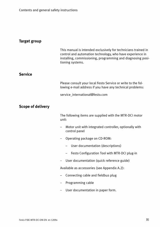
Target group
This manual is intended exclusively for technicians trained incontrol and automation technology, who have experience ininstalling, commissioning, programming and diagnosing posi-tioning systems.
Service
Please consult your local Festo Service or write to the fol-lowing e-mail address if you have any technical problems:
Scope of delivery
The following items are supplied with the MTR-DCI motorunit:
– Motor unit with integrated controller, optionally withcontrol panel
– Operating package on CD-ROM:
– User documentation (descriptions)
– Festo Configuration Tool with MTR-DCI plug-in
– User documentation (quick reference guide)
Available as accessories (see Appendix A.2):
– Connecting cable and fieldbus plug
– Programming cable
– User documentation in paper form.

Contents and general safety instructions
XII Festo P.BE-MTR-DCI-DN-EN en 1209a
Important user instructions
Danger categories
This manual contains instructions on the possible dangerswhich can occur if the product is not used correctly. Theseinstructions are marked (Warning, Caution, etc), printed on ashaded background and marked additionally with apictogram. A distinction is made between the followingdanger warnings:
Warning... means that failure to observe this instruction may resultin serious personal injury or damage to property.
Caution... means that failure to observe this instruction may resultin personal injury or damage to property.
Note... means that failure to observe this instruction may resultin damage to property.
Electrostatically sensitive devices: Incorrect handling canresult in damage to components.
Contents and general safety instructions
XIIIFesto P.BE-MTR-DCI-DN-EN en 1209a
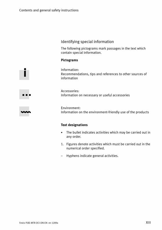
Identifying special information
The following pictograms mark passages in the text whichcontain special information.
Pictograms
Information:Recommendations, tips and references to other sources ofinformation
Accessories:Information on necessary or useful accessories
Environment:Information on the environment-friendly use of the products
Text designations
• The bullet indicates activities which may be carried out inany order.
1. Figures denote activities which must be carried out in thenumerical order specified.
– Hyphens indicate general activities.

Contents and general safety instructions
XIV Festo P.BE-MTR-DCI-DN-EN en 1209a
Description of MTR-DCI motor unit
This description contains information on the mode ofoperation, as well as on assembly, installation andcommissioning of electric valve actuators with motorunit type MTR-DCI-...-DN (DeviceNet interface).
Information´on additional components, e. g. the referenceswitches, can be found in the operating instructions suppliedwith the product in question.
Type Designation Content
Operating package withbrief description anddescriptions (andcommissioning software)on CD-ROM
P.BP-MTR-DCI Brief description: important instructionson commissioning and preliminaryinformationDescriptions on CD-ROM: contents asdescribed below
Description Motor unit of type MTR-DCIwith DeviceNet interfaceP.BE-MTR-DCI-DN-...
Installation, commissioning anddiagnosis of electric drives with MTR-DCImotor unit; communication via theDeviceNet interface.
Help system for software Festo Configuration Toolhelp (contained in FCTsoftware)
Function description of the FestoConfiguration Tool (FCT) configurationsoftware
Operating instructions, ifpresent
Drivese.g. DMES-... / DNCE-...
Fitting and commissioning the drives
Further manuals Motor unit MTR-DCI withother communicationsinterfaces e.g.P.BE-MTR-DCI-IO-...P.BE-MTR-DCI-CO-...P.BE-MTR-DCI-PB-...
Installing, commissioning and diag-nosing electric axes with motor con-troller type MTR-DCI with communica-tion via I/O interface or via the relevantFieldbus.
Table 0/1: Documentation on the MTR-DCI
Contents and general safety instructions
XVFesto P.BE-MTR-DCI-DN-EN en 1209a
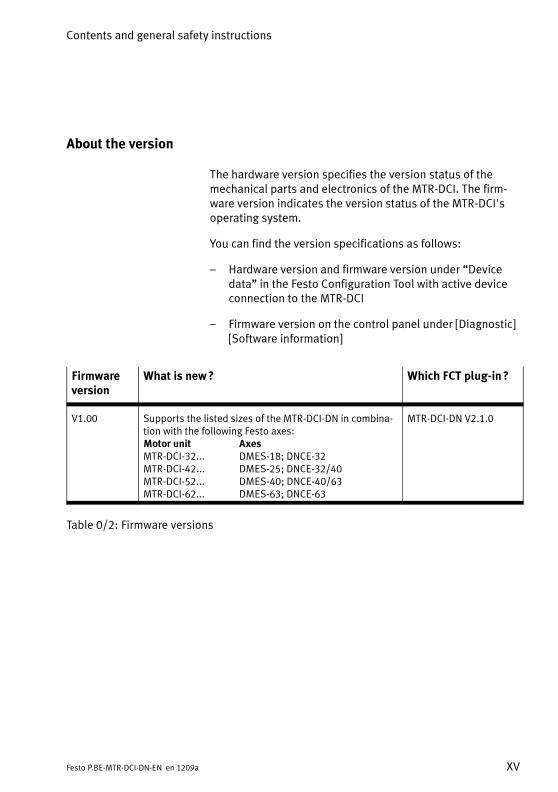
About the version
The hardware version specifies the version status of themechanical parts and electronics of the MTR-DCI. The firm-ware version indicates the version status of the MTR-DCI'soperating system.
You can find the version specifications as follows:
– Hardware version and firmware version under “Devicedata” in the Festo Configuration Tool with active deviceconnection to the MTR-DCI
– Firmware version on the control panel under [Diagnostic][Software information]
Firmwareversion
What is new? Which FCT plug-in?
V1.00 Supports the listed sizes of the MTR-DCI-DN in combina-tion with the following Festo axes:Motor unit AxesMTR-DCI-32... DMES-18; DNCE-32MTR-DCI-42... DMES-25; DNCE-32/40MTR-DCI-52... DMES-40; DNCE-40/63MTR-DCI-62... DMES-63; DNCE-63
MTR-DCI-DN V2.1.0
Table 0/2: Firmware versions
Contents and general safety instructions
XVI Festo P.BE-MTR-DCI-DN-EN en 1209a
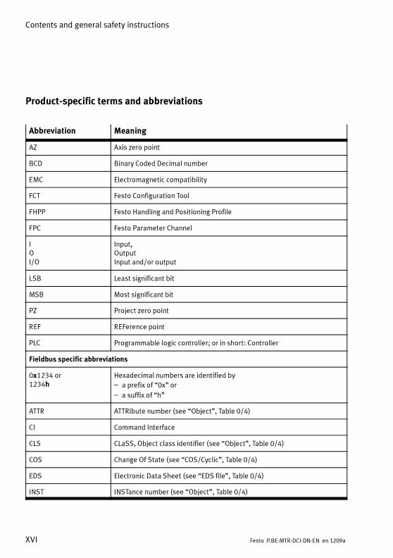
Product-specific terms and abbreviations
Abbreviation Meaning
AZ Axis zero point
BCD Binary Coded Decimal number
EMC Electromagnetic compatibility
FCT Festo Configuration Tool
FHPP Festo Handling and Positioning Profile
FPC Festo Parameter Channel
IOI/O
Input,OutputInput and/or output
LSB Least significant bit
MSB Most significant bit
PZ Project zero point
REF REFerence point
PLC Programmable logic controller; or in short: Controller
Fieldbus specific abbreviations
0x1234 or1234h
Hexadecimal numbers are identified by
– a prefix of “0x” or
– a suffix of “h”
ATTR ATTRibute number (see “Object”, Table 0/4)
CI Command Interface
CLS CLaSS, Object class identifier (see “Object”, Table 0/4)
COS Change Of State (see “COS/Cyclic”, Table 0/4)
EDS Electronic Data Sheet (see “EDS file”, Table 0/4)
INST INSTance number (see “Object”, Table 0/4)

Contents and general safety instructions
XVIIFesto P.BE-MTR-DCI-DN-EN en 1209a
Abbreviation Meaning
MAC-ID Media Access Control IDentifier, see “Participant address”
PNU Parameter number as per FHPP-FPC
Table 0/3: List of abbreviations
Term Meaning
Axis Mechanical component of a drive which converts the motor revolutionsinto positioning movements of a work load. An axis (e.g. positioning servoaxis DMES-...) enables the work load to be mounted and guided and thereference switch to be mounted.
Axis zero point (AZ) Reference point of the software end positions and the project zero posi-tion PZ. The axis zero point AZ is defined by a preset offset to the refer-ence point REF.
Drive Complete actuator, consisting of controller, motor, measuring systemand, if applicable, gear and axis
Operation mode Is used in the following contexts:
– Type of access: Record selection, direct task
– Internal logical state of the controller: Position Profile Mode, ProfileToque Mode, Homing Mode, ...
Controller Contains power electronics + controller + positioning control, analysessensor signals, calculates movements and forces, and provides the motorpower supply via the power electronics.
Encoder Optical pulse generator (rotor position transducer on the motor shaft ofthe MTR-DCI). The electric signals generated are sent to the controller,which then calculates the position and speed on the basis of the signalsreceived.
Festo Configuration Tool(FCT)
Commissioning software with uniform project and data management forall supported device types. The special requirements of a device type aresupported with the necessary descriptions and dialogues by means ofplug-ins.
Festo Handling and Posi-tioning Profile (FHPP)
Uniform field bus data profile for positioning controllers from Festo. Para-meter values, control bytes, and status bytes required during operationcan be directly read and written via the FHPP object directory.
FHPP standard Defines the sequence control as per the “Festo Handling und PositioningProfile”
Contents and general safety instructions
XVIII Festo P.BE-MTR-DCI-DN-EN en 1209a
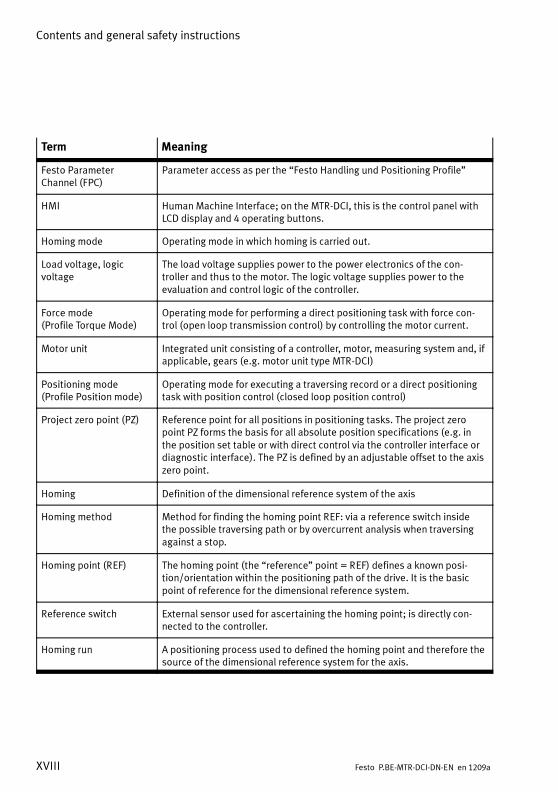
Term Meaning
Festo ParameterChannel (FPC)
Parameter access as per the “Festo Handling und Positioning Profile”
HMI HumanMachine Interface; on the MTR-DCI, this is the control panel withLCD display and 4 operating buttons.
Homing mode Operating mode in which homing is carried out.
Load voltage, logicvoltage
The load voltage supplies power to the power electronics of the con-troller and thus to the motor. The logic voltage supplies power to theevaluation and control logic of the controller.
Force mode(Profile Torque Mode)
Operating mode for performing a direct positioning task with force con-trol (open loop transmission control) by controlling the motor current.
Motor unit Integrated unit consisting of a controller, motor, measuring system and, ifapplicable, gears (e.g. motor unit type MTR-DCI)
Positioning mode(Profile Position mode)
Operating mode for executing a traversing record or a direct positioningtask with position control (closed loop position control)
Project zero point (PZ) Reference point for all positions in positioning tasks. The project zeropoint PZ forms the basis for all absolute position specifications (e.g. inthe position set table or with direct control via the controller interface ordiagnostic interface). The PZ is defined by an adjustable offset to the axiszero point.
Homing Definition of the dimensional reference system of the axis
Homing method Method for finding the homing point REF: via a reference switch insidethe possible traversing path or by overcurrent analysis when traversingagainst a stop.
Homing point (REF) The homing point (the “reference” point = REF) defines a known posi-tion/orientation within the positioning path of the drive. It is the basicpoint of reference for the dimensional reference system.
Reference switch External sensor used for ascertaining the homing point; is directly con-nected to the controller.
Homing run A positioning process used to defined the homing point and therefore thesource of the dimensional reference system for the axis.

Contents and general safety instructions
XIXFesto P.BE-MTR-DCI-DN-EN en 1209a
Term Meaning
Software end position Programmable stroke limitation (point of reference = axis zero point)
– Software end position, positive:
Max. limit position of the stroke in the positive direction; must not beexceeded during positioning.
– Software end position, negative:
Min. limit position in the negative direction; must not be exceededduring positioning.
Teach mode(Teach mode)
Operation mode for setting positions by moving to the target positione. g. when creating position set records.
Jog mode Moving manually in positive or negative direction.
Position set record Positioning command defined in the position set table, consisting of:
– The number of the position set record
– The absolute or relative basis of the target position
– Target position
– Positioning speed
Fieldbus specific terms
Terminating resistor Resistor for minimizing signal reflections. Terminating resistors must beinstalled or switched in at the end of bus segment cables.
Bit Strobe All slaves are queried by a command from themaster. Used for transferring small quantities of data between a masterand one or more slaves, e.g. for synchronisation of input or output data(not supported by MTR-DCI)
COS/Cyclic The messages are sent from the master or slave cyclically (in a fixed timeinterval) or when a state change occurs. With COS messaging, a messageis generated “cyclically” when not status change occurs within a giventimeframe; for this reason, COS and Cyclic are often treated as the samemessage type.
Explicit Messaging Direct connection Explicit Messaging represents an (acyclic) low priority,point-to-point communications connection between two devices and istypically used for configuration and diagnostic purposes. Explicit mess-ages contain the address and value of an attribute and also an identifier(service code) describing how the data is to be handled.
Contents and general safety instructions
XX Festo P.BE-MTR-DCI-DN-EN en 1209a
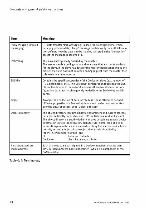
Term Meaning
I/O Messaging (Implicitmessaging)
I/O data transfer “I/O Messaging” is used for exchanging time-criticaldata (e.g. process data). An I/O message contains only data. All informa-tion defining how the data is to be handled is stored in the “Connection”object the message is assigned to.
I/O Polling The slaves are cyclically queried by the master.The master sends a polling command to a slave that also contains datafor the slave. If the slave has data for the master then it sends this to themaster. If a slave does not answer a polling request from the master thenthis leads to a timeout error.
EDS file Contains the specific properties of the DeviceNet slave (e.g. number ofI/Os, parameters, etc.). The DeviceNet configuration tool reads the EDSfiles of the devices in the network and uses these to calculate the con-figuration data that is subsequently loaded into the DeviceNet partici-pants.
Object An object is a collection of data (attributes). These attributes defineddifferent properties of a DeviceNet device and can be read and writtenover the bus. For access, see: “Object directory”
Object directory The object directory contains all device parameters and current processdata that is directly accessible via FHPP, the Fieldbus, or directly via CI.The object directory is subdivided into an area containing general deviceinformation (device identification, manufacturer name, etc.) and com-munication parameters, and an area describing the specific device func-tionality. An entry (object) in the object directory is identified byFHPP FPC: Parameter number PNUCI: Index and SubindexDeviceNet: class, instance, attribute
Participant address(node address)
Each of the up to 64 participants in a DeviceNet network has its ownMAC ID (Media Access Control Identifier); which is a component of theCAN identifier.
Table 0/4: Terminology

System overview
1-1Festo P.BE-MTR-DCI-DN-EN en 1209a
Chapter 1
System overview
1. System overview
1-2 Festo P.BE-MTR-DCI-DN-EN en 1209a
Contents
1. System overview 1-1. . . . . . . . . . . . . . . . . . . . . . . . . . . . . . . . . . . . . . . . . . . . . . .
1.1 Positioning with electric drives 1-3. . . . . . . . . . . . . . . . . . . . . . . . . . . . . . . . . . . .
1.2 Fieldbus communication 1-6. . . . . . . . . . . . . . . . . . . . . . . . . . . . . . . . . . . . . . . . .
1.2.1 Data exchange using DeviceNet 1-6. . . . . . . . . . . . . . . . . . . . . . . . . . . .
1.2.2 FHPP data profile 1-11. . . . . . . . . . . . . . . . . . . . . . . . . . . . . . . . . . . . . . . .
1.3 Components 1-14. . . . . . . . . . . . . . . . . . . . . . . . . . . . . . . . . . . . . . . . . . . . . . . . . . .
1.4 Control and regulation functions 1-15. . . . . . . . . . . . . . . . . . . . . . . . . . . . . . . . . . .
1.5 Operational safety 1-17. . . . . . . . . . . . . . . . . . . . . . . . . . . . . . . . . . . . . . . . . . . . . .
1.6 Dimensional reference system 1-19. . . . . . . . . . . . . . . . . . . . . . . . . . . . . . . . . . . .
1.6.1 Reference points and positioning range 1-19. . . . . . . . . . . . . . . . . . . . .
1.6.2 Plus/minus signs and directions 1-21. . . . . . . . . . . . . . . . . . . . . . . . . . .
1.6.3 Homing 1-23. . . . . . . . . . . . . . . . . . . . . . . . . . . . . . . . . . . . . . . . . . . . . . . .
1. System overview
1-3Festo P.BE-MTR-DCI-DN-EN en 1209a
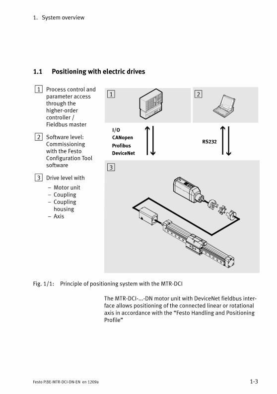
1.1 Positioning with electric drives
1 Process control andparameter accessthrough thehigher-ordercontroller /Fieldbus master
2 Software level:Commissioningwith the FestoConfiguration Toolsoftware
3 Drive level with
– Motor unit– Coupling– Couplinghousing
– Axis
CANopen
I/O
RS232
1 2
3
Profibus
DeviceNet
Fig. 1/1: Principle of positioning system with the MTR-DCI
The MTR-DCI-...-DN motor unit with DeviceNet fieldbus inter-face allows positioning of the connected linear or rotationalaxis in accordance with the “Festo Handling and PositioningProfile”

1. System overview
1-4 Festo P.BE-MTR-DCI-DN-EN en 1209a
You can parameterise and commission the MTR-DCI as fol-lows:
– Using the FCT software package and the RS232 interfaceof your PC.
– With the optional control panel with display and 4 operat-ing buttons (MTR-DCI-...-H2 only).
– Over the Fieldbus.
Functions HMI FCT Field bus
Parameterassignment
– Selecting the axis type and the axis para-meters
– Specifying a gear factor (for externalgears)
– Uploading/downloading configurationdata
– Saving different configurations in projects
x
–
––
x
x
xx
x
x
x–
Position records – Compiling a position set table with setrecord number, target position, posi-tioning mode, positioning speed, acceler-ation
x x x
Commissioning – Homing
– Jog mode
– Teaching positions
– Moving in individual steps
– Starting and stopping positioning pro-cedures while commissioning
– Extended test functions e.g. status dis-plays
– Testing or demonstrating the positionrecords
xxx–x
(x)
x
xxxxx
x
x
xxxxx
x
x
Diagnosis/Service – Reading and displaying diagnostic data x x x

1. System overview
1-5Festo P.BE-MTR-DCI-DN-EN en 1209a
All values are entered and displayed according to the confi-gured units of measurement.
Units of measurement Controlpanel
FCT Field bus
Linear axis Metric Metric units,e. g. mm, mm/s, mm/s2
x x –
Inches 1) Imperial units,e. g. inch, inch/s, inch/s2
– x –
Increments Increment-based measuringunits, e. g. inc, inc/s, inc/s2
– – x
Rotationalaxis
Degrees Angular measurement360° = 1 revolutione. g. deg, deg/s, deg/s2
x x –
Revolutions 2) Number of revolutionse. g. rev, rev/min, rev/min2
x – –
Increments Increment-based measuringunits, e. g. inc, inc/s, inc/s2
– – x
1) Only with FCT when setting up a project.2) Setting only with the control panel [Settings] [Axis type] [Rotation axis]
The setting for the units of measurement influences only thedisplay. In the controller all parameters are always saved inincrement specifications (inc, inc/s, inc/s2 ...) and not con-verted until they are written or read.Measurements transmitted via Fieldbus or RS232 are basedon increments (for conversion see appendix A.4).

1. System overview
1-6 Festo P.BE-MTR-DCI-DN-EN en 1209a
1.2 Fieldbus communication
1.2.1 Data exchange using DeviceNet
DeviceNet was developed by Rockwell Automation and theODVA (Open DeviceNet Vendor Association) as an openFieldbus standard based on the CAN protocol. DeviceNetbelongs to the class of CIP-based networks. CIP (CommonIndustrial Protocol) forms the application layer of DeviceNetand defines the exchange of the following data:
– Explicit messages with low priority, e.g. for configurationor diagnosis.
– I/O messages, e.g. time-critical process data
The Open DeviceNet Vendor Association (ODVA) is the userorganisation for DeviceNet. Publications on the DeviceNet/CIP specifications are provided at
– ODVA (Open DeviceNet Vendor Association)http://www.odva.org
– CI (ControlNet International )http://www.controlnet.org
Explicit Messaging Explicit messages consists of a request and a response. Thisallows services to be requested or executed directly from aparticipant.
Explicit messages contain (target) address, class, instance,attribute, and attribute value, as well as a service code fordata usage.

1. System overview
1-7Festo P.BE-MTR-DCI-DN-EN en 1209a
I/O Messaging I/O messages are sent by a participant and can be receivedand processed by one or more other participants. For I/Omessages, the following dialogues between the participantsare possible:
– The slaves can be cyclically queries by the master(polled I/O) or
– the messages are cyclically sent from the master orslave, or sent when a state change occurs (COS/Cyclic) or
– all slaves are queried by the master with a single com-mand (bit-strobe, not supported by the MTR-DCI).
The data field contains exclusively user data, protocol datais not specified. All information required for using the datais stored in the assigned “Connection Object”.
Up to 64 fieldbus nodes can be operated via the serialCAN bus in a DeviceNet network. The expansion of the net-work depends on the selected bit rate (125 kbps, 250 kbps or500 kbps). DeviceNet telegrams contain up to 8 bytes of userdata. If it is necessary to exchange larger amounts of data,then before sending the data has to be broken down bymeans of fragmentation, transmitted sequentially, and thenput together again in the recipient.
In contrast to other Fieldbus systems, the messages areidentified and not the bus participants. The participants maysend messages when the bus is free. Every bus participantdecides when they want to send data or request other busparticipants to send data. Bus conflicts are resolved byassigning a particular priority (Connection ID) to the mess-ages. The smaller the identifier, the higher the priority. BeforeDeviceNet devices can exchange messages using these IDs,they must first be appropriately configured.

1. System overview
1-8 Festo P.BE-MTR-DCI-DN-EN en 1209a
The configuration data contains the source and targetaddresses of the data for the sender and receiver of themessages.
Object model Access to the data in DeviceNet occurs via objects. EveryDeviceNet participant has one or more objects of differentclasses. An object is an instance of a class:
– Standard classes describe (e.g.) basic properties, com-munications behaviour, or the parameters of individualchannels of a participant.
– Manufacturer-specific classes describe device-specificproperties or parameters.
Device profile Device profiles define the minimum available objects andcommunications functions for each device type. The MTR-DCIconforms to the DeviceNet specification of the device profile“Communication Adapter” (device type number 000Ch).
Predefined connection For simple slave devices, predefined master-slave connec-tions, so-called “Predefined Master/Slave Connection Set”,can be used to simplify the transfer of I/O data between thehigher-level control system (master) and the decentralisedperipherals (slaves). The MTR-DCI-DN operates according tothe specification “Predefined connection set, Group 2 slaveonly”.
1. System overview
1-9Festo P.BE-MTR-DCI-DN-EN en 1209a
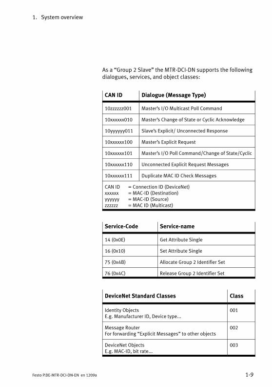
As a “Group 2 Slave” the MTR-DCI-DN supports the followingdialogues, services, and object classes:
CAN ID Dialogue (Message Type)
10zzzzzz001 Master’s I/O Multicast Poll Command
10xxxxxx010 Master’s Change of State or Cyclic Acknowledge
10yyyyyy011 Slave’s Explicit/ Unconnected Response
10xxxxxx100 Master’s Explicit Request
10xxxxxx101 Master’s I/O Poll Command/Change of State/Cyclic
10xxxxxx110 Unconnected Explicit Request Messages
10xxxxxx111 Duplicate MAC ID Check Messages
CAN ID = Connection ID (DeviceNet)xxxxxx = MAC-ID (Destination)yyyyyy = MAC-ID (Source)zzzzzz = MAC ID (Multicast)
Service-Code Service-name
14 (0x0E) Get Attribute Single
16 (0x10) Set Attribute Single
75 (0x4B) Allocate Group 2 Identifier Set
76 (0x4C) Release Group 2 Identifier Set
DeviceNet Standard Classes Class
Identity ObjectsE.g. Manufacturer ID, Device type...
001
Message RouterFor forwarding “Explicit Messages” to other objects
002
DeviceNet ObjectsE.g. MAC-ID, bit rate...
003

1. System overview
1-10 Festo P.BE-MTR-DCI-DN-EN en 1209a
DeviceNet Standard Classes Class
Assembly ObjectsCollection of the attributes of several objects so thatthe data can be sent to or received from severalobjects over a single connection.
004
Connection ObjectsManagement of the resources for “Explicit Messaging”and “I/O-Messaging”.
005
Acknowledge HandlerManagement and responses of receipt acknowledg-ments, acknowledgement timeouts, threshold valuesfor repetition attempts, etc.
043
Festo-specific Classes Class
Diagnostic memory 101
Diagnostic memory (administration) 102
Process data 103
Record list 104
Project data 105
Factor group 106
Axis data electrical drives 1 107
System errors 108
Fieldbus diagnosis 109
1. System overview
1-11Festo P.BE-MTR-DCI-DN-EN en 1209a
1.2.2 FHPP data profile
Festo has developed an optimised data profile, known as the“Festo Handling and Positioning Profile (FHPP)” tailored tohandling and positioning tasks. The FHPP enables uniformcontrol and programming for Festo's various Fieldbus sys-tems and controllers. Parameter values, control bytes, andstatus bytes required during operation can be directly readand written via the object directory.
Communication over the Fieldbus can be selected as cyclic(I/O messaging) or acyclic (Explicit messaging). A mixture ofthese is typical:
– Commissioning and application parameters are trans-ferred using “Explicit messaging”
– Parameter access in normal operation is done as perFHPP FPC (I/O messaging, additional 8 byte I/O) oroptionally using Explicit messaging
– Time-critical process control is done as per the FHPPstandard (“I/O messaging”, 8 byte I/O)
FHPP standard The content and meaning of the cyclical I/O data and thefunctions that can be accessed in the MTR-DCI differdepending on the operating mode.
Direct task:
As a direct task, tasks can be performed in positioning orforce mode. The positioning task is transferred directly in theI/O telegram. The key nominal values (position, speed, force/torque) are transmitted with it. Supplementary parametersare defined via the parameterisation (FHPP FPC or Explicitmessaging).
Record selection
With record positioning, tasks can be carried out in posi-tioning mode. The positioning data are indirectly set usingpositioning records, which are taught via FCT, the controlpanel, or the Fieldbus and then stored in the controller.
1. System overview
1-12 Festo P.BE-MTR-DCI-DN-EN en 1209a
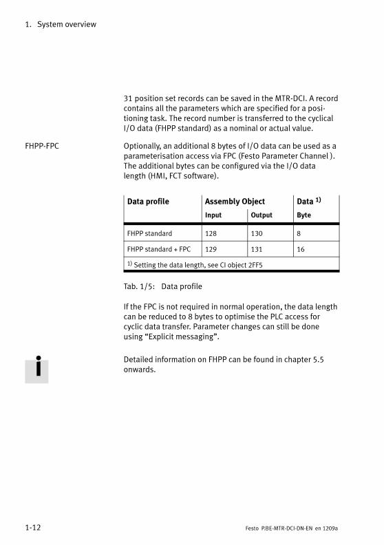
31 position set records can be saved in the MTR-DCI. A recordcontains all the parameters which are specified for a posi-tioning task. The record number is transferred to the cyclicalI/O data (FHPP standard) as a nominal or actual value.
FHPP-FPC Optionally, an additional 8 bytes of I/O data can be used as aparameterisation access via FPC (Festo Parameter Channel ).The additional bytes can be configured via the I/O datalength (HMI, FCT software).
Data profile Assembly Object Data 1)
Input Output Byte
FHPP standard 128 130 8
FHPP standard + FPC 129 131 16
1) Setting the data length, see CI object 2FF5
Tab. 1/5: Data profile
If the FPC is not required in normal operation, the data lengthcan be reduced to 8 bytes to optimise the PLC access forcyclic data transfer. Parameter changes can still be doneusing “Explicit messaging”.
Detailed information on FHPP can be found in chapter 5.5onwards.

1. System overview
1-13Festo P.BE-MTR-DCI-DN-EN en 1209a
Param
...
293 ...
1 ...
...
Direct Task
1
2...
n
Record selection
PNU SI
...DIR.B1/B2
Force modePositioning modePositioning mode
S/C POS
MTR-DCI-...-EDS
100...
1043
(cyclic data channel)I/O messaging
Parameterisation/Service data
( Assembly Instance 129/131)
–...
–
( Assembly Instance 128/130)
16 Byte Tx/Rx
Sequence control/Process data
Explicit messaging(acyclic data channel)
Class
...0x05 0x02
...
Group
...
66
...
...
1
AttrInst
8 Byte Tx/Rx
...CON.B6/B7S/C CON
S/C DIR
8 Byte Tx/Rx
...
... ...
0x09
...
...
...
...
(cyclic data channel)I/O messaging
FHPP standard + FHPP-FPC DeviceNetFHPP standard
Fig. 1/2: Festo Handling and Positioning Profile (FHPP)
1. System overview
1-14 Festo P.BE-MTR-DCI-DN-EN en 1209a
1.3 Components
To construct an electrical drive with the MTR-DCI, you needthe following components:
Motor unit MTR-DCI Motor with controller, available in four sizes, optionally withcontrol panel (type ...-H2).By means of different gear reductions, different require-ments can be fulfilled in respect of (gear) drive outputtorque and (gear) drive output speed (see appendix A.1).Positioning functions are characterised by high torques atlow speeds. With the smaller gear reduction, the positioningspeed of the axis can be increased with correspondinglyreduced force.
Axis Linear or rotational axes as per catalogue
Coupling with couplinghousing
In order to fit Festo axes, e.g. type DMES-... or type DNCE-...,couplings and coupling housings are available as accessor-ies. The motor unit is connected to the axis by means of aclamping connector in the coupling housing. Additional mo-tor flanges are not therefore necessary. Further informationcan be found in the operating instructions for the axis.
Power supply cable Power supply to the MTR-DCI via a power unit. The powerfor the electronics (logic voltage) can also be supplied sep-arately from the load voltage (see section 3.3).
Programming cable For parameterisation of the MTR-DCI during commissioningwith the FCT
Fieldbus cable For connection of the MTR-DCI to any higher-order controller(PLC/IPC).
Reference switch Sensor as described in appendix A.2.
Accessories For positioning systems, Festo provides specially adaptedaccessories (see Festo product range or catalogue).
1. System overview
1-15Festo P.BE-MTR-DCI-DN-EN en 1209a
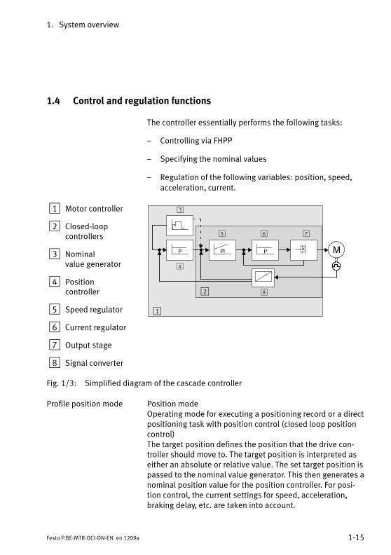
1.4 Control and regulation functions
The controller essentially performs the following tasks:
– Controlling via FHPP
– Specifying the nominal values
– Regulation of the following variables: position, speed,
acceleration, current.
1 Motor controller
2 Closed-loopcontrollers
3 Nominalvalue generator
4 Positioncontroller
5 Speed regulator
6 Current regulator
7 Output stage
8 Signal converter
MP PI
3
8
4
5 6 7
1
2
P
Fig. 1/3: Simplified diagram of the cascade controller
Profile position mode Position modeOperating mode for executing a positioning record or a directpositioning task with position control (closed loop positioncontrol)The target position defines the position that the drive con-troller should move to. The target position is interpreted aseither an absolute or relative value. The set target position ispassed to the nominal value generator. This then generates anominal position value for the position controller. For posi-tion control, the current settings for speed, acceleration,braking delay, etc. are taken into account.

1. System overview
1-16 Festo P.BE-MTR-DCI-DN-EN en 1209a
Changes in position are detected by the internal incrementgenerator (optical encoder). With a known starting point, theactual position is calculated from the gear reduction and/orthe spindle pitch.
Profile torque mode Force modeForce control (open loop transmission control) by controllingthe motor current. This operating mode allows specificationof an external nominal torque value (relative to the nominalmotor current) for the controller. Force control occursindirectly via the control of the motor current. All specifica-tion for forces/torques are defined in relation to the nominalmotor torque or the nominal motor current.
Homing Mode HomingExecution of a positioning task for determining the referencepoint and thus also the origin of the dimensional referencesystem for the axis, e.g. via a reference switch within thepossible motion range or via overcurrent monitoring whenmoving against a stop.
The following additional functions for commissioning, testingor demonstration are available from the control panel of theMTR-DCI-...-H2:
– Positioning travel for defining the target position of a pos-itioning record (Teaching), [Settings] [Position set]
– Positioning run to test all position set records in the posi-tion set table [Demo posit tab].
– Positioning run for testing a certain position set record inthe position set table [Move posit set].

1. System overview
1-17Festo P.BE-MTR-DCI-DN-EN en 1209a
1.5 Operational safety
An extensive system of sensors and monitoring functionsensures operational safety:
– i2t-monitoring
– Temperature monitoring (measuring the motor tempera-ture and the power output stage temperature)
– Current monitoring
– Voltage monitoring
– Detecting faults in the internal voltage supply.
– MTR-DCI-62...: Identification of overvoltage in theintermediate circuit; brake chopper integrated.
– Following error monitoring
– Software end position detection
Please note the following:
• By the arrangement of the limit switches and, if neces-sary, additionally by means of mechanical stops, makesure that the axis always lies within the permitted posi-tioning range.
1. System overview
1-18 Festo P.BE-MTR-DCI-DN-EN en 1209a
WarningFor the purposes of your EMERGENCY STOP procedures,check what measures are necessary for switching yoursystem into a safe state in the event of an EMERGENCYSTOP.
• If an EMERGENCY STOP circuit is required for yourapplication, use additional, separate safety limitswitches (e.g. as normally closed series-connectedswitches)
– for cancelling the ENABLE signal at the control inter-face,
– or for switching off the load voltage.

1. System overview
1-19Festo P.BE-MTR-DCI-DN-EN en 1209a
1.6 Dimensional reference system
For commissioning, a dimensional reference system forhoming the reference coordinates must be defined.The dimensional reference system defines all the (absolute)positions, which can then be approached.
1.6.1 Reference points and positioning range
The dimensional reference system is defined by:
1. Homing for determining the reference point
2. Setting the zero point (Offset between axis zero point andproject zero point)
3. Limiting of the travel range (software end positions)
Homing point REF anchors the dimensional reference system at a referenceswitch or fixed stop, depending on the homing methodchosen. (see also section “Homing”).
Axis zero point AZ is a point at a defined distance from the homing point REF(this distance is the axis zero point offset).
Project zero point PZ is a point of reference within the effective stroke which theuser can select, and to which both the actual position and thetarget positions in the position set table refer.The project zero point is a point at a defined distance fromthe axis zero point AZ (this distance is the project zero pointoffset). The project zero point PZ can only be set via FCT, orby using the CI object 21F4h, or FHPP PNU 500 (not at controlpanel).
Software end point Setting the software end points limits the permissible travelrange (effective stroke). The software end points are relativeto the axis zero point. If a positioning command's target posi-tion lies outside the software end positions, the positioningcommand will not be executed and a fault status will be set.
1. System overview
1-20 Festo P.BE-MTR-DCI-DN-EN en 1209a
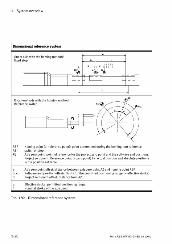
Dimensional reference system
e
f
Linear axis with the homing method:Fixed stop
Rotational axis with the homing method:Reference switch
REFAZPZ
Homing point (or reference point): point determined during the homing run: referenceswitch or stop.Axis zero point: point of reference for the project zero point and the software end positions.Project zero point: Reference point (= zero point) for actual position and absolute positionsin the position set table.
ab, cd
Axis zero point offset: distance between axis zero point AZ and homing point REFSoftware end position offsets: limits for the permitted positioning range (= effective stroke)Project zero point offset: distance from AZ
ef
Effective stroke: permitted positioning rangeNominal stroke of the axis used
Tab. 1/6: Dimensional reference system

1. System overview
1-21Festo P.BE-MTR-DCI-DN-EN en 1209a
Point of reference Calculation rule
Axis zero point AZ = REF + a
Project zero point PZ = AZ + d = (REF + a) + d
Lower software end posi-tion
LSE = AZ + b = (REF + a) + b
Upper software end posi-tion
USE = AZ + c = (REF + a) + c
Tab. 1/7: Calculation regulations for a dimensional reference system with incrementalmeasurement systems
1.6.2 Plus/minus signs and directions
All offsets and position values are vectors (with a given alge-braic sign, + or -). The +/- operating direction of the vectorscan be assigned to the rotation direction of the motor shaft(visual inspection of the motor shaft). The factory settings are“+” for clockwise rotation and “-” for anticlockwise rotation.The active direction can be reversed at the control panel (seechapter 4.5.2) or via FCT. This can be useful when usingangular gear units or toothed belt drives. Homing must becarried out again if the direction is reversed.
The direction in which the work load moves depends on thegearing, the spindle type (left/right-rotating), the algebraicsigns on the positioning specifications (+/-), and the cur-rently set active direction:

1. System overview
1-22 Festo P.BE-MTR-DCI-DN-EN en 1209a
+
—
1
2
+
—
1 Factory setting for active direction
2 Direction change by changing the active direction
Fig. 1/4: Setting the active direction (using the example ofMTR-DCI + DMES, axial gearing, spindle rotating tothe right)

1. System overview
1-23Festo P.BE-MTR-DCI-DN-EN en 1209a
1.6.3 Homing
For drives with incremental measuring systems, homing mustalways be done after switching on. This is defined on adrive.specific basis using the parameter “Homing required”(PNU 1014, CI 23F6h).
The following homing modes are permitted:
– Search for stop in negative direction
– Search for stop in positive direction
– Search for reference switch in positive direction
– Search for reference switch in negative direction(default).
To locate the reference point and position the drive at theaxis zero point, two different speeds can be set.
Homing procedure:
1. Search for the reference point in accordance with theconfigured method
2. Move from the reference point to the axis zero point AZ(axis zero point offset)
3. Set at axis zero point:Current position = 0 – project zero point offset PZ
After a successful homing the drive stops at the axis zeropoint AZ. With first commissioning or when the homingmethod is changed, the offset of the axis zero point = 0; afterhoming the drive then stands at the homing point REF.
1. System overview
1-24 Festo P.BE-MTR-DCI-DN-EN en 1209a
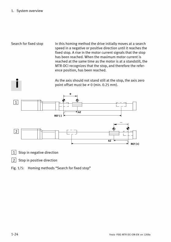
Search for fixed stop In this homing method the drive initially moves at a searchspeed in a negative or positive direction until it reaches thefixed stop. A rise in the motor current signals that the stophas been reached. When the maximum motor current isreached at the same time as the motor is at a standstill, theMTR-DCI recognizes that the stop, and therefore the refer-ence position, has been reached.
As the axis should not stand still at the stop, the axis zeropoint offset must be ≠ 0 (min. 0.25 mm).
+
—
REF (-)
AZ
REF (+)
1
2
AZ
1 Stop in negative direction
2 Stop in positive direction
Fig. 1/5: Homing methods “Search for fixed stop”

1. System overview
1-25Festo P.BE-MTR-DCI-DN-EN en 1209a
Search for reference switch In this homing method the drive initially moves at a searchspeed in a negative or positive direction until it reaches thelimit switch. It then moves back at creep speed: The refer-ence position lies at the point at which the reference switchbecomes inactive again when the drive moves back.
REF (-) AZ
REF (+)
1
2
AZ
+
—
1 Reference switch in negative direction
2 Reference switch in positive direction
Fig. 1/6: Homing methods “Search for reference switch”
If the drive is already at the reference switch when started, itmoves in the opposite direction to the reference switch. Thenthe drive runs as usual to the axis zero point.

1. System overview
1-26 Festo P.BE-MTR-DCI-DN-EN en 1209a

Mounting
2-1Festo P.BE-MTR-DCI-DN-EN en 1209a
Chapter 2
Mounting
2. Mounting
2-2 Festo P.BE-MTR-DCI-DN-EN en 1209a
Contents
2. Mounting 2-1. . . . . . . . . . . . . . . . . . . . . . . . . . . . . . . . . . . . . . . . . . . . . . . . . . . . .
2.1 General instructions 2-3. . . . . . . . . . . . . . . . . . . . . . . . . . . . . . . . . . . . . . . . . . . . .
2.2 Dimensions of the motor unit 2-4. . . . . . . . . . . . . . . . . . . . . . . . . . . . . . . . . . . . .
2.3 Mounting the electric axes 2-5. . . . . . . . . . . . . . . . . . . . . . . . . . . . . . . . . . . . . . . .

2. Mounting
2-3Festo P.BE-MTR-DCI-DN-EN en 1209a
2.1 General instructions
WarningDanger of electric shock, short circuiting or unexpecteddrive motion!
• Always switch off all power supply before carrying outmounting, installation and maintenance work.
NoteHandle all modules and components with great care. Noteespecially the following:
– Screw connections must be fitted free of distortion andmechanical tension. Screws must be fitted accurately(otherwise threads will be damaged).
– The specified torques must be observed.
– The modules must not be offset from one another.
– Contact surfaces must be clean (avoid contact faults).

2. Mounting
2-4 Festo P.BE-MTR-DCI-DN-EN en 1209a
2.2 Dimensions of the motor unit
H0
H2
H1
B1B2
D1D2
D3
D4
L1
L2 L3
L4L55
13
T1
Sizes [mm] 32 42 52 62
Gear reduction G7/G14 G7 G14 G7 G14 G7/G14/G22
Diameter offlange/shaft
D D1D2D3D4
——21.5 h86 h7
42 g1042 ±0.125 h88 h7
52 g1052 ±0.132 h812 h7
62 g1062 ±0.140 j714 h7
Height H H0H1H2
65.3 ±0.421.6 ±0.1541.5 ±0.3
70.8 ±0.426.5 ±0.654.5 ±0.4
94.8 ±0.437 ±0.976.5 ±0.4
128 ±0.560.8 ±0.35128 ±0.5
Length L L1L2L3L4
175.5±1—18.7 ±0.62.5 ±0.3
176 ±133.3 ±125 ±12 ±0.2
176 ±146.3 ±125 ±12 ±0.2
194 ±139 ±133 ±13 ±0.3
194 ±153 ±133 ±13 ±0.3
270 ±147 ±139 ±15 ±0.3
Width B B1B2
33.8 ±0.346.3 ±0.4
44.8 ±0.453.3 ±0.4
63.8 ±0.469.5 ±0.4
105.1 ±0.4105.1 ±0.4
Depth T T1 6 M3: 7 / M4: 10 10 10
Tab. 2/1: Dimensions of the motor unit

2. Mounting
2-5Festo P.BE-MTR-DCI-DN-EN en 1209a
2.3 Mounting the electric axes
When mounting the electric axes, read and keep in mind thedocumentation for the axis used and the additional compo-nents.
WarningIf an axis is mounted in a sloping or vertical position, fal-ling work loads could cause injuries.
• Use the motor unit preferably with self-locking or self-braking spindle drives. This prevents the work loadsliding down suddenly if there is a power failure.
• With DMES-...: check whether additional external safetymeasures against spindle nut fracture are necessary(e. g. toothed latches or moving bolts).
Make sure that:
• The drive is mounted securely and is correctly aligned.
• The working space in which the axis moves is of sufficientsize for operation with a work load.
• The work load does not collide with any component of thedrive when the slide moves into the end position.
• Make sure that you observe the maximum safe values forthe following variables. The point of reference for forcesand torques is the centre of the shaft (L3 see Tab. 2/1).

2. Mounting
2-6 Festo P.BE-MTR-DCI-DN-EN en 1209a
L3
L3 x 0.5
Fy
Fx
Fig. 2/1: Forces and torques
Forces and torques 32 42 52 62
MTR-DCI-...-G7 1-stage
– Radial shaft load– Axial shaft load– Maximum permissible shaft output torque
of the gear unit 1)
Fy [n]Fx [n]Mx [Nm]
40100.4
160500.8
200602.0
240504
MTR-DCI-...-G14/G22 2-stage
– Radial shaft load– Axial shaft load– Maximum permissible shaft output torque
of the gear unit 1)
Fy [n]Fx [n]Mx [Nm]
70201.0
230807.5
32010012.0
3607025 2)
1) With operating factor cb=1.0 (3 hours operation daily, no shocks, direction of rotation constant).The gear output torque or the motor unit is usually much lower, see Technical appendix A,Mechanical data.
2) MTR-DCI-62...-G22: In the start-up phase, torque peaks up to 37 Nm are possible at 20 A peakcurrent.
Tab. 2/2: Safe load for the gear shaft

2. Mounting
2-7Festo P.BE-MTR-DCI-DN-EN en 1209a
NoteMotor unit MTR-DCI-62-...-G22 can generate torque peaksof up to 37 Nm at a peak current of 20 A in the start-upphase.
• Make sure by calculating the dynamic loading thatthe maximum safe shaft output torque for the gear isnot exceeded even in the start-up phase (e.g. byreducing the load).
Use the thread on the front of the gear (see Fig. 2/2) whenmounting the MTR-DCI to a mechanical drive fixture (machineframe).
• In order to minimise the shaft offset: position the axis withthe aid of the centring diameter (D1 or D3, see Tab. 2/1)relative to the rotary axis of the mechanism to be driven.
• Fasten the motor unit with 4 screws and tighten the4 screws with the specified tightening torque.
Motor unit type MTR-DCI-32 has a total of 6 threads fordifferent mounting variants (axial, parallel). In each case only4 screws should be used.
Size Thread/threaddepth
Tightening torque
MTR-DCI-32-... M3 6 mm 1.2 Nm
MTR-DCI-42-... M3 7 mm 1.2 Nm
M4 10 mm 2.9 Nm
MTR-DCI-52-... M5 10 mm 5.9 Nm
MTR-DCI-62-... M5 10 mm 5.9 Nm
Tab. 2/3: Tightening torques

2. Mounting
2-8 Festo P.BE-MTR-DCI-DN-EN en 1209a
To fit Festo axes e. g. type DMES-... or type DGE-..., couplingsand coupling housings are available as accessories. Themotor unit is connected to the axis by means of a clamp in thecoupling housing. Additional motor flanges are not thereforenecessary. Further information can be found in appendix A.2and in the operating instructions for the axis.
25°
25°
50°
M3 x6 (6)
32°
M 4 x10(4x)
M 3 x7 (4x)
4x90° 4
x90°
28°
M 5 x10(4X)
4X90°
45°
M 5 x10(4x)
4x90°
30°
MTR-DCI-32-... MTR-DCI-42-...
MTR-DCI-52-... MTR-DCI-62-...
Ø 32
Ø32
Ø36
Ø40
Ø50
Fig. 2/2: Mounting the drive by means of front threads (direct fastening)

Installation
3-1Festo P.BE-MTR-DCI-DN-EN en 1209a
Chapter 3
Installation
3. Installation
3-2 Festo P.BE-MTR-DCI-DN-EN en 1209a
Contents
3. Installation 3-1. . . . . . . . . . . . . . . . . . . . . . . . . . . . . . . . . . . . . . . . . . . . . . . . . . .
3.1 Overview of installation 3-3. . . . . . . . . . . . . . . . . . . . . . . . . . . . . . . . . . . . . . . . . .
3.2 Earthing 3-6. . . . . . . . . . . . . . . . . . . . . . . . . . . . . . . . . . . . . . . . . . . . . . . . . . . . . . .
3.3 Power supply 3-7. . . . . . . . . . . . . . . . . . . . . . . . . . . . . . . . . . . . . . . . . . . . . . . . . .
3.3.1 Power supply requirements 3-7. . . . . . . . . . . . . . . . . . . . . . . . . . . . . . .
3.3.2 Load and logic voltage 3-8. . . . . . . . . . . . . . . . . . . . . . . . . . . . . . . . . . .
3.4 Serial interface 3-11. . . . . . . . . . . . . . . . . . . . . . . . . . . . . . . . . . . . . . . . . . . . . . . . .
3.5 Input for external reference switch 3-13. . . . . . . . . . . . . . . . . . . . . . . . . . . . . . . . .
3.6 Field bus 3-15. . . . . . . . . . . . . . . . . . . . . . . . . . . . . . . . . . . . . . . . . . . . . . . . . . . . . .
3.6.1 Connecting the higher-order controller 3-15. . . . . . . . . . . . . . . . . . . . . .
3.6.2 Fieldbus cable 3-17. . . . . . . . . . . . . . . . . . . . . . . . . . . . . . . . . . . . . . . . . .
3.6.3 Fieldbus bit rate and fieldbus length 3-18. . . . . . . . . . . . . . . . . . . . . . . .
3. Installation
3-3Festo P.BE-MTR-DCI-DN-EN en 1209a
3.1 Overview of installation
WarningDanger of electric shock, short circuiting or unexpecteddrive motion!
• Always switch off all power supply before carrying outmounting, installation and maintenance work.
CautionFaulty pre-assembled lines may destroy the electronicsand trigger unexpected movements of the motor.
• When connecting the electric components of the systemuse the cables that are listed as accessories (seeTab. 3/2). This is the only way to ensure the system willwork properly.
Note• Lay all moveable motor and sensor cables free of bendsand free of mechanical stress, in a drag chain ifnecessary.

3. Installation
3-4 Festo P.BE-MTR-DCI-DN-EN en 1209a
1 Serialinterface
2 ConnectionReference switch
3 Fieldbus interface(I/F)
4 Powersupply (Power)
1
2
3
4
Fig. 3/1: Connections on the MTR-DCI
Connection on the MTR-DCI Description
1 Serial interface – M8x1, 4-pin
– socket
RS232 interface for parameterising, commis-sioning and diagnosing with FCT
2 Reference switch – M8x1, 3-pin
– socket
Sensor input for N.O. (normally open) switch typein PNP configuration
3 Fieldbus interface – Sub-D, 9-pin
– Plug
Interface for connecting the higher-level controlsystem via Fieldbus (DeviceNet)
4 Power supply – Sub-D, 2-pin
– Plug
Connection with two high-current contacts
Tab. 3/1: Description of the connections
If non-assigned plug connectors are touched, there is adanger that damage may occur to the MTR-DCI or to otherparts of the system as a result of ESD (electrostatic dis-charge). Place protective caps on unused terminals in orderto prevent such discharges.

3. Installation
3-5Festo P.BE-MTR-DCI-DN-EN en 1209a
The plug connectors of the following Festo cables have beendesigned so that, when inserted and screwed tight, or if fittedwith protective covers, the connections on the MTR-DCI willcomply with protection class IP54.
CautionLong lines reduce immunity to interference (EMC).
• Do not exceed the specified maximum cable lengths.
Connection Cable Designation Length [m]
Serial interface Programming cable KDI-MC-M8-SUB-9-2,5 2.5 (max. 2.5)
Homing Switch Connecting cable KM8-M8-GSGD-... 0.5 / 1 / 2 / 5
Fieldbus interface Field bus plug for M12adapter
FBA-CO-SUB-9-M12 –
Voltage supply Power supply cable KPWR-MC-1-SUB-9HC-... 2.5 / 5 / 10(max. 10)
Tab. 3/2: Overview of cables (accessories)
To maintain the IP protection class:
• Seal unused M8 connections with ISK-M8 protective caps(accessories).
• Hand-tighten the union nuts/locking screws of the plugs:
Observe the permitted tightening torques specified in thedocumentation for the cables and connectors used.

3. Installation
3-6 Festo P.BE-MTR-DCI-DN-EN en 1209a
3.2 Earthing
Note• Connect the earth terminal of the MTR-DCI with low im-pedance (short cable with large cross section) to theearth potential.
This prevents interference from electromagnetic sourcesand ensures electromagnetic compatibility in accordancewith EMC directives.
To connect the MTR-DCI to the earth potential use only thefollowing earthing connection:
– Earthing strap at the free end of the power supply cable;see assembly instructions for cable typeKPWR-MC-1-SUB-9HC-... (see chapter 3.3.2)
CautionEarth or mass loops can make EMC safety measures inef-fective and allow high compensating currents to destroythe motor unit.
• Connect only the cable screen of the power supply cableto the functional earth FE.
• Do not connect the GND connection to the housing,screening or functional earth FE!
• Never connect one of the power supply connections (seechapter 3.2, A1, A2) to the FE or the housing.
This will avoid damaging the device and impairing protec-tion against electromagnetic interference (EMC).

3. Installation
3-7Festo P.BE-MTR-DCI-DN-EN en 1209a
3.3 Power supply
3.3.1 Power supply requirements
Warning• In order to provide the electric power supply, use onlyPELV circuits as per IEC/DIN EN 60204-1 (ProtectiveExtra-Low Voltage, PELV).Take into account also the general requirements forPELV circuits as per IEC/DIN EN 60204-1.
• Use only power sources providing reliable electricalisolation of the operating voltage as per IEC/DINEN 60204-1.
By the use of PELV power units, protection against electricshock (protection against direct and indirect contact) is guar-anteed in accordance with IEC/DIN EN 60204-1 (electricalequipment of machines, general requirements).
CautionDevice damage from overvoltage
The voltage inputs of the motor unit have no internalprotection against overvoltage.
• Make sure that the permitted voltage tolerance is notexceeded. The tolerance must also be observed directlyat the operating voltage connections on the MTR-DCI(see appendix A.1).
• Install external fuses (see Tab. 3/4).
3. Installation
3-8 Festo P.BE-MTR-DCI-DN-EN en 1209a
3.3.2 Load and logic voltage
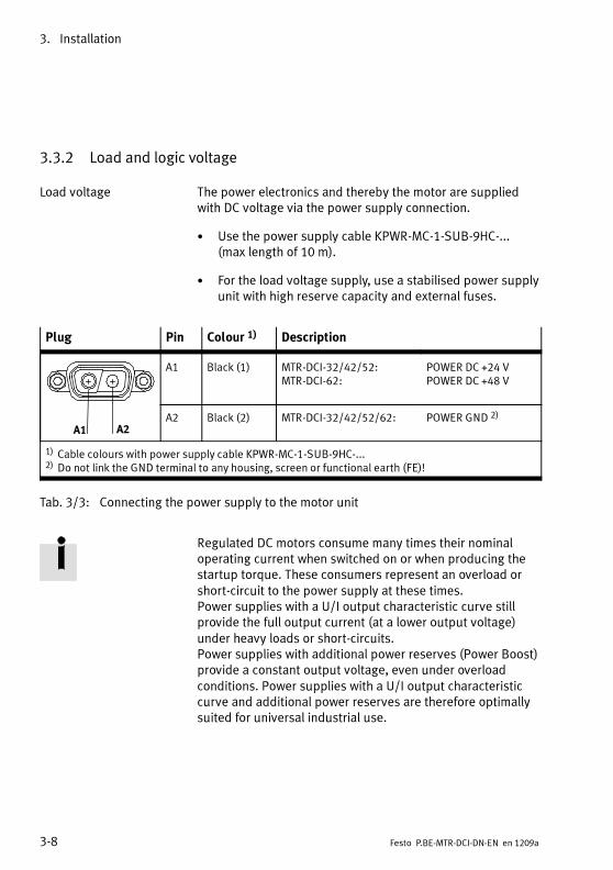
Load voltage The power electronics and thereby the motor are suppliedwith DC voltage via the power supply connection.
• Use the power supply cable KPWR-MC-1-SUB-9HC-...(max length of 10 m).
• For the load voltage supply, use a stabilised power supplyunit with high reserve capacity and external fuses.
Plug Pin Colour 1) Description
A1 A2
A1 Black (1) MTR-DCI-32/42/52:MTR-DCI-62:
POWER DC +24 VPOWER DC +48 V
A2 Black (2) MTR-DCI-32/42/52/62: POWER GND 2)
1) Cable colours with power supply cable KPWR-MC-1-SUB-9HC-...2) Do not link the GND terminal to any housing, screen or functional earth (FE)!
Tab. 3/3: Connecting the power supply to the motor unit
Regulated DC motors consume many times their nominaloperating current when switched on or when producing thestartup torque. These consumers represent an overload orshort-circuit to the power supply at these times.Power supplies with a U/I output characteristic curve stillprovide the full output current (at a lower output voltage)under heavy loads or short-circuits.Power supplies with additional power reserves (Power Boost)provide a constant output voltage, even under overloadconditions. Power supplies with a U/I output characteristiccurve and additional power reserves are therefore optimallysuited for universal industrial use.

3. Installation
3-9Festo P.BE-MTR-DCI-DN-EN en 1209a
Note the following selection criteria for the MTR-DCI powersupply:
– The power supply nominal current should be at least thesame as the motor startup current (peak current).
– The motor tolerances should be allowed for with 20% -50% reserve power.
voltage supply MTR-…-32 MTR-…-42 MTR-…-52 MTR-…-62
Motor nominal current A 0.73 2 5 6.19
Motor peak current A 2.1 3.8 7.7 20
Nominal current of power sup-ply unit
A ≥ 3 ≥ 6 ≥ 10 ≥ 15 1)
External fusesecondary side
A 5 Aslow-blowing
7 Aslow-blowing
10 Aslow-blowing
25 Aslow-blowing
1) Exception
Tab. 3/4: Power supply and fuse requirements
1 external fuse
2 Earthingconnection (seechapter 3.2)
A1 A2
A1 A2
Fig. 3/2: Connection example – Power supply

3. Installation
3-10 Festo P.BE-MTR-DCI-DN-EN en 1209a
Logic voltage In operation, the logic voltage is connected via the FBA-...Fieldbus adapter separately to the load voltage.
For MTR-DCI-42, 52, 62: For commissioning purposes, thelogic voltage can be optionally connected together with theload voltage via the power supply connection. In normal oper-ation, the logic voltagemust be connected separately to theload voltage via the FBA-... Fieldbus adapter.
With separate supply, the load voltage can be switched offe.g. in the case of EMERGENCY-STOP, with logic voltage con-tinuing to be applied and the controller remaining functionaland retaining its reference position.
Switch-on sequence Do not switch on the logic voltage after the load voltage,since this may cause the MTR-DCI to switch off and back onagain (= reset).
Logic voltage failure If the logic voltage fails, the controller will switch off.For MTR-DCI-42, 52, 62: if the load voltage is still active, thecontroller will switch back on but will lose its reference posi-tion.
Logic voltage supply 32 42 52 62
– In operation:via Fieldbus adapter FBA-...
x x x x
– For commissioning and para-meterisation:optionally via the power supplyconnection
— x x x
Tab. 3/5: Logic voltage supply
Information on the connection specifications of the Fieldbusadapter is provided in chapter 3.6.1 and also in the installa-tion manual of the Fieldbus adapter.

3. Installation
3-11Festo P.BE-MTR-DCI-DN-EN en 1209a
3.4 Serial interface
Serial interface for parameter assignment, commissioningand diagnosis
Use the following cable exclusively for connecting a PC to theMTR-DCI:– Programming cable KDI-MC-M8-SUB-9-2.5
• If necessary, remove the protective cap from the serialinterface of the MTR-DCI.
• Connect the following terminals with the programmingcable:
– The connection socket on the MTR-DCI.
– A serial interface COMx on the diagnostic PC.
M8x1 socket Description
1 2 4 3
1 GND Ground
2 TXD RS232 transmitting cable 1)
3 RXD RS232 receiving cable 1)
4 --- Reserved for service personnel –do not connect!
1) The levels conform to the RS232 standardData transfer rate: 9600 bit/s
Tab. 3/6: Pin allocation for the serial interface on theMTR-DCI
3. Installation
3-12 Festo P.BE-MTR-DCI-DN-EN en 1209a
Information on commissioning and parameterising theMTR-DCI via the serial interface can be found in chapter 5.3and in the help system for the FCT software package.Information on transmitting CI commands via the serialinterface can be found in appendix C.1.2.
NoteThe RS232 communications port is not electrically isolated.It is not suitable for permanent connection to PC systems,nor for use as a control interface.
• Use this terminal only for commissioning.
• Remove the programming cable in continuous opera-tion.
• Seal the connection with the protective cap supplied(ISK-M8).

3. Installation
3-13Festo P.BE-MTR-DCI-DN-EN en 1209a
3.5 Input for external reference switch
If you are not using a reference switch:
• Seal the connection with the protective cap supplied(ISK-M8).
When selecting the reference switch:
• For the reference switch, use the correct “N.O.”(normally-open) switch type in PNP configuration.
• Use a reference switch with a screw-type lock (externalthread M8x1) at the end of the cable, or use the connect-ing cable KM8-M8-... with a screw-type lock as an ad-apter.
Use (e.g.) the following Festo proximity sensors:
– magnetic proximity sensor SMT-8M-...
– inductive proximity sensor SIEN-...-M8B-...
• When selecting the sensor, note that the accuracy of theswitchover point of the sensor determines the accuracy ofthe homing (reference) point.
M8x1 socket Description
1 34
1 DC +24 V DC + 24 V voltage output(only for reference switch)
4 REF Reference switch contact
3 GND Ground
Tab. 3/7: REF connection (reference switch) on the MTR-DCI
The power supply for the reference switch (DC 24 V/Ground)is provided via pin 1/3.
3. Installation
3-14 Festo P.BE-MTR-DCI-DN-EN en 1209a
CautionDamage to the device
The DC 24 V voltage on pin 1 does not have any specialprotection against overload; the voltage is taken from themain supply with protection against ESD and incorrectpolarity.
• Use the terminal only for the reference switch (sensorsupply).
Use of this connection as a power supply for other devicesis not safe.
The input for REF sensor signal complies in its electricalproperties with the input specifications in the appendix“Technical data”.
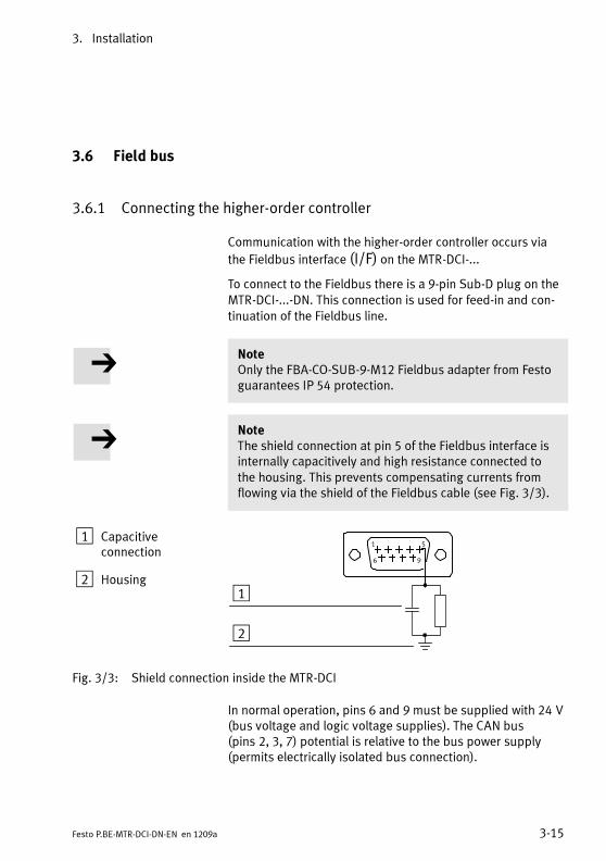
3. Installation
3-15Festo P.BE-MTR-DCI-DN-EN en 1209a
3.6 Field bus
3.6.1 Connecting the higher-order controller
Communication with the higher-order controller occurs via
the Fieldbus interface (I/F) on the MTR-DCI-...
To connect to the Fieldbus there is a 9-pin Sub-D plug on theMTR-DCI-...-DN. This connection is used for feed-in and con-tinuation of the Fieldbus line.
NoteOnly the FBA-CO-SUB-9-M12 Fieldbus adapter from Festoguarantees IP 54 protection.
NoteThe shield connection at pin 5 of the Fieldbus interface isinternally capacitively and high resistance connected tothe housing. This prevents compensating currents fromflowing via the shield of the Fieldbus cable (see Fig. 3/3).
1 Capacitiveconnection
2 Housing
51
96
1
2
Fig. 3/3: Shield connection inside the MTR-DCI
In normal operation, pins 6 and 9 must be supplied with 24 V(bus voltage and logic voltage supplies). The CAN bus(pins 2, 3, 7) potential is relative to the bus power supply(permits electrically isolated bus connection).
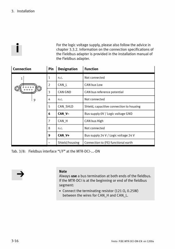
3. Installation
3-16 Festo P.BE-MTR-DCI-DN-EN en 1209a
For the logic voltage supply, please also follow the advice inchapter 3.3.2. Information on the connection specifications ofthe Fieldbus adapter is provided in the installation manual ofthe Fieldbus adapter.
Connection Pin Designation Function
1
9
1 n.c. Not connected
2 CAN_L CAN bus Low
3 CAN GND CAN bus reference potential
4 n.c. Not connected
5 CAN_SHLD Shield, capacitive connection to housing
6 CAN_V– Bus supply 0V / Logic voltage GND
7 CAN_H CAN bus High
8 n.c. Not connected
9 CAN_V+ Bus supply 24 V / Logic voltage 24 V
– Shield/housing Connection to (FE) functional earth
Tab. 3/8: Fieldbus interface “I/F” at the MTR-DCI-...-DN
NoteAlways use a bus termination at both ends of the fieldbus.If the MTR-DCI is at the beginning or end of the fieldbussegment:
• Connect the terminating resistor (121 Ω, 0.25W)between the wires for CAN_H and CAN_L.

3. Installation
3-17Festo P.BE-MTR-DCI-DN-EN en 1209a
3.6.2 Fieldbus cable
NoteFaulty installation and high transmission rates may causedata transmission errors as a result of signal reflectionsand attenuations.Transmission errors can be caused by:
– missing or incorrect terminating resistor
– incorrect screened connection
– branches
– transmission over long distances
– inappropriate cables
Observe the cable specifications! For information on thecable type refer to the manual for your controller or to theDeviceNet specification.
NoteIf the MTR-DCI is mounted onto a moving part of amachine, the Fieldbus cable on the moving part must beprovided with strain relief. Please observe also the relevantregulations in EN 60204 part 1.
Use a shielded, twisted pair 4-wire cable as a fieldbus cable.When using a Festo fieldbus a cable diameter of 5 ... 8 or7 ... 10 mm is permitted.
Bus length Exact specifications on the bus length can be found in thenext section and in the manuals for your control system.

3. Installation
3-18 Festo P.BE-MTR-DCI-DN-EN en 1209a
3.6.3 Fieldbus bit rate and fieldbus length
NoteThe maximum permitted length for fieldbus segments de-pends on the bit rate used. You will find detailed informa-tion in the manuals for your control system or bus inter-face or DeviceNet specification.
• Note the maximum permitted segment length (cablelength without repeater) if you are connecting the MTR-DCI to a fieldbus segment.
• Avoid branch lines.
Note• Refer to the manuals for your control system or bus in-terface in order to ascertain which T-adapter and maxim-um branch line length are permitted for your controller.
• Also take into account the sum of the branch line lengthswhen calculating the maximum permitted length of thefieldbus cable.
Bit rate Maximum segment length
500 kbps 100 m
250 kBit/s 250 m
125 kBit/s 500 m
Tab. 3/9: Maximum length of fieldbus segments as a func-tion of the bit rate
Information on setting the bit rate and further bus paramet-ers on the control panel can be found in section 5.2.7.
The control panel (type MTR-DCI-...-H2 only)
4-1Festo P.BE-MTR-DCI-DN-EN en 1209a
Chapter 4
The control panel (type MTR-DCI-...-H2 only)

4. The control panel (type MTR-DCI-...-H2 only)
4-2 Festo P.BE-MTR-DCI-DN-EN en 1209a
Contents
4. The control panel (type MTR-DCI-...-H2 only) 4-1. . . . . . . . . . . . . . . . . . . . . . .
4.1 Composition and function of the control panel 4-4. . . . . . . . . . . . . . . . . . . . . . .
4.2 The menu system 4-6. . . . . . . . . . . . . . . . . . . . . . . . . . . . . . . . . . . . . . . . . . . . . . .
4.2.1 Accessing the main menu 4-6. . . . . . . . . . . . . . . . . . . . . . . . . . . . . . . . .
4.2.2 Selecting a menu command 4-6. . . . . . . . . . . . . . . . . . . . . . . . . . . . . . .
4.3 [Diagnostic] menu 4-8. . . . . . . . . . . . . . . . . . . . . . . . . . . . . . . . . . . . . . . . . . . . . .
4.4 [Positioning] menu 4-11. . . . . . . . . . . . . . . . . . . . . . . . . . . . . . . . . . . . . . . . . . . . . .
4.4.1 [Positioning] [Move position set] 4-12. . . . . . . . . . . . . . . . . . . . . . . . . . .
4.4.2 [Positioning] [Demo position table] 4-13. . . . . . . . . . . . . . . . . . . . . . . . .
4.4.3 [Positioning] [Homing] 4-14. . . . . . . . . . . . . . . . . . . . . . . . . . . . . . . . . . . .
4.5 [Settings] menu 4-16. . . . . . . . . . . . . . . . . . . . . . . . . . . . . . . . . . . . . . . . . . . . . . . .
4.5.1 [Settings] [Axis type] 4-17. . . . . . . . . . . . . . . . . . . . . . . . . . . . . . . . . . . . .
4.5.2 [Settings] [Axis parameter] 4-18. . . . . . . . . . . . . . . . . . . . . . . . . . . . . . . .
4.5.3 [Settings] [Homing paramet.] 4-19. . . . . . . . . . . . . . . . . . . . . . . . . . . . . .
4.5.4 [Settings] [Position set] 4-20. . . . . . . . . . . . . . . . . . . . . . . . . . . . . . . . . . .
4.5.5 [Settings] [Password edit] 4-21. . . . . . . . . . . . . . . . . . . . . . . . . . . . . . . . .
4.5.6 [Settings] [BUS parameter] 4-23. . . . . . . . . . . . . . . . . . . . . . . . . . . . . . . .
4.6 Menu command [HMI control] 4-24. . . . . . . . . . . . . . . . . . . . . . . . . . . . . . . . . . . . .

4. The control panel (type MTR-DCI-...-H2 only)
4-3Festo P.BE-MTR-DCI-DN-EN en 1209a
The control panel of motor unit MTR-DCI-...-H2 enables com-missioning directly on the MTR-DCI. An overview of the keyand menu functions can be found in this chapter.Commissioning with the control panel is described fromchapter 5.2 .
With the MTR-DCI-...-R2 (without control panel) you can com-mission the MTR-DCI via the RS232 interface (with FCT soft-ware). Instructions on this can be found in chapter 5.3.
CautionSimultaneous access of control functions and operatingfunctions by the FCT and the control panel can causefaults.
• Make sure that FCT and the control panel are not in useat the same time.
• If necessary, utilise the facility to disable parameterisa-tion and positioning functions from the control panel(HMI Access, see section 5.5.2).
NoteRemove the protective film from the display, if still fitted,before using it for the first time.

4. The control panel (type MTR-DCI-...-H2 only)
4-4 Festo P.BE-MTR-DCI-DN-EN en 1209a
4.1 Composition and function of the control panel
1 LC display
2 Operatingbuttons
3 LEDs– Power (green)– I/F (green/red)– Error (red)
1 32
Fig. 4/1: Control panel of the MTR-DCI-...-H2-...
LC display The graphical LCD (128 x 64 pixels) shows all text in English.The display can be rotated if required; see the menucommands [LCD adjustment].
Membrane keyboard The 4 buttons on the membrane keyboard are used toperform menu-driven settings and commissioning functions:
– Parameter assignment and referencing the axis
– Teaching of standard applications and editing of posi-tioning sets
– Execution/Testing of individual positioning sets.
LEDs The operating statuses are indicated visually by 3 LEDs(see also chapter 6.2):
– Power: Power supply
– I/F: Bus status (Network, Module)
– Error: Faults

4. The control panel (type MTR-DCI-...-H2 only)
4-5Festo P.BE-MTR-DCI-DN-EN en 1209a
Function Button
MENU Activates the main menu from the status display.Menu
ESC Rejects the current entry and switches back in stages to the higher menulevel or status display.
EMERG.STOP Interrupts the current positioning procedure (> Error mode; confirmwith <Enter>, then automatic return to the status display). Only when HMI= on!
OK Confirms the current selection or entry.Enter
SAVE Saves parameter settings permanently in the EEPROM.
START/STOP Starts or stops a positioning procedure (only in Demo mode).After stop: display of current position; use <Menu> to return to thehigher menu level.
<- -> Scrolls within a menu level in order to select a menu command.v
VEDIT Sets parameters.
Tab. 4/1: Button function (overview)

4. The control panel (type MTR-DCI-...-H2 only)
4-6 Festo P.BE-MTR-DCI-DN-EN en 1209a
4.2 The menu system
4.2.1 Accessing the main menu
When the power supply is switched on, the MTR-DCI auto-matically carries out an internal check. At first the displaybriefly shows the Festo logo, then changes to the status dis-play. The status display shows the following information:
– The type designation of your MTR-DCI
– The current position of the drive xa = ....
– The current setting for device control(HMI = Human Machine Interface)
The current button function is indicated in the lines at thebottom of the display:
<Menu> The main menu is accessed from the status dis-play using the <Menu> button.
4.2.2 Selecting a menu command
<- -> You can use the arrow buttons on the controlpanel to select a menu item from the list. Thecurrent selection is marked with an arrow( Diagnostic). SelectS to display furthermenu commands.
ESC You can use the <Menu> to cancel your currentinput and return to the status display, or toreturn from a submenu to the menu above.
OK The <Enter> button is used to confirm the currentselection or entry.
MTR-DCI...
Xa = 0.00 mm
HMI:off<Menu>
Diagnostic
PositioningSettings
* S ESC <Menu><--> OK <Enter>
HMI control
LCD adjustment
s ESC <Menu><--> OK <Enter>
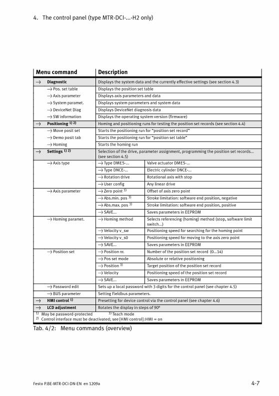
4. The control panel (type MTR-DCI-...-H2 only)
4-7Festo P.BE-MTR-DCI-DN-EN en 1209a
Menu command Description
Diagnostic Displays the system data and the currently effective settings (see section 4.3)
Pos. set table Displays the position set table
Axis parameter Displays axis parameters and data
System paramet. Displays system parameters and system data
DeviceNet Diag Displays DeviceNet diagnosis data
SW information Displays the operating system version (firmware)
Positioning 1) 2) Homing and positioning runs for testing the position set records (see section 4.4)
Move posit set Starts the positioning run for “position set record”
Demo posit tab Starts the positioning run for “position set table”
Homing Starts the homing run
Settings 1) 2) Selection of the drive, parameter assignment, programming the position set records...(see section 4.5)
Axis type Type DMES-... Valve actuator DMES-...
Type DNCE-... Electric cylinder DNCE-...
Rotation drive Rotational axis with stop
User config Any linear drive
Axis parameter Zero point 3) Offset of axis zero point
Abs.min. pos 3) Stroke limitation: software end position, negative
Abs.max. pos 3) Stroke limitation: software end position, positive
SAVE... Saves parameters in EEPROM
Homing paramet. Homing method Selects referencing (homing) method (stop, software limitswitch...)
Velocity v_sw Positioning speed for searching for the homing point
Velocity v_s0 Positioning speed for moving to the axis zero point
SAVE... Saves parameters in EEPROM
Position set Position nr. Number of the position set record (0...14)
Pos set mode Absolute or relative positioning
Position 3) Target position of the position set record
Velocity Positioning speed of the position set record
SAVE... Saves parameters in EEPROM
Password edit Sets up a local password with 3 digits for the control panel (see chapter 4.5)
BUS parameter Setting Fieldbus parameters.
HMI control 1) Presetting for device control via the control panel (see chapter 4.6)
LCD adjustment Rotates the display in steps of 90°1) May be password-protected 3) Teach mode2) Control interface must be deactivated; see [HMI control] :HMI = on
Tab. 4/2: Menu commands (overview)

4. The control panel (type MTR-DCI-...-H2 only)
4-8 Festo P.BE-MTR-DCI-DN-EN en 1209a
4.3 [Diagnostic] menu
For displaying the currently active settings of the position settable, axis and system parameters, status and diagnosticinformation on bus communication, and the firmware version:
1. From the main menu, select the [Diagnostic] menu.
2. Select a menu command (see Tab. 4/4).
<- -> You can page through the data using the arrowbuttons.
ESC Pressing the <Menu> button returns you to thehigher menu level.
Diagnostic
Pos.set tableAxis parameter
System paramet..DeviceNet Diag
SW information

4. The control panel (type MTR-DCI-...-H2 only)
4-9Festo P.BE-MTR-DCI-DN-EN en 1209a
Menu command Description
[Pos. set table] Nr The number of the position set record
a/r – a = absolute positioning,
– r = relative positioning
Pos Target position
Vel Positioning speed
[Axis parameter] 1) v max Maximum positioning speed
x min Stroke limitation: Software end position, negative
x max Stroke limitation: Software end position, positive
x 0 Offset of the axis zero point
feed 2) Feed constant
[System param] V power Supply voltage [V]
I max Maximum current [A]
I act Current current [A]
Temp Operating temperature [°C]
Cycle Number of positioning movements
Ref.switch Reference switch (ON/OFF)
Mode Units of measurement e.g. mm
Hom.meth. – bl.pos Fixed stop in positive direction
– bl.neg Fixed stop in negative direction
– sw.pos Reference switch in positive direction
– sw.neg Reference switch in negative direction
Gear Gear reduction ratio of the drive (e.g. 6.75)
1) Unit of measurement depends on the measuring system set2) Not for axis type “Rotation drive”
Tab. 4/3: [Diagnostic] menu (1)

4. The control panel (type MTR-DCI-...-H2 only)
4-10 Festo P.BE-MTR-DCI-DN-EN en 1209a
Menu command Description
[DeviceNet-Diag] Bus diagnosis
– No Power /BUS-Off
Bus supply is not connected or the Fieldbus is not cor-rectly parameterised. Connection to the master is notpossible.
– Device Oper-ational
DeviceNet is in the “Data exchange” state and is con-nected to a master.
– Device inStandby
No connection to the DeviceNet master exists, device isready for operation.
– Minor Fault A recoverable fault has occurred (e.g. Timeout)
– UnrecoverableFault
A severe, unrecoverable fault has occurred (e.g. dupli-cate MAC ID), a reset is required to bring the device backinto operation.
Bit rate Set bit rate of the MTR-DCI:Values:125 k, 250k, 500 k(bit/s)
I/O data length I/O data length setting.
– 8 bytes: only for the FHPP standard (control of the
MTR-DCI is done as per the Festo Handling and Posi-tioning Profile)
– 16 bytes: FHPP standard and FPC (additional use of
the FPC for parameterising the MTR-DCI)
MAC ID DeviceNet address of the MTR-DCI(hexadecimal/decimal).
[SW information] MTR-DCI firmware version, e. g. V 1.20
Tab. 4/4: [Diagnostic] menu (2)
4. The control panel (type MTR-DCI-...-H2 only)
4-11Festo P.BE-MTR-DCI-DN-EN en 1209a
4.4 [Positioning] menu
WarningInjuries or damage to mechanical components.
With all positioning procedures, the motor turns and theconnected axis starts to move.
• Make sure that:
– Nobody can place their hands into the positioningrange.
– There are no objects within the positioning range.
Note• Before starting a homing run, make sure that:
– The positioning system is set up and wiredcompletely, and is supplied with power.
– Parameterising is completed.
• Do not start a positioning run until the reference systemhas been defined by homing (see chapter 4.4.3).
NoteNote that position set records with speed v=0 or an invalidtarget position (-> fault TARGET POSITION OUT OF LIMIT)will not be executed.

Move position set
Position no.:[1...31] = _?
ESC <Menu>
EDIT <--> OK <Enter>
Move position set
Attention! Motor moves
ESC <Menu>
START <Enter>
4. The control panel (type MTR-DCI-...-H2 only)
4-12 Festo P.BE-MTR-DCI-DN-EN en 1209a
For selecting a positioning run or a homing run:
1. From the main menu, select the [Positioning] menu.
2. Select the menu command:
– [Move position set] to test a particular positioning setin the positioning set table (see chapter 4.4.1).
– [Demo posit tab] to run all position set records in theposition set table one after the other.
– [Homing] Homing run to determine the dimensionalreference system (see chapter 4.4.3).
4.4.1 [Positioning] [Move position set]
NoteDo not start a position set record until the referencesystem has been defined by homing.
To test a particular position set record in the position settable:
1. Select the position set number.
<- -> Select the desired number using the arrow buttons.
OK Confirm the selection using the <Enter> button.
ESC Pressing the <Menu> button cancels the action andreturns you to the higher menu level.
2. Start positioning with START <Enter>.
During the positioning run, the following information is dis-played:
– The active positioning set, e.g. Pos 2
Positioning
Move position setDemo posit tab
Homing

Move position set
Pos 2xt = 220 mm
v = 22 mm/sxa = 200 mm
EMERG.STOP<Menu>
Move posit set
Pos 2xt = 220 mm/s
v = 22 mm/sxa = 220 mm/s
ESC<Menu>
Demo position table
Attention! Motor moves
ESC <Menu>
START <Enter>
Demo position table
Pos 2xt = 220 mm
v = 22 mm/sxa = 220 mm
DEMO STOP<Enter>EMERG.STOP<Menu>
4. The control panel (type MTR-DCI-...-H2 only)
4-13Festo P.BE-MTR-DCI-DN-EN en 1209a
– The target position xt
– The positioning speed, v
– The current position xa
EMERG.STOP
Pressing the <Menu> button cancels the currentpositioning run (> Fault MOTOR STOP).
After the positioning run is finished:
ESC Pressing the <Menu> button returns you to theselection of the positioning set.
4.4.2 [Positioning] [Demo position table]
There must be at least two positioning sets in the memory.If the position set table contains a position set record withspeed v = 0, this position set record and all the followingrecords will not be executed; the positioning run will continuewith the first position set record.
To run all positioning sets in the position set table one afteranother:
• Start positioning with START <Enter>.
During the positioning run, the following information is dis-played:
– The active positioning set, e.g. Pos 2
– The target position xt
– The positioning speed, v
– The current position xa
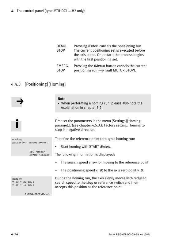
Homing
Attention! Motor moves.
ESC <Menu>
START <Enter>
Homing
V_sw = 20 mm/sv_s0 = 10 mm/s
EMERG.STOP<Menu>
4. The control panel (type MTR-DCI-...-H2 only)
4-14 Festo P.BE-MTR-DCI-DN-EN en 1209a
DEMO.STOP
Pressing <Enter> cancels the positioning run.The current positioning set is executed beforethe axis stops. On restart, the process beginswith the first positioning set.
EMERG.STOP
Pressing the <Menu> button cancels the currentpositioning run (> Fault MOTOR STOP).
4.4.3 [Positioning] [Homing]
Note• When performing a homing run, please also note theexplanation in chapter 5.2.
First set the parameters in the menu [Settings] [Homingparamet.]. (see chapter 4.5.3.). Factory setting: Homing tostop in negative direction.
To define the reference point through a homing run:
• Start homing with START <Enter>.
The following information is displayed:
– The search speed v_sw for moving to the reference point
– The positioning speed v_s0 to the axis zero point v_0.
During the homing run, the axis slowly moves with reducedsearch speed to the stop or reference switch and thenaccepts this position as the reference point.

4. The control panel (type MTR-DCI-...-H2 only)
4-15Festo P.BE-MTR-DCI-DN-EN en 1209a
EMERG.STOP
Pressing the <Menu> button cancels the homingrun (> Fault HOMING ERROR).
• Acknowledge the error message with<Enter>.
• Repeat the homing run.
After a successful homing run, the [Positioning] menu is dis-played.
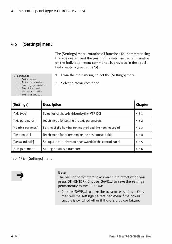
4. The control panel (type MTR-DCI-...-H2 only)
4-16 Festo P.BE-MTR-DCI-DN-EN en 1209a
4.5 [Settings] menu
The [Settings] menu contains all functions for parameterisingthe axis system and the positioning sets. Further informationon the individual menu commands is provided in the speci-fied chapters (see Tab. 4/5).
1. From the main menu, select the [Settings] menu
2. Select a menu command.
[Settings] Description Chapter
[Axis type] Selection of the axis driven by the MTR-DCI 4.5.1
[Axis parameter] Teach mode for setting the axis parameters 4.5.2
[Homing paramet.] Setting of the homing run method and the homing speed 4.5.3
[Position set] Teach mode for programming the position set table 4.5.4
[Password edit] Set up a local 3-character password for the control panel 4.5.5
[BUS parameter] Setting Fieldbus parameters 4.5.6
Tab. 4/5: [Settings] menu
NoteThe pre-set parameters take immediate effect when youpress OK <ENTER>. Choose [SAVE...] to save the settingspermanently to the EEPROM:
• Choose [SAVE...] to save the parameter settings. Onlythen will the settings be retained even if the powersupply is switched off or if there is a power failure.
Settings
Axis typeAxis parameter
Homing paramet.Position set
Password editBUS parameter
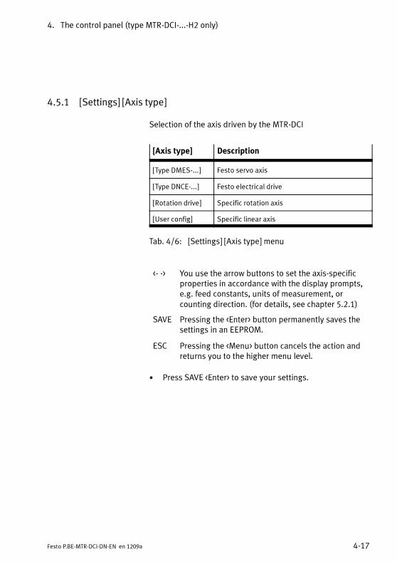
4. The control panel (type MTR-DCI-...-H2 only)
4-17Festo P.BE-MTR-DCI-DN-EN en 1209a
4.5.1 [Settings] [Axis type]
Selection of the axis driven by the MTR-DCI
[Axis type] Description
[Type DMES-...] Festo servo axis
[Type DNCE-...] Festo electrical drive
[Rotation drive] Specific rotation axis
[User config] Specific linear axis
Tab. 4/6: [Settings] [Axis type] menu
<- -> You use the arrow buttons to set the axis-specificproperties in accordance with the display prompts,e.g. feed constants, units of measurement, orcounting direction. (for details, see chapter 5.2.1)
SAVE Pressing the <Enter> button permanently saves thesettings in an EEPROM.
ESC Pressing the <Menu> button cancels the action andreturns you to the higher menu level.
• Press SAVE <Enter> to save your settings.
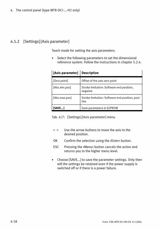
4. The control panel (type MTR-DCI-...-H2 only)
4-18 Festo P.BE-MTR-DCI-DN-EN en 1209a
4.5.2 [Settings] [Axis parameter]
Teach mode for setting the axis parameters.
• Select the following parameters to set the dimensionalreference system. Follow the instructions in chapter 5.2.4.
[Axis parameter] Description
[Zero point] Offset of the axis zero point
[Abs.min.pos] Stroke limitation: Software end position,negative
[Abs.max.pos] Stroke limitation: Software end position, posi-tive
[SAVE...] Save parameters in EEPROM
Tab. 4/7: [Settings] [Axis parameter] menu
<- -> Use the arrow buttons to move the axis to thedesired position.
OK Confirm the selection using the <Enter> button.
ESC Pressing the <Menu> button cancels the action andreturns you to the higher menu level.
• Choose [SAVE...] to save the parameter settings. Only thenwill the settings be retained even if the power supply isswitched off or if there is a power failure.

4. The control panel (type MTR-DCI-...-H2 only)
4-19Festo P.BE-MTR-DCI-DN-EN en 1209a
4.5.3 [Settings] [Homing paramet.]
Setting of the homing run method and the homing speed.Follow the instructions in chapter 5.2.2.
The maximum speed during homing is limited to half themaximum positioning speed v_max (for v_max see[Diagnostic] [Axis param] ).
[Hom. paramet.] Param. Description
[Homing method] sw.neg(switch negative)
Homing to reference switch, negative = factory setting
sw.pos(switch positive)
Homing to reference switch, positive
bl.neg(block negative)
Homing to fixed stop, negative
bl.pos(block positive)
Homing tofixed stop, positive
[Velocity v_sw] v_sw Speed for searching for the homing point
[Velocity v_s0] v_s0 Speed for moving to the axis zero point
[SAVE...] Save parameters in EEPROM
Tab. 4/8: [Settings] [Homing paramet.] menu
• Choose [SAVE...] to save the parameter settings.

4. The control panel (type MTR-DCI-...-H2 only)
4-20 Festo P.BE-MTR-DCI-DN-EN en 1209a
4.5.4 [Settings] [Position set]
Programming the position set table
• First select the desired position set number. The followingsettings related to the currently selected positioning set.When performing a homing run, please also note theexplanation in chapter 5.2.5.
[Position set] Param. Description
[Position nr.] Nr The number of the position set record
[Pos set mode] [abso-lute/relative]
Positioning modeabsolute = absolute position specification, related to the pro-ject zero pointrelative = relative position specification, related to the currentposition
[Position] xt Teach mode for setting the target position in the selected units ofmeasurement, e.g. [mm].Do not teach the positions until the reference system has beendefined by homing. (see chapter 4.4.3).
[Velocity] v Positioning speed in the selected system of measuremente.g. [mm/s]
[SAVE...] Save parameters in EEPROM
Tab. 4/9: [Settings] [Position set] menu
<- -> Use the arrow buttons to move the axis to thedesired position or select the parameter setting.
OK Confirm the selection using the <Enter> button.
ESC Pressing the <Menu> button cancels the action andreturns you to the higher menu level.
• Choose [SAVE...] to save the parameter settings. Only thenwill the settings be retained even if the power supply isswitched off or if there is a power failure.

4. The control panel (type MTR-DCI-...-H2 only)
4-21Festo P.BE-MTR-DCI-DN-EN en 1209a
4.5.5 [Settings] [Password edit]
In order to prevent unauthorised or unintentional overwritingor modification of parameters in the device, access via thecontrol panel can be protected by a “local” password. Nopassword has been preset at the factory (presetting = 000).
• Keep the password for the MTR-DCI in a suitable location,such as in the internal documentation pack for yoursystem.
If the active password in the MTR-DCI is lost in spite of carebeing taken:If needed, the password can be deleted by entering a masterpassword. In this case please contact your Festo Servicepartner.
Activating the password
Select [Settings] [Password edit] in the menu.
Enter a password with 3 digits (0..9). The current entryposition is marked with a question mark.
1. Use the arrow keys to select a digit.
2. Confirm your entry with <Enter>.
3. Set a number for the next input position “?”.
4. After selecting the third digit, save the password withSAVE <Enter>.
After saving the password, access to all parameterisation andcontrol functions in the control panel is locked by a pass-word query.
New Password:
[?xx] =
ESC <Menu>EDIT <--> OK <Enter>
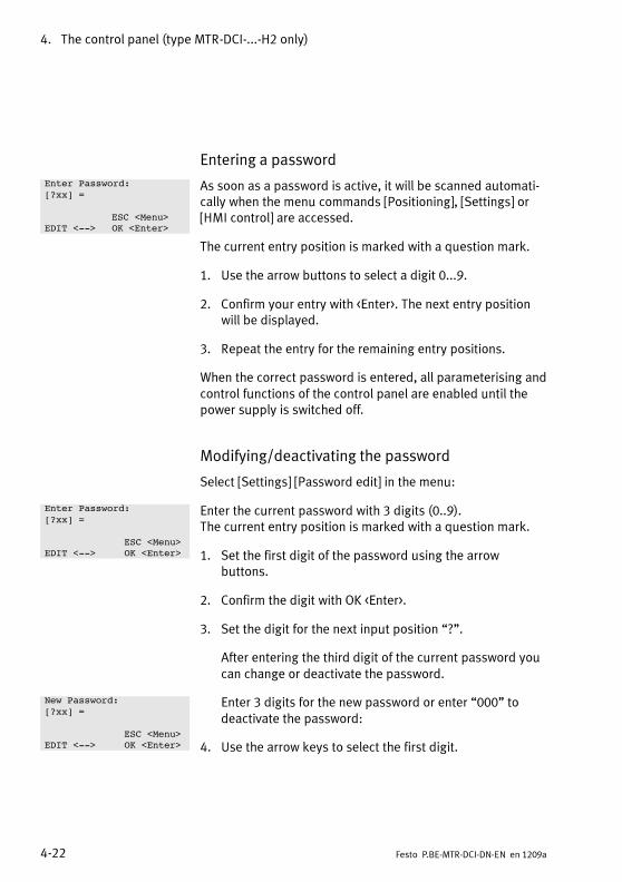
Enter Password:
[?xx] =
ESC <Menu>EDIT <--> OK <Enter>
Enter Password:
[?xx] =
ESC <Menu>EDIT <--> OK <Enter>
New Password:
[?xx] =
ESC <Menu>EDIT <--> OK <Enter>
4. The control panel (type MTR-DCI-...-H2 only)
4-22 Festo P.BE-MTR-DCI-DN-EN en 1209a
Entering a password
As soon as a password is active, it will be scanned automati-cally when the menu commands [Positioning], [Settings] or[HMI control] are accessed.
The current entry position is marked with a question mark.
1. Use the arrow buttons to select a digit 0...9.
2. Confirm your entry with <Enter>. The next entry positionwill be displayed.
3. Repeat the entry for the remaining entry positions.
When the correct password is entered, all parameterising andcontrol functions of the control panel are enabled until thepower supply is switched off.
Modifying/deactivating the password
Select [Settings] [Password edit] in the menu:
Enter the current password with 3 digits (0..9).The current entry position is marked with a question mark.
1. Set the first digit of the password using the arrowbuttons.
2. Confirm the digit with OK <Enter>.
3. Set the digit for the next input position “?”.
After entering the third digit of the current password youcan change or deactivate the password.
Enter 3 digits for the new password or enter “000” todeactivate the password:
4. Use the arrow keys to select the first digit.

4. The control panel (type MTR-DCI-...-H2 only)
4-23Festo P.BE-MTR-DCI-DN-EN en 1209a
5. Confirm the digit with OK <Enter>.
6. Set the digit for the next input position “?”.
7. After entering the third digit, save your setting with SAVE<Enter>.
4.5.6 [Settings] [BUS parameter]
Setting Fieldbus parameters.
[BUS parameter] Param. Description
[MAC ID] 0 ... 63(0 ...3fh)
Fieldbus address of the MTR-DCI.Representation:“0 dec, 0 hex”...“63 dec, 3f hex”
[Bit rate] 500 kbit/s,250 kbit/s,125 kbit/s
Fieldbus bit rate corresponding to the settings on the master.
[I/O DATA] 8 bytes16 bytes
I/O data length setting
– 8 bytes: only for the FHPP standard (control of the MTR-DCI
is done as per the Festo Handling and Positioning Profile)
– 16 bytes: FHPP standard and FPC (additional use of theFesto Parameter Channel for parameterising the MTR-DCI)
Tab. 4/10: [Settings] [BUS Parameter] menu
<- -> Select the parameter setting using the arrowbuttons.
OK Confirm the selection using the <Enter> button.
ESC Pressing the <Menu> button cancels the action andreturns you to the higher menu level.
The settings made in the [BUS Parameter] menu are saveddirectly and permanently (including in the event of a powerfailure) to the EEPROM when you confirm them withOK<Enter>.

4. The control panel (type MTR-DCI-...-H2 only)
4-24 Festo P.BE-MTR-DCI-DN-EN en 1209a
4.6 Menu command [HMI control]
To select the [Positioning] and [Settings] menu commands the“HMI: on” setting is required. Only then is the MTR-DCI readyto process user entries on the control panel.When selecting the menu commands, you will be prompted tomodify the HMI setting.
You can also change the setting directly by selecting the [HMIcontrol] menu item.
HMI 1) Description
on Device control is carried out manually via the control panel. The control interface of theMTR-DCI is deactivated and control enable is set. The actual status of the FHPP controlbytes or the transmitted DS402 control word then has no effect.When control panel control is active the drive cannot be stopped with the STOP bit.
off Device control is carried out via the control interface of the MTR-DCI.
1) HumanMachine Interface
Tab. 4/11: States [HMI control]
<- -> Select the parameter setting using the arrowbuttons.
OK Confirm the selection using the <Enter> button.
ESC Pressing the <Menu> button cancels the action andreturns you to the higher menu level.
Access to the MTR-DCI via HMI and FCT can be blocked viathe Fieldbus in the following manner:
– FHPP: Bit CCON.B5, “HMI Access locked”.
HMI control
[on/off] = on?
HMI Access freeESC <Menu>
<--> OK <Enter>

Commissioning
5-1Festo P.BE-MTR-DCI-DN-EN en 1209a
Chapter 5
Commissioning
5. Commissioning
5-2 Festo P.BE-MTR-DCI-DN-EN en 1209a
Contents
5. Commissioning 5-1. . . . . . . . . . . . . . . . . . . . . . . . . . . . . . . . . . . . . . . . . . . . . . . .
5.1 Commissioning procedure 5-4. . . . . . . . . . . . . . . . . . . . . . . . . . . . . . . . . . . . . . . .
5.2 Commissioning with the control panel (MTR-DCI-...-H2 only) 5-7. . . . . . . . . . . .
5.2.1 Setting the axis type 5-9. . . . . . . . . . . . . . . . . . . . . . . . . . . . . . . . . . . . .
5.2.2 Setting the homing parameters 5-10. . . . . . . . . . . . . . . . . . . . . . . . . . . .
5.2.3 Starting homing 5-13. . . . . . . . . . . . . . . . . . . . . . . . . . . . . . . . . . . . . . . . .
5.2.4 Teaching the axis zero point AZ and the software end positions 5-15. .
5.2.5 Teaching position set records 5-17. . . . . . . . . . . . . . . . . . . . . . . . . . . . . .
5.2.6 Test run 5-18. . . . . . . . . . . . . . . . . . . . . . . . . . . . . . . . . . . . . . . . . . . . . . .
5.2.7 Setting bus parameters 5-20. . . . . . . . . . . . . . . . . . . . . . . . . . . . . . . . . . .
5.3 Commissioning with FCT 5-23. . . . . . . . . . . . . . . . . . . . . . . . . . . . . . . . . . . . . . . . .
5.3.1 Installing the FCT 5-23. . . . . . . . . . . . . . . . . . . . . . . . . . . . . . . . . . . . . . . .
5.3.2 Procedure 5-24. . . . . . . . . . . . . . . . . . . . . . . . . . . . . . . . . . . . . . . . . . . . .
5.3.3 Further information on FCT 5-25. . . . . . . . . . . . . . . . . . . . . . . . . . . . . . . .
5.4 Commissioning a DeviceNet master 5-27. . . . . . . . . . . . . . . . . . . . . . . . . . . . . . . .
5.4.1 Overview of commissioning on the Fieldbus 5-27. . . . . . . . . . . . . . . . . .
5.4.2 Configuration of the DeviceNet master (“I/O configuration”) 5-28. . . .
5.5 Festo profile for handling and positioning (FHPP) 5-30. . . . . . . . . . . . . . . . . . . . .
5.5.1 Supported operating modes 5-30. . . . . . . . . . . . . . . . . . . . . . . . . . . . . . .
5.5.2 Structure of the cyclic I/O data (FHPP standard) 5-32. . . . . . . . . . . . . .
5.5.3 Description of the I/O data (record selection) 5-34. . . . . . . . . . . . . . . . .
5.5.4 Description of the I/O data (direct task) 5-35. . . . . . . . . . . . . . . . . . . . .
5.5.5 Description of the control bytes CCON, CPOS, CDIR 5-36. . . . . . . . . . . .
5.5.6 Description of the status bytes SCON, SPOS, SDIR (RSB) 5-39. . . . . . .
5.5.7 Examples of I/O data 5-42. . . . . . . . . . . . . . . . . . . . . . . . . . . . . . . . . . . . .
5.6 Sequence control according to the FHPP standard 5-55. . . . . . . . . . . . . . . . . . . .
5.6.1 Homing 5-55. . . . . . . . . . . . . . . . . . . . . . . . . . . . . . . . . . . . . . . . . . . . . . . .
5.6.2 Jog mode 5-57. . . . . . . . . . . . . . . . . . . . . . . . . . . . . . . . . . . . . . . . . . . . . .
5.6.3 Teaching via Fieldbus 5-59. . . . . . . . . . . . . . . . . . . . . . . . . . . . . . . . . . . .
5.6.4 Record selection (Positioning mode) 5-61. . . . . . . . . . . . . . . . . . . . . . . .

5. Commissioning
5-3Festo P.BE-MTR-DCI-DN-EN en 1209a
5.6.5 Direct task (Positioning mode, Force mode) 5-67. . . . . . . . . . . . . . . . . .
5.6.6 Standstill monitoring 5-74. . . . . . . . . . . . . . . . . . . . . . . . . . . . . . . . . . . . .
5.7 The Festo Parameter Channel (FPC) 5-76. . . . . . . . . . . . . . . . . . . . . . . . . . . . . . . .
5.7.1 Structure of the cyclic I/O data (FHPP-FPC) 5-76. . . . . . . . . . . . . . . . . . .
5.7.2 Request identifiers, response identifiers and error numbers 5-78. . . . .
5.7.3 Rules for request-response processing 5-81. . . . . . . . . . . . . . . . . . . . . .
5.7.4 Parameterisation example 5-83. . . . . . . . . . . . . . . . . . . . . . . . . . . . . . . .
5.8 FHPP finite state machine 5-85. . . . . . . . . . . . . . . . . . . . . . . . . . . . . . . . . . . . . . . .
5.8.1 Establish “ready to operate” status 5-87. . . . . . . . . . . . . . . . . . . . . . . . .
5.8.2 Positioning 5-88. . . . . . . . . . . . . . . . . . . . . . . . . . . . . . . . . . . . . . . . . . . . .
5.9 Notes on operation 5-90. . . . . . . . . . . . . . . . . . . . . . . . . . . . . . . . . . . . . . . . . . . . . .
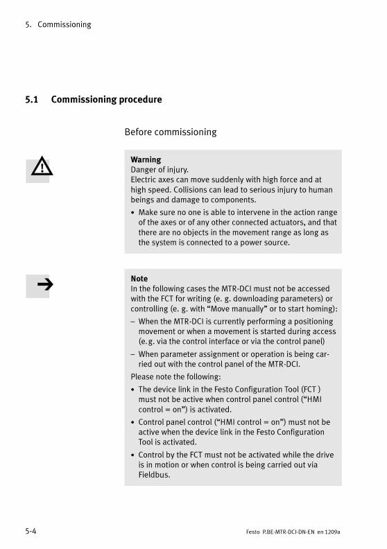
5. Commissioning
5-4 Festo P.BE-MTR-DCI-DN-EN en 1209a
5.1 Commissioning procedure
Before commissioning
WarningDanger of injury.Electric axes can move suddenly with high force and athigh speed. Collisions can lead to serious injury to humanbeings and damage to components.
• Make sure no one is able to intervene in the action rangeof the axes or of any other connected actuators, and thatthere are no objects in the movement range as long asthe system is connected to a power source.
NoteIn the following cases the MTR-DCI must not be accessedwith the FCT for writing (e. g. downloading parameters) orcontrolling (e. g. with “Move manually” or to start homing):
– When the MTR-DCI is currently performing a positioningmovement or when a movement is started during access(e.g. via the control interface or via the control panel)
– When parameter assignment or operation is being car-ried out with the control panel of the MTR-DCI.
Please note the following:
• The device link in the Festo Configuration Tool (FCT )must not be active when control panel control (“HMIcontrol = on”) is activated.
• Control panel control (“HMI control = on”) must not beactive when the device link in the Festo ConfigurationTool is activated.
• Control by the FCT must not be activated while the driveis in motion or when control is being carried out viaFieldbus.

5. Commissioning
5-5Festo P.BE-MTR-DCI-DN-EN en 1209a
• Before commissioning the drive make sure that:
– The work space is of sufficient size for operation witha work load.
– The work load does not collide with the motor or thegear of the axis when the slide moves into the endposition.
• Please observe the notes in the operating instructions foryour axis.
Switching on
NoteNote that the tolerance for the supply voltage must beobserved. The tolerance must also be observed directly atthe operating voltage connection of the MTR-DCI (seechapter 3.3).
Note• When the power supply is switched off, wait for approx.5 seconds before switching the device on again.
When the logic voltage is connected via the Fieldbus adapter:
Switch-on sequence Do not switch on the logic voltage after the load voltage,since this may cause the MTR-DCI to switch off and back onagain (= reset).
Logic voltage failure If the logic voltage fails, the controller will switch off.MTR-DCI 42, 52, 62: if the load voltage is still active, thecontroller will switch back on but will lose its reference posi-tion.

5. Commissioning
5-6 Festo P.BE-MTR-DCI-DN-EN en 1209a
1. Switch on the power supply for the MTR-DCI. When thepower supply is switched on, the MTR-DCI automaticallycarries out an internal check. Preset operating mode afterswitch-on: record selection.
2. Carry out parameterising and commissioning with thecontrol panel or the FCT, as described in the followingchapters or in the FCT/plug-in help.
3. In order to complete commissioning note the instructionsfor operation in the FCT/plug-in help and in section 5.9.
NoteTo restore the default settings the EEPROM can be deletedif necessary with CI object 20F1 (Data memory control)directly via the serial interface (see section C.1). User-specific settings will then be lost.
• Use CI commands only if you already have experience ofusing Service Data Objects.
• If necessary consult Festo.
WarningDanger of injury.
Faults in parameterisation can cause injury to humanbeings and damage to property. To ensure correct settingof the reference coordinates and the operating range it isessential to perform a homing run in the following cases:
– On initial commissioning,
– After a change of homing method,
– Every time the logic voltage supply is connected!

5. Commissioning
5-7Festo P.BE-MTR-DCI-DN-EN en 1209a
5.2 Commissioning with the control panel (MTR-DCI-...-H2 only)
The control panel provides all the necessary functions forcommissioning, parameterisation, diagnosis and operatorcontrol directly at the MTR-DCI. Positioning records and para-meters can be edited using the menu system. You can use theTeach functions to easily move to positions and load theseinto the position set table.
NoteThe project zero point PZ can only be set via FCT or byusing the CI object 21F4h (FHHP PNU 500).
Information on the button functions and on the menu com-position of the control panel can be found in Chapter 4.
Device control
In order that the control panel can control the connectedMTR-DCI, the control interface of the MTR-DCI must be deacti-vated and control panel enable must be set [HMI = on]. Theactual status of the FHPP control bit has no effect after this.
You will find information on the control enable in section 4.6.
Overview of parameter assignment andcommissioning
Information on the current parameter assignment of themotor unit can be found in the menu [Diagnostic] on thecontrol panel.
Carry out the following steps in order to commission theMTR-DCI the first time with the control panel. Refer to thedetailed description in the chapters specified.
Diagnostic
PositioningSettings
HMI control
LCD adjustment

5. Commissioning
5-8 Festo P.BE-MTR-DCI-DN-EN en 1209a
Commissioning (overview) Chap.
1. Select the drive type and adapt the parameters to youraxis as necessary.
5.2.1
2. Set the following parameters for homing:– Homing method,– search speed to reference point,– positioning speed to axis zero point,
5.2.2
3. Carry out homing.– In the “fixed stop ...” homing method:
teach an axis zero point ≠ 0.
5.2.3
4. To define the axis zero point and the operating rangeteach-in the following axis parameters:
– Axis zero offset to reference point
– Positive and negative software end positions.
5.2.4
5. Enter multiple positioning sets (target position, posi-tioning mode, travel speed and accelerations).
5.2.5
6. Perform a test run to test the positioning response of theaxis, the reference coordinates and the operating range.
5.2.6
7. Optimise the positioning set configuration and the refer-ence coordinate and operating range settings asnecessary.
5.2.5
8. Switch on the Fieldbus interface of the MTR-DCI.This step may optionally be carried out first.
5.2.7and5.4.1
9. To complete the commissioning process refer to theinformation relating to operation of the unit.
5.9
Tab. 5/1: Commissioning steps
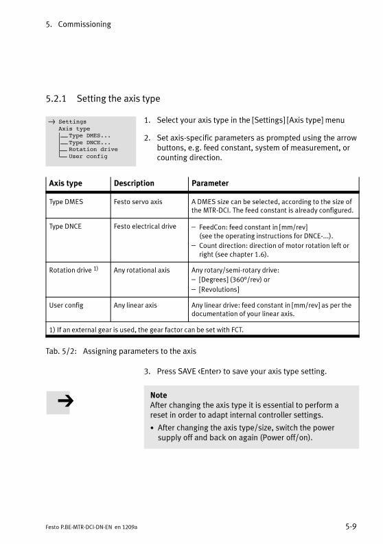
5. Commissioning
5-9Festo P.BE-MTR-DCI-DN-EN en 1209a
5.2.1 Setting the axis type
1. Select your axis type in the [Settings] [Axis type] menu
2. Set axis-specific parameters as prompted using the arrowbuttons, e.g. feed constant, system of measurement, orcounting direction.
Axis type Description Parameter
Type DMES Festo servo axis A DMES size can be selected, according to the size ofthe MTR-DCI. The feed constant is already configured.
Type DNCE Festo electrical drive – FeedCon: feed constant in [mm/rev](see the operating instructions for DNCE-...).
– Count direction: direction of motor rotation left orright (see chapter 1.6).
Rotation drive 1) Any rotational axis Any rotary/semi-rotary drive:
– [Degrees] (360°/rev) or
– [Revolutions]
User config Any linear axis Any linear drive: feed constant in [mm/rev] as per thedocumentation of your linear axis.
1) If an external gear is used, the gear factor can be set with FCT.
Tab. 5/2: Assigning parameters to the axis
3. Press SAVE <Enter> to save your axis type setting.
NoteAfter changing the axis type it is essential to perform areset in order to adapt internal controller settings.
• After changing the axis type/size, switch the powersupply off and back on again (Power off/on).
Settings
Axis typeType DMES...
Type DNCE...Rotation drive
User config

5. Commissioning
5-10 Festo P.BE-MTR-DCI-DN-EN en 1209a
5.2.2 Setting the homing parameters
Information on homing to a reference switch
NoteDamage to components.
The slide may only move directly against a fixed stop if themaximum permitted impact energy is not exceeded (im-pact energy = 0.5 x mass x speed2).
• The permitted value can be found in the description foryour positioning axis.
• If necessary, reduce the speed at which movement to thestop is made. The speed can amount to 0 % to 50 % ofthe rated speed.
• When referencing to a stop, set the offset of the axis zeropoint ≠ 0 (see chapter 5.2.4).
• Protect sensitive stops by limiting the motor current.
The positioning axis DMES-... can conduct a homing run withthe preset current limitation (150 %). The current limitationneed not be modified.
Current limitation When the max. motor current is reached and the motor isstationary, the MTR-DCI will detect a stop. The maximummotor current during homing can be specified as 10...200 %of the rated motor current (see FCT help or CI object 66073h).
Note– If the drive is arranged vertically, an increase in themotor current may be necessary. If the motor current istoo low, homing cannot be carried out or the unit maydetect a stop incorrectly.
– The set required speed cannot be reached if currentlimitation is too great.

5. Commissioning
5-11Festo P.BE-MTR-DCI-DN-EN en 1209a
Current limitation 1) 32 42 52 62
100 % Z1 x nominal motor current
Motor currentMotor torque
AmNm
0.7330
2.0110
5.0300
6.19700
150 % (default) Z1.5 x nominal motor current
Motor currentMotor torque
AmNm
1.146
3.0171
7.5460
9.291076
200 % Z2 x nominal motor current
Motor currentMotor torque
AmNm
1.4662
3.8 2)
2207.7 2)
47012.381450
1) Parameter specification in FCT: relative motor current in % of nominal current. Setting range10...200 %.
2) Due to maximum current limiting the value does not rise further.
Tab. 5/3: Current limitation
Setting parameters
1. Select the homing parameters in the [Settings][Homingparameter] menu (see Tab. 5/5).
2. Accept each setting with OK <Enter>. The setting will thentake effect in the drive.
3. Save the parameter settings with the [SAVE]menu com-mand.
Settings
Homing parameterHoming method
Velocity v_swVelocity v_s0
SAVE

5. Commissioning
5-12 Festo P.BE-MTR-DCI-DN-EN en 1209a
Factory settings 32 42 52 62
Speeds v_sw, v_s0 % 1)
inc/s~41 %27000
~22 %22400
~17 %16800
~15 %16800
Rated motor speed rot/sinc/s
5566000
50100000
50100000
56.7113400
Homing method Reference switch, negative (near motor)
1)%of the nominal motor speed; max. = 50 %
Tab. 5/4: Factory pre-setting for homing parameters
[Hom. paramet.] Param. Description
[Homing method] 1) sw.neg(switch negative)
Homing to reference switch, positive, negative
sw.pos(switch positive)
Homing to reference switch, positive
bl.neg(block negative)
Homing to fixed stop, negative
bl.pos(block positive)
Homing to fixed stop, positive
[Velocity v_sw] v_sw Speed for searching for the homing point
[Velocity v_s0] v_s0 Speed for moving to the axis zero point
[SAVE...] Save parameters in EEPROM
1) Further information on homing methods is provided in chapter 1.6.3.
Tab. 5/5: Homing parameters

5. Commissioning
5-13Festo P.BE-MTR-DCI-DN-EN en 1209a
CautionWhen the homing method is changed the axis zero offset isreset to zero. Any existing settings of the software endpositions and target positions in the positioning set tableare retained. Note that these values move together withthe axis zero point AZ.
• After changing the homing method always perform ahoming run.
• Then teach-in the axis zero offset.
If the axis zero point is modified:
• Teach-in the new software end positions and target posi-tions.
5.2.3 Starting homing
NoteNote that at the start the drive must be in front of the stopor reference switch in terms of the search direction (seechapter 1.6.3).
1. If necessary, position the drive in Teach mode so that,when viewed in terms of the search direction, it is in frontof the stop or reference switch at the start.
• Select e.g. [Settings] [Position set] [Position] (see alsosection 5.2.5).
• Move the drive to the desired position manually withthe arrow buttons.
• End the procedure with ESC <Menu> so that the posi-tion is not included in the position set table.
2. Select [Positioning] [Homing].
3. Start homing with START <Enter>.
Positioning
Demo posit tabMove posit set
Homing
5. Commissioning
5-14 Festo P.BE-MTR-DCI-DN-EN en 1209a
After a successful homing the drive stops at the axis zeropoint AZ. With first commissioning or when the homingmethod is changed, the offset of the axis zero point = 0; afterhoming the drive then stands at the homing point REF.
Discontinuing homing
If necessary, homing can be discontinued with the <Menu>button (EMERG STOP). If correct homing has already beencarried out, the previous homing point will retain its validity.
Error in the homing run
If the axis does not find a reference switch during homing, itkeeps moving until it encounters a stop. Then it comes to restat the stop and HOMING ERROR is displayed. Homing mustbe repeated after resetting the error message:
Reasons for this may be:
– Axis already positioned behind reference switch at start ofhoming,
– Reference switch defective,
– Axis defective or incorrectly mounted, e.g. clutch attach-ment slipping.
5. Commissioning
5-15Festo P.BE-MTR-DCI-DN-EN en 1209a
If a fault occurs during homing:
• Acknowledge the error message with <Enter>.
• If necessary, check the function of the reference switch.
• Check the settings of the parameters.
• If necessary, position the drive in Teach mode so that,when viewed in terms of the search direction, it is in frontof the stop or reference switch at the start.
• Repeat the homing run.
5.2.4 Teaching the axis zero point AZ and the software end positions
CautionDamage to components.
Movement to the mechanical end positions is not permit-ted during operation. During movement to the end posi-tions with a high load, the mechanical axis components(e.g. the lead screw) can block in the end positions.
• Set the offset of the axis zero point ≠ 0,e.g.+1.00 mm when referencing to a negative fixed stopor -1.00 mm when referencing to a positive fixed stop.
• Limit the positioning range by defining valid softwareend positions during commissioning (see section 1.6).
• Specify target positions within the permitted positioningrange only.
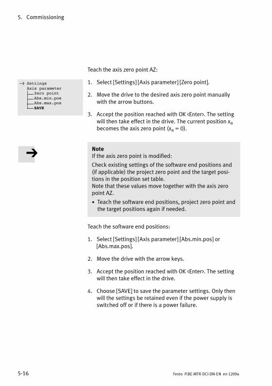
5. Commissioning
5-16 Festo P.BE-MTR-DCI-DN-EN en 1209a
Teach the axis zero point AZ:
1. Select [Settings] [Axis parameter] [Zero point].
2. Move the drive to the desired axis zero point manuallywith the arrow buttons.
3. Accept the position reached with OK <Enter>. The settingwill then take effect in the drive. The current position xabecomes the axis zero point (xa = 0).
NoteIf the axis zero point is modified:
Check existing settings of the software end positions and(if applicable) the project zero point and the target posi-tions in the position set table.Note that these values move together with the axis zeropoint AZ.
• Teach the software end positions, project zero point andthe target positions again if needed.
Teach the software end positions:
1. Select [Settings] [Axis parameter] [Abs.min.pos] or[Abs.max.pos].
2. Move the drive with the arrow keys.
3. Accept the position reached with OK <Enter>. The settingwill then take effect in the drive.
4. Choose [SAVE] to save the parameter settings. Only thenwill the settings be retained even if the power supply isswitched off or if there is a power failure.
Settings
Axis parameterZero point
Abs.min.posAbs.max.pos
SAVE

5. Commissioning
5-17Festo P.BE-MTR-DCI-DN-EN en 1209a
5.2.5 Teaching position set records
Enter the position set records as follows:
1. Activate the desired position record (1...31) with[Settings] [Position set] [Position nr].
2. Select the positioning mode of the position set:
• Select [Pos set mode].
• Set the positioning mode with the arrow keys:absolute= absolute position specification,
in relation to the project zero pointrelative = relative position specification,
in relation to the current position.
• Accept the value with OK <Enter>.
3. Teach the target position of the position record:
• Select [Position].
• Move the drive manually to the desired target positionwith the arrow keys.
• Accept the position reached with OK <Enter>. Thesetting of the target position and the positioningmode will then take effect in the drive.
4. Set the speed:
• Select [Velocity].
• Set the nominal speed with the arrow keys.
• Accept the setting with OK <Enter>. The setting willthen take effect in the drive.
Position records with speed v = 0 or invalid target positions(-> error TARGET POSITION OUT OF LIMIT) cannot beexecuted.
Settings
Position setPosition nr
Pos set modePosition
VelocitySAVE

5. Commissioning
5-18 Festo P.BE-MTR-DCI-DN-EN en 1209a
5. Select [SAVE] to save the positioning set. Only then willthe settings be retained even if the power supply isswitched off or if there is a power failure.
6. Enter the next position record.
Digitalisation errors of the analogue-digital converter canaccumulate in the case of relative position movements whichoccur frequently one after the other, leading to deviations ofthe position values. If necessary, insert an absolute positionset or a homing run into the positioning cycle, in order tocorrect deviations.
5.2.6 Test run
WarningInjury to persons and damage to property
With all positioning procedures, the motor turns and theconnected axis moves.
• Make sure that:
– Nobody can place their hands into the positioningrange,
– There are no objects within the positioning range.
CautionDamage to components
The unit must not move onto mechanical end positions(stops) during operation. When the unit moves to the endpositions with a heavy load, blockage may occur in the endpositions
• Limit the positioning range by defining valid softwareend positions during commissioning (see section 5.2.4).

5. Commissioning
5-19Festo P.BE-MTR-DCI-DN-EN en 1209a
1. Enter several position set records:
• Set target positions at the limits of the positioningrange in order to check the software end positions.
• Set different speeds.
2. Select [Positioning] [Move posit. set] in order to executea certain position set record — or —
3. Select [Positioning] [Demo posit tab] in order to processall position set records. At least two position set recordsmust be entered in the position set table in order to usethis function.
In the [Demo posit tab] positioning cycle, all position setrecords 1...31 in the position set table will be executedone after the other. If the position set table contains aposition set with speed v = 0, neither this position setrecord nor the following records will be executed; thepositioning cycle will continue from the first position setrecord.
4. Start the test run.
NoteWith EMERG.STOP <Menu> you can interrupt the currentpositioning procedure.
With DEMO STOP <Enter> you can interrupt the positioningcycle [Demo posit tab]. The current position set will beexecuted before the drive stops.
• Check the positioning behaviour.
• Check the position details displayed.
5. If necessary, optimise the settings for position sets, andalso (if needed) for the points of reference and theworking range.
Positioning
Demo posit tabMove posit set
Homing

5. Commissioning
5-20 Festo P.BE-MTR-DCI-DN-EN en 1209a
5.2.7 Setting bus parameters
Before commissioning on DeviceNet, valid bus parametersmust be set.
Station number (MAC-ID)
– Valid station numbers: 0 ... 63.
– The invalid station number 255 is preset (control paneldisplay: ???).This is to make sure that a correct address is set duringcommissioning or when replacing.
Recommendation:Assign the station numbers in ascending order. Adapt thestation numbering to the machinery infrastructure of yourplant.
NoteStation numbers can only be assigned once per Fieldbusline.
Set the station numbers as follows:
1. Select [Settings] [Bus parameter] [MAC ID] (see alsosection 4.5).
2. Press <Enter> to display the current setting.
3. Use the arrow keys to set the desired bit rate.
4. Accept the setting with OK “Enter”.The set bit rate is saved permanently and protectedagainst network failure.
NoteThe set bit rate will not take effect until after a power off/on process!
Settings
Bus parameterMAC ID
Baud rate
500 kBd
ESC ”Menu”
EDIT ”--” OK ”Enter”

5. Commissioning
5-21Festo P.BE-MTR-DCI-DN-EN en 1209a
Bit rate (bit rate)
– Possible bit rates:500 kbit, 250 kbit, 125 kbit
– An invalid bit rate is preset (display on the control panel:“???”).This ensures that a correct bit rate must be set duringcommissioning or replacement.
NoteAll of the participants on a fieldbus line must use the samebit rate. Otherwise no communication will be possible.
Set the bit rate as follows:
1. Choose [Settings] [Bus parameter] [Baudrate](see also section 4.5).
2. Press <Enter> to display the current setting.
3. Use the arrow keys to set the desired baud rate.
4. Accept the setting with OK <Enter>.The defined baud rate is permanently saved.
NoteThe defined baud rate only takes effect after a poweroff/on cycle!
Settings
Bus parameterBaudrate
Baudrate
500 kBd
ESC <Menu>
EDIT <--> OK <Enter>

5. Commissioning
5-22 Festo P.BE-MTR-DCI-DN-EN en 1209a
I/O data length
– Possible data lengths:
– 8 bytes (for sequence control as per the FHPPstandard)
– 16 bytes (8 bytes for sequence control as per theFHPP standard + an additional 8 bytes for parameter-ising via FHPP FPC)
– The default setting is an invalid data length(displayed on the control panel as “???”)This ensures that the correct data length has to beentered during commissioning or when replacing the unit.
Set the data length as follows:
1. Select [Settings] [Bus parameter] [I/O Datalength](see also section 4.5).
2. Press <Enter> to display the current setting.
3. Set the desired length with the arrow buttons.The setting must agree with the configuration of theDeviceNet master (see chapter 5.4.2).
4. Accept the setting with OK <Enter>.The set data length becomes effective immediately and issaved against power failure.
Settings
Bus parameterI/O Datalength
I/O Datalength
8 Byte I/O Data
ESC <Menu>
EDIT <--> OK <Enter>

5. Commissioning
5-23Festo P.BE-MTR-DCI-DN-EN en 1209a
5.3 Commissioning with FCT
The Festo Configuration Tool (FCT) is the software platform forconfiguring and commissioning different components anddevices from Festo.
The FCT consists of the following components:
– A framework as program start and entry point with uni-form project and data management for all supportedtypes of devices,
– A plug-in for the special demands of each device type(e.g. MTR-DCI) with the necessary descriptions and dia-logues. The plug-ins are managed and started from theframework.
The MTR-DCI plug-in for the Festo Configuration Tool supportsall the steps necessary to commission an MTR-DCI. With theMTR-DCI plug-in for the Festo Configuration Tool thenecessary parameter settings can be performed offline - thatis, without connecting the MTR-DCI to the PC. This enablesthe actual commissioning procedure to be prepared inadvance, such as in the design office when planning a plantsetup.
5.3.1 Installing the FCT
The FCT is installed on your PC with an installation program.The MTR-DCI plug-in is installed on your PC together with theFCT's installation program.
NoteAdministrator rights are required for installing the FCT.
5. Commissioning
5-24 Festo P.BE-MTR-DCI-DN-EN en 1209a
NoteAs of version V2.1.0, the plug-in MTR-DCI supports thefollowing motor units:
– MTR-DCI-...-DN: firmware version V1.00 and higher
• Check with later versions of the MTR-DCI to ascertainwhether an updated plug-in is provided. If necessaryconsult Festo.
1. Close all programs.
2. Place the Festo Configuration Tool CD in your CD ROMdrive. If Auto Run is activated on your system, the installa-tion will start automatically and you can omit steps 3and 4.
3. Select [Run] in the Start menu.
4. Enter D:\setup (if necessary replace D by the letter of yourCD ROM drive).
5. Follow the instructions on the screen.
5.3.2 Procedure
Starting the FCT
1. Connect the MTR-DCI to your PC via the RS232 port.Follow the instructions in section 3.4.
2. Start the FCT:Double-click the FCT icon on the desktop– or –Select the entry [Festo Software] [Festo ConfigurationTool] in the Windows [Start] menu.
3. Create a project in the FCT or open an existing project.Add a device to the project with the MTR-DCI plug-in.

5. Commissioning
5-25Festo P.BE-MTR-DCI-DN-EN en 1209a
4. Create the device connection (online connection) betweenthe PC and the MTR-DCI via the FCT tool bar. You mayneed to synchronise the device names.
Device control
In order that the FCT can control the connected MTR-DCI, thecontrol interface of the MTR-DCI must be deactivated and“control enable” must be set for the FCT (FCT/HMI = On). Theactual status of the ENABLE control bit then has no effect.
• Access the “Project output” window, “Operate” tab, thenunder “Device control” activate first the box “FCT/HMI”and then the box “Enable”.The control interface of the MTR-DCI will then be deacti-vated and control will be enabled for the FCT.
Access to the MTR-DCI by means of the Festo ConfigurationTool can be blocked via the DeviceNet interface (see section5.5.2, FHPP control bit CCON.B5, CiA 402 control word bit14).In this case the boxes “FCT control” and “Enable” are blocked(inactive).
5.3.3 Further information on FCT
Further information is provided in the Festo ConfigurationTool help:
FCT Help via the menu command [Help] [General FCT contents] e.g.
– for working with projects and on including a device in aproject,
– for defining the dimensional reference system (homingand reference coordinates),
– on setting the Fieldbus address.

5. Commissioning
5-26 Festo P.BE-MTR-DCI-DN-EN en 1209a
Plug-in help With the menu command [Help] [Contents of installed plugins][Festo (manufacturer name)] [MTR-DCI (Plug-In-Name)], e.g.:
– For describing the dialogues of the “Device MTR-DCI”,
– For describing the work steps for commissioning,
– For the basic functions: Device connection, Device namesand Device control, and for password protection.
Printed information In order to use the complete Help or parts of it without a PC,you can use one of the following options:
• With the button “Print” in the Help window, print indi-vidual Help pages or all the pages of a book directlyfrom the Help index.
• Print a prepared printed version of the Help in Adobe PDFformat or Rich Text Format (RTF):
Printedversion
Directory File
FCT help ...(FCT installation directory)\Help\ – FCT_de.pdf
– FCT_de.rtf
Plug-in help(MTR-DCI)
...(FCT installation directory)\HardwareFamilies\Festo\MTR-DCI\V...\Help\
– MTR-DCI_de.pdf
– MTR-DCI_de.rtf
To print in Adobe PDF format, you will require Adobe Reader.

5. Commissioning
5-27Festo P.BE-MTR-DCI-DN-EN en 1209a
5.4 Commissioning a DeviceNet master
The following sections describe the configuration and addres-sing of the MTR-DCI on a DeviceNet interface or a DeviceNetmaster. In order to understand this section you should befamiliar with DeviceNet and know the specification.
5.4.1 Overview of commissioning on the Fieldbus
The following steps are required for commissioning theMTR-DCI as a Fieldbus station:
1. Configure the MTR-DCI:
– on the control panel (MTR-DCI-...-H2 only, see sec-tion 5.2.7), or
– with the Festo Configuration Tool (see FestoConfiguration Tool Help).
Settings Description
MAC-ID Permissible participant address (stationnumber)0 ... 63
Bit rate Permissible bit rates:500, 250, 125 kbit/s
I/O datalength I/O data length– 8 bytes (FHPP standard)– 16 bytes (FHPP standard + FHPP-FPC)
Tab. 5/6: Fieldbus-specific parameters of the MTR-DCI
2. Configure master (see section 5.4.2):
– Install EDS file, or
– manually configure.
3. Test the Fieldbus connection in online mode.

5. Commissioning
5-28 Festo P.BE-MTR-DCI-DN-EN en 1209a
5.4.2 Configuration of the DeviceNet master (“I/O configuration”)
Configuration with EDS file “EDS files” are provided for configuration of the master.These files are installed using the configuration software ofthe master. For the detailed procedure refer to the manualsfor the configuration software used.
Sources:
The accompanying CD contains EDS files for the MTR-DCI inthe “DeviceNet” folder. You will also find the latest EDS fileson the Festo website at:
– www.festo.com/download/
EDS file:
For the MTR-DCI you will need one of the following EDS files(in English):
– MTR-DCI-aa-DN-bb1_0.eds
aa: Sizes 32, 42, 52, 62bb: I/O data length (bytes) 08, 16
– Graphic file: MTR-DCI.ico.
The configuration of the DeviceNet master must agree withthe parameterisation of the device, otherwise no connectionfor cyclic data exchange is possible. If necessary, the I/O datalength can be manually configured in the software for themaster.
Manual configuration Vendor Code 26 (=1Ah)Product Type 12 (=0Ch)Product Code 90x0 (decimal)
x: size (1st character) 3, 4, 5, 6
You can also find the appropriate device information under[Device] in the EDS file.
5. Commissioning
5-29Festo P.BE-MTR-DCI-DN-EN en 1209a
Allen-Bradley Supporting Auto Device Replacement (ADR) from Allen-Bradley.The master controllers from Rockwell Automation offer aspecial function, which supports automatic parameter set-ting of slave participants when a device is swapped forservicing. All writable parameters addressed in the EDS fileare uploaded by the master after commissioning and storedin the controller scanner. When the network is started,Explicit Messaging is used to automatically download theparameter values into the slave(s). This allows plant devicesto be swapped without an FCT project.
Omron Supporting the Auto-config mode of Omron controllers.With Omron controllers, the DeviceNet participants areconfigured using an Auto-config mode. Configuration ofnominal values using the DeviceNet configuration softwareis not required. The current network configuration automati-cally becomes the nominal configuration. The scanner alsoindependently performs an I/O mapping.

5. Commissioning
5-30 Festo P.BE-MTR-DCI-DN-EN en 1209a
5.5 Festo profile for handling and positioning (FHPP)
5.5.1 Supported operating modes
The operating modes differ in the contents and meaning ofthe cyclical I/O data and in the functions which can beaccessed in the MTR-DCI.
Operating mode Description
Record selection (default) 31 position set records can be saved in the MTR-DCI. A record con-tains all the parameters which are specified for a positioning task.The record number is transferred to the cyclical I/O data (FHPP stan-dard) as a nominal or actual value.
Direct Task The positioning task is transferred directly in the I/O telegram (FHPPstandard). The key nominal values (position, speed, force/torque)are transmitted with it. Supplementary parameters are defined viathe parameterisation (FHPP FPC).
Tab. 5/7: Overview of operation modes
The mode is switched by the control byte CCON (see below)and the mode status is indicated in the status byte SCON.Definition by means of parameterisation is not possible.Switching between modes is only permissible in the “drivedisabled” or “drive enabled” state.
Record selection
Positioning drive The MTR-DCI has 31 records (1 ... 31) containing all theinformation necessary for a positioning task (+ set 0= homing).
The record number which the MTR-DCI is to execute at thenext startup is transferred in the output data of the master.Its input data contains the last executed record number.The positioning task itself does not need to be still active.

5. Commissioning
5-31Festo P.BE-MTR-DCI-DN-EN en 1209a
The MTR-DCI cannot work in a stand-alone manner, i. e. itdoes not support any user program of its own. Recordscannot be processed automatically using programmablelogic. The drive cannot accomplish any practical tasks instand-alone mode; close coupling to the PLC is alwaysnecessary.
There are also three records with special functions (whichcannot be executed in record selection mode):
– Record 32 contains the parameters for jog mode.
– Record 33 contains the parameters for direct mode.
– Record 34 is the direct record for the FCT software.
Direct task
In direct task mode positioning tasks are formulated directlyin the master's output data.
Positioning mode A typical application dynamically calculates the nominaltarget values for each task, or just for some tasks. Adaptationto different workpiece sizes is therefore possible. In this case,it is not practical to assign parameters to the record list everytime. The positioning data are managed completely in the PLCand sent directly to the MTR-DCI. Here also, close couplingbetween the PLC and the MTR-DCI is necessary.
Force mode Alternatively, nominal values can be specified in Direct moderelative to the nominal motor current. This gives a torqueand, in the case of linear drives, a force (= force control).
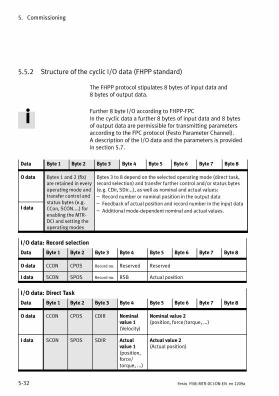
5. Commissioning
5-32 Festo P.BE-MTR-DCI-DN-EN en 1209a
5.5.2 Structure of the cyclic I/O data (FHPP standard)
The FHPP protocol stipulates 8 bytes of input data and8 bytes of output data.
Further 8 byte I/O according to FHPP-FPCIn the cyclic data a further 8 bytes of input data and 8 bytesof output data are permissible for transmitting parametersaccording to the FPC protocol (Festo Parameter Channel).A description of the I/O data and the parameters is providedin section 5.7.
Data Byte 1 Byte 2 Byte 3 Byte 4 Byte 5 Byte 6 Byte 7 Byte 8
O data Bytes 1 and 2 (fix)are retained in everyoperating mode andtransfer control andstatus bytes (e.g.CCon, SCON....) forenabling the MTR-DCI and setting theoperating modes
Bytes 3 to 8 depend on the selected operating mode (direct task,record selection) and transfer further control and/or status bytes(e.g. CDir, SDir...), as well as nominal and actual values:
– Record number or nominal position in the output data
– Feedback of actual position and record number in the input data
– Additional mode-dependent nominal and actual values.I data
I/O data: Record selection
Data Byte 1 Byte 2 Byte 3 Byte 4 Byte 5 Byte 6 Byte 7 Byte 8
O data CCON CPOS Record no. Reserved Reserved
I data SCON SPOS Record no. RSB Actual position
I/O data: Direct Task
Data Byte 1 Byte 2 Byte 3 Byte 4 Byte 5 Byte 6 Byte 7 Byte 8
O data CCON CPOS CDIR Nominalvalue 1(Velocity)
Nominal value 2(position, force/torque, ...)
I data SCON SPOS SDIR Actualvalue 1(position,force/torque, ...)
Actual value 2(Actual position)

5. Commissioning
5-33Festo P.BE-MTR-DCI-DN-EN en 1209a
Allocation of the control bytes (overview) 1)
CCON B7OPM2
B6OPM1
B5LOCK
B4–
B3RESET
B2BRAKE
B1STOP
B0ENABLE
Operating modeselection
MMIaccessBlocked
– Acknow-ledgefault
– Stop Enabledrive
CPOS B7–
B6CLEAR
B5TEACH
B4JOGN
B3JOGP
B2HOM
B1START
B0HALT
– Deleteremainingposition
Teachvalue
Jog nega-tive
Jog posi-tive
Starthoming
Startposi-tioningtask
Halt
CDIR
(directtaskonly)
B7FUNC
B6FAST
B5XLIM
B4VLIM
B3CONT
B2COM2
B1COM1
B0ABS
– – Deactivatestrokelimit
– – Control mode(position, force/torque, ...)
Absolute/Relative
1) – : Reserved
Allocation of the status bytes (overview) 1)
SCON B7OPM2
B6OPM1
B5LOCK
B424VL
B3FAULT
B2WARN
B1OPEN
B0ENABLED
Operating modeacknowledgement
FCT/HMIdevicecontrol
Loadvoltageapplied
Fault Warning Operationenabled
Driveenabled
SPOS B7REF
B6STILL
B5DEV
B4MOV
B3TEACH
B2MC
B1ACK
B0HALT
Drivehomed
Standstillmoni-toring
Followingerror
Axis ismoving
Acknow-ledgeteaching
Motioncomplete
Acknow-ledgestart
Halt
SDIR
(directtaskonly)
B7FUNC
B6FAST
B5XLIM
B4VLIM
B3CONT
B2COM2
B1COM1
B0ABS
– – Strokelimitreached
Speedlimitreached
– Control mode feed-back (position, force/torque, ...)
Absolute/Relative
1) – : reserved.

5. Commissioning
5-34 Festo P.BE-MTR-DCI-DN-EN en 1209a
5.5.3 Description of the I/O data (record selection)
Description of the O data: Record selection
Byte Bit EN Description
1 B0 ... B7 CCON Control bytes, see chapter 5.5.5
2 B0 ... B7 CPOS
3 B0 ... B7 Recordnumber
Pre-selection of record number for record selection (0...31)
4 B0 ... B7 – Reserved (= 0)
5 ... 8 B0...B31 – Reserved (= 0)
Description of the I data: Record selection
Byte Bit EN Description
1 B0 ... B7 SCON Status bytes, see chapter 5.5.6
2 B0 ... B7 SPOS
3 B0 ... B7 Recordnumber
Acknowledgement of record number for record selection(0...31)
4 B0 ... B7 Record statusbyte (RSB)
see SDIR for direct task, chapter 5.5.6
5 ... 8 B0 ... B31 Position, ... Acknowledgement of position for record selection:– Position in increments (32-bit number, Low byte first)

5. Commissioning
5-35Festo P.BE-MTR-DCI-DN-EN en 1209a
5.5.4 Description of the I/O data (direct task)
O data – Direct task
Byte Bit EN Description
1 B0 ... B7 CCON Control bytes, see chapter 5.5.5
2 B0 ... B7 CPOS
3 B0 ... B7 CDIR
4 B0 ... B7 Velocity Nominal value 1: preselection of velocity in % of the maximumvelocity
5 ... 8 B0...B31 PositionForce, ...
Nominal value 2: preselection depending on the controller modeof operation (see control byte 3 CDIR)– Positioning mode: position in increments– Force mode: force/torque in % of the rated current
O data – Direct task
Byte Bit EN Description
1 B0 ... B7 SCON Status bytes, see chapter 5.5.6
2 B0 ... B7 SPOS
3 B0 ... B7 SDIR
4 B0 ... B7 Velocity
Force/Torque
Actual value 1: acknowledgement depending on the controllermode of operation (see control byte 3 CDIR)– Positioning mode: preselection of speed in % of the
maximum speed– Force mode: force/torque in % of the rated current.
5 ... 8 B0...B31 Position Actual value 2: acknowledgement of position in increments

5. Commissioning
5-36 Festo P.BE-MTR-DCI-DN-EN en 1209a
5.5.5 Description of the control bytes CCON, CPOS, CDIR
CCON Control byte 1 (CCON) is used to control all states that mustbe available in all operating modes. The cooperation of thecontrol bits can be found under the description of the drivefunctions in section 5.6.
Control byte 1 (CCON)
Bit EN Description
B0ENABLE
Drive Enable = 1: Drive (controller) enabled= 0: Drive (controller) blocked
B1STOP
Stop 1 = 1: Operation enabled.Any existing faults will be deleted.
= 0: Stop 1 active (emergency ramp + cancel positioning task). The axisstops with maximum braking ramp; the positioning task is reset.
B2BRAKE
– Reserved: = 0
B3RESET
Reset Error With a rising edge a fault is acknowledged (reset) and the fault valuecleared.
B4–
– Reserved: = 0
B5LOCK
HMI accesslocked
Controls access to the diagnostic interface of the drive.= 1: HMI and FCT may only observe the drive, the device control (HMI
control) cannot be taken over by HMI and FCT.= 0: HMI or FCT may take control of the device (in order to modify para-
meters or to control inputs)
B6OPM1
Select Oper-atingMode
= 00: Record selection= 01: Direct task= 10: Reserved= 11: ReservedB7
OPM2
1) Switching between record selection and direct task is additionally permitted in the “Ready” state.

5. Commissioning
5-37Festo P.BE-MTR-DCI-DN-EN en 1209a
CPOS Control byte 2 (CPOS) controls the positioning sequences assoon as the drive is enabled.
Control byte 2 (CPOS) – Record selection and direct task
Bit EN Description
B0HALT
Halt = 1: “Halt” is not active.= 0: “Halt” activated (braking ramp + do not cancel positioning task).
The axis stops with a defined braking ramp; the positioning taskremains active (the remaining positioning can be deleted with B6).
B1START
Start Posi-tioning Task
The current nominal values will be transferred and positioning started(record 0 = homing) bymeans of a rising edge.
B2HOM
Start Homing Homing with the defined parameters is started by means of a risingedge.
B3JOGP
Jog positive The drive moves at the specified speed or rotational speed towardslarger actual values, while the bit is set. The movement begins with therising edge and ends with the falling edge.
B4JOGN
Jog negative The drive moves at the pre-set speed (rotation) towards lower actualvalues; see bit 3.
B5TEACH
Teach actualvalue
At a falling edge the current actual position is imported into the setpointregister of the current addressed positioning set; see section 5.6.3.The Teach target is defined with PNU 520.
B6CLEAR
Clearremainingpositioningpath
In the “Halt” state a rising edge causes the positioning task to becleared and a transition to the “Ready” state
B7–
– Reserved: =0

5. Commissioning
5-38 Festo P.BE-MTR-DCI-DN-EN en 1209a
CDIR Control byte CDIR is a special control byte for operating mode“Direct task”.
Control byte 3 (CDIR) – Direct task only
Bit EN Description
B0ABS
Absolute/Relative
= 0: Nominal value is absolute= 1: Nominal value is relative to last nominal value
B1COM1
ControlMode = 00: Positioning operation (see also 5.5.7 point 6)= 01: Force operation (see also 5.5.7 point 7)= 10: Reserved= 11: ReservedB2
COM2
B3CONT
– Reserved: = 0
B4VLIM
– Reserved: = 0
B5XLIM
Stroke (X-)limit not active
Force control:= 0: Stroke monitoring active= 1: Stroke monitoring not active
B6FAST
– Reserved: = 0
B7FUNC
– Reserved: = 0

5. Commissioning
5-39Festo P.BE-MTR-DCI-DN-EN en 1209a
5.5.6 Description of the status bytes SCON, SPOS, SDIR (RSB)
Status byte 1 (SCON)
Bit EN Description
B0ENABLED
Drive enabled = 0: Drive blocked, controller not active= 1: Drive (controller) enabled
B1OPEN
Operationenabled
= 0: Stop active= 1: Operation enabled, positioning possible
B2WARN
Warning = 0: Warning not present= 1: Warning present
B3FAULT
Fault = 0: No fault= 1: Fault present / fault response active.
Fault code in fault buffer
B424VL
Supply Voltageis Applied
= 0: No load voltage= 1: Load voltage applied
B5LOCK
Drive Controlby FCT/MMI
= 0: Device control by PLC/Fieldbus= 1: Device control by FCT/HMI
(PLC control is locked)
B6OPM1
Displayoperatingmode
= 00: Record selection (Standard)= 01: Direct task= 10: Reserved= 11: ReservedB7
OPM2

5. Commissioning
5-40 Festo P.BE-MTR-DCI-DN-EN en 1209a
Status byte 2 (SPOS)
Bit EN Description
B0HALT
Halt = 0: Halt is active= 1: Halt is not active, axis can be moved
B1ACK
Acknowledgestart
= 0: Ready for start (homing, jog)= 1: Start carried out (homing, jog)
B2MC
MotionComplete
= 0: Positioning task active= 1: Positioning task completed, possibly with faultNote: MC is first set after switching on (status “Drive blocked”).
B3TEACH
AcknowledgeTeaching
= 0: Ready for teaching= 1: Teaching carried out, actual value transferred
B4MOV
Axis ismoving = 0: Speed of the axis < limit value= 1: Speed of the axis >= limit value
B5DEV
Drag Error = 0: No following error= 1: Following error active
B6STILL
Standstillcontrol
= 0: After MC, axis remains in tolerance window= 1: After MC, axis is outside tolerance window
B7REF
Axis isreferenced
= 0: Homing must be carried out= 1: Home information exist, homing does not need to be carried out

5. Commissioning
5-41Festo P.BE-MTR-DCI-DN-EN en 1209a
Status byte 3 (SDIR) – Direct task
Bit EN Description
B0ABS
Absolute/Relative
= 0: Nominal value is absolute= 1: Nominal value is relative to last nominal value
B1COM1
COntrolModefeed back
= 00: Positioning mode= 01: Force mode= 10: Reserved= 11: ReservedB2
COM2
B3CONT
– Reserved
B4VLIM
Speed (V-)LIMit reached
Force mode:= 1: Speed limit reached= 0: Speed limit not reached
B5XLIM
Stroke (X-)LIMit reached
Force mode:= 1: Stroke limit value reached= 0: Stroke limit value not reached
B6FAST
– Reserved
B7FUNC
– Reserved
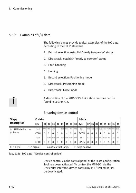
5. Commissioning
5-42 Festo P.BE-MTR-DCI-DN-EN en 1209a
5.5.7 Examples of I/O data
The following pages provide typical examples of the I/O dataaccording to the FHPP standard:
1. Record selection: establish “ready to operate” status
2. Direct task: establish “ready to operate” status
3. Fault handling
4. Homing
5. Record selection: Positioning mode
6. Direct task: Positioning mode
7. Direct task: Force mode
A description of the MTR-DCI's finite state machine can befound in section 5.8.
Ensuring device control
Step/Description
O data I data
Byte B7 B6 B5 B4 B3 B2 B1 B0 Byte B7 B6 B5 B4 B3 B2 B1 B0
0.1 HMI device con-trol = on
Byte 1 OPM2 OPM1 LOCK – RESET BRAKE STOP ENABL Byte 1 OPM2 OPM1 LOCK 24VL FAULT WARN OPEN ENABL
CCON 0 0 0 0 0 x 0 0 SCON 0 0 1 1 0 0 0 0
Byte 2 – CLEAR TEACH JOGN JOGP HOM START HALT Byte 2 REF STILL DEV MOV TEACH MC ACK HALT
CPOS 0 0 0 0 0 0 0 0 SPOS 0 0 0 0 0 1 0 0
0: 0 signal 1: 1 signal; x: not relevant (any); F: Edge positive
Tab. 5/8: I/O data: “Device control active”
Device control via the control panel or the Festo ConfigurationTool has been activated. To control the MTR-DCI via theDeviceNet interface, device control by FCT/HMI must firstbe deactivated.

5. Commissioning
5-43Festo P.BE-MTR-DCI-DN-EN en 1209a
1. Record selection: establish “ready to operate”status
1.1 Basic status of the drive when the supply voltage isswitched on. Step 1.2 or 1.3
1.2 Disable device control by FCT/HMI.Optionally, the takeover of device control by FCT/HMIcan be blocked with CCON.B5 = 1 (LOCK). Step 1.3
1.3 Enable drive (record selection) Homing: example 4, Tab. 5/12.
Step/Description
O data I data
Byte B7 B6 B5 B4 B3 B2 B1 B0 Byte B7 B6 B5 B4 B3 B2 B1 B0
1.1 Basic status
(HMI device control =off )
Byte 1 OPM2 OPM1 LOCK – RESET BRAKE STOP ENABL Byte 1 OPM2 OPM1 LOCK 24VL FAULT WARN OPEN ENABL
CCON 0 0 0 0 0 x 0 0 SCON 0 0 0 1 0 0 0 0
Byte 2 – CLEAR TEACH JOGN JOGP HOM START HALT Byte 2 REF STILL DEV MOV TEACH MC ACK HALT
CPOS 0 0 0 0 0 0 0 0 SPOS 0 0 0 0 0 1 0 0
1.2 Disable devicecontrol by FCT/HMI
Byte 1 OPM2 OPM1 LOCK – RESET BRAKE STOP ENABL Byte 1 OPM2 OPM1 LOCK 24VL FAULT WARN OPEN ENABL
CCON x x 1 0 x x x x SCON x x 0 x x x x x
Byte 2 – CLEAR TEACH JOGN JOGP HOM START HALT Byte 2 REF STILL DEV MOV TEACH MC ACK HALT
CPOS 0 x x x x x x x SPOS x x x x x x x x
1.3 Enable drive,enable operation
(Record Select)
Byte 1 OPM2 OPM1 LOCK – RESET BRAKE STOP ENABL Byte 1 OPM2 OPM1 LOCK 24VL FAULT WARN OPEN ENABL
CCON 0 0 x 0 0 x 1 1 SCON 0 0 0 1 0 0 1 1
Byte 2 – CLEAR TEACH JOGN JOGP HOM START HALT Byte 2 REF STILL DEV MOV TEACH MC ACK HALT
CPOS 0 0 0 0 0 0 0 1 SPOS 0 0 0 0 0 1 0 1
0: 0 signal 1: 1 signal; x: not relevant (any); F: Edge positive
Tab. 5/9: I/O data “Record selection: establish ready to operate status”
If there are faults after switching on or after setting CCON.B0(ENABLE): Fault handling: see example 3, Tab. 5/11.
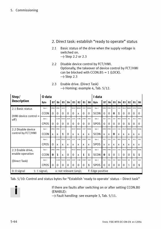
5. Commissioning
5-44 Festo P.BE-MTR-DCI-DN-EN en 1209a
2. Direct task: establish “ready to operate” status
2.1 Basic status of the drive when the supply voltage isswitched on. Step 2.2 or 2.3
2.2 Disable device control by FCT/HMI.Optionally, the takeover of device control by FCT/HMIcan be blocked with CCON.B5 = 1 (LOCK). Step 2.3
2.3 Enable drive. (Direct Task) Homing: example 4, Tab. 5/12.
Step/Description
O data I data
Byte B7 B6 B5 B4 B3 B2 B1 B0 Byte B7 B6 B5 B4 B3 B2 B1 B0
2.1 Basic status
(HMI device control =off )
Byte 1 OPM2 OPM1 LOCK – RESET BRAKE STOP ENABL Byte 1 OPM2 OPM1 LOCK 24VL FAULT WARN OPEN ENABL
CCON 0 0 0 0 0 x 0 0 SCON 0 0 0 1 0 0 0 0
Byte 2 – CLEAR TEACH JOGN JOGP HOM START HALT Byte 2 REF STILL DEV MOV TEACH MC ACK HALT
CPOS 0 0 0 0 0 0 0 0 SPOS 0 0 0 0 0 1 0 0
2.2 Disable devicecontrol by FCT/HMI
Byte 1 OPM2 OPM1 LOCK – RESET BRAKE STOP ENABL Byte 1 OPM2 OPM1 LOCK 24VL FAULT WARN OPEN ENABL
CCON x x 1 0 x x x x SCON x x 0 x x x x x
Byte 2 – CLEAR TEACH JOGN JOGP HOM START HALT Byte 2 REF STILL DEV MOV TEACH MC ACK HALT
CPOS 0 x x x x x x x SPOS x x x x x x x x
2.3 Enable drive,enable operation
(Direct Task)
Byte 1 OPM2 OPM1 LOCK – RESET BRAKE STOP ENABL Byte 1 OPM2 OPM1 LOCK 24VL FAULT WARN OPEN ENABL
CCON 0 1 x 0 0 x 1 1 SCON 0 1 0 1 0 0 1 1
Byte 2 – CLEAR TEACH JOGN JOGP HOM START HALT Byte 2 REF STILL DEV MOV TEACH MC ACK HALT
CPOS 0 0 0 0 0 0 0 1 SPOS 0 0 0 0 0 1 0 1
0: 0 signal 1: 1 signal; x: not relevant (any); F: Edge positive
Tab. 5/10: Control and status bytes for “Establish 'ready to operate' status – Direct task”
If there are faults after switching on or after setting CCON.B0(ENABLE): Fault handling: see example 3, Tab. 5/11.

5. Commissioning
5-45Festo P.BE-MTR-DCI-DN-EN en 1209a
3. Fault handling
For description of faults and warnings, see section 6.4.
3.1 A fault is shown with SCON.B3 (FAULT). Positioning can no longer be undertaken.
3.2 A warning is shown with SCON.B2 (WARN). Positioning is still possible.
3.3 Reset fault with positive edge on CCON.B3 (RESET). Fault bit SCON.B3 (FAULT) or SCON.B2 (WARN) isreset. SPOS.B2 (MC) is set Drive is ready for operation
3.4 Reset fault with negative edge on CCON.B0 (ENABLE). Fault bit SCON.B3 (FAULT) or SCON.B2 (WARN) isreset. SPOS.B2 (MC) is set Establish “ready to operate” status again(see examples 1, Tab. 5/9 and 2, Tab. 5/10)
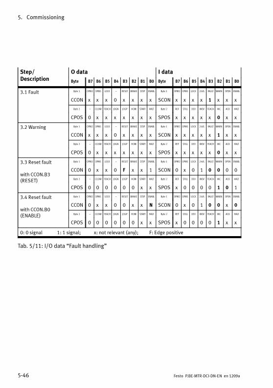
5. Commissioning
5-46 Festo P.BE-MTR-DCI-DN-EN en 1209a
Step/Description
O data I data
Byte B7 B6 B5 B4 B3 B2 B1 B0 Byte B7 B6 B5 B4 B3 B2 B1 B0
3.1 Fault Byte 1 OPM2 OPM1 LOCK – RESET BRAKE STOP ENABL Byte 1 OPM2 OPM1 LOCK 24VL FAULT WARN OPEN ENABL
CCON x x x 0 x x x x SCON x x x x 1 x x x
Byte 2 – CLEAR TEACH JOGN JOGP HOM START HALT Byte 2 REF STILL DEV MOV TEACH MC ACK HALT
CPOS 0 x x x x x x x SPOS x x x x x 0 x x
3.2 Warning Byte 1 OPM2 OPM1 LOCK – RESET BRAKE STOP ENABL Byte 1 OPM2 OPM1 LOCK 24VL FAULT WARN OPEN ENABL
CCON x x x 0 x x x x SCON x x x x x 1 x x
Byte 2 – CLEAR TEACH JOGN JOGP HOM START HALT Byte 2 REF STILL DEV MOV TEACH MC ACK HALT
CPOS 0 x x x x x x x SPOS x x x x x 0 x x
3.3 Reset fault
with CCON.B3(RESET)
Byte 1 OPM2 OPM1 LOCK – RESET BRAKE STOP ENABL Byte 1 OPM2 OPM1 LOCK 24VL FAULT WARN OPEN ENABL
CCON 0 x x 0 F x x 1 SCON 0 x 0 1 0 0 0 0
Byte 2 – CLEAR TEACH JOGN JOGP HOM START HALT Byte 2 REF STILL DEV MOV TEACH MC ACK HALT
CPOS 0 0 0 0 0 0 x x SPOS x 0 0 0 0 1 0 1
3.4 Reset fault
with CCON.B0(ENABLE)
Byte 1 OPM2 OPM1 LOCK – RESET BRAKE STOP ENABL Byte 1 OPM2 OPM1 LOCK 24VL FAULT WARN OPEN ENABL
CCON 0 x x 0 0 x x N SCON 0 x 0 1 0 0 x 0
Byte 2 – CLEAR TEACH JOGN JOGP HOM START HALT Byte 2 REF STILL DEV MOV TEACH MC ACK HALT
CPOS 0 0 0 0 0 0 x x SPOS x 0 0 0 0 1 x x
0: 0 signal 1: 1 signal; x: not relevant (any); F: Edge positive
Tab. 5/11: I/O data “Fault handling”

5. Commissioning
5-47Festo P.BE-MTR-DCI-DN-EN en 1209a
4. Homing (requires status 1.4 or 1.5)
4.1 A positive edge at CPOS.B2 (HOM, Start homing) startsthe homing run. The start is confirmed with SPOS.B1(Acknowledge start) as long as CPOS.B2 (HOM) is set.
4.2 Movement of the axis is shown with SPOS.B4 (MOV,Axis is moving).
4.3 After successful homing, SPOS.B2 (MC, MotionComplete) and SPOS.B7 (REF) are set.
Step/Description
O data I data
Byte B7 B6 B5 B4 B3 B2 B1 B0 Byte B7 B6 B5 B4 B3 B2 B1 B0
4.1 Start homing Byte 1 OPM2 OPM1 LOCK – RESET BRAKE STOP ENABL Byte 1 OPM2 OPM1 LOCK 24VL FAULT WARN OPEN ENABL
CCON 0 x x 0 0 x 1 1 SCON 0 x 0 1 0 0 1 1
Byte 2 – CLEAR TEACH JOGN JOGP HOM START HALT Byte 2 REF STILL DEV MOV TEACH MC ACK HALT
CPOS 0 0 0 0 0 F 0 1 SPOS 0 0 0 0 0 0 1 1
4.2 Homing is inprogress
Byte 1 OPM2 OPM1 LOCK – RESET BRAKE STOP ENABL Byte 1 OPM2 OPM1 LOCK 24VL FAULT WARN OPEN ENABL
CCON 0 x x 0 0 x 1 1 SCON 0 x 0 1 0 0 1 1
Byte 2 – CLEAR TEACH JOGN JOGP HOM START HALT Byte 2 REF STILL DEV MOV TEACH MC ACK HALT
CPOS 0 0 0 0 0 1 0 1 SPOS 0 0 0 1 0 0 1 1
4.3 Homing con-cluded
Byte 1 OPM2 OPM1 LOCK – RESET BRAKE STOP ENABL Byte 1 OPM2 OPM1 LOCK 24VL FAULT WARN OPEN ENABL
CCON 0 x x 0 0 x 1 1 SCON 0 x 0 1 0 0 1 1
Byte 2 – CLEAR TEACH JOGN JOGP HOM START HALT Byte 2 REF STILL DEV MOV TEACH MC ACK HALT
CPOS 0 0 0 0 0 0 0 1 SPOS 1 0 0 0 0 1 0 1
0: 0 signal 1: 1 signal; x: not relevant (any); F: Edge positive
Tab. 5/12: I/O data “Homing”
If there are faults during homing: Fault handling: see example 3, Tab. 5/11.

5. Commissioning
5-48 Festo P.BE-MTR-DCI-DN-EN en 1209a
5. Record selection: Positioning mode(requires status 1.3/2.3 and 4.)
Once “ready to operate” is established and homing has beencarried out, a positioning task can be started (sequencedepends on steps 5.1 .... 5.4):
5.1 Preselect record number: Byte 3 of the output data0 = Homing run1...31 = Programmable position set records
5.2 With CPOS.B1 (START, Start task) the preselectedpositioning task is started. The start is confirmed withSPOS.B1 (Acknowledge start) as long as CPOS.B1(START) is set.
5.3 Movement of the axis is shown with SPOS.B4 (MOV,Axis is moving).
5.4 On completion of the positioning task SPOS.B2 (MC,Motion Complete) is set.
If there are faults during positioning: Fault handling: see example 3, Tab. 5/11.

5. Commissioning
5-49Festo P.BE-MTR-DCI-DN-EN en 1209a
Step/Description
O data I data
Byte B7 B6 B5 B4 B3 B2 B1 B0 Byte B7 B6 B5 B4 B3 B2 B1 B0
5.1 Preselect recordnumber (Byte 3)
Byte 3 Record number Byte 3 Record number
Record
no.
Record no. (0...31) Record
no.
Previous record no. (0...31)
5.2 Start task Byte 1 OPM2 OPM1 LOCK – RESET BRAKE STOP ENABL Byte 1 OPM2 OPM1 LOCK 24VL FAULT WARN OPEN ENABL
CCON 0 0 x 0 0 x 1 1 SCON 0 0 0 1 0 0 1 1
Byte 2 – CLEAR TEACH JOGN JOGP HOM START HALT Byte 2 REF STILL DEV MOV TEACH MC ACK HALT
CPOS 0 0 0 0 0 0 F 1 SPOS 1 0 0 0 0 0 1 1
5.3 Positioning taskin progress
Byte 1 OPM2 OPM1 LOCK – RESET BRAKE STOP ENABL Byte 1 OPM2 OPM1 LOCK 24VL FAULT WARN OPEN ENABL
CCON 0 0 x 0 0 x 1 1 SCON 0 0 0 1 0 0 1 1
Byte 2 – CLEAR TEACH JOGN JOGP HOM START HALT Byte 2 REF STILL DEV MOV TEACH MC ACK HALT
CPOS 0 0 0 0 0 0 1 1 SPOS 1 0 0 1 0 0 1 1
Byte 3 Record number Byte 3 Record number
Record
no.
Record no. (0...31) Record
no.
Current record no. (0...31)
5.4 Positioning taskconcluded
Byte 1 OPM2 OPM1 LOCK – RESET BRAKE STOP ENABL Byte 1 OPM2 OPM1 LOCK 24VL FAULT WARN OPEN ENABL
CCON 0 0 x 0 0 x 1 1 SCON 0 0 0 1 0 0 1 1
Byte 2 – CLEAR TEACH JOGN JOGP HOM START HALT Byte 2 REF STILL DEV MOV TEACH MC ACK HALT
CPOS 0 0 0 0 0 0 0 1 SPOS 1 0 0 0 0 1 0 1
Byte 5...8 Reserved Byte 5...8 Position
– Reserved Actual
posi-
tion
Actual position (increments)
0: 0 signal 1: 1 signal; x: not relevant (any); F: Edge positive
Tab. 5/13: I/O data “Record selection: Positioning mode”

5. Commissioning
5-50 Festo P.BE-MTR-DCI-DN-EN en 1209a
6. Direct task: Positioning mode(requires status 1.3/2.3 and 4.)
Once “ready to operate” is established and homing has beencarried out, a nominal position must be preselected(sequence depends on steps 6.1 ... 6.4)
6.1 The nominal position is transferred in increments inbytes 5...8 of the output word.The nominal speed is transferred in % in byte 3(0 = no speed; 100 = max. speed).
6.2 With CPOS.B1 (START, Start positioning task) thepreselected positioning task is started. The start isconfirmed with SPOS.B1 (Acknowledge start) as long asCPOS.B1 (START) is set.
6.3 Movement of the axis is shown with SPOS.B4 (MOV,Axis is moving).
6.4 At the end of the positioning task, SPOS.B2 (MC,Motion Complete) is set.
If there are faults during positioning: Fault handling: see example 3, Tab. 5/11.

5. Commissioning
5-51Festo P.BE-MTR-DCI-DN-EN en 1209a
Step/Description
O data I data
Byte B7 B6 B5 B4 B3 B2 B1 B0 Byte B7 B6 B5 B4 B3 B2 B1 B0
6.1 Preselect positionand speed(bytes 4 and 5...8)
Byte 4 Velocity Byte 4 Velocity
Speed Speed preselection(0...100 %)
Speed Speed response message(0...100 %)
Byte 5...8 Position Byte 5...8 Position
Nom-
inal
posi-
tion
Nominal position(increments),
see section 5.5.2
Actual
posi-
tion
Actual position (increments),see section 5.5.2
6.2 Start task Byte 1 OPM2 OPM1 LOCK – RESET BRAKE STOP ENABL Byte 1 OPM2 OPM1 LOCK 24VL FAULT WARN OPEN ENABL
CCON 0 1 x 0 0 x 1 1 SCON 0 1 0 1 0 0 1 1
Byte 2 – CLEAR TEACH JOGN JOGP HOM START HALT Byte 2 REF STILL DEV MOV TEACH MC ACK HALT
CPOS 0 0 0 0 0 0 F 1 SPOS 1 0 0 0 0 0 1 1
Byte 3 FUNC FAST XLIM VLIM CONT COM2 COM1 ABS Byte 3 FUNC FAST XLIM VLIM CONT COM2 COM1 ABS
CDIR 0 0 0 0 0 0 0 S SDIR 0 0 0 0 0 0 0 S
6.3. Positioning taskin progress
Byte 1 OPM2 OPM1 LOCK – RESET BRAKE STOP ENABL Byte 1 OPM2 OPM1 LOCK 24VL FAULT WARN OPEN ENABL
CCON 0 1 x 0 0 x 1 1 SCON 0 1 0 1 0 0 1 1
Byte 2 – CLEAR TEACH JOGN JOGP HOM START HALT Byte 2 REF STILL DEV MOV TEACH MC ACK HALT
CPOS 0 0 0 0 0 0 1 1 SPOS 1 0 0 1 0 0 1 1
6.4 Positioning taskconcluded
Byte 1 OPM2 OPM1 LOCK – RESET BRAKE STOP ENABL Byte 1 OPM2 OPM1 LOCK 24VL FAULT WARN OPEN ENABL
CCON 0 1 x 0 0 x 1 1 SCON 0 1 0 1 0 0 1 1
Byte 2 – CLEAR TEACH JOGN JOGP HOM START HALT Byte 2 REF STILL DEV MOV TEACH MC ACK HALT
CPOS 0 0 0 0 0 0 0 1 SPOS 1 0 0 0 0 1 0 1
0: 0 signal 1: 1 signal; x: not relevant (any); F: Edge positiveS: Positioning condition: 0= absolute; 1 = relative
Tab. 5/14: I/O data “Direct task: Positioning mode”

5. Commissioning
5-52 Festo P.BE-MTR-DCI-DN-EN en 1209a
7. Direct task: Force mode(requires status 1.3/2.3 and 4)
Once “ready to operate” is established and homing has beencarried out, a nominal value must be specified and thesystem must be prepared for operation in Force mode.
7.1 Specify the nominal value in % of nominal motorcurrent. (Take account of friction influences of theconnected axis).
7.2 Prepare Force mode: set bit CDIR.B1 COM1, and set bitCDIR.B5 XLIM depending on the desired level of strokelimitation.
7.3 Start the positioning task with CPOS.B1 START. Thestart is confirmed with SPOS.B1 (Acknowledge start) aslong as CPOS.B1 (START) is set.
7.4 or 7.5The corresponding status bits are set depending onwhether or not the nominal value is reached.
7.6 The positioning task is ended automatically when thestroke limit or software end position is reached. Thesystem switches back to position control.
7.7 The positioning task can be stopped from the controller,e. g. by means of STOP.
NoteIn Force mode, the nominal value can only be changedafter the last specification is reached (MC), by means of anew start pulse edge.
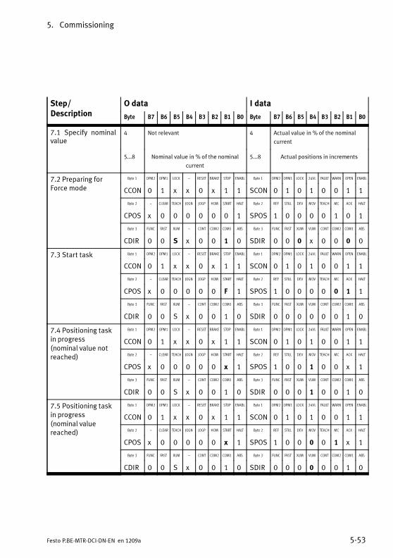
5. Commissioning
5-53Festo P.BE-MTR-DCI-DN-EN en 1209a
Step/Description
O data I data
Byte B7 B6 B5 B4 B3 B2 B1 B0 Byte B7 B6 B5 B4 B3 B2 B1 B0
7.1 Specify nominalvalue
4 Not relevant 4 Actual value in % of the nominal
current
5...8 Nominal value in % of the nominal
current
5...8 Actual positions in increments
7.2 Preparing forForce mode
Byte 1 OPM2 OPM1 LOCK – RESET BRAKE STOP ENABL Byte 1 OPM2 OPM1 LOCK 24VL FAULT WARN OPEN ENABL
CCON 0 1 x x 0 x 1 1 SCON 0 1 0 1 0 0 1 1
Byte 2 – CLEAR TEACH JOGN JOGP HOM START HALT Byte 2 REF STILL DEV MOV TEACH MC ACK HALT
CPOS x 0 0 0 0 0 0 1 SPOS 1 0 0 0 0 1 0 1
Byte 3 FUNC FAST XUM – CONT COM2 COM1 ABS Byte 3 FUNC FAST XUM VUM CONT COM2 COM1 ABS
CDIR 0 0 S x 0 0 1 0 SDIR 0 0 0 x 0 0 0 0
7.3 Start task Byte 1 OPM2 OPM1 LOCK – RESET BRAKE STOP ENABL Byte 1 OPM2 OPM1 LOCK 24VL FAULT WARN OPEN ENABL
CCON 0 1 x x 0 x 1 1 SCON 0 1 0 1 0 0 1 1
Byte 2 – CLEAR TEACH JOGN JOGP HOM START HALT Byte 2 REF STILL DEV MOV TEACH MC ACK HALT
CPOS x 0 0 0 0 0 F 1 SPOS 1 0 0 0 0 0 1 1
Byte 3 FUNC FAST XUM – CONT COM2 COM1 ABS Byte 3 FUNC FAST XUM VUM CONT COM2 COM1 ABS
CDIR 0 0 S x 0 0 1 0 SDIR 0 0 0 0 0 0 1 0
7.4 Positioning taskin progress(nominal value notreached)
Byte 1 OPM2 OPM1 LOCK – RESET BRAKE STOP ENABL Byte 1 OPM2 OPM1 LOCK 24VL FAULT WARN OPEN ENABL
CCON 0 1 x x 0 x 1 1 SCON 0 1 0 1 0 0 1 1
Byte 2 – CLEAR TEACH JOGN JOGP HOM START HALT Byte 2 REF STILL DEV MOV TEACH MC ACK HALT
CPOS x 0 0 0 0 0 x 1 SPOS 1 0 0 1 0 0 x 1
Byte 3 FUNC FAST XUM – CONT COM2 COM1 ABS Byte 3 FUNC FAST XUM VUM CONT COM2 COM1 ABS
CDIR 0 0 S x 0 0 1 0 SDIR 0 0 0 1 0 0 1 0
7.5 Positioning taskin progress(nominal valuereached)
Byte 1 OPM2 OPM1 LOCK – RESET BRAKE STOP ENABL Byte 1 OPM2 OPM1 LOCK 24VL FAULT WARN OPEN ENABL
CCON 0 1 x x 0 x 1 1 SCON 0 1 0 1 0 0 1 1
Byte 2 – CLEAR TEACH JOGN JOGP HOM START HALT Byte 2 REF STILL DEV MOV TEACH MC ACK HALT
CPOS x 0 0 0 0 0 x 1 SPOS 1 0 0 0 0 1 x 1
Byte 3 FUNC FAST XUM – CONT COM2 COM1 ABS Byte 3 FUNC FAST XUM VUM CONT COM2 COM1 ABS
CDIR 0 0 S x 0 0 1 0 SDIR 0 0 0 0 0 0 1 0

5. Commissioning
5-54 Festo P.BE-MTR-DCI-DN-EN en 1209a
Step/Description
I dataO dataStep/Description B0B1B2B3B4B5B6B7ByteB0B1B2B3B4B5B6B7Byte
7.6 Positioning taskinterrupted (strokelimit or software endposition reached)
Byte 1 OPM2 OPM1 LOCK – RESET BRAKE STOP ENABL Byte 1 OPM2 OPM1 LOCK 24VL FAULT WARN OPEN ENABL
CCON 0 1 x x 0 x 1 1 SCON 0 1 0 1 0 0 1 1
Byte 2 – CLEAR TEACH JOGN JOGP HOM START HALT Byte 2 REF STILL DEV MOV TEACH MC ACK HALT
CPOS x 0 0 0 0 0 x 1 SPOS 1 0 0 0 0 1 x 1
Byte 3 FUNC FAST XUM – CONT COM2 COM1 ABS Byte 3 FUNC FAST XUM VUM CONT COM2 COM1 ABS
CDIR 0 0 S x 0 0 1 0 SDIR 0 0 1 0 0 0 0 0
7.7 End positioningtask (e. g. with STOP)
Byte 1 OPM2 OPM1 LOCK – RESET BRAKE STOP ENABL Byte 1 OPM2 OPM1 LOCK 24VL FAULT WARN OPEN ENABL
CCON 0 1 x x 0 x 0 1 SCON 0 1 0 1 0 0 0 1
Byte 2 – CLEAR TEACH JOGN JOGP HOM START HALT Byte 2 REF STILL DEV MOV TEACH MC ACK HALT
CPOS x 0 0 0 0 0 x 1 SPOS 1 0 0 0 0 1 x 1
Byte 3 FUNC FAST XUM – CONT COM2 COM1 ABS Byte 3 FUNC FAST XUM VUM CONT COM2 COM1 ABS
CDIR 0 0 S x 0 0 1 0 SDIR 0 0 0 0 0 0 0 0
0: 0 signal 1: 1 signal; x: not relevant (any); F: Edge positiveS: Path limitation (stroke limit): 0 = stroke limit active, 1 = stroke limit not active
Tab. 5/15: I/O data Direct task: Force mode
If there are faults during Force mode:see example 3, table 5/13 Fault handling.

5. Commissioning
5-55Festo P.BE-MTR-DCI-DN-EN en 1209a
5.6 Sequence control according to the FHPP standard
5.6.1 Homing
Information on homing, reference coordinates, working area,and calculation rules for the reference system are provided inchapter 1.6
After switching on, homing must be carried out before a posi-tioning task can be executed (see parameter “HomingRequired”: FHPP PNU 1014 /CI 23F6h)
The drive homes to a stop or a reference switch. An increasein the motor current with the drive shaft motionless indicatesthat a stop has been reached. Since the drive must not per-manently rest at the stop, it must move a minimum of0.25 mm back into the stroke range (axis zero point offset).
Sequence:
1. Searching for the reference point in accordance with theconfigured method.
2. Moving from the reference point to the axis zero point(according to axis zero point offset AZ)
3. Setting at axis zero point:Current position = 0 – project zero point offset PZ

5. Commissioning
5-56 Festo P.BE-MTR-DCI-DN-EN en 1209a
Overview of parameters involved (see also section B.2.15)
Parameters involved Description FCT PNU CI
Axis zero point offset x 1010 607Ch
Homing method x 1011 6098h
Homing speeds x 1012 6099h
Homing required – 1014 23F6h
Maximum homing torque x 1015 23F7h
Start (FHPP) CPOS.B2 = positive edge: Start homing
Feedback (FHPP) SPOS.B1 = positive edge: Acknowledge startSPOS.B7 = drive homed to reference point
Requirement Device control by PLC/FieldbusController must be in status “Operation enabled”No active command for jogging
Tab. 5/16: Parameters involved in homing
Homing methods 1)
hex dec Description
17h 23 Search for reference switch in positive direction.
1Bh 27 Search for reference switch in negative direction.
EFh -17 Search for negative stop. The point found is the reference position. As theaxis must not stand still at the stop, the axis zero point offset must be ≠ 0.
EEh -18 Search for positive stop. The point found is the reference position. As theaxis must not stand still at the stop, the axis zero point offset must be ≠ 0.
1) For a detailed description of homing methods see section 1.6.3
Tab. 5/17: Overview of homing methods

5. Commissioning
5-57Festo P.BE-MTR-DCI-DN-EN en 1209a
5.6.2 Jog mode
In the “Operation enabled” state the drive can be moved byleft/right jogging. This function is usually used for
– Approaching teach positions.
– Moving the drive out of the way (e.g. after a plant mal-function).
– Manual positioning as normal mode (manual feed).
Sequence
1. When one of the signals “Jog left / Jog right” is set, thedrive starts to move slowly. Due to the slow speed, a posi-tion can be defined very accurately.
2. If the signal remains set for longer than the configured“Phase 1 duration”, the speed is increased until the confi-gured maximum speed is reached. This enables largestrokes to be covered rapidly.
3. If the signal changes to 0, the drive is braked with thepre-set maximum deceleration.
4. If the drive reaches a software end position, it will stopautomatically. The software end position is not exceeded;the distance for stopping is accounted for according tothe defined ramp. Here too, the system does not leaveJogging mode until Jogging = 0.

5. Commissioning
5-58 Festo P.BE-MTR-DCI-DN-EN en 1209a
1 Low speed phase 1(slow travel)
2 Maximum speed forphase 2
3 Acceleration /deceleration
4 Duration of phase 1 CPOS.B3 orCPOS.B4(joggingpositive/negative)
Speed v (t)
t [s]
1
0
1
23
4
3
Fig. 5/2: Flow diagram for jogging mode
Overview of parameters involved (see section B.2.9)
Parameters involved Description FCT PNU CI
Speed of phase 2 in (inc/s) x 531 20ED/21
Acceleration or deceleration (Inc/s2) x 532 20EE/21
Duration of phase 1 in ms x 534 20E9/21
Start (FHPP) CPOS.B3 = positive edge: jogging positive (forwards)CPOS.B4 = positive edge: jogging negative (backwards)
Feedback (FHPP) SPOS.B4 = 1: Drive is movingSPOS.B2 = 0: (Motion Complete)
Requirement Device control by PLC/FieldbusController must be in status “Operation enabled”
Tab. 5/18: Parameters involved in jogging mode

5. Commissioning
5-59Festo P.BE-MTR-DCI-DN-EN en 1209a
5.6.3 Teaching via Fieldbus
Position values can be taught via the Fieldbus. Previouslytaught position values will then be overwritten.
Sequence
1. The drive is brought to the desired position either by jogmode or manually.
2. The user must make sure that the desired parameter isselected. To do this, the “Teach target” parameter and,where appropriate, the correct record address must bewritten.
Teach target(PNU 520)
For teaching
= 1 (default) Nominal position in the position setrecord.
– Record selection:Position set record aftercontrol byte 3
– Direct task:Position set record after PNU=400
= 2 Axis zero point
= 3 Project zero point
= 4 Lower software end position
= 5 Upper software end position
Tab. 5/19: Overview of teach targets
3. Teaching takes place via the handshake of the bits in thecontrol and status bytes CPOS/SPOS:

5. Commissioning
5-60 Festo P.BE-MTR-DCI-DN-EN en 1209a
1 Ready for teaching
2 Value transferred
1
0
ResetSPOS.B3
Teach valueCPOS.B5
1 2
1
0
Fig. 5/3: Handshake when teaching
Note:The drive does not need to stop moving for teaching. How-ever, a speed of 1 m/s means that the actual positionchanges by 1 mm every millisecond. With the usual cycletimes of PLC + Fieldbus + motor controller, there will still beinaccuracies of several millimetres even at a speed of only100 mm/s.
Overview of parameters involved (see sections B.2.8 and B.2.9)
Parameters involved Description FCT PNU CI
Teach target – 1) 520 21FEh
Record number – 1) 400 2190h
Start (FHPP) CPOS.B5 = Falling edge: Teach value
Acknowledgement(FHPP)
SPOS.B3 = 1: Value transferred
Requirement Device control by PLC/FieldbusController must be in status “Operation enabled”
1) Teaching is made possible in the Festo Configuration Tool by special functions.
Tab. 5/20: Parameters involved in teaching

5. Commissioning
5-61Festo P.BE-MTR-DCI-DN-EN en 1209a
5.6.4 Record selection (Positioning mode)
A positioning task in record selection mode is described by arecord of nominal values.
In the “operation enabled” state, a record can be started viathe record number. This function is usually used for:
– Moving to any position in the record list by the PLC
– Processing a positioning profile by linking records
– Known target positions that seldom change (change offormula).
Sequence
1. Set the desired set number in the master's output data.Up till the start, the controller continues to respond withthe number of the record last executed.
2. With a rising edge at START (CPOS.B1) the controlleraccepts the record number and starts the positioningtask.
3. The controller signals with the rising edge on Acknow-ledge Start that the PLC output data have been acceptedand that the positioning task is now active. The posi-tioning command is executed regardless of whether Start(CPOS.B1) has been reset to zero or not.
4. When the record is concluded, MC (SPOS.B2) is set.

5. Commissioning
5-62 Festo P.BE-MTR-DCI-DN-EN en 1209a
Possible causes of faults:
– No homing performed.
– The target position and/or the preselect position cannotbe reached.
– Invalid record number.
– Uninitialised record.
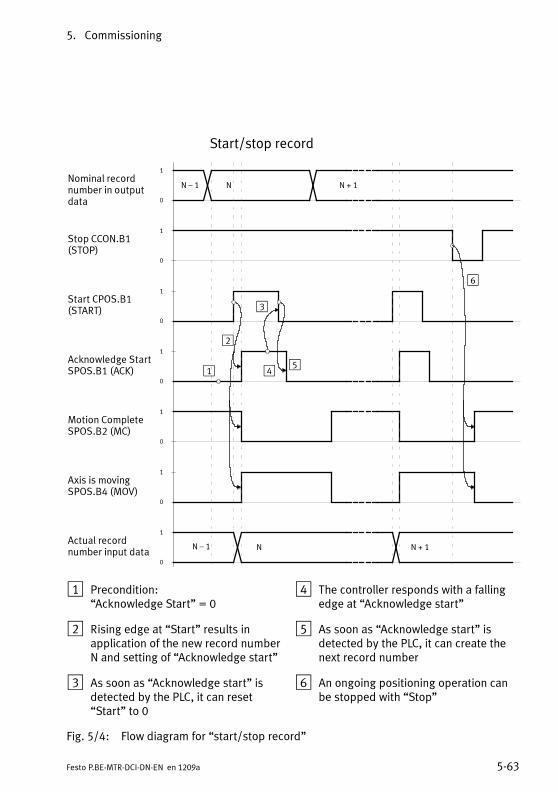
5. Commissioning
5-63Festo P.BE-MTR-DCI-DN-EN en 1209a
Start/stop record
Nominal recordnumber in outputdata
Stop CCON.B1(STOP)
Acknowledge StartSPOS.B1 (ACK)
Motion CompleteSPOS.B2 (MC)
Actual recordnumber input data
N – 1 N N + 1
N – 1 N
1
0
1
0
1
0
1
0
1
0
1
2
3
4
6
1
0
1
0
Axis is movingSPOS.B4 (MOV)
Start CPOS.B1(START)
N + 1
5
1 Precondition:“Acknowledge Start” = 0
2 Rising edge at “Start” results inapplication of the new record numberN and setting of “Acknowledge start”
3 As soon as “Acknowledge start” isdetected by the PLC, it can reset“Start” to 0
4 The controller responds with a fallingedge at “Acknowledge start”
5 As soon as “Acknowledge start” isdetected by the PLC, it can create thenext record number
6 An ongoing positioning operation canbe stopped with “Stop”
Fig. 5/4: Flow diagram for “start/stop record”
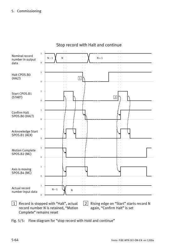
5. Commissioning
5-64 Festo P.BE-MTR-DCI-DN-EN en 1209a
Stop record with Halt and continue
Nominal recordnumber in outputdata
Acknowledge StartSPOS.B1 (ACK)
Motion CompleteSPOS.B2 (MC)
Actual recordnumber input data
N – 1 N N + 1
N – 1 N
1
0
1
0
1
0
1
0
1
0
1
0
Axis is movingSPOS.B4 (MC)
Halt CPOS.B0(HALT)
1
0
Start CPOS.B1(START)
1
0
Confirm HaltSPOS.B0 (HALT)
1
2
1 Record is stopped with “Halt”, actualrecord number N is retained, “MotionComplete” remains reset
2 Rising edge on “Start” starts record Nagain, “Confirm Halt” is set
Fig. 5/5: Flow diagram for “stop record with Hold and continue”
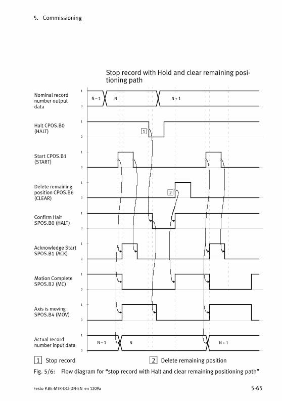
5. Commissioning
5-65Festo P.BE-MTR-DCI-DN-EN en 1209a
Stop record with Hold and clear remaining posi-tioning path
Nominal recordnumber outputdata
Acknowledge StartSPOS.B1 (ACK)
Motion CompleteSPOS.B2 (MC)
Actual recordnumber input data
N – 1 N N + 1
N – 1 N
1
0
1
0
1
0
1
0
1
0
1
0
Axis is movingSPOS.B4 (MOV)
Halt CPOS.B0(HALT)
N + 1
1
0
Start CPOS.B1(START)
Delete remainingposition CPOS.B6(CLEAR)
1
0
1
0
Confirm HaltSPOS.B0 (HALT)
1
2
1 Stop record 2 Delete remaining position
Fig. 5/6: Flow diagram for “stop record with Halt and clear remaining positioning path”

5. Commissioning
5-66 Festo P.BE-MTR-DCI-DN-EN en 1209a
Parameters involved (Record structure)
The entries in the position set table can be written via theFieldbus (see Tab. 5/21). Each individual nominal value isaddressed via a dedicated PNU. A record consists of the nom-inal values with the same subindex.
The composition of the position set table as per FHPP isdescribed in appendix B.2.8.
Overview of parameters involved (see section B.2.8)
Record structure Description FCT PNU CI
Absolute/relative positioning x 401 20E0/01h
Target position x 404 20E0/02h
Speed x 406 20E0/03h
Acceleration x 407 20E0/04h
Start CPOS.B1 = positive edge: StartJogging and homing have priority.
Feedback SPOS.B2 = 0: Motion completeSPOS.B1 = positive edge: Acknowledge startSPOS.B4 = 1: Drive is moving
Requirements Device control by PLC/Fieldbus.Controller must be in “Operation enabled” status.A valid record number is active
Tab. 5/21: Parameters involved in record selection

5. Commissioning
5-67Festo P.BE-MTR-DCI-DN-EN en 1209a
5.6.5 Direct task (Positioning mode, Force mode)
In the “operation enabled” state (direct mode) a positioningtask is formulated directly in the I/O data transmitted overthe Fieldbus. The position nominal values for positioning orforce mode are stored in the PLC.
A positioning profile based on sequencing of records can beimplemented by means of external control by the master.
Positioning mode
The positioning mode is used in the following situations:
– Moving to any position within the effective stroke.
– The target positions are unknown during planning orchange frequently (several different workpiece positions).
Sequence
1. The user configures the desired nominal value (position)and the positioning condition (absolute/relative) inhis/her output data.
2. With a rising edge on START (CPOS.B1), the controlleraccepts the nominal position and starts the positioningtask.
3. After the start you must wait for MC before a new startcan be made.
4. When the nominal position is reached, MC (SPOS.B2) isset.

5. Commissioning
5-68 Festo P.BE-MTR-DCI-DN-EN en 1209a
Starting the positioning task
Nominal positionoutput data
StartCPOS.B1
Acknowledge StartSPOS.B1
Motion CompleteSPOS.B2
N - 1 N N + 1
1
0
1
0
1
0
1
0
N + 2
Fig. 5/7: Starting the positioning task
The sequence of the remaining control and status bits as wellas the functions Halt and Stop react in the same way as theRecord Select function; see Fig. 5/4, Fig. 5/5 and Fig. 5/6.
Possible causes of faults:
– Homing not carried out.
– Target position cannot be reached or lies outside the soft-ware end positions.
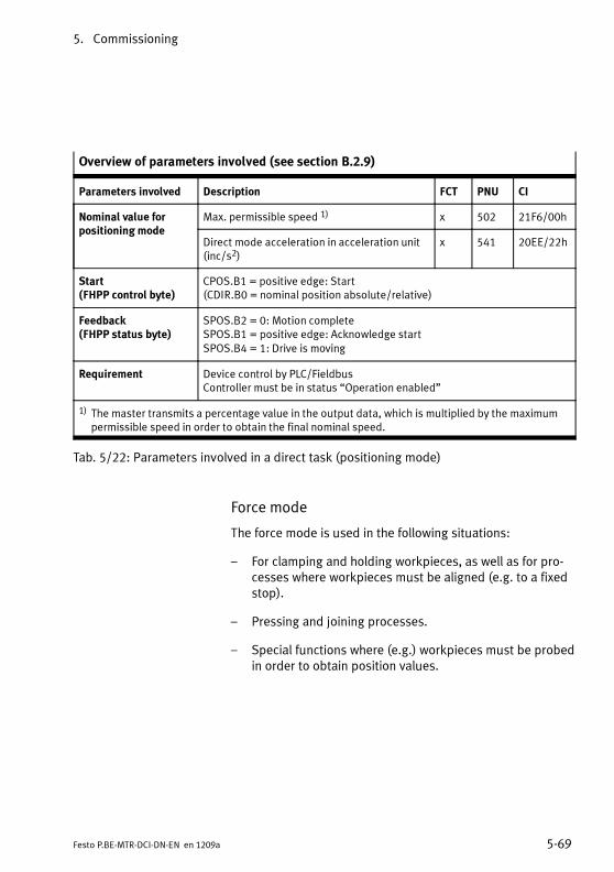
5. Commissioning
5-69Festo P.BE-MTR-DCI-DN-EN en 1209a
Overview of parameters involved (see section B.2.9)
Parameters involved Description FCT PNU CI
Nominal value forpositioning mode
Max. permissible speed 1) x 502 21F6/00h
Direct mode acceleration in acceleration unit(inc/s2)
x 541 20EE/22h
Start(FHPP control byte)
CPOS.B1 = positive edge: Start(CDIR.B0 = nominal position absolute/relative)
Feedback(FHPP status byte)
SPOS.B2 = 0: Motion completeSPOS.B1 = positive edge: Acknowledge startSPOS.B4 = 1: Drive is moving
Requirement Device control by PLC/FieldbusController must be in status “Operation enabled”
1) The master transmits a percentage value in the output data, which is multiplied by the maximumpermissible speed in order to obtain the final nominal speed.
Tab. 5/22: Parameters involved in a direct task (positioning mode)
Force mode
The force mode is used in the following situations:
– For clamping and holding workpieces, as well as for pro-cesses where workpieces must be aligned (e.g. to a fixedstop).
– Pressing and joining processes.
– Special functions where (e.g.) workpieces must be probedin order to obtain position values.
5. Commissioning
5-70 Festo P.BE-MTR-DCI-DN-EN en 1209a
Note on Force modeThe motor torque is controlled indirectly via the regulationof the current. All specification for forces/torques aredefined in relation to the nominal motor torque (relative tothe nominal motor current). The actual force on the axisshould be determined/checked during commissioningusing external measuring devices and adjusted.
NoteThe following settings are necessary for parameterising theforce mode (see Tab. 5/23)
– Force window (permissible deviation from the nominalvalue obtained via Fieldbus).
– Speed limiting (the maximum speed that the driveshould reach. Without this specification, the drive wouldaccelerate unbraked if it encounters no opposing force(e.g. missing workpiece).
– Damping time (the time that the nominal force must beapplied before the “Motion complete” message is gener-ated).
• Extend the damping time if the nominal force is alreadyreached on startup (before reaching the workpiece) dueto the increased startup toque.
Force mode is prepared by switching the control mode. Thedrive remains stationary in a controlled position.

5. Commissioning
5-71Festo P.BE-MTR-DCI-DN-EN en 1209a
Sequence
1. The user specifies the desired nominal value (in % of therated motor torque) and the speed limit in his/her outputdata.
2. With a rising edge on Start (CPOS.B1) the controlleraccepts the nominal torque and begins applying force/torque in the direction indicated by the nominal value'ssign.
– Once this speed has been reached, the “Speed limitreached” bit is set in the (status byte SDIR).
– Once the nominal value has been reached, taking intoaccount the target window and the time window, the“MC” signal is set. The motor current continues to becontrolled.
– In the case of resistance, e.g. from a workpiece in thetraversing range, the drive pushes against theobstruction with a defined force (see Fig. 5/8).
– If the distance set in path/stroke monitoring (relativeto the start position) is exceeded, the bit “Stroke limitreached” is set in the status byte SDIR. The drive isbraked with the emergency-stop ramp, is then held ina controlled position (the current position), and theMC signal is set.
Possible causes of faults:
– Homing not carried out.
– Axis is at the SW end position when the positioning taskstarts.

5. Commissioning
5-72 Festo P.BE-MTR-DCI-DN-EN en 1209a
Overview of parameters involved (see section B.2.9)
Parameter Description FCT PNU CI
Force mode 1) Stroke limitation x 510 60F6/01h
Minimum torque x 511 60F6/05h
Maximum torque x 512 6072h
Force target window (tolerance) x 552 60F6/03h
Damping time in [ms] x 553 60F6/04h
Max. permitted speed x 554 60F6/02h
Start CPOS.B1 = positive edge(CDIR.B0 = nominal position absolute/relative)
Feedback SPOS.B2 = 0: Motion completeSPOS.B1 = positive edge: Acknowledge startSPOS.B4 = 1: Drive is moving
Requirement Device control by PLC/FieldbusController must be in status “Operation enabled”
1) Other parameters:6071h Target torque 6076h Rated torque (nominal torque)6077h Actual torque 6087h Torque slope (torque ramp)6088h Torque profile type CDIR.B5 Stroke limitation active/inactive
Tab. 5/23: Parameters involved in a direct task (force mode)

5. Commissioning
5-73Festo P.BE-MTR-DCI-DN-EN en 1209a
Starting the positioning task / Force mode
Nominal torquespeed limitingoutput data
Start CPOS.B1
Acknowledge StartSPOS.B1 (ACK)
Motion CompleteSPOS.B2 (MC)
N – 1 N N + 1
1
0
1
0
1
0
1
0
1
0
Axis is movingSPOS.B4 (MOV)
1
2 3 4
1 Nominal torque / force reached 2 Axis is pressing against resistance
3 Resistance removed / overcome 4 SW end position / stroke limit reached
Fig. 5/8: Starting the positioning task / Force mode
The signal “MC” (Motion Complete) is used in this controlmode to mean “nominal value/stroke limit reached”. Thesequence of the remaining control and status bits as well asthe functions Halt and Stop react in the same way as theRecord Select function; see Fig. 5/4, Fig. 5/5 and Fig. 5/6.
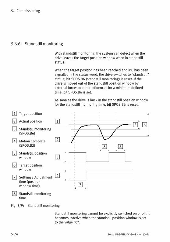
5. Commissioning
5-74 Festo P.BE-MTR-DCI-DN-EN en 1209a
5.6.6 Standstill monitoring
With standstill monitoring, the system can detect when thedrive leaves the target position window when in standstillstatus.
When the target position has been reached and MC has beensignalled in the status word, the drive switches to “standstill”status; bit SPOS.B6 (standstill monitoring) is reset. If thedrive is moved out of the standstill position window byexternal forces or other influences for a minimum definedtime, bit SPOS.B6 is set.
As soon as the drive is back in the standstill position windowfor the standstill monitoring time, bit SPOS.B6 is reset.
1 Target position
2 Actual position
3 Standstill monitoring(SPOS.B6)
4 Motion Complete(SPOS.B2)
5 Standstill positionwindow
6 Target positionwindow
7 Settling / Adjustmenttime (positionwindow time)
8 Standstill monitoringtime
1
0
1
0
1
2
3
4
5 6
7
88
Fig. 5/9: Standstill monitoring
Standstill monitoring cannot be explicitly switched on or off. Itbecomes inactive when the standstill position window is setto the value “0”.

5. Commissioning
5-75Festo P.BE-MTR-DCI-DN-EN en 1209a
Overview of parameters involved (see section B.2.15)
Parameters involved Description FCT PNU CI
Nominal position – 1040 6062h
Current position – 1041 6064h
Standstill position window – 1042 2040h
Standstill monitoring time – 1043 2041h
Start (FHPP) SPOS.B2 = positive edge: Motion complete
Feedback (FHPP) SPOS.B6 = 1: Drive has moved out of standstill position window
Requirement Device control by PLC/FieldbusController in “Operation enabled” state
Tab. 5/24: Parameters involved in standstill monitoring
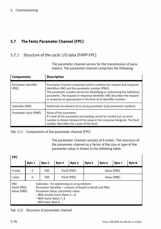
5. Commissioning
5-76 Festo P.BE-MTR-DCI-DN-EN en 1209a
5.7 The Festo Parameter Channel (FPC)
5.7.1 Structure of the cyclic I/O data (FHPP-FPC)
The parameter channel serves for the transmission of para-meters. The parameter channel comprises the following:
Components Description
Parameter identifier(PKE)
Parameter channel component which contains the request and responseidentifiers (AK) and the parameter number (PNU).The parameter number serves for identifying or addressing the individualparameter. The request or response identifier (AK) describes the requestor response as appropriate in the form of an identifier number.
Subindex (IND) Addresses an element of an array parameter (sub-parameter number).
Parameter value (PWE) Value of the parameter.If a task of the parameter processing cannot be carried out, an errornumber is shown instead of the value in the response telegram. The faultnumber describes the cause of the fault.
Tab. 5/1: Components of the parameter channel (FPC)
The parameter channel consists of 8 octets. The structure ofthe parameter channel as a factor of the size or type of theparameter value is shown in the following table:
FPC
Byte 1 Byte 2 Byte 3 Byte 4 Byte 5 Byte 6 Byte 7 Byte 8
O data 0 IND ParID (PKE) Value (PWE)
I data 0 IND ParID (PKE) Value (PWE)
IND Subindex – for addressing an array elementParID (PKE) Parameter Identifier – consists of ReqID or ResID and PNUValue (PWE) Parameter Value, parameter value:
– With double word: Bytes 5...8– With word: Bytes 7, 8– With byte: Byte 8
Tab. 5/2: Structure of parameter channel

5. Commissioning
5-77Festo P.BE-MTR-DCI-DN-EN en 1209a
Parameter identifier (PKE)
The parameter identifier contains the request or responseidentifier (AK) and the parameter number (PNU).
ParID
Octet 1 (byte 3) Octet 2 (byte 4)
Bit 15 14 13 12 11 10 9 8 7 6 5 4 3 2 1 0
Task ReqID (AK) Reserved Parameter number (PNU)
Response ResID (AK) Reserved Parameter number (PNU)
ReqID (AK) Request identifier – task identifier (read, write, ...)ResID (AK) Response identifier – response identifier (transferred value, fault, ...)Value (PNU) Parameter Number – identifies and/or addresses the respective parameters
(see section 5.7). The task or response identifier indicates the type of task orresponse (see section 5.7.2).
Tab. 5/3: Structure of parameter identifier (PKE)

5. Commissioning
5-78 Festo P.BE-MTR-DCI-DN-EN en 1209a
5.7.2 Request identifiers, response identifiers and error numbers
The request identifiers are shown in the following table:
ReqID Description Response identifier
Positive Negative
0 No request 0 –
1 Request parameter 1) 1, 2 7
2 Modify parameter value (word) 1) 1 7
3 Modify parameter value (double word) 1) 2 7
(4) – (Reserved – request description element) 2) – –
(5) – (Reserved – modify description element) 2) – –
6 Request parameter (array) 4, 5 7
7 Modify parameter value (array, word) 4 7
8 Modify parameter value (array, double word) 5 7
(9) – (Reserved – request array elements) 2) – –
(10) – (Reserved) 2) – –
11 Modify parameter value (byte) 1) 11 7
12 Modify parameter value (array, byte) 12 7
(13) – (Reserved – request lower limit value) 2) – –
(14) – (Reserved – request upper limit value) 2) – –
(15) reserved 2) – –
1) When access is made with request identifiers for simple variables to parameters which areimplemented as arrays, the subindex is ignored or set to 0. This means that it is always thefirst element of an array which is addressed.
2) Requests with non-supported request numbers (ReqID) will be answered with responseidentifier 7 and fault number 22.
Tab. 5/4: Request identifiers

5. Commissioning
5-79Festo P.BE-MTR-DCI-DN-EN en 1209a
If the request cannot be carried out, response identifier 7 willbe transmitted together with the corresponding fault number(negative response).
The following table shows the response identifiers:
ResID Description
0 No response
1 Parameter transferred (word)
2 Parameter transferred (double word)
(3) – (Reserved – description element transferred) 1)
4 Parameter value transferred (array, word)
5 Parameter value transferred (array, double word)
6 Number of array elements transferred
7 Request cannot be carried out (with fault number) 2)
(8) – (reserved – no higher order for PKW interface) 1)
(9) – (Reserved – spontaneous message – word) 1)
(10) – (Reserved – spontaneous message – double word) 1)
11 Parameter value transferred (byte)
12 Parameter value transferred (array, byte)
(13) – (Reserved – lower limit value transferred) 1)
(14) – (Reserved – upper limit value transferred) 1)
(15) – (Reserved) 1)
1) Not used for MTR-DCI2) For fault numbers, see following table
Tab. 5/5: Response identifiers
If the parameter processing request cannot be carried out, acorresponding fault number will be transmitted in theresponse telegram (octets 7 and 8 of the FPC range). The fol-lowing table shows the possible fault numbers:

5. Commissioning
5-80 Festo P.BE-MTR-DCI-DN-EN en 1209a
Fault numbers Description
0 0x00 Invalid PNU. The parameter does not exist.
1 0x01 Parameter value cannot be modified (read only)
(2) 0x02 – (Reserved – lower or upper limit value exceeded) 1)
3 0x03 Faulty subindex
4 0x04 No array
5 0x05 Incorrect data type
(6) 0x06 – (Reserved – setting not permitted – can only be reset) 1)
(7) 0x07 – (Reserved – description element cannot be modified) 1)
(8) 0x08 – (Reserved – PPO-Write requested in IR does not exist) 1)
9 0x09 Description data does not exist
(10) 0x10 – (Reserved – access group incorrect) 1)
11 0x0A No higher-order
(12) 0x0B – (Reserved – password incorrect) 1)
13 0x0C Text cannot be read in cyclical exchange
(14) 0x0D – (Reserved – name cannot be read in cyclical exchange) 1)
(15) 0x0E – (Reserved – text array does not exist) 1)
(16) 0x10 – (Reserved – PPO-Write missing) 1)
(17) 0x11 – (Reserved – request cannot be processed because of operating status) 1)
(18) 0x12 – (Reserved – other faults) 1)
(19) 0x13 – (Reserved – data cannot be read in cyclical exchange) 1)
(20) 0x14 – (Reserved – invalid value) 1)
(21) 0x15 – (Reserved – response too long) 1)
22 0x16 Invalid: attributes, number of elements, PNU or IND
(23) 0x17 – (Reserved – write request: invalid format) 1)
24 0x18 Write request: number of values is invalid
(...99) 0x64 – (Reserved – PROFIBUS)
100 0x65 – (Reserved – Festo: ReqID is not supported) 1)
(...255) 0xFF – (Reserved – Festo)
1) These error numbers are not used
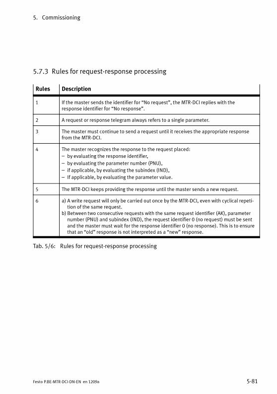
5. Commissioning
5-81Festo P.BE-MTR-DCI-DN-EN en 1209a
5.7.3 Rules for request-response processing
Rules Description
1 If the master sends the identifier for “No request”, the MTR-DCI replies with theresponse identifier for “No response”.
2 A request or response telegram always refers to a single parameter.
3 The master must continue to send a request until it receives the appropriate responsefrom the MTR-DCI.
4 The master recognizes the response to the request placed:
– by evaluating the response identifier,
– by evaluating the parameter number (PNU),
– if applicable, by evaluating the subindex (IND),
– If applicable, by evaluating the parameter value.
5 The MTR-DCI keeps providing the response until the master sends a new request.
6 a) A write request will only be carried out once by the MTR-DCI, even with cyclical repeti-tion of the same request.
b) Between two consecutive requests with the same request identifier (AK), parameternumber (PNU) and subindex (IND), the request identifier 0 (no request) must be sentand the master must wait for the response identifier 0 (no response). This is to ensurethat an “old” response is not interpreted as a “new” response.
Tab. 5/6: Rules for request-response processing

5. Commissioning
5-82 Festo P.BE-MTR-DCI-DN-EN en 1209a
Sequence of parameter processing
CautionObserve the following when modifying parameters:An FHPP control signal, which is to refer to a modifiedparameter, may only follow when the response identifier“Parameter value transferred” is received for the relevantparameter and if applicable for the index.
If, e.g. a position value in a position register is to be modifiedand if movement is then to be made to this position, the posi-tioning command must not be given until the MTR-DCI hascompleted and confirmed the modification of the positionregister.
CautionIn order to be sure that an “old” response cannot be inter-preted as a “new” response, the request identifier 0 (norequest) must be sent and the response identifier 0 (noresponse) must then be received between two consecutiverequests with the same request identifier (AK), parameternumber (PNU) and subindex (IND).
Fault evaluation
In the case of requests which cannot be carried out, the slaveresponds as follows:
– Output of response identifier = 7
– Output of a fault number in bytes 7 and 8 of the para-meter channel (FPC).

5. Commissioning
5-83Festo P.BE-MTR-DCI-DN-EN en 1209a
5.7.4 Parameterisation example
The following tables show an example of parameterising apositioning task in the position set table via FPC (Festo Para-meter Channel).
Step 1 Output status of the 8 bytes of FPC data:
Byte 1 Byte 2 Byte 3 Byte 4 Byte 5 Byte 6 Byte 7 Byte 8
Reserved Subindex ReqID/ResID + PNU Parameter value
O data 0x00 0x00 0x00 0x00 0x00 0x00 0x00 0x00
I data 0x00 0x00 0x00 0x00 0x00 0x00 0x00 0x00
Step 2 Write record number 1 with absolute positioning:PNU 401, subindex 2 – modify parameter value, array, byte:ReqID 12 (0xC) with value 0x00.
Byte 1 Byte 2 Byte 3 Byte 4 Byte 5 Byte 6 Byte 7 Byte 8
Reserved Subindex ReqID/ResID + PNU Parameter value
O data 0x00 0x02 0xC1 0x91 Unused Unused Unused 0x00
I data 0x00 0x02 0xC1 0x91 0x00 0x00 0x00 0x00
Step 3 After receiving the I-data with ResID 0xC send O-data withReqID = 0x0 and wait for I-data with ResID = 0x0:
Byte 1 Byte 2 Byte 3 Byte 4 Byte 5 Byte 6 Byte 7 Byte 8
Reserved Subindex ReqID/ResID + PNU Parameter value
O data 0x00 0x02 0x01 0x91 Unused Unused Unused 0x00
I data 0x00 0x02 0x01 0x91 0x00 0x00 0x00 0x00

5. Commissioning
5-84 Festo P.BE-MTR-DCI-DN-EN en 1209a
Step 4 Write record number 1 with target position 0x1234 (decimal4660 increments):PNU 404, subindex 2 – modify parameter value, array, doubleword: ReqID 8 (0x8) with value 0x00001234.
Byte 1 Byte 2 Byte 3 Byte 4 Byte 5 Byte 6 Byte 7 Byte 8
Reserved Subindex ReqID/ResID + PNU Parameter value
O data 0x00 0x02 0x81 0x94 0x00 0x00 0x12 0x34
I data 0x00 0x02 0x81 0x94 0x00 0x00 0x12 0x34
Step 5 After receiving the I-data with ResID 0x8 send O-data withReqID = 0x0 and wait for I-data with ResID = 0x0:
Byte 1 Byte 2 Byte 3 Byte 4 Byte 5 Byte 6 Byte 7 Byte 8
Reserved Subindex ReqID/ResID + PNU Parameter value
O data 0x00 0x02 0x01 0x94 0x00 0x00 0x12 0x34
I data 0x00 0x02 0x01 0x94 0x00 0x00 0x12 0x34
Step 6 Write record number 1 with speed 0x7743(decimal 30531 increments/s):PNU 406, subindex 2 – modify parameter value, array, doubleword: ReqID 8 (0x8) with value 0x00007743.
Byte 1 Byte 2 Byte 3 Byte 4 Byte 5 Byte 6 Byte 7 Byte 8
Reserved Subindex ReqID/ResID + PNU Parameter value
O data 0x00 0x02 0x81 0x96 0x00 0x00 0x77 0x43
I data 0x00 0x02 0x81 0x96 0x00 0x00 0x77 0x43
Step 7 After receiving the I-data with ResID 0x8 send O-data withReqID = 0x0 and wait for I-data with ResID = 0x0:
Byte 1 Byte 2 Byte 3 Byte 4 Byte 5 Byte 6 Byte 7 Byte 8
Reserved Subindex ReqID/ResID + PNU Parameter value
O data 0x00 0x02 0x01 0x94 0x00 0x00 0x77 0x43
I data 0x00 0x02 0x01 0x94 0x00 0x00 0x77 0x43
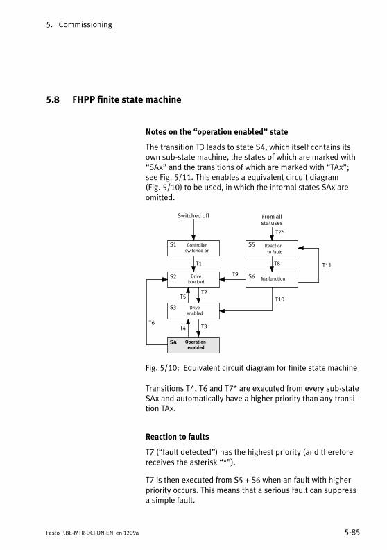
5. Commissioning
5-85Festo P.BE-MTR-DCI-DN-EN en 1209a
5.8 FHPP finite state machine
Notes on the “operation enabled” state
The transition T3 leads to state S4, which itself contains itsown sub-state machine, the states of which are marked with“SAx” and the transitions of which are marked with “TAx”;see Fig. 5/11. This enables a equivalent circuit diagram(Fig. 5/10) to be used, in which the internal states SAx areomitted.
Switched off
S1 Controllerswitched on
S3 Driveenabled
S2 Driveblocked
S5 Reaction
to fault
S6 Malfunction
From allstatuses
Operationenabled
T6
T2T5
T3T4
T1
T7*
T8
T10
T9
S5
T11
S4
Fig. 5/10: Equivalent circuit diagram for finite state machine
Transitions T4, T6 and T7* are executed from every sub-stateSAx and automatically have a higher priority than any transi-tion TAx.
Reaction to faults
T7 (“fault detected”) has the highest priority (and thereforereceives the asterisk “*”).
T7 is then executed from S5 + S6 when an fault with higherpriority occurs. This means that a serious fault can suppressa simple fault.

5. Commissioning
5-86 Festo P.BE-MTR-DCI-DN-EN en 1209a
T7* always has thehighest priority.
Switched off
S1
Controllerswitched on
S4
Driveenabled
S2
DriveBlocked
SA1
Ready
SA5
Jogpositive
SA6
Jognegative
SA4
Homingis running
SA2
Positioning taskactive
SA3
Intermediate stop
S5
Reactionto faults
S6
Fault
From allstates
S4
Operation enabled
T6
TA11
TA12
TA9
TA10
TA3
TA6
TA4
TA5
TA7
TA8
TA1TA2
T2T5
T3T4
T1
T7*
T8
T10
T9
S5
T11
Fig. 5/11: Finite state machine

5. Commissioning
5-87Festo P.BE-MTR-DCI-DN-EN en 1209a
5.8.1 Establish “ready to operate” status
T Internal conditions Actions of the user
T1 Drive has been switched on.No faults are ascertained.
T2 Load voltage applied.Fieldbus master is accepted as the higher-ordercontroller.
“Enable drive” = 1CCON = xxx0.xxx1
T3 “Stop” = 1CCON = xxx0.xx11
T4 “Stop” = 0CCON = xxx0.xx01
T5 “Enable drive” = 0CCON = xxx0.xxx0
T6 “Enable drive” = 0CCON = xxx0.xxx0
T7* Fault detected.
T8 Reaction to fault is complete, drive is stationary.
T9 There is no longer a fault.It was a serious fault.
“Acknowledge fault” = 0→ 1CCON = xxx0.Pxxx
T10 There is no longer a fault.It was a minor fault.
“Acknowledge fault” = 0→ 1CCON = xxx0.Pxx1
T11 Fault still exists. “Acknowledge fault” = 0→ 1CCON = xxx0.Pxx1
Key: P = positive edge, N = negative edge, x = any

5. Commissioning
5-88 Festo P.BE-MTR-DCI-DN-EN en 1209a
5.8.2 Positioning
The following always applies:Transitions T4, T6 and T7* always have priority.
TA Internal conditions Actions of the user
TA1 Homing has been carried out. Start positioning task = 0→ 1Halt = 1CCON = xxx0.xx11CPOS = 0xx0.00P1
TA2 Motion Complete = 1The current record has been completed. Thenext record is not to be executed automatically
“Halt” state is anyCCON = xxx0.xx11CPOS = 0xxx.xxx0
TA3 Motion Complete = 0 Halt = 1→ 0CCON = xxx0.xx11CPOS = 0xxx.xxx0
TA4 Halt = 1Start positioning task = 0→ 1Clear remaining positioning = 0CCON = xxx0.xx11CPOS = 00xx.xxP1
TA5 Record selection:
– An individual record has been completed.
– The next record is to be executed automati-cally.
CCON = xxx0.xx11CPOS = 0xxx.xxx1
Direct task:
– A new positioning task has arrived.
CCON = xxx0.xx11CPOS = 0xxx.xx11
TA6 Clear remaining positioning = 0→ 1CCON = xxx0.xx11CPOS = 01xx.xxxx
TA7 Start homing = 0→ 1Halt = 1CCON = xxx0.xx11CPOS = 0xx0.0Px1
Key: P = positive edge, N = negative edge, x = any
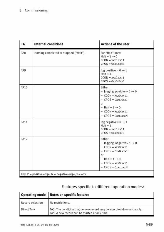
5. Commissioning
5-89Festo P.BE-MTR-DCI-DN-EN en 1209a
TA Actions of the userInternal conditions
TA8 Homing completed or stopped (“Halt”). For “Halt” only:Halt = 1→ 0CCON = xxx0.xx11CPOS = 0xxx.xxxN
TA9 Jog positive = 0→ 1Halt = 1CCON = xxx0.xx11CPOS = 0xx0.Pxx1
TA10 Either
– Jogging, positive = 1→ 0
– CCON = xxx0.xx11
– CPOS = 0xxx.0xx1or
– Halt = 1→ 0
– CCON = xxx0.xx11
– CPOS = 0xxx.xxxN
TA11 Jog negative= 0→ 1Halt = 1CCON = xxx0.xx11CPOS = 0xxP.xxx1
TA12 Either
– Jogging, negative= 1→ 0
– CCON = xxx0.xx11
– CPOS = 0xxN.xxx1
or
– Halt = 1→ 0
– CCON = xxx0.xx11
– CPOS = 0xxx.xxxN
Key: P = positive edge, N = negative edge, x = any
Features specific to different operation modes:
Operating mode Notes on specific features
Record selection No restrictions.
Direct Task TA2: The condition that no new record may be executed does not apply.TA5: A new record can be started at any time.
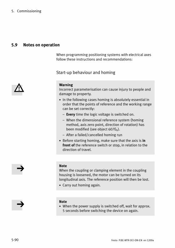
5. Commissioning
5-90 Festo P.BE-MTR-DCI-DN-EN en 1209a
5.9 Notes on operation
When programming positioning systems with electrical axesfollow these instructions and recommendations:
Start-up behaviour and homing
WarningIncorrect parameterisation can cause injury to people anddamage to property.
• In the following cases homing is absolutely essential inorder that the points of reference and the working rangecan be set correctly:
– Every time the logic voltage is switched on.
– When the dimensional reference system (homingmethod, axis zero point, direction of rotation) hasbeen modified (see object 607Eh).
– After a failed/cancelled homing run
• Before starting homing, make sure that the axis is infront of the reference switch or stop, in relation to thedirection of travel.
NoteWhen the coupling or clamping element in the couplinghousing is loosened, the motor can be turned on itslongitudinal axis. The reference position will then be lost.
• Carry out homing again.
Note• When the power supply is switched off, wait for approx.5 seconds before switching the device on again.

5. Commissioning
5-91Festo P.BE-MTR-DCI-DN-EN en 1209a
Device connection
CautionThe RS232 interface is not electrically isolated. It is notintended for permanent connection to PC systems or as acontroller interface.
• Use the connection only for parameterising and diag-nosis.
Controlling during operation
WarningDanger of injury.
Faults in parameter assignment can cause injury to peopleand damage to property when the controller is enabled.
• Only enable the controller once the axis system has beeninstalled and parameterised by technically qualifiedstaff.
CautionNote the manufacturer's specifications for the permittedoperating conditions of the motors and drives used, suchas the permitted positioning speeds, for example.
CautionDamage to components with DMES-...
Movement onto the mechanical end positions is not per-mitted during operation. When movement is made to theend positions with a heavy load, blockage may occur in theend positions.
NoteAny functions implemented for the purposes ofEMERGENCY-STOP procedures must also be taken intoaccount in the control programs.

5. Commissioning
5-92 Festo P.BE-MTR-DCI-DN-EN en 1209a
Password protection
In the factory settings, password protection is not active. Inorder to prevent unauthorised or unintentional overwriting ormodification of parameters in the device, all download andcontrol functions can be blocked.
• Recommendation:Protect the settings of your axis against undesired modifi-cations with a password:
– FCT password protection (8 characters, see MTR-DCIplug-in help).
– HMI password protection for MTR-DCI-...-H2-...(3 characters; see chapter 4.5).
Care and maintenance
The motor units do not require maintenance during theirspecified service life. Follow the maintenance instructions forthe accessory components.

Diagnosis and error display
6-1Festo P.BE-MTR-DCI-DN-EN en 1209a
Chapter 6
Diagnosis and error display
6. Diagnosis and error display
6-2 Festo P.BE-MTR-DCI-DN-EN en 1209a
Contents
6. Diagnosis and error display 6-1. . . . . . . . . . . . . . . . . . . . . . . . . . . . . . . . . . . . . .
6.1 Overview of diagnostic options 6-3. . . . . . . . . . . . . . . . . . . . . . . . . . . . . . . . . . . .
6.2 LED status displays 6-5. . . . . . . . . . . . . . . . . . . . . . . . . . . . . . . . . . . . . . . . . . . . .
6.3 Fault messages 6-7. . . . . . . . . . . . . . . . . . . . . . . . . . . . . . . . . . . . . . . . . . . . . . . . .
6.3.1 Overview 6-7. . . . . . . . . . . . . . . . . . . . . . . . . . . . . . . . . . . . . . . . . . . . . .
6.3.2 Description of the messages, warnings, and faults 6-8. . . . . . . . . . . . .
6.4 Diagnosis using Fieldbus 6-12. . . . . . . . . . . . . . . . . . . . . . . . . . . . . . . . . . . . . . . . .
6.4.1 Overview 6-12. . . . . . . . . . . . . . . . . . . . . . . . . . . . . . . . . . . . . . . . . . . . . .
6.4.2 Diagnostic memory 6-13. . . . . . . . . . . . . . . . . . . . . . . . . . . . . . . . . . . . . .
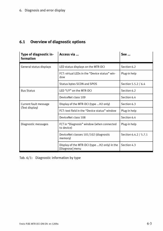
6. Diagnosis and error display
6-3Festo P.BE-MTR-DCI-DN-EN en 1209a
6.1 Overview of diagnostic options
Type of diagnostic in-formation
Access via ... See ...
General status displays LED status displays on the MTR-DCI Section 6.2
FCT: virtual LEDs in the “Device status” win-dow
Plug-in help
Status bytes SCON and SPOS Section 5.5.2 / 6.4
Bus Status LED “I/F” on the MTR-DCI Section 6.2
DeviceNet class 109 Section 6.4
Current fault message(Text display)
Display of the MTR-DCI (type ...H2 only) Section 6.3
FCT: text field in the “Device status” window Plug-in help
DeviceNet class 108 Section 6.4
Diagnostic messages FCT in “Diagnosis” window (when connectedto device)
Plug-in help
DeviceNet classes 101/102 (diagnosticmemory)
Section 6.4.2 / 5.7.1
Display of the MTR-DCI (type ...H2 only) in the[Diagnose] menu
Section 4.3
Tab. 6/1: Diagnostic information by type

6. Diagnosis and error display
6-4 Festo P.BE-MTR-DCI-DN-EN en 1209a
Access Brief description Advantages /properties
See...
LEDs The LEDs indicate “ready to operate”status, positioning status, faults andbus status.
Fast“on-the-spot”recognition offaults
Section 6.2
Control panel onthe MTR-DCI-...-H2
On the LCD display:messages, warnings and faults
Fast“on-the-spot”diagnosis
Section 6.3
In the [Diagnostic] menu:Diagnostic data, operation mode, cur-rent positioning set, target and actualpositions, speed, and information oncommunication via Fieldbus
Detailed“on-the-spot” di-agnosis
Section 4.3
Festo Configur-ation Tool
With active device connection:
– Display of the current position set,
target and actual positions, andspeed.
– Display of the operation mode,
special outputs and operatingstates, and fault messages from theconnected MTR-DCI.
– Virtual LEDs in the “Device status”
window
– Display of the bus status
– Display of the diagnostic memory
Detailed diag-nosis during com-missioning
MTR-DCI plug-inhelp
FHPP/DeviceNet Diagnosis via FHPP status bytes SCONand SPOS
Simple diagnosisvia Fieldbus
Section 6.4
Expanded access to diagnostic data,e.g. diagnostic memory
Detailed diag-nosis via Fieldbus
Section 6.4.2
Tab. 6/2: Diagnostic information by access

6. Diagnosis and error display
6-5Festo P.BE-MTR-DCI-DN-EN en 1209a
6.2 LED status displays
1 Power LED
2 I/F LED
3 Error LED
1 2 3
Fig. 6/1: LEDs on the control panel of the MTR-DCI-...
POWER GREEN Power supply
ON Load and logic voltages applied.
FLASH-ING
Logic voltage is applied.Load voltage is not applied.
OUT No voltage is applied.
Tab. 6/3: “Power” LED
ERROR RED Fault display
ON Fault. Device not ready for operation. Checkcause and rectify if necessary; see sec-tion 6.3.
FLASH-ING
Warning. Check cause and rectify ifnecessary; see section 6.3.
OUT No internal fault reported.
Tab. 6/4: “Error” LED

6. Diagnosis and error display
6-6 Festo P.BE-MTR-DCI-DN-EN en 1209a
I/F Bus Status 1)
GREEN “Network”
ON
OFF
ON “Operational”
– System in “operational” state.
ON
OFF
FLASH-ING
“Device in Standby”
– MTR-DCI not yet place in the “Operational” state by the
master.
RED “Modules”
ON
OFF
OUT “No Power / BUS-Off”
– No bus connection or bus voltage not present.
ON
OFF
FLASH-ING
Warning “Minor fault”
– A recoverable fault has occurred, e.g. timeout when
establishing a connection.
ON
OFF
ON Fault “Unrecoverable fault”
– A irrecoverable fault has occurred, e.g. a duplicate MAC ID
was recognised.
1) Combined network and module status display as per the DeviceNet specification
Tab. 6/5: “I/F” LED

6. Diagnosis and error display
6-7Festo P.BE-MTR-DCI-DN-EN en 1209a
6.3 Fault messages
6.3.1 Overview
Cate-gory
Name, display Description DeviceError 1)
Faultnumber
FaultLED
Statusbytes 2)
Fault POSITION ERROR Following error 0x0001 31 ON FAULT, DEV
Fault MOTOR STOP Motor stop 0x0002 106 ON FAULT
Fault HOMING-ERROR Reference runfault
0x0004 32 ON FAULT
Fault OVERHEATING Overtemperature(ActTemp > 80°C)
0x0008 101 ON FAULT
Fault LOAD-POWER-DOWN
Load voltagemonitoring
0x0010 70 ON FAULT
Fault I2t-ERROR Current moni-toring (i2t)
0x0020 100 ON FAULT
Fault HARDWARE-ERROR Device fault 0x0040 52 ON FAULT
Fault TARGET POSITIONOUT OF LIMIT!
Nominal positionnot reachable
0x0080 2 ON FAULT
Warning ILLEGAL RECORD Invalid recordnumber
0x0100 3 FLASH-ING
WARN
Fault PLEASE ENFORCEHOMING RUN!
Homing required 0x0200 1 ON FAULT
Warning STANDSTILL-WARNING
Standstill moni-toring
0x4000 36 FLASH-ING
WARN,STILL
Fault INIT NO PARA-METER ERROR
Fault:Bus parametersnot set.
0x8000 51 ON FAULT
1) See PNU 205 / CI 2FF1/002) For FHPP status bytes, see section 5.5.2

6. Diagnosis and error display
6-8 Festo P.BE-MTR-DCI-DN-EN en 1209a
Cate-gory
Statusbytes 2)
FaultLED
Faultnumber
DeviceError 1)
DescriptionName, display
Warning HOT TEMPERATURE Temperature toohigh
– – FLASHING WARN
Warning COLD TEMPERA-TURE
Temperature toolow
– – FLASHING WARN
1) See PNU 205 / CI 2FF1/002) For FHPP status bytes, see section 5.5.2
Tab. 6/6: Faults and warnings with fault numbers and fault bits
6.3.2 Description of the messages, warnings, and faults
Messages Messages give information regarding operating states
Notification Cause
Attention!Motor moves...
Message before the start of a positioning move-ment. After confirmation with the <ENTER> button,the drive starts moving.
Profile velocity= 0. Please setv.
The menu command [Move position set] is notbeing executed because the positioning speed ofthe position set record is v = 0. Modify theparameter assignment or select a differentposition set record.
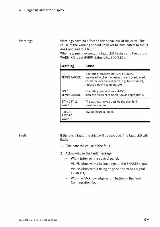
6. Diagnosis and error display
6-9Festo P.BE-MTR-DCI-DN-EN en 1209a
Warnings Warnings have no effect on the behaviour of the drive. Thecause of the warning should however be eliminated so that itdoes not lead to a fault.When a warning occurs, the fault LED flashes and the outputWARNING is set (FHPP status bits, SCON.B2).
Warning Cause
HOTTEMPERATURE
Operating temperature 70°C < T < 80°C,may need to check whether drive is overloaded,check the mechanical parts (e.g. for stiffness),reduce ambient temperature.
COLDTEMPERATURE
Operating temperature < -10°C,increase ambient temperature as appropriate.
STANDSTILL-WARNING
The axis has moved outside the standstillposition window.
ILLEGALRECORDWARNING
Invalid record number.
Fault If there is a fault, the drive will be stopped. The fault LED willflash.
1. Eliminate the cause of the fault.
2. Acknowledge the fault message:
– With <Enter> on the control panel,
– Via Fieldbus with a falling edge on the ENABLE signal,
– Via Fieldbus with a rising edge on the RESET signalCCON.B3,
– With the “Acknowledge error” button in the FestoConfiguration Tool.

6. Diagnosis and error display
6-10 Festo P.BE-MTR-DCI-DN-EN en 1209a
Fault Possible cause Remedy
DEVICENET INIT NOPARAMETER ERROR
Essential bus parameters not set.– MTR-DCI not on the bus.
• Set bus parameters (see sec-tion 5.2.7):– MAC-ID– Bit rate– I/O Data length
HARDWARE ERROR Device fault (EEPROM defective, oruser data damaged)
• Contact Festo Service.
I2t-ERROR Current monitoring i2t.– The drive is blocked
• Check the drive mechanism.
HOMING ERROR Error during homing– Homing run interrupted– Homing switch defective
• If necessary, check the function ofthe homing switch.
• It is essential that you repeathoming.
LOAD-POWER-DOWN Voltage monitoring– Load voltage too low
MTR-DCI 32/42/52: U < 18 VMTR-DCI 62: U < 34 V
– Voltage drops under load
• Check the power supply:– Power supply unit too weak?– Supply line too long?
MOTOR STOP Error during the positioning proced-ure– A positioning procedure has been
aborted on the control panel withEMERG.STOP (button “Menu”).
• Acknowledge the error on thecontrol panel with “Enter”
OVERHEATING Overheating(Operating temperature > 80 °C).– Temperature of power stage too
high.– Ambient temperature too high
• Check:– That the limits are complied
with (motor characteristiccurves),
– the mechanical parts e.g. forstiffness.
• If necessary, reduce the ambienttemperature.
PLEASE ENFORCEHOMING RUN
When starting a position set:– A valid homing process has not
yet been conducted.– Due to a logic voltage failure the
reference position has been lost.
• Carry out homing.
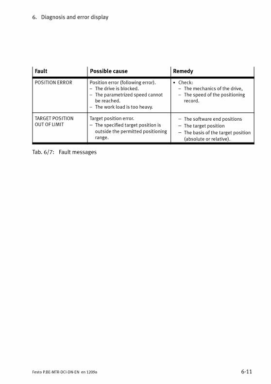
6. Diagnosis and error display
6-11Festo P.BE-MTR-DCI-DN-EN en 1209a
Fault RemedyPossible cause
POSITION ERROR Position error (following error).– The drive is blocked.– The parametrized speed cannot
be reached.– The work load is too heavy.
• Check:– The mechanics of the drive,– The speed of the positioning
record.
TARGET POSITIONOUT OF LIMIT
Target position error.
– The specified target position is
outside the permitted positioningrange.
– The software end positions
– The target position
– The basis of the target position
(absolute or relative).
Tab. 6/7: Fault messages

6. Diagnosis and error display
6-12 Festo P.BE-MTR-DCI-DN-EN en 1209a
6.4 Diagnosis using Fieldbus
6.4.1 Overview
The MTR-DCI supports the following diagnostic options overDeviceNet:
– Status bytes (access via FHPP, see section 5.5.2)– SCON.B2: WARN – Warning– SCON.B3: FAULT – Fault– SPOS.B5: DEV – Following error– SPOS.B6: STILL – Standstill monitoring.
– DeviceNet classes 101, 102, 108, 109.
DeviceNet class INST 1) ATTR PNU 2) See...
101(65h)
Diagnostic mem-ory
Diagnosis event 01h...10h 01h 200 Section6.4.2B.2.6Malfunction number 01h...10h 02h 201
Timestamp 01h...10h 03h 202
102(66h)
Diagnostic mem-ory administration
– Record fault
– Resolution
– Delete buffer
– Number of entries
01h01h01h01h
01h02h03h04h
204 SectionB.2.6
108(6Ch)
Current fault, warnings 01h 01h 205 Section6.3 /B.2.6
109(6Dh)
Fieldbus dia-gnostics
– Bus status– Current bit rate– Current MAC ID– Current I/O data
length
01h01h01h01h
01h02h04h05h
206 SectionB.2.6
1) Access via Explicit Messaging2) Access via I/O Messaging (FHPP-FPC)
Tab. 6/8: Diagnosis via Fieldbus: DeviceNet classes

6. Diagnosis and error display
6-13Festo P.BE-MTR-DCI-DN-EN en 1209a
6.4.2 Diagnostic memory
The diagnostic memory contains the last 16 diagnostic mess-ages. It is secured if possible in the event of power failure.If it is full, the oldest element will be overwritten (circularbuffer).
Structure of the diagnostic memory
Parameter 1) PNU 200 PNU 201 PNU 202
Format uint8 uint16 uint32
Meaning Diagnosis event Fault number Time
Subindex 1 Current diagnostic message
Subindex 2 Previous diagnostic message
... ...
Subindex 16 Oldest diagnostic message
1) Access via Explicit Messaging see Tab. 6/8
Tab. 6/9: Diagnostic memory: Structure
Configuration of the diagnostic memory (PNU 204)
SI Description Specifi-cation
Min. Max.
1 = 1: Record incoming and outgoing 2) faults= 2: Record only incoming faults
1 1 2
2 = 1: Time stamp resolution 10 ms= 2: Time stamp resolution 1 ms
1 1 2
3 Deleting the diagnostic memory.
– Writing with value = 1 deletes the diagnostic memory
– Read will always be answered with value = 0.
0 0 1
4 Number of valid entries in the diagnostic memory. 0 0 16
1) Access via Explicit Messaging see Tab. 6/82) Outgoing fault = time when the fault was acknowledged.
Tab. 6/10: Diagnostic memory: configuration

6. Diagnosis and error display
6-14 Festo P.BE-MTR-DCI-DN-EN en 1209a
The faults are divided into logical groups according to thefault numbers.
Group Name Comment
0 – No fault active
1 ... 19 Execution fault Examples: no homing, nominal position outside software endpositions, nominal value calculation not possible.Although the system is OK, a user command cannot be ex-ecuted. In most cases there is a fault in operation.Source: sequence control, controller.
20..29 Parameter fault Example: software end positions outside the effective stroke.A parameter lies within the limit values, allowing it to bewritten by the user. During the recalculation by the controller,it was found to be invalid in the context of the other para-meters.Note: invalid parameters are rejected by the parameter proto-col and do not generate a fault in the controller.
30..49 Closed-loop con-trollers
Examples: Positioning timeout, homing not successful, fol-lowing error too large, ...The task could not be executed correctly. No hardware faultcould be detected. Source: closed-loop controllers.
50..69 Initialisation Fault when initialising the controller.
70..79 Controller runtime Controller runtime fault: Undervoltage, checksum.
80 ... 89 – Reserved
90 ... 99 – Reserved
100 ... 109 Motor runtime Motor runtime: undervoltage, overtemperature, ...
110 ... 119 – Reserved
Tab. 6/11: Overview of fault numbers
A detailed description of the warnings and faults can befound in section 6.3.2.

Technical appendix
A-1Festo P.BE-MTR-DCI-DN-EN en 1209a
Appendix A
Technical appendix
A. Technical appendix
A-2 Festo P.BE-MTR-DCI-DN-EN en 1209a
Contents
A. Technical appendix A-1. . . . . . . . . . . . . . . . . . . . . . . . . . . . . . . . . . . . . . . . . . . . .
A.1 Technical data A-3. . . . . . . . . . . . . . . . . . . . . . . . . . . . . . . . . . . . . . . . . . . . . . . . . .
A.2 Accessories A-6. . . . . . . . . . . . . . . . . . . . . . . . . . . . . . . . . . . . . . . . . . . . . . . . . . . .
A.3 Motor characteristic curves A-8. . . . . . . . . . . . . . . . . . . . . . . . . . . . . . . . . . . . . . .
A.4 Conversion of units of measurement A-14. . . . . . . . . . . . . . . . . . . . . . . . . . . . . . .
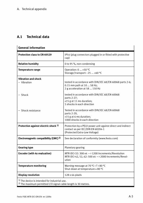
A. Technical appendix
A-3Festo P.BE-MTR-DCI-DN-EN en 1209a
A.1 Technical data
General information
Protection class to EN 60529 IP54 (plug connectors plugged in or fitted with protectivecap)
Relative humidity 0 to 95 %, non-condensing
Temperature range Operation: 0 ... +50 °CStorage/transport: -25 ... +60 °C
Vibration and shock
– Vibration tested in accordance with DIN/IEC 68/EN 60068 parts 2-6;0.15 mm path at 10 ... 58 Hz;2 g acceleration at 58 ... 150 Hz
– Shock tested in accordance with DIN/IEC 68/EN 60068parts 2-27;±15 g at 11 ms duration;5 shocks in each direction
– Shock resistance Tested in accordance with DIN/IEC 68/EN 60068parts 2-29,±15 g at 6 ms duration;1000 shocks in each direction
Protection against electric shock 1) Protection by a PELV power unit against direct and indirectcontact as per IEC/DIN EN 60204-1(Protected Extra-Low Voltage)
Electromagnetic compatibility (EMC) 2) See declaration of conformity (www.festo.com)
Gearing type Planetary gearing
Encoder (with 4x evaluation) MTR-DCI-32: 300 x4—> 1200 Increments/RevolutionMTR-DCI-42, 52, 62: 500 x4—> 2000 Increments/Revol-ution
Temperature monitoring Warning message at 70 °C < T < 80 °CShut-down at temperature ≥ 80 °C
Display resolution 128 x 64 pixels
1) The device is intended for industrial use.2) The maximum permitted I/O signal cable length is 30 metres.

A. Technical appendix
A-4 Festo P.BE-MTR-DCI-DN-EN en 1209a
Motor data 32 42 52 62
Rated torque(Motor without gearbox)
[mNm] 32 110 300 800
MTR-DCI-...-G7: Gear reduction 6.75:1; 1-stage
Gear units 1)
– Drive output speed– Torsional backlash– Drive output torque– Efficiency
[rpm][°][Nm]–
481≤ 1.90.150.75
444≤ 1.30.590.8
444≤ 1.11.620.8
504≤ 1.03.780.8
Mass moment of inertia
– Rotor
– Gearing
[kg cm2][kg cm2]
0.0240.00089
0.03230.00235
1.2090.01132
3.30.017
MTR-DCI-...-G14: Gear reduction 13.73:1; 2-stage
Gear units 1)
– Drive output speed– Torsional backlash– Drive output torque– Efficiency
[rpm][°][Nm]–
237≤ 1.550.290.7
218≤ 0.951.130.75
218≤ 0.753.080.75
248≤ 1.57.200.75
Mass moment of inertia
– Rotor
– Gearing
[kg cm2] 0.0240.00149
0.3230.00441
1.2090.01711
3.30.035
MTR-DCI-...-G22: Gear reduction ratio 22.21:1
Gear units 1)
– Drive output speed– Torsional backlash– Drive output torque– Efficiency
[rpm][°][Nm]–
– – – 153≤ 1.511.660.75
Mass moment of inertia
– Rotor
– Gearing
[kg cm2][kg cm2]
– – – 3.30.022
1) For permitted loading of gear shaft, see chapter 2, Tab. 2/2
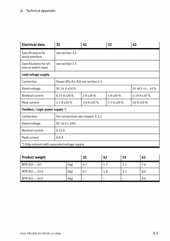
A. Technical appendix
A-5Festo P.BE-MTR-DCI-DN-EN en 1209a
Electrical data 32 42 52 62
Specifications forserial interface
see section 3.4
Specifications for ref-erence switch input
see section 3.5
Load voltage supply
Connection Power (Pin A1, A2) see section 3.3
Rated voltage DC 24 V ±10 % DC 48 V +5...-10 %
Nominal current 0.73 A ±20 % 2 A ±20 % 5 A ±20 % 6.19 A ±20 %
Peak current 2.1 A ±20 % 3.8 A ±20 % 7.7 A ±20 % 20 A ±20 %
Fieldbus / Logic power supply *)
Connection For connections see chapter 3.3.2
Rated voltage DC 24 V ± 10%
Nominal current 0.15 A
Peak current 0.8 A
*) Only relevant with separated voltage supply.
Product weight 32 42 52 62
MTR-DCI-...-G7 [kg] 0.7 1.7 3.1 7.6
MTR-DCI-...-G14 [kg] 0.7 1.8 3.3 8.0
MTR-DCI-...-G22 [kg] – – – 8.0
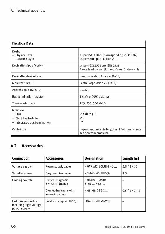
A. Technical appendix
A-6 Festo P.BE-MTR-DCI-DN-EN en 1209a
Fieldbus Data
Design– Physical layer– Data link layer
as per ISO 11898 (corresponding to DS 102)as per CAN specification 2.0
DeviceNet Specification as per IEC62026 and EN50325Predefined connection set: Group 2 slave only
DeviceNet device type Communication Adapter (0x12)
Manufacturer ID Festo Corporation 26 (0x1A)
Address area (MAC ID) 0 ... 63
Bus termination resistor 121 Ω, 0.25W, external
Transmission rate 125, 250, 500 kbit/s
Interface
– Plug
– Electrical isolation
– Integrated bus termination
D-Sub, 9-pinyesno
Cable type dependent on cable length and fieldbus bit rate,see controller manual
A.2 Accessories
Connection Accessories Designation Length [m]
Voltage supply Power supply cable KPWR-MC-1-SUB-9HC-... 2.5 / 5 / 10
Serial interface Programming cable KDI-MC-M8-SUB-9-... 2.5
Homing Switch Switch, magneticSwitch, inductive
SMT-8M-...-M8DSIEN-...-M8B-...
–
Connecting cable withscrew-type lock
KM8-M8-GSGD.... 0.5 / 1 / 2 / 5
Fieldbus connectionincluding logic voltagepower supply
Fieldbus adapter (IP54) FBA-CO-SUB-9-M12 –
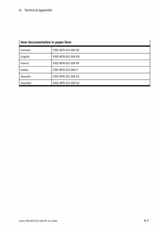
A. Technical appendix
A-7Festo P.BE-MTR-DCI-DN-EN en 1209a
User documentation in paper form
German P.BE-MTR-DCI-DN-DE
English P.BE-MTR-DCI-DN-EN
French P.BE-MTR-DCI-DN-FR
Italian P.BE-MTR-DCI-DN-IT
Spanish P.BE-MTR-DCI-DN-ES
Swedish P.BE-MTR-DCI-DN-SV

A. Technical appendix
A-8 Festo P.BE-MTR-DCI-DN-EN en 1209a
A.3 Motor characteristic curves
1 Gear shaft driving torque M [Nm]
2 Current I [A]
3 Recommended operation
4 Impermissible range
5 Overload range
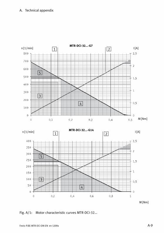
A. Technical appendix
A-9Festo P.BE-MTR-DCI-DN-EN en 1209a
MTR-DCI-32...-G14
MTR-DCI-32...-G7I [A]
M [Nm]
n [1/min] 1 2
3
4
5
I [A]
M [Nm]
n [1/min] 1 2
3
4
5
Fig. A/1: Motor characteristic curves MTR-DCI-32...
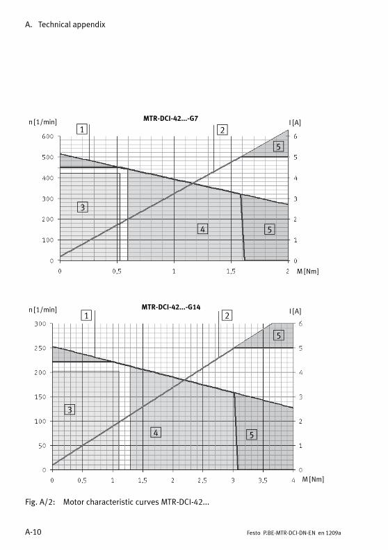
A. Technical appendix
A-10 Festo P.BE-MTR-DCI-DN-EN en 1209a
MTR-DCI-42...-G14
MTR-DCI-42...-G7
I [A]
M [Nm]
n [1/min]1 2
3
4 5
I [A]
M [Nm]
n [1/min]1 2
3
4 5
5
5
Fig. A/2: Motor characteristic curves MTR-DCI-42...

A. Technical appendix
A-11Festo P.BE-MTR-DCI-DN-EN en 1209a
I [A]
M [Nm]
n [1/min] 1 2
3 4 5
5
MTR-DCI-52...-G14
MTR-DCI-52...-G7
I [A]
M [Nm]
n [1/min]1 2
3 4 5
5
Fig. A/3: Motor characteristic curves MTR-DCI-52...
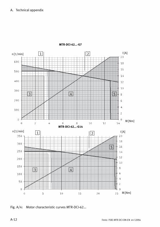
A. Technical appendix
A-12 Festo P.BE-MTR-DCI-DN-EN en 1209a
MTR-DCI-62...-G14
MTR-DCI-62...-G7
I [A]
M [Nm]
n [1/min] 1 2
3 4
5
I [A]
M [Nm]
n [1/min] 1 2
3 4 5
Fig. A/4: Motor characteristic curves MTR-DCI-62...

A. Technical appendix
A-13Festo P.BE-MTR-DCI-DN-EN en 1209a
MTR-DCI-62...-G22
I [A]
M [Nm]
n [1/min] 1 2
3 4
5
Fig. A/5: Motor characteristic curves MTR-DCI-62...

A. Technical appendix
A-14 Festo P.BE-MTR-DCI-DN-EN en 1209a
A.4 Conversion of units of measurement
A measuring system must be defined to allow the electricalaxis parameters to be defined. To allow simple parameterisa-tion for different application cases, the control panel or FCTcan be used to configure the controller so that the user candirectly enter or read all dimensions in the desired units atthe drive. For example:
– Metric measuring system for linear movements (mm,mm/s, mm/s2)
– Angular measuring system for rotational movements(degree, degree/s, degree/s2) or (rev, rev/s, rev/s2)
– Imperial measuring system for linear movements (inch,inch/s, inch/s2)
Every physical value (position, speed, and acceleration) isconverted to the respective measuring system via aconversion factor.
In the controller, all parameters are always saved inincrement specifications (inc, inc/s, inc/s2) and not converteduntil they are written or read. For the display, conversion fromthe internal basis system into the (pre)set measuring systemtakes place within the firmware; for representation on the PCmonitor within the FCT software. In this way, the user doesnot need to carry out conversion when entering values orwhen reading on the control panel or in the FCT.Direct transfer of values via the serial interface with CI com-mands always takes place in the base system and firstrequires conversion into increments.
Conversion is carried out via the parameters:
– Feed constant (depending on the axis type)
– Gear reduction ratio
– Encoder resolution = physical measuring steps per motorrevolution. With MTR-DCI: pulse quadruplication by digitalinterpolation

A. Technical appendix
A-15Festo P.BE-MTR-DCI-DN-EN en 1209a
Parameter MTR-DCI-32 MTR-DCI-42 MTR-DCI-52 MTR-DCI-62
feed 1) DMES-18-...:1500 [μm/rev]
DMES-25-...:2500 [μm/rev]
DMES-40-...:4000 [μm/rev]
DMES-63-...:6000 [μm/rev]
enc 2) 300 x 4 =1200 [incr/rev]
500 x 4 = 2000 [incr/rev]
gear 3) MTR-DCI-...-G7 (6.75:1) > 27:4MTR-DCI-...-G14 (13.73:1) > 3969:289MTR-DCI-...-G22 (22.2:1) > 1710:77
1) Feed constant: depends on axis type, here type DMES-...2) Encoder resolution for MTR-DCI: pulse quadruplication by digital interpolation3) Gear reduction: specification in 2 natural numbers for numerator and denominator of the fraction
Tab. A/12: Basis parameter for the measuring system
Drive Conversion factors CF
Increments< >millimetres
Increments = millimetres*CF
Millimetres = increments/CF
Increments< > inches
Increments = inches*CF
Inches = increments/CF
MTR-DCI-32-...(+DMES-18)
-G7-G14
540010986.851211
1371627906.602076
MTR-DCI-42-...(+DMES-25)
-G7-G14
540010986.851211
13716027906.602076
MTR-DCI-52-...(+DMES-40)
-G7-G14
33756866.782007
8572517441.626298
MTR-DCI-62-...(+DMES-63)
-G7-G14-G22
22504577.8546717402.597403
5715011627.75086518802.597403
Tab. A/13: Special conversion factors for the MTR-DCI with DMES-...

A. Technical appendix
A-16 Festo P.BE-MTR-DCI-DN-EN en 1209a
General conversion factors UF
1 [inch] = 25.4 [mm]
1 [inch] = 0.0254 [m]
1 [°] =1
360[rot]
[μm]> [inc]UFm inc
m =enc× gear
feedm
incrot ×rotrot
m
rot
[μinch]> [inc]
UFinch inc
inch = enc× gear
feedinch
incrot ×rotrot
inch
rot
=
enc× gear
feedm ×1
0,0254
incrot ×
rotrot
m
rot×
inch
m
= UFm × 0.0254 inc
m×minch
[rev]> [inc]UFrot incrot = enc× gear inc
rot×
rotrot
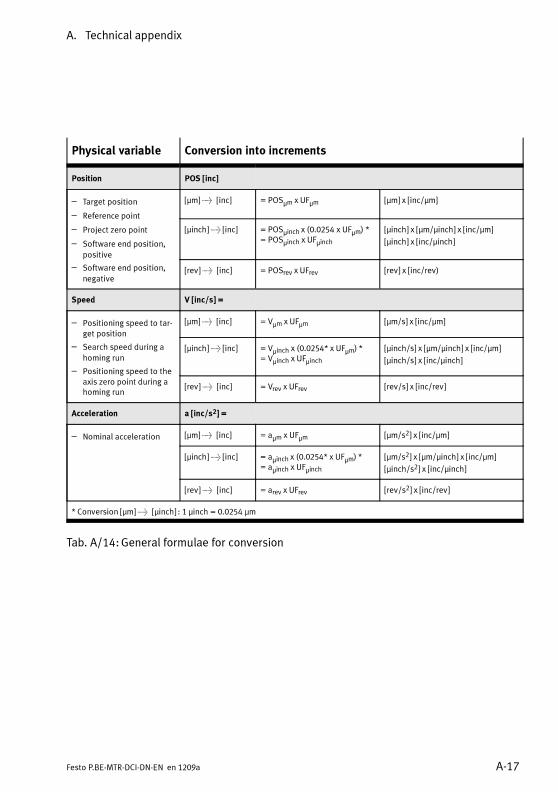
A. Technical appendix
A-17Festo P.BE-MTR-DCI-DN-EN en 1209a
Physical variable Conversion into increments
Position POS [inc]
– Target position
– Reference point
– Project zero point
– Software end position,
positive
– Software end position,
negative
[µm]> [inc] = POSìm x UF
ìm [µm] x [inc/µm]
[µinch]> [inc] = POSìinch x (0.0254 x UF
ìm) *= POS
ìinch x UFìinch
[µinch] x [µm/µinch] x [inc/µm]
[µinch] x [inc/µinch]
[rev]> [inc] = POSrev x UFrev [rev] x [inc/rev)
Speed V [inc/s] =
– Positioning speed to tar-get position
– Search speed during a
homing run
– Positioning speed to theaxis zero point during ahoming run
[µm]> [inc] = Vìm x UF
ìm [ìm/s] x [inc/ìm]
[µinch]> [inc] = Vìinch x (0.0254* x UFìm) *
= Vìinch x UFìinch
[ìinch/s] x [ìm/ìinch] x [inc/ìm]
[ìinch/s] x [inc/ìinch]
[rev]> [inc] = Vrev x UFrev [rev/s] x [inc/rev]
Acceleration a [inc/s2] =
– Nominal acceleration [µm]> [inc] = aìm x UF
ìm [ìm/s2] x [inc/ìm]
[µinch]> [inc] = aìinch x (0.0254* x UFìm) *
= aìinch x UFìinch
[ìm/s2] x [ìm/ìinch] x [inc/ìm]
[ìinch/s2] x [inc/ìinch]
[rev]> [inc] = arev x UFrev [rev/s2] x [inc/rev]
* Conversion [µm]> [µinch] : 1 ìinch = 0.0254 ìm
Tab. A/14:General formulae for conversion

A. Technical appendix
A-18 Festo P.BE-MTR-DCI-DN-EN en 1209a

Reference – Festo DeviceNet and FHPP
B-1Festo P.BE-MTR-DCI-DN-EN en 1209a
Appendix B
Reference – Festo DeviceNet and FHPP
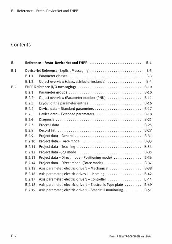
B. Reference – Festo DeviceNet and FHPP
B-2 Festo P.BE-MTR-DCI-DN-EN en 1209a
Contents
B. Reference – Festo DeviceNet and FHPP B-1. . . . . . . . . . . . . . . . . . . . . . . . . . . .
B.1 DeviceNet Reference (Explicit Messaging) B-3. . . . . . . . . . . . . . . . . . . . . . . . . . .
B.1.1 Parameter classes B-3. . . . . . . . . . . . . . . . . . . . . . . . . . . . . . . . . . . . . . .
B.1.2 Object overview (class, attribute, instance) B-4. . . . . . . . . . . . . . . . . . .
B.2 FHPP Reference (I/O messaging) B-10. . . . . . . . . . . . . . . . . . . . . . . . . . . . . . . . . .
B.2.1 Parameter groups B-10. . . . . . . . . . . . . . . . . . . . . . . . . . . . . . . . . . . . . . .
B.2.2 Object overview (Parameter number (PNU) B-11. . . . . . . . . . . . . . . . . .
B.2.3 Layout of the parameter entries B-16. . . . . . . . . . . . . . . . . . . . . . . . . . . .
B.2.4 Device data – Standard parameters B-17. . . . . . . . . . . . . . . . . . . . . . . . .
B.2.5 Device data – Extended parameters B-18. . . . . . . . . . . . . . . . . . . . . . . . .
B.2.6 Diagnosis B-21. . . . . . . . . . . . . . . . . . . . . . . . . . . . . . . . . . . . . . . . . . . . . .
B.2.7 Process data B-25. . . . . . . . . . . . . . . . . . . . . . . . . . . . . . . . . . . . . . . . . . .
B.2.8 Record list B-27. . . . . . . . . . . . . . . . . . . . . . . . . . . . . . . . . . . . . . . . . . . . .
B.2.9 Project data – General B-31. . . . . . . . . . . . . . . . . . . . . . . . . . . . . . . . . . . .
B.2.10 Project data – Force mode B-33. . . . . . . . . . . . . . . . . . . . . . . . . . . . . . . .
B.2.11 Project data – Teaching B-34. . . . . . . . . . . . . . . . . . . . . . . . . . . . . . . . . . .
B.2.12 Project data – Jog mode B-35. . . . . . . . . . . . . . . . . . . . . . . . . . . . . . . . . .
B.2.13 Project data – Direct mode: (Positioning mode) B-36. . . . . . . . . . . . . . .
B.2.14 Project data – Direct mode: (Force mode) B-37. . . . . . . . . . . . . . . . . . . .
B.2.15 Axis parameter, electric drive 1 – Mechanical B-38. . . . . . . . . . . . . . . . .
B.2.16 Axis parameter, electric drives 1 – Homing B-42. . . . . . . . . . . . . . . . . . .
B.2.17 Axis parameter, electric drive 1 – Controller B-44. . . . . . . . . . . . . . . . . .
B.2.18 Axis parameter, electric drive 1 – Electronic Type plate B-49. . . . . . . . .
B.2.19 Axis parameter, electric drive 1 – Standstill monitoring B-51. . . . . . . . .

B. Reference – Festo DeviceNet and FHPP
B-3Festo P.BE-MTR-DCI-DN-EN en 1209a
B.1 DeviceNet Reference (Explicit Messaging)
B.1.1 Parameter classes
Class CLASS 1) Description
Device data 0x64 (100) Device identification and device-specific settings, versionnumbers, passwords, control panel queries, etc.
Diagnosis Buffer 0x65 (101) Memory for diagnostic events: fault numbers, fault time,incoming/outgoing event
Diagnosis BufferAdministration(Diagnosis buffermanagement)
0x66 (102) Management of the diagnosis buffer
Process Data 0x67 (103) Current nominal and actual values, local I/Os, status data,record number, etc.
Record Sets 0x68 (104) A record contains all the nominal value parameters requiredfor a positioning procedure
Project Data 0x69 (105) Basic project settings. Maximum speed and acceleration,offset project zero point etc. --> Parameters are the basisfor the record list
Factor group 0x6A (106) Reserved
Axis Data 0x6B (107) All axis-specific parameters for electric drives. Gear ratio,feed constant, homing parameters ...
System Diagnosis 0x6C (108) Read or clear the active device fault
Fieldbus diagnosisFieldbus diagnostics
0x6D (109) Current connection status and fieldbus settings, e.g. bitrate, I/O data length
1) Class number as per DeviceNet specification
Tab. B/1: Parameter classes (DeviceNet)

B. Reference – Festo DeviceNet and FHPP
B-4 Festo P.BE-MTR-DCI-DN-EN en 1209a
B.1.2 Object overview (class, attribute, instance)
The object model is used for data access via “Explicit Mess-aging” over DeviceNet. The following tables contain alldefined parameters and specify the class (CLS), attribute(ATTR) and instance (INST). For data addressing via the FPC(within the cyclic I/O data), the FHPP parameter number/sub-addressing is used.
The descriptions of the parameters can be found under thespecified FHPP parameter number PNU, in sections B.2.4 toB.2.19.
Device Data FHPP
Class 100 (0x64) CLS INST ATTR PNU SI See
Manufacturer Hardware Version 64h 01h 01h 100 — B.2.4
Manufacturer Firmware Version 64h 01h 02h 101 — B.2.4
Version FHPP 64h 01h 03h 102 — B.2.4
Controller Serial Number 64h 01h 08h 114 — B.2.4
Manufacturer Device Name 64h 01h 09h 120 — B.2.5
User Device Name 64h 01h 1Ah 121 — B.2.5
Drive Manufacturer 64h 01h 1Bh 122 — B.2.5
HTTP Drive Catalogue Address 64h 01h 1Ch 123 — B.2.5
Festo Order Number 64h 01h 1Dh 124 — B.2.5
Device Control 64h 01h 1Eh 125 — B.2.5
HMI Control – LCD Voltage 64h 01h 1Fh 126 1 B.2.5
– LCD Contrast 64h 01h 10h 126 2 B.2.5
– Unity 64h 01h 11h 126 3 B.2.5
– Scale 64h 01h 12h 126 4 B.2.5
Keypad Status 64h 01h 13h 306 — B.2.7

B. Reference – Festo DeviceNet and FHPP
B-5Festo P.BE-MTR-DCI-DN-EN en 1209a
Device Data FHPP
Class 100 (0x64) SeeSIPNUATTRINSTCLS
DataMemoryControl
– Data Memory Erase 64h 01h 14h 127 1 B.2.5
– Data Memory Store 64h 01h 15h 127 2 B.2.5
Diagnosis Buffer FHPP
Class 101 (0x65) CLS INST ATTR PNU SI See
Diagnostic Event 65h 01h...10h 01h 200 1...16 B.2.6
Fault Number 65h 01h...10h 02h 201 1...16 B.2.6
Time Stamp 65h 01h...10h 03h 202 1...16 B.2.6
Diagnosis Buffer Administration FHPP
Class 102 (0x66) CLS INST ATTR PNU SI See
DiagnosisMemoryparameters
– Fault Type 66h 01h 01h 204 1 B.2.6
– Resolution 66h 01h 02h 204 2 B.2.6
– Clear Memory 66h 01h 03h 204 3 B.2.6
– Number of Entries 66h 01h 04h 204 4 B.2.6
Process Data FHPP
Class 103 (0x67) CLS INST ATTR PNU SI See
Local Digital Inputs 67h 01h 0Ah 303 — B.2.7
Local DigitalOutputs
– Outputs 67h 01h 14h 304 1 B.2.7
– Output Mask 67h 01h 15h 304 2 B.2.7
Cycle Number 67h 01h 1Eh 305 — B.2.7
Record Number 67h 01h 20h 400 — B.2.8

B. Reference – Festo DeviceNet and FHPP
B-6 Festo P.BE-MTR-DCI-DN-EN en 1209a
Record Sets FHPP
Class 104 (0x68) CLS INST ATTR PNU SI See
Record Control Byte 1 68h 01h...20h 01h 401 1...32 B.2.8
Record Target Position 68h 01h...20h 04h 404 1...32 B.2.8
Record Velocity 68h 01h...20h 06h 406 1...32 B.2.8
Record Acceleration 68h 01h...20h 07h 407 1...32 B.2.8
Project Data FHPP
Class 105 (0x69) CLS INST ATTR PNU SI See
Project Zero Point 69h 01h 01h 500 — B.2.9
SoftwareEndPositions
– Software Max. Position 69h 01h 02h 501 1 B.2.9
– Software Min. Position 69h 01h 03h 501 2 B.2.9
Max. Velocity 69h 01h 04h 502 — B.2.9
Max. Acceleration 69h 01h 05h 503 — B.2.9
Stroke Limit 69h 01h 0Ah 510 — B.2.10
Min. Torque 69h 01h 0Bh 511 — B.2.10
Max. Torque 69h 01h 0Ch 512 — B.2.10
Teach Target 69h 01h 14h 520 — B.2.11
Jog Mode Velocity Phase 2 69h 01h 1Fh 531 — B.2.11
Jog Mode Acceleration 69h 01h 20h 532 — B.2.11
Jog Mode Time Phase 1 69h 01h 22h 534 — B.2.11
Direct Mode Acceleration 69h 01h 29h 541 — B.2.13
Force Target Window 69h 01h 34h 552 — B.2.14
Damping Time 69h 01h 35h 553 — B.2.14
Speed Limit 69h 01h 36h 554 — B.2.14

B. Reference – Festo DeviceNet and FHPP
B-7Festo P.BE-MTR-DCI-DN-EN en 1209a
Axis Data (drive data) FHPP
Class 107 (0x6B) CLS INST ATTR PNU SI See
Polarity 6Bh 01h 01h 1000 — B.2.15
EncoderResolution
– Encoder Increments 6Bh 01h 02h 1001 1 B.2.15
– Motor Revolutions 6Bh 01h 03h 1001 2 B.2.15
Gear ratio – Motor Revolutions 6Bh 01h 04h 1002 1 B.2.15
– Shaft Revolutions 6Bh 01h 05h 1002 2 B.2.15
FeedConstant
– Feed 6Bh 01h 06h 1003 1 B.2.15
– Feed Shaft Revolutions 6Bh 01h 07h 1003 2 B.2.15
PositionFactor
– Numerator 6Bh 01h 08h 1004 1 B.2.15
– Denominator 6Bh 01h 09h 1004 2 B.2.15
Axisparameters
– Axis Length 6Bh 01h 0Ah 1005 1 B.2.15
– Gear Numerator 6Bh 01h 0Bh 1005 2 B.2.15
– Gear Denominator 6Bh 01h 0Ch 1005 3 B.2.15
– Axis Type 6Bh 01h 0Dh 1005 4 B.2.15
– Axis Size 6Bh 01h 0Eh 1005 5 B.2.15
Offset Axis Zero Point 6Bh 01h 14h 1010 — B.2.16
Homing Method 6Bh 01h 15h 1011 — B.2.16
HomingVelocity
– Search REF 6Bh 01h 16h 1012 1 B.2.16
– Search AZ 6Bh 01h 17h 1012 2 B.2.16
Homing Required 6Bh 01h 18h 1014 — B.2.16
Homing Max. Torque 6Bh 01h 19h 1015 — B.2.16
Halt Option Code 6Bh 01h 1Eh 1020 — B.2.17
Fault Reaction Option Code 6Bh 01h 1Fh 1021 — B.2.17
Target Position Window 6Bh 01h 20h 1022 — B.2.17

B. Reference – Festo DeviceNet and FHPP
B-8 Festo P.BE-MTR-DCI-DN-EN en 1209a
Axis Data (drive data) FHPP
Class 107 (0x6B) SeeSIPNUATTRINSTCLS
Position Window Time 6Bh 01h 21h 1023 — B.2.17
PositionControlParameterSet
– Gain Position 6Bh 01h 22h 1024 18 B.2.17
– Gain Velocity 6Bh 01h 23h 1024 19 B.2.17
– I-Fraction Velocity 6Bh 01h 24h 1024 20 B.2.17
– Gain Current 6Bh 01h 25h 1024 21 B.2.17
– I-Fraction 6Bh 01h 26h 1024 22 B.2.17
– Gain Velocity Trajectory 6Bh 01h 27h 1024 23 B.2.17
– Save Position 6Bh 01h 28h 1024 32 B.2.17
Motor Data – Serial Number 6Bh 01h 2Ch 1025 1 B.2.17
– Time Max. Current 6Bh 01h 2Dh 1025 3 B.2.17
Drive Data – Output Stage Temp 6Bh 01h 31h 1026 1 B.2.17
– Output Stage Max.Temp.
6Bh 01h 32h 1026 2 B.2.17
– Motor Rated Current 6Bh 01h 33h 1026 3 B.2.17
– Current Limit 6Bh 01h 34h 1026 4 B.2.17
– Lower Current Limit 6Bh 01h 35h 1026 5 B.2.17
– Device Control 6Bh 01h 36h 1026 6 B.2.17
– Controller Serial Number 6Bh 01h 37h 1026 7 B.2.17
– Following Error 6Bh 01h 38h 1026 8 B.2.17
Motor Type 6Bh 01h 3Ch 1030 – B.2.18
Max. Current 6Bh 01h 40h 1034 – B.2.18
Motor Rated Current 6Bh 01h 41h 1035 – B.2.18
Motor Rated Torque 6Bh 01h 42h 1036 – B.2.18
Position Target Value 6Bh 01h 44h 1040 – B.2.19

B. Reference – Festo DeviceNet and FHPP
B-9Festo P.BE-MTR-DCI-DN-EN en 1209a
Axis Data (drive data) FHPP
Class 107 (0x6B) SeeSIPNUATTRINSTCLS
Position Actual Value 6Bh 01h 45h 1041 – B.2.19
Standstill Position Window 6Bh 01h 46h 1042 – B.2.19
Standstill Timeout 6Bh 01h 47h 1043 – B.2.19
System Diagnosis FHPP
Class 108 (0x6C) CLS INST ATTR PNU SI See
Device Fault 6Ch 01h 01h 205 – B.2.6
Fieldbus Diagnosis FHPP
Class 109 (0x6D) CLS INST ATTR PNU SI See
DeviceNetDiagnosis
– Bus Status 6Dh 01h 01h 206 1 B.2.6
– Bit rate 6Dh 01h 02h 206 2 B.2.6
– Address (MAC ID) 6Dh 01h 04h 206 4 B.2.6
– Configuration(I/O Data length)
6Dh 01h 05h 206 5 B.2.6

B. Reference – Festo DeviceNet and FHPP
B-10 Festo P.BE-MTR-DCI-DN-EN en 1209a
B.2 FHPP Reference (I/O messaging)
B.2.1 Parameter groups
Group PNU 1) Description See...
Device data 100... Device identification and device-specific set-tings, version numbers, passwords, etc.
B.2.4, B.2.5
Diagnosis 200... Memory for diagnostic events: fault numbers,fault time, incoming/outgoing event, manage-ment of the diagnostic memory
B.2.6
Process data 300... Current nominal and actual values, local I/Os,status data, control panel queries, etc.
B.2.7
Record list 400... A record contains all the nominal value parame-ters required for a positioning procedure
B.2.8
Project data
– Force mode
– Teaching
– Jog mode
– Direct Task
500... Basic project settings. Maximum speed andacceleration, offset project zero point etc. -->Parameters are the basis for the record list.
B.2.9B.2.10B.2.11B.2.12B.2.13, B.2.14
Factor group 600... Reserved
Axis data electricaldrives 1
– Mechanics
– Homing
– Type plate
– Standstill moni-
toring
1000... All axis-specific parameters for electric drives.Gear ratio, feed constant, homing parameters...
B.2.15B.2.16B.2.18B.2.19
1) Parameter number as per FHPP-FPC
Tab. B/2: Parameter groups (FHPP)

B. Reference – Festo DeviceNet and FHPP
B-11Festo P.BE-MTR-DCI-DN-EN en 1209a
B.2.2 Object overview (Parameter number (PNU)
The following overview shows all defined parameters of theFHPP with
– the parameter number PNU for parameterising as perFHPP FPC (I/O messaging),
You will find the descriptions of the parameters in sec-tions B.2.4 to B.2.19 (see “See” column).
An overview of available CI objects is provided in sec-tion C.2.1.
Name FHPP
PNU SI
B.2.4 Device data – Standard parameters
Manufacturer Hardware Version 100 –
Manufacturer Firmware Version 101 –
Version FHPP 102 –
Controller Serial Number 114 1...12
B.2.5 Device data – Extended parameters
Manufacturer Device Name 120 1...30
User Device Name 121 1...8
Drive Manufacturer 122 1...30
HTTP Drive Catalogue Address 123 1...30
Festo Order Number 124 1...30
Device Control 125 –
HMI Control 126 1...4
Data Memory Control 127 1, 2

B. Reference – Festo DeviceNet and FHPP
B-12 Festo P.BE-MTR-DCI-DN-EN en 1209a
Name FHPPName
SIPNU
B.2.6 Diagnosis
Diagnostic Event 200 1...16
Fault Number 201 1...16
Time Stamp 202 1...16
Diagnosis Memory Parameter 204 1...4
Device Fault 205 –
Diagnosis 206 1...6
B.2.7 Process data
Local Digital Inputs 303 –
Local Digital Outputs 304 1, 2
Cycle Number 305 –
Keypad Status 306 –
B.2.8 Record list
Record Number 400 –
Record Control Byte 1 401 1...32
Record Target Position 404 1...32
Record Velocity 406 1...32
Record Acceleration 407 1...32
B.2.9 Project data – General project data
Project Zero Point) 500 –
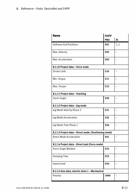
B. Reference – Festo DeviceNet and FHPP
B-13Festo P.BE-MTR-DCI-DN-EN en 1209a
Name FHPPName
SIPNU
Software End Positions 501 1, 2
Max. Velocity 502 –
Max. Acceleration 503 –
B.2.10 Project data – Force mode
Stroke Limit 510 –
Min. Torque 511 –
Max. Torque 512 –
B.2.11 Project data – Teaching
Teach Target 520 –
B.2.12 Project data – Jog mode
Jog Mode Velocity Phase 2 531 –
Jog Mode Acceleration 532 –
Jog Mode Time Phase 1 534 –
B.2.13 Project data – Direct mode: (Positioning mode)
Direct Mode Acceleration 541 –
B.2.14 Project data – Direct task (Force mode)
Force Target Window 552 –
Damping Time 553 –
Speed Limit 554 –
B.2.15 Axis data, electric drive 1 – Mechanical
Polarity 1000 –

B. Reference – Festo DeviceNet and FHPP
B-14 Festo P.BE-MTR-DCI-DN-EN en 1209a
Name FHPPName
SIPNU
Encoder Resolution 1001 1, 2
Gear Ratio 1002 1, 2
Feed Constant 1003 1, 2
Position Factor 1004 1...2
Axis Parameter 1005 1...5
B.2.16 Axis data, electric drive 1 – Homing
Offset Axis Zero Point 1010 –
Homing Method 1011 –
Homing Velocities 1012 1, 2
Homing Required 1014 –
Homing Max. Torque 1015 –
B.2.17 Axis data, electric drive 1 – Control parameters
Halt Option Code 1020 –
Fault Reaction Option Code 1021 –
Target Position Window 1022 –
Position Window Time 1023 –
Position Control Parameter Set 1024 18...23, 32
Motor Data 1025 1, 3
Drive Data 1026 1...8
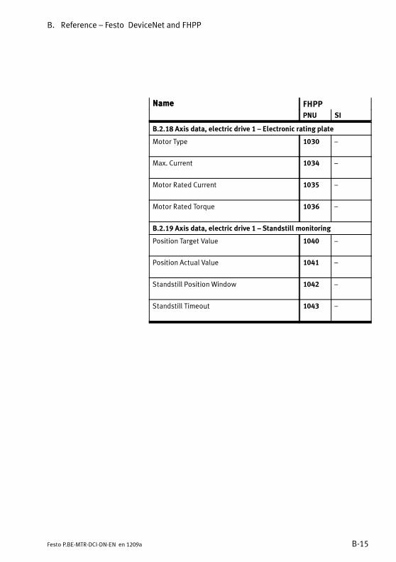
B. Reference – Festo DeviceNet and FHPP
B-15Festo P.BE-MTR-DCI-DN-EN en 1209a
Name FHPPName
SIPNU
B.2.18 Axis data, electric drive 1 – Electronic rating plate
Motor Type 1030 –
Max. Current 1034 –
Motor Rated Current 1035 –
Motor Rated Torque 1036 –
B.2.19 Axis data, electric drive 1 – Standstill monitoring
Position Target Value 1040 –
Position Actual Value 1041 –
Standstill Position Window 1042 –
Standstill Timeout 1043 –
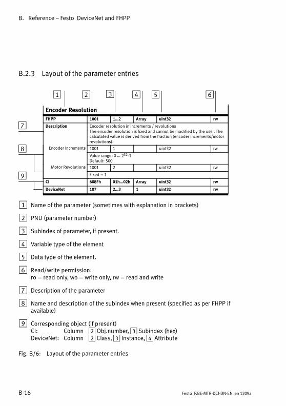
B. Reference – Festo DeviceNet and FHPP
B-16 Festo P.BE-MTR-DCI-DN-EN en 1209a
B.2.3 Layout of the parameter entries
Encoder Resolution
FHPP 1001 1...2 Array uint32 rw
Description Encoder resolution in increments / revolutionsThe encoder resolution is fixed and cannot be modified by the user. Thecalculated value is derived from the fraction (encoder increments/motorrevolutions).
Encoder Increments 1001 1 uint32 rw
Value range: 0 ... 232-1Default: 500
Motor Revolutions 1001 2 uint32 rw
Fixed = 1
CI 608Fh 01h...02h Array uint32 rw
DeviceNet 107 2...3 1 uint32 rw
1 Name of the parameter (sometimes with explanation in brackets)
2 PNU (parameter number)
3 Subindex of parameter, if present.
4 Variable type of the element
5 Data type of the element.
6 Read/write permission:ro = read only, wo = write only, rw = read and write
7 Description of the parameter
8 Name and description of the subindex when present (specified as per FHPP ifavailable)
9 Corresponding object (if present)CI: Column 2 Obj.number,3 Subindex (hex)DeviceNet: Column 2 Class,3 Instance,4 Attribute
Fig. B/6: Layout of the parameter entries
1 2 3 4 5 6
7
8
9
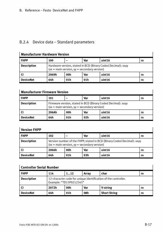
B. Reference – Festo DeviceNet and FHPP
B-17Festo P.BE-MTR-DCI-DN-EN en 1209a
B.2.4 Device data – Standard parameters
Manufacturer Hardware Version
FHPP 100 – Var uint16 ro
Description Hardware version, stated in BCD (Binary Coded Decimal): xxyy(xx = main version, yy = secondary version)
CI 2069h 00h Var uint16 ro
DeviceNet 64h 01h 01h uint16 ro
Manufacturer Firmware Version
FHPP 101 – Var uint16 ro
Description Firmware version, stated in BCD (Binary Coded Decimal): xxyy(xx = main version, yy = secondary version)
CI 206Ah 00h Var uint16 ro
DeviceNet 64h 01h 02h uint16 ro
Version FHPP
FHPP 102 – Var uint16 ro
Description Version number of the FHPP, stated in BCD (Binary Coded Decimal): xxyy(xx = main version, yy = secondary version)
CI 2066h 00h Var uint16 ro
DeviceNet 64h 01h 03h uint16 ro
Controller Serial Number
FHPP 114 1...12 Array char ro
Description 12-character code for unique identification of the controller.Example: “TD15P0212345”
CI 2072h 00h Var V-string ro
DeviceNet 64h 01h 08h Short String ro

B. Reference – Festo DeviceNet and FHPP
B-18 Festo P.BE-MTR-DCI-DN-EN en 1209a
B.2.5 Device data – Extended parameters
Manufacturer Device Name
FHPP 120 1...30 Array char ro
Description Type designation of the drive. Example: “MTR-DCI-42S-VCSC-EG14-H2DN”
CI 1008h 00h Var V-string ro
DeviceNet 64h 01h 09h Short String ro
User Device Name
FHPP 121 1...8 Array char rw
Description Device name assigned by the user.Max. 8 characters (ASCII, 7-bit). Default: “motor001”
CI 20FDh 00h Var V-string rw
DeviceNet 64h 01h 0Ah Short String ro
Drive Manufacturer
FHPP 122 1...30 Array char ro
Description Name of drive manufacturer. Fixed: “Festo AG & Co.KG”
CI 6504h 00h Var V-string ro
DeviceNet 64h 01h 0Bh Short String ro
HTTP Drive Catalogue Address
FHPP 123 1...30 Array char ro
Description Internet address of the manufacturer. Fixed: “www.festo.com”
CI 6505h 00h Var V-string ro
DeviceNet 64h 01h 0Ch Short String ro
Festo Order Number
FHPP 124 1...30 Array char ro
Description Order number of the motor unit, e. g. “533742”
CI 6503h 00h Var V-string ro
DeviceNet 64h 01h 0Dh Short String ro

B. Reference – Festo DeviceNet and FHPP
B-19Festo P.BE-MTR-DCI-DN-EN en 1209a
Device Control
FHPP 125 – Var uint8 rw
Description Activates device control of the controller via the controller interface.Corresponds to “HMI control” on the control panel and “FCT/HMI” in the FCT.0 (0x00): Control via control interface OFF,
via HMI (control panel) and FCT ON1 (0x01): Control via controller interface OFF (default)
CI 207Dh 00h Var uint8 rw
DeviceNet 64h 01h 0Eh uint8 rw
HMI Control
FHPP 126 1...4 Var uint8 ro
Description Settings for the HMI control panel (for MTR-DCI-...-H2 only)Only affects the values in the display: all parameters are stored in increments.
LCD Current(LCD voltage)
126 1 0 ro
Value range: 1...5 (0x01 ... 0x05). Default: 5
LCD Contrast 126 2 1 ro
Value range: 0...63 (0x00 ... 0x3F). Default: 0
Measuring unit 126 3 2 CI: rw
Measuring unit system for the control panel. See object 20D0h.1 (0x01): metric units of measurement (mm, mm/s, mm/s2)4 (0x04): angular degrees8 (0x08): revolutions
Scaling Factor 126 4 3 CI: rw
Number of decimal places. Fix = 2. See object 20D0h
CI 20FFh 01h...04h Array uint8 rw
DeviceNet 64h 01h 0Fh...12h uint8 rw

B. Reference – Festo DeviceNet and FHPP
B-20 Festo P.BE-MTR-DCI-DN-EN en 1209a
Data Memory Control
FHPP 127 1, 2 Array uint8 rw 1)
Description Commands for the EEPROM (non-volatile data storage)
Delete EEPROM 127 1 uint8 rw
When the object has been written, and after Power Off/On, the data in theEEPROM is reset to the factory settings.Fixed: 16 (0x10): delete data in the EEPROM and restore factory settings.Pay attention to the following note.
Save Data 127 2 uint8 rw
The data in EEPROM is overwritten with the current user-specific settings.Fixed 1 (0x01): save data
CI 20F1h 01h, 02h Array uint8 rw 1)
DeviceNet 64h 01h 14h, 15h uint8 rw 1)
1) When reading the reply “0” always occurs
NoteAll user-specific settings will be lost when the EEPROM isdeleted (except for the cycle number). The status afterdeletion corresponds to the standard factory setting.
• Always carry out initial commissioning after deleting theEEPROM.
• When the EEPROM is deleted, the field bus parametersare also reset!
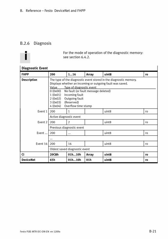
B. Reference – Festo DeviceNet and FHPP
B-21Festo P.BE-MTR-DCI-DN-EN en 1209a
B.2.6 Diagnosis
For the mode of operation of the diagnostic memory:see section 6.4.2.
Diagnostic Event
FHPP 200 1...16 Array uint8 ro
Description The type of the diagnostic event stored in the diagnostic memory.Displays whether an incoming or outgoing fault was saved.Value Type of diagnostic event0 (0x00) No fault (or fault message deleted)1 (0x01) Incoming fault2 (0x02) Outgoing fault3 (0x03) (Reserved)4 (0x04) Overflow time stamp
Event 1 200 1 uint8 ro
Active diagnostic event
Event 2 200 2 uint8 ro
Previous diagnostic event
Event ... 200 ... uint8 ro
...
Event 16 200 16 uint8 ro
Oldest saved diagnostic event
CI 20C8h 01h...10h Array uint8 ro
DeviceNet 65h 01h...10h 01h uint8 ro
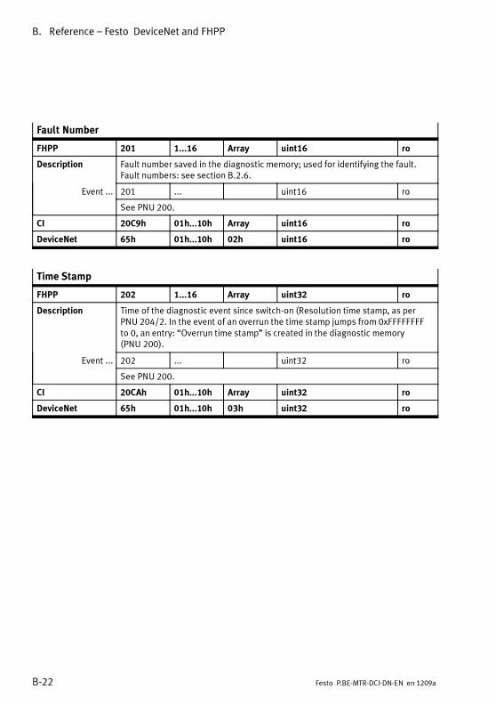
B. Reference – Festo DeviceNet and FHPP
B-22 Festo P.BE-MTR-DCI-DN-EN en 1209a
Fault Number
FHPP 201 1...16 Array uint16 ro
Description Fault number saved in the diagnostic memory; used for identifying the fault.Fault numbers: see section B.2.6.
Event ... 201 ... uint16 ro
See PNU 200.
CI 20C9h 01h...10h Array uint16 ro
DeviceNet 65h 01h...10h 02h uint16 ro
Time Stamp
FHPP 202 1...16 Array uint32 ro
Description Time of the diagnostic event since switch-on (Resolution time stamp, as perPNU 204/2. In the event of an overrun the time stamp jumps from 0xFFFFFFFFto 0, an entry: “Overrun time stamp” is created in the diagnostic memory(PNU 200).
Event ... 202 ... uint32 ro
See PNU 200.
CI 20CAh 01h...10h Array uint32 ro
DeviceNet 65h 01h...10h 03h uint32 ro

B. Reference – Festo DeviceNet and FHPP
B-23Festo P.BE-MTR-DCI-DN-EN en 1209a
Diagnostic Memory Parameter
FHPP 204 1...4 Array uint8 rw/ro
Description Configuration of the diagnostic memory.
Fault Type 204 1 uint8 rw
Incoming and outgoing faults1 (0x01): Record incoming and outgoing*) faults (default)2 (0x02): Record only incoming faults*) Outgoing fault = time when the fault was acknowledged.
Resolution 204 2 uint8 rw
Resolution time stamp.1 (0x01): Time stamp resolution 10 ms (default)2 (0x02): Time stamp resolution 1 ms
Clear Memory 204 3 uint8 rw
Deletes diagnostic memory by writing value = 1.Read will always be answered with value = 1.
Number of Entries 204 4 uint8 ro
Reads out the number of entries in the diagnostic memory.Value range: 0 ... 15 (0x00 ... 0x0F)
CI 20CCh 01h...04h Array uint8 rw/ro
DeviceNet 66h 01h 01h...04h uint8 rw/ro
Device Error
FHPP 205 – Var uint16 rw
Description Read or clear the active device fault.Read [bit 0...15]: see section 6.3, Tab. 6/6.Write 0 (0x0000): Delete the active device fault.
CI 2FF1h 00h Var uint16 rw
DeviceNet 6Ch 01h 01h uint16 rw

B. Reference – Festo DeviceNet and FHPP
B-24 Festo P.BE-MTR-DCI-DN-EN en 1209a
DeviceNet Diagnosis
FHPP 206 1...6 Array uint8 ro
Description Read the diagnostic data
Bus Status 206 1 uint8 ro
Current bus status of the DeviceNet device:0x00: “No Power / BUS-OFF”0x01: “Unrecoverable Fault”0x04, 0x05: “Minor Fault”0x10: “Operational”0x40, 0x50: “Device in Standby”
Bit Rate 206 2 uint8 ro
Current bit rate.0 (0x00): 125 kBit/s1 (0x01): 250 kBit/s2 (0x02): 500 kbps255 (0xFF): Invalid bit rate (default)
– 206 3 uint8 ro
ReservedFixed: 0 (0x00)
Address 206 4 uint8 ro
Participant address(MAC ID).Value range: 0 ... 63 (0x00 ... 0x3F)Default: 255 (0xff ) - Invalid address
Configuration 206 5 uint8 ro
Current configuration:16 (0x10): Festo FHPP Standard (8 byte I/O)17 (0x11): Festo FHPP Standard + FPC (2 x 8 byte I/O)255 (0xff ): invalid value (default)
– 206 6 uint8 ro
Reserved
CI 2FF2h 01h...06h Array uint8 ro
DeviceNet 6Dh 01h 01h...05h uint8 ro

B. Reference – Festo DeviceNet and FHPP
B-25Festo P.BE-MTR-DCI-DN-EN en 1209a
B.2.7 Process data
Local Digital Inputs
FHPP 303 – Var uint32 ro
Description Map of the digital inputsBit 0, 1: Reserved (= 0)Bit 2: Reference switch (1 = reference switch is actuated)Bit 3 ... 15: Reserved (= 0)Bit 16 ... 20: Current record number (see control byte 3)Bit 21: STOP (CCON.B1)Bit 22: ENABLE (CCON.B0)Bit 23: START (CPOS.B1)Bit 24 ... 31: Reserved (= 0)
CI 60FDh 00h Var uint32 ro
DeviceNet 67h 01h 0Ah uint32 ro
Local Digital Outputs
FHPP 304 1, 2 Array uint32 ro
Description Map of the digital outputs
Digital Outputs 304 1 uint32 ro
Bit 0...15 ReservedBit 16 MCBit 17 READYBit 18 EA_ACKBit 19 ERRORBit 20...31 Reserved
Mask 304 2 uint32 ro
Bit 0...31 Reserved
CI 60FEh 01h, 02h Array uint32 ro
DeviceNet 67h 01h 14h, 15h uint32 ro

B. Reference – Festo DeviceNet and FHPP
B-26 Festo P.BE-MTR-DCI-DN-EN en 1209a
Cycle Number
FHPP 305 – Var uint32 ro
Description Number of position set records executed, homing runs etc.Value range: 0 ... (232-1)
CI 2FFFh 00h Var uint32 ro
DeviceNet 67h 01h 1Eh uint32 ro
Keypad Status
FHPP 306 – Var uint8 ro
Description Polling of the control panel keypad (MTR-DCI-...-H2 only).Bit Value Key0 1 Enter1 2 Menu2 4 Left3 8 Right
CI 2FFEh 05h Var uint8 ro
DeviceNet 64h 01h 13h uint8 ro

B. Reference – Festo DeviceNet and FHPP
B-27Festo P.BE-MTR-DCI-DN-EN en 1209a
B.2.8 Record list
PNU 400Record numberuint8
PNU 401RCB1 1)
uint8
PNU 404Target positionint32
PNU 406speeduint32
PNU 407Accelerationuint32
0 Homing
1 ... ... ... ...
2 ... ... ... ...
... ... ... ... ...
31 ... ... ... ...
1) RCB = Record Control Byte. Defines whether positioning is relative or absolute.
Tab. B/3: Position set table structure (record list)
FHPP The record selection for reading and writing in FHPP is madevia the subindex of the PNUs 401 ... 407. Above PNU 400 theactive record for positioning or teaching is selected.
Record Number
FHPP 400 – Var uint8 rw
Description The active/selected record. Is also valid even when the drive is not in Recordselection mode (e. g. during teaching). In Record selection mode this para-meter is transferred to the cyclical I/O data.Value range: 0 ... 31 (0x00 ... 0x1F)
CI 2033h – / 00h Var uint8 rw
DeviceNet 67h 01h 20h uint8 rw

B. Reference – Festo DeviceNet and FHPP
B-28 Festo P.BE-MTR-DCI-DN-EN en 1209a
Record Control Byte 1
FHPP 401 1...32 Array uint8 rw
Description The record control byte 1 (RCB1) controls important settings for the positioningtask in Record selection mode.Bit 0: Nominal value absolute/relativeBit 1 ... 7: Reserved (= 0)Values:0 (0x00): Nominal value is absolute (default)1 (0x01): Nominal value is relative to the last nominal value / relaying value
Record 0 401 1 uint8 rw
Record control byte for position set record 0 (homing)
Record ... 401 ... uint8 rw
Record control byte for position set record 1 ... 30
Record 31 401 32 uint8 rw
Record control byte for position set record 31
CI 20EAh 01h...20h Array uint8 rw
DeviceNet 68h 01h…20h 01h uint8 rw
Record Target Position
FHPP 404 1...32 Array int32 rw
Description Target position of the position set table in increments.Value range: -231...+(231 -1) (0x80000000 ... 0x7FFFFFFF)Default: 0
Record 0 404 1 int32 rw
Nominal position value for position set record 0 (homing)
Record ... 404 ... int32 rw
Nominal position value for position set record 1 ... 30
Record 31 404 32 int32 rw
Nominal position value for position set record 31
CI 20ECh 01h...20h Array int32 rw
DeviceNet 68h 01h…20h 04h int32 rw
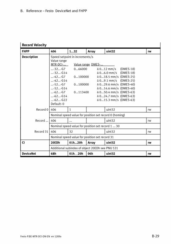
B. Reference – Festo DeviceNet and FHPP
B-29Festo P.BE-MTR-DCI-DN-EN en 1209a
Record Velocity
FHPP 406 1...32 Array uint32 rw
Description Speed setpoint in increments/sValue rangeMTR-DCI-... Value range DMES-...
...-32...-G7 0...66000 Z 0...12 mm/s (DMES-18)
...-32...-G14 Z 0...6.0 mm/s (DMES-18)
...-42...-G7 0...100000 Z 0...18.5 mm/s (DMES-25)
...-42...-G14 Z 0...9.1 mm/s (DMES-25)
...-52...-G7 0...100000 Z 0...29.6 mm/s (DMES-40)
...-52...-G14 Z 0...14.6 mm/s (DMES-40)
...-62...-G7 0...113400 Z 0...50.4 mm/s (DMES-63)
...-62...-G14 Z 0...24.7 mm/s (DMES-63)
...-62...-G22 Z 0...15.3 mm/s (DMES-63)Default: 0
Record 0 406 1 uint32 rw
Nominal speed value for position set record 0 (homing)
Record ... 406 ... uint32 rw
Nominal speed value for position set record 1 ... 30
Record 31 406 32 uint32 rw
Nominal speed value for position set record 31
CI 20EDh 01h...20h Array uint32 rw
Additional subindex of object 20EDh see PNU 531
DeviceNet 68h 01h…20h 06h uint32 rw

B. Reference – Festo DeviceNet and FHPP
B-30 Festo P.BE-MTR-DCI-DN-EN en 1209a
Record Acceleration
FHPP 407 1...32 Array uint32 rw
Description Acceleration nominal value in increments/s2. The value is only valid for Positionmode; it is ignored in Force mode.Value range:MTR-DCI-32/42: 40000...480000MTR-DCI-52/62: 40000...240000Default:MTR-DCI-32: 480000 (0x00075300)MTR-DCI-42: 480000 (0x00075300)MTR-DCI-52: 240000 (0x0003A980)MTR-DCI-62: 160000 (0x00027100)
Record 0 407 1 uint32 rw
Nominal acceleration/deceleration value for position set record 0 (homing)
Record ... 407 ... uint32 rw
Nominal acceleration/deceleration value for position set record 1...30
Record 31 407 32 uint32 rw
Nominal acceleration/deceleration value for position set record 31
CI 20EEh 01h...20h Array uint32 rw
Additional subindices of object 20EEh see PNU 532 and 541
DeviceNet 68h 01h…20h 07h uint32 rw
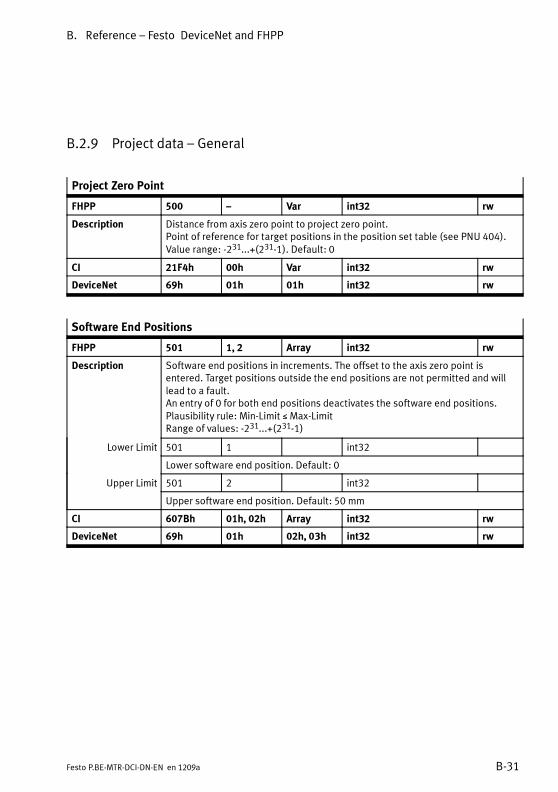
B. Reference – Festo DeviceNet and FHPP
B-31Festo P.BE-MTR-DCI-DN-EN en 1209a
B.2.9 Project data – General
Project Zero Point
FHPP 500 – Var int32 rw
Description Distance from axis zero point to project zero point.Point of reference for target positions in the position set table (see PNU 404).Value range: -231...+(231-1). Default: 0
CI 21F4h 00h Var int32 rw
DeviceNet 69h 01h 01h int32 rw
Software End Positions
FHPP 501 1, 2 Array int32 rw
Description Software end positions in increments. The offset to the axis zero point isentered. Target positions outside the end positions are not permitted and willlead to a fault.An entry of 0 for both end positions deactivates the software end positions.Plausibility rule: Min-Limit ≤ Max-LimitRange of values: -231...+(231-1)
Lower Limit 501 1 int32
Lower software end position. Default: 0
Upper Limit 501 2 int32
Upper software end position. Default: 50 mm
CI 607Bh 01h, 02h Array int32 rw
DeviceNet 69h 01h 02h, 03h int32 rw

B. Reference – Festo DeviceNet and FHPP
B-32 Festo P.BE-MTR-DCI-DN-EN en 1209a
Max. Velocity
FHPP 502 – Var uint32 rw
Description Max. permitted speed in increments/s.The specifications in Direct mode and in the position set table relate to thisvalue.Default:MTR-DCI-32: 66000 MTR-DCI-42: 100000MTR-DCI-52: 100000 MTR-DCI-62: 113400
CI 21F6h 00h Var uint32 rw
DeviceNet 69h 01h 04h uint32 rw
Max. Acceleration
FHPP 503 – Var uint32 rw
Description Max. permitted acceleration in increments/s2.The specifications in Direct mode and in the position set table relate to thisvalue.Default:MTR-DCI-32/42: 480000MTR-DCI-52/62: 240000
CI 21F7h 00h Var uint32 rw
DeviceNet 69h 01h 05h uint32 rw

B. Reference – Festo DeviceNet and FHPP
B-33Festo P.BE-MTR-DCI-DN-EN en 1209a
B.2.10 Project data – Force mode
Stroke Limit
FHPP 510 – – uint32 rw
Description Maximum permitted stroke when Force mode is active. With Force mode active,the distance between the actual position and the start positionmust not bemorethan the amount specified in this parameter. In this way you can ensure that, ifForcemode is activatedbymistake (e. g. whenworkpiece ismissing), the axiswillnot perform an uncontrolled movement. This parameter is evaluated in all con-trollermodes inwhich thepositioncontroller is notactivewhenthe status“opera-tion enabled” is set.
The monitoring can be deactivated by setting the bit RCB1.B5.
Value range: 0...4.294.967.295 inc
CI 60F6h 01h uint32 rw
DeviceNet 69h 01h 0Ah uint32 rw
Min. Torque
FHPP 511 – – uint16 rw
Description This value represents the lowest permissible torque (or force) of the motor. Thevalue is given in 1/1000 of the nominal torque (6076h / PNU 509).
Value range: 0...1000 (0x03E8)
CI 60F6h 05h uint16 rw
DeviceNet 69h 01h 0Bh uint16 rw
Max. Torque
FHPP 512 – Var uint16 rw
Description This value represents the highest permissible torque (or force) of the motor.The value is given in 1/1000 of the nominal torque (6076h / PNU 509).Value range: 0...1000 (0x03E8)
CI 6072h 00h Var uint16 rw
DeviceNet 69h 01h 0Ch uint16 rw
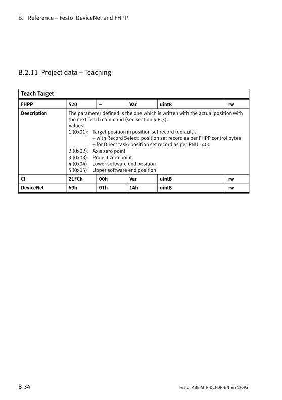
B. Reference – Festo DeviceNet and FHPP
B-34 Festo P.BE-MTR-DCI-DN-EN en 1209a
B.2.11 Project data – Teaching
Teach Target
FHPP 520 – Var uint8 rw
Description The parameter defined is the one which is written with the actual position withthe next Teach command (see section 5.6.3).Values:1 (0x01): Target position in position set record (default).
– with Record Select: position set record as per FHPP control bytes– for Direct task: position set record as per PNU=400
2 (0x02): Axis zero point3 (0x03): Project zero point4 (0x04) Lower software end position5 (0x05) Upper software end position
CI 21FCh 00h Var uint8 rw
DeviceNet 69h 01h 14h uint8 rw
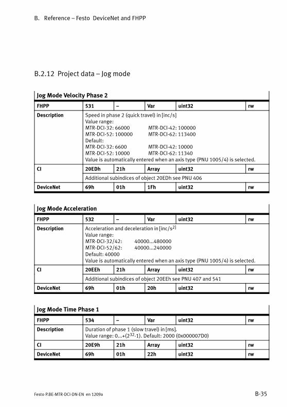
B. Reference – Festo DeviceNet and FHPP
B-35Festo P.BE-MTR-DCI-DN-EN en 1209a
B.2.12 Project data – Jog mode
Jog Mode Velocity Phase 2
FHPP 531 – Var uint32 rw
Description Speed in phase 2 (quick travel) in [inc/s]Value range:MTR-DCI-32: 66000 MTR-DCI-42: 100000MTR-DCI-52: 100000 MTR-DCI-62: 113400Default:MTR-DCI-32: 6600 MTR-DCI-42: 10000MTR-DCI-52: 10000 MTR-DCI-62: 11340Value is automatically entered when an axis type (PNU 1005/4) is selected.
CI 20EDh 21h Array uint32 rw
Additional subindices of object 20EDh see PNU 406
DeviceNet 69h 01h 1Fh uint32 rw
Jog Mode Acceleration
FHPP 532 – Var uint32 rw
Description Acceleration and deceleration in [inc/s2]
Value range:MTR-DCI-32/42: 40000...480000MTR-DCI-52/62: 40000...240000Default: 40000Value is automatically entered when an axis type (PNU 1005/4) is selected.
CI 20EEh 21h Array uint32 rw
Additional subindices of object 20EEh see PNU 407 and 541
DeviceNet 69h 01h 20h uint32 rw
Jog Mode Time Phase 1
FHPP 534 – Var uint32 rw
Description Duration of phase 1 (slow travel) in [ms].Value range: 0...+(232-1). Default: 2000 (0x000007D0)
CI 20E9h 21h Array uint32 rw
DeviceNet 69h 01h 22h uint32 rw
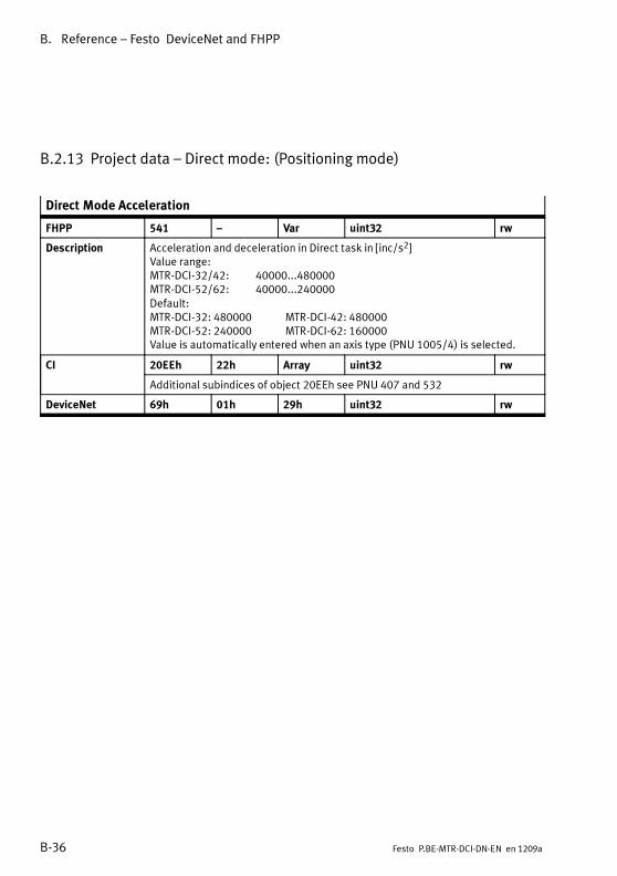
B. Reference – Festo DeviceNet and FHPP
B-36 Festo P.BE-MTR-DCI-DN-EN en 1209a
B.2.13 Project data – Direct mode: (Positioning mode)
Direct Mode Acceleration
FHPP 541 – Var uint32 rw
Description Acceleration and deceleration in Direct task in [inc/s2]Value range:MTR-DCI-32/42: 40000...480000MTR-DCI-52/62: 40000...240000Default:MTR-DCI-32: 480000 MTR-DCI-42: 480000MTR-DCI-52: 240000 MTR-DCI-62: 160000Value is automatically entered when an axis type (PNU 1005/4) is selected.
CI 20EEh 22h Array uint32 rw
Additional subindices of object 20EEh see PNU 407 and 532
DeviceNet 69h 01h 29h uint32 rw
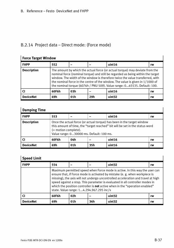
B. Reference – Festo DeviceNet and FHPP
B-37Festo P.BE-MTR-DCI-DN-EN en 1209a
B.2.14 Project data – Direct mode: (Force mode)
Force Target Window
FHPP 552 – – uint16 rw
Description The amount by which the actual force (or actual torque) may deviate from thenominal force (nominal torque) and still be regarded as being within the targetwindow. The width of the window is therefore twice the value transferred, withthe nominal force in the centre of the window. The value is given in 1/1000 ofthe nominal torque (6076h / PNU 509). Value range: 0...65535. Default: 100.
CI 60F6h 03h – uint16 rw
DeviceNet 69h 01h 29h uint32 rw
Damping Time
FHPP 553 – – uint16 rw
Description Once the actual force (or actual torque) has been in the target windowthis amount of time, the “target reached” bit will be set in the status word(= motion complete).Value range: 0...30000 ms. Default: 100 ms.
CI 60F6h 04h – uint16 rw
DeviceNet 69h 01h 35h uint16 rw
Speed Limit
FHPP 554 – – uint32 rw
Maximum permitted speed when Force mode is active. In this way the user canensure that, if Force mode is activated by mistake (e. g. when workpiece ismissing), the axis will not undergo uncontrolled acceleration and travel at highspeed against a stop. This parameter is evaluated in all controller modes inwhich the position controller is not active when in the “operation enabled”state. Value range: 1...4.294.967.295 inc/s
CI 60F6h 02h – uint32 rw
DeviceNet 69h 01h 36h uint32 rw

B. Reference – Festo DeviceNet and FHPP
B-38 Festo P.BE-MTR-DCI-DN-EN en 1209a
B.2.15 Axis parameter, electric drive 1 – Mechanical
Polarity
FHPP 1000 – Var uint8 rw
Description This parameter can be used to assign the “+/-” effect of the positioning values(vectors) to the rotational direction of the motor shaft (see section 1.6.2).Homing must then be performed again.Values:0 (0x00) = Factory setting
(“+” represents clockwise rotation)128 (0x80) = reverse direction
(“+” represents anticlockwise rotation)
CI 607Eh 00h Var uint8 rw
DeviceNet 6Bh 01h 01h uint8 rw
Encoder Resolution
FHPP 1001 1, 2 Array uint32 rw
Description Encoder resolution in [encoder increments / motor revolutions].
Encoder Increments 1001 1 uint32 rw
Values (fixed):MTR-DCI-32: 300 (0x012C)MTR-DCI-42/52/62: 500 (0x01F4)Value is automatically entered when an axis type (PNU 1005/4) is selected.
Motor Revolutions 1001 2 uint32 rw
Fixed = 1
CI 608Fh 01h, 02h Array uint32 rw
DeviceNet 6Bh 01h 02h,03h uint32 ro

B. Reference – Festo DeviceNet and FHPP
B-39Festo P.BE-MTR-DCI-DN-EN en 1209a
Gear Ratio
FHPP 1002 1, 2 Array uint32 rw
Description Relationship of the internal motor rotation to the external rotation of theMTR-DCI drive shaft. The values are permanently set for each different internalgearing (see rating plate on the MTR-DCI).Gear ratio = motor revolutions / spindle revolutions
Motor Revolutions 1002 1 uint32 rw
Internal motor revolutions (Gear ratio – numerator)Gearing G7: Fixed: 27 (0x1B)Gearing G14: Fixed: 3969 (0xF81)Gearing G22: Fixed: 1710 (0x6AE)
Shaft Revolutions 1002 2 uint32 rw
External revolutions of the drive shaft of the MTR-DCI(gear ratio – denominator).Gearing G7: Fixed: 4 (0x04)Gearing G14: Fixed: 289 (0x121)Gearing G22: Fixed: 77 (0x4D)
CI 6091h 01h, 02h Array uint32 rw
DeviceNet 6Bh 01h 04h, 05h uint32 ro
Feed Constant
FHPP 1003 1, 2 Array uint32 rw
Description The feed constant specifies the distance (=feed) that the slide moves when thedrive shaft (spindle) of the linear axis performs one revolution (feed constant =feed / spindle revolution).
Feed 1003 1 uint32 rw
Specification of feed (feed constant - counter) in [μm].When known axis types are selected on the control panel or in FCT, the valueis entered automatically.
Shaft Revolutions 1003 2 uint32 rw
Feed constant – denominator.Fixed: 1 (0x01)
CI 6092h 01h, 02h Array uint32 rw
DeviceNet 6Bh 01h 06h, 07h uint32 rw
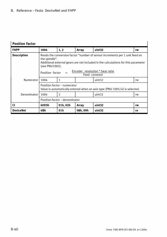
B. Reference – Festo DeviceNet and FHPP
B-40 Festo P.BE-MTR-DCI-DN-EN en 1209a
Position Factor
FHPP 1004 1, 2 Array uint32 rw
Description Reads the conversion factor “number of sensor increments per 1 unit feed onthe spindle”.Additional external gears are not included in the calculations for this parameter(see PNU1005).
Position factor =
Encoder resolution * Gear ratioFeed constant
Numerator 1004 1 uint32 rw
Position factor – numeratorValue is automatically entered when an axis type (PNU 1005/4) is selected.
Denominator 1004 2 uint32 rw
Position factor – denominator
CI 6093h 01h, 02h Array uint32 rw
DeviceNet 6Bh 01h 08h, 09h uint32 ro

B. Reference – Festo DeviceNet and FHPP
B-41Festo P.BE-MTR-DCI-DN-EN en 1209a
Axis Parameter
FHPP 1005 1...5 Array uint32 rw
Description For specifying and reading the axis parameters
Axis Length 1005 1 uint32 rw
Axis length in increments. Value range: 0...+(231-1)
Gear Numerator 1005 2 uint32 rw
If external gearing is used:Gear ratio – numeratorValue range: 0...+(231-1)
Gear Denominator 1005 3 uint32 rw
If external gearing is used:Gear ratio – denominatorValue range: 0...+(231-1)
Axis Type 1005 4 uint32 rw
Type of axisValues: 01 = DMES, 02 = DNCE, 03 = rotation deg, 04 = rotation rev, 05 =USERChanging the axis type changes the following parameters:
– Values and permissible value range:407 Record acceleration531 Jog mode speed phase 2532 Jog mode acceleration541 Direct Mode Acceleration
– Values:502 Max. velocity503 Max. acceleration1001 Encoder resolution1003 Feed constant1004 Position factor1026/3 Drive data – motor rated current1035 Motor rated current
– Permissible value range:
406 Record velocity1012 Homing velocities
Axis Size 1005 5 uint32 rw
Nominal size of the axis, in accordance with the rating plate. When known axistypes are selected on the control panel or in FCT, the value is entered automati-cally (e.g. DMES-25 = 0x19).
CI 20E2h 01h...05h Record uint32 rw
DeviceNet 6Bh 01h 0Ah... 0Eh uint32 rw
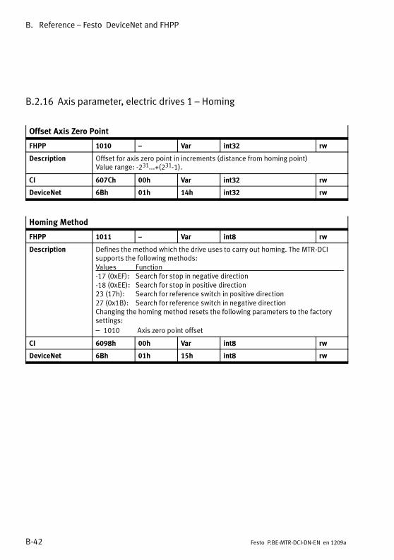
B. Reference – Festo DeviceNet and FHPP
B-42 Festo P.BE-MTR-DCI-DN-EN en 1209a
B.2.16 Axis parameter, electric drives 1 – Homing
Offset Axis Zero Point
FHPP 1010 – Var int32 rw
Description Offset for axis zero point in increments (distance from homing point)Value range: -231...+(231-1).
CI 607Ch 00h Var int32 rw
DeviceNet 6Bh 01h 14h int32 rw
Homing Method
FHPP 1011 – Var int8 rw
Description Defines the method which the drive uses to carry out homing. The MTR-DCIsupports the following methods:Values Function-17 (0xEF): Search for stop in negative direction-18 (0xEE): Search for stop in positive direction23 (17h): Search for reference switch in positive direction27 (0x1B): Search for reference switch in negative directionChanging the homing method resets the following parameters to the factorysettings:
– 1010 Axis zero point offset
CI 6098h 00h Var int8 rw
DeviceNet 6Bh 01h 15h int8 rw

B. Reference – Festo DeviceNet and FHPP
B-43Festo P.BE-MTR-DCI-DN-EN en 1209a
Homing Velocities
FHPP 1012 1, 2 Array uint32 rw
Description Speeds during homing in [inc/s].
Search REF 1012 1 uint32 rw
Speed when searching for the homing point (reference point) REF, in [inc/s]Value range:MTR-DCI-32: 200...33000 MTR-DCI-42: 200...50000MTR-DCI-52: 200...50000 MTR-DCI-62: 200...56700Default:MTR-DCI-32: 27000 MTR-DCI-42: 22400MTR-DCI-52/62: 16800
Search AZ 1012 2 uint32 rw
Speed whenmoving to the axis zero point AZ, in [inc/s]Value range:MTR-DCI-32: 200...33000 MTR-DCI-42: 200...50000MTR-DCI-52: 200...50000 MTR-DCI-62: 200...56700Default:MTR-DCI-32: 27000 MTR-DCI-42: 22400MTR-DCI-52/62: 16800
CI 6099h 01h, 02h Array uint32 rw
DeviceNet 6Bh 01h 16h, 17h uint32 rw
Homing Required
FHPP 1014 – Var uint8 rw
Description Defines whether or not homing must be carried out after switching on in orderto carry out positioning tasks.WithMTR-DCI-DN, homing must ALWAYS be carried out after switching on thelogic voltage supply!Fixed = 1: Homing must be carried out
CI 23F6h 00h Var uint8 rw
DeviceNet 6Bh 01h 19h uint8 rw
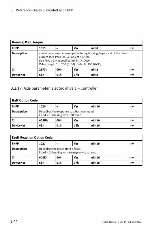
B. Reference – Festo DeviceNet and FHPP
B-44 Festo P.BE-MTR-DCI-DN-EN en 1209a
Homing Max. Torque
FHPP 1015 – Var uint8 rw
Description maximum current consumption during homing, in percent of the ratedcurrent (see PNU 1035CI object 6075h).See PNU 1034 (specification in 1/1000).Value range: 0 ... 200 (0xC8). Default: 150 (0x96)
CI 23F7h 00h Var uint8 rw
DeviceNet 6Bh 01h 1Ah uint8 rw
B.2.17 Axis parameter, electric drive 1 – Controller
Halt Option Code
FHPP 1020 – Var uint16 rw
Description Describes the response to a Halt commandFixed = 1: braking with Halt ramp
CI 605Dh 00h Var uint16 rw
DeviceNet 6Bh 01h 1Eh uint16 rw
Fault Reaction Option Code
FHPP 1021 – Var uint16 rw
Description Describes the reaction to a fault.Fixed = 2: braking with emergency stop ramp
CI 605Eh 00h Var uint16 rw
DeviceNet 6Bh 01h 1Fh uint16 rw

B. Reference – Festo DeviceNet and FHPP
B-45Festo P.BE-MTR-DCI-DN-EN en 1209a
Target Position Window
FHPP 1022 – Var uint32 rw
Description Tolerance window in increments [inc]Amount by which the current position may deviate from the target position andstill be regarded as being within the target window. The width of the window istwice the value transferred, with the target position in the centre of the window.Value range: 0 ... +(232-1). Default: 750 (0x2EE)
CI 6067h 00h Var uint32 rw
DeviceNet 6Bh 01h 20h uint32 rw
Position Window Time (adjustment time for position)
FHPP 1023 – Var uint16 rw
Description Adjustment time in milliseconds [ms]Once the actual position has been in the target position window this amount oftime, the bit “target reached” will be set in the status word (= motion com-plete).Value range: 1 ... 30000 (0x7530)Default: 100 (0x64).
CI 6068h 00h Var uint16 rw
DeviceNet 6Bh 01h 21h uint16 rw

B. Reference – Festo DeviceNet and FHPP
B-46 Festo P.BE-MTR-DCI-DN-EN en 1209a
Position Control Parameter Set
FHPP 1024 18...23, 32 Array uint16 rw
Description Control parameters.Modification is only permitted for service purposes.If necessary consult Festo.
Gain Position 1024 18 (CI: 12h) rw
Gain for position controller.Value range:MTR-DCI-32:1...100; MTR-DCI-42/52/62: 1...200Default:MTR-DCI-32:20; MTR-DCI-42:15;MTR-DCI-52:10; MTR-DCI-62:8
Gain Velocity 1024 19 (CI: 13h) rw
Gain for speed controller.Value range: MTR-DCI-32: 1...3000; MTR-DCI-42/52/62: 1...700Default: MTR-DCI-32: 2800; MTR-DCI-42/52: 600; MTR-DCI-62: 500
I-Fraction Velocity 1024 20 (CI: 14h) rw
Integral term for speed controller.Value range: 1...600Default: MTR-DCI-32: 80; MTR-DCI-42/52/62: 340
Gain Current 1024 21 (CI: 15h) rw
Gain for current controllerValue range: MTR-DCI-32: 1...1000; MTR-DCI-42/52/62: 1...800Default: MTR-DCI-32: 110; MTR-DCI-42/52/62: 150
I Fraction 1024 22 (CI:16h) rw
Integral term for current regulatorValue range: MTR-DCI-32/42/52: 0...1000Default: MTR-DCI-32: 90; MTR-DCI-42: 420; MTR-DCI-52: 350
Gain VelocityTrajectory
1024 23 (CI: 17h) rw
Gain for speed controller – trajectory generator.Value range: 1...2. Default: 1
Save Position 1024 32 (CI: 20h) rw
Saves current position in the EEPROMwhen power is switched off.Fixed = 240 (0x00F0): current position is not saved at Power-Off.
CI 60FBh 12h...17h, 20h Array uint16 rw
DeviceNet 6Bh 01h 22h...28h uint16 rw
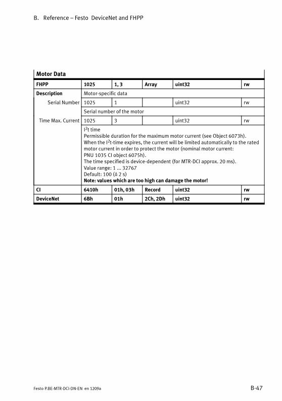
B. Reference – Festo DeviceNet and FHPP
B-47Festo P.BE-MTR-DCI-DN-EN en 1209a
Motor Data
FHPP 1025 1, 3 Array uint32 rw
Description Motor-specific data
Serial Number 1025 1 uint32 rw
Serial number of the motor
Time Max. Current 1025 3 uint32 rw
I2t timePermissible duration for the maximummotor current (see Object 6073h).When the I2t-time expires, the current will be limited automatically to the ratedmotor current in order to protect the motor (nominal motor current:PNU 1035 CI object 6075h).The time specified is device-dependent (for MTR-DCI approx. 20 ms).Value range: 1 ... 32767Default: 100 (Z 2 s)Note: values which are too high can damage the motor!
CI 6410h 01h, 03h Record uint32 rw
DeviceNet 6Bh 01h 2Ch, 2Dh uint32 rw
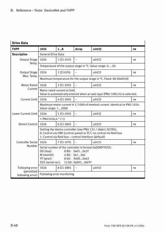
B. Reference – Festo DeviceNet and FHPP
B-48 Festo P.BE-MTR-DCI-DN-EN en 1209a
Drive Data
FHPP 1026 1...8 Array uint32 rw
Description General Drive Data
Output StageTemp.
1026 1 (CI: 01h) – uint32 rw
Temperature of the output stage in °C. Value range: 0 ... 85
Output StageMax. Temp.
1026 2 (CI:02h) – uint32 rw
Maximum temperature for the output stage in °C. Fixed: 80 (0x0050)
Motor RatedCurrent
1026 3 (CI: 03h) – uint32 rw
Motor rated current in [mA]Value is automatically entered when an axis type (PNU 1005/4) is selected.
Current Limit 1026 4 (CI: 04h) – uint32 rw
Maximummotor current in 1/1000 of nominal current. Identical to PNU 1034.Value range: 1...2000
Lower Current Limit 1026 5 (CI: 05h) – uint32 rw
= PNU1026,4 * (-1)
Device Control 1026 6 (CI: 06h) – uint32 rw
Setting the device controller (see PNU 125 / object 207Dh).0: Control via HMI (control panel) or FCT, no control via field bus1: Control via field bus – control interface (default)
Controller SerialNumber
1026 7 (CI: 07h) – uint32 rw
Serial number of the controller in format 0xDDMYYSSS:DD (day): 8 Bit: 0x01...0x1FM (month): 4 Bit: 0x1...0xCYY (year): 8 bit: 0x00...0x63SSS (serial no.): 12 bit: 0x001...0xFFF
Following error(permitted
following error)
1026 8 (CI: 08h) – uint32 rw
Following error monitoring

B. Reference – Festo DeviceNet and FHPP
B-49Festo P.BE-MTR-DCI-DN-EN en 1209a
Drive Data
CI 6510h 01h... Record ro/rw
Drive data 1) 6510h 01h...08h – uint32 rw
6510h 31h, 32h,40h, 41h,42h, 43h,A0h, 22h
– uint16, uint16,uint32, uint16,uint16, uint16,uint32, uint32
ro, roro, roro, rwro, ro
Current actualvalue
6510 45h int 16 ro
Actual current value.Note: Not available via FHPP.
Firmware Version(Firmwarenumber)
6510 A1h – uint32 ro
Firmware version, stated in BCD (Binary Coded Decimal): xxyy(xx = main version, yy = secondary version)Note: Identical to FHPP object PNU 101 (CI 206A)
DeviceNet 6Bh 01h 31h...38h uint32 ro/rw
1) Description similar to FHPP 1026/1...8
B.2.18 Axis parameter, electric drive 1 – Electronic Type plate
Motor Type
FHPP 1030 – Var uint16 rw
Description Classification of the motor. Fixed: 0x0000
CI 6402h 00h Var uint16 rw
DeviceNet 6Bh 01h 3Ch uint16 rw

B. Reference – Festo DeviceNet and FHPP
B-50 Festo P.BE-MTR-DCI-DN-EN en 1209a
Max. Current
FHPP 1034 – Var uint16 rw
Description Maximummotor current for homing in 1/1000 of the specified nominal current(see PNU 1035 / 6075h).In homing mode: Limits the motor force during homing to the stop and - in theevent of an error - protects sensitive stops during homing to a reference switch.Note:Note that the current limitation also limits the maximum possible speed andthat (higher) nominal speeds may not therefore be achieved.Value range: 1 ... 2000 (0x0001 ... 0x07D0)Default: 1500 (0x05DC)
CI 6073h 00h Var uint16 rw
DeviceNet 6Bh 01h 40h uint16 rw
Motor Rated Current
FHPP 1035 – Var uint32 rw
Description Nominal motor current in [mA]; see type plate; identical to PNU 1026/3
CI 6075h 00h Var uint32 rw
DeviceNet 6Bh 01h 41h uint32 rw
Motor Rated Torque
FHPP 1036 – Var uint32 rw
Description Nominal torque of the MTR-DCI in [mNm]
CI 6076h 00h Var uint32 rw
DeviceNet 6Bh 01h 42h uint32 rw

B. Reference – Festo DeviceNet and FHPP
B-51Festo P.BE-MTR-DCI-DN-EN en 1209a
B.2.19 Axis parameter, electric drive 1 – Standstill monitoring
Position Target Value
FHPP 1040 – Var int32 ro
Description Target position of the last positioning task, in increments.Value range: -231 ... +(231 -1)
CI 6062h 00h Var int32 ro
DeviceNet 6Bh 01h 44h int32 ro
Position Actual Value
FHPP 1041 – Var int32 ro
Description Current position of the drive in increments.Value range: -231 ... +(231 -1)
CI 6064h 00h Var int32 ro
DeviceNet 6Bh 01h 45h int32 ro
Standstill Position Window
FHPP 1042 – Var uint32 rw
Description Standstill position window in increments: Distance that the drive can moveafter “Motion Complete” before standstill monitoring reports. Value range:0...+(232-1). Default: 750 (0x02EE)
CI 2040h 00h Var uint32 rw
DeviceNet 6Bh 01h 46h uint32 rw
Standstill Timeout
FHPP 1043 – Var uint16 rw
Description Standstill monitoring time in [ms] : time for which the drive must be outside thestandstill position window before standstill monitoring responds.Value range: 0...65535 (0xFFFF). Default: 200 (0x00C8)
CI 2041h 00h Var uint16 rw
DeviceNet 6Bh 01h 47h uint16 rw

B. Reference – Festo DeviceNet and FHPP
B-52 Festo P.BE-MTR-DCI-DN-EN en 1209a

The Command Interpreter (CI)
C-1Festo P.BE-MTR-DCI-DN-EN en 1209a
Appendix C
The Command Interpreter (CI)
C. The Command Interpreter (CI)
C-2 Festo P.BE-MTR-DCI-DN-EN en 1209a
Contents
C. Reference – CANopen and CI objects C-1. . . . . . . . . . . . . . . . . . . . . . . . . . . . . .
C.1 Data transmission C-3. . . . . . . . . . . . . . . . . . . . . . . . . . . . . . . . . . . . . . . . . . . . . .
C.1.1 Procedure C-3. . . . . . . . . . . . . . . . . . . . . . . . . . . . . . . . . . . . . . . . . . . . .
C.1.2 Structure of the CI commands C-5. . . . . . . . . . . . . . . . . . . . . . . . . . . . .
C.1.3 Checking the data C-9. . . . . . . . . . . . . . . . . . . . . . . . . . . . . . . . . . . . . . .
C.2 CI Reference C-11. . . . . . . . . . . . . . . . . . . . . . . . . . . . . . . . . . . . . . . . . . . . . . . . . . .
C.2.1 Object overview (Index, Subindex) C-11. . . . . . . . . . . . . . . . . . . . . . . . . .
C.2.2 Layout of the parameter entries C-18. . . . . . . . . . . . . . . . . . . . . . . . . . . .
C.2.3 Communication Profile Area (1xxxh) C-19. . . . . . . . . . . . . . . . . . . . . . . .
C.2.4 Manufacturer Specific Profile Area (2xxxh) C-20. . . . . . . . . . . . . . . . . . .
C.2.5 Standardised Device Profile Area (6xxxh) C-26. . . . . . . . . . . . . . . . . . . .
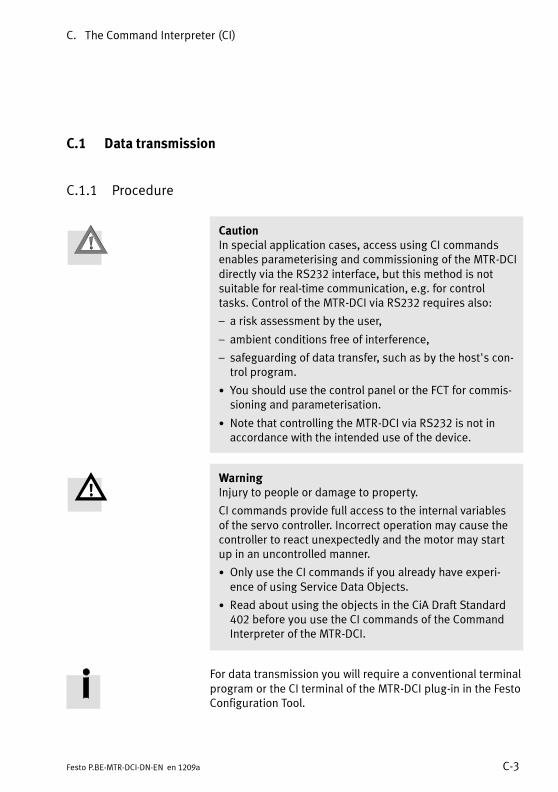
C. The Command Interpreter (CI)
C-3Festo P.BE-MTR-DCI-DN-EN en 1209a
C.1 Data transmission
C.1.1 Procedure
CautionIn special application cases, access using CI commandsenables parameterising and commissioning of the MTR-DCIdirectly via the RS232 interface, but this method is notsuitable for real-time communication, e.g. for controltasks. Control of the MTR-DCI via RS232 requires also:
– a risk assessment by the user,
– ambient conditions free of interference,
– safeguarding of data transfer, such as by the host's con-trol program.
• You should use the control panel or the FCT for commis-sioning and parameterisation.
• Note that controlling the MTR-DCI via RS232 is not inaccordance with the intended use of the device.
WarningInjury to people or damage to property.
CI commands provide full access to the internal variablesof the servo controller. Incorrect operation may cause thecontroller to react unexpectedly and the motor may startup in an uncontrolled manner.
• Only use the CI commands if you already have experi-ence of using Service Data Objects.
• Read about using the objects in the CiA Draft Standard402 before you use the CI commands of the CommandInterpreter of the MTR-DCI.
For data transmission you will require a conventional terminalprogram or the CI terminal of the MTR-DCI plug-in in the FestoConfiguration Tool.

C. The Command Interpreter (CI)
C-4 Festo P.BE-MTR-DCI-DN-EN en 1209a
Carry out the following steps:
• Connect the MTR-DCI to your PC via the RS232 port.Follow the instructions in section 3.4.
• If necessary, adapt the PC interface to the following trans-mission protocol.
Transmission protocol
Transmission speed (baud rate) 9600 bit/s
Data format Asynchronous character frame:
– 1 start bit
– 8 data bits
– no parity bit
– 1 stop bit
Tab. C/1: Specifications of the transmission protocol
• Initialise the data transfer with the following command:
Command 310D h Response 31310D h
1 <CR> 11 <CR>
• Select the commands in accordance with the object list insection C.2.1, Tab. C/7.
• Use CI commands only if you already know their effectsand if they are permitted for your MTR-DCI.
• For the syntax of the commands see appendix C.1.2.

C. The Command Interpreter (CI)
C-5Festo P.BE-MTR-DCI-DN-EN en 1209a
C.1.2 Structure of the CI commands
The commands implemented in the Command Interpreter ofthe MTR-DCI are based in respect of their content on the Ob-jects standardised by CANopen (CiA Draft Standard 402):Group 1xxx Device descriptionGroup 2xxx Festo objectsGroup 6xxx Objects as per CANopen
The complete description of all parameterisation and controlpossibilities is known as an “Object directory”. Each object isassigned a unique number (index, subindex), which is usedfor accessing that particular object.
CautionLoss of data.
The Command Interpreter (CI) contains commands whichreorganise or delete parts of the memory. Existing data isdestroyed in this process:
• It is preferable to use the FCT or the control panel forcommissioning and parameterising.
• Use the CI commands only in special cases which requiredirect access to the controller.
• Use CI commands only if you already know their effectsand if they are permitted for your MTR-DCI.
NoteIn order to restore the default settings you can, if neces-sary, delete the EEPROM via the serial interface with the CIcommand 20F1h (Data memory control) (see chapter C.1.).User-specific settings will then be lost.
• Use CI commands only if you already have experience ofService Data Objects.
• If necessary, consult Festo.

C. The Command Interpreter (CI)
C-6 Festo P.BE-MTR-DCI-DN-EN en 1209a
Access procedure
The higher-order controller sends the controller either a writecommand (WRITE) to modify a parameter in the object direc-tory, or a read command (READ) to read a parameter.
For each command the higher-order controller receives aresponse which either contains the value read or, in the caseof a write command, serves as an acknowledgement. Thetransmitted value (1, 2 or 4 data bytes) depends on the datatype of the object to be read or written.
WRITE (W) Write commands (W) transfer a value in the specified formatto the MTR-DCI. Write commands are always echoed back,character by character, from the controller of the MTR-DCI.A checksum <PS> will be inserted in front of the <CR>.
READ (R) Read commands (R) transfer a value from the MTR-DCI. Theresponse from the MTR-DCI controller contains the valueread. A checksum <PS> will be inserted in front of the <CR>.
All commands are entered as a character sequence withoutany empty spaces. A hex character corresponds to a Charcharacter in hex format.
Acc 1) Command Response
W
W 2)=IIIISS:<value><CR>=IIIISS:<value><PS><CR>
=IIIISS:<value><PS><CR>
R
R 2)?IIIISS<CR>?IIIISS<PS><CR>
=IIIISS:<value><PS><CR>
1) Access: W = write, R = read2) whenMTR-DCI checksum comparison is activated, see
section C.1.3
Tab. C/2: Syntax of a CI command/response

C. The Command Interpreter (CI)
C-7Festo P.BE-MTR-DCI-DN-EN en 1209a
Syntax Explanation
“=”, “?” Initial character for write or read commands
IIII Index as 4 hexadecimal digits
SS Subindex as 2 hexadecimal digitsIf the addressed object does not have an indexed para-meter, subindex <00> will be specified.
“:” Separating character
<Value> Data in a format determined by the data type
<PS> Checksum as 2 hexadecimal digits (see section C.1.3)
<CR> End character <Carriage Return> ($0D)
Tab. C/3: Elements of syntax of a CI command/response
Data type
The transmitted value (1, 2 or 4 data bytes as hex digits)depends on the data type of the object to be read or written.The following data types are supported:
Type Hex Format
UINT8 2H 8 bits without plus/minus sign: 0...255
INT8 8 bits with plus/minus sign: -128 ... 127
UINT16 4H 16 bits without plus/minus sign: 0 ... 65535
INT16 16 bits with plus/minus sign: -32768 ... 32767
UINT32 8H 32 bits without plus/minus sign: 0 ...(232 -1)
INT32 32 bits with plus/minus sign: -231 ... +(231 -1)
V-string corresponds to the preset string
Tab. C/4: Data types

C. The Command Interpreter (CI)
C-8 Festo P.BE-MTR-DCI-DN-EN en 1209a
NoteDirect transfer of values via the serial interface with CIcommands always takes place in the base system andrequires conversion into increments.
All parameters are always saved in increments in the con-troller and are not converted into the relevant measuringsystem until they are written or read. All physical variables(position, speed and acceleration) must be converted intoincrement values before they can be transferred.
Further information on converting can be found inchapter A.4
All values are transferred in hexadecimal figures; 1 characterrepresents 4 bits, and is known as a tetrad <Tn>. The firsttetrad transferred contains the higher-value bits of the value.Generally: tetrad <Tn> contains the bits bn...bn+3
Example: UINT8 (2H)
Dec 26
Hex 1 A
Bin 0 0 0 1 1 0 1 0
b7 b6 b5 b4 b3 b2 b1 b0
Tetrad T4 Tetrad T0

C. The Command Interpreter (CI)
C-9Festo P.BE-MTR-DCI-DN-EN en 1209a
C.1.3 Checking the data
Invalid values Transferred parameters and values are checked by the MTR-DCI before being accepted. In the case of invalid parametersor values, no error message will appear in the response, thevalues transferred are always returned.
NoteThe following applies when writing to the objects:
– Discrete values (values from a value list):A non-permitted value is not accepted, the existing validvalue is retained.
– Continuous values (values from a continuous interval):A non-permitted value is limited to the next permittedminimum or maximum value.
Recommendation:Check that values and parameters have been written correctlyby downloading the current contents of the parameter orvalue with one of the following Read commands.
Transmission error If a transmission error occurs between a higher-order con-troller and the MTR-DCI, instead on the normal response thevalue <0x00FF> is transmitted (see object 2FF0).
Possible causes:
– Incorrect initial character, separating character or emptycharacter
– Incorrect hex digit
– Incorrect value type
Checksum <PS> The higher-order controller must compare the sent commandwith the “echo” from the MTR-DCI and evaluate its checksum.Optionally, an additional checksum comparison by theMTR-DCI for received commands can also be activated(CI object 20F3h). The higher-order controller must theninsert a checksum before the termination character (CR =Carriage return).

C. The Command Interpreter (CI)
C-10 Festo P.BE-MTR-DCI-DN-EN en 1209a
If the MTR-DCI detects a checksum error then, instead of thenormal response, the value <0xFFFF> is transmitted (seeobject 2FF0h).
The checksum is calculated according to the capitalisation(uppercase/lowercase) of the command; the responsechecksum is always calculated based on uppercase letters.
Checksum <PS> W/R Command Response
Default(CI object 20F300:00)
W =IIIISS:<value><CR> =IIIISS:<value><PS><CR>
R ?IIIISS<CR> =IIIISS:<value><PS><CR>
Optionally(CI object 20F300:01)
W =IIIISS:<value><PS><CR> =IIIISS:<value><PS><CR>
R ?IIIISS><PS><CR> =IIIISS:<value><PS><CR>
W = write, R = read
Tab. C/5: Syntax of a command/response (optionally with checksum comparison by theMTR-DCI)
Checksum <PS>
Calculation Sum of all transmitted ASCII characters, reduced toone byte.W: <PS> = “=IIIISS:<value>” modulo 256R: <PS> = “?IIIISS” modulo 256
Example:Command =IIIISS:<value><CR>
=20F300:00ASCII > = 2 0 F 3 0 0 : 0 0HEX 3D+32+30+46+33+30+30+3A+30+30Sum 212hMod 256 212h mod 100h = 12hResponse =20F300:0012
Format 2 hexadecimal digits, UINT8
Tab. C/6: Checksum

C. The Command Interpreter (CI)
C-11Festo P.BE-MTR-DCI-DN-EN en 1209a
C.2 CI Reference
C.2.1 Object overview (Index, Subindex)
The following overview shows all CI objects, whereappropriate with the corresponding FHPP numbers.
NoteThe table contains an overview of the CI objects. Theobjects may be used only for certain product variants oronly with limitations (e.g. writing only for servicing pur-poses). Pay attention to the detailed description of theobjects.
You will find the descriptions of the CI objects in the followingsections (see “See” column):
– Descriptions of the corresponding PNUs as per FHPP insections B.2.4 to B.2.19,
– Descriptions of the additional CI objects from sectionC.2.3 onwards.
Name CI FHPP See
Object SI PNU
Group 1xxx
Device Type 1000h – – C.2.3
Manufacturer Device Name 1008h – 120 B.2.5
Manufacturer Hardware Version 1009h – – C.2.3
Manufacturer Software Version 100Ah – – C.2.3

C. The Command Interpreter (CI)
C-12 Festo P.BE-MTR-DCI-DN-EN en 1209a
Name SeeFHPPCIName See
PNUSIObject
Group 2xxx
Record Number 2032h 01h – C.2.4
Record Number 2033h – – C.2.4
Standstill Position Window 2040h – 1042 B.2.19
Standstill Timeout 2041h – 1043 B.2.19
Version FHPP 2066h – 102 B.2.4
Version FCT Plug-In min. 2067h – – C.2.4
Version FCT Plug-In Opt. 2068h – – C.2.4
Manufacturer Hardware Version 2069h – 100 B.2.4
Manufacturer Software Version 206Ah – 101 B.2.4
Controller Serial Number 2072h – 114 B.2.4
Device Control 207Dh – 125 B.2.5
Diagnostic Event 20C8h 01h...10h 200 B.2.6
Fault Number 20C9h 01h...10h 201 B.2.6
Time Stamp 20CAh 01h...10h 202 B.2.6
Diagnostic Memory Parameter 20CCh 01h...04h 204 B.2.6
Scaling 20D0h 01h, 02h – C.2.4
Record Table Element 20E0h 01h...05h – C.2.4

C. The Command Interpreter (CI)
C-13Festo P.BE-MTR-DCI-DN-EN en 1209a
Name CI FHPP See
Object SI PNU
Group 2xxx continued
Axis Parameter 20E2h 01h...05h 1005 B.2.15
Controller Type 20E3h – – C.2.4
Jog Mode Time Phase 1 20E9h 00h /21h
534 B.2.12
Record Control Byte 1 20EAh 01h...20h 401 B.2.8
Record Target Position 20ECh 01h...20h 404 B.2.8
Record Velocity 20EDh 01h...20h 406 B.2.8
21h 531 B.2.12
Record Acceleration 20EEh 01h...20h 407 B.2.8
21h 532 B.2.12
22h 541 B.2.13
Data Memory Control 20F1h 01h, 02h 127 B.2.5
CI_ReceiveChecksumActive 20F3h 00h – C.2.4
Password 20FAh 01h, 02h – C.2.4
Local Password 20FBh – – C.2.4
User Device Name 20FDh – 121 B.2.5
HMI Control 20FFh 01h...04h 126 B.2.5
Project Zero Point 21F4h – 500 B.2.9
Max. Velocity 21F6h – 502 B.2.9
Max. Acceleration 21F7h – 503 B.2.9

C. The Command Interpreter (CI)
C-14 Festo P.BE-MTR-DCI-DN-EN en 1209a
Name SeeFHPPCIName See
PNUSIObject
Group 2xxx continued
Teach Target 21FCh – 520 B.2.11
Homing Required 23F6h – 1014 B.2.16
Homing Max. Torque 23F7h – 1015 B.2.16
Communication Error 2FF0h – – C.2.4
Device Fault 2FF1h – 205 B.2.6
DeviceNet Diagnosis 2FF2h 01h...06h 206 B.2.6
DeviceNet Address 2FF3h – – C.2.5
DeviceNet bit rate 2FF4h – – C.2.5
DeviceNet I/O Data length 2FF5h – – C.2.5
Keypad Status 2FFEh – 306 B.2.7
Cycle Number 2FFFh – 305 B.2.7
Group 6xxx
Control word 6040h – – C.2.5
Status word 6041h – – C.2.5
Halt Option Code 605Dh – 1020 B.2.17
Fault Reaction Option Code 605Eh – 1021 B.2.17
Mode of Operation 6060h – – C.2.5

C. The Command Interpreter (CI)
C-15Festo P.BE-MTR-DCI-DN-EN en 1209a
Name SeeFHPPCIName See
PNUSIObject
Group 6xxx (continued)
Mode of Operation Display 6061h – – C.2.5
Position Target Value 6062h – 1040 B.2.19
Position Actual Value 6063h – – C.2.5
Position Actual Value 6064h – 1041 B.2.19
Position Window 6067h – 1022 B.2.17
Position Window Time 6068h – 1023 B.2.17
Velocity Demand Value 606Bh – – C.2.5
Velocity Actual Value 606Ch – – C.2.5
Target Torque 6071h – – C.2.5
Max.Torque 6072h – 512 B.2.10
Max. Current 6073h – 1034 B.2.18
Motor Rated Current 6075h – 1035 B.2.18
Motor Rated Torque 6076h – 1036 B.2.18
Torque Actual Value 6077h – – C.2.5
Current actual value 6078h – – C.2.5
Target Position 607Ah – – C.2.5
Software End Positions 607Bh 01h, 02h 501 B.2.9
Home Offset 607Ch – 1010 B.2.16

C. The Command Interpreter (CI)
C-16 Festo P.BE-MTR-DCI-DN-EN en 1209a
Name SeeFHPPCIName See
PNUSIObject
Group 6xxx (continued)
Polarity(reversal of direction)
607Eh – 1000 B.2.15
Profile Velocity 6081h – – C.2.5
Profile Acceleration 6083h – – C.2.5
Motion Profile Type 6086h – – C.2.5
Torque Slope 6087h – – C.2.5
Torque Profile Type 6088h – – C.2.5
Position Encoder Resolution 608Fh 01h, 02h 1001 B.2.15
Gear Ratio 6091h 01h, 02h 1002 B.2.15
Feed Constant 6092h 01h, 02h 1003 B.2.15
Position Factor 6093h 01h, 02h 1004 B.2.15
Homing Method 6098h – 1011 B.2.16
Homing Velocities 6099h 01h, 02h 1012 B.2.16
Stroke Limit 60F6h 01h 510 B.2.10
Speed Limit 60F6h 02h 554 B.2.14
Force Target Window 60F6h 03h 552 B.2.14
Damping Time 60F6h 04h 553 B.2.14
Min. Torque 60F6h 05h 511 B.2.10
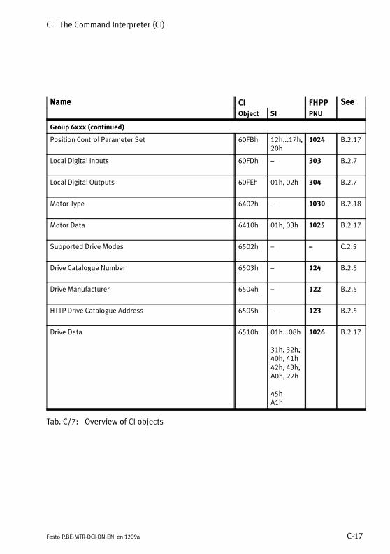
C. The Command Interpreter (CI)
C-17Festo P.BE-MTR-DCI-DN-EN en 1209a
Name SeeFHPPCIName See
PNUSIObject
Group 6xxx (continued)
Position Control Parameter Set 60FBh 12h...17h,20h
1024 B.2.17
Local Digital Inputs 60FDh – 303 B.2.7
Local Digital Outputs 60FEh 01h, 02h 304 B.2.7
Motor Type 6402h – 1030 B.2.18
Motor Data 6410h 01h, 03h 1025 B.2.17
Supported Drive Modes 6502h – – C.2.5
Drive Catalogue Number 6503h – 124 B.2.5
Drive Manufacturer 6504h – 122 B.2.5
HTTP Drive Catalogue Address 6505h – 123 B.2.5
Drive Data 6510h 01h...08h
31h, 32h,40h, 41h42h, 43h,A0h, 22h
45hA1h
1026 B.2.17
Tab. C/7: Overview of CI objects

C. The Command Interpreter (CI)
C-18 Festo P.BE-MTR-DCI-DN-EN en 1209a
C.2.2 Layout of the parameter entries
Encoder Resolution
CI 608Fh 01h...02h Array uint32 rw2
Description Encoder resolution in increments / revolutionsThe encoder resolution is fixed and cannot be modified by the user. Thecalculated value is derived from the fraction (encoder increments/motorrevolutions).
Encoder Increments 1001 1 uint32 rw2
Value range: 0 ... 232-1Default: 500
Motor Revolutions 1001 2 uint32 rw2
Fixed = 1
FHPP 1001 1...2 Array uint32 rw2
1 Name of the parameter (sometimes with explanation in brackets)
2 Object number
3 Subindices of parameter, if present (–: no subindex, simple variable)
4 Element class
5 Element variable type
6 Read/write permission: ro = read only, wo = write only, rw = read and write,rw1 = read, write at any time,rw2 = read, write during commissioning
7 Description of the parameter
8 Name and description of subindices, if present
9 Corresponding FHPP parameter, if present
Fig. C/7: Layout of the parameter entries
1 2 3 4 5 6
7
8
9

C. The Command Interpreter (CI)
C-19Festo P.BE-MTR-DCI-DN-EN en 1209a
C.2.3 Communication Profile Area (1xxxh)
Device Type
CI 1000h 00h Var uint32 ro
Description Classification of device type and functionality.Bit: 31 ... 16 15 ... 0
Additional information Device Profile NumberValue: 301 (0x012d)Additional information:0 (0x0000) – not used
Manufacturer Hardware Version
CI 1009h 00h Var V-string ro
Description Hardware version in the format = “V xx.yy” (xx = main version, yy = secondaryversion)
See PNU 100 / object 2069h
Manufacturer Software Version
CI 100Ah 00h Var V-string ro
Description Firmware version in the format = “V xx.yy” (xx = main version, yy = secondaryversion)
See PNU 101 / object 206Ah

C. The Command Interpreter (CI)
C-20 Festo P.BE-MTR-DCI-DN-EN en 1209a
C.2.4 Manufacturer Specific Profile Area (2xxxh)
Record Number
CI 2032h 01h Array 1) uint8 rw
1) Pseudo-array due to compatibility
Description For selecting a position set record via the record number.The record number is saved as the target for write and read operations on thefollowing objects:
– object 20E0/01h...05h: Record Table Element
– or objects 607Ah, 6081h, 6083h
There is a direct correlation with object 2033h (PNU 401).
Record Number 2032h 01h uint8 rw
Reading or writing a record number.Values:0 (0x00): Direct position record1 (0x00): RS232 position record (FCT record)2 (0x02): Homing (position set record 0)3 (0x03): Position set record 1 (default)4 (0x04): Position set record 2... Position set record ...33 (0x21): Position set record 31
Version FCT Plug-In Min.
CI 2067h 00h Var V-string r
Description Minimum version of FCT MTR-DCI plug-in required for commissioning the MTR-DCI with the firmware version being used.Format = “xx.yy” (xx = main version, yy = secondary version)
Version FCT Plug-In Opt.
CI 2068h 00h Var V-string r
Description Version of FCT MTR-DCI plug-in optimally suited for commissioning of the MTR-DCI with the firmware version being used.Format = “xx.yy” (xx = main version, yy = secondary version)

C. The Command Interpreter (CI)
C-21Festo P.BE-MTR-DCI-DN-EN en 1209a
Scaling
CI 20D0h 01h, 02h Array uint8 rw/ro
Description Settings for the HMI control panel (for MTR-DCI-...-H2 only)Only affects the values in the display: All parameters are stored in increments.
Measuring Unit 20D0h 01h uint8 rw
Defines a system of measurement for the control panel.1 (0x01): metric units of measurement (mm, mm/s, mm/s2)4 (0x04): angular degrees8 (0x08): revolutionsSee PNU126/20FFh.
Scaling Factor 20D0h 02h uint8 ro
Number of decimal places. Fixed = 2. See PNU126/20FFh.

C. The Command Interpreter (CI)
C-22 Festo P.BE-MTR-DCI-DN-EN en 1209a
Record Table Element
CI 20E0h 01h ... 05h Record uint16, int32 rw
Description For editing the entries in the position set table:1. Select line (= record number) with object 2032h.2. Select column via subindex 20E0h: 01...04
20E0/01 20E0/02V
20E0/03 20E0/04
RecordNumber
Pos-setMode
TargetPosition
ProfileVelocity
ProfileAcc.
02
2032h 03 <1> <...> ... ...
...
The values are only saved in the position table with this command; no move-ment is made.
Positioning Mode 20E0h 01h uint16 rw
Positioning mode (record control word). Values:0 (0x0000): Absolute positioning (default)1 (0x0001): Relative positioning
Target Position 20E0h 02h int32 rw
Target position in increments (Z object 607Ah).Value range: -231...+(231 -1) (0x80000000 ... 0x7FFFFFFF). Default: 0
Velocity 20E0h 03h int32 rw
Positioning speed in increments/s (Z object 6081h).Value range (depending on axis type, see object 20E2/04):MTR-DCI-... Value range
...-32...-G7 (G14) 0...66000 DMES-18: Z 0...12 (6) mm/s
...-42...-G7 (G14) 0...100000 DMES-25: Z 0...18.5 (9.1) mm/s
...-52...-G7 (G14) 0...100000 DMES-40: Z 0...29.6 (14.6) mm/s
...-62...-G7 (G14) (G22) 0...113400 DMES-63: Z 0...50.4 (24.7) (15.3) mm/s
Acceleration 20E0h 04h int32 rw
Acceleration in increments/s2 (Z object 6083h).Value range (depending on axis type, see object 20E2/04):MTR-DCI-32/42: 40000...480000 MTR-DCI-52/62: 40000...240000Default:MTR-DCI-32/42: 480000 (0x00075300)MTR-DCI-52: 240000 (0x0003A980)MTR-DCI-62: 160000 (0x00027100)
Object 20E0 accesses some of the same parameters as the corresponding objects 607Ah, 6081h,6083h, 6084h or objects 20EAh to 20EFh. Different data types are converted accordingly whenwriting and reading.

C. The Command Interpreter (CI)
C-23Festo P.BE-MTR-DCI-DN-EN en 1209a
Controller Type
CI 20E3h – Var uint8 rw
Description Type of controller.Values: 0 = without display; 1 = with display.
CI_ReceiveChecksumActive
CI 20F3h 00h Var uint8 rw
Description Enable checksum checking of received CI telegrams, see section C.1.2,Tab. C/2.Values:0 (0x00): disabled (default)1 (0x01): enabledExample: deactivate checksum: “=20F300:0012” (12 = checksum)
Password
CI 20FAh 01h, 02h Array V-string rw/ro
Description For managing the FCT password, entering the super password.
FCT Password 20FAh 01h V-string rw
Password for the FCT softwareValue: <........> (fixed: 8 characters, ASCII, 7-bit)Default: <00000000> (status upon delivery and after reset)
Super Password 20FAh 02h V-string ro
For entering the super password.Resets all passwords (FCT password and HMI password, object 20FB). ContactFesto Service if you require the super password.
Local Password
CI 20FBh 00h Var V-string rw
Description For managing the (local) HMI password to enable particular functions that canbe carried out via the control panel.Value: <........> (fixed: 8 characters, ASCII, 7-bit)
Only the first 3 characters are evaluated.Default: <00000000> (status upon delivery and after reset)
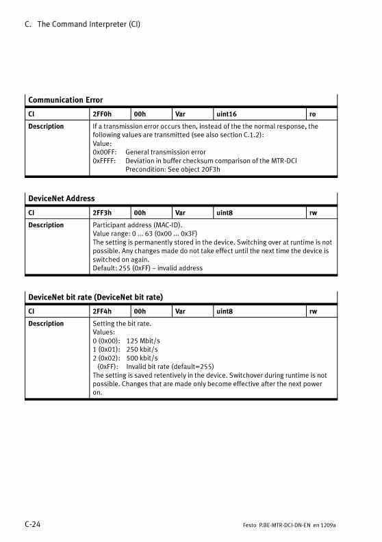
C. The Command Interpreter (CI)
C-24 Festo P.BE-MTR-DCI-DN-EN en 1209a
Communication Error
CI 2FF0h 00h Var uint16 ro
Description If a transmission error occurs then, instead of the the normal response, thefollowing values are transmitted (see also section C.1.2):Value:0x00FF: General transmission error0xFFFF: Deviation in buffer checksum comparison of the MTR-DCI
Precondition: See object 20F3h
DeviceNet Address
CI 2FF3h 00h Var uint8 rw
Description Participant address (MAC-ID).Value range: 0 ... 63 (0x00 ... 0x3F)The setting is permanently stored in the device. Switching over at runtime is notpossible. Any changes made do not take effect until the next time the device isswitched on again.Default: 255 (0xFF) – invalid address
DeviceNet bit rate (DeviceNet bit rate)
CI 2FF4h 00h Var uint8 rw
Description Setting the bit rate.Values:0 (0x00): 125 Mbit/s1 (0x01): 250 kbit/s2 (0x02): 500 kbit/s(0xFF): Invalid bit rate (default=255)
The setting is saved retentively in the device. Switchover during runtime is notpossible. Changes that are made only become effective after the next poweron.

C. The Command Interpreter (CI)
C-25Festo P.BE-MTR-DCI-DN-EN en 1209a
DeviceNet I/O Data length
CI 2FF5h 00h Var uint8 rw
Description Protocol (data/device profile).Values:0 (0x00): Festo FHPP Standard (8 byte I/O) = default1 (0x01): Festo FHPP Standard + FPC (2 x 8 byte I/O)
If the FPC is not required during operation (e.g. because parameter changes areperformed using Explicit Messaging) then the data width can be reduced to8 bytes. This switches off the FPC and optimises the bus transmissions. Thesetting is permanently stored in the device. Switching over at runtime is notpossible. Any changes made do not take effect until the next time the device isswitched on again.

C. The Command Interpreter (CI)
C-26 Festo P.BE-MTR-DCI-DN-EN en 1209a
C.2.5 Standardised Device Profile Area (6xxxh)
Control word
CI 6040h 00h Var uint16 rw
Description For modifying the current controller status or triggering an action. Statuschanges triggered by the control word must be read back via the status word.Only after the requested status has been read from the status word may afurther command be written via the control word.For values see Tab. C/8
Bit Value Description
0 0x0001 Switch on Controlling the state transitions.These bits are evaluated together!1 0x0002 Enable Voltage
2 0x0004 Quick Stop – low-active!
3 0x0008 Enable Operation
4 0x0010 Mode-specific (object 6060h):
– Homing mode: Homing Operation Start
– Profile Position Mode / Torque Mode: New Setpoint (move to position)
5 0x0020 Mode-specific (object 6060h):
– Homing Mode: reserved (set to 0)
– Profile Position Mode: reserved (change_set_immediately in recordselection and direct mode is not supported)
– Profile Torque Mode: =1: With stroke limitation; =0: Without stroke
limitation
6 0x0040 Mode-specific (object 6060h):
– Profile Position Mode: absolute / relative
– Homing Mode: reserved (set to 0)
– Profile Torque Mode: reserved (set to 1)
7 0x0080 Fault Reset
8 0x0100 Halt as per Halt Option Code – object 605Dh.
9 0x0200 Reserved (= 0)
10 0x0400 Reserved (= 0)
11 0x0800 Jog positive: Move while set (as with FHPP CPOS.B3)
12 0x1000 Jog negative: Move while set (as with FHPP CPOS.B4)
13 0x2000 Teach: Apply current value
14 0x4000 Reserved (= 0)
15 0x8000 Reserved (= 0)
Tab. C/8: Description of Control Word

C. The Command Interpreter (CI)
C-27Festo P.BE-MTR-DCI-DN-EN en 1209a
Status word
CI 6041h 00h Var uint16 ro
Description For reading the current controller/regulator status.
State machine description: see section 5.8
For values see Tab. C/9.
Bit Value Description
0 0x0001 Ready to switch on Bits 0 ... 3, 5 and 6 show the status of the device(x ... irrelevant for this status)Value (binary) Statusxxxx xxxx x0xx 0000 Not ready to switch onxxxx xxxx x1xx 0000 Switch on disabledxxxx xxxx x01x 0001 Ready to switch onxxxx xxxx x01x 0011 Switched onxxxx xxxx x01x 0111 Operation enabledxxxx xxxx x00x 0111 Quick stop activexxxx xxxx x0xx 1111 Fault reaction activexxxx xxxx x0xx 1000 Fault
1 0x0002 Switched on
2 0x0004 Operation enabled
3 0x0008 Fault
4 0x0010 Voltage enabled
5 0x0020 Quick Stop
6 0x0040 Switch on disabled
7 0x0080 Warning (simple fault which does not require an emergency stop)
8 0x0100 Drive moves (corresponds to bit 4 of SPOS in FHPP)
9 0x0200 Master control (corresponds to bit 5 of SCON in FHPP)
10 0x0400 Target reached (see also objects 6067 and 6068)
11 0x0800 Internal Limit active
12 0x1000 Depends on operation mode (object 6060):
– Profile Position mode: Setpoint Acknowledge
– Homing mode: Homing Attained
– Profile Torque Mode: is running
13 0x2000 Depends on operation mode (object 6060):
– Profile Position mode: Following Error
– Homing mode: Homing Error
– Profile Torque Mode: stroke limit reached
14 0x4000 Teach acknowledge (corresponds to bit 3 of SPOS in FHPP)
15 0x8000 Homing performed (corresponding to bit 7 of SPOS in FHPP)
Tab. C/9: Description of Status Word

C. The Command Interpreter (CI)
C-28 Festo P.BE-MTR-DCI-DN-EN en 1209a
Modes of Operation
CI 6060h 00h Var int8 rw
Description Set the controller operation mode.Values:-2 (0xFE): Demo mode (fixed sequence)1 (0x01): Profile Position Mode (default, position controller with positioningmode)3 (0x03): Reserved4 (0x04): Profile Torque Mode (Force mode)6 (0x06): Homing Mode
Modes of Operation Display
CI 6061h 00h Var int8 ro
Description Read current controller operation mode.For values, see object 6060h.
Position Actual Value
CI 6063h 00h Var int32 ro
Description Current position of the drive in increments.Value range: -231 ... +(231 -1)Value is only updated at the end of a controller cycle.
Velocity Demand Value
CI 606Bh 00h Var int32 ro
Description Current nominal speed value of speed regulator in increments/s.Value range: -231 ... +(231 -1)
Velocity Actual Value
CI 606Ch 00h Var int32 ro
Description Current actual speed value of speed regulator in increments/s.Value range: -231 ... +(231 -1)
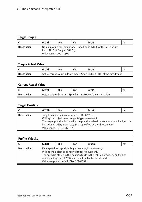
C. The Command Interpreter (CI)
C-29Festo P.BE-MTR-DCI-DN-EN en 1209a
Target Torque
CI 6071h 00h Var int32 ro
Description Nominal value for Force mode. Specified in 1/000 of the rated value(see PNU 512/ object 6072h).Value range: 200...1500
Torque Actual Value
CI 6077h 00h Var int32 ro
Description Actual torque value in force mode. Specified in 1/000 of the rated value
Current Actual Value
CI 6078h 00h Var int32 ro
Description Actual value of current. Specified in 1/000 of the rated value
Target Position
CI 607Ah 00h Var int32 rw
Description Target position in increments. See 20E0/02h.Writing the object does not yet trigger movement.The target position is stored in the position table in the column provided, on theline addressed by object 2032h or specified by the direct mode.Value range: -231 ... +(231 -1)
Profile Velocity
CI 6081h 00h Var uint32 rw
Description Final speed for a positioning procedure, in increment/s.Writing the object does not yet trigger movement.The speed is stored in the position table in the column provided, on the lineaddressed by object 2032h or specified by the direct mode.Value range and default: See 20E0/03h.

C. The Command Interpreter (CI)
C-30 Festo P.BE-MTR-DCI-DN-EN en 1209a
Profile Acceleration
CI 6083h 00h Var uint32 rw
Description Acceleration for a positioning movement in increments/s2.See 20E0/04hWriting the object does not yet trigger movement.The acceleration is stored in the position table in the column provided, on theline addressed by object 2032h or specified by the direct mode.Value range and default: See 20E0/04h.
Motion Profile Type
CI 6086h 00h Var int16 rw
Description Type of the mode of acceleration ramp (linear, sin etc.).Fixed = -1 (0xFFFF): Linear ramp
Torque Slope
CI 6087h 00h Var uint32 r
Description Rate of change in torque (or force)Unit of measurement: 1/1000 of the nominal (rated) torque (6076h) persecondFixed: 10000 (0x2710)
Torque Profile Type
CI 6088h 00h Var uint32 r
Description Type of profile used for a change in torque.Fixed: 0x0000 - Linear ramp
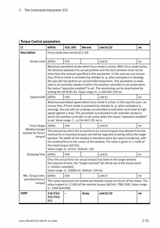
C. The Command Interpreter (CI)
C-31Festo P.BE-MTR-DCI-DN-EN en 1209a
Torque Control parameters
CI 60F6h 01h, 05h Record uint16/32 rw
Description Force mode (see section B.2.10)
Stroke Limit 60F6h 01h uint32 rw
Maximum permitted stroke when Force mode is active. With Force mode active,the distance between the actual position and the start position must not bemore than the amount specified in this parameter. In this way you can ensurethat, if Force mode is activated by mistake (e. g. when workpiece is missing),the axis will not perform an uncontrolled movement. This parameter is evalu-ated in all controller modes in which the position controller is not active whenthe status “operation enabled” is set. The monitoring can be deactivated bysetting the bit RCB1.B5. Value range: 0...4.294.967.295 inc
Speed Limit 60F6h 02h uint32 rw
Maximum permitted speed when Force mode is active. In this way the user canensure that, if Force mode is activated by mistake (e. g. when workpiece ismissing), the axis will not undergo uncontrolled acceleration and travel at highspeed against a stop. This parameter is evaluated in all controller modes inwhich the position controller is not active when the status “operation enabled”is set. Value range: 1...4.294.967.295 inc/s
Force TargetWindow (target
window for force/torque)
60F6h 03h uint16 rw
The amount by which the actual force (or actual torque) may deviate from thenominal force (nominal torque) and still be regarded as being within the targetwindow. The width of the window is therefore twice the value transferred, withthe nominal force in the centre of the window. The value is given in 1/1000 ofthe rated torque (6076h).Value range: 0...65535. Default: 100.
Damping Time 60F6h 04h uint16 rw
Once the actual force (or actual torque) has been in the target windowthis amount of time, the “target reached” bit will be set in the status word(= motion complete).Value range: 0...30000 ms. Default: 100 ms.
Min. Torque (min.permitted force/
torque)
60F6h 04h uint32 rw
This value represents the lowest permissible torque (or force) of the motor. Thevalue is given in 1/1000 of the nominal torque (6076h / PNU 509). Value range:0...1000 (0x03E8).
FHPP 510/554/552/553/511
– Array uint16/32 rw

C. The Command Interpreter (CI)
C-32 Festo P.BE-MTR-DCI-DN-EN en 1209a
Supported Drive Modes
CI 6502h 00h Var uint32 ro
Description Drive modes supported. Fixed = 29h (41d)Bit 0: Profile position modeBit 1: Reserved (Velocity mode)Bit 2: Reserved (Profile velocity mode)Bit 3: Profile torque modeBit 4: ReservedBit 5: Homing modeBit 6: Reserved (Interpolated positioning mode)Bits 7...31: Reserved

Index
D-1Festo P.BE-MTR-DCI-DN-EN en 1209a
Appendix D
Index

D. Index
D-2 Festo P.BE-MTR-DCI-DN-EN en 1209a

D. Index
D-3Festo P.BE-MTR-DCI-DN-EN en 1209a
A
Absolute 5-18, 5-42, B-29. . . . . . . . . . . . . . . . . . . . . . . . . . . . .
Access procedure C-6. . . . . . . . . . . . . . . . . . . . . . . . . . . . . . . . .
Axis XVII, 1-3, 1-14. . . . . . . . . . . . . . . . . . . . . . . . . . . . . . . . . . .Axis type 5-10. . . . . . . . . . . . . . . . . . . . . . . . . . . . . . . . . . . . .Parameterisation 5-16. . . . . . . . . . . . . . . . . . . . . . . . . . . . . .
Axis zero point XVII, 1-19, 5-16, B-43. . . . . . . . . . . . . . . . . . . .
B
Bit rate 5-22. . . . . . . . . . . . . . . . . . . . . . . . . . . . . . . . . . . . . . . .
Bus parameter, Setting 4-23, 5-21. . . . . . . . . . . . . . . . . . . . . .
Bus termination 3-16. . . . . . . . . . . . . . . . . . . . . . . . . . . . . . . . .
C
Cable 1-14, 3-5. . . . . . . . . . . . . . . . . . . . . . . . . . . . . . . . . . . . . .Field bus 3-17. . . . . . . . . . . . . . . . . . . . . . . . . . . . . . . . . . . . .
CCON 5-37. . . . . . . . . . . . . . . . . . . . . . . . . . . . . . . . . . . . . . . . . .
CDIR 5-39. . . . . . . . . . . . . . . . . . . . . . . . . . . . . . . . . . . . . . . . . .
CI XVI, C-3. . . . . . . . . . . . . . . . . . . . . . . . . . . . . . . . . . . . . . . . . .
Classes 1-9, 1-10. . . . . . . . . . . . . . . . . . . . . . . . . . . . . . . . . . . .
CommissioningAt the Fieldbus 5-28. . . . . . . . . . . . . . . . . . . . . . . . . . . . . . . .Procedure 5-5. . . . . . . . . . . . . . . . . . . . . . . . . . . . . . . . . . . . .with the control panel 5-8. . . . . . . . . . . . . . . . . . . . . . . . . . .With the Festo Configuration Tool (FCT) 5-24. . . . . . . . . . . .
Components 1-14. . . . . . . . . . . . . . . . . . . . . . . . . . . . . . . . . . . .
Connections 3-4. . . . . . . . . . . . . . . . . . . . . . . . . . . . . . . . . . . . .

D. Index
D-4 Festo P.BE-MTR-DCI-DN-EN en 1209a
Control panel 4-4. . . . . . . . . . . . . . . . . . . . . . . . . . . . . . . . . . . .Accessing the main menu 4-6. . . . . . . . . . . . . . . . . . . . . . . .Button function (overview) 4-5. . . . . . . . . . . . . . . . . . . . . . .Menu system 4-6. . . . . . . . . . . . . . . . . . . . . . . . . . . . . . . . . .Menu commands (overview) 4-7. . . . . . . . . . . . . . . . . . . . . .Selecting a menu command 4-6. . . . . . . . . . . . . . . . . . . . . .
Controller XVII, 1-3, 3-15. . . . . . . . . . . . . . . . . . . . . . . . . . . . . .
Coupling 1-14. . . . . . . . . . . . . . . . . . . . . . . . . . . . . . . . . . . . . . .
CPOS 5-38. . . . . . . . . . . . . . . . . . . . . . . . . . . . . . . . . . . . . . . . . .
D
Data profile 1-11. . . . . . . . . . . . . . . . . . . . . . . . . . . . . . . . . . . . .
Demo mode 5-19. . . . . . . . . . . . . . . . . . . . . . . . . . . . . . . . . . . .
Device connection 5-92. . . . . . . . . . . . . . . . . . . . . . . . . . . . . . .
Device control 4-24, 5-8, 5-26. . . . . . . . . . . . . . . . . . . . . . . . .
Device profile 1-8. . . . . . . . . . . . . . . . . . . . . . . . . . . . . . . . . . . .
DeviceNet 1-6, 5-29. . . . . . . . . . . . . . . . . . . . . . . . . . . . . . . . . .Classes B-3. . . . . . . . . . . . . . . . . . . . . . . . . . . . . . . . . . . . . . .Object directory B-3. . . . . . . . . . . . . . . . . . . . . . . . . . . . . . . .
Diagnosis 4-8, B-13. . . . . . . . . . . . . . . . . . . . . . . . . . . . . . . . . .Fault messages 6-7. . . . . . . . . . . . . . . . . . . . . . . . . . . . . . . . .Overview 6-3. . . . . . . . . . . . . . . . . . . . . . . . . . . . . . . . . . . . . .via Fieldbus 6-12. . . . . . . . . . . . . . . . . . . . . . . . . . . . . . . . . . .
Diagnostic memory 6-13. . . . . . . . . . . . . . . . . . . . . . . . . . . . . .
Dimensional reference system 1-20. . . . . . . . . . . . . . . . . . . . .
Dimensions 2-4. . . . . . . . . . . . . . . . . . . . . . . . . . . . . . . . . . . . . .
Direct Task 1-11, 5-32, 5-36, 5-68. . . . . . . . . . . . . . . . . . . . . . .
Direction of motor rotation 1-21. . . . . . . . . . . . . . . . . . . . . . . .
Drive XVII, 1-3. . . . . . . . . . . . . . . . . . . . . . . . . . . . . . . . . . . . . . .
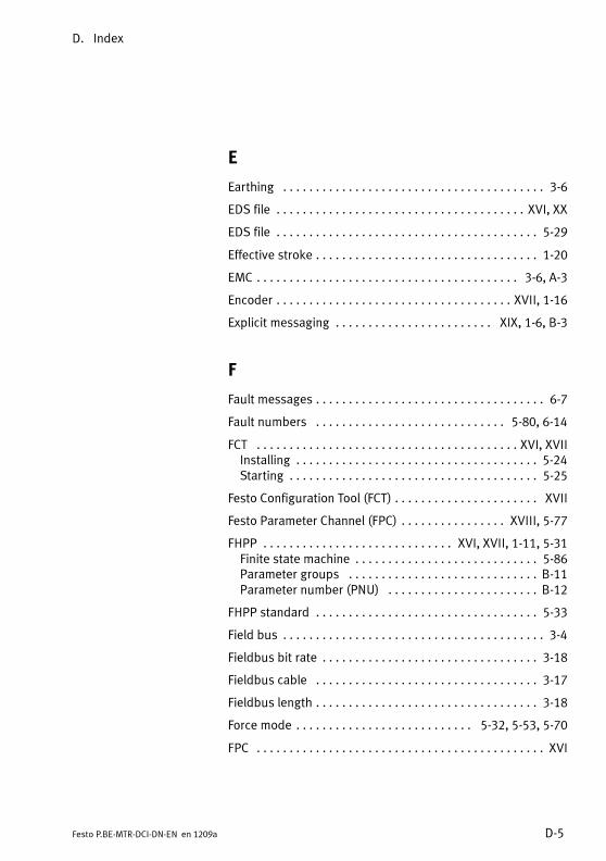
D. Index
D-5Festo P.BE-MTR-DCI-DN-EN en 1209a
E
Earthing 3-6. . . . . . . . . . . . . . . . . . . . . . . . . . . . . . . . . . . . . . . .
EDS file XVI, XX. . . . . . . . . . . . . . . . . . . . . . . . . . . . . . . . . . . . . .
EDS file 5-29. . . . . . . . . . . . . . . . . . . . . . . . . . . . . . . . . . . . . . . .
Effective stroke 1-20. . . . . . . . . . . . . . . . . . . . . . . . . . . . . . . . . .
EMC 3-6, A-3. . . . . . . . . . . . . . . . . . . . . . . . . . . . . . . . . . . . . . . .
Encoder XVII, 1-16. . . . . . . . . . . . . . . . . . . . . . . . . . . . . . . . . . . .
Explicit messaging XIX, 1-6, B-3. . . . . . . . . . . . . . . . . . . . . . . .
F
Fault messages 6-7. . . . . . . . . . . . . . . . . . . . . . . . . . . . . . . . . . .
Fault numbers 5-80, 6-14. . . . . . . . . . . . . . . . . . . . . . . . . . . . .
FCT XVI, XVII. . . . . . . . . . . . . . . . . . . . . . . . . . . . . . . . . . . . . . . .Installing 5-24. . . . . . . . . . . . . . . . . . . . . . . . . . . . . . . . . . . . .Starting 5-25. . . . . . . . . . . . . . . . . . . . . . . . . . . . . . . . . . . . . .
Festo Configuration Tool (FCT) XVII. . . . . . . . . . . . . . . . . . . . . .
Festo Parameter Channel (FPC) XVIII, 5-77. . . . . . . . . . . . . . . .
FHPP XVI, XVII, 1-11, 5-31. . . . . . . . . . . . . . . . . . . . . . . . . . . . .Finite state machine 5-86. . . . . . . . . . . . . . . . . . . . . . . . . . . .Parameter groups B-11. . . . . . . . . . . . . . . . . . . . . . . . . . . . .Parameter number (PNU) B-12. . . . . . . . . . . . . . . . . . . . . . .
FHPP standard 5-33. . . . . . . . . . . . . . . . . . . . . . . . . . . . . . . . . .
Field bus 3-4. . . . . . . . . . . . . . . . . . . . . . . . . . . . . . . . . . . . . . . .
Fieldbus bit rate 3-18. . . . . . . . . . . . . . . . . . . . . . . . . . . . . . . . .
Fieldbus cable 3-17. . . . . . . . . . . . . . . . . . . . . . . . . . . . . . . . . .
Fieldbus length 3-18. . . . . . . . . . . . . . . . . . . . . . . . . . . . . . . . . .
Force mode 5-32, 5-53, 5-70. . . . . . . . . . . . . . . . . . . . . . . . . . .
FPC XVI. . . . . . . . . . . . . . . . . . . . . . . . . . . . . . . . . . . . . . . . . . . .

D. Index
D-6 Festo P.BE-MTR-DCI-DN-EN en 1209a
H
HMI (see device control) XVIII. . . . . . . . . . . . . . . . . . . . . . . . . .
Homing XVIII, 5-14, 5-91. . . . . . . . . . . . . . . . . . . . . . . . . . . . . .Current limitation 5-11. . . . . . . . . . . . . . . . . . . . . . . . . . . . . .Discontinuing 5-15. . . . . . . . . . . . . . . . . . . . . . . . . . . . . . . . .Homing point XVIII, 1-19. . . . . . . . . . . . . . . . . . . . . . . . . . . .Method XVIII. . . . . . . . . . . . . . . . . . . . . . . . . . . . . . . . . . . . . .Parameter 4-19, B-43. . . . . . . . . . . . . . . . . . . . . . . . . . . . . . .Reference switch XVIII, 1-14, 3-4, 3-13. . . . . . . . . . . . . . . .Starting 4-14, 5-14. . . . . . . . . . . . . . . . . . . . . . . . . . . . . . . . .
Homing methodFixed stop 1-24. . . . . . . . . . . . . . . . . . . . . . . . . . . . . . . . . . . .Reference switch 1-25. . . . . . . . . . . . . . . . . . . . . . . . . . . . . .
Homing mode XVIII. . . . . . . . . . . . . . . . . . . . . . . . . . . . . . . . . . .
Homing Mode (see Homing) 1-16. . . . . . . . . . . . . . . . . . . . . . .
I
I/F 3-16. . . . . . . . . . . . . . . . . . . . . . . . . . . . . . . . . . . . . . . . . . . .
I/O data 5-33, 5-77. . . . . . . . . . . . . . . . . . . . . . . . . . . . . . . . . .
I/O data length 5-23. . . . . . . . . . . . . . . . . . . . . . . . . . . . . . . . . .
I/O messaging XX, 1-7, B-11. . . . . . . . . . . . . . . . . . . . . . . . . . .
Implicit messaging XX. . . . . . . . . . . . . . . . . . . . . . . . . . . . . . . .
Increments 1-5, A-14. . . . . . . . . . . . . . . . . . . . . . . . . . . . . . . . .
Installation 2-5. . . . . . . . . . . . . . . . . . . . . . . . . . . . . . . . . . . . . .
L
LED 6-5. . . . . . . . . . . . . . . . . . . . . . . . . . . . . . . . . . . . . . . . . . . .
Load voltage 3-8. . . . . . . . . . . . . . . . . . . . . . . . . . . . . . . . . . . . .
Logic voltage 3-10. . . . . . . . . . . . . . . . . . . . . . . . . . . . . . . . . . .
D. Index
D-7Festo P.BE-MTR-DCI-DN-EN en 1209a
M
MAC-ID XVII, XX, 5-21. . . . . . . . . . . . . . . . . . . . . . . . . . . . . . . .
Maintenance 5-93. . . . . . . . . . . . . . . . . . . . . . . . . . . . . . . . . . . .
Menu commands (overview) 4-7. . . . . . . . . . . . . . . . . . . . . . . .
Menu system 4-6. . . . . . . . . . . . . . . . . . . . . . . . . . . . . . . . . . . .
Motor unit XVIII, 1-14. . . . . . . . . . . . . . . . . . . . . . . . . . . . . . . . .Dimensions 2-4. . . . . . . . . . . . . . . . . . . . . . . . . . . . . . . . . . . .
N
Nominal stroke 1-20. . . . . . . . . . . . . . . . . . . . . . . . . . . . . . . . . .
O
Object XX. . . . . . . . . . . . . . . . . . . . . . . . . . . . . . . . . . . . . . . . . .
Object directory XX. . . . . . . . . . . . . . . . . . . . . . . . . . . . . . . . . .CIC-11DeviceNet B-3. . . . . . . . . . . . . . . . . . . . . . . . . . . . . . . . . . . . .FHPP B-11. . . . . . . . . . . . . . . . . . . . . . . . . . . . . . . . . . . . . . . .
ODVA 1-6. . . . . . . . . . . . . . . . . . . . . . . . . . . . . . . . . . . . . . . . . . .
Operating mode XVII, 1-15. . . . . . . . . . . . . . . . . . . . . . . . . . . . .Profile Position Mode (see Positioning mode) XVIII, 1-15. .Profile Torque Mode (see Force mode) XVIII, 1-16. . . . . . . .
P
Parameter channel (FPC) 5-77. . . . . . . . . . . . . . . . . . . . . . . . . .
Parameter identifier (PKE) 5-77, 5-78. . . . . . . . . . . . . . . . . . . .
Parameter number (PNU) 5-78. . . . . . . . . . . . . . . . . . . . . . . . .
Parameter value (PWE) 5-77. . . . . . . . . . . . . . . . . . . . . . . . . . .
Parameterisation 1-4. . . . . . . . . . . . . . . . . . . . . . . . . . . . . . . . .
D. Index
D-8 Festo P.BE-MTR-DCI-DN-EN en 1209a
Password 5-93. . . . . . . . . . . . . . . . . . . . . . . . . . . . . . . . . . . . . .Activate 4-21. . . . . . . . . . . . . . . . . . . . . . . . . . . . . . . . . . . . . .Entry 4-22. . . . . . . . . . . . . . . . . . . . . . . . . . . . . . . . . . . . . . . .Modifying/deactivating 4-22. . . . . . . . . . . . . . . . . . . . . . . . .Setup 4-21. . . . . . . . . . . . . . . . . . . . . . . . . . . . . . . . . . . . . . . .
Password (see Password) 4-21. . . . . . . . . . . . . . . . . . . . . . . . .
Plus/minus signs 1-21. . . . . . . . . . . . . . . . . . . . . . . . . . . . . . . .
PNU XVII, B-12. . . . . . . . . . . . . . . . . . . . . . . . . . . . . . . . . . . . . .
Points of reference 1-19. . . . . . . . . . . . . . . . . . . . . . . . . . . . . . .
Position set XIX, 1-4. . . . . . . . . . . . . . . . . . . . . . . . . . . . . . . . . .Run 4-11. . . . . . . . . . . . . . . . . . . . . . . . . . . . . . . . . . . . . . . . .Starting 4-12, 4-13. . . . . . . . . . . . . . . . . . . . . . . . . . . . . . . . .
Position set table 4-9. . . . . . . . . . . . . . . . . . . . . . . . . . . . . . . . .Compiling 4-20, 5-18. . . . . . . . . . . . . . . . . . . . . . . . . . . . . . .
Positioning mode 5-32, 5-68. . . . . . . . . . . . . . . . . . . . . . . . . . .
Power supply 3-4, 3-7. . . . . . . . . . . . . . . . . . . . . . . . . . . . . . . .Load voltage 3-8. . . . . . . . . . . . . . . . . . . . . . . . . . . . . . . . . . .Logic voltage 3-10. . . . . . . . . . . . . . . . . . . . . . . . . . . . . . . . . .
Power supply unit 3-9. . . . . . . . . . . . . . . . . . . . . . . . . . . . . . . .
Profile Position Mode (see Positioning mode) XVIII, 1-15. . . .
Profile Torque Mode (see Force mode) XVIII, 1-16. . . . . . . . . .
Project zero point XVIII, 1-19, B-13, B-32, C-13. . . . . . . . . . . .
Protection class 3-5. . . . . . . . . . . . . . . . . . . . . . . . . . . . . . . . . .
R
Record selection 1-11, 5-31, 5-35. . . . . . . . . . . . . . . . . . . . . . .
Relative 5-18, 5-42, B-29. . . . . . . . . . . . . . . . . . . . . . . . . . . . . .
Request/response identifier (AK) 5-78, 5-79. . . . . . . . . . . . . .
D. Index
D-9Festo P.BE-MTR-DCI-DN-EN en 1209a
S
Safety instructions X. . . . . . . . . . . . . . . . . . . . . . . . . . . . . . . . . .
SCON 5-40. . . . . . . . . . . . . . . . . . . . . . . . . . . . . . . . . . . . . . . . . .
Scope of delivery XI. . . . . . . . . . . . . . . . . . . . . . . . . . . . . . . . . .
SDIR 5-42. . . . . . . . . . . . . . . . . . . . . . . . . . . . . . . . . . . . . . . . . .
Segment length 3-18. . . . . . . . . . . . . . . . . . . . . . . . . . . . . . . . .
Serial interface 3-4, 3-11, C-3. . . . . . . . . . . . . . . . . . . . . . . . . .
Service XI. . . . . . . . . . . . . . . . . . . . . . . . . . . . . . . . . . . . . . . . . .
Software end position 1-19, 5-16, B-32. . . . . . . . . . . . . . . . . .Negative XIX. . . . . . . . . . . . . . . . . . . . . . . . . . . . . . . . . . . . . .Positive XIX. . . . . . . . . . . . . . . . . . . . . . . . . . . . . . . . . . . . . . .
SPOS 5-41. . . . . . . . . . . . . . . . . . . . . . . . . . . . . . . . . . . . . . . . . .
Standstill monitoring 5-75, B-52. . . . . . . . . . . . . . . . . . . . . . . .
Start-up behaviour 5-91. . . . . . . . . . . . . . . . . . . . . . . . . . . . . . .
Strain relief 3-17. . . . . . . . . . . . . . . . . . . . . . . . . . . . . . . . . . . . .
Switch-on sequence 3-10, 5-6. . . . . . . . . . . . . . . . . . . . . . . . . .
T
Target group XI. . . . . . . . . . . . . . . . . . . . . . . . . . . . . . . . . . . . . .
Teach mode XIX, 4-20, 5-16, 5-18. . . . . . . . . . . . . . . . . . . . . . .
Technical data A-3. . . . . . . . . . . . . . . . . . . . . . . . . . . . . . . . . . .
Terminating resistor XIX, 3-16. . . . . . . . . . . . . . . . . . . . . . . . . .
Transmission errors C-9. . . . . . . . . . . . . . . . . . . . . . . . . . . . . . .
Transmission protocol C-4. . . . . . . . . . . . . . . . . . . . . . . . . . . . .

D. Index
D-10 Festo P.BE-MTR-DCI-DN-EN en 1209a
U
Units of measurement 1-5, A-14. . . . . . . . . . . . . . . . . . . . . . . .
User instructions XII. . . . . . . . . . . . . . . . . . . . . . . . . . . . . . . . .
V
Version XV. . . . . . . . . . . . . . . . . . . . . . . . . . . . . . . . . . . . . . . . .