mounting and operating instructions eb 8026 en control valves type 3244-1 and type 3244-7 mounting...
TRANSCRIPT

Pneumatic Control ValvesType 3244-1 and Type 3244-7
Mounting andOperating Instructions
EB 8026 ENEdition June 2004
Fig. 1 · Type 3244 -1 (left) and Type 3244-7 (right)

Contents Page
1 Design and principle of operation . . . . . . . . . . . . . . . . . . . 4
2 Assembling valve and actuator . . . . . . . . . . . . . . . . . . . . . 62.1 Assembly and adjustment . . . . . . . . . . . . . . . . . . . . . . . . 62.2 Option to pretension the springs for actuator version "Actuator stem extends". 7
3 Installation . . . . . . . . . . . . . . . . . . . . . . . . . . . . . . . 83.1 Mounting position . . . . . . . . . . . . . . . . . . . . . . . . . . . 83.2 Arrangement of the control valve . . . . . . . . . . . . . . . . . . . . 83.3 Signal pressure line. . . . . . . . . . . . . . . . . . . . . . . . . . . 83.4 Strainer, bypass . . . . . . . . . . . . . . . . . . . . . . . . . . . . 83.5 Test connection . . . . . . . . . . . . . . . . . . . . . . . . . . . . . 8
4 Operation . . . . . . . . . . . . . . . . . . . . . . . . . . . . . . 10
5 Maintenance – Replacing parts . . . . . . . . . . . . . . . . . . . . . 105.1 Standard valve version . . . . . . . . . . . . . . . . . . . . . . . . 115.1.1 Stuffing box packing . . . . . . . . . . . . . . . . . . . . . . . . . 115.1.2 Seat and/or plug . . . . . . . . . . . . . . . . . . . . . . . . . . . 115.2 Valve with insulating section or metal bellows seal . . . . . . . . . . . 125.2.1 Stuffing box packing . . . . . . . . . . . . . . . . . . . . . . . . . 125.2.2 Seat and plug. . . . . . . . . . . . . . . . . . . . . . . . . . . . . 145.2.3 Metal bellows . . . . . . . . . . . . . . . . . . . . . . . . . . . . . 155.2.4 Reassembly . . . . . . . . . . . . . . . . . . . . . . . . . . . . . . 15
6 Material identifying marks . . . . . . . . . . . . . . . . . . . . . . 16
7 Description of nameplates . . . . . . . . . . . . . . . . . . . . . . . 17
8 Customer inquiries . . . . . . . . . . . . . . . . . . . . . . . . . . 17
2 EB 8026 EN
Contents
Note!Non-electrical actuators and control valves do not have their own potential ignition sourceaccording to the risk assessment in the rare incident of an operating fault, corresponding toEN 13463-1: 2001 paragraph 5.2, and therefore do not fall within the scope of the Euro-pean Directive 94/9/EC.Refer to paragraph 6.3 of EN 60079-14:1977 VDE 0165 Part 1 concerning connection toequipotential bonding system.

EB 8026 EN 3
Safety instructions
General safety instructions
The control valve may only be mounted, started up or serviced by fullytrained and qualified personnel, observing the accepted industry codes andpractices. Make sure employees or third persons are not exposed to anydanger. All safety instructions and warnings in these mounting andoperating instructions, particularly those concerning assembly, start-up andmaintenance, must be observed.
The control valves fulfill the requirements of the European PressureEquipment Directive 97/23/EC. Valves with a CE marking have adeclaration of conformity that includes information about the appliedconformity assessment procedure.The corresponding declaration of conformity can be viewed anddownloaded on the Internet at http://www.samson.de.
For appropriate operation, make sure that the control valve is only used inareas where the operating pressure and temperatures do not exceed theoperating values which are based on the valve sizing data submitted in theorder. The manufacturer does not assume any responsibility for damagecaused by external forces or any other external influence! Any hazardswhich could be caused in the control valve by the process medium,operating pressure, signal pressure or by moving parts are to be preventedby means of the appropriate measures.
Proper shipping and appropriate storage of the control valve are assumed.
Caution!
For installation and maintenance work on the valve, make sure the relevantsection of the pipeline is depressurized and, depending on the processmedium, drained as well. If necessary, allow the control valve to cool downor warm up to reach ambient temperature prior to starting any work on thevalve.
Prior to performing any work on the valve, make sure the supply air andcontrol signal are disconnected or blocked to prevent any hazards thatcould be caused by moving parts.
Special care is needed with pneumatic control valves when the actuatorsprings are pretensioned. These actuators are labeled correspondingly andcan also be identified by three long bolts protruding from the bottom of theactuator. Prior to starting any work on the control valve, relieve thecompression from the pretensioned springs.

1 Design and principle of opera-tion
The Type 3244-1 and Type 3244-7 Pneu-matic Control Valves consist of a Type 3244Three-way Valve and either a Type 3271 ora Type 3277 Pneumatic Actuator.Thanks to the modular design, the actuatorscan be exchanged, and the standard ver-sion of the valve can be supplemented toform a version with insulating section ormetal bellows seal.
Depending on the plug arrangement, thethree-way valve operates either as mixing orflow-diverting valve (in DN 15 to 25, theplugs are identical).
In mixing valves, the media to be mixed en-ter through ports A and B. The combinedflow leaves at port AB.In diverting valves, the medium entersthrough port AB and the diverted flows exitat ports A and B.The flow rate from A or B to AB or viceversa is determined by the cross-sectionalarea released between the seat (2.1, 2.2)and the plug (3), and thus by the position ofthe plug stem (6).
The plug (3) is moved by the changing sig-nal pressure acting on the diaphragm of theactuator. The plug stem (6) and the actuatorstem (8.1) are connected over the stem con-nector (7); they are sealed by a spring-loaded PTFE ring packing (4.2).
Fail-safe position
Depending on the arrangement of the com-pression springs in the actuator, the controlvalve has two different fail-safe positions:
Actuator stem extends
When the pressure is relieved or the supplyair fails, the springs cause port B (mixingvalves) or port A (diverting valves) to close.Ports B or A are opened against the force ofthe springs when the signal pressure in-creases.
Actuator stem retracts
When the diaphragm is relieved of pressureor when the supply air fails, the springscause port B (mixing valves) or port A (di-verting valves) to open.Ports B or A are closed against the force ofthe springs when the signal pressure in-creases.
4 EB 8026 EN
Design and principle of operation

EB 8026 EN 5
Design and principle of operation
Fig. 2 · Sectional drawings
5.2 Threaded bushing5.3 Travel indicator scale6 Plug stem6.1 Stem connector nut6.2 Lock nut7 Stem connector8 Actuator8.1 Actuator stem8.2 Nut
Type 3277 Actuator
Plug arrangement for mixing servicein DN 15 to DN 25 also for flow-diverting service
1.1 Nuts1.2 Gasket2.1 Top seat ring2.2 Bottom seat ring3 Plug3.1 Plug part3.2 Screws4.1 Spring4.2 Packing5 Valve bonnet
Type 3271 Actuator
Plug arrangement for flow-diverting serviceDN 32 to DN 150

2 Assembling valve and actuator
Instead of the simple pneumatic actuator, itis also possible to attach an actuator withadditional handwheel or an electric actua-tor.
A pneumatic actuator (with or withouthandwheel) can be replaced by a pneu-matic actuator in a different size.
If the travel range of the actuator exceedsthat of the valve in the valve-actuator config-uration, the manufacturer will adjust thespring assembly of the actuator such that thetravels match.
2.12.1 Assembly and adjustment
If the valve and actuator have not alreadybeen assembled by the manufacturer, or ifthe original actuator is replaced by a differ-ent actuator size or model, proceed as fol-lows to assemble the valve and actuator:
1. Loosen lock nut (6.2) and stem connectornut (6.1) from the valve.Firmly press the plug with the plug steminto the seat ring. Turn stem connectornut and lock nut downward.
2. Remove clamps of the stem connector (7)and annular nut (8.2) from the actuator(8). Push annular nut over the plug stem.
3. Place actuator on the valve bonnet (5)and screw tight with the annular nut(8.2).
4. Read bench range (or range withpretensioned springs) and fail-safe ac-tion from the nameplate of the actuator(e.g. 0.2 to 1 bar and "Actuator stemextends").
The lower bench range value (0.2 bar) cor-responds to the lower signal pressure rangeto be adjusted; the upper bench range value(1 bar) corresponds to the upper signalpressure range.In Type 3271 Actuators, the fail-safe action"Actuator stem extends" is indicated by FAand "Actuator stem retracts" by FE on thenameplate. Type 3277 Actuators bear acorresponding symbol on the nameplate.
5. In actuator version "Actuator stem ex-tends", apply a pressure correspondingto the lower bench range value (e.g.0.2 bar) to the signal pressure connec-tion on the bottom diaphragm case.In actuator version "Actuator stem re-tracts", apply a pressure correspondingto the upper bench range value (e.g.1 bar) to the connection on the top dia-phragm case.
6. Turn stem connector nut (6.1) by handuntil it touches the actuator stem (8.1).Turn it another quarter turn and secureposition with the lock nut (6.2).
7. Attach clamps of the stem connector (7)and screw them tightly together.Align travel indicator scale (5.3) with thetip of the stem connector.
6 EB 8026 EN
Assembling valve and actuator

Note on disassembling the actuator:When disassembling actuators with fail-safeaction "Actuator stem extends" and particu-larly versions with pretensioned springs, ap-ply a pressure slightly higher than the lowerbench range value (see actuator nameplate)to the bottom signal pressure connection be-forehand before unscrewing the annular nut(8.2).
2.2 Option to pretension thesprings for actuator version"Actuator stem extends"
To achieve a greater thrust, the actuatorsprings can be pretensioned by up to12.5 % (120 and 240 cm2) or by up to25 % (350 cm2 and larger) of their travel ortheir bench range span.
Example:If, with a bench range of 0.2 to 1 bar, thesprings are to be pretensioned by 0.1 bar,for example, the bench range is shifted by0.1 bar, resulting in a new bench range of0.3 to 1.1 bar (0.1 bar corresponds to acompression of 12.5 %).When adjusting the valve, a signal pressureof 0.3 bar is to be set as the lower signalpressure range.The new bench range of 0.3 to 1.1 bar mustbe marked on the nameplate as benchrange with pretensioned springs.
Caution!Actuators with springs that have al-ready been pretensioned by themanufacturer without attachment toa valve are marked by an appropri-ate label.In addition, such actuators can beidentified by three bolts and nutsprotruding from the bottom dia-phragm case. These bolts and nutsallow you to evenly relieve thecompression when disassembling theactuator.
EB 8026 EN 7
Assembling valve and actuator

3 Installation
3.1 Mounting position
The valve can be mounted in any desiredposition. However, vertical installation withthe actuator pointing upwards is preferablefor valves in nominal size DN 100 or larger.Otherwise, it may be difficult to performmaintenance work on the control valve.For valves with insulating section or metalbellows seal, or for actuators weighing morethan 50 kg, mount a suitable support or sus-pension for the actuator.
Note!The valve must be installed with aslittle vibration as possible and free ofstress.Flush the pipeline thoroughly beforeinstallation.
3.2 Arrangement of the controlvalve
Arrange the control valve depending on thedesired service as illustrated in Fig. 3.The installation examples refer to the stan-dard application using fail-safe action "Ac-tuator stem extends" for heating service and"Actuator stem retracts" for cooling service.When the fail-safe action is triggered, thevalve shuts off the heating or cooling media.The plug arrangement for either mixing ordiverting service is marked on a plate on thevalve body.Valves in sizes DN 15 to 25 have an identi-cal plug arrangement for both mixing anddiverting service.
3.3 Signal pressure line
Connect the signal pressure line to the bot-tom diaphragm case for valves with actuatorversion "Actuator stem extends" and to thetop diaphragm case for valves with actuatorversion "Actuator stem retracts".In the Type 3277 Actuator, the bottom con-nection is located at the side of the yoke onthe bottom diaphragm case.
3.4 Strainer, bypass
We recommend you to install a SAMSONType 2 Strainer upstream of the valve body.We also recommend to install a shut-offvalve both upstream of the strainer anddownstream of the valve, as well as a by-pass, so that you do not need to shut downthe plant for maintenance.
3.5 Test connection
If there is a test connection (G 1/8) at theupper flange of a valve version with metalbellows seal (Fig. 5), you can check thetightness of the bellows there.Particularly for liquids and vapors, we rec-ommend you to install a suitable leak indi-cator at the test connection, such as a con-tact pressure gauge, an outlet into an openvessel or an inspection window.
8 EB 8026 EN
Installation

EB 8026 EN 9
Installation
Fig. 3 · Typical installations
Mixing service Flow-diverting service
Temperature control Q = constant Flow rate control Q = 0 to 100 %Fail-safe action: FA = Actuator stem extends, FE = Actuator stem retracts
In heating service with FA, the heating medium (flow) is shut off in fail-safe position.In cooling service with FE, cooling is continued when the fail-safe action is triggered.
Heating with diverting valve FA or cooling with diverting valve FEInstallation in the return flow pipe Installation in the flow pipe
Heating with mixing valve FA or cooling with mixing valve FEInstallation in the flow pipe Installation in the return flow pipe
Flow
Return flow
Flow
Return flow
Flow
Return flow
Flow
Return flow
Flow
Return flow
Flow
Return flow
Flow
Return flow
Flow
Return flow

4 Operation
(e.g. reversing the direction of action, etc.)
For details, refer to the Mounting and Oper-ating Instructions of the respective pneumaticactuator.
EB 8310 EN for Type 3271 andEB 8311 EN for Type 3277.
5 Maintenance – Replacing parts
The control valve is subject to natural wear,especially at the seat, plug and packing.Depending on the application, the valveneeds to be checked regularly to preventagainst possible failures.If leakage occurs, this could be caused by adamaged packing or a defective metal bel-lows.
If the valve does not seal properly, the tightshut-off may be impeded by dirt or other im-purities caught between the seat and plug,or by damaged seat joints.Remove the parts, clean them thoroughlyand replace them, if necessary.
Note!Suitable seat and special tools as well as theappropriate tightening torques required forinstallation are listed in EB 029 EN (formerlyWA 029 EN) which can be viewed on theInternet at http://www.sam-son.de/pdf_en/e00290en.pdf.
Note!Before servicing or disassembling thecontrol valve, depressurize the con-cerned section of the plant and drainit, if necessary, depending on themedium used.Wait until the medium has cooleddown, if necessary.As valves are not free of cavities,there might still be residual mediumin the valve.This applies, in particular, for valveversions with insulating section ormetal bellows seal.We recommend removing the valvefrom the pipeline.
Caution!On performing any work on thevalve body, first shut off the supplypressure, disconnect the supply pres-sure line and remove the actuator.
Disassembling the actuator:
1. Remove stem connector (7) and unscrewannular nut (8.2).To remove the annular nut (8.2), apply apressure slightly higher than the lowerbench range value (see actuator name-plate) before disassembling actuatorswith fail-safe action "Actuator stem ex-tends" and particularly actuator versionswith pretensioned springs.
2. Lift actuator from the valve bonnet.
10 EB 8026 EN
Operation
5.1 Standard valve version
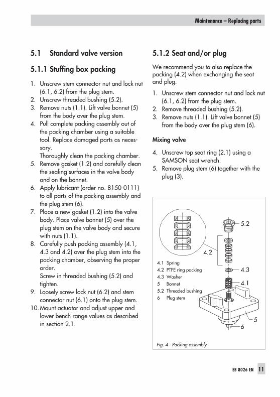
5.1.1 Stuffing box packing
1. Unscrew stem connector nut and lock nut(6.1, 6.2) from the plug stem.
2. Unscrew threaded bushing (5.2).3. Remove nuts (1.1). Lift valve bonnet (5)
from the body over the plug stem.4. Pull complete packing assembly out of
the packing chamber using a suitabletool. Replace damaged parts as neces-sary.Thoroughly clean the packing chamber.
5. Remove gasket (1.2) and carefully cleanthe sealing surfaces in the valve bodyand on the bonnet.
6. Apply lubricant (order no. 8150-0111)to all parts of the packing assembly andthe plug stem (6).
7. Place a new gasket (1.2) into the valvebody. Place valve bonnet (5) over theplug stem on the valve body and securewith nuts (1.1).
8. Carefully push packing assembly (4.1,4.3 and 4.2) over the plug stem into thepacking chamber, observing the properorder.Screw in threaded bushing (5.2) andtighten.
9. Loosely screw lock nut (6.2) and stemconnector nut (6.1) onto the plug stem.
10.Mount actuator and adjust upper andlower bench range values as describedin section 2.1.
5.1.2 Seat and/or plug
We recommend you to also replace thepacking (4.2) when exchanging the seatand plug.
1. Unscrew stem connector nut and lock nut(6.1, 6.2) from the plug stem.
2. Remove threaded bushing (5.2).3. Remove nuts (1.1). Lift valve bonnet (5)
from the body over the plug stem (6).
Mixing valve
4. Unscrew top seat ring (2.1) using aSAMSON seat wrench.
5. Remove plug stem (6) together with theplug (3).
EB 8026 EN 11
Maintenance – Replacing parts
Fig. 4 · Packing assembly
4.1 Spring4.2 PTFE ring packing4.3 Washer5 Bonnet5.2 Threaded bushing6 Plug stem
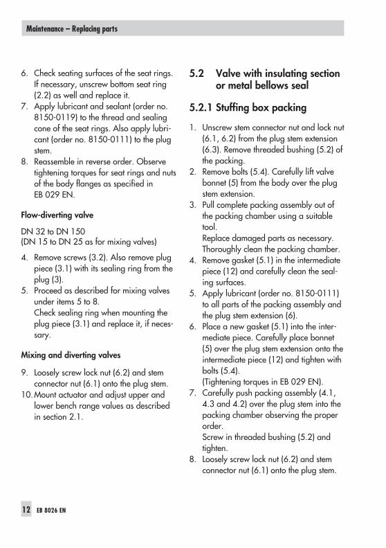
6. Check seating surfaces of the seat rings.If necessary, unscrew bottom seat ring(2.2) as well and replace it.
7. Apply lubricant and sealant (order no.8150-0119) to the thread and sealingcone of the seat rings. Also apply lubri-cant (order no. 8150-0111) to the plugstem.
8. Reassemble in reverse order. Observetightening torques for seat rings and nutsof the body flanges as specified inEB 029 EN.
Flow-diverting valve
DN 32 to DN 150(DN 15 to DN 25 as for mixing valves)
4. Remove screws (3.2). Also remove plugpiece (3.1) with its sealing ring from theplug (3).
5. Proceed as described for mixing valvesunder items 5 to 8.Check sealing ring when mounting theplug piece (3.1) and replace it, if neces-sary.
Mixing and diverting valves
9. Loosely screw lock nut (6.2) and stemconnector nut (6.1) onto the plug stem.
10.Mount actuator and adjust upper andlower bench range values as describedin section 2.1.
5.2 Valve with insulating sectionor metal bellows seal
5.2.1 Stuffing box packing
1. Unscrew stem connector nut and lock nut(6.1, 6.2) from the plug stem extension(6.3). Remove threaded bushing (5.2) ofthe packing.
2. Remove bolts (5.4). Carefully lift valvebonnet (5) from the body over the plugstem extension.
3. Pull complete packing assembly out ofthe packing chamber using a suitabletool.Replace damaged parts as necessary.Thoroughly clean the packing chamber.
4. Remove gasket (5.1) in the intermediatepiece (12) and carefully clean the seal-ing surfaces.
5. Apply lubricant (order no. 8150-0111)to all parts of the packing assembly andthe plug stem extension (6).
6. Place a new gasket (5.1) into the inter-mediate piece. Carefully place bonnet(5) over the plug stem extension onto theintermediate piece (12) and tighten withbolts (5.4).(Tightening torques in EB 029 EN).
7. Carefully push packing assembly (4.1,4.3 and 4.2) over the plug stem into thepacking chamber observing the properorder.Screw in threaded bushing (5.2) andtighten.
8. Loosely screw lock nut (6.2) and stemconnector nut (6.1) onto the plug stem.
12 EB 8026 EN
Maintenance – Replacing parts

EB 8026 EN 13
Maintenance – Replacing parts
Fig. 5 · Version with bellows seal or insulating section (without welded-on bellows (6.6) for insulating section)
1.1 Nuts3 Plug3.1 Plug piece3.2 Screws4.2 Packing5 Bonnet5.1 Sealing ring5.2 Threaded bushing5.3 Travel indicator scale5.4 Bolts6 Plug stem6.1 Stem connector nut6.2 Lock nut6.3 Plug stem extension6.4 Lock washers
DN 15 to 80, Order no. 8382-231DN 100 to 150, Order no. 8382-2321
6.5 Nut6.6 Metal bellows11 Test connection12 Intermediate piece
Mixing valve (left)and
flow-diverting valve (right)

9. Mount actuator and adjust upper andlower bench range values as describedin section 2.1.
5.2.2 Seat and plug
We recommend also to replace the packing(4.2) when installing a new seat and plug.
Caution!To avoid damage in the metal bel-lows version (the version with insulat-ing section does not have a bellows),make sure that no torque is appliedto the bellows, which is screwed tothe intermediate piece. It is recom-mended to use a SAMSON clamp-ing tool.
1. Unscrew stem connector nut and lock nut(6.1, 6.2) from the plug stem.
2. Remove threaded bushing (5.2).3. Remove bolts (5.4). Carefully lift bonnet
(5) from the intermediate piece (12) overthe plug stem extension (6.3).
Mixing valves
4. Insert SAMSON plug tool through valveport B to hold the plug stationary. Un-screw nut (6.5) using a socket wrench.
5. Tightly screw stem connector nut (6.1)and lock nut (6.2) onto the free threadedend of the plug stem extension (6.3) tohold the plug stem stationary.
6. Unscrew plug from the plug stem exten-sion using a SAMSON plug tool.
7. Remove nuts (1.1) from the body. Lift in-termediate piece (12) together with theplug stem extension (6.3) from the valvebody.If necessary, replace the metal bellowstogether with the plug stem extension(see section 5.2.3).
8. Unscrew top seat ring (2.1) and removeplug from the body. Unscrew bottomseat ring (2.2) as well.
Diverting valves
DN 32 to DN 150(DN 15 to DN 25 as for mixing valves)
4. Remove screw (3.2) from the plugthrough valve port B. Take plug piece(3.1) together with the sealing ring offthe plug (3).
5. Remove nuts (1.1). Also remove interme-diate piece (12) together with plug stemextension, plug stem and plug (3) fromthe valve body (1).
6. Tightly screw stem connector nut (6.1)and lock nut (6.2) onto the free threadedend of the plug stem extension (6.3) tohold the plug stem stationary.
7. Unscrew plug (3) from the plug stem ex-tension (6.3).If necessary, replace the metal bellowstogether with the plug stem extension(see section 5.2.3).
8. Replace seats as described in section5.2.2.
9. Apply lubricant (order no. 8150-0111)to the plug stem (6) of the new plug.Make sure that both lock washers (6.4)are still located in the plug stem exten-
14 EB 8026 EN
Maintenance – Replacing parts

sion. Tightly screw plug stem into plugstem extension (6.3) with a tighteningtorque of 50 Nm for Ø 10 mm and80 Nm for Ø 16 mm.
5.2.3 Metal bellows
Refer to section 5.2.2, item 7 for mixing andflow-diverting valves.
1. Pull plug stem extension with weld-onmetal bellows (6.6) out of the intermedi-ate piece.
2. Clean seating surfaces on the intermedi-ate piece.
3. Push new plug stem extension includingmetal bellows into the intermediate piece(12).
5.2.4 Reassembly
1. Place a new gasket (1.2) into the valvebody. Place intermediate piece ontovalve body and tighten with nuts (1.1).Observe tightening torques as specifiedin EB 029 EN.
2. Place a new gasket (5.1) into intermedi-ate piece, place it on the valve bonnet(5) and fasten with nuts and bolts (5.4).Observe tightening torques as specifiedin EB 029 EN.
3. Tighten threaded bushing (5.2).4. Loosely screw lock nut (6.2) and stem
connector nut (6.1) onto plug stem ex-tension (6.3) or plug stem.
5. Mount actuator and adjust upper andlower bench range values as describedin section 2.1.
EB 8026 EN 15
Maintenance – Replacing parts

6 Material identifying marks
Guide bushing, seat and plug have the fol-lowing identifying marks:
Guide bushing (groove on plane face)
No groove: 1.4305 Sharp recessed groove: 1.4571 Flat recessed groove: Hastelloy
SeatThe material number is either stamped orengraved on the seat.
Stellited seats are marked by astamped-on "st".
PlugGroove below the plug stem thread:
No groove: 1.4006 Sharp recessed groove: 1.4571 Two sharp recessed grooves: 1.4301 Flat recessed groove: Hastelloy When other materials are used, either
the material number or its designation isengraved on the plug.
The Kvs value and characteristic are en-graved on the plug.
Stellited plugs are marked by anengraved "st".
Dimensions and weights of the valveversions can be found in Data SheetT 8026 EN.
16 EB 8026 EN
Material identifying marks
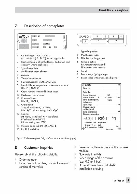
7 Description of nameplates
8 Customer inquiries
Please submit the following details:
Order number Type, product number, nominal size and
version of the valve
Pressure and temperature of the processmedium
Flow rate in m3/h Bench range of the actuator
(e.g. 0.2 to 1 bar) Has a strainer been installed? Installation drawing
EB 8026 EN 17
Description of nameplates
Fig. 6 · Valve nameplate (left) and actuator nameplates (right)
1 CE marking or "Art. 3, Abs.3"(see article 3, § 3 of PED), where applicable
2 Identification no. of notified body, fluid group andcategory, where applicable
3 Type designation4 Modification index of valve5 Material6 Year of manufacture7 Nominal size: DIN: DN, ANSI: Size8 Permissible excess pressure at room temperature
DIN: PN, ANSI: CL9 Order number with modification index10 Position of item in order11 Flow coefficient:
DIN: KVS, ANSI: Cv
12 Characteristic:% equal percentage, Lin linear,DIN: A/Z quick opening, ANSI: O/C
13 Sealing:ME metal, ST stellited, Ni nickel-platedPT soft sealing with PTFE,PK soft sealing with PEEK
14 Pressure-balanced: DIN: D, ANSI: B15 I or III flow divider
1 Type designation2 Modification index3 Effective diaphragm area4 Fail-safe action:
FA Actuator stem extendsFE Actuator stem retracts
5 Travel6 Bench range (spring range)7 Bench range with pretensioned springs

SAMSON AG · MESS- UND REGELTECHNIKWeismüllerstraße 3 · 60314 Frankfurt am Main · GermanyPhone: +49 69 4009-0 · Fax: +49 69 4009-1507Internet: http://www.samson.de EB 8026 EN S/
Z20
05-0
1
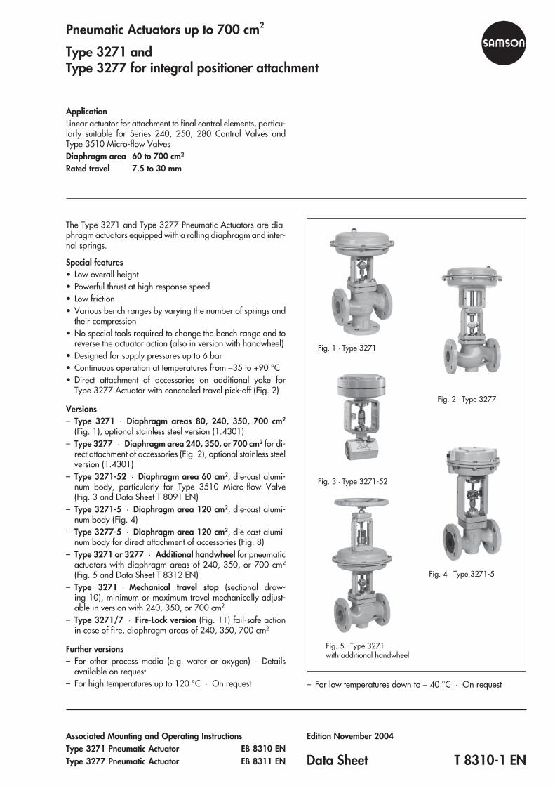
Pneumatic Actuators up to 700 cm2
Type 3271 andType 3277 for integral positioner attachment
ApplicationLinear actuator for attachment to final control elements, particu-larly suitable for Series 240, 250, 280 Control Valves andType 3510 Micro-flow ValvesDiaphragm area 60 to 700 cm2
Rated travel 7.5 to 30 mm
The Type 3271 and Type 3277 Pneumatic Actuators are dia-phragm actuators equipped with a rolling diaphragm and inter-nal springs.
Special features• Low overall height• Powerful thrust at high response speed• Low friction• Various bench ranges by varying the number of springs and
their compression• No special tools required to change the bench range and to
reverse the actuator action (also in version with handwheel)• Designed for supply pressures up to 6 bar• Continuous operation at temperatures from −35 to +90 °C• Direct attachment of accessories on additional yoke for
Type 3277 Actuator with concealed travel pick-off (Fig. 2)
Versions– Type 3271 ⋅ Diaphragm areas 80, 240, 350, 700 cm2
(Fig. 1), optional stainless steel version (1.4301)– Type 3277 Diaphragm area 240, 350, or 700 cm2 for di-
rect attachment of accessories (Fig. 2), optional stainless steelversion (1.4301)
– Type 3271-52 Diaphragm area 60 cm2, die-cast alumi-num body, particularly for Type 3510 Micro-flow Valve(Fig. 3 and Data Sheet T 8091 EN)
– Type 3271-5 Diaphragm area 120 cm2, die-cast alumi-num body (Fig. 4)
– Type 3277-5 ⋅ Diaphragm area 120 cm2, die-cast alumi-num body for direct attachment of accessories (Fig. 8)
– Type 3271 or 3277 ⋅ Additional handwheel for pneumaticactuators with diaphragm areas of 240, 350, or 700 cm2
(Fig. 5 and Data Sheet T 8312 EN)– Type 3271 Mechanical travel stop (sectional draw-
ing 10), minimum or maximum travel mechanically adjust-able in version with 240, 350, or 700 cm2
– Type 3271/7 Fire-Lock version (Fig. 11) fail-safe actionin case of fire, diaphragm areas of 240, 350, 700 cm2
Further versions– For other process media (e.g. water or oxygen) ⋅ Details
available on request– For high temperatures up to 120 °C ⋅ On request – For low temperatures down to − 40 °C ⋅ On request
Associated Mounting and Operating InstructionsType 3271 Pneumatic Actuator EB 8310 ENType 3277 Pneumatic Actuator EB 8311 EN
Edition November 2004
Data Sheet T 8310-1 EN
Fig. 1 ⋅ Type 3271
Fig. 4 ⋅ Type 3271-5
Fig. 2 ⋅ Type 3277
Fig. 3 ⋅ Type 3271-52
Fig. 5 ⋅ Type 3271with additional handwheel
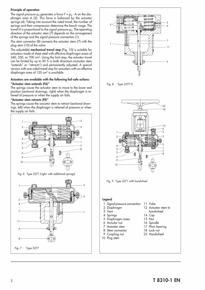
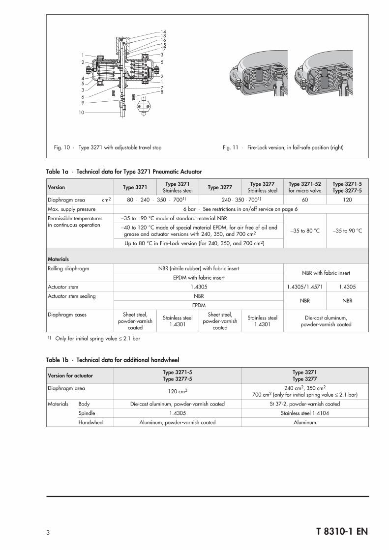
Principle of operationThe signal pressure pst generates a force F = pst ⋅ A on the dia-phragm area A (2). This force is balanced by the actuatorsprings (4). Taking into account the rated travel, the number ofsprings and their compression determine the bench range. Thetravel H is proportional to the signal pressure pst. The operatingdirection of the actuator stem (7) depends on the arrangementof the springs and the signal pressure connection (1).The stem connector (8) connects the actuator stem (7) with theplug stem (10) of the valve.The adjustable mechanical travel stop (Fig. 10) is suitable foractuators made of sheet steel with effective diaphragm areas of240, 350, or 700 cm2. Using the limit stop, the actuator travelcan be limited by up to 50 % in both directions (actuator stem“extends” or “retracts”) and permanently adjusted. A specialversion with one-sided travel stop for actuators with an effectivediaphragm area of 120 cm2 is available.
Actuators are available with the following fail-safe actions:“Actuator stem extends (FA)“The springs cause the actuator stem to move to the lower endposition (sectional drawings, right) when the diaphragm is re-lieved of pressure or when the supply air fails.“Actuator stem retracts (FE)“The springs cause the actuator stem to retract (sectional draw-ings, left) when the diaphragm is relieved of pressure or whenthe supply air fails.
2 T 8310-1 EN
25
1
4
7
11
6
Fig. 8 ⋅ Type 3277-5
1 3
5
1
2
4
7
11
6
8
Fig. 7 ⋅ Type 3277
2318
1263
5
2178
1
2
453
69
10
Fig. 9 ⋅ Type 3271 with handwheel
1
2
4
5
3
6
3
5
1
2
78
9
10
Fig. 6 ⋅ Type 3271 (right: with additional springs)
Legend1 Signal pressure connection2 Diaphragm3 Vent4 Springs5 Diaphragm cases6 Annular nut7 Actuator stem8 Stem connector9 Coupling nut
10 Plug stem
11 Yoke12 Actuator stem to
handwheel14 Cap15 Nut16 Spindle17 Plain bearing18 Lock nut23 Handwheel
3 T 8310-1 EN
Table 1a Technical data for Type 3271 Pneumatic Actuator
Version Type 3271 Type 3271Stainless steel Type 3277 Type 3277
Stainless steelType 3271-52for micro valve
Type 3271-5Type 3277-5
Diaphragm area cm2 80 ⋅ 240 ⋅ 350 ⋅ 7001) 240 ⋅ 350 ⋅ 7001) 60 120
Max. supply pressure 6 bar ⋅ See restrictions in on/off service on page 6
Permissible temperaturesin continuous operation
−35 to 90 °C made of standard material NBR
−35 to 80 °C −35 to 90 °C−40 to 120 °C made of special material EPDM, for air free of oil andgrease and actuator versions with 240, 350, and 700 cm2
Up to 80 °C in Fire-Lock version (for 240, 350, and 700 cm2)
Materials
Rolling diaphragm NBR (nitrile rubber) with fabric insertNBR with fabric insert
EPDM with fabric insert
Actuator stem 1.4305 1.4305/1.4571 1.4305
Actuator stem sealing NBRNBR NBR
EPDM
Diaphragm cases Sheet steel,powder-varnish
coated
Stainless steel1.4301
Sheet steel,powder-varnish
coated
Stainless steel1.4301
Die-cast aluminum,powder-varnish coated
1) Only for initial spring value ≤ 2.1 bar
Table 1b Technical data for additional handwheel
Version for actuatorType 3271-5Type 3277-5
Type 3271Type 3277
Diaphragm area 120 cm2 240 cm2, 350 cm2
700 cm2 (only for initial spring value ≤ 2.1 bar)
Materials Body Die-cast aluminum, powder-varnish coated St 37-2, powder-varnish coated
Spindle 1.4305 Stainless steel 1.4104
Handwheel Aluminum, powder-varnish coated Aluminum
14
12
45369
10
1816
173
5
2178
15
Fig. 10 ⋅ Type 3271 with adjustable travel stop Fig. 11 ⋅ Fire-Lock version, in fail-safe position (right)

4 T 8310-1 EN
Table 2 Bench ranges for pneumatic actuators up to 700 cm2
Effe
ctiv
edi
aphr
agm
area
[cm
2 ]
Rate
dtra
vel[
mm
]
Trav
elvo
lum
eat
rate
dtra
vel[
dm3 ]
Dea
dvo
lum
e[d
m3 ]
Max
.tra
vel[
mm
]1)2
)
Benc
hra
nge
[bar
](s
igna
lpre
ssur
era
nge
atra
ted
trave
l)
Add
ition
ally
poss
ible
sprin
gco
mpr
essi
on[%
]
Ope
ratin
gra
nge
with
sprin
gco
mpr
essi
on[b
ar]
Num
ber
ofsp
rings
Sprin
gfo
rce
at0
mm
trave
l[kN
]1)
Sprin
gfo
rce
atra
ted
trave
l[kN
]
Thrust [kN] at rated traveland a supply pressure [bar] of
1.4 2.0 3.0 4.0 5.0 6.0
60 7.5 0.09 0.1 10.5
0.2...1.0
0
− 2 0.12 0.6 0.24 0.6 1.2 1.8 2.4 3
0.4...2.0 − 4 0.24 1.2 − 0.6 1.2 1.8 2.4
1.4...2.33) − 4 0.84 1.38 − 1.02 1.62 2.22
2.1...3.33) − 8 1.26 1.98 − 0.42 1.02 1.62
80 15 0.12 0.13 16
0.2...1.0
12.5
0.3...1.1 3 0.16 0.8 0.32 0.8 1.6 2.4 3.2 4
0.4...2.0 0.6...2.2 6 0.32 1.6 − 0.8 1.6 2.4 3.2
0.6...3.0 0.9...3.3 12 0.48 2.4 − 0.8 1.6 2.4
120 7.5 0.09 0.12 9
0.4...0.8
0
− 3 0.48 0.96 0.72 1.44 2.64 3.84 5.04 6.24
0.8...1.6 − 6 0.96 1.92 − 0.48 1.68 2.88 4.08 5.28
Version forType 3510 Micro-flow Valve
1.7...2.13) 1.7...2.1 6 2.04 2.52 − 1.08 2.28 3.48 4.68
2.4...3.03) 2.4...3.0 12 2.88 3.6 − 1.2 2.4 3.6
120 15 0.2 0.10
16(17)
0.2...1.012.5
0.3...1.1 3 0.24 1.2 − 1.2 2.4 3.6 4.8 6
0.4...2.0 0.6...2.2 6 0.48 2.4 − 1.2 2.4 3.6 4.8
15(17)
1.4...2.33)
01.4...2.3 6 1.68 2.76 − 0.84 2.04 3.24 4.44
2.1...3.33) 2.1...3.3 12 2.52 3.96 − 0.84 2.04 3.24
240 15 0.36 0.38 17
0.2...1.0
12.5
0.3...1.1 3 0.48 2.4 0.96 2.4 4.8 7.2 9.6 12
0.4...2.0 0.6...2.2 6 0.96 4.8 − 2.4 4.8 7.2 9.6
0.6...3.0 0.9...3.3 12 1.44 7.2 − 2.4 4.8 7.2
350 15 0.53 0.6
22
0.2...1.0
25
0.4...1.2 3 0.7 3.5 1.4 3.5 7 10.5 14 17.5
0.4...2.0 0.8...2.4 6 1.4 7 − 3.5 7 10.5 14
0.6...3.0 1.2...3.6 12 2.1 10.5 − 3.5 7 10.5
151.4...2.33)
01.4...2.3 6 4.9 8.05 − 2.45 5.95 9.45 13
2.1...3.33) 2.1...3.3 12 7.35 11.6 − 2.45 5.95 9.45
700 30 2.1 2.4
38
0.2...1.0
25
0.4...1.2 3 1.4 7 2.8 7 14 21 28 35
0.4...2.0 0.8...2.4 6 2.8 14 − 7 14 21 28
0.6...3.0 1.2...3.6 12 4.2 21 − 7 14 21
30
1.4...2.33)
0
1.4...2.3 8 9.8 16.1 − 4.9 11.9 18.9 25.9
2.1...3.33) 2.1...3.3 12 14.7 23.1 − 4.9 11.9 18.9
2.35...3.83) 4) 2.35...3.8 15 16.5 26.6 − 1.4 8.4 15.4
2.6 ...4.33) 4) 2.6...4.3 18 18.2 30.1 − 4.9 11.9
1) Based on lower bench range value, taking zero travel (to unseat the plug) into account2) Zero travel as in Table 3 depending on fail-safe action3) Pretensioned springs4) Version not available with additional handwheel

5 T 8310-1 EN
H
H7
a2H5
H4H6
a1ØD
ØD1
H2H1
H
H4H6
ØD2Ød
ØD
a
a
ØD ØDa
a
Ød
H6H4
H
ØD2
a
a
H
H6H4
ØD
ØD2Ød
H7
a
a
H
H8
H6H4
ØD
ØD2Ød
ØD1
ØD
ØD2
55
Ød
H
H1
H4 H6
H5a2
H2
ØD2Ød
Ød
M14x1
H
H5
H4H6
14
Max
. 58
at 7
.5 m
m tr
avel
10.5
ØD2Ød
a1
Fig. 12 ⋅ Type 3271-5
Fig. 12a ⋅ Types 3271-5/3277-5 with7.5 mm travel for Type 3510 Micro Valve Fig. 13 ⋅ Type 3277-5
Fig. 14 ⋅ Type 3271 (700 cm2 version with lifting ring)
Fig. 15 ⋅ Type 3277 (700 cm2 version with lifting ring)
Fig. 16 ⋅ Type 3271 with adjustable travel stop
Fig. 17 ⋅ Type 3271 with additional handwheel
Fig. 18 ⋅ Type 3277 with additional handwheel
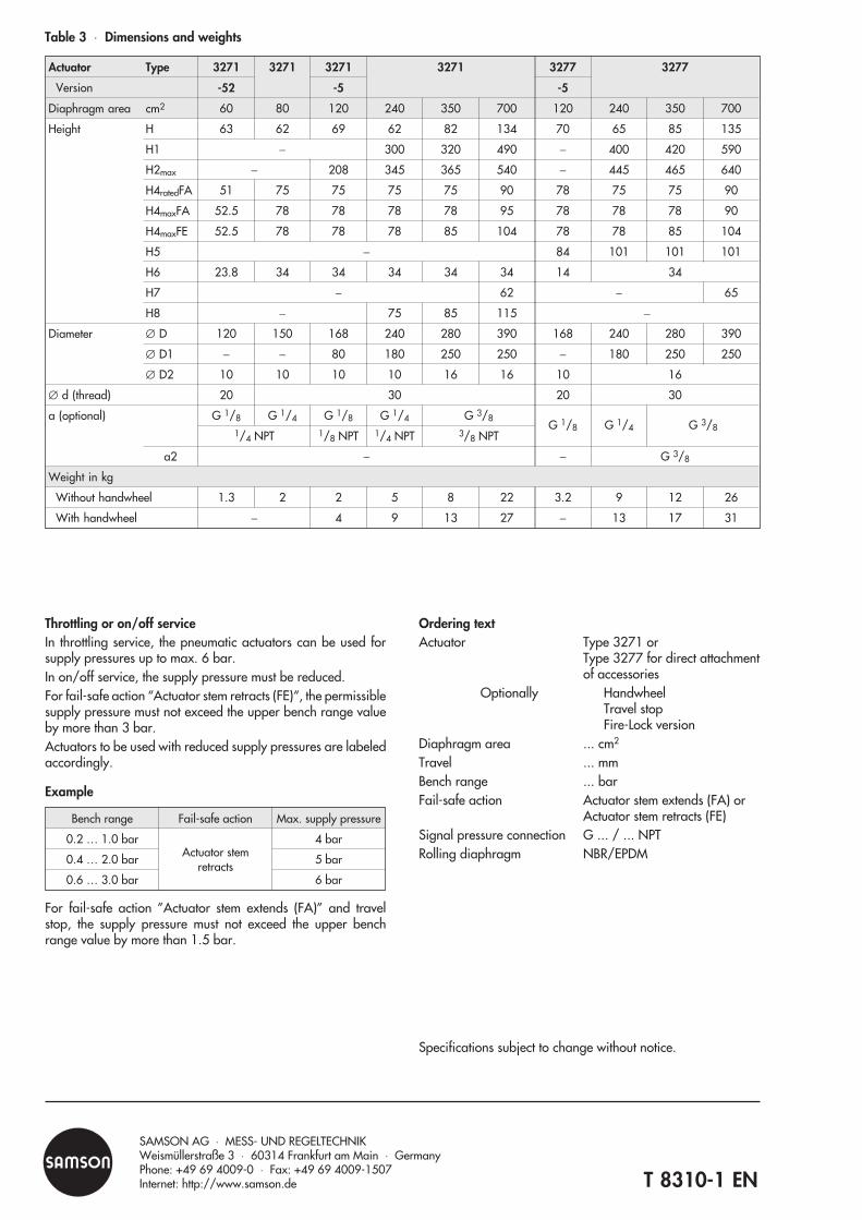
Throttling or on/off serviceIn throttling service, the pneumatic actuators can be used forsupply pressures up to max. 6 bar.In on/off service, the supply pressure must be reduced.For fail-safe action “Actuator stem retracts (FE)“, the permissiblesupply pressure must not exceed the upper bench range valueby more than 3 bar.Actuators to be used with reduced supply pressures are labeledaccordingly.
Example
Bench range Fail-safe action Max. supply pressure
0.2 … 1.0 barActuator stem
retracts
4 bar
0.4 … 2.0 bar 5 bar
0.6 … 3.0 bar 6 bar
For fail-safe action ”Actuator stem extends (FA)” and travelstop, the supply pressure must not exceed the upper benchrange value by more than 1.5 bar.
Ordering textActuator Type 3271 or
Type 3277 for direct attachmentof accessories
Optionally HandwheelTravel stopFire-Lock version
Diaphragm area ... cm2
Travel ... mmBench range ... barFail-safe action Actuator stem extends (FA) or
Actuator stem retracts (FE)Signal pressure connection G ... / ... NPTRolling diaphragm NBR/EPDM
Specifications subject to change without notice.
T 8310-1 EN
SAMSON AG ⋅ MESS- UND REGELTECHNIKWeismüllerstraße 3 ⋅ 60314 Frankfurt am Main ⋅ GermanyPhone: +49 69 4009-0 ⋅ Fax: +49 69 4009-1507Internet: http://www.samson.de
Table 3 Dimensions and weights
Actuator Type 3271 3271 3271 3271 3277 3277
Version -52 -5 -5
Diaphragm area cm2 60 80 120 240 350 700 120 240 350 700
Height H 63 62 69 62 82 134 70 65 85 135
H1 − 300 320 490 − 400 420 590
H2max − 208 345 365 540 − 445 465 640
H4ratedFA 51 75 75 75 75 90 78 75 75 90
H4maxFA 52.5 78 78 78 78 95 78 78 78 90
H4maxFE 52.5 78 78 78 85 104 78 78 85 104
H5 − 84 101 101 101
H6 23.8 34 34 34 34 34 14 34
H7 − 62 − 65
H8 − 75 85 115 −
Diameter ∅ D 120 150 168 240 280 390 168 240 280 390
∅ D1 − − 80 180 250 250 − 180 250 250
∅ D2 10 10 10 10 16 16 10 16
∅ d (thread) 20 30 20 30
a (optional) G 1/8 G 1/4 G 1/8 G 1/4 G 3/8G 1/8 G 1/4 G 3/8
1/4 NPT 1/8 NPT 1/4 NPT 3/8 NPT
a2 − − G 3/8
Weight in kg
Without handwheel 1.3 2 2 5 8 22 3.2 9 12 26
With handwheel − 4 9 13 27 − 13 17 31

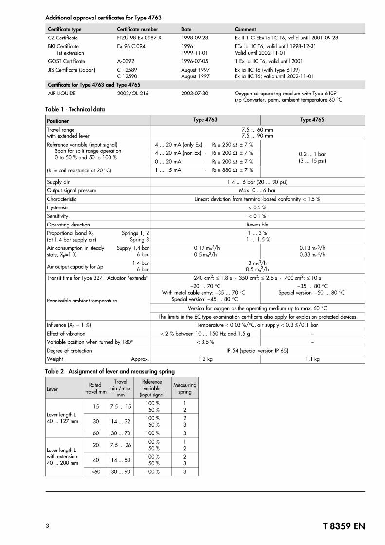
ApplicationSingle-acting positioner for attachment to pneumatic controlvalves. Reference variable is either a standardized electricsignal from 4(0) to 20 mA or 1 to 5 mA (Type 4763) or apneumatic standardized signal from 0.2 to 1 bar (3 to 15 psi)(Type 4765). Rated travels from 7.5 to 90 mm
The positioners ensure predetermined assignment of the valvestem position (controlled variable x) to the electric or pneumaticinput signals (reference variable w) supplied by the controller.They compare the input signal coming from the controller to thetravel of the control valve and produce the correspondingpneumatic output signal pressure pst (output variable y). Special features• Compact, low-maintenance design• Any mounting position possible• Resistant to mechanical vibrations• Reversible operating direction• Excellent dynamic behavior• Suitable for normal or split-range operation• Adjustable proportional band (P-band)• Adjustable air output capacity• Low energy consumption• Special versions for oxygenAttachment to valves with cast yokes or rod-type yokes accordingto IEC 60534-6.Optionally available with two pressure gauges to monitor sup-ply air and signal pressure, with stainless steel housing andconnections optionally nickel-plated or made of stainless steel.The Type 4765 Pneumatic Positioner can be subsequentlymodified to an electropneumatic positioner.VersionsAll versions of Type 4763 Electropneumatic PositionerReference variable: 4(0) to 20 mA, 1 to 5 mA,Supply air: 1.4 to 6 bar (20 to 90 psi),Signal range: 0 to 6 bar (0 to 90 psi)Type 4763-0 ⋅ Version for non-hazardous areasType 4763-1 ⋅ Version for hazardous areasinput circuit with type of protection II 2 G EEx ia IIC T6 acc. toATEX (see explosion protection certificates" on pages 2 and 3)Type 4763-8 ⋅ i/p Positioner in EEx nA "non-sparking"Type 4765/6116 ⋅ i/p Positioner with type of protection"Flameproof Enclosure" EEx d with Type 6116 i/p Converter (Figs. 2 and 3; for certificates, refer to Data Sheet T 6116 EN).Type 4765 ⋅ Pneumatic Positioner Reference variable: 0.2 to 1 bar (3 to 15 psi) Signal range: 0 to 6 bar (0 to approximately 90 psi)Supply air: 1.4 to 6 bar (20 to 90 psi)
Fig. 1 ⋅ Type 4763 / Type 4765 Positioner
Edition September 2004
Data Sheet T 8359 EN
Associated Information Sheet T 8350 EN
Electropneumatic Positioner Type 4763
Pneumatic Positioner Type 4765
JIS
Fig. 2 ⋅ Type 6116 i/p Converter, opened
Fig. 3 ⋅ Type 4765/6116 Ex d PositionerAttachment to NAMUR rib

Principle of operation The only difference between the Type 4765 Pneumatic Position-er and the Type 4763 Electropneumatic Positioner is that anelectropneumatic (i/p) converter has been added to the latter inorder to convert the electric signal received from a controllerinto a proportional pneumatic signal.These positioners use a flapper-nozzle system which operatesaccording to the force-balance principle. They can be appliedfor both normal and split-range operation.
Operating directionWhen the reference variable (pe) increases, the pneumaticoutput signal pressure pst can be selected to be increasing-increasing (direct action >>) or increasing-decreasing (reverseaction <>). The operating direction depends on the position ofthe nozzle block that can be turned by 180°. The visible mark(>> or <>) indicates the respective operating direction. If theoperating direction or the fail-safe position is to be subsequentlymodified, note that the positioner must also be mounted at adifferent position (Figs. 5 to 8)!
Attachment according to IEC 60534-6 and NAMUR The various ways in which the positioner can be attached to theactuator correspond to the IEC 60534-6 and NAMUR recom-mendation. Positioners may be attached to valves with eithercast yokes (e.g. SAMSON Series 240) or rod-type yokes.Each type of attachment requires special mounting parts.
Combining the positioner and the actuatorFigs. 5 to 8 schematically illustrate the arrangement of theactuator, the mounting position of the positioner, the referencevariable, and the operating direction.Fail-safe actionThe pneumatic actuators (Type 3271 and Type 3277) areavailable with the following fail-safe actions. They move thevalve in the predetermined position whenever the signal press-ure decreases or air supply fails:Actuator stem "extends" (Figs. 5, 6)Whenever the pressure acting on the diaphragm decreases orair supply fails, the compression springs installed in the actuatorforce the actuator stem to extend.Actuator stem "retracts" (Figs. 7, 8)Same as above, except: the compression springs force theactuator stem to retract.Refer to Data Sheets T 8310 EN and T 8311 EN for more details.Figs. 5 to 8 illustrate the different operating directions and themounting positions of the positioner. "Right..." and "Left attach-ment" apply when looking onto the lever (1) and plate (2).
T 8359 EN2
Fig. 7 ⋅ Operating direction >> Right attachment
Fig. 8 ⋅ Operating direction<> Left attachment
1
Fig. 5 ⋅ Operating direction >> Left attachment
Fig. 6 ⋅ Operating direction <> Right attachment
Actuator stem "extends"
Actuator stem "retracts"
i/p converter Lever
Fig. 4 ⋅ Type 4763 Electropneumatic Positioner
Summary of approved explosion protection certificates for Type 4763 Electropneumatic Positioner
Certificate type Certificate number Date Comment
Statement of Conformity PTB 03 ATEX 2183 X 2003-09-30 II 3 G EEx nA II T6, Zone 2
EC Type Examination Cert. PTB 02 ATEX 2078 2002-07-19 II 2 G EEx ia IIC T6
Certificate of Conformity1st Addendum2nd Addendum
PTB No. Ex-93.C.4031 1993-05-051993-11-221994-05-30
EEx ia IIC T6−45 °C ambient temperatureWith i/p module 6109
SEV Certificate 98.5.50771.03 1998-04-24 EEx ia IIC T4-T6
FMRC Certificate J.I. 1Y8A9.AXJ.I. 5Y2A3.AX
1994-05-111995-04-26
Class I, II, III; Div. IGroups A, B, C, D, E, F, G; Div. 2
CSA LR 54227-20 1996-04-22 Class I; Div. I; Groups A, B, C, D; Encl. 3
EEx d certifications for Type 6116 i/p Converter can be found in Data Sheet T 6116 EN.
T 8359 EN3
Table 1 ⋅ Technical data
Positioner Type 4763 Type 4765
Travel rangewith extended lever
7.5 ... 60 mm7.5 ... 90 mm
Reference variable (input signal) Span for split-range operation0 to 50 % and 50 to 100 %
(Ri = coil resistance at 20 °C)
4 ... 20 mA (only Ex) ⋅ Ri ≅ 250 Ω ± 7 %
0.2 ... 1 bar(3 ... 15 psi)
4 ... 20 mA (non-Ex) ⋅ Ri ≅ 200 Ω ± 7 %
0 ... 20 mA ⋅ Ri ≅ 200 Ω ± 7 %
1 ... 5 mA ⋅ Ri ≅ 880 Ω ± 7 %
Supply air 1.4 ... 6 bar (20 ... 90 psi)
Output signal pressure Max. 0 ... 6 bar
Characteristic Linear; deviation from terminal-based conformity < 1.5 %
Hysteresis < 0.5 %
Sensitivity < 0.1 %
Operating direction Reversible
Proportional band Xp (at 1.4 bar supply air)
Springs 1, 2Spring 3
1 ... 3 % 1 ... 1.5 %
Air consumption in steady state, Xp=1 %
Supply 1.4 bar 6 bar
0.19 mn3/h0.5 mn3/h
0.13 mn3/h0.33 mn3/h
Air output capacity for ∆p1.4 bar
6 bar3 mn
3/h8.5 mn
3/h
Transit time for Type 3271 Actuator "extends" 240 cm2: ≤ 1.8 s ⋅ 350 cm2: ≤ 2.5 s ⋅ 700 cm2: ≤ 10 s
Permissible ambient temperature
−20 ... 70 °CWith metal cable entry: −35 ... 70 °C
Special version: −45 ... 80 °C
−35 ... 80 °CSpecial version: −50 ... 80 °C
Version for oxygen as the operating medium up to max. 60 °C
The limits in the EC type examination certificate also apply for explosion-protected devices
Influence (Xp = 1 %) Temperature < 0.03 %/°C, air supply < 0.3 %/0.1 bar
Effect of vibration < 2 % between 10 ... 150 Hz and 1.5 g −
Variable position when turned by 180° < 3.5 % −
Degree of protection IP 54 (special version IP 65)
Weight Approx. 1.2 kg 1.1 kg
Table 2 ⋅ Assignment of lever and measuring spring
LeverRated
travel mm
Travelmin./max.
mm
Reference variable
(input signal)
Measuringspring
Lever length L40 ... 127 mm
15 7.5 ... 15 100 % 50 %
12
30 14 ... 32 100 % 50 %
23
60 30 ... 70 100 % 3
Lever length Lwith extension40 ... 200 mm
20 7.5 ... 26 100 % 50 %
12
40 14 ... 50 100 % 50 %
23
>60 30 ... 90 100 % 3
Additional approval certificates for Type 4763
Certificate type Certificate number Date Comment
CZ Certificate FTZÜ 98 Ex 0987 X 1998-09-28 Ex II 1 G EEx ia IIC T6; valid until 2001-09-28
BKI Certificate1st extension
Ex 96.C.094 19961999-11-01
EEx ia IIC T6; valid until 1998-12-31Valid until 2002-11-01
GOST Certificate A-0392 1996-07-05 1 Ex ia IIC T6, valid until 2001
JIS Certificate (Japan) C 12589C 12590
August 1997August 1997
Ex ia IIC T6 (with Type 6109)Ex ia IIC T6; valid until 2002-11-01
Certificate for Type 4763 and Type 4765
AIR LIQUIDE 2003/OL 216 2003-07-30 Oxygen as operating medium with Type 6109i/p Converter, perm. ambient temperature 60 °C

!"""# """!
$%
% & !'()*+
, """
, """-"""
. $ / '01234*'5, 67)3 8 '0 12349 '5,67)2' 8"
$
: ;
: !"
::$<⋅'::=(-'<'>,'?/@ A B2⋅)+2*6C⋅<D64)46++4+⋅C;D64)46++4*3+7/%%" "
!
"#$ % & % % %';
+//9<'';//,) *
';C-: 2//2<'';//,) 1
* *9 92 2
<*⁄6 **⁄6, 2
' 9+;*"3! *9+;*"3! 9??7( 3
- !6"""9+ * *+"""9+ 9 9
"#$ % & % % &
* *9 92 2
<*⁄6 **⁄6, 2
*⁄9,
'; /)3
' 5!"(/8
( (
'; : *"637**"62+*
:
79
69
Pg 13.5
15 44
2.5
29 114.5157
131.5
27.7
99
L2815
37
49.5
30.5
/
$52)8
:548
>E6+"""*97
9+;*"3
+11 –12
/ 65+89+