mounting bracket – weldable dust caps - cejn.com · coupling size iso – dn dash l w h1 h2 h3 l...
TRANSCRIPT
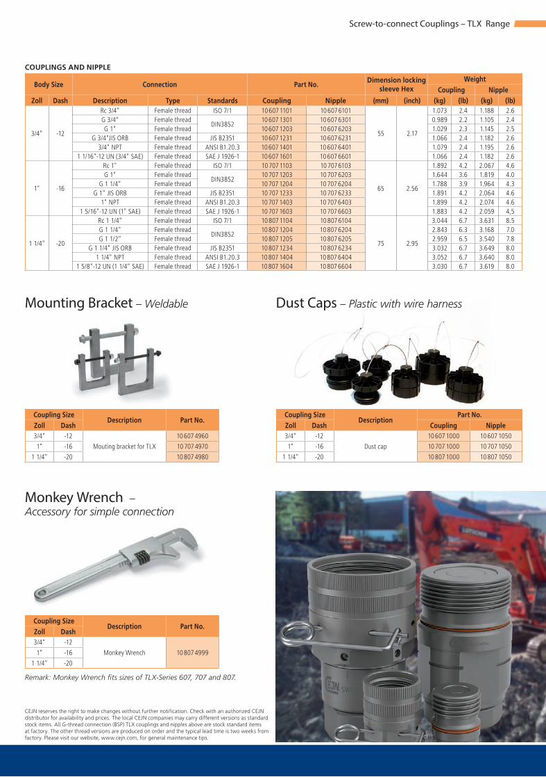
3/4" -12
Rc 3/4" ISO 7/1 10 607 1101 10 607 6101
55 2.17
1.073 2.4 1.188 2.6G 3/4"
DIN385210 607 1301 10 607 6301 0.989 2.2 1.105 2.4
G 1" 10 607 1203 10 607 6203 1.029 2.3 1.145 2.5G 3/4"JIS ORB JIS B2351 10 607 1231 10 607 6231 1.066 2.4 1.182 2.6
3/4" NPT ANSI B1.20.3 10 607 1401 10 607 6401 1.079 2.4 1.195 2.61 1/16"-12 UN (3/4" SAE) SAE J 1926-1 10 607 1601 10 607 6601 1.066 2.4 1.182 2.6
1" -16
Rc 1" ISO 7/1 10 707 1103 10 707 6103
65 2.56
1.892 4.2 2.067 4.6G 1"
DIN385210 707 1203 10 707 6203 1.644 3.6 1.819 4.0
G 1 1/4" 10 707 1204 10 707 6204 1.788 3.9 1.964 4.3G 1" JIS ORB JIS B2351 10 707 1233 10 707 6233 1.891 4.2 2.064 4.6
1" NPT ANSI B1.20.3 10 707 1403 10 707 6403 1.899 4.2 2.074 4.61 5/16"-12 UN (1" SAE) SAE J 1926-1 10 707 1603 10 707 6603 1.883 4.2 2.059 4,5
1 1/4" -20
Rc 1 1/4" ISO 7/1 10 807 1104 10 807 6104
75 2.95
3.044 6.7 3.631 8.5G 1 1/4"
DIN385210 807 1204 10 807 6204 2.843 6.3 3.168 7.0
G 1 1/2" 10 807 1205 10 807 6205 2.959 6.5 3.540 7.8G 1 1/4" JIS ORB JIS B2351 10 807 1234 10 807 6234 3.032 6.7 3.649 8.0
1 1/4" NPT ANSI B1.20.3 10 807 1404 10 807 6404 3.052 6.7 3.640 8.01 5/8"-12 UN (1 1/4" SAE) SAE J 1926-1 10 807 1604 10 807 6604 3.030 6.7 3.619 8.0
3/4" -12 10 607 4960
1" -16 10 707 4970
1 1/4" -20 10 807 4980
3/4" -12
10 807 49991" -16
1 1/4" -20
3/4" -12 10 607 1000 10 607 1050
1" -16 10 707 1000 10 707 1050
1 1/4" -20 10 807 1000 10 807 1050
Body Size Connection Part No.Dimension locking
sleeve HexWeight
Coupling NippleZoll Dash Description Type Standards Coupling Nipple (mm) (inch) (kg) (lb) (kg) (lb)
Female threadFemale threadFemale threadFemale threadFemale threadFemale threadFemale threadFemale threadFemale threadFemale threadFemale threadFemale threadFemale threadFemale threadFemale threadFemale threadFemale threadFemale thread
Coupling SizeDescription Part No.
Zoll Dash
Mouting bracket for TLX
Coupling SizeDescription
Part No.Zoll Dash Coupling Nipple
Dust cap
Coupling SizeDescription Part No.
Zoll Dash
Monkey Wrench
Screw-to-connect Couplings – TLX Range
COUPLINGS AND NIPPLE
Mounting Bracket – Weldable
Monkey Wrench –Accessory for simple connection
Remark: Monkey Wrench fi ts sizes of TLX-Series 607, 707 and 807.
Dust Caps – Plastic with wire harness
CEJN reserves the right to make changes without further notifi cation. Check with an authorized CEJNdistributor for availability and prices. The local CEJN companies may carry different versions as standardstock items. All G-thread connection (BSP) TLX couplings and nipples above are stock standard itemsat factory. The other thread versions are produced on order and the typical lead time is two weeks fromfactory. Please visit our website, www.cejn.com, for general maintenance tips.

www.cejn.com
The Quick ConnectSolution Provider
09 0
014
917
/ 011
4 Co
pyrig
ht ©
201
7 CE
JN C
PG
United Kingdomwww.cejnuk.com
Francewww.cejn.fr
Spainwww.cejn.es
Italywww.cejn.it
Indiawww.cejn.in
Singapurwww.cejn.com.sg
Australiawww.cejn.com.au
Chinawww.cejn.com.ch
Japanwww.cejn.co.jp
South Koreawww.cejn.krSwitzerland
www.cejn.ch
Germanywww.cejn.de
Swedenwww.cejn.com
Denmarkwww.cejn.dk
Swedenwww.cejn.se
U.S.A.www.cejn.us
Méxicowww.cejn.us/es
Brazilwww.cejnbrasil.com.br

www.cejn.com
09 0
014
917
/ 011
4 Co
pyrig
ht ©
201
7 CE
JN C
PG
HYD
RAU
LICS
Hydraulic ProductsFor Clean and leak-free Hydraulic Systems

607 – 3/4”
507 – 1/2”
807 – 1 1/4”
907 – 1 1/2”
707 – 1”
11,0
5,415,1
1
10
100
1000
5
20
60
80
400
40
500
2.6
200
300
52.8
26.4
15.9
10.6
21.1
5.3
264.2
132.1
105.7
79.3
6116.2 87
72.5
5843.529101,5
7 8654320.50.26
1.3
158.5
7.9
23.8
13.2
211.3237.8
90
70
50
30
600700
800900
18.5
907 (Eliminator)
1400 370
1/2" - 8 93 24.6 420 6091 420 6091 1680 24366 1050 152293/4" -12 160 35,2 420 6091 400 5801 1680 24366 1000 145031" -16 285 62,7 420 6091 400 5801 1680 24366 1000 14503
1 1/4" -20 400 88,0 420 6091 400 5801 1680 24366 1000 145031 1/2“ -24 560 147,9 380 5511 380 5511 1520 22045 1000 14503
Screw-to-connect Couplings – TLX Range
QR Code for TLX Series
TLX-Range1/2" (507), 3/4" (607), 1" (707), 1 1/4" (807), 1 1/2" (907)
• The Super-Duty connector with … extremely high resilience to surge � ows
• Flat face screw-to-connect coupling… that handles the pressure impulses… with pure and simple robustness… designated for toughest construction and demolition applications
Temperature range: . . . . . . . . . . . . . . . . . . . . . . . . . . -30°C – +100°C (-22°F – +212°F)Material seal: . . . . . . . . . . . . . . . . . . . . . . . . . . . . . . . . . Nitrile (NBR)Material: . . . . . . . . . . . . . . . . . . . . . . . . . . . . . . . . . . . . . . High alloy steels with Zinc-Nickel surfaceConnectability: . . . . . . . . . . . . . . . . . . . . . . . . . . . . . . . Connection with resudual pressure only limited by operator strength)Diconnection under pressure: . . . . . . . . . . . . . . . . Disconnection with residual pressure in the system is allowed
Body Size Flow rate Max. working pressure Min. burst pressureΔP = 3 Bar Connected Disconnected Connected Disconnected
Inch Dash (l/min)** (GMP)** (bar) (PSI) (bar) (PSI) (bar) (PSI) (bar) (PSI)
(**) If the application is constantly above this fl ow rate for the respective coupling size, a larger coupling size should be considered to avoid too high a pressure drop. The couplings can handle a much higher fl ow rate but there is a risk of heat build-up in the system. In general, surge fl ows far above thenormal fl ow rate are not a problem.
PRESSURE DROP CHART Pressure drop ΔP (PSI)
Pressure drop ΔP (bar) [1 bar = 0.1 MPa] SERIES
– 907 – 1 1/2"
– 907 – 1 1/2" (Eliminator)
– 807 – 1 1/4"
– 707 – 1"
– 607 – 3/4"
– 507 – 1/2"
Flow
rat
e (l/
min
)
Flow
rat
e (G
PM)

265/264 – 1/4”365/364 – 3/8”565/564 – 1/2”665/664 – 5/8”765/764 – 3/4”065/064 – 1”
265/264
365/364
565/564
665/664
765/764
065/064
72.5 101.54.511.5 2.6 5843.529
1
10
100
1000
5
20
60
80
400
40
500
200
300
90
70
50
30
600700
800900
10.1 7 8654320.5
183.7
264.2
132.1
105.7
158.5
211.3237.8
1.8
18.4
2.6
52.8
26.4
15.9
10.6
21.1
5.3
79.3
0.26
1.3
7.9
23.8
13.2
87 116
Dia (mm)* @ ΔP = 3 BarISO – DN Dash
(l/min)** (GPM)** (bar) (PSI) (bar) (PSI) (bar) (PSI) (bar) (PSI) (ml)16.1 6.3 1/4" -04 264 20 5.3 500 7251 500 7251 1500 21755 1500 21755 0.02
19.7 10 3/8" -06 364 44 11.6 400 5801 400 5801 1200 17404 1200 17404 0.03
24.5 12.5 1/2" -08 564 77 20.3 400 5801 400 5801 1200 17404 1200 17404 0.04
27.0 16 5/8" -10 664 116 30.6 400 5801 400 5801 1200 17404 1200 17404 0.06
30.0 19 3/4" -12 764 171 45.2 400 5801 400 5801 1200 17404 1200 17404 0.10
36.0 25 1" -16 064 290 76.6 350 5076 350 5076 1200 17404 1200 17404 0.11
Flat-Face Quick Couplings - X64 Range
QR-Code for X64 Series
X64 Range - ISO 16028 Flat-FacePressure Eliminator NipplesDN6.3 (264), DN10 (364), DN12.5 (564), DN16 (664), DN19 (764), DN25 (064)
• Connection under high residual pressure• Minimize contamination of your hydraulic system• Spill free disconnection• High performance
Temperature range: ...................................... -30°C – +100°C (-22°F – +212°F)Material seal: ................................................... Nitrile (NBR/PUR)Material: ...............,,........................................... Steel (zinc-nickel, zinc passivation)Connectability: .................................................With static pressure up to 400 bar on the nipple sideDisconnection under pressure: .................... Not allowedInterchangeable with: .................................... All brands dimensionally interchanging with ISO16028
Dia (mm)*
Body Size
SeriesFlow rate
@ ΔP = 3 BarMax. working pressure Min. burst pressure Spillage @
DisconnectedISO – DN Inch Dash
Connected Disconnected Connected Disconnected
(l/min)** (GPM)** (bar) (PSI) (bar) (PSI) (bar) (PSI) (bar) (PSI) (ml)
(**) If the application is constantly above this flow rate for the respective coupling size, a larger coupling size should be considered to avoid too high a pressure drop. The couplings can handle a much higherflow rate but there is a risk of heat build-up in the system. In general, surge flows above the normal flow rate are not a problem. (*) Diameter for easy identification of ISO16028 Flat-Face coupling size (seepicture).
CEJN reserves the right to make changes without further notification. Check with an authorized CEJN distributor for availability and prices. All measurements are in mm. Thread connections are listed according to ISO Standards. Other connections on request. Please visit our website, www.cejn.com, for general maintenance tips.to ISO Standards. Other connections on request. Please visit our website, www.cejn.com, for general maintenance tips.
PRESSURE DROP CHART Pressure drop ΔP (PSI)
Pressure drop ΔP (bar) [1 bar = 0.1 MPa]
SERIES
Flow
rat
e (l/
min
)
Flow
rat
e (G
PM)
Dia (*)

L
HH
W
L
3
1
HH
W
L
3
1
H
H
H
W
3
1
2
Connectability case No. DN10 – 3/8” DN12.5 – 1/2” DN19 – 3/4”350 bar (5076 PSI) 350 bar (5076 PSI) 350 bar (5076 PSI) 350 bar (5076 PSI)250 bar (3626 PSI) 150 bar (2175 PSI) 60 bar (870 PSI) 120 bar (1741 PSI)250 bar (3626 PSI) 220 bar (3626 PSI) 220 bar (3191 PSI) 250 bar (3626 PSI)
Multi-Couplings - Multi-X Range
QR-Code for Multi-X Couplings
Multi-X Range
• Compact design• Great flexibility and high performance• Easy and ergonomic to maneuver - perpendicular lever movement• Connect with residual pressure
Max. working pressure:................................. 350 bar (5076 PSI)Min. burst pressure: ...................................... 1200 bar (17405 PSI)Temperature range: ...................................... -30°C – +100°C (-22°F – +212°F)Material female plate: .................................. Zinc plated steel, anodized aluminum, zinc, brassMaterial male plate: ..................................... Zinc plated steel, anodized aluminum, brassMaterial seal: .................................. ............... NBR/PURDisconnection under pressure: ................. To be avoided. Residual pressure can result in recoil e�ect during disconnection. Always grip the lever �rmly.Comment: ....................................................... Contact CEJN representatives for recommendations for high impulse applications.
Connectability case No. DN10 – 3/8” DN12.5 – 1/2” DN19 – 3/4” DN25 – 1/2”1. Connectable with residual pressure on the male side and free to drain on the female side.2. Connectable with residual pressure on the female side and free to drain on the male side.3. Connectable with residual pressure on the male side and 10 bar return pressure on the female side
PRESSURE DROP CHART Pressure drop ΔP (PSI)
Pressure drop ΔP (bar) [1 bar = 0.1 MPa]
SERIES
– DUO 25 DN25 - 1"
– DN 19 - 3/4"
– DN12.5 - 1/2" and Trio 12.5 / Lube DN 12.5 - 1/2"
– DN10 - 3/8"
MALE PLATE
FEMALE PLATE
Flow
rat
e (l/
min
)
Flow
rat
e (G
PM)
CEJN reserves the right to make changes without further notification. Check with an authorized CEJN distributor for availability and prices. All measurements are in mm.Please visit our website, www.cejn.com, for general maintenance tips.

ISO – DN Dash L W H1 H2 H3 L W H1 H2 H3
10 3/8" -06
2
WEO 1/2" WEO 3/8" 10 932 2000 10 932 2050 83 168 70 138 5 116 116 66 – 5G 3/8" (BSP) G 3/8" (BSP) 10 932 2200 10 932 2250 83 168 70 138 5 116 116 66 5
12.5 1/2" -08WEO 3/4" WEO 1/2" 10 932 2001 10 932 2051 98 176 79 139 5 138 132 73 – 5
G 1/2" (BSP) G 1/2" (BSP) 10 932 2201 10 932 2251 98 176 79 139 5 138 132 73 512.5 + 19 1/2" + 3/4" -08 + -12 WEO 3/4" WEO 1/2" + 3/4" 10 932 6000 10 932 6050 121 194 83 145 5 182,5 150 70 5
19 3/4" -12WEO 3/4" WEO 3/4" 10 932 5002 10 932 5052 120 214 107 170 5 182 179 97 – 5
G 3/4" (BSP) G 3/4" (BSP) 10 932 5202 10 932 5252 120 214 107 170 5 182 179 97 525 1" -16 G 1" (BSP) G 1" (BSP) 10 932 7000 10 932 7050 119 214 89,3 151 6 173 180 77 6
ISO – DN Dash L W H1 H2 H3 L W H1 H2 H3
10 3/8" -06 4WEO 1/2" WEO 3/8" 10 932 3000 10 932 3050 83 168 88 155 5 116 116 83 – 5
G 3/8" (BSP) G 3/8" (BSP) 10 932 3200 10 932 3250 83 168 88 155 5 116 116 83 5
10+12.5 3/8"+1/2" -06/-08 2+2WEO 1/2"+3/4" WEO 3/8"+1/2" 10 932 4000 10 932 4050 98 176 99 159 5 138 132 93 – 5
G 3/8"+G 1/2" (BSP) G 3/8"+G 1/2" (BSP) 10 932 4200 10 932 4250 98 176 99 159 5 138 132 93 5
12.5 1/2" -08 4WEO 3/4" WEO 1/2" 10 932 4001 10 932 4051 98 176 99 159 5 138 132 93 – 5
G 1/2" (BSP) G 1/2" (BSP) 10 932 4201 10 932 4251 98 176 99 159 5 138 132 93 5
12.5+19 1/2"+3/4" -08+-12 2+2WEO 3/4" WEO 1/2"+3/4" 10 932 5000 10 932 5050 120 214 107 170 5 182 179 97 – 5
G 1/2"+G 3/4" (BSP) G1/2"+G 3/4" (BSP) 10 932 5200 10 932 5250 120 214 107 170 5 182 179 97 5
ISO – DN Dash L W H1 H2 H3 L W H1 H2 H3
10 3/8" -06 6WEO 1/2" WEO 3/8" 10 932 5006 10 932 5056 120 214 107 170 5 182 179 97 – 5
G 3/8" (BSP) G 3/8" (BSP) 10 932 5206 10 932 5256 120 214 107 170 5 182 179 97 5
ISO – DN Dash L W H1 H2 H3 L W H1 H2 H3
12.5 1/2" -08 3 WEO 3/4" + M10 WEO 1/2" + M10 10 932 4003 10 932 4053 98 176 99 159 5 138 132 93 5
Multi-Couplings - Multi-X Range
CEJN reserves the right to make changes without further notification. Check with an authorized CEJN distributor for availability and prices. All measurements are in mm.Please visit our website, www.cejn.com, for general maintenance tips.
Multi-X DuoCoupling size No. of
lines
Connection Part No. Dim. Female plate Dim. Male plate
ISO – DN Inch Dash Female plate Male plate Female plate Male plate L W H1 H2 H3 L W H1 H2 H3
Multi-X Quattro
Multi-X Hexa
Multi-X Trio 12.5 / Lube
Coupling size No. of lines
Connection Part No. Dim. Female plate Dim. Male plate
ISO – DN Inch Dash Female plate Male plate Female plate Male plate L W H1 H2 H3 L W H1 H2 H3
Coupling size No. of lines
Connection Part No. Dim. Female plate Dim. Male plate
ISO – DN Inch Dash Female plate Male plate Female plate Male plate L W H1 H2 H3 L W H1 H2 H3
Coupling size No. of lines
Connection Part No. Dim. Female plate Dim. Male plate
ISO – DN Inch Dash Female plate Male plate Female plate Male plate L W H1 H2 H3 L W H1 H2 H3

11.0 7 8654320.5
18.4
183.7
52.8
26.4
15.9
10.6
21.1
264.2
132.1
105.7
79.3
0.26
158.5
23.8
13.2
211.3237.8
1.8
2.6
5.3
1.3
7.9
72.5 101.5
1
10
100
1000
5
20
60
80
400
40
500
200
300
90
70
50
30
600700
800900
4.511.5 2.6 5843.529 11687
165
265
665
565
365
065
765
165 – 1/8”265 – 1/4”365 – 3/8”565 – 1/2”665 – 5/8”765 – 3/4”065 – 1”
@ ΔP = 3 BarISO – DN Dash
(l/min)** (GPM)** (bar) (PSI) (bar) (PSI) (bar) (PSI) (bar) (PSI) (ml)12.0 5 1/8" -02 165 7.5 2.0 720 10442 720 10442 1800 21755 1800 26106
0.0216.1 6.3 1/4" -04 265 24 6.3 500 7251 500 7251 1500 1500 21755
19.7 10 3/8" -06 365 44 11.6 400 5801 400 5801 1200 17404 1200 17404 0.03
24.5 12.5 1/2" -08 565 93 24.6 400 5801 400 5801 1200 17404 1200 17404 0.04
27.0 16 5/8" -10 665 139 36.7 400 5801 400 5801 1200 17404 1200 17404 0.06
30.0 19 3/4" -12 765 188 49.7 400 5801 400 5801 1200 17404 1200 17404 0.10
36.0 25 1" -16 065 330 87.2 350 5076 350 5076 1200 17404 1200 17404 0.11
Flat-Face Quick Couplings - X65 Range
Dia (mm)*
Body Size
SeriesFlow rate
@ ΔP = 3 BarMax. working pressure Min. burst pressure Spillage @
DisconnectedISO – DN Inch Dash
Connected Disconnected Connected Disconnected
(l/min)** (GPM)** (bar) (PSI) (bar) (PSI) (bar) (PSI) (bar) (PSI) (ml)
X65 Range - Premium ISO 16028Flat-Face Quick CouplingsDN5 (165), DN6.3 (265), DN10 (365), DN 12.5 (565), DN16 (665), DN19 (765), DN25 (065)
• Minimize contamination of your hydraulic system• Spill free disconnection• High performance• Connect under residual pressure, only limited by your strength
Temperature range: .......................................-30°C – +100°C (-22°F – +212°F)Material seal: ................................................... Nitrile (NBR/PUR, other sealing materials on request)Material: ........................................................... Steel (zinc-nickel, zinc passivation)Connectability: .............................................. Only limited by operator strengthDisconnection under pressure: ..................Not allowedInterchangeable with: ..................................All brands dimensionally interchanging with ISO16028
QR-Code for X65 Series
(**) If the application is constantly above this flow rate for the respective coupling size, a larger coupling size should be considered to avoid too high a pressure drop. The couplings can handle a much higherflow rate but there is a risk of heat build-up in the system. In general, surge flows above the normal flow rate are not a problem. (*) Diameter for easy identification of ISO16028 Flat-Face coupling size (see picture)..
PRESSURE DROP CHART Pressure drop ΔP (PSI)
Pressure drop ΔP (bar) [1 bar = 0.1 MPa]
SERIES
Flow
rat
e (l/
min
)
Flow
rat
e (G
PM)
Dia (*)
CEJN reserves the right to make changes without further notification. Check with an authorized CEJN distributor for availability and prices. All measure-ments are in mm. Thread connections are listed accordingto ISO Standards. Other connections on request. Please visit our website, www.cejn.com, for general maintenance tips.