mounting instructions | montageanleitungsafety instructions tb2 a0884-8.0 hbm: public 3 1 safety...
TRANSCRIPT

Mounting Instructions | Montageanleitung
English Deutsch
TB2

Hottinger Baldwin Messtechnik GmbHIm Tiefen See 45D-64239 DarmstadtTel. +49 6151 803-0Fax +49 6151 [email protected]
Mat.: 7-2001.0884DVS: A0884-8.0 HBM: public12.2017
� Hottinger Baldwin Messtechnik GmbH.
Subject to modifications.All product descriptions are for general information only.They are not to be understood as a guarantee of quality ordurability.
Änderungen vorbehalten.Alle Angaben beschreiben unsere Produkte in allgemeinerForm. Sie stellen keine Beschaffenheits- oder Haltbarkeitsgarantie dar.

Mounting Instructions | Montageanleitung
English Deutsch
TB2

2 A0884-8.0 HBM: public TB2
English
1 Safety instructions 3. . . . . . . . . . . . . . . . . . . . . . . . . . . . . . . . . . . . . . . .
2 Markings used 5. . . . . . . . . . . . . . . . . . . . . . . . . . . . . . . . . . . . . . . . . . . .
2.1 The markings used in this document 5. . . . . . . . . . . . . . . . . . . . . . . . . .
2.2 Symbols on the product 6. . . . . . . . . . . . . . . . . . . . . . . . . . . . . . . . . . . . .
3 Scope of delivery 6. . . . . . . . . . . . . . . . . . . . . . . . . . . . . . . . . . . . . . . . .
4 Application 7. . . . . . . . . . . . . . . . . . . . . . . . . . . . . . . . . . . . . . . . . . . . . . .
5 Structure and mode of operation 8. . . . . . . . . . . . . . . . . . . . . . . . . . .
6 Mounting 9. . . . . . . . . . . . . . . . . . . . . . . . . . . . . . . . . . . . . . . . . . . . . . . . .
6.1 General mounting instructions 9. . . . . . . . . . . . . . . . . . . . . . . . . . . . . . .
6.2 Installation position 11. . . . . . . . . . . . . . . . . . . . . . . . . . . . . . . . . . . . . . . . .
6.3 Conditions on site 11. . . . . . . . . . . . . . . . . . . . . . . . . . . . . . . . . . . . . . . . . .
6.4 Mechanical installation 12. . . . . . . . . . . . . . . . . . . . . . . . . . . . . . . . . . . . . .
6.5 Loading capacity 15. . . . . . . . . . . . . . . . . . . . . . . . . . . . . . . . . . . . . . . . . . .
7 Electrical connection 18. . . . . . . . . . . . . . . . . . . . . . . . . . . . . . . . . . . . . .
7.1 General information 20. . . . . . . . . . . . . . . . . . . . . . . . . . . . . . . . . . . . . . . .
7.2 Notes on cabling 20. . . . . . . . . . . . . . . . . . . . . . . . . . . . . . . . . . . . . . . . . . .
8 Maintenance 21. . . . . . . . . . . . . . . . . . . . . . . . . . . . . . . . . . . . . . . . . . . . . .
9 Option 21. . . . . . . . . . . . . . . . . . . . . . . . . . . . . . . . . . . . . . . . . . . . . . . . . . .
10 Accessories 22. . . . . . . . . . . . . . . . . . . . . . . . . . . . . . . . . . . . . . . . . . . . . .
11 Specifications 23. . . . . . . . . . . . . . . . . . . . . . . . . . . . . . . . . . . . . . . . . . . .
12 Dimensions 29. . . . . . . . . . . . . . . . . . . . . . . . . . . . . . . . . . . . . . . . . . . . . .

Safety instructions
TB2 A0884-8.0 HBM: public 3
1 Safety instructions
Designated use
The reference torque transducer TB2 is designed exclusively for use in torquemeasurement tasks and directly associated control and regulating tasks. Usefor any additional purpose shall be deemed to be not as intended.
In the interests of safety, the transducer should only be operated as describedin the Mounting Instructions. It is also essential to observe the appropriate legaland safety regulations for the application concerned. The same applies to theuse of accessories.
The transducer is not a safety element within the meaning of its designateduse. Proper and safe operation of this transducer requires proper transportation, correct storage, assembly and mounting, and careful operation.
General dangers of failing to follow the safety instructions
The transducer corresponds to the state of the art and is failsafe. The transducer can give rise to remaining dangers if it is inappropriately installed andoperated by untrained personnel.
Everyone involved with mounting, starting up, maintaining, or repairing thetransducer must have read and understood the Operating Manual and in particular the technical safety instructions.
Residual dangers
The scope of supply and performance of the transducer covers only a smallarea of torque measurement technology. In addition, equipment planners, installers and operators should plan, implement and respond to the safety engineering considerations of torque measurement technology in such a way as tominimize remaining dangers. On‐site regulations must be complied with at alltimes. Reference must be made to remaining dangers connected with torquemeasurement technology.

Safety instructions
4 A0884-8.0 HBM: public TB2
Conversions and modifications
The transducer must not be modified from the design or safety engineeringpoint of view except with our express agreement. Any modification shall exclude all liability on our part for any damage resulting therefrom.
Qualified personnel
The transducer must only be installed and used by qualified personnel, strictlyin accordance with the specifications and with safety requirements and regulations. It is also essential to comply with the legal and safety requirements forthe application concerned during use. The same applies to the use of accessories.
Qualified personnel means persons entrusted with siting, mounting, starting upand operating the product who possess the appropriate qualifications for theirfunction.
Accident prevention
According to the prevailing accident prevention regulations, once the transducers have been mounted, a covering agent or cladding has to be fitted as follows:
� The cover or cladding must not be free to rotate.
� The cover or cladding should prevent squeezing or shearing and provideprotection against parts that might come loose.
� Covers and cladding must be positioned at a suitable distance or bearranged so that there is no access to any moving parts within.
� Covering agents and cladding must also be attached if the moving parts ofthe transducer are installed outside the movement and operating range ofpersons.
The only permitted exceptions to the above requirements are if the variousparts and assemblies of the machine are already fully protected by the designof the machine or by existing safety precautions.

Markings used
TB2 A0884-8.0 HBM: public 5
2 Markings used
2.1 The markings used in this document
Important instructions for your safety are specifically identified. It is essential tofollow these instructions in order to prevent accidents and damage to property.
Symbol Significance
DANGERWarns of an imminently dangerous situation in whichfailure to comply with safety requirements will result indeath or serious physical injury.
WARNINGThis marking warns of a potentially dangeroussituation in which failure to comply with safetyrequirements can result in death or serious physicalinjury.
CAUTIONThis marking warns of a potentially dangeroussituation in which failure to comply with safetyrequirements can result in slight or moderate physicalinjury.
NoticeThis marking draws your attention to a situation inwhich failure to comply with safety requirements can
lead to damage to property.
Important
This marking draws your attention to important
information about the product or about handling theproduct.
Tip
This marking indicates application tips or otherinformation that is useful to you.
Information
This marking draws your attention to informationabout the product or about handling the product.
Emphasis
See….
Italics are used to emphasize and highlight text andreferences to other chapters and external documents.

Scope of delivery
6 A0884-8.0 HBM: public TB2
2.2 Symbols on the product
CE mark
The CE mark enables the manufacturer to guarantee thatthe product complies with the requirements of the relevant EC directives (the declaration of conformity is available at http://www.hbm.com/HBMdoc).
Statutory waste disposal mark
In accordance with national and local environmentalprotection and material recovery and recycling regulations, old devices that can no longer be used must bedisposed of separately and not with normal householdgarbage.If you need more information about waste disposal,please contact your local authorities or the dealer fromwhom you purchased the product.
3 Scope of delivery
Included in scope of supply:
� 1 Torque reference transducer
� 1 Mounting instructions
� 1 Manufacturing certificate
� 1 PVC cable 3m (6 pin Lemo� plug, free ends)

Application
TB2 A0884-8.0 HBM: public 7
4 Application
The transducer can measure static and dynamic torques in non‐rotating operation. The nominal (rated) torques lie between 100 N⋅m and 10 kN⋅m.
Transfer torque transducer
The main applications are the transfer of torque, e.g. when calibrating reference transducers in test and calibration equipment, and the comparison of reference standards in different calibration laboratories.
A high degree of comparability is important in transfer transducers. Comparability is, with regards to transfer of torque, a parameter for different observers,test conditions, laboratories, installation and time situations. The same installation conditions must be reproduced as in the calibration with reference standard or calibrated with appropriate adapters when transfered.
Reference torque transducer
Reference torque transducers are installed in a calibration device and subsequently the entire calibration unit is qualified or certified, for instance with atransfer torque transducer. The exact sensitivity of the transducer is thereforeof secondary importance.
General torque measurements in non‐rotating operation
Due to the high mechanical loading capacity, the permissible oscillation widthof 200 % (160 % at 3 to 10 kN⋅m) of the nominal (rated) torque and the compact design, this transducer is also high suitable for applications in test machines for component tests (rotation reversal cycling). A design with degree ofprotection IP67 per EN 60529 is optionally available.

Structure and mode of operation
8 A0884-8.0 HBM: public TB2
5 Structure and mode of operation
The torque reference transducer consists of a measuring body, installed withstrain gages, with a flange‐type torque application. The SG are arranged sothat an optimal torque flow is ensured between the flange and the SG installation point.

Mounting
TB2 A0884-8.0 HBM: public 9
6 Mounting
6.1 General mounting instructions
When the torque reference transducer is installed in a test bench, the testbench components (frame, couplings, connection flanges, screw connections,etc.) influence the deformation behavior in the shaft train and therefore also themeasurement characteristics (zero point, sensitivity, reproducibility). Thecauses can be:
� Additionally occurring parasitic loads such as radial/axial forces or bendingmoments
� Asymmetrical torque application in the transducer
� Stiffness conditions in shaft train deviating from the transducer calibration
These effects of the test bench on the reference transducer can be calibratedin e.g. with adaptable mass‐lever systems.
Torque transducer to be calibrated
Locking device
TB2
Torque generation
Calibration test machine withreference transducer
Fig. 6.1 Example for installation in a calibration test machine

Mounting
10 A0884-8.0 HBM: public TB2
Parasitic loads
Parasitic loads are produced due to tension in the shaft train. They lead to anadditive effect on the zero signal of the torque transducer (see specifications).If they occur during a torque load, they cause an apparent change in sensitivity.
Countermeasures:
1. Ensure optimal alignment of shaft train (note alignment data in specifications!).
As long as the permissible limits for bending moment, transverse and longitudinal forces are not exceeded, no special couplings or other measures arenecessary for the installation of the torque reference transducer (the effectsof parasitic limit loads can affect the measurement results by approx. 0.2%of the nominal (rated) torque).
2. If the necessary alignment accuracy cannot be achieved, use non‐interacting couplings.
3. Keep the weight of the shaft sections acting on the torque reference transducer as low as possible.
Depending on the structure of the test bench, decoupling measures with torsionally stiff, but pliable torsion bars may be necessary.
Deviating stiffness conditions
If the stiffness conditions in the shaft train (close to the torque transducer) deviate from the conditions during calibration in the HBM calibration machine, thiswill lead to a changed torque application in the torque reference transducer.
Countermeasures:
1. Comply strictly with the specified tightening torques of the fastening screws.
2. Use high‐strength or hardened adaptation components, particularly in thevicinity of the transducer torque applications/transfers.

Mounting
TB2 A0884-8.0 HBM: public 11
Asymmetric torque distributions
Asymmetric (axially uneven) torque distribution in the shaft train can lead todeformations which, in turn, cause parasitic loads.
Countermeasures:
1. Use all available screw connections for fastening.
2. Comply strictly with the specified tightening torques of the fastening screws.
3. Avoid making unnecessary holes in the adaptation flanges.
4. Use clean, flat and ground (as far as is possible) flange surfaces.
5. Avoid torque applications/transfers directly on the outer diameter of thetransducer.
6. Use adaptation flanges with sufficiently large through‐holes to avoid lockingthe screws.
6.2 Installation position
The torque reference transducer can be mounted in any position. In combination with HBM amplifiers, a positive output signal will be produced with a clockwise torque.
6.3 Conditions on site
The torque reference transducer TB2 is protected to IP54 according to EN60529. A transducer with degree of protection IP67 per EN 60529 is optionallyavailable. The transducers must be protected against coarse dirt particles,dust, oil, solvents and humidity.
During operation, the prevailing safety regulations for the security of personnelmust be observed.

Mounting
12 A0884-8.0 HBM: public TB2
6.4 Mechanical installation
Notice
Handle the torque reference transducer carefully! The transducer can suffer
permanent damage from mechanical shock (dropping), chemical effects (e.g.
acids, solvents) or thermal effects (hot air, steam).
Do not load cable connection with large side forces.
When installing the reference torque transducer as the comparison standard incalibration test benches, the torque to be measured must be applied from themeasuring side (see Fig. 6.2).
Measuring side
B
A
Fig. 6.2 Measuring side of the TB2
Mounting sequence
1. The protective film must be removed before the external centering ismounted.
2. Use clean, flat (axial run‐out tolerance 0.01 mm) and ground (as far as ispossible) flange surfaces (Ra< 0.8) (minimum material yield point > 900 N/mm2; Hardness > 30 HRC).

Mounting
TB2 A0884-8.0 HBM: public 13
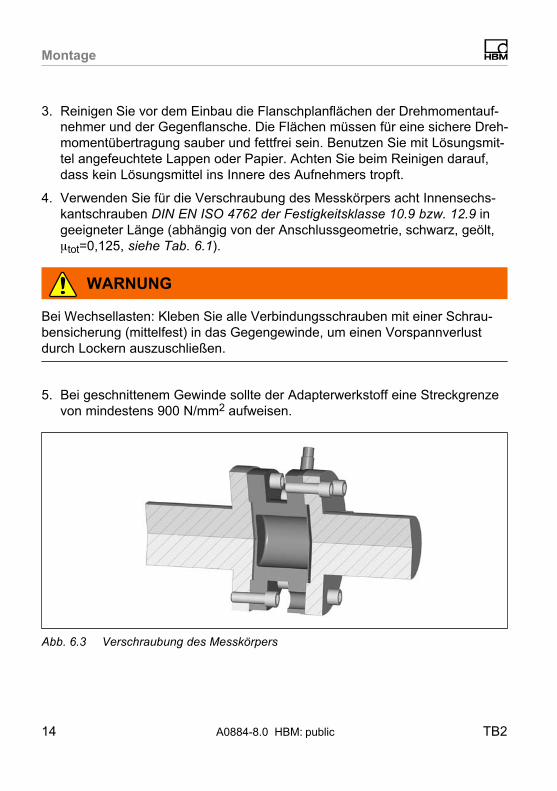
3. Prior to installation, clean the torque transducer flange and counterflangeplane surfaces. For safe torque transfer, the surfaces must be clean andfree from grease. Use a piece of cloth or paper soaked in solvent. Makesure that no solvent drips into the inside of the transducer when cleaning.
4. For the bolted measuring body connection, use eight DIN EN ISO 4762
property class 10.9 or 12.9 hexagon socket screws of a suitable length (dependent on the connection geometry, black, oiled, �tot=0.125, see Tab. 6.1).
WARNING
With alternating loads: Cement all connection screws into the mating threadwith a screw locking device (medium strength) to exclude prestressing loss dueto screw slackening.
5. The adapter material should have a yield point of minimum 900 N/mm2 fortapped threads.
Fig. 6.3 Bolted connection of measuring body
6. Fasten all screws with the specified torque (Tab. 6.1).

Mounting
14 A0884-8.0 HBM: public TB2
7. For further mounting of the shaft train, there are eight tapped holes on theconnection flange. Also use screws of property class 10.9 (or 12.9) and fasten with the torque specified in Tab. 6.1.
CAUTION
With alternating loads, use a screw locking device to cement the connectingscrews into place! Guard against contamination from varnish fragments.
Nominal (rated)
torque
(N�m)
Fastening
screws (Z)1)Fastening bolts
Property class
Prescribed tight
ening torque
(N�m)
100 M8
10.9
34
200 M8 34
500 M10 67
1k M10 67
2k M12 115
3k M12 135
5k M14 12.9 220
10k M16 340
1) DIN EN ISO 4762; black/oiled/�tot = 0.125
Tab. 6.1 Fastening screws
Installation as transfer transducer
Transfer transducers must be as insensitive as possible against all installationinfluences. This can be achieved in construction through, for example, speciallydesigned adaptation flanges. This means that deviating adaptation conditions,compared to the original calibration at the manufacturer, can be minimized.
The following points must be noted in addition to the previously mentioned recommendations for reference transducer, in order to ensure optimal transfer ofsensitivity:

Mounting
TB2 A0884-8.0 HBM: public 15
� Apply the torque from inside (DI) to outside (DA) in the torque transducer,
the ratio should be DI
DA
� 0.6.
� The width of the adaptation flange (B) on the reaction side should be 1.5 to2 times the flange screw diameter.
� The adaptation flange should not be weakened by additional holes in thearea of the torque application surfaces.
DIDA
TB2 measuring side Adaptation flange
B
Fig. 6.4 Adaptation flange transfer transducer
For optimal transfer measurement results, please use:
� 225 Hz amplifier
� Extension with six‐wire circuit
6.5 Loading capacity
The torque reference transducers are suitable for measuring static and dynamic torques.
Please note, when measuring dynamic torques:

Mounting
16 A0884-8.0 HBM: public TB2
� The calibration performed for static torques is also valid for dynamic torquemeasurements.
� The natural frequency f0 for the mechanical measuring system depends onthe moments of inertia J1 and J2 of the connected rotating masses and theTB2's torsional stiffness.
Use the equation below to approximately determine the natural frequency f0 ofthe mechanical measuring arrangement:
f0 �� 12�
� ·� cT�·�1J1
� � 1J2
�� f0 = natural frequency in HzJ1, J2 = mass moment of inertia in kg⋅m2
cT = torsional stiffness in N⋅m/rad
� The oscillation width (peak‐to‐peak) can be max. 200 % (for nominal (rated)torques 3 to 10 kN⋅m=160 %) of the nominal (rated) torque designated forthe TB2, even under alternating load. The oscillation width must fall withinthe loading range specified by -MN and +MN.
CAUTION
The mechanical limit values must be complied with even in a resonance situation. The torsional spring stiffness and inertia torque for estimating the naturalfrequency can be found in Chap. 11.

Mounting
TB2 A0884-8.0 HBM: public 17
+MN 100 %
-MN 100 %
0
90
70
Nominal (rated) torque MN in %
200 % (160 %) MN
Oscillation width
Fig. 6.5 Permissible dynamic loading

Electrical connection
18 A0884-8.0 HBM: public TB2
7 Electrical connection
The torque reference transducer is supplied with a ready‐made 6‐wire transducer connection cable with free ends. A plug can be attached on request .
Extension cables should be shielded and low capacitance. HBM provides specific cables for this purpose, the 1‐KAB0304A‐10 (ready‐made) and theKAB8/00‐2/2/2 (by the meter, can also be supplied with mounted device connecting plugs).
The pin assignment can be found in the following table:
Connection PIN Wire
color
Connecting to an amplifier with
15‐pin
SUB-D con
nector
Plug
MS3106
PEMV
15‐pin SUB-
HD connector
(QuantumX)
Measurement signal(+UA)
6 wh(white)
8 A 5
Bridge excitation voltage (-UB)
1 bk(black)
5 B 2
Bridge excitation voltage (+UB)
5 bu (blue) 6 C 3
Measurement signal(-UA)
3 rd (red) 15 D 10
Sense lead (-) 2 gy (gray) 12 G 7
Sense lead (+) 4 gn(green)
13 F 8
Shielding connectedto enclosure ground
Tab. 7.1 Pin assignment
For pin assignments of amplifiers with solder or clamped connections, pleaserefer to the documentation of the applicable amplifier.

Electrical connection
TB2 A0884-8.0 HBM: public 19
16
5
4 3
2
Top view (from outside)
Device plug type EGG
Fig. 7.1 HBM pin assignment type Lemo® socket torque transducer
As connector use the Lemo® type FGG6.

Electrical connection
20 A0884-8.0 HBM: public TB2
7.1 General information
To make the electrical connection between the torque transducer and the amplifier, we recommend using shielded, low‐capacitance measurement cablesfrom HBM.
With cable extensions, make sure that there is a proper connection with minimum contact resistance and good insulation. All plug connections or swivelnuts nuts must be fully tightened.
Do not route the measurement cables parallel to power lines and control circuits. If this cannot be avoided (in cable pits, for example), maintain a minimumdistance of 50 cm and also draw the measurement cable into a steel tube.
Avoid transformers, motors, contactors, thyristor controls and similar stray‐fieldsources.
CAUTION
Transducer connection cables from HBM with plugs attached are identified inaccordance with their intended purpose (Md or n). When cables are shortened,inserted into cable ducts or installed in control cabinets, this identification canget lost or become concealed. If this is the case, it is essential for the cables tobe re‐labeled!
7.2 Notes on cabling
Electrical and magnetic fields often induce interference voltages in the measuring circuit. These interferences arise primarily from power lines lying in parallelto the measuring leads, but also from contactors or electric motors in the vicinity. In addition, interference voltages can be induced galvanically, especiallythrough the grounding of the measurement chain at several points.
Please follow the instructions below:
� Use shielded, low‐capacitance HBM cables only.
Maintenance
TB2 A0884-8.0 HBM: public 21
� Do not route measurement cables parallel to power lines or control circuits.If this is not possible (in cable pits, for example), protect the measurementcable with a rigid steel conduit, for example, and keep it at least 50 cmaway from the other cables. The power lines or control circuits should betwisted (15 twists per meter).
� Avoid stray fields from transformers, motors and contact switches.
� Do not ground the transducer, amplifier and indicator more than once. Allthe devices in the measurement chain must be connected to the samegrounded conductor.
� The connection cable shielding is connected to the transducer housing.
� Connection diagram, grounding concept (Greenline).
Grounding concept (Greenline)
The cable shield is connected in accordance with the Greenline concept. Thisencloses the measurement system in a Faraday cage. Any electromagneticinterference active here does not affect the measurement signal.
In the case of interference due to differences in potential (compensating currents), the connection between operating voltage zero and the housing groundmust be separated at the amplifier and a potential equalization line establishedbetween the housing and the amplifier housing (highly flexible stranded wire,10 mm2 wire cross‐section).
8 Maintenance
The TB2 reference torque transducers are maintenance‐free.
9 Option
Degree of protection IP67 per EN 60529.

Accessories
22 A0884-8.0 HBM: public TB2
10 Accessories
To be ordered separately:
� Connection plug MS 3106 PEMV, mounted on cable
� 15‐pin D‐plug, mounted on cable
� In combination with DKD calibration certificate, Class 0.05 as per DIN51309 or EA 10/14
� Plug: Lemo FGG6: Material number 3-3312.0126
� Measurement cable by the meterHBM type KAB7.5/00-2/2/2: Material number 4-3301.0071
� Transducer connection cable for torque transducer TB2 with 6-pin Lemoplug series FGG6 and free ends, cable length: 3 m, material number:2-9268.0675
� Transducer connection cable for torque transducer TB2 with 6-pin Lemoplug series FGG6 and free ends, cable length: can be selected for lengths >3m, material number: 2-9268.0676
Specifications
TB2 A0884-8.0 HBM: public 23
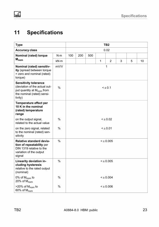
11 Specifications
Type TB2
Accuracy class 0.02
Nominal (rated) torque
Mnom
N⋅m 100 200 500
kN⋅m 1 2 3 5 10
Nominal (rated) sensitiv
ity (spread between torque= zero and nominal (rated)torque)
mV/V 1
Sensitivity tolerance
(deviation of the actual output quantity at Mnom fromthe nominal (rated) sensitivity)
% <�0.1
Temperature effect per
10 K in the nominal
(rated) temperature
range
on the output signal,related to the actual value
% <�0.02
on the zero signal, relatedto the nominal (rated) sensitivity
% <�0.01
Relative standard devia
tion of repeatability perDIN 1319 relative to thevariation of the outputsignal
% <�0.005
Linearity deviation in
cluding hysteresis
relative to the rated output(nominal)
% <�0.005
0% of Mnom to20% of Mnom
% <�0.004
>20% of Mnom to60% of Mnom
% <�0.006

Specifications
24 A0884-8.0 HBM: public TB2
Nominal (rated) torque
Mnom
500200100N⋅mNominal (rated) torque
Mnom 105321kN⋅m
>60% of Mnom to100% of Mnom
% <�0.010
Input resistance at reference temperature
Ω 1750�100
1650�100
Output resistance at reference temperature
Ω 1000 … 1500
Reference excitation
voltage
V 5
Operating range of exci
tation voltage
V 2.5 … 12
Emission as per(EN61326‐1, Table 4)
RFI field strengthClass B
Interference immunity
(EN61326‐1, Table A.1)
Electromagnetic field (AM) V/m 10
Magnetic field A/m 100
Electrostatic discharge(ESD)
Contact discharge kV 4
Air discharge kV 8
Burst (rapid transients) kV 2
Surge (impulse voltages)
kV 1
Cable based interferences
V 10
Degree of protection per
EN 60529
IP54, optional IP67
Nominal (rated) tempera
ture range
°C +10 … +60
Operating temperature
range
°C -10 … +80
Storage temperature
range
°C -50 … +85

Specifications
TB2 A0884-8.0 HBM: public 25
Nominal (rated) torque
Mnom
500200100N⋅mNominal (rated) torque
Mnom 105321kN⋅m
Mechanical shock, test
severity level per
DIN IEC 68; Part 227;
IEC 682271987
Number n 1000
Duration ms 3
Acceleration (half sine) m/s2 650
Vibrational stress
Test severity level
according to DIN IEC 68;
Part 227; IEC 68261982
Frequency range Hz 5 ... 65
Duration h 1.5
Acceleration (amplitude) m/s2 50
Load limits1)
Limit torque
related to Mnom
% 200 160
Breaking torque
related to Mnom
% >400 >320
Longitudinal limit force kN 5 10 16 19 39 42 80 120
Lateral limit force kN 1 2 4 5 9 10 12 18
Limit bending moment N⋅m 50 100 200 220 560 600 800 1200
Oscillation width per
DIN 50100 (peak‐to‐peak)N⋅m 200 400 1000 2000 4000 4800 8000 16000
Mechanical values
Torsional stiffness kN⋅m/rad
230 270 540 900 2300 2600 4600 7900
Torsion angle at Mnom Degree 0.048 0.043 0.055 0.066 0.049
0.066
0.06 0.07
Stiffness in axial direc
tion, approx.
kN/mm 420 800 900 970 1000 1100 950 1600
Stiffness in radial direc
tion, approx.
kN/mm 130 290 700 840 1400 1600 1400 2500

Specifications
26 A0884-8.0 HBM: public TB2
Nominal (rated) torque
Mnom
500200100N⋅mNominal (rated) torque
Mnom 105321kN⋅m
Stiffness during the
bending moment around
a radial axis
N⋅m/rad
66 120 9500 9800 21700 22400 31400 71000
Maximum deflection at
longitudinal force limit
mm 0.02 0.03 0.05 0.1
Additional max. radial
run‐out deviation at lat
eral limit force
mm 0.01
Additional plane/parallel
deviation at bending
moment limit
mm 0.03 0.04 0.06 0.1
Mass moment of inertia
(without taking flange boltsinto account) of rotor Iv(around the longitudinal
axis)
kg⋅m2⋅10-3
1.6 2.6 5.9 19.2 37 97
Proportional mass
moment of inertia (mea
suring side)
% 56 55 52 50
Weight, approx.
(excl. cable)kg 0.7 1.7 2.4 4.9 8.3 14.6
Weight, IP67 version,
approx. (incl. cable)kg 0.9 1.9 2.6 5.1 8.5 14.8
1) Each type of irregular stress (bending moment, lateral or longitudinal force, exceeding nominal(rated) torque) can only be permitted up to its specified static load limit, provided none of theothers can occur at the same time. If this condition is not met, the limit values must be reduced. If30% of the bending limit moment and lateral limit force occur at the same time, only 40% of thelongitudinal limit force is permissible and the nominal (rated) torque must not be exceeded. Theeffects of 10% of the permissible bending moments, axial and lateral forces on the measurementresult are ≤±0.02% of the nominal (rated) torque.

Specifications
TB2 A0884-8.0 HBM: public 27
Supplementary data as per DIN 51309 or EA 10/14
Class as per DIN 51309
Rel. zero error (zero signalreturn)
% 0.05
�0.008 (typical 0.003)
Relative reproducibility
and repeatability errors
(0.2 Mnom to Mnom) for:
a constant mountingposition
a changing mountingposition
%
%
0.02 (typical 0.01)
0.03 (typical 0.02)
Hysteresis error
(0.2 Mnom to Mnom)% 0.06 (typical 0.03)

Specifications
28 A0884-8.0 HBM: public TB2
Run‐out and concentric tolerances
Internal centering
A
Axial run‐out AB
B
Hardness 46 ... 51 HRc
Surface quality of therun‐out and concentricsurfaces (A, B and AB)
0.8
Radial run‐out AB
Measuring range Axial run‐out tolerance
(mm)
Radial run‐out tolerance
(mm)
100N⋅m 0.01 0.01
200N⋅m 0.01 0.01
500N⋅m 0.01 0.01
1kN⋅m 0.01 0.01
2kN⋅m 0.02 0.02
3kN⋅m 0.02 0.02
5kN⋅m 0.02 0.02
10kN⋅m 0.02 0.02

Dim
en
sio
ns
TB
2A
0884-8
.0 HB
M: p
ublic
29
12 Dimensions
Standard version 100�Nm - 200�Nm
Transducer connection cable, 3m(Lemo FGG6 free ends)
Ø17
Ø14
30°
60°
6 x 60°= 360°
Ø14
M8Ø84
12.5°
57
6 x 60°= 360°
60°
Min. bondingradius R = 20
60°
6 x 60°= 360°30°
Ø8.2 C12
Ø8460
18184.2
Ø112
Ø99
Ø57 H
6 (
57
.02
57
.00
Ø57 H
6 (
)
56
.99
56
.98
Ø57 g
5 (
)
Ø101
2+0.4
Xs =30.00
9
Dimensions in mm (1 mm = 0.03937)Dimensions without tolerances, per DIN ISO 2768-mk

Dim
en
sio
ns
30
A0884-8
.0 HB
M: p
ublic
TB
2
Standard version 500�Nm - 1 kNm
Min. bondingradius R = 20
45°
8 x 45°= 360°
22.5°
Ø17 M10
Ø101.5
35.75°
Ø120 Ø121
+0
.02
Ø75 H
6 (
)
45°
57
Ø124
60
18 18
4.2 2+0.4
Ø17
-0.0
1-0
.02
Ø75 g
5 (
)
Xs (30)
Ø10.5C12
A
Dimensions in mm (1 mm = 0.03937)Dimensions without tolerances, per DIN ISO 2768-mk

Dim
en
sio
ns
TB
2A
0884-8
.0 HB
M: p
ublic
31
Standard version 2 kNm - 3 kNm
45°
8 x 45°= 360°
22.5°
Ø19M12
Ø130
45°
8 x 45°= 360°
45°
8 x 45°= 360°
22.5°
12.5C12
Ø13031
64
Ø187
Ø155 9
0.0
29
0.0
0Ø
90 H
6 (
)(33)
47.7
2.5
4
20 (20)2423 5
514
89
.99
89
.97
Ø90 g
5 (
)
Ø160
Ø172.5
Cente
r of
stato
r
Dimensions in mm (1 mm = 0.03937)Dimensions without tolerances, per DIN ISO 2768-mk

Dim
en
sio
ns
32
A0884-8
.0 HB
M: p
ublic
TB
2
Standard version 5 kNm
Min. bonding radius R = 20
45°
8 x 45°= 360°
22.5°
Ø22
Ø155.5
+0
.02
Ø110 H
6 (
)
A
M14
10°
Ø14
57
45°8 x 45°= 360°
A
Ø179
-0.0
1-0
.03
Ø110 g
5 (
)
Ø188
Xs (42)
Ø180
8426 26
3.2 2.8
Ø14.5C12
Dimensions in mm (1 mm = 0.03937)Dimensions without tolerances, per DIN ISO 2768-mk
Dim
en
sio
ns
TB
2A
0884-8
.0 HB
M: p
ublic
33
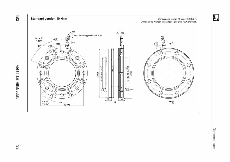
Standard version 10 kNm
Min. bonding radius R = 20
45°
8 x 45°= 360°
22.5°
Ø26
+0
.03
Ø140 H
6 (
)
10°
Ø221
-0.0
1-0
.03
Ø140 g
5 (
)
Ø222
Ø17C12
Ø230
Ø14
57M16
Ø196
45°
8 x 45°= 360°
Xs (45)
3.5+0.54.2
30 3092
A
A
Dimensions in mm (1 mm = 0.03937)Dimensions without tolerances, per DIN ISO 2768-mk

Dim
en
sio
ns
34
A0884-8
.0 HB
M: p
ublic
TB
2
Option: Degree of protection IP67, 100 Nm - 200 Nm
Min. bondingradius R = 20
Transducer connection cable,3m, free ends
Ø17
Ø14
30°
60°
6 x 60°= 360°
M8Ø84
12.5°
82
6 x 60°= 360°60°
60°
6 x 60°= 360°
30°Ø8.2C12
Ø8460
18184.2
Ø112
Ø99
57
.02
57
.00
Ø57 H
6 (
)
56
.99
56
.98
Ø57 g
5 (
)
Ø101
2+0.4
Xs =30
9
Dimensions in mm (1 mm = 0.03937)Dimensions without tolerances, per DIN ISO 2768-mk

Dim
en
sio
ns
TB
2A
0884-8
.0 HB
M: p
ublic
35
Option: Degree of protection IP67, 500 Nm - 1 kNm
Min. bondingradius R = 20
45°
8 x 45°= 360°
22.5°
Ø17
+0
.02
Ø75 H
6 (
)
35.75°
-0.0
1-0
.02
Ø75 g
5 (
)
Ø121
Ø10.5C12
Ø124
Ø17
80M10
Ø101.5
45°
8 x 45°= 360°
Xs (30)
2+0.44.2
18 18
60
A
AØ
120
Dimensions in mm (1 mm = 0.03937)Dimensions without tolerances, per DIN ISO 2768-mk

Dim
en
sio
ns
36
A0884-8
.0 HB
M: p
ublic
TB
2
Option: Degree of protection IP67, 2 kNm - 3 kNm
Min. bondingradius R = 20
45°
8 x 45°= 360°
22.5°
Ø19
+0
.02
Ø90 H
6 (
)
35°
-0.0
1-0
.03
Ø90 g
5 (
)
Ø156
Ø12.5C12
Ø160
Ø17
80M12
Ø130
45°
8 x 45°= 360°
Xs (32)
2.5+0.44.2
20 2064
A
A
Ø155
Dimensions in mm (1 mm = 0.03937)Dimensions without tolerances, per DIN ISO 2768-mk

Dim
en
sio
ns
TB
2A
0884-8
.0 HB
M: p
ublic
37
Option: Degree of protection IP67, 5 kNm
Min. bonding radius R = 20
45°
8 x 45°= 360°
22.5°
Ø22
+0
.02
Ø110 H
6 (
)
10°
-0.0
1-0
.03
Ø110 g
5 (
)
Ø180
Ø14.5C12
Ø188
Ø17
80
M14
Ø155.5
45°
8 x 45°= 360°
Xs (42)
2.83.2
26 2684
A
A
Ø179
Dimensions in mm (1 mm = 0.03937)Dimensions without tolerances, per DIN ISO 2768-mk

Dim
en
sio
ns
38
A0884-8
.0 HB
M: p
ublic
TB
2
Option: Degree of protection IP67, 10 kNm
Min. bonding radius R = 20
45°
8 x 45°= 360°
22.5°
Ø26
+0
.03
Ø140 H
6 (
)
10°
-0.0
1-0
.03
Ø140 g
5 (
)
Ø222
Ø17C12
Ø230
Ø17
80
M16
Ø196
45°8 x 45°= 360°
Xs (46)
3.5+0.54.2
30 30
92
A
A
Ø221
Dimensions in mm (1 mm = 0.03937)Dimensions without tolerances, per DIN ISO 2768-mk

Mounting Instructions | Montageanleitung
English Deutsch
TB2

2 A0884-8.0 HBM: public TB2
Deutsch
1 Sicherheitshinweise 3. . . . . . . . . . . . . . . . . . . . . . . . . . . . . . . . . . . . . .
2 Verwendete Kennzeichnungen 5. . . . . . . . . . . . . . . . . . . . . . . . . . . . .
2.1 In dieser Anleitung verwendete Kennzeichnungen 5. . . . . . . . . . . . . .
2.2 Auf dem Gerät angebrachte Symbole 6. . . . . . . . . . . . . . . . . . . . . . . . .
3 Lieferumfang 7. . . . . . . . . . . . . . . . . . . . . . . . . . . . . . . . . . . . . . . . . . . . .
4 Anwendung 8. . . . . . . . . . . . . . . . . . . . . . . . . . . . . . . . . . . . . . . . . . . . . .
5 Aufbau und Wirkungsweise 9. . . . . . . . . . . . . . . . . . . . . . . . . . . . . . .
6 Montage 10. . . . . . . . . . . . . . . . . . . . . . . . . . . . . . . . . . . . . . . . . . . . . . . . .
6.1 Allgemeine Einbauhinweise 10. . . . . . . . . . . . . . . . . . . . . . . . . . . . . . . . . .
6.2 Einbaulage 12. . . . . . . . . . . . . . . . . . . . . . . . . . . . . . . . . . . . . . . . . . . . . . . .
6.3 Bedingungen am Einbauort 12. . . . . . . . . . . . . . . . . . . . . . . . . . . . . . . . . .
6.4 Mechanischer Einbau 13. . . . . . . . . . . . . . . . . . . . . . . . . . . . . . . . . . . . . . .
6.5 Belastbarkeit 17. . . . . . . . . . . . . . . . . . . . . . . . . . . . . . . . . . . . . . . . . . . . . .
7 Elektrischer Anschluss 19. . . . . . . . . . . . . . . . . . . . . . . . . . . . . . . . . . . .
7.1 Allgemeine Hinweise 21. . . . . . . . . . . . . . . . . . . . . . . . . . . . . . . . . . . . . . .
7.2 Hinweise für die Verkabelung 21. . . . . . . . . . . . . . . . . . . . . . . . . . . . . . . .
8 Wartung 22. . . . . . . . . . . . . . . . . . . . . . . . . . . . . . . . . . . . . . . . . . . . . . . . . .
9 Option 23. . . . . . . . . . . . . . . . . . . . . . . . . . . . . . . . . . . . . . . . . . . . . . . . . . .
10 Zubehör 23. . . . . . . . . . . . . . . . . . . . . . . . . . . . . . . . . . . . . . . . . . . . . . . . . .
11 Technische Daten 24. . . . . . . . . . . . . . . . . . . . . . . . . . . . . . . . . . . . . . . . .
12 Abmessungen 30. . . . . . . . . . . . . . . . . . . . . . . . . . . . . . . . . . . . . . . . . . . .

Sicherheitshinweise
TB2 A0884-8.0 HBM: public 3
1 Sicherheitshinweise
Bestimmungsgemäßer Gebrauch
Der Referenz‐Drehmomentaufnehmer TB2 ist ausschließlich für Drehmomentmessaufgaben und direkt damit verbundene Steuerungs‐ und Regelungsaufgaben zu verwenden. Jeder darüber hinausgehende Gebrauch gilt als nicht bestimmungsgemäß.
Zur Gewährleistung eines sicheren Betriebes darf der Aufnehmer nur nach denAngaben in der Montageanleitung verwendet werden. Es sind zusätzlich die fürden jeweiligen Anwendungsfall erforderlichen Rechts‐ und Sicherheitsvorschriften zu beachten. Sinngemäß gilt dies auch für das Zubehör.
Der Aufnehmer ist kein Sicherheitselement im Sinne des bestimmungsgemäßen Gebrauchs. Der einwandfreie und sichere Betrieb dieses Aufnehmerssetzt sachgemäßen Transport, fachgerechte Lagerung, Aufstellung undMontage sowie sorgfältige Bedienung voraus.
Allgemeine Gefahren bei Nichtbeachten der Sicherheitshinweise
Der Aufnehmer entspricht dem Stand der Technik und ist betriebssicher. Vondem Aufnehmer können Restgefahren ausgehen, wenn er von ungeschultemPersonal unsachgemäß eingesetzt und bedient wird.
Jede Person, die mit Aufstellung, Inbetriebnahme, Wartung oder Reparaturdes Aufnehmers beauftragt ist, muss die Bedienungsanleitung und insbesondere die sicherheitstechnischen Hinweise gelesen und verstanden haben.
Restgefahren
Der Leistungs‐ und Lieferumfang des Aufnehmers deckt nur einen Teilbereichder Drehmomentmesstechnik ab. Sicherheitstechnische Belange der Drehmomentmesstechnik sind zusätzlich vom Anlagenplaner, Ausrüster oder Betreiberso zu planen, zu realisieren und zu verantworten, dass Restgefahren minimiertwerden. Jeweils existierende Vorschriften sind zu beachten. Auf Restgefahrenim Zusammenhang mit der Drehmomentmesstechnik ist hinzuweisen.

Sicherheitshinweise
4 A0884-8.0 HBM: public TB2
Umbauten und Veränderungen
Der Aufnehmer darf ohne unsere ausdrückliche Zustimmung weder konstruktivnoch sicherheitstechnisch verändert werden. Jede Veränderung schließt eineHaftung unsererseits für daraus resultierende Schäden aus.
Qualifiziertes Personal
Der Aufnehmer ist nur von qualifiziertem Personal ausschließlich entsprechendder technischen Daten in Zusammenhang mit den ausgeführten Sicherheitsbestimmungen und Vorschriften einzusetzen bzw. zu verwenden. Bei der Verwendung sind zusätzlich die für den jeweiligen Anwendungsfall erforderlichenRechts‐ und Sicherheitsvorschriften zu beachten. Sinngemäß gilt dies auch beiVerwendung von Zubehör.
Qualifiziertes Personal sind Personen, die mit Aufstellung, Montage, Inbetriebsetzung und Betrieb des Produktes vertraut sind und über die ihrer Tätigkeitentsprechende Qualifikationen verfügen.
Unfallverhütung
Entsprechend den einschlägigen Unfallverhütungsvorschriften der Berufsgenossenschaften ist nach der Montage des Aufnehmers vom Betreiber eine Abdeckung oder Verkleidung wie folgt anzubringen:
� Abdeckung oder Verkleidung dürfen nicht mitrotieren
� Abdeckung oder Verkleidung sollen sowohl Quetsch‐ und Scherstellenvermeiden als auch vor evtl. sich lösenden Teilen schützen.
� Abdeckungen und Verkleidungen müssen weit genug von den bewegtenTeilen entfernt oder so beschaffen sein, dass man nicht hindurchgreifenkann.
� Abdeckungen und Verkleidungen müssen auch angebracht sein, wenn diebewegten Teile des Aufnehmers außerhalb des Verkehrs‐ und Arbeitsbereiches von Personen installiert sind.
Von den vorstehenden Forderungen darf nur abgewichen werden, wenn dieMaschinenteile und ‐stellen schon durch den Bau der Maschine oder bereitsvorhandene Schutzvorkehrungen ausreichend gesichert sind.

Verwendete Kennzeichnungen
TB2 A0884-8.0 HBM: public 5
2 Verwendete Kennzeichnungen
2.1 In dieser Anleitung verwendete Kennzeichnungen
Wichtige Hinweise für Ihre Sicherheit sind besonders gekennzeichnet. Beachten Sie diese Hinweise unbedingt, um Unfälle und Sachschäden zu vermeiden.
Symbol Bedeutung
GEFAHRDiese Kennzeichnung weist auf eine unmittelbar
drohende gefährliche Situation hin, die – wenn dieSicherheitsbestimmungen nicht beachtet werden –Tod oder schwerste Körperverletzung zur Folge hat.
WARNUNGDiese Kennzeichnung weist auf eine mögliche
gefährliche Situation hin, die – wenn die Sicherheitsbestimmungen nicht beachtet werden – Tod oderschwere Körperverletzung zur Folge haben kann.
VORSICHTDiese Kennzeichnung weist auf eine mögliche
gefährliche Situation hin, die – wenn die Sicherheitsbestimmungen nicht beachtet werden – leichte odermittlere Körperverletzung zur Folge haben kann.
HinweisDiese Kennzeichnung weist auf eine Situation hin,die – wenn die Sicherheitsbestimmungen nichtbeachtet werden – Sachschäden zur Folge haben
kann.
Wichtig
Diese Kennzeichnung weist auf wichtige Informationen zum Produkt oder zur Handhabung des Produktes hin.
Tipp
Diese Kennzeichnung weist auf Anwendungstippsoder andere für Sie nützliche Informationen hin.
Information
Diese Kennzeichnung weist auf Informationen zumProdukt oder zur Handhabung des Produktes hin.
Hervorhebung
Siehe …
Kursive Schrift kennzeichnet Hervorhebungen imText und kennzeichnet Verweise auf Kapitel, Bilderoder externe Dokumente und Dateien.

Verwendete Kennzeichnungen
6 A0884-8.0 HBM: public TB2
BedeutungSymbol
Gerät -> Neu Fette Schrift kennzeichnet Menüpunkte sowie Dialog‐und Fenstertitel in Programmoberflächen. Pfeile zwischen Menüpunkten kennzeichnen die Reihenfolge,in der Menüs und Untermenüs aufgerufen werden
Messrate Fett‐kursive Schrift kennzeichnet Eingaben und Eingabefelder in Programmoberflächen.
2.2 Auf dem Gerät angebrachte Symbole
CE-Kennzeichnung
Mit der CE‐Kennzeichnung garantiert der Hersteller, dasssein Produkt den Anforderungen der relevantenEG‐Richtlinien entspricht (die Konformitätserklärungfinden Sie auf der Website von HBM (www.hbm.com)unter HBMdoc).
Gesetzlich vorgeschriebene Kennzeichnung zur Entsorgung
Nicht mehr gebrauchsfähige Altgeräte sind gemäß dennationalen und örtlichen Vorschriften für Umweltschutzund Rohstoffrückgewinnung getrennt von reguläremHausmüll zu entsorgen.

Lieferumfang
TB2 A0884-8.0 HBM: public 7
3 Lieferumfang
Im Lieferumfang sind enthalten:
� 1 Drehmoment‐Referenzaufnehmer
� 1 Montageanleitung
� 1 Prüfprotokoll
� 1 PVC‐Kabel 3 m lang (6poliger Lemo�-Stecker, freie Enden)

Anwendung
8 A0884-8.0 HBM: public TB2
4 Anwendung
Die Aufnehmer messen statische und dynamische Drehmomente im nichtdrehenden Betrieb. Die Nenndrehmomente liegen im Bereich von 100 N⋅m bis10 kN⋅m.
Transfer-Drehmomentaufnehmer
Hauptanwendungen sind der Transfer des Drehmomentes z. B. beim Kalibrieren von Referenzaufnehmern in Prüf- und Kalibriermaschinen und die Vergleiche der Bezugsnormale verschiedener Kalibrierlaboratorien.
Bei Transferaufnehmern ist ein hoher Grad an Vergleichbarkeit wichtig. DieVergleichbarkeit ist bei der Weitergabe des Drehmomentes ein Maß für verschiedene Beobachter, Versuchsbedingungen, Laboratorien, Einbau‐ undZeitsituationen. Daher sind bei der Weitergabe die gleichen Einbaubedingungen wie bei der Kalibrierung im Bezugsnormal herzustellen oder entsprechende Adapter mit einzukalibrieren.
Referenz-Drehmomentaufnehmer
Referenz‐Drehmomentaufnehmer werden in eine Kalibriervorrichtung eingebaut und dann wird die gesamte Kalibriereinrichtung beispielsweise mittelsTransfer‐Drehmomentaufnehmer qualifiziert oder zertifiziert. Der exakte Kennwert des Aufnehmers ist daher von untergeordneter Bedeutung.
Allgemeine Drehmomentmessungen im nichtdrehenden Betrieb
Wegen der hohen mechanischen Belastbarkeit, der zulässigen Schwingbreitevon 200 % (160 % bei 3 bis 10 kN⋅m) des Nenndrehmomentes und einer kompakten Bauform eignen sich die Aufnehmer auch hervorragend für den Einsatzin Prüfmaschinen für die Bauteilprüfung (Drehwechselbeanspruchung). Optional steht eine Ausführung in Schutzart IP67 nach EN 60529 zur Verfügung.

Aufbau und Wirkungsweise
TB2 A0884-8.0 HBM: public 9
5 Aufbau und Wirkungsweise
Der Drehmoment‐Referenzaufnehmer besteht aus einem - mit Dehnungsmessstreifen installierten - Messkörper mit flanschförmiger Drehmomenteinleitung.Die DMS sind so angeordnet, dass ein optimaler Drehmomentfluss zwischenFlansch und DMS‐Installationsstelle gewährleistet ist.

Montage
10 A0884-8.0 HBM: public TB2
6 Montage
6.1 Allgemeine Einbauhinweise
Beim Einbau des Drehmoment‐Referenzaufnehmers in Prüfstände beeinflussen die Prüfstandskomponenten (Rahmen, Kupplungen, Anschlussflansche,Verschraubungen etc.) das Verformungsverhalten im Wellenstrang und damitdie Messcharakteristik (Nullpunkt, Kennwert, Wiederholbarkeit). Ursachen hierfür können sein:
� Zusätzlich auftretende parasitäre Belastungen wie Radial‐, Axialkräfte oderBiegemomente
� Unsymmetrische Drehmomenteinleitung in den Aufnehmer
� Von der Aufnehmer‐Kalibrierung abweichende Steifigkeitsbedingungen imWellenstrang
Diese Rückwirkungen des Prüfstandes auf den Referenzaufnehmer werdenz. B. durch adaptierbare Hebel‐Masse‐Systeme einkalibriert.
Zu kalibrierenderDrehmomentaufnehmer
Blockiervorrichtung
TB2
Drehmomenterzeugung
Kalibrierprüfvorrichtung mitReferenzaufnehmer
Abb. 6.1 Beispiel für den Einbau in eine Kalibrierprüfvorrichtung

Montage
TB2 A0884-8.0 HBM: public 11
Parasitäre Belastungen
Parasitäre Belastungen entstehen durch Verspannungen im Wellenstrang. Sieführen zu einem additiven Einfluss auf das Nullsignal der Drehmomentaufnehmer (siehe technische Daten). Treten sie während einer Drehmomentbelastungauf, verursachen sie eine scheinbare Kennwertänderung.
Gegenmaßnahmen:
1. Richten Sie den Wellenstrang optimal aus (Ausrichtangaben in den technischen Daten beachten!).
Solange die zulässigen Grenzen für Biegemomente, Quer‐ und Längskräftenicht überschritten werden, sind keine besonderen Kupplungen oder andereMaßnahmen für den Einbau des Drehmoment‐Referenzaufnehmers erforderlich (die Einflüsse der parasitären Grenzbelastungen auf das Messergebnis können sich wie ca. 0,2 % des Nenndrehmomentes auswirken).
2. Ist die notwendige Ausrichtgenauigkeit nicht zu erreichen, setzen Sierückwirkungsfreie Kupplungen ein.
3. Halten Sie das Gewicht der auf den Drehmoment‐Referenzaufnehmerwirkenden Wellenabschnitte möglichst gering.
Je nach Konstruktion des Prüfstandes können Entkopplungsmaßnahmen mitdrehsteifen aber biegeweichen Drehstäben notwendig sein.
Abweichende Steifigkeitsbedingungen
Weichen die Steifigkeitsbedingungen im Wellenstrang (in der Nähe des Drehmomentaufnehmers) von den Bedingungen bei der Kalibrierung in der HBM-Kalibriereinrichtung ab, führt dies zu einer veränderten Drehmomenteinleitungin den Drehmoment‐Referenzaufnehmer.
Gegenmaßnahmen:
1. Halten Sie die vorgeschriebenen Anziehdrehmomente der Befestigungsschrauben strikt ein.
2. Verwenden Sie hochfeste oder gehärtete Adaptionskomponenten, speziellin der Nähe der Drehmomentein‐ und ausleitungen des Aufnehmers.

Montage
12 A0884-8.0 HBM: public TB2
Unsymmetrische Drehmomentverteilungen
Unsymmetrische (axial ungleichmäßige) Drehmomentverteilung im Wellenstrang kann zu Verformungen führen, die ihrerseits parasitären Belastungenverursachen.
Gegenmaßnahmen:
1. Nutzen Sie alle vorhandenen Schraubverbindungen zur Befestigung.
2. Halten Sie die vorgeschriebenen Anziehdrehmomente der Befestigungsschrauben strikt ein.
3. Vermeiden Sie unnötige Bohrungen in den Adaptionsflanschen.
4. Verwenden Sie saubere, ebene und möglichst geschliffene Flanschflächen.
5. Vermeiden Sie Drehmomentein‐ und ausleitungen direkt am Außendurchmesser des Aufnehmers.
6. Verwenden Sie Adaptionsflansche mit ausreichend großen Durchgangsbohrungen, um Formschluss der Schrauben zu vermeiden.
6.2 Einbaulage
Die Einbaulage des Drehmoment‐Referenzaufnehmers ist beliebig. Bei rechtsdrehendem Moment (im Uhrzeigersinn) steht in Verbindung mit HBM‐Messverstärkern ein positives Ausgangssignal an.
6.3 Bedingungen am Einbauort
Der Drehmoment‐Referenzaufnehmer TB2 ist in der Schutzart IP54 nachEN 60529 ausgeführt. Optional steht ein Aufnehmer in Schutzart IP67 nach EN60529 zur Verfügung. Die Aufnehmer sind vor grobem Schmutz, Staub, Öl,Lösungsmitteln und Feuchtigkeit zu schützen.
Im Betrieb sind die einschlägigen Sicherheitsbestimmungen der entsprechenden Berufsgenossenschaften zum Schutz von Personen zu beachten.

Montage
TB2 A0884-8.0 HBM: public 13
6.4 Mechanischer Einbau
Hinweis
Gehen Sie mit dem Drehmoment‐Referenzaufnehmer schonend um! Der Auf
nehmer kann durch mechanische Einwirkung (Fallenlassen), chemische Ein
flüsse (z. B. Säuren, Lösungsmittel) oder Temperatureinfluss (Heißluft, Dampf)
bleibend beschädigt werden.
Kabelanschluss nicht mit größeren Seitenkräften belasten.
Beim Einbau der Referenz‐Drehmomentaufnehmer als Vergleichsnormal inKalibrierprüfständen ist das zu messende Drehmoment von der Messseite(siehe Abb. 6.2) einzuleiten.
Messseite
B
A
Abb. 6.2 Messseite der TB2
Montagefolge
1. Entfernen Sie vor der Montage die Schutzfolie von der Außenzentrierung.
2. Verwenden Sie saubere, ebene (Planlauftoleranz 0,01 mm) und möglichstgeschliffene ( Ra< 0,8) Flanschflächen (Mindest‐Werkstoff-Streckgrenze > 900 N/mm2; Härte > 30 HRC).
Montage
14 A0884-8.0 HBM: public TB2
3. Reinigen Sie vor dem Einbau die Flanschplanflächen der Drehmomentaufnehmer und der Gegenflansche. Die Flächen müssen für eine sichere Drehmomentübertragung sauber und fettfrei sein. Benutzen Sie mit Lösungsmittel angefeuchtete Lappen oder Papier. Achten Sie beim Reinigen darauf,dass kein Lösungsmittel ins Innere des Aufnehmers tropft.
4. Verwenden Sie für die Verschraubung des Messkörpers acht Innensechskantschrauben DIN EN ISO 4762 der Festigkeitsklasse 10.9 bzw. 12.9 ingeeigneter Länge (abhängig von der Anschlussgeometrie, schwarz, geölt,�tot=0,125, siehe Tab. 6.1).
WARNUNG
Bei Wechsellasten: Kleben Sie alle Verbindungsschrauben mit einer Schraubensicherung (mittelfest) in das Gegengewinde, um einen Vorspannverlustdurch Lockern auszuschließen.
5. Bei geschnittenem Gewinde sollte der Adapterwerkstoff eine Streckgrenzevon mindestens 900 N/mm2 aufweisen.
Abb. 6.3 Verschraubung des Messkörpers
Montage
TB2 A0884-8.0 HBM: public 15
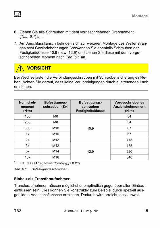
6. Ziehen Sie alle Schrauben mit dem vorgeschriebenen Drehmoment(Tab. 6.1) an.
7. Am Anschlussflansch befinden sich zur weiteren Montage des Wellenstranges acht Gewindebohrungen. Verwenden Sie ebenfalls Schrauben derFestigkeitsklasse 10.9 (bzw. 12.9) und ziehen Sie diese mit dem vorgeschriebenen Moment nach Tab. 6.1 an.
VORSICHT
Bei Wechsellasten die Verbindungsschrauben mit Schraubensicherung einkleben! Achten Sie darauf, dass keine Verunreinigungen durch austretenden Lackentstehen.
Nenndreh
moment
(N�m)
Befestigungs
schrauben (Z)2)Befestigungs
schrauben
Festigkeitsklasse
Vorgeschriebenes
Anziehdrehmoment
(N�m)
100 M8
10.9
34
200 M8 34
500 M10 67
1k M10 67
2k M12 115
3k M12 135
5k M14 12.9 220
10k M16 340
2) DIN EN ISO 4762; schwarz/geölt/�ges = 0,125
Tab. 6.1 Befestigungsschrauben
Einbau als Transferaufnehmer
Transferaufnehmer müssen möglichst unempfindlich gegenüber allen Einbaueinflüssen sein. Dies können Sie konstruktiv zum Beispiel durch speziell ausgebildete Adaptionsflansche erreichen. Dadurch wird erreicht, dass abwei

Montage
16 A0884-8.0 HBM: public TB2
chende Adaptionsbedingungen im Vergleich zur Ursprungskalibrierung beimHersteller minimiert werden.
Zum optimalen Übertragen des Kennwertes sollten ergänzend zu den schongenannte Empfehlungen für Referenzaufnehmer folgende Punkte beachtetwerden:
� Leiten Sie das Drehmoment von innen (DI) nach außen (DA) in die Drehmo
mentaufnehmer ein, wobei das Verhältnis DI
DA
� 0.6 sein sollte.
� Die Breite des Adaptionsflansches (B) auf der Reaktionsseite sollte das1,5...2‐fache des Flanschschraubendurchmessers betragen.
� Die Adaptionsflansche sollten im Bereich der Drehmomenteinleitungsflächen nicht durch zusätzliche Bohrungen geschwächt werden.
DIDA
TB2-Messseite Adaptionsflansche
B
Abb. 6.4 Adaptionsflansch Transferaufnehmer
Für optimale Transfer‐Messergebnisse verwenden Sie bitte:
� 225 Hz‐Messverstärker
� Verlängerung mit Sechsleiterschaltung

Montage
TB2 A0884-8.0 HBM: public 17
6.5 Belastbarkeit
Die Drehmoment‐Referenzaufnehmer eignen sich zum Messen statischer unddynamischer Momente.
Bitte beachten Sie beim Messen dynamischer Drehmomente:
� Die für statische Drehmomente durchgeführte Kalibrierung gilt auch fürdynamische Drehmomentmessungen.
� Die Eigenfrequenz f0 der mechanischen Messanordnung hängt von denTrägheitsmomenten J1 und J2 der angeschlossenen Drehmassen sowie derDrehsteifigkeit der TB2 ab.
Die Eigenfrequenz f0 der mechanischen Messanordnung lässt sich aus folgender Gleichung überschlägig bestimmen:
f0 �� 12�
� ·� cT�·�1J1
� � 1J2
�� f0 = Eigenfrequenz in HzJ1, J2 = Massenträgheitsmoment in kg⋅m2
cT = Drehsteifigkeit in N⋅m/rad
� Die Schwingbreite (Spitze/Spitze) darf max. 200 % (bei Nenndrehmoment 3bis 10 kN⋅m=160 %) des für die TB2 kennzeichnenden Nenndrehmomentessein, auch bei Wechsellast. Dabei muss die Schwingbreite innerhalb desdurch -MN und +MN festgelegten Belastungsbereiches liegen.
VORSICHT
Auch im Resonanzfall müssen die mechanischen Grenzwerte eingehalten werden. Drehfedersteifigkeit und Trägheitsmoment zur Abschätzung der Eigenfrequenzen können Sie Kap. 11 entnehmen.

Montage
18 A0884-8.0 HBM: public TB2
+MN 100 %
-MN 100 %
0
90
70
Nenndrehmoment MN in%
200 % (160 %) MN
Schwingbreite
Abb. 6.5 Zulässige dynamische Belastung

Elektrischer Anschluss
TB2 A0884-8.0 HBM: public 19
7 Elektrischer Anschluss
Die Drehmoment‐Referenzaufnehmer werden mit einem konfektionierten 6adrigen Aufnehmer‐Anschlusskabel mit freien Enden ausgeliefert. Auf Wunsch isteine Steckermontage möglich.
Verlängerungskabel sollten geschirmt und kapazitätsarm sein. HBM bietet hierfür speziell die Kabel 1-KAB0304A-10 (konfektioniert) und KAB8/00‐2/2/2 (Meterware, kann auch mit montiertem Geräteanschlussstecker geliefert werden)an.
Die Anschlussbelegung entnehmen Sie bitte der folgenden Tabelle:
Anschluss PIN Ader
farbe
Anschluss an einen Messverstärker mit
15-pol.
Sub‐D‐Ste
cker
Stecker
MS3106
PEMV
15-pol. Sub‐
HD‐Stecker
(QuantumX)
Messsignal (+UA) 6 ws (weiß) 8 A 5
Brückenspeisespannung (-UB)
1 sw(schwarz)
5 B 2
Brückenspeisespannung (+UB)
5 bl (blau) 6 C 3
Messsignal (-UA) 3 rt (rot) 15 D 10
Fühlerleitung (-) 2 gr (grau) 12 G 7
Fühlerleitung (+) 4 gn (grün) 13 F 8
Schirm an Gehäusemasse
Tab. 7.1 Anschlussbelegung
Anschlussbelegungen von Messverstärkern mit Löt‐ oder Klemmanschlussentnehmen Sie bitte den Unterlagen des jeweiligen Verstärkers.

Elektrischer Anschluss
20 A0884-8.0 HBM: public TB2
16
5
4 3
2
Draufsicht (von außen)
Buchse Typ EGG
Abb. 7.1 HBM PIN‐Belegung Typ Lemo�‐Buchse Drehmomentaufnehmer
Als Stecker ist der Lemo�‐Typ FGG6 zu verwenden.

Elektrischer Anschluss
TB2 A0884-8.0 HBM: public 21
7.1 Allgemeine Hinweise
Für die elektrische Verbindung zwischen Drehmomentaufnehmer und Messverstärker empfehlen wir die geschirmten und kapazitätsarmen Messkabel vonHBM zu verwenden.
Achten Sie bei Kabelverlängerungen auf eine einwandfreie Verbindung mit geringstem Übergangswiderstand und guter Isolation. Alle Steckverbindungenoder Überwurfmuttern müssen fest angezogen werden.
Verlegen Sie Messkabel nicht parallel zu Starkstrom‐ und Steuerleitungen. Istdies nicht vermeidbar (etwa in Kabelschächten), halten Sie einen Mindestabstand von 50 cm ein und ziehen Sie das Messkabel zusätzlich in ein Stahlrohrein.
Meiden Sie Trafos, Motoren, Schütze, Thyristorsteuerungen und ähnlicheStreufeldquellen.
VORSICHT
Aufnehmer‐Anschlusskabel von HBM mit montierten Steckern sind ihrem Verwendungszweck entsprechend gekennzeichnet (Md oder n). Beim Kürzen derKabel, Einziehen in Kabelkanälen oder Verlegen in Schaltschränken kanndiese Kennzeichnung verloren gehen oder verdeckt sein. Ist dies der Fall, sinddie Kabel unbedingt neu zu kennzeichnen!
7.2 Hinweise für die Verkabelung
Elektrische und magnetische Felder verursachen oft die Einkopplung von Störspannungen in den Messkreis. Diese Störungen gehen in erster Linie von parallel zu den Messleitungen liegenden Starkstromleitungen aus, aber auch vonin der Nähe befindlichen Schützen oder Elektromotoren. Außerdem könnenStörspannungen auf galvanischem Wege eingekoppelt werden, insbesonderedurch Erdung der Messkette an mehreren Punkten.
Beachten Sie bitte folgende Hinweise:

Wartung
22 A0884-8.0 HBM: public TB2
� Verwenden Sie nur abgeschirmte und kapazitätsarme Messkabel von HBM.
� Messkabel nicht parallel zu Starkstrom‐ oder Steuerleitungen verlegen.Falls dies nicht möglich ist (z. B. in Kabelschächten), schützen Sie dasMesskabel z. B. durch Stahlrohre und halten einen Mindestabstand von 50cm zu den anderen Kabeln. Starkstrom‐ oder Steuerleitungen sollten in sichverdrillt sein (15 Schlag pro Meter).
� Streufelder von Trafos, Motoren und Schützen sind zu meiden.
� Aufnehmer, Verstärker und Anzeigegerät nicht mehrfach erden. Alle Geräteder Messkette sind an den gleichen Schutzleiter anzuschließen.
� Der Schirm des Anschlusskabels ist mit dem Aufnehmergehäuse verbunden.
� Anschlussschema, Erdungskonzept (Greenline).
Erdungskonzept (Greenline)
Der Kabelschirm ist nach dem Greenline‐Konzept angeschlossen. Dadurchwird das Messsystem von einem Faradayschen Käfig umschlossen. Hierwirkende elektromagnetische Störungen beeinflussen das Messsignal nicht.
Bei Störungen durch Potentialunterschiede (Ausgleichsströme) sind am Messverstärker die Verbindungen zwischen Betriebsspannungsnull und Gehäusemasse zu trennen und eine Potential‐Ausgleichsleitung zwischen Gehäuse undMessverstärkergehäuse zu legen (hochflexible Litze, 10 mm2 Leitungsquerschnitt).
8 Wartung
Die Referenz‐Drehmomentaufnehmer TB2 sind wartungsfrei.

Option
TB2 A0884-8.0 HBM: public 23
9 Option
� Schutzart IP67 nach EN 60529
10 Zubehör
Zusätzlich zu beziehen:
� Anschlussstecker MS 3106 PEMV, an Kabel montiert
� 15poliger D‐Stecker, an Kabel montiert
� DKD‐Kalibrierschein Klasse 0,05 nach DIN 51309 oder EA 10/14
� Stecker: Lemo FGG6: Materialnummer 3-3312.0126
� Messkabel MeterwareHBM Typ KAB7.5/00-2/2/2: Materialnummer 4-3301.0071
� Aufnehmer-Anschlusskabel für Drehmomentaufnehmer TB2 mit 6-poligemLemo-Stecker Serie FGG6 und freien Enden, Kabellänge: 3 m, Materialnummer: 2-9268.0675
� Aufnehmer-Anschlusskabel für Drehmomentaufnehmer TB2 mit 6-poligemLemo-Stecker Serie FGG6 und freien Enden, Kabellänge: wählbar fürLängen >3m, Materialnummer: 2-9268.0676

Technische Daten
24 A0884-8.0 HBM: public TB2
11 Technische Daten
Typ TB2
Genauigkeitsklasse 0,02
Nenndrehmoment Mnom N⋅m 100 200 500
kN⋅m 1 2 3 5 10
Nennkennwert (Spannezwischen Drehmoment =null und Nenndrehmoment)
mV/V 1
Kennwerttoleranz (Abweichung der tatsächlichenAusgangsgröße bei Mnomvom Nennkennwert)
% <�0,1
Temperatureinfluss pro
10 K im Nenntemperatur
bereich
auf das Ausgangssignal,bezogen auf den Istwert
% <�0,02
auf das Nullsignal, bezogenauf den Nennkennwert
% <�0,01
Relative Standardabwei
chung der Wieder
holbarkeit nach DIN 1319bezogen auf die Ausgangssignaländerung
% <�0,005
Linearitätsabweichung
einschl. Hysterese, bezogen auf den Nennkennwert
% <�0,005
0% v. Mnom bis20% v. Mnom
% <�0,004
>20% v. Mnom bis60% v Mnom
% <�0,006
>60% v. Mnom bis100% v. Mnom
% <�0,010
Eingangswiderstand bei Referenztemperatur
Ω 1750�100
1650�100

Technische Daten
TB2 A0884-8.0 HBM: public 25
Nenndrehmoment Mnom 500200100N⋅m
105321kN⋅m
Ausgangswiderstand
bei ReferenztemperaturΩ 1000 … 1500
Referenzspeisespannung V 5
Gebrauchsbereich der
Speisespannung
V 2,5 … 12
Emission nach(EN 61326-1, Tabelle 4)
FunkstörfeldstärkeKlasse B
Störfestigkeit (EN 61326-1,Tabelle A.1)
Elektromagnetisches Feld(AM)
V/m 10
Magnetisches Feld A/m 100
Elektrostatische Entladung(ESD)
Kontaktentladung kV 4
Luftentladung kV 8
Burst (schnelle Transienten)
kV 2
Surge (Stoßspannungen)
kV 1
LeitungsgebundeneStörungen
V 10
Schutzart nach EN 60 529 IP54, optional IP67
Nenntemperaturbereich °C +10 … +60
Gebrauchstemperatur
bereich°C -10 … +80
Lagerungstemperatur
bereich°C -50 … +85
Technische Daten
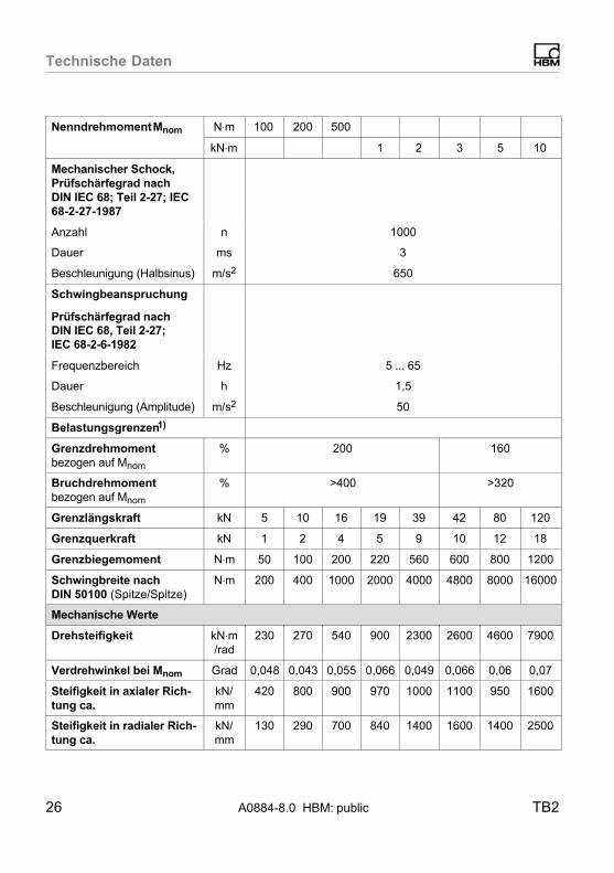
26 A0884-8.0 HBM: public TB2
Nenndrehmoment Mnom 500200100N⋅m
105321kN⋅m
Mechanischer Schock,
Prüfschärfegrad nach
DIN IEC 68; Teil 2‐27; IEC
68‐2‐27‐1987
Anzahl n 1000
Dauer ms 3
Beschleunigung (Halbsinus) m/s2 650
Schwingbeanspruchung
Prüfschärfegrad nachDIN IEC 68, Teil 2‐27;
IEC 68‐2‐6‐1982
Frequenzbereich Hz 5 ... 65
Dauer h 1,5
Beschleunigung (Amplitude) m/s2 50
Belastungsgrenzen1)
Grenzdrehmoment
bezogen auf Mnom
% 200 160
Bruchdrehmoment
bezogen auf Mnom
% >400 >320
Grenzlängskraft kN 5 10 16 19 39 42 80 120
Grenzquerkraft kN 1 2 4 5 9 10 12 18
Grenzbiegemoment N⋅m 50 100 200 220 560 600 800 1200
Schwingbreite nach
DIN�50�100 (Spitze/Spitze)N⋅m 200 400 1000 2000 4000 4800 8000 16000
Mechanische Werte
Drehsteifigkeit kN⋅m/rad
230 270 540 900 2300 2600 4600 7900
Verdrehwinkel bei Mnom Grad 0,048 0,043 0,055 0,066 0,049 0,066 0,06 0,07
Steifigkeit in axialer Rich
tung ca.
kN/mm
420 800 900 970 1000 1100 950 1600
Steifigkeit in radialer Rich
tung ca.
kN/mm
130 290 700 840 1400 1600 1400 2500

Technische Daten
TB2 A0884-8.0 HBM: public 27
Nenndrehmoment Mnom 500200100N⋅m
105321kN⋅m
Steifigkeit bei
Biegemoment um eine
radiale Achse
N⋅m/rad
66 120 9500 9800 21700 22400 31400 71000
Maximale Auslenkung bei
Grenzlängskraft
mm 0,02 0,03 0,05 0,1
Zusätzlicher max. Rund
lauffehler bei Grenzquer
kraft
mm 0,01
Zusätzliche Plan
parallelitätsabweichung
bei Grenzbiegemoment
mm 0,03 0,04 0,06 0,1
Massenträgheitsmoment
(ohne Berücksichtigung derFlanschschrauben) des
Rotors Iv (um Längsachse)
kg⋅m2⋅10-3
1,6 2,6 5,9 19,2 37 97
Anteiliges Massenträg
heitsmoment
(Messseite)
% 56 55 52 50
Gewicht, ca.
(ohne Kabel)kg 0,7 1,7 2,4 4,9 8,3 14,6
Gewicht IP67‐Version, ca.
(mit Kabel)kg 0,9 1,9 2,6 5,1 8,5 14,8
1) Jede irreguläre Beanspruchung (Biegemoment, Quer‐ oder Längskraft, Überschreiten desNenndrehmomentes) ist bis zu der angegebenen Grenze nur dann zulässig, solange keine derjeweils anderen von ihnen auftreten kann. Andernfalls sind die Grenzwerte zu reduzieren. Wennje 30% des Grenzbiegemomentes und der Grenzquerkraft vorkommen, sind nur noch 40% derGrenzlängskraft zulässig, wobei das Nenndrehmoment nicht überschritten werden darf. DieAuswirkungen von 10% der zulässigen Biegemomente, Längs- und Querkräfte auf dasMessergebnis sind ≤±0,02% des Nennmomentes.

Technische Daten
28 A0884-8.0 HBM: public TB2
Ergänzende Angaben nach DIN 51309 oder EA 10/14
Klasse nach DIN 51309
rel. Nullpunktabweichung(Nullsignalrückkehr)
% 0,05
�0,008 (typisch 0,003)
Rel. Spannweite
(0,2 Mnom bis Mnom) bei
unveränderterEinbaustellung
bei veränderterEinbaustellung
%
%
0,02 (typisch 0,01)
0,03 (typisch 0,02)
Rel. Umkehrspanne
(0,2 Mnom bis Mnom)% 0,06 (typisch 0,03)

Technische Daten
TB2 A0884-8.0 HBM: public 29
Plan‐ und Rundlauftoleranzen
Innenzentrierung
APlanlauf AB
B
Härte 46 ... 51 HRc
Oberflächengüte der Plan‐und Rundlaufflächen (A, Bund AB)
0,8
Rundlauf AB
Messbereich Planlauftoleranz (mm) Rundlauftoleranz (mm)
100 N⋅m 0,01 0,01
200 N⋅m 0,01 0,01
500 N⋅m 0,01 0,01
1 kN⋅m 0,01 0,01
2 kN⋅m 0,02 0,02
3 kN⋅m 0,02 0,02
5 kN⋅m 0,02 0,02
10 kN⋅m 0,02 0,02

Ab
messu
ng
en
30
A0884-8
.0 HB
M: p
ublic
TB
2
12 Abmessungen
Standardversion 100�Nm - 200�Nm
Aufnehmer-Anschlusskabel, 3 m(Lemo FGG6 freie Enden)
Ø17
Ø14
30°
60°
6 x 60°= 360°
Ø14
M8Ø84
12,5°
57
6 x 60°= 360°
60°
Min. BiegeradiusR = 20
60°
6 x 60°= 360°30°
Ø8,2 C12
Ø8460
18184,2
Ø112
Ø99
Ø57 H
6 (
57
,02
57
,00
Ø57 H
6 (
)
56
,99
56
,98
Ø57 g
5 (
)
Ø101
2+0,4
Xs =30,00
9
Abmessungen in mmMaße ohne Toleranzangaben
nach DIN ISO 2768-mk
Ab
messu
ng
en
TB
2A
0884-8
.0 HB
M: p
ublic
31
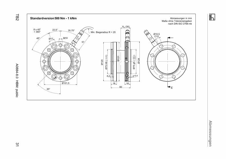
Standardversion 500�Nm - 1 kNm
Min. Biegeradius R = 20
45°
8 x 45°= 360°
22,5°
Ø17 M10
Ø101,5
35,75°
Ø120 Ø121
+0
,02
Ø75 H
6 (
)
45°
57
Ø1
24
60
18 18
4,2 2+0,4
Ø17
-0,0
1-0
,02
Ø75 g
5 (
)
Xs (30)
Ø10,5C12
A
Abmessungen in mmMaße ohne Toleranzangaben
nach DIN ISO 2768-mk

Ab
messu
ng
en
32
A0884-8
.0 HB
M: p
ublic
TB
2
Standardversion 2 kNm - 3 kNm
45°
8 x 45°= 360°
22,5°
Ø19M12
Ø130
45°
8 x 45°= 360°
45°
8 x 45°= 360°
22,5°
12,5C12
Ø13031
64
Ø187
Ø155 9
0,0
29
0,0
0Ø
90 H
6 (
)
(33)47,7
2,5
4
20 (20)2423 5
514
89
,99
89
,97
Ø90 g
5 (
)
Ø160
Ø172,5
Sta
tor-
Mitt
e
Abmessungen in mmMaße ohne Toleranzangaben
nach DIN ISO 2768-mk

Ab
messu
ng
en
TB
2A
0884-8
.0 HB
M: p
ublic
33
Standardversion 5 kNm
Min. Biegeradius R = 20
45°
8 x 45°= 360°
22,5°
Ø22
Ø155,5
+0
,02
Ø110 H
6 (
)
A
M14
10°
Ø14
57
45°8 x 45°= 360°
A
Ø179
-0,0
1-0
,03
Ø110 g
5 (
)
Ø188
Xs (42)
Ø180
8426 26
3,2 2,8
Ø14,5C12
Abmessungen in mmMaße ohne Toleranzangaben
nach DIN ISO 2768-mk

Ab
messu
ng
en
34
A0884-8
.0 HB
M: p
ublic
TB
2
Standardversion 10 kNm
Min. Biegeradius R = 20
45°
8 x 45°= 360°
22,5°
Ø26
+0
,03
Ø140 H
6 (
)
10°
Ø221
-0,0
1-0
,03
Ø140 g
5 (
)
Ø222
Ø17C12
Ø230
Ø14
57M16
Ø196
45°
8 x 45°= 360°
Xs (45)
3,5+0,54,2
30 3092
A
A
Abmessungen in mmMaße ohne Toleranzangaben
nach DIN ISO 2768-mk

Ab
messu
ng
en
TB
2A
0884-8
.0 HB
M: p
ublic
35
Option: Schutzart IP67, 100 Nm - 200 Nm
Min. BiegeradiusR = 20
Aufnehmer-Anschlusskabel,3 m, freie Enden
Ø17
Ø14
30°
60°
6 x 60°= 360°
M8Ø84
12,5°
82
6 x 60°= 360°60°
60°
6 x 60°= 360°
30°Ø8,2C12
Ø8460
18184,2
Ø112
Ø99
57
,02
57
,00
Ø57 H
6 (
)
56
,99
56
,98
Ø57 g
5 (
)
Ø101
2+0,4
Xs =30
9
Abmessungen in mmMaße ohne Toleranzangaben
nach DIN ISO 2768-mk

Ab
messu
ng
en
36
A0884-8
.0 HB
M: p
ublic
TB
2
Option: Schutzart IP67, 500 Nm - 1 kNm
Min. BiegeradiusR = 20
45°
8 x 45°= 360°
22,5°
Ø17
+0
,02
Ø75 H
6 (
)
35,75°
-0,0
1-0
,02
Ø75 g
5 (
)
Ø121
Ø10,5C12
Ø124
Ø17
80M10
Ø101,5
45°
8 x 45°= 360°
Xs (30)
2+0,44,2
18 18
60
A
AØ
120
Abmessungen in mmMaße ohne Toleranzangaben
nach DIN ISO 2768-mk

Ab
messu
ng
en
TB
2A
0884-8
.0 HB
M: p
ublic
37
Option: Schutzart IP67, 2 kNm - 3 kNm
Min. BiegeradiusR = 20
45°
8 x 45°= 360°
22,5°
Ø19
+0
,02
Ø90 H
6 (
)
35°
-0,0
1-0
,03
Ø90 g
5 (
)
Ø156
Ø12,5C12
Ø160
Ø17
80M12
Ø130
45°
8 x 45°= 360°
Xs (32)
2,5+0,44,2
20 2064
A
AØ
155
Abmessungen in mmMaße ohne Toleranzangaben
nach DIN ISO 2768-mk
Ab
messu
ng
en
38
A0884-8
.0 HB
M: p
ublic
TB
2
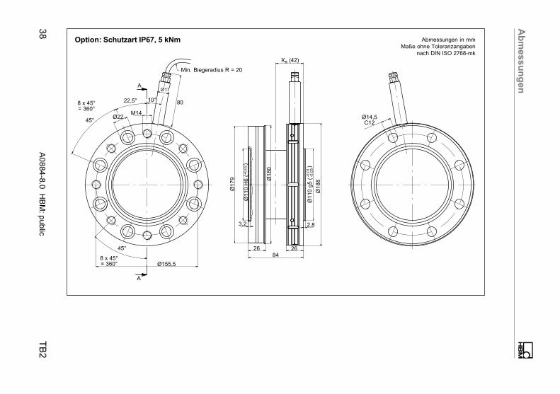
Option: Schutzart IP67, 5 kNm
Min. Biegeradius R = 20
45°
8 x 45°= 360°
22,5°
Ø22
+0
,02
Ø110 H
6 (
)
10°
-0,0
1-0
,03
Ø110 g
5 (
)
Ø180
Ø14,5C12
Ø188
Ø17
80
M14
Ø155,5
45°
8 x 45°= 360°
Xs (42)
2,83,2
26 2684
A
A
Ø179
Abmessungen in mmMaße ohne Toleranzangaben
nach DIN ISO 2768-mk

Ab
messu
ng
en
TB
2A
0884-8
.0 HB
M: p
ublic
39
Option: Schutzart IP67, 10 kNm
Min. Biegeradius R = 20
45°
8 x 45°= 360°
22,5°
Ø26
+0
,03
Ø140 H
6 (
)
10°
-0,0
1-0
,03
Ø140 g
5 (
)
Ø222
Ø17C12
Ø230
Ø17
80
M16
Ø196
45°8 x 45°= 360°
Xs (46)
3,5+0,54,2
30 30
92
A
A
Ø221
Abmessungen in mmMaße ohne Toleranzangaben
nach DIN ISO 2768-mk

ww
w.h
bm
.co
m
HBM Test and Measurement
Tel. +49 6151 803-0
Fax +49 6151 803-9100
measure and predict with confidence A0884-8
.0 7-2
001.0
884 H
BM
: public