movement area driver’s guide - pensacola...
TRANSCRIPT
Movement Area Driver’s Guide
1
Welcome to Pensacola International Airport! Whether you are a new employee with noexperience working in aviation or a seasoned veteran, our facility is truly a unique place thatprovides invaluable services to millions of people visiting Florida’s Gulf Coast.
Because Pensacola International Airport is distinct and configured unlike any other airport in theworld, this driver’s guide consisting of site-specific information about the operationalenvironment has been developed in order to provide basic orientation. This guide has beendesigned to provide the fundamental information needed to safely drive at the airport and isintended to complement the necessary practical “hands on” training provided by your employer.Because the day-to-day working environment is ever changing, it is extremely important thatyou take the time to individually educate yourself of safety specifics, regardless of yourexperience level or background.
The most important attribute of a qualified airport driver is situational awareness based upon asolid understanding of the rules. All State and County laws which apply to the operations ofvehicles on the roads and streets in the City are applicable to vehicles operating in the AirOperations Area or AOA. Additionally, the following is a synopsis of the airport rules andregulations which specifically apply to vehicles operating on the AOA.
Section 1. DEFINITIONS
The following words and phrases when used in this manual shall have the following meanings:
1. Accident. An event which involves at least one or more vehicles, injury or propertydamage.
2. Aircraft. A device that is used or intended to be used for flight in the air.
3. Air Operations Area (AOA). Any area of the airport used or intended to be used forlanding, taking off or surface maneuvering of aircraft within the Airport Security Perimeter.It is intended for use by persons for the operation of aircraft, ground support vehicles, andother authorized vehicles related to airport operations, and includes all exclusive leaseholdareas as well as the Tug Drive.
4. Airport. Pensacola International Airport, a public airport under the supervision and controlof the City of Pensacola, and located in the County of Escambia and State of Florida.
5. Airport Badging Office (ABO). The office that is responsible for Driver’s training, testing,licensing and/or administration of this procedure. In addition, documentation of driver’straining tests are maintained here.
6. Airport Director. The administrative officer or the officer's designee and, for purposes ofthe control of vehicles and enforcement of this procedure, the department head of the Cityof Pensacola in charge of the airport.
7. Airport Operations Center (AOC). The central office that handles items including trackingflights, security issues, emergency calls, dispatching police/maintenance/operations,inputting work orders and customer service for internal and external customers.
8. Air Traffic Control Tower (ATCT). A central operations facility in the air traffic controlsystem, consisting of a tower cab, including an associated room using air/groundcommunications and/or radar, visual signaling and other devices, to provide safe andexpeditious movement of terminal air traffic. This facility is operated by the FederalAviation Administration (FAA), and is commonly referred to as the Tower.
Movement Area Driver’s Guide
2
9. Authorized Emergency Vehicle. Any of the following vehicles when equipped andidentified according to law: (1) a vehicle of a fire department; (2) a publicly-owned policevehicle or a privately-owned vehicle used by a police officer for police work; (3) a publiclyor privately owned licensed emergency ambulance; (4) an emergency vehicle of amunicipal department or a public service corporation; (5) a vehicle designated as anAuthorized Emergency Vehicle upon a finding by the Pensacola International Airportwhereby that vehicle is necessary to the preservation of life or property or to the executionof emergency governmental functions.
10. Baggage Cart. Every non-motorized device, which is pulled by a vehicle and designed totransport aviation cargo, luggage or mail.
11. Breezeway. Two areas located under the concourse. One Breezeway is located betweenGates 1 and 3 to between Gates 2 and 4. This is where the tricherator is located. Thesecond Breezeway is located between Gates 5 and 7 to between Gates 6 and 8.
12. Designated Roadway / Motor Vehicle Lanes. Any portion of the AOA marked by twoparallel white lines designed primarily for the safe and orderly movement of vehicles.
13. Driver. The person in operating control of a vehicle.
14. Escort. Authorized person(s) in possession of a valid “NMA” or “MA” designer on theirbadge who is responsible for accompanying, monitoring, directing and controlling theactions of a person(s) on the Non-Movement Area or Movement Area who is not inpossession of a valid designation. The authorized person(s) must be accompanying theperson for performance of direct job duties.
15. Flight Crew. Pilot, flight engineer or flight navigator assigned to duty during aircraft flightarrival or departure time.
16. Foreign Object Debris (FOD). A substance or article alien to aircraft or system that haspotential to cause damage. Examples includes broken pavement, aircraft parts, tools,garbage, or any loose material lying on an apron, taxiway or runway.
17. Gate. An area of the AOA specifically designated and made available for the sole use ofparking by an Aircraft.
18. Marshaller. A person who directs aircraft as it moves to or from a gate.
19. Movement Area. All runways and taxiways. Entrance is marked with a boundary markingwith one solid yellow line and one dashed yellow line.
20. Movement Area Incursion. The crossing or entering of any open Movement Area, withoutpositive clearance from the Air Traffic Control Tower or proper escort.
21. Non-Movement Area. All parking areas, cargo areas, service roads, ramps and all thoseareas within the AOA that are not specifically designated as Movement Area.
22. Parking. The standing of a vehicle upon a street, road or highway, parking area, aircraftloading ramp, service area, runway, taxiway or feeder whether accompanied orunaccompanied by the operator.
23. Passenger Loading Bridge. A device used to enplane and deplane passengers from theaircraft door to the terminal.
24. PNS Driver’s Designator. A designator (NMA or MA) issued by the ABO authorizingpersons to operate a vehicle in the Non-Movement Area or Movement Area. Thisdesignator can be suspended or revoked for violations of this procedure.

Movement Area Driver’s Guide
3
25. PNS Representative. Any person(s) authorized by the Airport Director to direct orcoordinate driver safety at the airport, including but not limited to the Airport Operationsand Airport Police Divisions.
26. Powerback. A procedure where aircraft back up under their own power using reverseengine thrust.
27. Pushback. A procedure where aircraft back up under the power of another vehicle.
28. Ramp Areas. Portions of the airport designated and made available, temporarily orpermanently, for the loading and unloading of passengers or cargo on and off aircraft.
29. Right-of-Way. The privilege of the immediate use of a street, road, highway, gate, ramparea, taxiway or runway. In the Movement Area and Non-Movement area, aircraft alwayshave the right-of-way.
30. Runway. A defined rectangular area prepared for landing and takeoff of aircraft along itslength. This surface includes the associated safety area.
31. Runway Incursion. The entering of any runway, without positive clearance from the AirTraffic Control Tower.
32. Safety Area. A designated area abutting the edges of a runway or taxiway intended toreduce the risk of damage to an aircraft inadvertently leaving the runway or taxiway.
33. Security Perimeter. That portion of the airport which is enclosed by fencing, walls or otherbarriers and to which access is controlled through designated entry points.
34. Taxiway. A defined path used by aircraft to travel between the ramps and the runways.Taxiways have yellow paint markings and blue edge lights. Pensacola International Airporthas four taxiways, A, B, C and D.
35. Tug Drive. The roadway behind the Terminal Building used for baggage handling andparking of vehicles.
36. Vehicle. Every device upon which any person or property may be transported or drawnupon land. This includes baggage carts, trailers and any other device designed to betowed by a vehicle. Vehicle excludes aircraft except for any aircraft that is being towed oroperated by non-flight crew person(s). Aircraft taxiing operations are not covered underthis definition.

Movement Area Driver’s Guide
4
Section 2. DRIVER REQUIREMENTS AND RESPONSIBILITIES
A. Requirements1. Complete the non-movement area test.2. Possess a valid state driver’s license or a limited state driver’s license.3. Meet the identification requirements in accordance with the Airport
Security Program and be authorized for regular access to the AOAunder such security program in order to be in the AOA.
4. Complete the Movement Area test to demonstrate the driver’sknowledge of the airport, traffic and safety rules for the MA and therequirements of this manual.
5. Complete MA driver’s training at least every 12 consecutivecalendar months.
B. Responsibilities1. No driver shall operate and no person shall allow a driver to operate
a vehicle on the Movement Area without a current, valid PNS MAdesignation or be escorted by a person with a valid PNS MAdesignation.
2. Demonstrate an ability to read, speak, and understand the Englishlanguage so that he/she can communicate with controlling agencies.
3. Carry his/her state driver’s license at all times while operating on theAOA and show their license to a PNS Representative upon request.
4. No driver shall take any actions that threaten the safety of PNSRepresentatives, cause harm to a PNS Representative, or interferewith the safety and efficiency of airport operations.
5. Each driver must successfully complete MA driver’s training at leastonce every 12 consecutive calendar months.
6. All drivers must immediately report all vehicle accidents to the AirportOperations Center (AOC) by calling (850) 436-5000.

Movement Area Driver’s Guide
5
Airport Diagram
Movement Area Driver’s Guide
6
Section 3. MOVEMENT AREAThe Movement Area includes all taxiways, runways and associated safety areas atPNS. Extreme caution needs to be exercised when driving on these surfaces. Taxiwaysand runways are the primary surfaces for the movement of aircraft. When driving on theMovement Area, aircraft always have the right-of-way. See “Airfield Layout” figureand Figure 1-2.
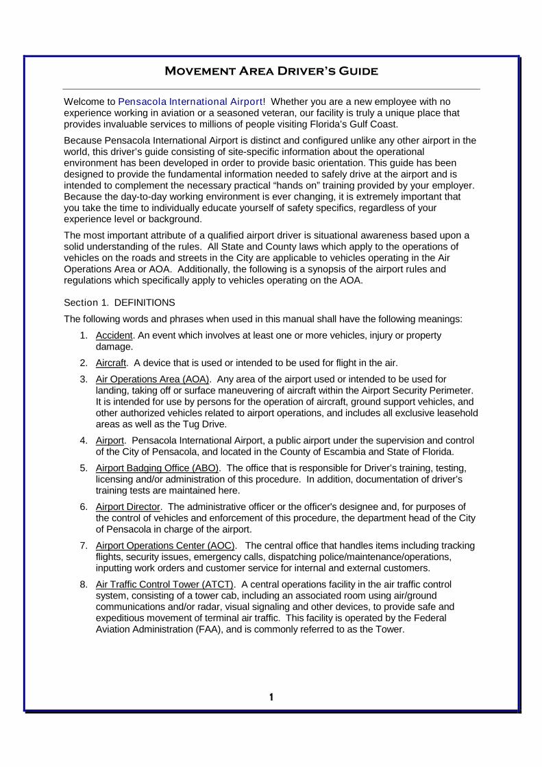
A. TaxiwaysA taxiway is a surface designed to provide access to and from the runways and otherareas of the airport, including the terminal area. Taxiways are a system of roads foraircraft by which they get to and from aprons and runways. Authorized vehicles arepermitted to drive on taxiways for emergency response, operational necessity andtraining purposes only. Driving on taxiways for point-to-point travel for the solepurposes of convenience sake and saving travel time is not permitted. Vehicles mustuse the perimeter roadway where it is available.
At PNS there are 4 taxiways:
B. Taxiway FeedersThere are points of access along the taxiways for entering and exiting the runways andramps. These points of access are called feeders. The feeders for taxiways at PNSare as follows:
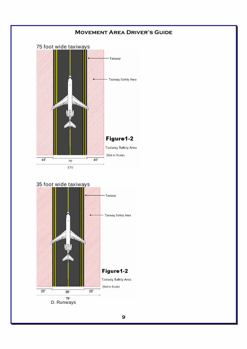
C. Taxiway Safety AreasTaxiways Alpha and Bravo at PNS are 75 feet while taxiways Charlie and Delta are 35feet wide. All taxiways at PNS have a Safety Area surrounding them. The safety areais an area provided to minimize the probability of serious damage to aircraftaccidentally entering these areas. All vehicle operators need to be aware that theseareas exist and should use caution when operating in and around them. The safetyarea should be visualized as an imaginary surface centered directly over the taxiway.These areas are either 79 or 171 feet wide. This means that if the taxiway is 75 feetwide and the safety area is 171 feet wide, the safety area extends out 85.5 feet fromthe taxiway centerline.
A – Alpha
B – Bravo
C – Charlie
D – Delta
A – A1, A2, A3, A4, A5, A6, A7
B – B1, B2, B3, B4, B5, B6, B7, B8
C – C1, C2
D – D1, D2, D3, D4, D5
Movement Area Driver’s Guide
7
Movement Area Driver’s Guide
8
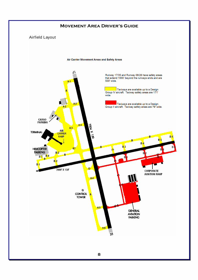
Airfield Layout
Movement Area Driver’s Guide
9
75 foot wide taxiways
35 foot wide taxiways
D. Runways
Movement Area Driver’s Guide
10
D. RunwaysThere are only two pieces of pavement that make up the runways at PNS. However,since aircraft can depart and arrive from both ends, there are four runway designators.Prior to entry onto any runway, positive communications contact needs to beestablished with the ATCT. Without authorization, entry onto a runway is prohibitedand is considered a runway incursion. Vehicles are permitted to cross open runwaysonly for emergency response, operational necessity and training. These restrictionsapply to all open runways at PNS. Runway crossings for point-to-point travel for thesole purposes of convenience sake and saving travel time are not permitted, even ifthe runway is closed. Vehicles must use the perimeter roadway where it is available.
A runway is a rectangular area prepared for landing and takeoff of aircraft. AtPNS there are two runways and four runway ends: 17, 35, 08 and 26.
Runway NumberingA runway is usually aligned with the prevailing winds. Runways arenumbered in relation to their magnetic heading, rounded off to the nearest10 degrees. For example, runway 17 is numbered this way because it is170 degrees, +/- 5 degrees, from magnetic north. Runway 35 is 350degrees, +/- 5 degrees, from magnetic north and is exactly 180 degreesfrom 17. Runways 08 and 26 are 080 degrees and 260 degrees +/- 5degrees from magnetic north respectively.
Runway DimensionsRunway 17/35 is 7,004 feet long and 150 feet wide.Runway 08/26 is 7,000 feet long and 150 feet wide.
E. Runway Safety AreasAll runways have a safety area surrounding them. This Runway Safety Area is acleared, drained and graded area abutting the edges of a useable runway andsymmetrically located about the runway. The Runway Safety Area enhances thesafety of aircraft, if the runway is undershot, overrun, or an aircraft veers off of therunway. Further, it provides greater accessibility for firefighting and rescue equipmentduring incidents. Runway Safety Areas extend 250 feet in either direction from thecenterline and include symmetrical rectangles located and extending 1000 feet beyondeach end of all runways.
These areas should not be entered at any time unless the vehicle has clearancefrom the ATCT. (See Figure 1-3.)

Movement Area Driver’s Guide
11
Movement Area Driver’s Guide
12
Section 4. MOVEMENT AREA INCURSIONS (SURFACE INCIDENT)
DEFINITION: The entering of the Movement Area without authorization.
ACTION: Immediate loss of Movement Area driving privileges for a minimum of24 hours.
PROCEDURES: The following steps will be taken after a reported Movement AreaIncursion:
1. Airport Operations is notified of the Movement Area Incursion.2. Airport Operations advises the driver and the driver’s supervisor of the
incursion and conducts an investigation.3. Airport Operations reviews the events leading to the incursion with the
driver.4. The results of the investigation are sent to the Airport Director with a copy
to the driver’s supervisor.5. The Airport Director determines if a penalty should be imposed.
When persons fail to comply with these procedures, even if a runway incursion didnot occur, the Airport Director can impose penalties. Penalties may not be limited tovehicle operator(s) only.
A. Runway IncursionsThe following is from the FAA’s Runway Safety Program website:
“Runway safety is one of the FAA’s highest priorities – specifically the problem of runwayincursions. A runway incursion is defined as: Any occurrence at an airport involving anaircraft, vehicle or person on the ground that creates a collision hazard or results in a lossof separation with an aircraft taking off, intending to take off, landing or intending to land.
Though relatively few in number when compared to the massive amount of traffic thatmoves safely through our nation’s airports every day, runway incursions present a specialproblem. Not only do they have the potential to put more lives at risk due to the numberand proximity of aircraft operating on the airport surface, they also take place in acomplex and dynamic environment where root causes are difficult to isolate.
At the simplest level, incursions occur because people make mistakes. Humans aresuperbly skilled at making decisions under a wide range of circumstances but, for avariety of reasons, they are also fallible. Consider this human vulnerability within thecontext of the numerous variables that may contribute to human error and you canappreciate the problem. It’s not just a pilot, controller or vehicle operator problem, it is aproblem that all of us in the aviation community share.”
As mentioned above, the FAA defines a runway incursion as “an occurrence at anairport involving an aircraft, vehicle, person or object on the ground that createsa collision hazard or results in loss of separation with an aircraft taking off,intending to takeoff, landing or intending to land.”
A runway incursion can be and is one of the most serious offenses that a vehicleoperator may commit due to the potential catastrophic consequences that could result.For this reason, if for no others, vehicle operators must be knowledgeable of airportrules, regulations, and operating procedures. Vehicle operators should also be awareof their position and alert to their surroundings at all times.
Movement Area Driver’s Guide
13
B. Runway Incursion ProtocolIn the event that a driver realizes a runway incursion has been committed, thefollowing guidelines should be followed:
1. Clear the runway immediately and contact the ATCT to advise them of youractions.
2. Immediately notify the AOC and your supervisor of the runway incursion.
The following procedures have been implemented to report, respond to and documentrunway incursions:
1. PNS AOC is notified of the runway incursion.2. PNS AOC advises Airport Operations Staff and the Airport Police of the runway
incursion.3. Airport Operations Staff and the Airport Police respond to the runway incursion.4. Airport Operations Manager or Officer will notify the driver that his/her privileges
to operate on the AOA will be immediately suspended for a minimum of 3 days.5. The driver's supervisor will be notified immediately by Airport Operations Staff.6. The Airport Operations will review the incursion with the driver and driver’s
supervisor. Airport Operations will provide remedial training for the driver. Thedriver will be administered a written test by the Airport Operations Division’sauthorized trainers. Passing score for the test is 100% for all sections. Thosedrivers that fail any section(s) of the test will be required to take a re-test onthose sections. If the re-test is failed, then the driver will be trained to 100% ofthe test materials by any of the following methods: Written re-test, Oral re-test,Practical re-test (demonstration of knowledge).
7. The driver's AOA driving privileges will not be reactivated until at least 3 dayshave passed from the time of the incursion, remedial training and testing hasbeen completed, any penalties are served and/or the Assistant Airport Director-Operations approves the reactivation. There will be an investigation of theincursion by Airport Operations to determine all factors involved, and an attemptto identify the cause(s) of the incursion. All pertinent information will be madeavailable to the investigator(s).
8. If cause exists, the Airport Director will administer penalties to the person(s)responsible for the runway incursion.
Penalty: The Airport Director will administer penalties to the person(s) responsible forthe runway incursion. Penalties may include a loss of airfield driving privileges for aminimum of 30 days or longer and other actions as deemed necessary.
Movement Area Driver’s Guide
14
Section 5. SIGNSSigns are used at PNS to provide information to pilots when operating aircraft onrunways and taxiways. There are six basic types of signs, which are color coded forspecific uses. The six types of signs are:
1. Mandatory Instruction Signs2. Location Signs3. Direction Signs4. Destination Signs5. Taxiway Ending Markers6. Runway Distance Remaining Markers
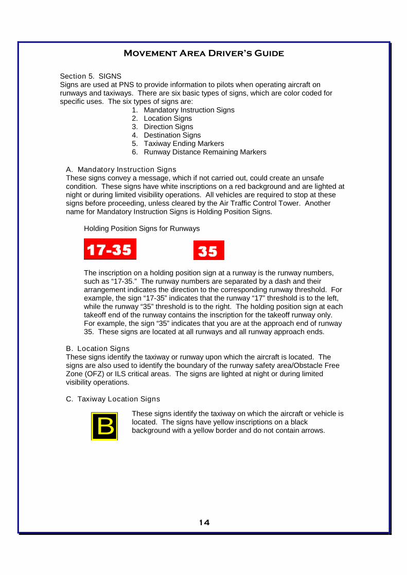
A. Mandatory Instruction SignsThese signs convey a message, which if not carried out, could create an unsafecondition. These signs have white inscriptions on a red background and are lighted atnight or during limited visibility operations. All vehicles are required to stop at thesesigns before proceeding, unless cleared by the Air Traffic Control Tower. Anothername for Mandatory Instruction Signs is Holding Position Signs.
Holding Position Signs for Runways
The inscription on a holding position sign at a runway is the runway numbers,such as “17-35.” The runway numbers are separated by a dash and theirarrangement indicates the direction to the corresponding runway threshold. Forexample, the sign “17-35” indicates that the runway “17” threshold is to the left,while the runway “35” threshold is to the right. The holding position sign at eachtakeoff end of the runway contains the inscription for the takeoff runway only.For example, the sign “35” indicates that you are at the approach end of runway35. These signs are located at all runways and all runway approach ends.
B. Location SignsThese signs identify the taxiway or runway upon which the aircraft is located. Thesigns are also used to identify the boundary of the runway safety area/Obstacle FreeZone (OFZ) or ILS critical areas. The signs are lighted at night or during limitedvisibility operations.
C. Taxiway Location Signs
These signs identify the taxiway on which the aircraft or vehicle islocated. The signs have yellow inscriptions on a blackbackground with a yellow border and do not contain arrows.B

Movement Area Driver’s Guide
15
D. Direction SignsThese signs indicate directions of other taxiways leading out of anintersection. The signs have black inscriptions on a yellowbackground and always contain arrows. The arrows are orientedto approximate the direction of the turn. The signs are lighted atnight and during limited visibility operations.
E. Destination SignsDestination signs have black inscriptions on a yellow background and always containan arrow. These signs indicate the general direction to a remote location. The signsare lighted at night or during limited visibility operations.
F. Taxiway Ending Marker
These signs indicate that a taxiway does not continue beyond anintersection. They have yellow and black diagonal stripes.Taxiway Ending Markers at PNS are located at both ends ofTaxiway D, the Taxiway D feeder at the approach end of runway26, Taxiway D3 feeder, Taxiway C1 feeder, and at end of TaxiwayC where it intersects taxiway C2.
G. Runway Distance Remaining Markers
These signs are used to provide runway distance remaininginformation to pilots when landing or taking off. They have whitenumerals on a black background and are lighted at night or duringlow visibility operations.
Each sign inscription consists of a number, which denotes theremaining distance on the runway in thousands of feet. The signsare installed at 1000 foot +/- 50 foot intervals along the side of therunway so that they can be seen from both directions
C
7
Movement Area Driver’s Guide
16
Section 6. PAVEMENT MARKINGSRunway and taxiway markings (paintings) are essential for the safe and efficient use ofthe airport. Following are the different markings for taxiways and runways.
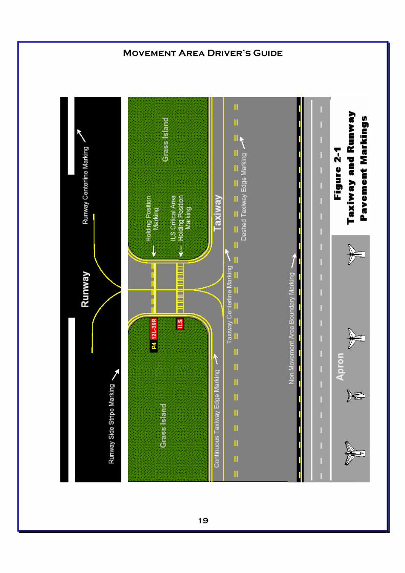
A. Taxiway Pavement MarkingsAll taxiway-marking colors are yellow. See Figure 2 – 1 for examples of all taxiwaymarkings detailed below.
Taxiway Centerline MarkingsThe taxiway centerline marking is a continuous yellow line with a minimum widthof 6 inches. On a taxiway curve, the taxiway centerline marking continues fromthe straight portion of the taxiway at a constant distance from the outside edge ofthe curve. At taxiway intersections with a runway end, the taxiway centerlinemarking is terminated at the runway edge. For taxiways crossing a runway, thetaxiway centerline marking may continue across the runway but must beinterrupted for the runway markings. Enhanced taxiway centerline markingsconsist of a parallel line of yellow dashes on either side of the taxiway centerline.Taxiway centerlines are enhanced for 150 feet prior to a runway holding positionmarking.
Taxiway Edge MarkingsTaxiway edge markings are used to delineate the edge of the taxiway. They areprimarily used when the taxiway does not correspond with the edge of thepavement. There are two types of markings used depending on whether theaircraft is supposed to cross the taxiway edge; they are continuous or dashed.
Continuous MarkingsContinuous taxiway edge markings are used to delineate the taxiwayedge from the shoulder or some other contiguous paved surface notintended for use by aircraft. The markings consist of a continuous doubleyellow line, with each line being at least six inches in width and spacedsix inches apart.
Dashed MarkingsDashed taxiway edge markings are used when there is an operationalneed to define the edge of a taxiway or taxi lane on a paved surfacewhere the pavement next to the edge is intended for use by aircraft. Themarkings consist of a broken double yellow line with each line being atleast six inches in width and spaced six inches apart. The lines are 15feet in length with gaps of 25 feet.
Non-Movement Area Boundary MarkingsNon-movement area boundary markings are used when there is a needto delineate the movement area from the non-movement area. Themarkings consist of two yellow lines (one solid and one dashed). Thesolid line is located on the non-movement area side while the dashedyellow line is located on the movement area side.
Movement Area Driver’s Guide
17
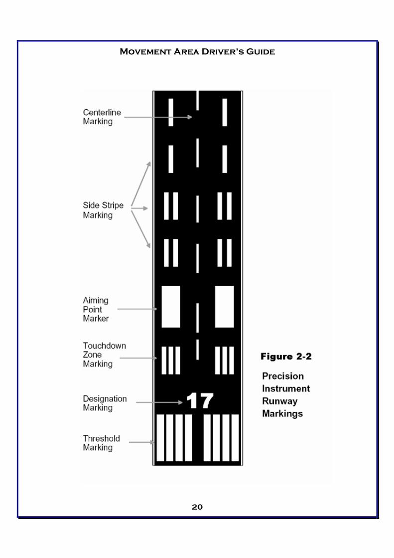
B. Runway Pavement MarkingsAll runways contain markings for precision instrument approaches. Runway markingsare always white. On light-colored runway pavements, outlining with a black border atleast 6 inches in width can increase the contrast of the markings. See Figure 2 – 2 forexamples of all runway pavement markings detailed below.
All precision instrument runways have the following marking elements:
Centerline MarkingsThe runway centerline markings are located on the centerline of the runway andconsist of a line of uniformly spaced stripes and gaps. The stripes are 120 feet inlength, and the gaps are 80 feet in length. The minimum width of the stripes for aprecision instrument runway is 3 feet.
Designation MarkingsRunways are identified by numbers that indicate the nearest 10-degreeincrement of the azimuth when on the runway centerline. The magnetic azimuthof the runway centerline is measured clockwise from the magnetic north whenviewed from the direction of approach. For example, where the magneticazimuth is 303 degrees, the runway designation marking would be 30. When amagnetic azimuth ends in the number “5,” such as 045 degrees, the runwaydesignation can be either 4 or 5. Single digits are not preceded by a zero.
Threshold MarkingsThe runway threshold is the beginning of that portion of the runway useable forlanding. The marking consists of eight longitudinal stripes of uniform dimensionsarranged symmetrically about the runway centerline. The stripes are 150 feetlong and 12 feet wide and are spaced 3 feet apart except for the center space,which is 16 feet.
Touchdown Zone MarkingsTouchdown zone markings consist of groups of one, two and three rectangularbars symmetrically arranged in pairs about the runway centerline. The stripesare 75 feet long and six feet wide. These markings denote the touchdown zoneof the runway, which is the first 3,000 feet of the runway beginning at thethreshold.
Aiming Point MarkingsThe aiming point markings are a part of the touchdown zone markings and arelocated 1000 feet from the approach end of the runway. The stripes are 30 feetwide and 150 feet long.
1. Centerline Marking2. Designation Marking3. Threshold Marking4. Aiming Point Marking5. Touchdown Zone Marking6. Side Stripes
Movement Area Driver’s Guide
18
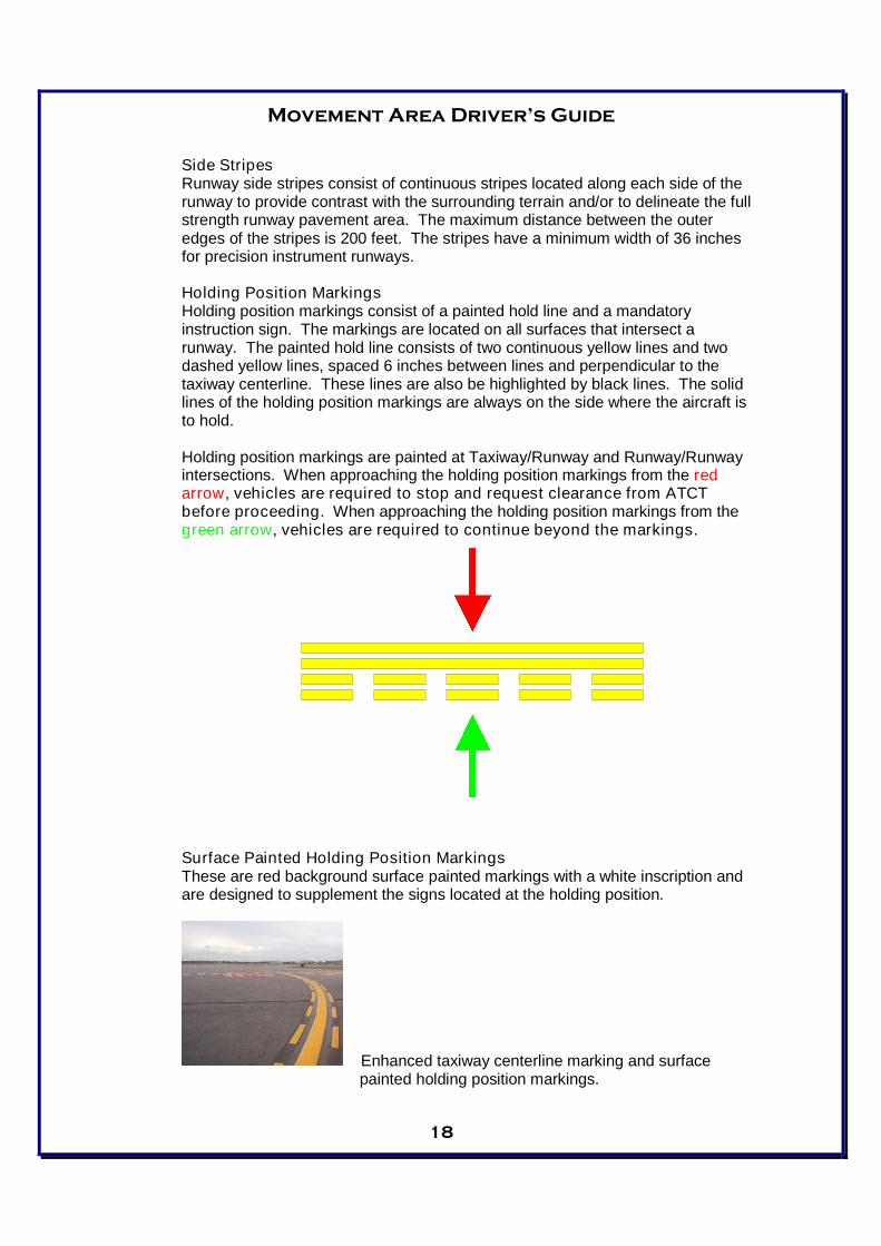
Side StripesRunway side stripes consist of continuous stripes located along each side of therunway to provide contrast with the surrounding terrain and/or to delineate the fullstrength runway pavement area. The maximum distance between the outeredges of the stripes is 200 feet. The stripes have a minimum width of 36 inchesfor precision instrument runways.
Holding Position MarkingsHolding position markings consist of a painted hold line and a mandatoryinstruction sign. The markings are located on all surfaces that intersect arunway. The painted hold line consists of two continuous yellow lines and twodashed yellow lines, spaced 6 inches between lines and perpendicular to thetaxiway centerline. These lines are also be highlighted by black lines. The solidlines of the holding position markings are always on the side where the aircraft isto hold.
Holding position markings are painted at Taxiway/Runway and Runway/Runwayintersections. When approaching the holding position markings from the redarrow, vehicles are required to stop and request clearance from ATCTbefore proceeding. When approaching the holding position markings from thegreen arrow, vehicles are required to continue beyond the markings.
Surface Painted Holding Position MarkingsThese are red background surface painted markings with a white inscription andare designed to supplement the signs located at the holding position.
Enhanced taxiway centerline marking and surfacepainted holding position markings.
Movement Area Driver’s Guide
19
Movement Area Driver’s Guide
20
Movement Area Driver’s Guide
21
Section 7. MOVEMENT AREA LIGHTINGAirport lighting allows aircraft to utilize an airport during periods of darkness or times oflow visibility. Without lights, aircraft would basically be restricted from operating atairports except when there is sunshine and blue skies. See Figures 3-1 and 3-2.
A. Taxiway Lighting
Taxiway Edge LightsThese lights are used to outline the edges of taxiways during periods of darknessor reduced visibility. All taxiway lights are blue and have 3 intensity settings; 3being the highest and 1 being the lowest.
B. Runway Lighting
Runway End Identifier Lights (RENL)RENLs consist of two synchronized white flashing lights, one on each side of therunway threshold, which provide rapid and positive identification of the approachend of a particular runway. Runways 35, 08, and 26 all have this type of lightingat PNS.
Runway Edge LightsThese lights are used to outline the edges of runways during periods of darknessor reduced visibility. These light systems are classified according to the intensityor brightness that they are capable of producing. All runway lights at PNS areHigh Intensity Runway Lights (HIRL) with 5 intensity settings; 5 being the highestand 1 being the lowest. The runway edge lights are white except where amberlights replace the white lights on the last 2,000 feet of the runway to form acaution zone
Threshold LightsThese lights mark both the approach and departure ends of the runway. Thereare two sets of four lights that emit green light out to approaching aircraft toindicate the approach end and two sets of four lights that emit red light at theopposite end of the runway to indicate the departure end.
Touchdown Zone LightsTouchdown zone lights consist of two sets of three rows of white flush mountedtransverse light bars installed in the runway pavement and located symmetricallyalong the runway centerline normally at 100 foot intervals. The basic systemextends 3,000 feet down the runway from the approach end. These lights areonly found on runway 17 at PNS.
Centerline LightsCenterline lights are flush mounted in the pavement along the centerline of therunway. Starting 75 feet from either end of the runway, they are spaced at 50foot intervals the remaining length of the runway. Runway 17/35 is the onlyrunway at PNS that has centerline lights. Each centerline light fixture has bulbson opposite sides. The lights on one side of the fixture can only be seen whenusing Runway 17 and the lights on the opposite side of the fixture can only beseen when using Runway 35. Centerline lights are white, except for the RunwayRemaining Lights on the last 3,000 feet of both 17 and 35 where they begin toalternate red and white. For the last 1,000 feet, these lights are all red.

Movement Area Driver’s Guide
22
Movement Area Driver’s Guide
23
Section 8. AIRPORT LIGHTING
A. Airport BeaconThe beacon is located on top of the Air Traffic Control Tower southwest of theintersection of the runways. The beacon is a visual navigation aid displayingalternating white and green flashes to indicate a lighted, civilian, land airport.Whenever the beacon is illuminated during daytime hours, drivers should assume thatthe airport is under instrument conditions and aircraft are using the Instrument LandingSystem (ILS). During these conditions, all drivers operating on or near the GlideslopeCritical Area and Localizer Critical Area will hold short and obtain ATCT clearancebefore entrance into these areas.
B. Obstruction LightsObstruction lighting is used to warn pilots that a hazard exists and that caution shouldbe used when moving in the area. Obstruction lights are red and are used during thehours of darkness and periods of limited visibility. Construction activities, holes,trenches, equipment and structures are all examples of where obstruction lights maybe used.
Section 9. NAVIGATION AIDS
A. Instrument Landing System (ILS)
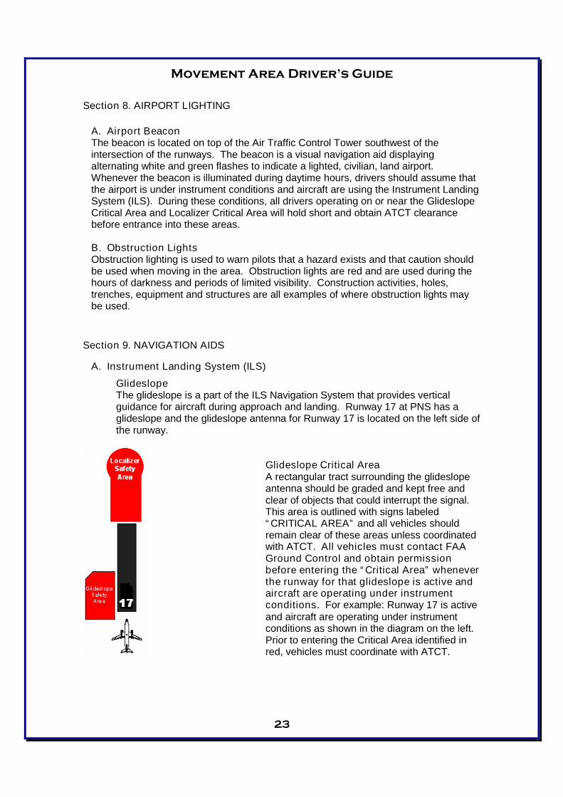
GlideslopeThe glideslope is a part of the ILS Navigation System that provides verticalguidance for aircraft during approach and landing. Runway 17 at PNS has aglideslope and the glideslope antenna for Runway 17 is located on the left side ofthe runway.
Glideslope Critical AreaA rectangular tract surrounding the glideslopeantenna should be graded and kept free andclear of objects that could interrupt the signal.This area is outlined with signs labeled“CRITICAL AREA” and all vehicles shouldremain clear of these areas unless coordinatedwith ATCT. All vehicles must contact FAAGround Control and obtain permissionbefore entering the “Critical Area” wheneverthe runway for that glideslope is active andaircraft are operating under instrumentconditions. For example: Runway 17 is activeand aircraft are operating under instrumentconditions as shown in the diagram on the left.Prior to entering the Critical Area identified inred, vehicles must coordinate with ATCT.
Movement Area Driver’s Guide
24
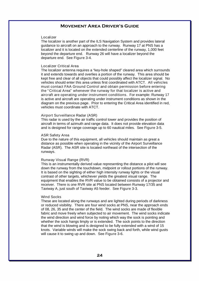
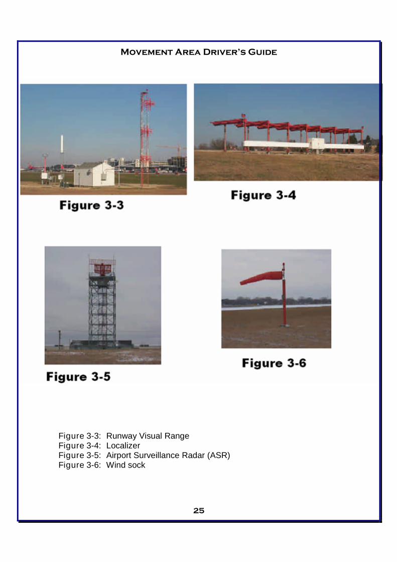
LocalizerThe localizer is another part of the ILS Navigation System and provides lateralguidance to aircraft on an approach to the runway. Runway 17 at PNS has alocalizer and it is located on the extended centerline of the runway, 1,000 feetbeyond the departure end. Runway 26 will have a localizer beyond thedeparture end. See Figure 3-4.
Localizer Critical AreaThe localizer antenna requires a “key-hole shaped” cleared area which surroundsit and extends towards and overlies a portion of the runway. This area should bekept free and clear of all objects that could possibly affect the localizer signal. Novehicles should enter this area unless first coordinated with ATCT. All vehiclesmust contact FAA Ground Control and obtain permission before enteringthe “Critical Area” whenever the runway for that localizer is active andaircraft are operating under instrument conditions. For example: Runway 17is active and aircraft are operating under instrument conditions as shown in thediagram on the previous page. Prior to entering the Critical Area identified in red,vehicles must coordinate with ATCT.
Airport Surveillance Radar (ASR)This radar is used by the air traffic control tower and provides the position ofaircraft in terms of azimuth and range data. It does not provide elevation dataand is designed for range coverage up to 60 nautical miles. See Figure 3-5.
ASR Safety AreaDue to the nature of this equipment, all vehicles should maintain as great adistance as possible when operating in the vicinity of the Airport SurveillanceRadar (ASR). The ASR site is located northeast of the intersection of therunways.
Runway Visual Range (RVR)This is an instrumentally derived value representing the distance a pilot will seedown the runway from the touchdown, midpoint or rollout portions of the runway.It is based on the sighting of either high intensity runway lights or the visualcontrast of other targets, whichever yields the greatest visual range. Theequipment that enables the RVR value to be obtained consists of a projector andreceiver. There is one RVR site at PNS located between Runway 17/35 andTaxiway A, just south of Taxiway A5 feeder. See Figure 3-3.
Wind SocksThese are located along the runways and are lighted during periods of darknessor reduced visibility. There are four wind socks at PNS, near the approach endsof 08, 26, 35 and the center of the field. The wind socks are made of flexiblefabric and move freely when subjected to air movement. The wind socks indicatethe wind direction and wind force by noting which way the sock is pointing andwhether the sock hangs limply or is extended. The sock points to the directionthat the wind is blowing and is designed to be fully extended with a wind of 15knots. Variable winds will make the sock swing back and forth, while wind gustswill cause it to swing up and down. See Figure 3-6.
Movement Area Driver’s Guide
25
Figure 3-3: Runway Visual RangeFigure 3-4: LocalizerFigure 3-5: Airport Surveillance Radar (ASR)Figure 3-6: Wind sock
Movement Area Driver’s Guide
26
Section 10. COMMUNICATIONS
In the Air Traffic Control System, radio communication is a vital link between controllers,pilots and ground vehicle operators. Proper radio communication is one of the basics forsafety, orderliness and efficiency in this system.
Comprehending or understanding directions from the controller and being certain thatthe controller understands or comprehends requests and responses are the basics forgood radio communications. This process is ensured through a system of checks andbalances.
Before making a transmission, there are several things to do. The first thing is LISTEN.Listen to the radio frequency before transmitting. If there is a conversation in progress,wait until it is completed before starting your transmission. Conversations in progresscould range from a controller issuing instructions to a pilot for taxiing, to a maintenancevehicle making a request to cross a runway.
The next thing to consider before transmitting is WHAT YOU WANT TO SAY before youstart your transmission. If you know exactly what you want to say and how you will sayit, your transmission will be more concise and understandable.
When you have been instructed by a controller to proceed with something, you shouldacknowledge that you have received and understood the instructions by repeating theinstructions and stating your call sign. If for some reason you don’t understand what thecontroller has told you, or you think that the controller does not understand what youhave said, STOP! Either confirm what the controller has told you, or clarify to thecontroller what you are requesting. You are better off to question something and fullyunderstand it, instead of proceeding forward.
When transmitting, the microphone should be close to your lips but not touching them.After you key the mike, pause for a half-second before making your transmission. Thiswill ensure that your first word is transmitted. When speaking, talk in a normalconversational tone and try not to yell, slur your words, or talk too fast.
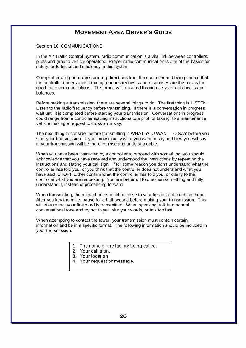
When attempting to contact the tower, your transmission must contain certaininformation and be in a specific format. The following information should be included inyour transmission:
1. The name of the facility being called.2. Your call sign.3. Your location.4. Your request or message.
Movement Area Driver’s Guide
27
An example transmission might sound like the following:
“Pensacola Ground, Ops 1 on Bravo to cross runway one seven.”
After you have made your transmission, wait a short while before attempting it again.Many times, the controllers have heard you and are attempting to either locate yourposition or are coordinating your request with another controller before giving you areply. After approximately 30 seconds, if you have not heard a reply, repeat yourtransmission. If you still don’t get a reply, check that your radio equipment is turned onand that you are transmitting on the correct frequency. While waiting for a reply orchecking your equipment, always be sure to keep an eye on the tower for light gunsignals that may be directed toward you.
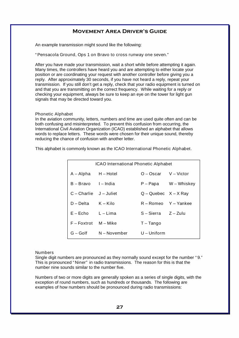
Phonetic AlphabetIn the aviation community, letters, numbers and time are used quite often and can beboth confusing and misinterpreted. To prevent this confusion from occurring, theInternational Civil Aviation Organization (ICAO) established an alphabet that allowswords to replace letters. These words were chosen for their unique sound, therebyreducing the chance of confusion with another letter.
This alphabet is commonly known as the ICAO International Phonetic Alphabet.
NumbersSingle digit numbers are pronounced as they normally sound except for the number “9.”This is pronounced “Niner” in radio transmissions. The reason for this is that thenumber nine sounds similar to the number five.
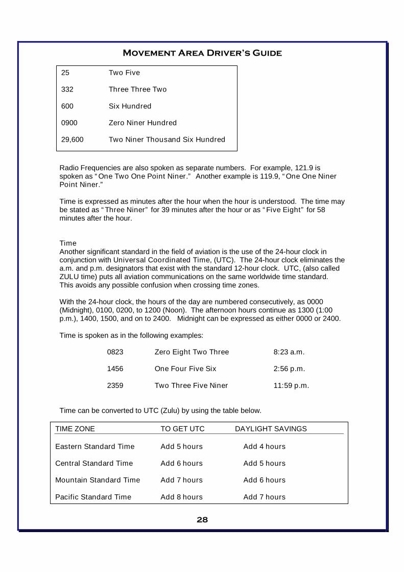
Numbers of two or more digits are generally spoken as a series of single digits, with theexception of round numbers, such as hundreds or thousands. The following areexamples of how numbers should be pronounced during radio transmissions:
ICAO International Phonetic Alphabet
A – Alpha H – Hotel O – Oscar V – Victor
B – Bravo I – India P – Papa W – Whiskey
C – Charlie J – Juliet Q – Quebec X – X Ray
D – Delta K – Kilo R – Romeo Y – Yankee
E – Echo L – Lima S – Sierra Z – Zulu
F – Foxtrot M – Mike T – Tango
G – Golf N – November U – Uniform
Movement Area Driver’s Guide
28
Radio Frequencies are also spoken as separate numbers. For example, 121.9 isspoken as “One Two One Point Niner.” Another example is 119.9, “One One NinerPoint Niner.”
Time is expressed as minutes after the hour when the hour is understood. The time maybe stated as “Three Niner” for 39 minutes after the hour or as “Five Eight” for 58minutes after the hour.
TimeAnother significant standard in the field of aviation is the use of the 24-hour clock inconjunction with Universal Coordinated Time, (UTC). The 24-hour clock eliminates thea.m. and p.m. designators that exist with the standard 12-hour clock. UTC, (also calledZULU time) puts all aviation communications on the same worldwide time standard.This avoids any possible confusion when crossing time zones.
With the 24-hour clock, the hours of the day are numbered consecutively, as 0000(Midnight), 0100, 0200, to 1200 (Noon). The afternoon hours continue as 1300 (1:00p.m.), 1400, 1500, and on to 2400. Midnight can be expressed as either 0000 or 2400.
Time is spoken as in the following examples:
0823 Zero Eight Two Three 8:23 a.m.
1456 One Four Five Six 2:56 p.m.
2359 Two Three Five Niner 11:59 p.m.
Time can be converted to UTC (Zulu) by using the table below.
Radio Checks
25 Two Five
332 Three Three Two
600 Six Hundred
0900 Zero Niner Hundred
29,600 Two Niner Thousand Six Hundred
TIME ZONE TO GET UTC DAYLIGHT SAVINGS
Eastern Standard Time Add 5 hours Add 4 hours
Central Standard Time Add 6 hours Add 5 hours
Mountain Standard Time Add 7 hours Add 6 hours
Pacific Standard Time Add 8 hours Add 7 hours
Movement Area Driver’s Guide
29
Radio ChecksOccasionally, it is desirable to ask a facility to evaluate the strength and quality of yourtransmissions. Simply say, “Radio Check, please.” A reply of “Loud and Clear”means strength and quality are good. “Weak and Clear” means strength is poor, butquality is good.
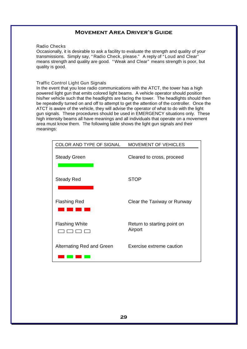
Traffic Control Light Gun SignalsIn the event that you lose radio communications with the ATCT, the tower has a highpowered light gun that emits colored light beams. A vehicle operator should positionhis/her vehicle such that the headlights are facing the tower. The headlights should thenbe repeatedly turned on and off to attempt to get the attention of the controller. Once theATCT is aware of the vehicle, they will advise the operator of what to do with the lightgun signals. These procedures should be used in EMERGENCY situations only. Thesehigh intensity beams all have meanings and all individuals that operate on a movementarea must know them. The following table shows the light gun signals and theirmeanings:
COLOR AND TYPE OF SIGNAL MOVEMENT OF VEHICLES
Steady Green Cleared to cross, proceed
Steady Red STOP
Flashing Red Clear the Taxiway or Runway
Flashing White Return to starting point onAirport
Alternating Red and Green Exercise extreme caution

Movement Area Driver’s Guide
30
Commonly Used Radio Phrases
Abeam Out from, or across from
Acknowledge Let me know that you have received andunderstood this message
Affirmative Yes
Correction An error has been made in this transmission.The correct version is…
Go Ahead Proceed with your message
How Do You Hear Me Self-explanatory
I Say Again Self-explanatory
Negative That is not correct. No.
Out This conversation is ended and no response isneeded
Read Back Repeat all of this message back to me
Roger I have received all of your last transmission(This word is used to acknowledge receipt andshall not be used for other purposes.)
Say Again Repeat your last transmission
Speak Slower Self-explanatory
Stand By If used by itself it means, “I must pause for a fewseconds.” If the pause lasts longer than a fewseconds, the transmission should be concludedand contact should be re-established later.
That Is Correct Self-explanatory
Movement Area Driver’s Guide
31
ATCT Frequencies Used at PNSIt is very important to understand that the ATCT at PNS utilizes several differentfrequencies. Following are the most commonly used frequencies by both aircraft andvehicles:
121.90 Ground Control119.90 Local Control (Tower) / Common Traffic Advisory
Frequency (CTAF)121.25 ATIS (Automated Terminal Information Service)
Ground Control frequency is used by aircraft when operating on the ramps and taxiways.Ground Control frequency is used by vehicles when operating on taxiways. 121.9 is theground control frequency.
Local Control frequencies are used by aircraft requesting clearance to takeoff or landand by vehicles when it becomes necessary to proceed on an open runway (ex.inspections, maintenance operations, or retrieving FOD). 119.9 is the local controlfrequency. It is also the Common Traffic Advisory Frequency (CTAF) during the hoursthat the ATCT is closed.
ATIS is a continuous broadcast of current weather conditions and NOTAM information atthe airport. This frequency provides necessary information to aircraft while reducingcongestion on other frequencies.
Thank you for your commitment to safe driving atPensacola International Airport!