moving cross-rail double columns machining center · moving cross-rail double columns machining...
TRANSCRIPT

( 1000~2000mm )
Moving Cross-Rail Double Columns Machining Center
5A head machining
5 Face milling head
5 Axis Simultaneous milling head
2016
. Oct
ober
TEL : +886-4-2565-3981 FAX : +886-4-2560-8430
E-mail : [email protected] http : // www.fourstarcnc.com
No.6-2, Lane 292, Da Lin Road, Da Ya District, Taichung City, 42847, Taiwan.
Quality, Credibility, Innovation, Service

1 2
4- 60300±0.009
424.264±0.015
300±
0.00
9
High precision machining
x 100
x 100
MODEL INFO
Fixed Double Columns
W type moving cross-rail
Distance between columns 3650mm
X axis travel 6000mm
Y travel ( including ATC + AHC )Auto 5 Face milling
FD W 36 60 5F
( 1000~2000mm )
X- travel : 2200~6000 mmY- travel : 1800~2400 mmZ- travel : 800 / 1100 mmW- travel : 1000 / 1500 / 2000 mm
SpecificationBetween Columns : 1850 / 2150 / 2450 / 2850 / 3250 / 3650 / 4250 mm
AHC CNC Rotary Table
Moving Cross-Rail DCM
ATC

3 4
23 1
P.R.
231
31
2
P.R.
P.R.
50%
50%
1100
503
915
840
1315
900 2850/3250/3650/4250
1850/2150/2450
1100
374.
5
185 30
5
P.R.
FDW - 18/21/24 FDW - 28/32/36/42
Extend column base
Box-in-box unity cast-iron frame( Patent NO. M498072 )
Dual Synchronous servo control( Patent NO. M503282 )
FDW - 18/21/24
FDW - 28/32/36/42
Triangular rigid supporting made( Patent NO. M498072 )
Each column with 3 linearguide-ways and 1 position rail (P.R.)
( Patent NO. M511389 )
Embedded CNC Rotary Table( Indexed / Simultaneous 0.001° )
Moving Cross-Rail DCM
Any position located
High
Mid
Low
Slope of Cross-Rail0.01/1000
Servo synchronous located& Hydraulic clamping( Patent NO. M511389 )
gravity-center falls column inside.Dia. 800~2000
5 6
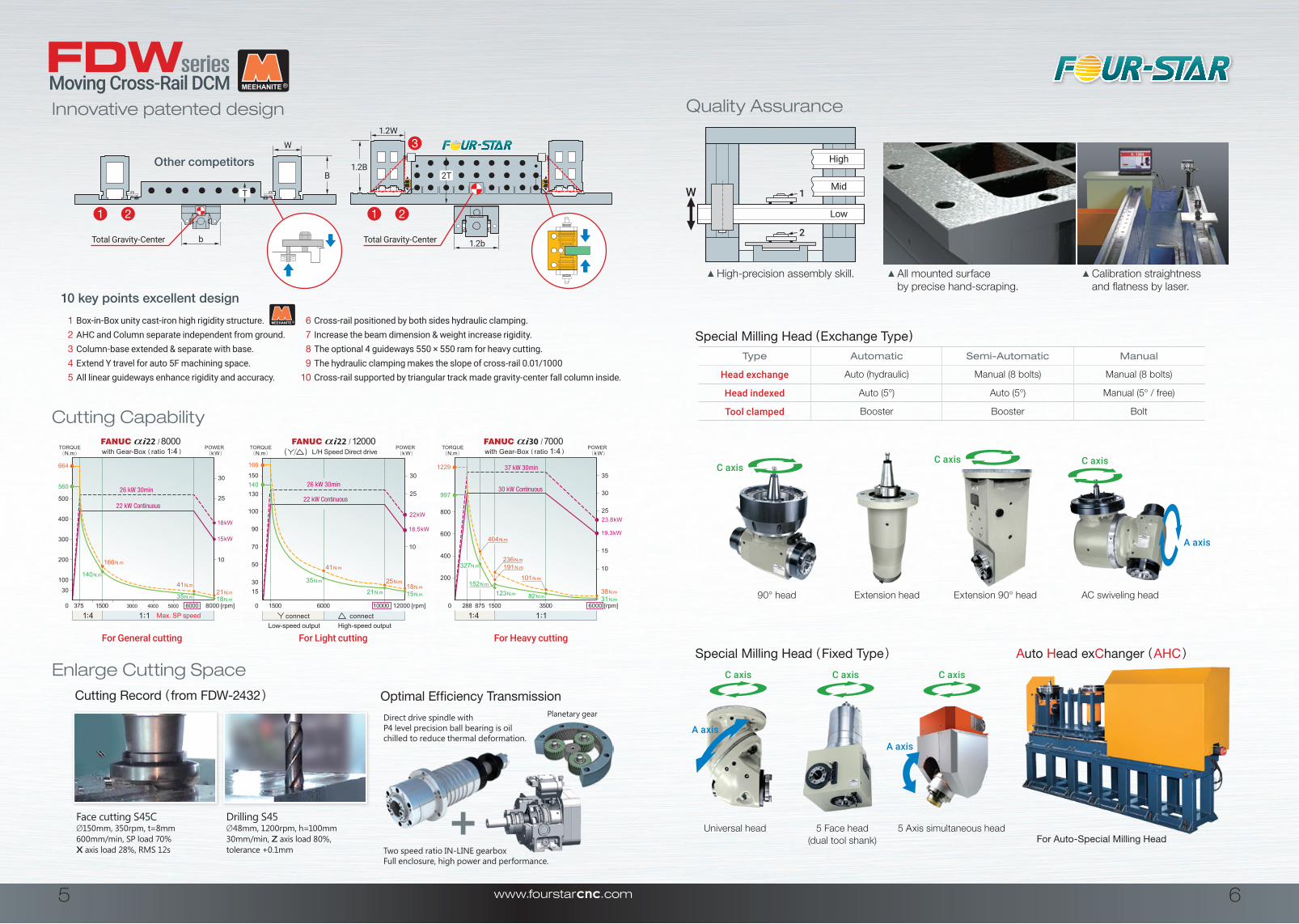
Direct drive spindle withP4 level precision ball bearing is oilchilled to reduce thermal deformation.
Two speed ratio IN-LINE gearbox Full enclosure, high power and performance.
Planetary gear
1
2
W
Low
Mid
High
C axis
A axis
A axis
C axis
A axis
C axisC axis
C axis
C axis
T
2TB1.2B
W
1.2W
1.2bb
( k W )POWER
( N.m )TORQUE
with Gear-Box ( ratio 1: 4 )
i22 8000/
1: 4 1
: 1
37 kW 30min
30 kW Continuous
( k W )POWER
( N.m )TORQUE
with Gear-Box ( ratio 1: 4 )
i30 7000/
1: 4 1
: 1
( k W )POWER
( N.m )TORQUE
i22 12000/
connectconnect
21 N.m18 N.m
166 N.m
140 N.m
41 N.m
35 N.m
500 25
30
664
560
15003750 8000 [rpm]
18 kW
15 kW
60003000 4000 5000
400
300
200
100
30
10
38 N.m31 N.m
25
30
23.8 kW
19.3 kW
10
35
8750 6000 [rpm]35001500
200
997
400
600
800
1229
101 N.m
82 N.m
236 N.m191 N.m
152 N.m
123 N.m
404 N.m
327N.m
22 kW
18.5 kW90
166
140
15000 12000 [rpm]100006000
100
50
70
1530
130
150
25
30
10
18 N.m15 N.m21 N.m
25 N.m
41 N.m
35 N.m
High-speed outputLow-speed output
L/H Speed Direct drive
26 kW 30min
22 kW Continuous26 kW 30min
22 kW Continuous
288
15
Max. SP speed
( )
For General cutting For Light cutting For Heavy cutting
Type Automatic Semi-Automatic Manual
Head exchange Auto (hydraulic) Manual (8 bolts) Manual (8 bolts)
Head indexed Auto (5°) Auto (5°) Manual (5° / free)
Tool clamped Booster Booster Bolt
Quality Assurance
All mounted surface by precise hand-scraping.
Calibration straightness and flatness by laser.
Cutting Capability
Cutting Record ( from FDW-2432 )
Face cutting S45CØ150mm, 350rpm, t=8mm600mm/min, SP load 70% X axis load 28%, RMS 12s
Drilling S45Ø48mm, 1200rpm, h=100mm30mm/min, Z axis load 80%,tolerance +0.1mm
Optimal Efficiency Transmission
Enlarge Cutting Space
1 Box-in-Box unity cast-iron high rigidity structure. 6 Cross-rail positioned by both sides hydraulic clamping.2 AHC and Column separate independent from ground. 7 Increase the beam dimension & weight increase rigidity.3 Column-base extended & separate with base. 8 The optional 4 guideways 550 × 550 ram for heavy cutting.4 Extend Y travel for auto 5F machining space. 9 The hydraulic clamping makes the slope of cross-rail 0.01/10005 All linear guideways enhance rigidity and accuracy. 10 Cross-rail supported by triangular track made gravity-center fall column inside.
10 key points excellent design
For Auto-Special Milling Head
Special Milling Head ( Exchange Type )
Special Milling Head ( Fixed Type ) Auto Head exChanger ( AHC )
90° head Extension head Extension 90° head AC swiveling head
Universal head 5 Face head 5 Axis simultaneous head(dual tool shank)
Innovative patented design
Other competitors
High-precision assembly skill.
Moving Cross-Rail DCM
Total Gravity-Center Total Gravity-Center
1 2 1 2
3
7 8
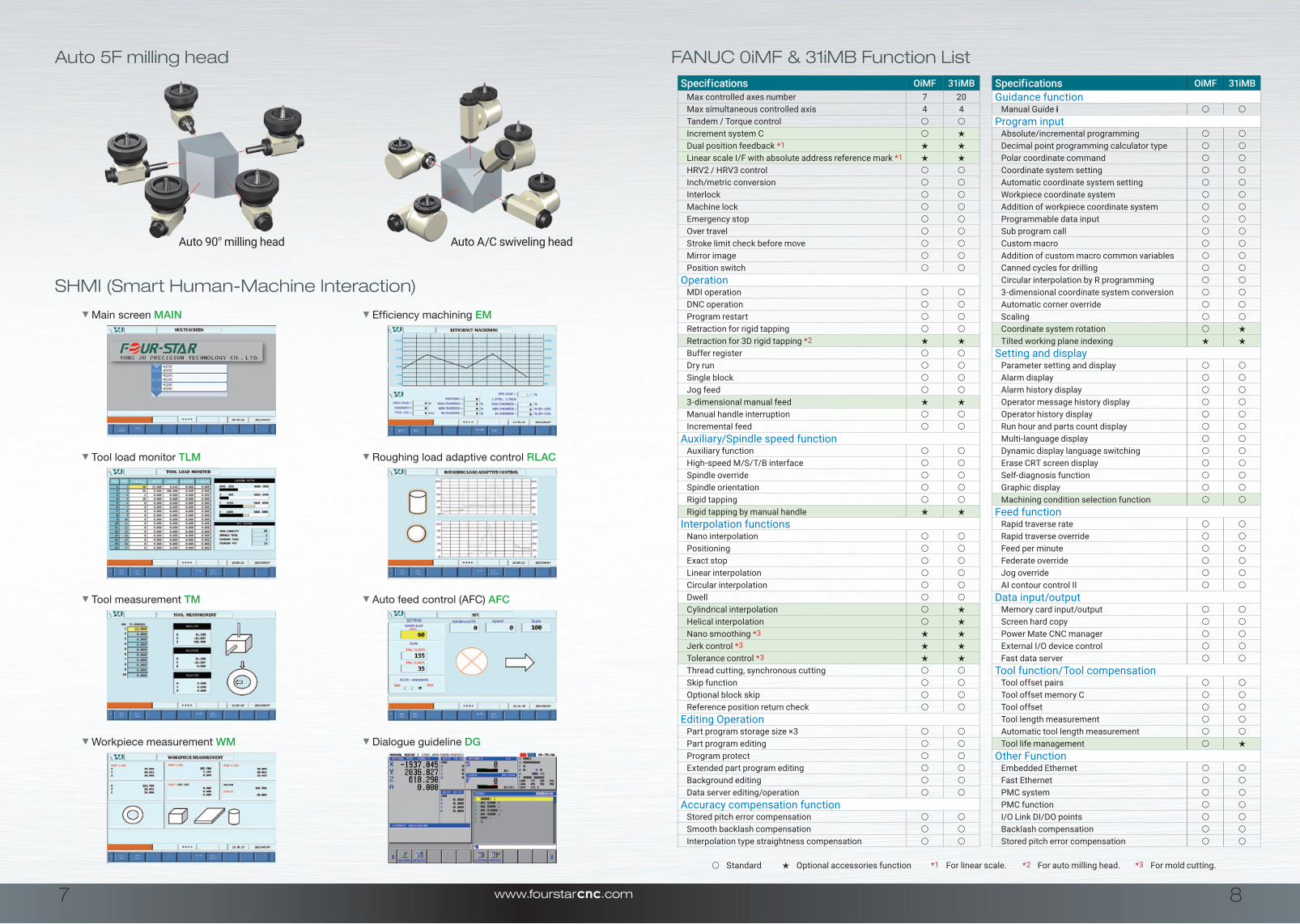
Specifications OiMF 31iMBMax controlled axes number 7 20Max simultaneous controlled axis 4 4Tandem / Torque control ○ ○Increment system C ○ ★Dual position feedback *1 ★ ★Linear scale I/F with absolute address reference mark *1 ★ ★HRV2 / HRV3 control ○ ○Inch/metric conversion ○ ○Interlock ○ ○Machine lock ○ ○Emergency stop ○ ○Over travel ○ ○Stroke limit check before move ○ ○Mirror image ○ ○Position switch ○ ○
Operation MDI operation ○ ○DNC operation ○ ○Program restart ○ ○Retraction for rigid tapping ○ ○Retraction for 3D rigid tapping *2 ★ ★Buffer register ○ ○Dry run ○ ○Single block ○ ○Jog feed ○ ○3-dimensional manual feed ★ ★Manual handle interruption ○ ○Incremental feed ○ ○
Auxiliary/Spindle speed functionAuxiliary function ○ ○High-speed M/S/T/B interface ○ ○Spindle override ○ ○Spindle orientation ○ ○Rigid tapping ○ ○Rigid tapping by manual handle ★ ★
Interpolation functionsNano interpolation ○ ○Positioning ○ ○Exact stop ○ ○Linear interpolation ○ ○Circular interpolation ○ ○Dwell ○ ○Cylindrical interpolation ○ ★Helical interpolation ○ ★Nano smoothing *3 ★ ★Jerk control *3 ★ ★Tolerance control *3 ★ ★Thread cutting, synchronous cutting ○ ○Skip function ○ ○Optional block skip ○ ○Reference position return check ○ ○
Editing OperationPart program storage size ×3 ○ ○Part program editing ○ ○Program protect ○ ○Extended part program editing ○ ○Background editing ○ ○Data server editing/operation ○ ○
Accuracy compensation functionStored pitch error compensation ○ ○Smooth backlash compensation ○ ○Interpolation type straightness compensation ○ ○
Specifications OiMF 31iMBGuidance function
Manual Guide i ○ ○Program input
Absolute/incremental programming ○ ○Decimal point programming calculator type ○ ○Polar coordinate command ○ ○Coordinate system setting ○ ○Automatic coordinate system setting ○ ○Workpiece coordinate system ○ ○Addition of workpiece coordinate system ○ ○Programmable data input ○ ○Sub program call ○ ○Custom macro ○ ○Addition of custom macro common variables ○ ○Canned cycles for drilling ○ ○Circular interpolation by R programming ○ ○3-dimensional coordinate system conversion ○ ○Automatic corner override ○ ○Scaling ○ ○Coordinate system rotation ○ ★Tilted working plane indexing ★ ★
Setting and displayParameter setting and display ○ ○Alarm display ○ ○Alarm history display ○ ○Operator message history display ○ ○Operator history display ○ ○Run hour and parts count display ○ ○Multi-language display ○ ○Dynamic display language switching ○ ○Erase CRT screen display ○ ○Self-diagnosis function ○ ○Graphic display ○ ○Machining condition selection function ○ ○
Feed functionRapid traverse rate ○ ○Rapid traverse override ○ ○Feed per minute ○ ○Federate override ○ ○Jog override ○ ○AI contour control II ○ ○
Data input/outputMemory card input/output ○ ○Screen hard copy ○ ○Power Mate CNC manager ○ ○External I/O device control ○ ○Fast data server ○ ○
Tool function/Tool compensationTool offset pairs ○ ○Tool offset memory C ○ ○Tool offset ○ ○Tool length measurement ○ ○Automatic tool length measurement ○ ○Tool life management ○ ★
Other FunctionEmbedded Ethernet ○ ○Fast Ethernet ○ ○PMC system ○ ○PMC function ○ ○I/O Link DI/DO points ○ ○Backlash compensation ○ ○Stored pitch error compensation ○ ○
○ Standard ★ Optional accessories function *1 For linear scale. *2 For auto milling head. *3 For mold cutting.
Auto 90o milling head Auto A/C swiveling head
Tool load monitor TLM Roughing load adaptive control RLAC
Main screen MAIN Efficiency machining EM
Tool measurement TM Auto feed control (AFC) AFC
FANUC 0iMF & 31iMB Function ListAuto 5F milling head
Workpiece measurement WM Dialogue guideline DG
SHMI (Smart Human-Machine Interaction)

9 10
W L
H
ATC AHC
Standard Accessories Optional Accessories1. FANUC 0 i MF + 10.4” LCD 1. X travel 7m / 8m / 9m / 10m
2. Spindle cooler 2. Mitsubishi / Siemens / Heidenhain Controller
3. Spindle air blast 3. High speed Spindle ( 8000~20000rpm )
4. N2 Counter balancing system 4. Coolant Through Spindle ( CTS )
5. Dual stage H/L planetary gearbox 5. 90° milling head ( Auto, Semi-auto, Manual )
6. Independent auto lubrication system 6. Extend milling head ( Auto, Semi-auto, Manual )
7. Program end alarm lamp 7. AC swiveling milling head ( Auto, Manual )
8. Rigid tapping 8. AHC system ( for auto milling head )
9. Electric cabinet heat exchanger 9. Toggle head stand ( for semi-auto / Manual milling head )
10. USB / RS232 / Ethernet interface 10. Five face milling head ( Fixed type )
11. Coolant system 11. Universal milling head ( Fixed type, Manual )
12. Dual spiral type chip remover 12. 5 axis simultaneous milling head
13. Metal belt chip conveyor with cart 13. Y travel extend 650mm ( for Auto 5F machining )
14. Chain type ATC 32pcs 14. Transformer
15. Semi-enclosure splash guard ( FDW-18/21/24 ) 15. X, Y, Z axis linear scale
16. Open type splash guard ( FDW-28/32/36/42 ) 16. Tool length measurement
17. ATC auto door 17. Auto work piece measurement
18. Foot switch for tool away 18. CNC rotary table ( indexed / simultaneous )
19. Working lamp 19. Coolant thru tool holder device
20. Leveling screw + foundation bolts 20. Full enclosure splash guard
21. Tool kit & Operator’s manual 21. Oil skimmer
22. Air / water cleaning equipment 22. Spindle power 30 / 37 kW with gearbox
23. W axis linear scale ( 2 pcs ) 23. Heavy duty RAM 550 x 550 ( FDW-28 and up )
Item Unit FDW-18 FDW-21 FDW-24
Model FDW- 1822 1832 1842 1852 2122 2132 2142 2152 2432 2442 2452
Distance between columns mm 1850 2150 2450
Table sizeLength mm 2000 3000 4000 5000 2000 3000 4000 5000 3000 4000 5000
Width mm 1500 1800 2000
Maximum Table Load ton 12 15 18 20 12 15 18 20 15 18 20
T slot Width× Pitch×No. mm 22 × 150 × 9 22 × 150 × 11 22 × 150 × 13
Travel
X -axis mm 2200 3200 4200 5200 2200 3200 4200 5200 3200 4200 5000
Y -axis mm 1800 2100 2400
Z -axis mm 800 (1100)
W -axis mm 1000 ( opt. 1500)
Spindle
Nose to table mm 120~1920
Ram Size mm □ 450 × 400
Taper / Power / Speed rpm / kW BBT50 - 22/26kW - 6000rpm with 2 stage gearbox
Feedrate
Cutting m / min 12
X axis m / min 15 15 12 10 15 15 12 10 15 12 10
Y / Z / W axis m / min 15 / 15 / 5
Accuracy mm Positioning ±0.015/full travel ; Positioning ±0.015/full travel ±0.003 ; Slope of cross-rail 0.01/1000
Toolmagazine
Capcity / Dia mm 32 tools , max. dia Ø125(Full tool) / Ø220(Adjacent empty)
Max.Length / Weight mm / Kg 400 mm / 20 kg
Tool selection Random shortest direction / M24 P3.0 - 45°
Machine size
Length m 7.2 9.2 11.2 13.2 7.2 9.2 11.2 13.2 9.2 11.2 13.2
Width m 5.1 5.4 5.7
Height m 5.1 (6.0)
Machine Weight ( ±10% ) ton 40 44 48 52 42 46 50 54 48 53 58
FDW-28 FDW-32 FDW-36 FDW-42
2832 2842 2852 2860 3232 3242 3252 3260 3642 3652 3660 4242 4252 4260
2850 3250 3650 4250
3000 4000 5000 6000 3000 4000 5000 6000 4000 5000 6000 4000 5000 6000
2200 2600 3000
18 20 22 24 18 20 22 24 22 24 26 22 24 26
28 × 180 × 13 28 × 200 × 13 28 × 200 × 15
3200 4200 5200 6000 3200 4200 5200 6000 4200 5200 6000 4200 5200 6000
2800 3200 3600 4200
1100
1000 (opt. 1500 / 2000)
145~2245
□ 450 × 400 (opt. 550 × 550)
BBT50 - 22/26kW - 6000rpm with 2 stage gearbox
10
15 12 10 10 15 12 10 10 12 10 10 12 10 10
12 / 12 / 3
Positioning ±0.015/full travel ; Positioning ±0.015/full travel ±0.003 ; Slope of cross-rail 0.01/1000
32 tools , max. dia Ø125(Full tool) / Ø220(Adjacent empty)
400 mm / 20 kg
Random shortest direction / M24 P3.0 - 45°
9.2 11.2 13.2 15.0 9.2 11.2 13.2 15.0 11.2 13.2 15.0 11.2 13.2 15.0
6.0 6.4 6.8 7.4
5.9
55 60 65 70 58 63 68 73 67 72 77 72 76 80
All data will change based on the actual situation without notice.
Series Specification list
Machine Layout & Dimension