mower engine trouble shooting - msu librariesarchive.lib.msu.edu/tic/wetrt/article/1978apr18.pdf ·...
TRANSCRIPT

MOWER ENGINE TROUBLE SHOOTING
When you pull out a trim mower in the spring and it won't start, temptation is just to replace it with a new one. Very often, a few hours labor on a rainy day and a few dollars worth of parts can give you another season from that mower. Weigh the costs of repair against the cost of replacement. WEEDS TREES & TURF went to Morris Mower and Small Engine Repair to find out what the typical causes of small engine failure are. Clint Morris, who runs the shop, has been repairing small engines for 20 years. He attends all the manufacturers' schools to keep abreast of small engine technology. "If a small engine has been properly taken care of, oil changed, filter cleaned, blade sharpened, and the mechanical parts are sound, getting it to run properly is simply a matter of getting the spark and fuel to meet in the right place at the right time," according to Morris.
If an engine is otherwise mechanically sound, test for spark by holding the spark plug wire close to, but not touching, the spark plug. Pull the starter rope. Blue sparks should arc between the wire and tne plug.
If there is no spark, it is necessary to replace the points and condenser and time the engine. First step is to loosen the bolt holding the air filter and remove it.
Remove engine housing in place. Grasp the hous-ing by the top ana lift sharply.
There are special tools to remove the starter clutch, but in lieu of these, a soft wooden block and hammer will do. The clutch loosens in a counter-clockwise manner, so place the block against one of the ears of the clutch and hit the block with a hammer until the clutch is free. It should then spin off.
Guarding the threads on the crankshaft, place a screwdriver under the edge of the flywheel and press down. Tap the top of the crankshaft with the hammer and the flywheel will break loose. There is a cup-ped spring washer under the flywheel.
Two small bolts hold the dust cover over the points and condenser. Remove the cover to expose the points.
The points in this photo have a white, pit-ted surface, indicating they need to be replaced.
Remove the bolt holding the clamp in place over the condenser. There is a small plastic tool provided in new point and condenser kits to aid in removing the wires from the condenser. Place the piece over the spring of the condenser and com-press it until the wires pull free. Install the new condenser by compressing the spring until the wires enter the nole. Reinstall clamp and tighten.

This places the proper tension on the choke valve spring. Replace the linkage in its shaft ana replace the cover to hold it in place. Tighten the carburetor to the gas tank. Attach^ the tank-carburetor assem-bly to the engine, tilting it to attach the governor linkage before securing it. At-tach the governor spring and the control cable.
The control plate must come into contact with the point indicated by the pliers in order to stop it. Raise it up if necessary. Refill the tank at least half full. Start with the air filter off, but replace it after the engine starts and before making any adjustments. Adjust the idle mixture until the engine is running smoothly.
Reinstall the dust cover and tighten it. Place the spring washer back over the crankshaft with the cup up. Line up the grooves in the crankshaft and flywheel so tnat the aluminum key will slip in without force. Always use an aluminum key in this slot. If the key is bent or damaged, it will affect the timing of the engine.
Remove the bolt holding the point assem-bly and remove the points, with spring at-tached. Install the new points in tne same manner. In order to gap the points cor-rectly at .020, it is necessary to rotate the engine so that the slot in tne crank shaft points towards the rear of the engine (away from the cylinder head).
The engine is timed by adjusting the air gap between the legs of the magneto and tne magnetic surface of the flywheel. A postcard is just the right thickness for this. Loosen the two screws holding the magneto and move it for the right gap. Replace the starter clutch and tap it with the wooden block and hammer in a clock-wise manner until it is secure. Replace the trash screen. Clean the air filter ele-ment in kerosene or hot soapy water. Saturate it with oil and squeeze out the excess.
Fill the gas tank half full and attempt to start it. Screw in the idle mixture screw (clockwsie) until snug. Back it off one and one-half turns. Unless something is wrong with the carburation, the engine should start. If it starts but fails to res-pond to the idle mixture screw, this in-dicates warping between the faces of the carburetor and gas tank. Briggs & Stratton Kepair Kit#391413 will correct this.
Place the pin from the repair kit in the hole as indicated and place the small teflon washer over the pin.
Place a 5/16-inch bolt behind the choke valve as shown.
Insert a feeler gauge between the points and adjust the gap by loosening the con-denser and moving it. There should be only minimum resistance as the gauge is pulled through the points.
Remove the control cable from the engine housing. Lift it up and slide it out of the hole in the carburetor control plate. Remove the screw in the back and the side. Make sure you don't lose the spacer behind the side screw. Remove the spring from the control plate, being careful not to stretch it. Lift the tank and tilt it to remove the governor linkage wire.
Remove the choke linkage cover and slip the linkage free of shaft.
Remove the bolts holding the carburetor to the gas tank and lift the carburetor free.
F V
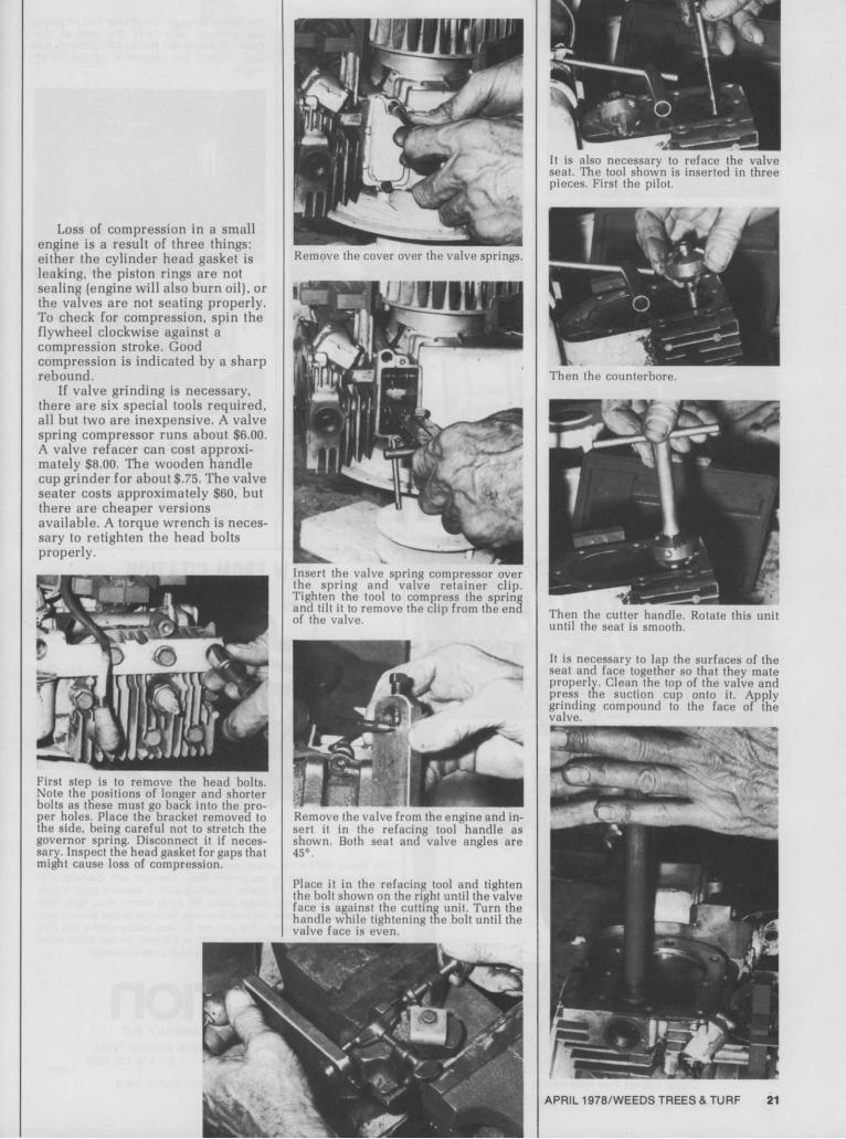
Loss of compression in a small engine is a result of three things: either the cylinder head gasket is leaking, the piston rings are not sealing (engine will also burn oil), or the valves are not seating properly. To check for compression, spin the flywheel clockwise against a compression stroke. Good compression is indicated by a sharp rebound.
If valve grinding is necessary, there are six special tools required, all but two are inexpensive. A valve spring compressor runs about $6.00. A valve refacer can cost approxi-mately $8.00. The wooden handle cup grinder for about $.75. The valve seater costs approximately $60, but there are cheaper versions available. A torque wrench is neces-sary to retighten the head bolts properly.
First step is to remove the head bolts. Note the positions of longer and shorter bolts as these must go back into the pro-per holes. Place the bracket removed to the side, being careful not to stretch the governor spring. Disconnect it if neces-sary. Inspect the head gasket for gaps that might cause loss of compression.
Remove the cover over the valve springs.
Insert the valve spring compressor over the spring and valve retainer clip. Tighten the tool to compress the spring and tilt it to remove the clip from the ena of the valve.
Remove the valve from the engine and in-sert it in the refacing tool handle as shown. Both seat and valve angles are 45°.
Place it in the refacing tool and tighten the bolt shown on the right until the valve face is against the cutting unit. Turn the handle wnile tightening tne bolt until the valve face is even.
It is also necessary to reface the valve seat. The tool shown is inserted in three pieces. First the pilot.
Then the counterbore.
Then the cutter handle. Rotate this unit until the seat is smooth.
It is necessary to lap the surfaces of the seat and face together so that they mate properly. Clean the top of the valve and press the suction cup onto it. Apply grinding compound to the face of the valve.

valve and tappet. Insert the valve into the engine and check with a feeler gauge for .005-.007 for the intake (smaller) valve and .009-.Oil for the exhaust. Grind only a minimum at one time until the proper gap is reached.
Replace the valve by inserting the com-pressed spring into the engine and sliding
the valve through the spring and slipping the retainer clip over the end of the valve. Release the spring and remove the tool. Repeat the sequence for the other valve.
Install a new head gasket and replace the head with the proper bolts in the right holes. Tighten the bolts finger tight. Be sure and replace the bracket. Tighten the bolts in sequence, a little at a time, until the proper torque is reached. Tightening one much more than the others will result in a warped head. Proper torque is 140 inch pounds.
Rotate the wooden handle between your hands while pressing down . . .
until there is a smooth ring ground completely around the valve seat
t ace and
If much material was removed, it may be necessary to widen the gap between the
OUR QUALITY IS SHOWING
Ask for our NEW
free Catalog
SAFETY TEST INC. PO. Drawer 400 Shelby, N. C. 28150 (704) 482 7346
Circle 164 on free information card
WEEDS TREES & TURF/APRIL 1978
NEW FROM CITATION
The Model 6421 is the newest pressure washer to be added to Citation's ever-expanding cleaning equipment line. The unit will discharge 240 GPH at 1000 PSI. It comes complete with a stainless steel triplex pump, 3 HP, 220 volt, single phase, 60 cycle motor, float tank, dual chemical metering valve, 40-foot discharge hose and trigger control gun. Portable gear is optional! The unit can be used independently as a cold water washer or in combination with a Citation Model 6400 series continuous water heater to make a hot high pressure washer.
citation MANUFACTURING COMPANY, INC.
P. 0 . Box 550 - Siloam Springs, Arkansas 72761 Phone: (501)524-6471 TWX 910-720-7267
C-164K