mp5s/mp5y/mp5w/mp5m series - autonics - hemfile/mp5s_mp5m_en_cat_150805.pdf · m-6...
TRANSCRIPT
M-6
MP5S/MP5Y/MP5W/MP5M Series
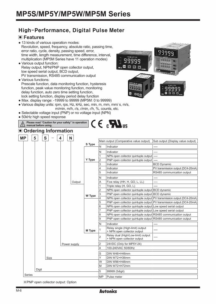
※PNP open collector output: Option
FeaturesHigh-Performance, Digital Pulse Meter
13 kinds of various operation modes:Revolution, speed, frequency, absolute ratio, passing time,error ratio, cycle, density, passing speed, error,time width, length measurement, time difference, interval,multiplication (MP5M Series have 11 operation modes)
Various output function:Relay output, NPN/PNP open collector output,low speed serial output, BCD output,PV transmission, RS485 communication output
Various functions:Prescale function, data monitoring function, hysteresisfunction, peak value monitoring function, monitoringdelay function, auto zero time setting function,lock setting function, display period delay function
Max. display range: -19999 to 99999 (MP5M: 0 to 99999) Various display units: rpm, rps, Hz, kHz, sec, min, m, mm, mm/ s, m/s,
m/min, m/h, ℓ/s, ℓ/min, ℓ/h, %, counts, etc. Selectable voltage input (PNP) or no voltage input (NPN) 50kHz high speed response
Ordering Information
Series
Digit
Size
Power supply
Output
M Type
W Type
Y Type
S Type
MP 5 S 4 NMain output (Comparative value output) Sub output (Display value output)
N Indicator -
N Indicator -1 NPN open collector quintuple output -2 PNP open collector quintuple output -3 Indicator BCD Dynamic4 Indicator PV transmission output (DC4-20mA)5 Indicator RS485 communication output
N Indicator -A Five relay (HH, H, GO, L, LL) -1 Triple relay (H, GO, L) -2 NPN open collector quintuple output BCD dynamic3 PNP open collector quintuple output BCD dynamic4 NPN open collector quintuple output PV transmission output (DC4-20mA)5 PNP open collector quintuple output PV transmission output (DC4-20mA)6 NPN open collector quintuple output Low speed serial output7 PNP open collector quintuple output Low speed serial output8 NPN open collector quintuple output RS485 communication output9 PNP open collector quintuple output RS485 communication output
N Indicator -
1 Relay single (High-limit) output+ NPN open collector output -
2 Relay dual (High/Low-limit) output+ NPN open collector output -
2 24VDC (Only for MP5Y-24)4 100-240VAC 50/60Hz
S DIN W48×H48mmY DIN W72×H36mmW DIN W96×H48mmM DIN W72×H72mm
5 99999 (5digit)
MP Pulse meter
Please read “Caution for your safety” in operation manual before using.
M-7
Pulse(Rate) Meter
(A) Photoelectric Sensors
(B) FiberOpticSensors
(C) Door/AreaSensors
(D) ProximitySensors
(E) PressureSensors
(F) RotaryEncoders
(G) Connectors/Sockets
(H)TemperatureControllers
(I)SSRs / PowerControllers
(J) Counters
(K) Timers
(L) PanelMeters
(M)Tacho /Speed / PulseMeters
(N)DisplayUnits
(O)SensorControllers
(P)SwitchingMode PowerSupplies
(Q)Stepper Motors & Drivers & Controllers
(R)Graphic/LogicPanels
(S)FieldNetworkDevices
(T) Software
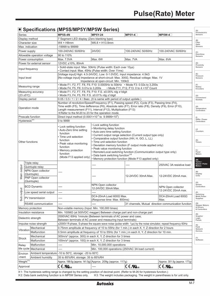
※1: The hysteresis setting range is changed by the setting position of decimal point. (Refer to M-26 for hysteresis function.)※2: Data bank switching function is in MP5W Series only. ※3: The weight includes packaging. The weight in parentheses is for unit only.
Specifications (MP5S/MP5Y/MP5W Series)Series MP5S-4N MP5Y-24 MP5Y-4 MP5W-4 Display method 7 Segment LED display (Zero blanking type)Character size W4 × H8mm W6.8 × H13.8mmMax. indication -19999 to 99999Power supply 100-240VAC 50/60Hz 24VDC 100-240VAC 50/60Hz 100-240VAC 50/60HzAllowable operation voltage 90 to 110%Power consumption Max. 7.5VA Max. 6W Max. 7VA Max. 6VAPower for external sensor 12VDC ±10%, 80mA
Input frequency • Soild-state input: Max. 50kHz (Pulse width: Each over 10) • Contact input: Max. 45Hz (Pulse width: Over 11ms)
Input level[Voltage input] High: 4.5-24VDC, Low: 0-1.0VDC, Input impedance: 4.5kΩ[No-voltage input] Impedance at short-circuit: Max. 300Ω, Residual voltage: Max. 1V
Impedance at open-circuit: Min. 100kΩ
Measuring range • Mode F1, F2, F7, F8, F9, F10: 0.0005Hz to 50kHz • Mode F3: 0.02s to 3,200s• Mode F4, F5, F6: 0.01s to 3,200s • Mode F11, F12, F13: 0 to 4 ×10⁹ Count
Measuring accuracy(23 ±5)
• Mode F1, F2, F7, F8, F9, F10: F.S. ±0.05% rdg ±1digit• Mode F3, F4, F5, F6: F.S. ±0.01% rdg ±1digit
Display period 0.05 / 0.5 / 1 / 2 / 4 / 8sec. (It is same with period of output update.)
Operation mode
Number of revolution/Speed/Frequency (F1), Passing speed (F2), Cycle (F3), Passing time (F4),Time width (F5), Time defference (F6), Absolute ratio (F7), Error ratio (F8), Density (F9), Error (F10),Length measurement (F11), Interval (F12), Multiplication (F13)※Refer to the M-20 to 23 for the operation mode.
Prescale function Direct input method (0.0001×10⁻⁹ to 9.9999×10⁹) Hysteresis※1 0 to 9999
Other functions
• Lock setting function• Auto-Zero time setting
function• Time unit selection
function• Peak value monitoring
function• Memory protection
function(Mode F13 applied only)
• Lock setting function• Monitoring delay function• Auto-zero time setting function• Current output range selection (Current output type only) • Comparative output function (HH, H, GO, L, LL)• Time unit selection function• Deviation memory function (F output mode applied only)• Peak value monitoring function• Remote/Local switching function (Communication output type only)• Data bank switching function※2
• Memory protection function (Mode F13 applied only)
Mai
n ou
tput
Triple relay
-
- - 250VAC 3A resistive load Quintuple relayNPN Open collector (Quintuple) - 12-24VDC 30mA Max. 12-24VDC 20mA max.PNP Open collector (Quintuple)
Sub
out
put BCD Dynamic - NPN Open collector
12-24VDC 30mA Max. NPN Open collector12-24VDC 20mA max.
Low speed serial output - -
PV transmission - DC4-20mA Load 600Ω Max.(Response time: Max. 800ms)
DC4-20mA Load 600Ω Max.
RS485 communication - - 31 channels, Mutual direction communication functionMemory protection Non-volatile memory (Input: Min. 100,000 times)Insulation resistance Min. 100MΩ (at 500VDC megger) Between charge part and non-charge part
Dielectric strength 2000VAC 60Hz 1minute (Between terminals of AC power and case,Between terminals of AC power and measuring input terminals)
Impulse noise strength ±2000V R-phase, S-phase the square wave noise (pulse width: 1) by the noise simulator, repeat frequency 60Hz
VibrationMechanical 0.75mm amplitude at frequency of 10 to 55Hz (for 1 min.) in each X, Y, Z direction for 2 hoursMalfunction 0.5mm amplitude at frequency of 10 to 55Hz (for 1 min.) in each X, Y, Z direction for 10 min.
ShockMechanical 300m/s² (approx. 30G) in each X, Y, Z direction for 3 timesMalfunction 100m/s² (approx. 10G) in each X, Y, Z direction for 3 times
Relay life cycle
Malfunction - Min. 10,000,000 operationsMechanical - Min. 100,000 operations (250VAC 3A load current)
Environ-ment
Ambient temperature -10 to 50, storage: -20 to 60Ambient humidity 35 to 85%RH, storage: 35 to 85%RH
Weight※3 Approx. 199.5g (approx. 141.5g) Approx. 209g (approx. 117g) Approx. 301.5g (approx. 177g)
Approval -

M-8
MP5S/MP5Y/MP5W/MP5M Series
HOLD/RESET
HOLD/RESET
HOLD/RESET
Black Black BlackBlack Black BlackBrown Brown BrownBlue Blue Blue
INA INA INA
H L
INB INB INB+12V +12V +12V0V 0V 0V
SOURCE SOURCE SOURCE
High High Low
100-240VAC50/60Hz
100-240VAC50/60Hz
100-240VAC50/60Hz
CONTACT OUT:250VAC 3A RESISTIVE LOAD
CONTACT OUT:250VAC 3A RESISTIVE LOAD
15 15 15
8 8 8
1 1 1
9 9 9
2 2 2
10 10 10
3 3 3
11 11 11
4 4 4
12 12 12
5 5 5
13 13 13
6 6 6
14 14 14
7 7 7
16 16 16
17 17 17
18 18 18
※MP5S, MP5Y, MP5W have same function. ※Environment resistance is rated at no freezing or condensation.
Connections
Specifications (MP5M Series)Model
MP5M-4N MP5M-41 MP5M-42Indicator High-limit setting type High/Low-limit setting type
Display method 7 Segment LED display (Zero blanking), Character size: W4 X H8mmMax. indication 0.0001 to 99999Power supply 100-240VAC 50/60HzAllowable operation voltage 90 to 110%Power consumption Approx. 7.5VA (240VAC) Approx. 8VA (240VAC)Power for external sensor 12VDC ±10%, 80mA
Input frequency • Solid-state input: Max. 50kHz (pulse width: over 10)• Contact input: Max. 45Hz (pulse width:over 11ms)
Input level[Voltage input] High: 4.5-24VDC, Low: 0-1.0VDC, Input impedance: 4.5kΩ[No-voltage input] Impedance at short-circuit: Max. 300Ω, Residual voltage: Max. 1V Impedance at open-circuit: Min. 100kΩ
Measuring range • Mode F1, F2, F7, F8: 0.0005Hz to 50kHz • Mode F3: 0.02s to 3,200s• Mode F4, F5, F6: 0.01s to 3,200s • Mode F9, F10, F11: 0 to 4 ×10⁹ Count
Measuring accuracy (23 ±5) • Mode F1, F2, F7, F8: F.S. ±0.05% rdg ±1digit • Mode F3, F4, F5, F6: F.S. ±0.01% rdg ±1digitDisplay period 0.05 / 0.5 / 1 / 2 / 4 / 8sec. (It is same with period of output update.)
Operation modeNumber of revolution/Speed/Frequency (F1), Passing speed (F2), Cycle (F3), Passing time (F4),Time width (F5), Time difference (F6), Absolute ratio (F7), Density (F8), Length measurement (F9),Interval (F10), Multiplication (F11) ※Refer to M-20 to 23 for operation mode.
Prescale function Direct input method (0.0001×10⁻⁹ to 9.9999×10⁹) Hysteresis - 0 to 9999
Other function
• Lock setting function• Auto-Zero time setting function• Time unit selection function• Peak value monitoring function• Memory protection function(Mode F11 applied only)
• Lock setting function• Monitoring delay function• Auto-Zero time setting function• Time unit selection function• Peak value monitoring function• Memory protection function(Mode F11 applied only)
• High-limit output function (H)
• Lock setting function• Monitoring delay function• Auto-Zero time setting function• Time unit selection function• Peak value monitoring function• Memory protection function (Mode F11 applied only)• Comparative output function (H, L)• Output mode selection function(S, H, L, B, I, F)
• Deviation memory function (F output mode applied only)
Mainoutput
Relay-
250VAC 3A resistive load 1c 250VAC 3A resistive load 1a×2NPN Open Collector 30VDC 100mA Max. 30VDC 100mA Max. ×2
Memory protection Non-volatile memory (Input: Min. 100,000 operations)Approval Unit weight Approx. 275g Approx. 310g Approx. 330g
MP5M Series MP5M-4N (Indicator) MP5M-41 (High-limit setting type) MP5M-42 (High/Low-limit setting type)
M-9
Pulse(Rate) Meter
(A) Photoelectric Sensors
(B) FiberOpticSensors
(C) Door/AreaSensors
(D) ProximitySensors
(E) PressureSensors
(F) RotaryEncoders
(G) Connectors/Sockets
(H)TemperatureControllers
(I)SSRs / PowerControllers
(J) Counters
(K) Timers
(L) PanelMeters
(M)Tacho /Speed / PulseMeters
(N)DisplayUnits
(O)SensorControllers
(P)SwitchingMode PowerSupplies
(Q)Stepper Motors & Drivers & Controllers
(R)Graphic/LogicPanels
(S)FieldNetworkDevices
(T) Software
RESET/HOLD※1
HOLD/RESET ※1
HOLD/RESET ※1
INA
INA INA
INB
INB INB
+12V
+12V +12V
0V
0V 0V
SOURCE
SOURCE SOURCE+ +- -
100-240VAC 50/60Hz
100-240VAC 50/60Hz24VDC
100-240VAC 50/60Hz24VDC
8
1
1
1
1
1
1
1
12
2
2
2
2
2
23
3
3
3
3
3
34
4
4
4
4
4
45
5
5
5
5
5
56
6
6
6
6
6
67
7
7
7
7
7
8
8
8
8
8
9
9
9
9
9
10
10
10
10
10
7
9
2
10
3 4 5
6 7
PCB② ④ ⑥ ⑧ ⑩
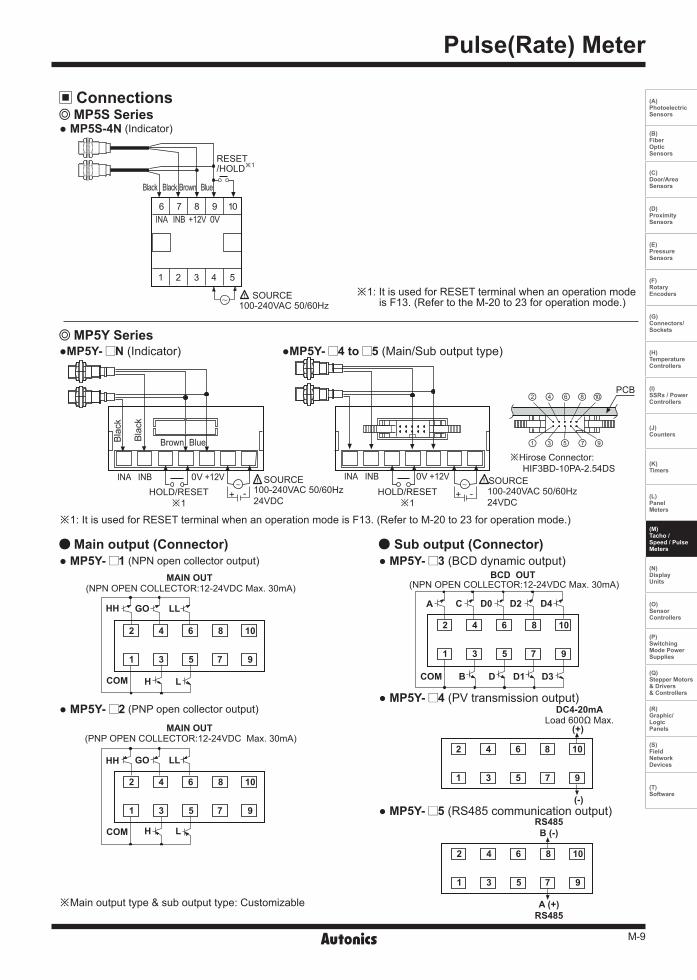
① ③ ⑤ ⑦ ⑨※Hirose Connector: HIF3BD-10PA-2.54DS
※1: It is used for RESET terminal when an operation mode is F13. (Refer to M-20 to 23 for operation mode.)
HH
HH
AGO
GO
C
(-)
RS485B (-)
A (+)RS485
(+)
LL
LL
D0 D2 D4
L
L
H
H
B D D1 D3COM
COM
COM
MAIN OUT BCD OUT
DC4-20mALoad 600Ω Max.
MAIN OUT
(NPN OPEN COLLECTOR:12-24VDC Max. 30mA) (NPN OPEN COLLECTOR:12-24VDC Max. 30mA)
(PNP OPEN COLLECTOR:12-24VDC Max. 30mA)
※Main output type & sub output type: Customizable
Connections MP5S Series
MP5Y Series
MP5S-4N (Indicator)
MP5Y- N (Indicator)
Main output (Connector) MP5Y- 1 (NPN open collector output)
MP5Y- 2 (PNP open collector output)
MP5Y- 3 (BCD dynamic output)
MP5Y- 4 (PV transmission output)
MP5Y- 5 (RS485 communication output)
Sub output (Connector)
MP5Y- 4 to 5 (Main/Sub output type)
※1: It is used for RESET terminal when an operation mode is F13. (Refer to the M-20 to 23 for operation mode.)
Black Black Brown Blue
Bla
ck
Bla
ck
Brown Blue
M-10
MP5S/MP5Y/MP5W/MP5M Series
2
1
4
3
6
5
8
7
10
9
12
11
14
13
16
15
18
17
20
19
MAIN OUT(NPN open collector
: 12-24VDC Max. 20mA)
COM1
B
D2 ※POLD4D0CAH L 0V
+24VDC30mA Max.HH GO LL
HOLD/RESETINA INB +12V0V0V SOURCE
+ - 100-240VAC 50/60Hz24VDC
CONTACT OUT:250VAC 3A 1aRESISTIVE LOAD
CONTACT OUT:250VAC 3A 1aRESISTIVE LOAD
1
1
1
10HH H
H
GO
GO
L
L
LL COM
10
11 12 13 14 15
11 12 13 14 15
1
2
2
2
2
3
3
3
3
4
4
4
4
5
5
5
5
6
6
6
6
7
7
7
7
8
8
8
8
9
9
9
9
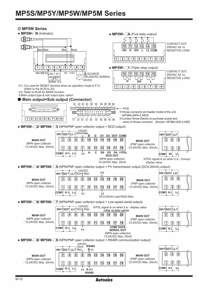
BANK ※2
※1
② ⑫④ ⑭⑥ ⑯⑧ ⑱⑩ ⑳
① ⑪③ ⑬⑤ ⑮⑦ ⑰⑨ ⑲
※1: It is used for RESET terminal when an operation mode is F13. (Refer to the M-20 to 23)
※2: Refer to M-26 for BANK function.※Main output type & sub output type: option
※Hirose connector pin header model of the unit : HIF3BA-20PA-2.54DS※Contact Hirose Electric to purchase socket and wires of Hirose connector. [Socket: HIF3BA-20D-2.54R]
※POL signal is on when it is - (minus) display value
※POL signal is on when it is - display value
PCB
1
2
3
4
5
6MAIN OUT(PNP open collector
:12-24VDC Max. 20mA)
BCD OUT(NPN open collector)
12-24VDC Max. 20mA
SERIAL OUT(NPN open collector)
12-24VDC Max. 20mA
RS485B (-)
A (+)RS485
DC4-20mA Load 600Ω Max.
(+)
(-)
COM2DOTD3D1D
2
1
4
3
6
5
8
7
10
9
12
11
14
13
16
15
18
17
20
19
MAIN OUT(NPN open collector
: 12-24VDC Max. 20mA)
DATACOM2
0V
+24VDC30mA Max.
2
1
4
3
6
5
8
7
10
9
12
11
14
13
16
15
18
17
20
19
MAIN OUT(NPN open collector
: 12-24VDC Max. 20mA)
LATCHCLOCK※POL
0V
0V
+24VDC30mA Max.
2
1
4
3
6
5
8
7
10
9
12
11
14
13
16
15
18
17
20
19
MAIN OUT(NPN open collector
: 12-24VDC Max. 20mA)
COM1
COM1
COM1
H
H
H
L
L
L
COM1 H L
+24VDC30mAMax.HH HH
HH
HH
GO GO
GO
GO
LL LL
LL
LL
HH GO LL
2
2
2
1
1
1
4
4
4
3
3
3
6
6
6
5
5
5
MAIN OUT(PNP open collector
:12-24VDC Max. 20mA)
MAIN OUT(PNP open collector
:12-24VDC Max. 20mA)
MAIN OUT(PNP open collector
:12-24VDC Max. 20mA)
MP5W Series
Main output+Sub output (Connector)
MP5W- N (Indicator)
MP5W- 2/ MP5W- 3 (NPN/PNP open collector output + BCD output)
MP5W- 4/ MP5W- 5 (NPN/PNP open collector output + PV transmission output (DC4-20mA) output)
MP5W- 6/ MP5W- 7 (NPN/PNP open collector output + Low speed serial output)
MP5W- 8/ MP5W- 9 (NPN/PNP open collector output + RS485 communication output)
MP5W- A (Five relay output)
MP5W- 1 (Triple relay output)
Black Black BrownBlue
COM1 H L
HH GO LL
COM1 H L
HH GO LL
COM1 H L
M-11
Pulse(Rate) Meter
(A) Photoelectric Sensors
(B) FiberOpticSensors
(C) Door/AreaSensors
(D) ProximitySensors
(E) PressureSensors
(F) RotaryEncoders
(G) Connectors/Sockets
(H)TemperatureControllers
(I)SSRs / PowerControllers
(J) Counters
(K) Timers
(L) PanelMeters
(M)Tacho /Speed / PulseMeters
(N)DisplayUnits
(O)SensorControllers
(P)SwitchingMode PowerSupplies
(Q)Stepper Motors & Drivers & Controllers
(R)Graphic/LogicPanels
(S)FieldNetworkDevices
(T) Software
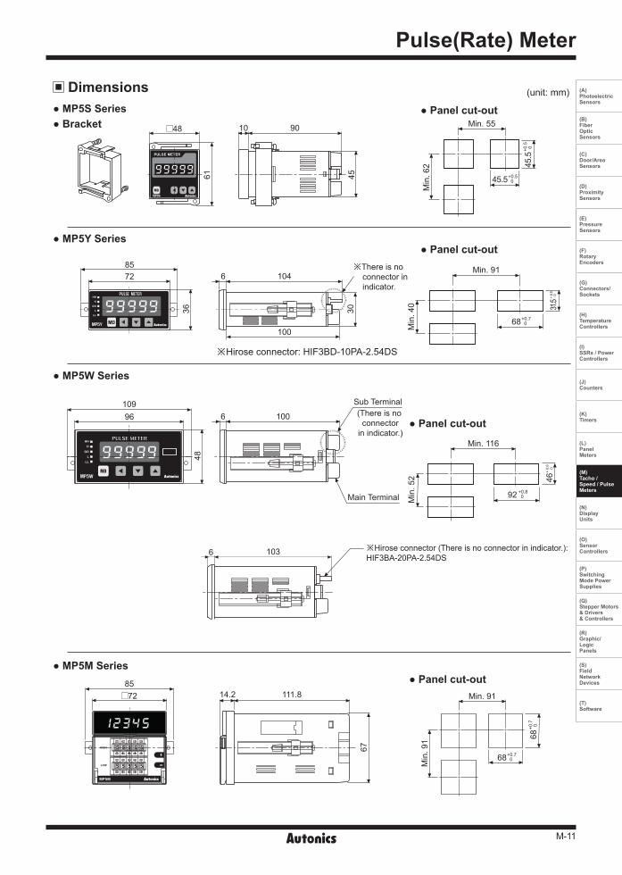
48 10 90
104
100
100
Sub Terminal
Main Terminal
(There is no connector
in indicator.)
1036
8572 14.2 111.8 Min. 91
Min
. 91
67
6
6
85
109
72
96
Min. 55
Min. 91
Min. 116
Min
. 62
Min
. 40
Min
. 52
45
36 30
4861
※There is no connector in indicator.
※Hirose connector: HIF3BD-10PA-2.54DS
※Hirose connector (There is no connector in indicator.): HIF3BA-20PA-2.54DS
Dimensions MP5S Series
MP5Y Series
MP5W Series
MP5M Series
Bracket Panel cut-out
Panel cut-out
Panel cut-out
Panel cut-out
(unit: mm)
68+0.70
92 +0.8 0
46+
0.6
0
45.5+0.5 0
45.5
+0.5
0
68+0.7 0
31.5 +
0.5
0
68+0
.7 0
M-12
MP5S/MP5Y/MP5W/MP5M Series
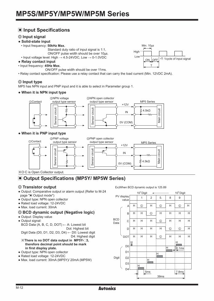
Input signal Solid-state input
• Input frequency: 50kHz Max. Standard duty ratio of input signal is 1:1,ON/OFF pulse width should be over 10.
• Input voltage level: High → 4.5-24VDC, Low → 0-1.0VDC Relay contact input • Input frequency: 45Hz Max.
ON/OFF pulse width should be over 11ms. • Relay contact specification: Please use a relay contact that can carry the load current (Min. 12VDC 2mA).
Input typeMP5 has NPN input and PNP input and it is able to select in Parameter group 1.
When it is PNP input type
When it is NPN input type
Min. 10
High
LowON OFF
T
*T: 1cycle of input signal
①Contact②PNP voltage output type sensor
※O·C is Open Collector output.
0V (COM)
0V (COM)
IN
IN
+12V
+12V
4.5kΩ
4.5kΩ
Sen
sor c
ircui
tS
enso
r circ
uit
Sen
sor c
ircui
tS
enso
r circ
uit
Mai
n ci
rcui
tM
ain
circ
uit
③PNP open collector output type sensor
①Contact②NPN voltage output type sensor
③NPN open collector output type sensor MP5 Series
MP5 Series
PV display value
A H
H
H
H
H
H
H
H
H
H
H
H
H
H
H
H
H
H
H
H H H
H
HH
H H
H
H
H
H
H
H
BCDData
Digit
B
C
D
DOT
D0
D1
D2
D3
D4
7.8ms39ms
5ms
0.1ms
104 Digit
Ex)When BCD dynamic output is 125.89
100 Digit
1 2 5. 8 9
Output Specifications (MP5Y/ MP5W Series)
Input Specifications
BCD dynamic output (Negative logic) Output: Display value Output signal:
BCD Data (A, B, C, D, DOT) ← A: Lowest bitDot: Highest bit
Digit Data (D0, D1, D2, D3, D4) ← D0: Lowest digit D4: Highest digit
※There is no DOT data output in MP5Y- 3,therefore decimal point should be markin first display plate.
Output type: NPN open collector Rated load voltage: 12-24VDC Max. load current: 30mA (MP5Y)/ 20mA (MP5W)
Transistor output Output: Comparative output or alarm output (Refer to M-24
page " Output mode") Output type: NPN open collector Rated load voltage: 12-24VDC Max. load current: 30mA
M-13
Pulse(Rate) Meter
(A) Photoelectric Sensors
(B) FiberOpticSensors
(C) Door/AreaSensors
(D) ProximitySensors
(E) PressureSensors
(F) RotaryEncoders
(G) Connectors/Sockets
(H)TemperatureControllers
(I)SSRs / PowerControllers
(J) Counters
(K) Timers
(L) PanelMeters
(M)Tacho /Speed / PulseMeters
(N)DisplayUnits
(O)SensorControllers
(P)SwitchingMode PowerSupplies
(Q)Stepper Motors & Drivers & Controllers
(R)Graphic/LogicPanels
(S)FieldNetworkDevices
(T) Software
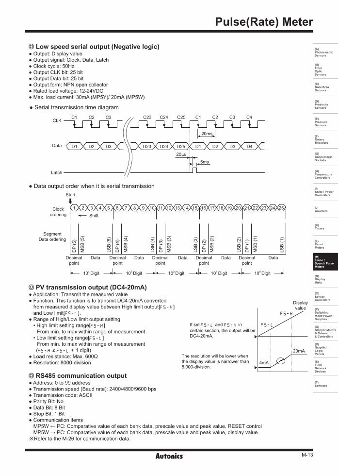
PV transmission output (DC4-20mA) Application: Transmit the measured value Function: This function is to transmit DC4-20mA converted
from measured display value between High limit output[FS-H]and Low limit[FS-L].
Range of High/Low limit output setting• High limit setting range[FS-H]
From min. to max within range of measurement• Low limit setting range[FS-L]
From min. to max within range of measurement(FS-H ≥ FS-L + 1 digit)
Load resistance: Max. 600Ω Resolution: 8000-division
RS485 communication output Address: 0 to 99 address Transmission speed (Baud rate): 2400/4800/9600 bps Transmission code: ASCII Parity Bit: No Data Bit: 8 Bit Stop Bit: 1 Bit Communication items
MP5W ← PC: Comparative value of each bank data, prescale value and peak value, RESET controlMP5W → PC: Comparative value of each bank data, prescale value and peak value, display value
※Refer to the M-26 for communication data.
CLKC1 C1
Data
Latch
D1 D1D2 D2D3 D3D23 D24 D25 D4
C2 C2C3 C3 C4
205ms
20ms
C23 C24 C25
1 142 153 164 175 186 197 208 219 2210 2311 2412 2513Clockordering Shift
Start
Data Data Data Data Data
104 Digit 103 Digit 102 Digit 101 Digit 100 Digit
Decimalpoint
Decimalpoint
Decimalpoint
Decimalpoint
Decimalpoint
DP
(5)
DP
(4)
DP
(3)
DP
(2)
DP
(1)
MS
B (5
)
MS
B (4
)
MS
B (3
)
MS
B (2
)
MS
B (1
)
LSB
(5)
LSB
(4)
LSB
(3)
LSB
(2)
LSB
(1)
SegmentData ordering
Displayvalue
FS-L
FS-H
20mA
4mA
Low speed serial output (Negative logic) Output: Display value Output signal: Clock, Data, Latch Clock cycle: 50Hz Output CLK bit: 25 bit Output Data bit: 25 bit Output form: NPN open collector Rated load voltage: 12-24VDC Max. load current: 30mA (MP5Y)/ 20mA (MP5W)
Data output order when it is serial transmission
Serial transmission time diagram
If set FS-L and FS-H incertain section, the output will beDC4-20mA.
The resolution will be lower when the display value is narrower than 8,000-division.

M-14
MP5S/MP5Y/MP5W/MP5M Series
Parameter Group Chart For Model
Monitoring Delay Operation Function Chart By Each Output Mode
Model
Parameter
MP5S-4NMP5Y-4NMP5W-4NMP5M-4N
MP5Y-41MP5Y-42
MP5Y-43
MP5Y-44
MP5Y-45
MP5W-41
MP5W-4AMP5W-42MP5W-43
MP5W-44MP5W-45
MP5W-46MP5W-47
MP5W-48MP5W-49
MP5M-41
MP5M-42
Par
amet
er g
roup
0 PSt;;
PSt ;
PSt L
PStLL
:PEK
lPEK
Par
amet
er g
roup
1
MODE
IN-A
IN-B
OVT-T
;YS
GVArD fDEFY
GVArD STArT
AUToA
AUToB
MEMO
Par
amet
er g
roup
2
pBANY
DOT
tVNT
PSt;;
PSt ;
PSt L
PStLL
PScaH
PScaY
PScbH
PScbY
DISpT
Par
amet
er g
roup
3 FS-;
FS-L
ADDR
BPS
REMOT
LOC
OVT-T STARD OVT-; OVT-L OVT-B OVT-I OVT-F
Comparative output limit functionStarting correction timer function
The parameter has different mode according to each model, therefore refer to " Parameter group chart of operation mode" and " Parameter".
: When selecting the operation mode, the parameter will be displayed.×: When selecting the operation mode, the parameter will not be displayed.
※ : Data bank (pBANK)setting is available in only MP5W-N.
M-15
Pulse(Rate) Meter
(A) Photoelectric Sensors
(B) FiberOpticSensors
(C) Door/AreaSensors
(D) ProximitySensors
(E) PressureSensors
(F) RotaryEncoders
(G) Connectors/Sockets
(H)TemperatureControllers
(I)SSRs / PowerControllers
(J) Counters
(K) Timers
(L) PanelMeters
(M)Tacho /Speed / PulseMeters
(N)DisplayUnits
(O)SensorControllers
(P)SwitchingMode PowerSupplies
(Q)Stepper Motors & Drivers & Controllers
(R)Graphic/LogicPanels
(S)FieldNetworkDevices
(T) Software
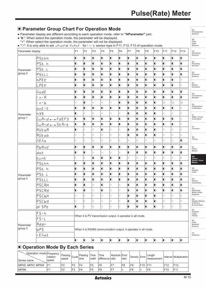
Parameter Group Chart For Operation Mode
Operation Mode By Each Series
Parameter display F1 F2 F3 F4 F5 F6 F7 F8 F9 F10 F11 F12 F13
Parametergroup 0
PSt;;
PSt ;
PSt L
PStLL
:PEK
lPEK
Parametergroup 1
MODE
IN-A
IN-B
OVT-T
;YS
GVArD fDEFY
GVArD STArT
AUToA
AUToB
MEMO
Parametergroup 2
pBANK
DOT
tVNT
PSt;;
PSt ;
PSt L
PStLL
PScaH
PScaY
PScbH
PScbY
DISpT
Parametergroup 3
FS-;When it is PV transmission output, it operates in all mode.
FS-L
ADDR
When it is RS485 communication output, it operates in all mode.BPS
REMOT
Operation mode
Series name
Frequencyrotationspeed
Passingspeed Cycle Passing
timeTime width
Time difference
Absoluteratio
Errorratio Density Error Length
measurement Interval Multiplication
MP5S, MP5Y, MP5W F1 F2 F3 F4 F5 F6 F7 F8 F9 F10 F11 F12 F13MP5M F1 F2 F3 F4 F5 F6 F7 × F8 × F9 F10 F11
Parameter display are different according to each operation mode, refer to " Parameter" part. " ": When select the operation mode, the parameter will be displayed.
"×": When select the operation mode, the parameter will not be displayed. " ": It is only able to set NPn:For PNp:F for IN-B sensor type in F11, F12, F13 of operation mode.
M-16
MP5S/MP5Y/MP5W/MP5M Series
Parameter Parameter group 0
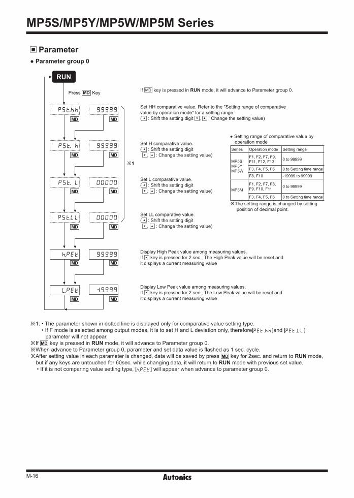
※1: • The parameter shown in dotted line is displayed only for comparative value setting type. • If F mode is selected among output modes, it is to set H and L deviation only, therefore[PET.;;]and [PET.LL]
parameter will not appear.※If MD key is pressed in RUN mode, it will advance to Parameter group 0. ※When advance to Parameter group 0, parameter and set data value is flashed as 1 sec. cycle. ※After setting value in each parameter is changed, data will be saved by press MD key for 2sec. and return to RUN mode,
but if any keys are untouched for 60sec. while changing data, it will return to RUN mode with previous set value.• If it is not comparing value setting type, [:PEK] will appear when advance to parameter group 0.
If MD key is pressed in RUN mode, it will advance to Parameter group 0.
Setting range of comparative value byoperation mode
Set HH comparative value. Refer to the "Setting range of comparativevalue by operation mode" for a setting range.( : Shift the setting digit , : Change the setting value)
Set H comparative value.( : Shift the setting digit
, : Change the setting value)
Set L comparative value.( : Shift the setting digit
, : Change the setting value)
Set LL comparative value.( : Shift the setting digit
, : Change the setting value)
Display High Peak value among measuring values.If key is pressed for 2 sec., The High Peak value will be reset andit displays a current measuring value
Display Low Peak value among measuring values.If key is pressed for 2 sec., The Low Peak value will be reset andit displays a current measuring value
※The setting range is changed by setting position of decimal point.
Series Operation mode Setting range
MP5SMP5Y MP5W
F1, F2, F7, F9, F11, F12, F13 0 to 99999
F3, F4, F5, F6 0 to Setting time range
F8, F10 -19999 to 99999
MP5MF1, F2, F7, F8, F9, F10, F11 0 to 99999
F3, F4, F5, F6 0 to Setting time range
※1
Press MD Key
99999
99999
00000
00000
PSt;;
PSt ;
PSt L
PStLL
:PEK 99999
`9999lPEK
RUN
MD
MD
MD
MD
MD
MD
MD
MD
MD
MD
MD
MD
M-17
Pulse(Rate) Meter
(A) Photoelectric Sensors
(B) FiberOpticSensors
(C) Door/AreaSensors
(D) ProximitySensors
(E) PressureSensors
(F) RotaryEncoders
(G) Connectors/Sockets
(H)TemperatureControllers
(I)SSRs / PowerControllers
(J) Counters
(K) Timers
(L) PanelMeters
(M)Tacho /Speed / PulseMeters
(N)DisplayUnits
(O)SensorControllers
(P)SwitchingMode PowerSupplies
(Q)Stepper Motors & Drivers & Controllers
(R)Graphic/LogicPanels
(S)FieldNetworkDevices
(T) Software
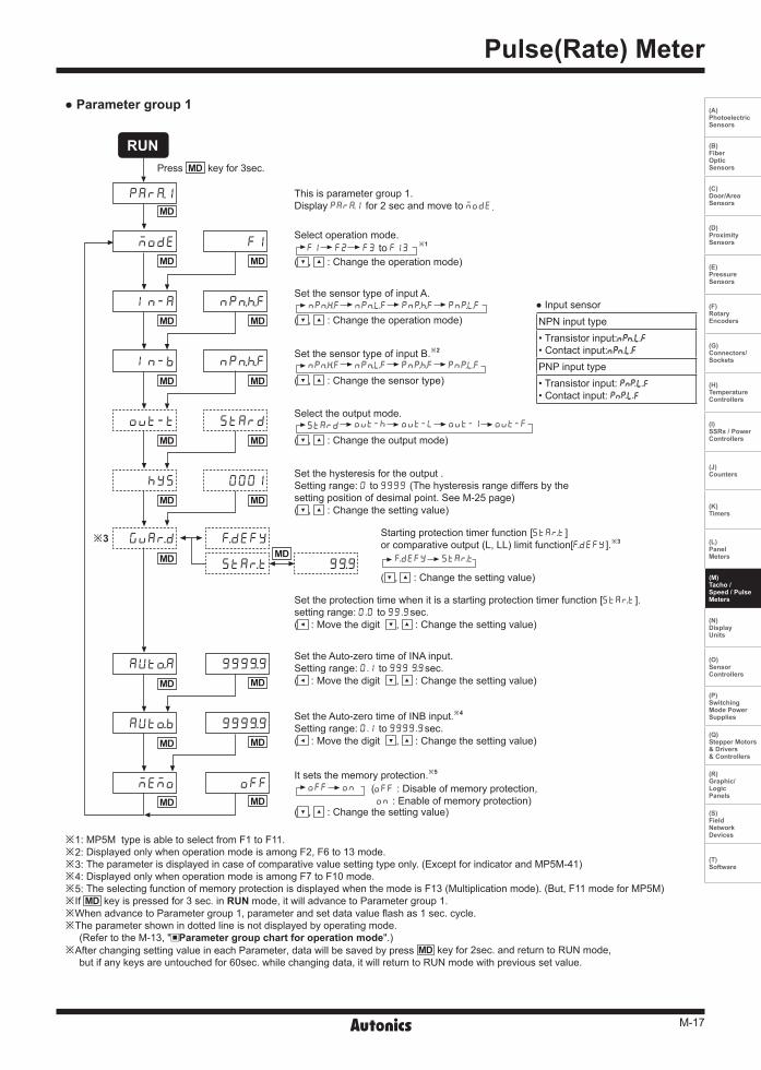
It sets the memory protection.※5 OFF ON
( , : Change the setting value)
Select the output mode. ( , : Change the output mode)
Set the sensor type of input B.※2
( , : Change the sensor type)
Set the sensor type of input A.
( , : Change the operation mode) NPnhF NPnlF PNp:F PNplF
Select operation mode.
( , : Change the operation mode) F1 F2 F3 to F13
Press MD key for 3sec.
Parameter group 1
※1: MP5M type is able to select from F1 to F11. ※2: Displayed only when operation mode is among F2, F6 to 13 mode. ※3: The parameter is displayed in case of comparative value setting type only. (Except for indicator and MP5M-41) ※4: Displayed only when operation mode is among F7 to F10 mode.※5: The selecting function of memory protection is displayed when the mode is F13 (Multiplication mode). (But, F11 mode for MP5M) ※If MD key is pressed for 3 sec. in RUN mode, it will advance to Parameter group 1. ※When advance to Parameter group 1, parameter and set data value flash as 1 sec. cycle.※The parameter shown in dotted line is not displayed by operating mode.
(Refer to the M-13, " Parameter group chart for operation mode".)※After changing setting value in each Parameter, data will be saved by press MD key for 2sec. and return to RUN mode,
but if any keys are untouched for 60sec. while changing data, it will return to RUN mode with previous set value.
This is parameter group 1.Display PARa1 for 2 sec and move to MODE.
Set the hysteresis for the output .Setting range: 0 to 9999 (The hysteresis range differs by thesetting position of desimal point. See M-25 page)( , : Change the setting value)
Set the protection time when it is a starting protection timer function [STArT].setting range: 0.0 to 99.9sec.( : Move the digit , : Change the setting value)
Set the Auto-zero time of INA input.Setting range: 0.1 to 999 (9sec.( : Move the digit , : Change the setting value)
Set the Auto-zero time of INB input.※4
Setting range: 0.1 to 9999.9sec.( : Move the digit , : Change the setting value)
(OFF : Disable of memory protection,ON : Enable of memory protection)
Input sensorNPN input type• Transistor input:• Contact input:PNP input type• Transistor input: • Contact input:
※1
NPnhF NPnlF PNp:F PNplF
STARD OVT-; OVT-L OVT-1 OVT-F
Starting protection timer function [STArT]or comparative output (L, LL) limit function[fDEFY].※3
( , : Change the setting value)
fDEFY STArT
PARa1
MODE
IN-A
IN-B
OVT-T
;YS
GVArD fDEFY
STArT 9(9
999(9
999(9
OFF
AUToA
AUToB
MEMO
STARD
0001
NPn:F
NPn:F
F1
MD
MD
MD
MD
MD
MD
MD
MD
MD
MD
MD
MD
MD
MD
MD
MD
MD
MD MD
RUN
※3
M-18
MP5S/MP5Y/MP5W/MP5M Series
※2
※1
※3
Setting range of comparative valueby operation mode
Time range by time unit
※ The setting range is changed bysetting position of decimal point.
Series Operation mode Setting range
MP5SMP5Y MP5W
F1, F2, F7, F9, F11, F12, F13 0 to 99999
F3, F4, F5, F6
0 to Settingtime range
F8, F10 -19999 to99999
MP5M
F1, F2, F7, F8,F9, F10, F11 0 to 99999
F3, F4, F5, F6 0 to Settingtime range
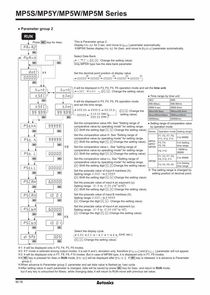
SEC MIN999.99sec. 999.99min.9999.9 sec. 9999.9min.99min59.9sec. 99hour59.9min.9hour59min59sec. 999hour59min.99999sec. 99999min.
※1: It will be displayed only in F3, F4, F5, F6 modes. ※2: If F mode is selected among output modes, it is set H and L deviation only, therefore [PSt;;] and [PStLL] parameter will not appear.※3: It will be displayed only in F7, F8, F9, F10 modes. But in case of MP5M type, it is displayed only in F7, F8 modes.※If MD key is pressed for 4sec.in RUN mode, [PARa2] will be displayed after [PARa1]. If MD key is released, it is advance to Parameter
group 2. ※When advance to Parameter group 2, parameter and set data value is flashed as 1sec cycle.※After setting value in each parameter is changed, data will be saved by press MD key for 2sec. and return to RUN mode,
but if any key is untouched for 60sec. while changing data, it will return to RUN move with previous set value.
Select Data Bank. ( , : Change the setting value) Only MP5W type has the data bank parameter.
It will be displayed in F3, F4, F5, F6 operation mode and set the time unit. ( , : Change the setting value)
It will be displayed in F3, F4, F5, F6 operation modeand set the time range.
( , :Change the setting value)
Set the comparative value HH. See "Setting range of comparative value by operating mode" for setting range. ( :Shift the setting digit , :Change the setting value)
Set the comparative value H. See "Setting range ofcomparative value by operating mode" for setting range. ( :Shift the setting digit , Change the setting value)
Set the comparative value L. See "setting range ofcomparative value by operating mode" for setting range.( :Shift the setting digit , Change the setting value)
Set the comparative value LL. See "Setting range ofcomparative value by operating mode" for setting range.( :Shift the setting digit , Change the setting value)
Set the prescale value of input A mantissa (X).Setting range: 0.0001 to 9.9999
( :Shift the setting digit , :Change the setting value)
Set the prescale value of input A an exponent (y).Setting range: 10-9 to 10 09 (10-9 to109)( :Shift the setting digit , :Change the setting value)
Set the prescale value of input B mantissa (X).Setting range: 0.0001 to 9.9999
( :Change the digit , : Change the setting value)
Set the prescale value of input A an exponent (y).Setting range: 10-9 to 10 09 (10-9 to 109)( :Change the digit , :Change the setting value)
Set the decimal point position of display value.
This is Parameter group 2.Display PARa2 for 2 sec. and move to [DOT] parameter automatically. ※MP5W Series display PARa2 for 2sec. and move to [pBANK] parameter automatically.
Press MD key for 4sec.
1 2
00000 000)0 00)00 0)000 )0000
tSEC tM M
999.99 9999.9 99.59.9
999.59 (min.)
Parameter group 2
Select the display cycle. (Unit: sec.)
( , :Change the setting value)
0.05 0.5 1 2 4 8
PARa2ㅔㅔㅔㅔ
DOT
00000
PSt;;
PSt ;
PSt L
PStLL
PScaH
PScaY
PScbH
PScbY
DISpT )05
10 01
^0000
^0000
10 01
99999
99999
00000
00000
pBANY 1
tVNT tVNT
tM N
tM N
99 (99
tSEC
tSEC
99 (99
MD
MD
MD
MD
MD
MD
MD
MD
MD
MD
MD
MD
MD
MD
MD
MD
MD
MD
MD
MD
MD
MD
MD
MD
MD
RUN
99999 9.59.59 (sec.)
M-19
Pulse(Rate) Meter
(A) Photoelectric Sensors
(B) FiberOpticSensors
(C) Door/AreaSensors
(D) ProximitySensors
(E) PressureSensors
(F) RotaryEncoders
(G) Connectors/Sockets
(H)TemperatureControllers
(I)SSRs / PowerControllers
(J) Counters
(K) Timers
(L) PanelMeters
(M)Tacho /Speed / PulseMeters
(N)DisplayUnits
(O)SensorControllers
(P)SwitchingMode PowerSupplies
(Q)Stepper Motors & Drivers & Controllers
(R)Graphic/LogicPanels
(S)FieldNetworkDevices
(T) Software
※1
※2
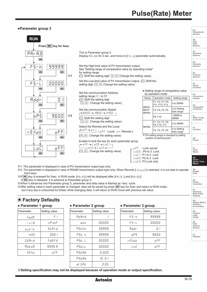
※1: The parameter is displayed in case of PV transmission output type only.※2: The parameter is displayed in case of RS485 transmission output type only. When Remote [REMOT] is selected, it is not able to operate
front keys.※If MD key is pressed for 5sec. in RUN mode, [PARa3] will be displayed after [PARa1] and [PARa2].
If MD key is released, it is advance to Parameter group 3.※When it advances into Parameter group 3, parameter and data value is flashed as 1sec. cycle.※After setting value in each parameter is changed, data will be saved by press MD key for 2sec and return to RUN mode,
but if any key is untouched for 60sec while changing data, it will return to RUN move with previous set value.
Parameter group 3
Factory Defaults
※Setting specification may not be displayed because of operation mode or output specification.
Parameter 1 group Parameter 2 group Parameter 3 groupParameter Setting value
MODE F1
IN-A NPn:F
OVT-T STARD
;YS 0001
GUArD fDEFY
AUToA 9999.9
MEMO OFF
Parameter Setting value
pBANY 1
DOT 00000
PSt;; 99999
PSt ; 99999
PSt L 00000
PStLL 00000
PStaH 6.000
PStaY 10 01
DISpT 0.05
Parameter Setting value
FS-; 99999
FS-L 00000
ADDR 01
BPS 9600
REMOT OFF
LOC OFF
This is Parameter group 3.Display PARa3 for 2 sec. and move to [FS-;] parameter automatically.
Press MD key for 5sec.
Set the High-limit value of PV transmission output.See "Setting range of comparative value by operating mode"for setting range ( :Shift the setting digit , :Change the setting value)
Set the Low-limit value of PV transmission output. ( :Shift the setting digit , :Change the setting value)
Set the communication Address.setting range: 01 to 99
( :Shift the setting digit , : Change the setting value) Set the communication Speed. 9600 4800 2400
( :Shift the setting digit , : Change the setting value)
Select the Remote and the Local. OFF ON ( OFF : Local, ON: Remote ) ( , : Change the setting value)
Enable to lock the key for each parameter group OFF LOc0 LOc1
LOc3 LOc2
( , : Change the setting value)
Setting range of comparative value by operation mode
Series Operation mode Setting range
MP5SMP5Y MP5W
F1, F2, F7, F9, F11, F12, F13 0 to 99999
F3, F4, F5, F6 0 to Settingtime range
F8, F10 -19999 to99999
MP5M
F1, F2, F7, F8, F9, F10, F11 0 to 99999
F3, F4, F5, F6 0 to Settingtime range
※The setting range is changed by setting position of decimal point.
OFF : Lock cancel LOc0 : P0 to 3 LockLOc1: P1 to 3 LockLOc2: P2 to 3 LockLOc3: P3 Lock only
PARa3
FS-;
FS-L
ADDR
BPS
REMOT
LOC
01
9600
OFF
OFF
99999
00000
MD
MD
MD
MD
MD
MD
MD
MD
MD
MD
MD
MD
MD
RUN
M-20
MP5S/MP5Y/MP5W/MP5M Series
MP5 Series
MP5Series
Photoelectricsensor
Encoder
Sensor A
Input A
Input A
Input B
display
Display
(1/t1) ×α (1/t3) ×α (1/t6) ×α
1 × α t1
1 × α t2
1 × α t4
1 × α t7
ta
t1 t2 t3 t4 t5 t6
t1 t2 t3 t4 t5 t6 t7
Holdinput
Holdinput
Sensor B
MP5 Series
MP5 Series
Input A
Display
t1 t2 t3 t4 t5 t6
t1 t3 t6
Holdinput
※ta: It requires min. 20ms for return time
※t1 to t6 should be over min. 20ms for measuring.
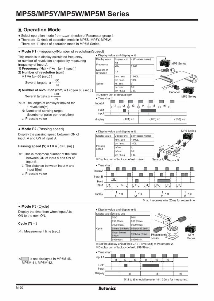
Operation Mode Select operation mode from ㅔㅔMODE (mode) of Parameter group 1. There are 13 kinds of operation mode in MP5S, MP5Y, MP5W.
There are 11 kinds of operation mode in MP5M Series.
Mode F1 (Frequency/Number of revolution/Speed)This mode is to display calculated frequencyor number of revolution or speed by measuringfrequency of Input A.1) Frequency (Hz) = f ×α [α= 1 (sec.) ] 2) Number of revolution (rpm)
= f ×α [α= 60 (sec.) ]
Several targets α = 60 N 3) Number of revolution (rpm) = f ×α [α= 60 (sec.) ]
Several targets α = 60L N※L= The length of conveyor moved for
1 revolution[m]N: Number of sensing target
(Number of pulse per revolution)α: Prescale value
Mode F2 (Passing speed)Display the passing speed between ON ofinput A and ON of input B.
Passing speed (V) = f × α [ α= L (m) ]
※f: This is reciprocal number of the timebetween ON of input A and ON of input B.
L: The distance between input A andinput B[m]
α: Prescale value
Mode F3 (Cycle)Display the time from when input A isON to the next ON.
Cycle (T) = t
※t: Measurement time [sec.]
※ is not displayed in MP5M-4N, MP5M-41, MP5M-42.
Display value and display unit
Display value and display unit
Display value and display unit
Time chart
Time chart
Time chart
※Display unit of default: rpm
※Display unit of factory default: m/sec.
※Set the display unit at the tVNT (Time unit) of Parameter 2.※Display unit of factory default: 999.99sec.
Display value Display unit α (Prescale value)
FrequencyHz 1 kHz 0.001
Number ofrevolution rps 1
Speed
mm / sec. 1,000L cm / sec. 100L m / sec. L m / min. 60L km / hour 3.6L
Display value Display unit α (Prescale value)
Passingspeed
mm / sec. 1,000L cm / sec. 100L m/sec L m/min 60L km / hour 3.6L
Display value Display unit
Cycle
SEC MIN 999.99sec. 999.99min.9999.9sec. 9999.9min.99min. 59.9sec. 99hour 59.9min.9hour 59min.59sec. 999hour 59min.
99999sec. 99999min.
M-21
Pulse(Rate) Meter
(A) Photoelectric Sensors
(B) FiberOpticSensors
(C) Door/AreaSensors
(D) ProximitySensors
(E) PressureSensors
(F) RotaryEncoders
(G) Connectors/Sockets
(H)TemperatureControllers
(I)SSRs / PowerControllers
(J) Counters
(K) Timers
(L) PanelMeters
(M)Tacho /Speed / PulseMeters
(N)DisplayUnits
(O)SensorControllers
(P)SwitchingMode PowerSupplies
(Q)Stepper Motors & Drivers & Controllers
(R)Graphic/LogicPanels
(S)FieldNetworkDevices
(T) Software
Sensor A Sensor B
t1 t2 t4 t7
ta
t1 t2 t3 t4 t5 t6 t7
L : Distance[m]
t1
t1 × α t3 × α t6 × α
t2 t3 t4 t5 t6
MP5Series
StampMotor
t1 t3
t1 t2 t3ta ta
MP5 Series
MP5 Series
※Display unit of factory specification : 999.99sec.
※ta: It requires min. 20ms for return time
※ta: It requires min. 20ms for return time
Display value and display unit
Display value and display unit
Display value and display unit
Time chart
Time chart
Time chart
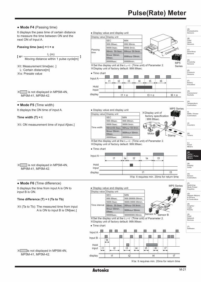
※Set the display unit at the tVNT (Time unit) of Parameter 2.※Display unit of factory default: 999.99sec.
※Set the display unit at the tVNT (Time unit) of Parameter 2.※Display unit of factory default: 999.99sec.
※Set the display unit at the tVNT (Time unit) of Parameter 2.※Display unit of factory default: 999.99sec
Display value Display unit
Passingtime
SEC MIN 999.99sec. 999.99min.9999.9sec. 9999.9min.99min. 59.9sec. 99hour 59.9min.9hour 59min.59sec. 999hour 59min.
99999sec. 99999min.
Display value Display unit
Time width
SEC MIN 999.99sec. 999.99min.9999.9sec. 9999.9min.99min59.9sec. 99hour 59.9min.9hour 59min.59sec. 999hour 59min.
99999sec. 99999min.
Display value Display unit
Time interval
SEC MIN 999.99sec. 999.99999.99min.9999.9sec. 9999.9999.99min.99min. 59.9sec. 99hour 59.9min.9hour 59min.59sec. 999hour 59min.
99999sec. 99999999.99min.
Mode F6 (Time difference)It displays the time from input A is ON toinput B is ON.
Time difference (T) = t (Ta to Tb)
※t (Ta to Tb): The measured time from inputA is ON to input B is ON[sec.]
※ is not displayed in MP5M-4N,MP5M-41, MP5M-42.
Mode F5 (Time width)It displays the ON time of input A.
Time width (T) = t
※t: ON measurement time of input A[sec.]
※ is not displayed in MP5M-4N,MP5M-41, MP5M-42.
Mode F4 (Passing time)It displays the pass time of certain distanceto measure the time between ON and the next ON of Input A.
Passing time (sec) = t × α
[ α= L (m) ]
Moving distance within 1 pulse cycle[m]
※t: Measurement time[sec .]L: Certain distance[m]
※α: Presale value
※ is not displayed in MP5M-4N,MP5M-41, MP5M-42.
Input A
display
Holdinput
Input A
display
Holdinput
Input A
Input B
display
Holdinput
M-22
MP5S/MP5Y/MP5W/MP5M Series
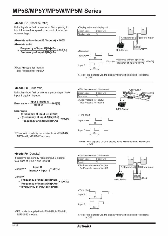
It displays how fast or late Input B comparing toInput A as well as speed or amount of Input, asa percentage.
Absolute ratio = (Input B / Input A) × 100%Absolute ratio
= Frequency of input B[Hz]×Bα ×100[%]
Frequency of input A[Hz]×Aα
※Aα: Prescale for input ABα: Prescale for input A
A Flow meter B Flow meter
LiquidMP5 Series
MP5 Series
Conveyer AConveyer B
Input A
Input B
Input B
Input B
Input A
Input A
fA
fA
fB
fB
※Hold: Hold signal is ON, the display value will be held until Hold signal is OFF.
※Hold: Hold signal is ON, the display value will be held until Hold signal is OFF.
※Hold: Hold signal is ON, the display value will be held until Hold signal is OFF.
fA
fB
Display value Display unitAbsolute ratio %
Display value Display unitError ratio %
Display value Display unitDensity %
Display value and display unit
Display value and display unit
Display value and display unit
Time chart
Time chart
Time chart
※Aα: Prescale for input A Bα: Prescale for input B
※Aα:Prescale value of input A Bα:Prescale value of input B
Display= Frequency of input B[Hz]×Bα
×100[%] Frequency of input A[Hz]×Aα
Mode F7 (Absolute ratio)
Mode F8 (Error ratio)It displays how fast or late as a percentage (%)for input B against input A.
Error ratio = Input B-Input A ×100[%] Input A
Error ratio (Frequency of input B[Hz]×Bα)
= - (Frequency of input A[Hz]×Aα) ×100[%] Frequency of input A[Hz]×Aα
※Error ratio mode is not available in MP5M-4N, MP5M-41, MP5M-42 models.
Mode F9 (Density)It displays the density ratio of input B against total sum of input A and input B.
Density = Input B ×100[%] Input A + Input B
Density
= Frequency of input B[Hz]×Bα ×100[%] (Frequency of input A[Hz]×Aα)
+ (Frequency of input B[Hz]×Bα)
※F8 mode is applied to MP5M-4N, MP5M-41, MP5M-42 models.
A Flow meter B Flow meter
MP5 Series
Liquid
M-23
Pulse(Rate) Meter
(A) Photoelectric Sensors
(B) FiberOpticSensors
(C) Door/AreaSensors
(D) ProximitySensors
(E) PressureSensors
(F) RotaryEncoders
(G) Connectors/Sockets
(H)TemperatureControllers
(I)SSRs / PowerControllers
(J) Counters
(K) Timers
(L) PanelMeters
(M)Tacho /Speed / PulseMeters
(N)DisplayUnits
(O)SensorControllers
(P)SwitchingMode PowerSupplies
(Q)Stepper Motors & Drivers & Controllers
(R)Graphic/LogicPanels
(S)FieldNetworkDevices
(T) Software
MP5 Series
Photoelectricsensor
Photoelectric sensor
MP5Series
A
A
B
B
MP5 Series
MP5 Series
Conveyer AConveyer B
Input A Input BfA fB
※Hold: Hold signal is ON, the display value will be held until Hold signal is OFF.
ta
ta
tb
tb
1 12 23 34
1 2 3 41 2 3 4 5 6
RESETinput
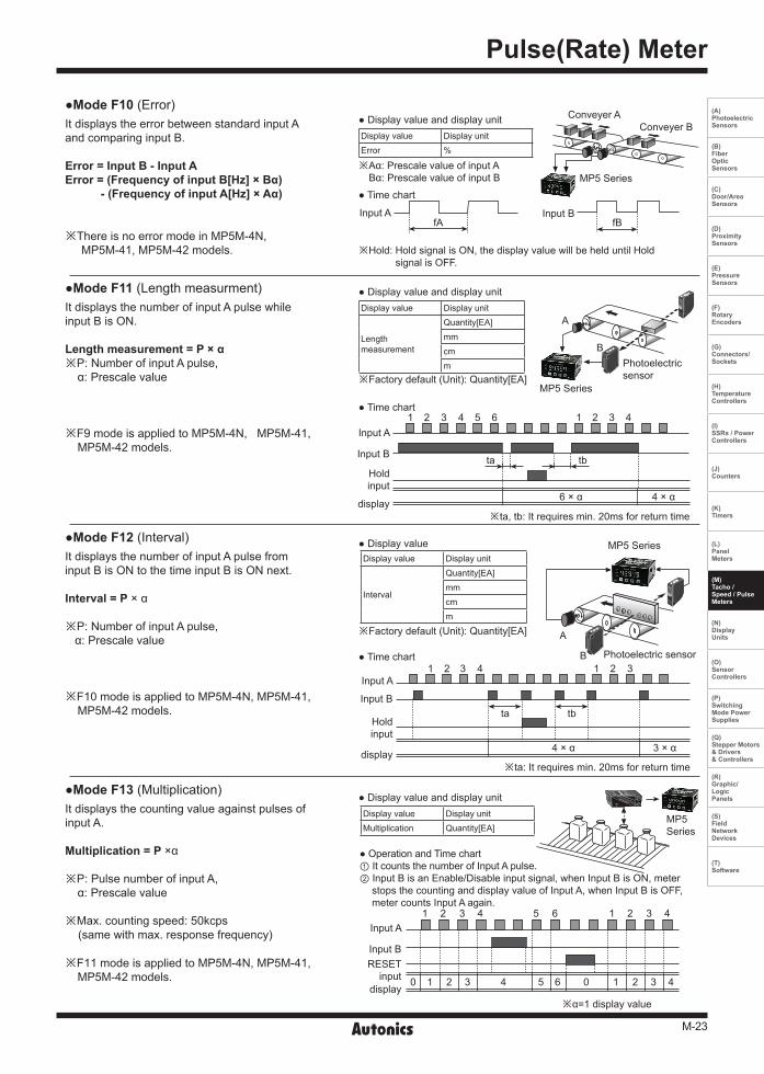
※ta, tb: It requires min. 20ms for return time
※ta: It requires min. 20ms for return time
※α=1 display value
6 × α
4 × α 3 × α
4 × α
Display value Display unitError %
Display value Display unitMultiplication Quantity[EA]
Display value Display unit
Lengthmeasurement
Quantity[EA]mmcmm
Display value Display unit
Interval
Quantity[EA]mmcmm
Display value and display unit
Display value and display unit
Display value and display unit
Display value
Time chart
Time chart
Time chart
※Aα: Prescale value of input A Bα: Prescale value of input B
Operation and Time chart① It counts the number of Input A pulse.② Input B is an Enable/Disable input signal, when Input B is ON, meter
stops the counting and display value of Input A, when Input B is OFF, meter counts Input A again.
※Factory default (Unit): Quantity[EA]
※Factory default (Unit): Quantity[EA]
11 22 33 5 6 00 44
1 12 23 34 5 6 4
Mode F11 (Length measurment)It displays the number of input A pulse whileinput B is ON.
Length measurement = P × α※P: Number of input A pulse,
α: Prescale value
※F9 mode is applied to MP5M-4N, MP5M-41, MP5M-42 models.
Mode F10 (Error)It displays the error between standard input Aand comparing input B.
Error = Input B - Input AError = (Frequency of input B[Hz] × Bα) - (Frequency of input A[Hz] × Aα)
※There is no error mode in MP5M-4N, MP5M-41, MP5M-42 models.
Mode F12 (Interval)It displays the number of input A pulse frominput B is ON to the time input B is ON next.
Interval = P × α
※P: Number of input A pulse, α: Prescale value
※F10 mode is applied to MP5M-4N, MP5M-41, MP5M-42 models.
Mode F13 (Multiplication)It displays the counting value against pulses of input A.
Multiplication = P ×α
※P: Pulse number of input A,α: Prescale value
※Max. counting speed: 50kcps (same with max. response frequency)
※F11 mode is applied to MP5M-4N, MP5M-41, MP5M-42 models.
Input A
Input B
display
Holdinput
Input A
Input B
display
Holdinput
Input A
Input B
display
M-24
MP5S/MP5Y/MP5W/MP5M Series
Hys
Hys
Hys
Hys
Comparativevalue
Comparativevalue
Comparativevalue
Comparativevalue
Press ( M + )key formemorizing the settingvalue at the same time
※1
※2
(High-limit)H deviation
Power
Setting value memory
ONOFF
ONOFF
ONOFF
ONOFF
L deviation output
H deviation output
Setting value
(Low-limit)L deviation
Output
Output
Output
Output
HH
HH
HH
HH
HH
HH
H
H
H
H
H
H
L
L
L
L
L
L
LL
LL
LL
LL
LL
LL
GO
GO
GO
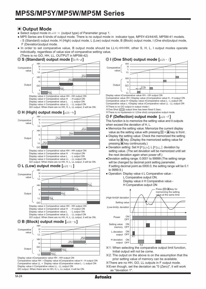
Output Mode Select output mode in OUT-T (output type) of Parameter group 1. MP5 Series are 6 kinds of output mode. There is no output mode in indicator type, MP5Y-43/44/45, MP5M-41 models.
- S (Standard) output mode, H (High) output mode, L (Low) output mode, B (Block) output mode, I (One shot)output mode,F (Deviation)output mode.
In order to set comparative value, B output mode should be LL<L<H<HH, other S, H, L, I output modes operate individually, regardless of value size of comparative setting value.(There is no GO, HH, LL, OUTPUT in MP5M-42) S (Standard) output mode [STARD] I (One Shot) output mode [OUT-1]
F (Deflection) output mode [OUT-F]This function is to memorize the setting value and it outputs when exceed the deviation of H, L. Memorize the setting value: Memorize the current display
value as the setting value with pressing M + key is front . Display the setting value: Check the memorized the setting
value by key. (Display the memorized setting value for pressing key continuously.)
Deviation setting: Set H [PSt;], L [PStL] deviation by setting value. (The set deviation will be memorized until set the next deviation again when power off.)
Deviation setting range: 0.0001 to 99999 (The setting range will be changed by decimal point setting parameter.If setting decimal point as 0000.0, the setting range will be 0.1 to 9999.9.)
Operation: Display value ≤ L Comparative value -L Comparative output ON,Display value ≥ H Comparative value -H Comparative output ON
※1: When selecting the comparative output limit function, Initial output will not be come.
※2: The output on the above is on the assumption that the prior setting value of memory can be available.
※There are no HH, GO, LL outputs in F output mode.※Even though, set the deviation as "0 (Zero)", it will work
as "deviation 1".
H (High) output mode [OUT-;]
L (Low) output mode [OUT-L]
B (Block) output mode [OUT-B]
Display value ≥Comparative value HH - HH output ONComparative value HH >Display value ≥Comparative value H - H output ONComparative value H >Display value ≥Comparative value L - L output ONComparative value L >Display value ≥Comparative value LL - LL output ON
Display value ≥ Comparative value HH - HH output ONDisplay value ≥ Comparative value H - H output ONDisplay value ≤ Comparative value L - L output ONDisplay value ≤ Comparative value LL - LL output ONGO output: When there are no HH, H, L, LL output, it will be ON.
Display value ≥ Comparative value HH - HH output ONDisplay value ≥ Comparative value H - H output ONDisplay value ≥ Comparative value L - L output ONDisplay value ≥ Comparative value LL - LL output ONGO output: When there are no HH, H, L, LL output, it will be ON.
Display value ≤ Comparative value HH - HH output ONDisplay value ≤ Comparative value H - H output ONDisplay value ≤ Comparative value L - L output ONDisplay value ≤ Comparative value LL - LL output ONGO output: When there are no HH, H, L, LL output, it will be ON.
Display value ≥Comparative value HH - HH output ONComparative value HH >Display value ≥Comparative value H - H output ONComparative value LL < Display value ≤Comparative value L - L output ONDisplay value ≤ Comparative value LL - LL output ONGO output: When there are no HH, H, L, LL output, it will be ON.
※There is no GO output in output mode I. ※One Shot ( ) output time has been fixed 0.3sec.※There is no Hysteresis in I (One shot) comparative output mode.
Hys
Hys
Hys
Hys
Hys
Hys
Hys
Hys
Hys
Hys
Hys
Hys
HH
HH
H
H
L
L
LL
LL
GO
0.3s
Comparativevalue
Output
HH
HH
H
H
L
L
LL
LL
GO

M-25
Pulse(Rate) Meter
(A) Photoelectric Sensors
(B) FiberOpticSensors
(C) Door/AreaSensors
(D) ProximitySensors
(E) PressureSensors
(F) RotaryEncoders
(G) Connectors/Sockets
(H)TemperatureControllers
(I)SSRs / PowerControllers
(J) Counters
(K) Timers
(L) PanelMeters
(M)Tacho /Speed / PulseMeters
(N)DisplayUnits
(O)SensorControllers
(P)SwitchingMode PowerSupplies
(Q)Stepper Motors & Drivers & Controllers
(R)Graphic/LogicPanels
(S)FieldNetworkDevices
(T) Software
Prescale function This prescale function allows to multiply the number of pulse or pulse length by a variable (X × 10y ) then display specification of measurement. It will display frequency or RPM from prescale value by measuring the input frequency. For example, what is prescale value α when rpm is displayed?
RPM = f×α = f×60× (1/ N)= f×60× (1/ 4)= f×60×0.25= f×15
※f: Input pulse (Frequency) per sec.※α: Prescale value※N: Pulse number per 1 revolution
Prescale value (α=15) settingSet Prescale value (α) as (X) and (y) separately in PScaH, PScaY (PScbH, PScbY) of Parameter group 2.Set Prescale (α=15) as (X):1.5000, (y):10It is also able to get the same display valueeven though set as X=0.1500, y=10X setting range: 0.0001 to 9.9999Y setting range: 10-9 to 109
Peak value monitoring function It saves High Peak value or :PEK or Low Peak value lPEK against display value. It can check in parameter group 0, the High Peak [:PEK]
value or the Low Peak [lPEK] value will be continuously saved during checking.
Refer to Parameter group 0 for Reset.
Monitoring delay function It controls stably to limit L, LL output until certain output is displayed or all output until the equipment will be in a stable status against various change of input such as the staring current when the motor is running after power on. (select this at GVAㅔㅔㅔrD mode of parameter 1 group)
MP5Series
Comparativesetting value
L, LL
Output
Delay time of monitoring
No ouput
This point where the comparativeoutput limit function is released.
Function
Input
Sampling
Inner Counting
Comparativevalue
Output
HH
HH
H
H
L
L
LL
LL
GO
This point where the comparative output limit function is released.
Comparativevalue
Output
HH
HH
H
H
L
L
LL
LL
GO
Selection of display interval It measures and displays reciprocal number of measuring time to detect target. Measuring accuracy may be dropped because the measuring time of interval is short, if the target is revolving with high speed. It is able to change the display cycle in range of 0.05/0.5/1/2/4/8sec.) and displays the average value of measuring value then able to maintain measuring accuracy when revolving with high speed. In case of preset output type, the response can be delayed when the measuring time is long. Therefore, please adjust the measuring time properly.
※Select display sampling period in parameter 2.
① Starting correction timer function(STArT mode of Parameter group 1)This function is to inhibit the output come for the setting time. (Time setting range 0.0 to 99.9sec.)Applicable output mode: S, H, L, B, I, F mode
② Comparative output limit function(fDEFY mode of Parameter1 group)This function is to limit the LL, L output before H or HH output.Applicable output mode: S, B, F mode
The output mode is S output mode(Initial operation after supplying power)
The output mode is B output mode(Initial operation after supplying power)
※Initial L, LL comparative output does not operate after supplying power.
※Eac setting value of HH, H, L, LL is not effected by each other. Therefore, HH value may be equal or lower than LL value.
※Initial L, LL comparative output does not operate after supplying power.
※Each setting value of HH, H, L, LL effects on each other. Therefore, setting value should be LL<L<H<HH in sequence.

M-26
MP5S/MP5Y/MP5W/MP5M Series
Comparativesetting value
H, HH
A A
Return point of output whenthere is no hysteresis value
A: Hysteresis value
Comparativesetting value
L, LL
Output H, HH
Output L, LL
DOT position Setting range00000 0000 to 9999 0000.0 000.0 to 999.9 000.00 00.00 to 99.99 00.000 0.000 to 9.999 0.0000 0.000 to 0.999
Parameter Parameter0 group
Parameter1 group
Parameter2 group
Parameter3 group
OFF - - - -LOC0 LOC1 - LOC2 - - LOC3 - - -
Pin LOC mode Remarkh0 (Hardware
Lock0) Check:, Change: Factorydefault
h1 (HardwareLock1) Check:, Change:×
h2 (HardwareLock2) Check:×, Change:×
Comparativevalue
Output
This point where the comparativeoutput limit function is released.
H deviationSetting value
L deviation
HL
SW LOC mode
h1(Hardware Lock1)
1 2 ONOFF
Check:, Change:
h1(Hardware Lock1)
1 2 ONOFF
Check:, Change:×
h2(Hardware Lock2)
1 2 ONOFF
Check:×, Change:× 1 2 ONOFF
The output mode is F output mode(Initial operation after supplying power)
Lock setting function This function is to set the enable or disable of each Para- meter and mode changes.
※Setting pin for Lock setting is located on internal PCB.
MP5M Series
※ It is possible to lock or unlock after supplied power in Inner hardware Lock setting.
Data bank switching function This is a function to save comparative setting value and prescale value in each data bank (Data Bank 1, Data Bank 2) in order to make easy to use necessary data saved in each data bank. When terminal No.3 and 5 are open, comparativev value
and prescale value in Data Bank 1 will be activated. When terminal No.3 and 5 are shorted, comparative
value and prescale value in Data Bank 2 will be activated. How to save comparative value and prescale value in
each Data Bank: Enter into parameter 2 group pBANK and select the Data Bank where you save the data. Then, save each comparative setting value and prescale value.
※Data bank switching function is in MP5W Series only.
※Initial L comparative output does not operate after supplying power.
※The comparative output limit function will be released at the setting value (Standard setting).
Hysteresis function Set the Hysteresis value (A) for comparative setting value in order to prevent unstable operation due to output is ON/OFF frequently.
※ -: Unlock, : Lock※Lock setting is available in Parameter 3 group.
Inner hardware Lock setting function This function is to lock LOC in Parameter 3 group by Inner hardware Lock function in order to prevent wrong setting. MP5S, MP5Y, MP5W Series
※It is able to set "0" but when set "0", the actual operation will be as "1".
※The initial setting value is 0001.※It is able to set in [;YS] mode of Parameter group 1.
Auto-Zero time setting function If there is no pulse input within setting time (Auto-zero time), it regards as the input signal is cut off then make the value as "00000" forcibly. Note that the Auto-zero time setting should be longer than the widest interval of input pulse. Otherwise it may be difficult to make the display value as "00000". Auto-zero time setting range: 0.1 to 9999.9sec.
(Factory default setting: 9999.9sec.) When the display value is [00000], each output will
respond to how it was programmed for "0". Set the time in [AVToA] and [AUToB] mode of parameter
group 1.Be sure that some operation modes are not displayed. Please refer to M-14.

M-27
Pulse(Rate) Meter
(A) Photoelectric Sensors
(B) FiberOpticSensors
(C) Door/AreaSensors
(D) ProximitySensors
(E) PressureSensors
(F) RotaryEncoders
(G) Connectors/Sockets
(H)TemperatureControllers
(I)SSRs / PowerControllers
(J) Counters
(K) Timers
(L) PanelMeters
(M)Tacho /Speed / PulseMeters
(N)DisplayUnits
(O)SensorControllers
(P)SwitchingMode PowerSupplies
(Q)Stepper Motors & Drivers & Controllers
(R)Graphic/LogicPanels
(S)FieldNetworkDevices
(T) Software
①
①
②
B (-) B (-)
A (+) A (+)
A (+) B (-)MP5
Series
A (+) B (-)MP5
Series
A (+) B (-)MP5
Series
Mastersystem
MP5Series
Terminating Resistance(100 to 120Ω)
01 02 30
31
Master
STX 101 100 R/W X/D ETX CRC
STX
STX
ACK
STX
ADR
CMD
TXT
ETX
CRC
ADR
ADR
CMD
CMD
TXT
TXT
ETX
ETX
CRC
CRC
A B C
MP5Series
Calculation range of CRC Check Sum
StartCode
AddressCode
HeaderCode
ENDCode
Text CRCCode
SEC MIN 999.99sec. 999.99min.9999.9sec. 9999.9min.99min59.9sec. 99hour59.9min.9hour59min59sec. 999hour59min.99999sec. 99999min.
0 1 2 3 4 5 6 7 8 9 A B C D E F 0 0×00 0×5E 0×BC 0×E2 0×61 0×3F 0×DD 0×83 0×C2 0×9C 0×7E 0×20 0×A3 0×FD 0×1F 0×41 1 0×9D 0×C3 0×21 0×7F 0×FC 0×A2 0×40 0×1E 0×5F 0×01 0×E3 0×BD 0×3E 0×60 0×82 0×DC 2 0×23 0×7D 0×9F 0×C1 0×42 0×1C 0×FE 0×A0 0×E1 0×BF 0×5D 0×03 0×80 0×DE 0×3C 0×62 3 0×BE 0×E0 0×02 0×5C 0×DF 0×81 0×63 0×3D 0×7C 0×22 0×C0 0×9E 0×1D 0×43 0×A1 0×FF 4 0×46 0×18 0×FA 0×A4 0×27 0×79 0×9B 0×C5 0×84 0×DA 0×38 0×66 0×E5 0×BB 0×59 0×07 5 0×DB 0×85 0×67 0×39 0×BA 0×E4 0×06 0×58 0×19 0×47 0×A5 0×FB 0×78 0×26 0×C4 0×9A 6 0×65 0×3B 0×D9 0×87 0×04 0×5A 0×B8 0×E6 0×A7 0×F9 0×1B 0×45 0×C6 0×98 0×7A 0×24 7 0×F8 0×A6 0×44 0×1A 0×99 0×C7 0×25 0×7B 0×3A 0×64 0×86 0×D8 0×5B 0×05 0×E7 0×B9 8 0×8C 0×D2 0×30 0×6E 0×ED 0×B3 0×51 0×0F 0×4E 0×10 0×F2 0×AC 0×2F 0×71 0×93 0×CD 9 0×11 0×4F 0×AD 0×F3 0×70 0×2E 0×CC 0×92 0×D3 0×8D 0×6F 0×31 0×B2 0×EC 0×0E 0×50 A 0×AF 0×F1 0×13 0×4D 0×CE 0×90 0×72 0×2C 0×6D 0×33 0×D1 0×8F 0×0C 0×52 0×B0 0×EE B 0×32 0×6C 0×8E 0×D0 0×53 0×0D 0×EF 0×B1 0×F0 0×AE 0×4C 0×12 0×91 0×CF 0×2D 0×73 C 0×CA 0×94 0×76 0×28 0×AB 0×F5 0×17 0×49 0×08 0×56 0×B4 0×EA 0×69 0×37 0×D5 0×8B D 0×57 0×09 0×EB 0×B5 0×36 0×68 0×8A 0×D4 0×95 0×CB 0×29 0×77 0×F4 0×AA 0×48 0×16 E 0×E9 0×B7 0×55 0×0B 0×88 0×D6 0×34 0×6A 0×2B 0×75 0×97 0×C9 0×4A 0×14 0×F6 0×A8 F 0×74 0×2A 0×C8 0×96 0×15 0×4B 0×A9 0×F7 0×B6 0×E8 60×0A 0×54 0×D7 0×89 0×6B 0×35
Time unit selection function Enable to display PV value in various time ranges. Time unit selection function can be set in parameter
2 group. Applicable mode: Mode F3 to F6
Pushing the Lock of DIP switch cover with a driver, squeeze and pull toward the outside, it detached.※Please be careful of the injury caused by tools.
Communication output System structure
※ There is no "DOT" parameter when selecting F3 to F6 operation mode.
※ Time range of ( ) part is not displayed in MP5M Series.
Case detachment (DIP switch) Please detach the case after turning off the power. MP5W Series/MP5Y Series/MP5S- N
※A → Min. 4sec., B → Max. 300msec.,C → Min. 20msec.
Communication command and block Format of command and response
① Start codeIt shows the first of BLOCK STX → [02H], in case of Response, ACK/NAK will be added.
② Address CodeThis code is master system can discern MP5 Series and able to set within range of 01 to 99. (BCD ASCII)
③ Header CodeIt shows Command as 2 alphabets as below.RX (Read request) → R[52H], X[58H]RD (Read response) → R[52H], D[44H]WX (Write request) → W[57H], X[58H]WD (Write response) → W[57H], D[44H]
④ TextIt indicates the detail contents of Command/Response. (Refer to command item)
⑤ END CodeIt indicates the end of BLOCK. ETX → [03H]
⑥ CRCCRC is cyclic redundancy check and called Polynominal code. CRC is for more reliable ransmit/receive to check the error between transmitter and reciever.There are CRC-8, CRC-16 and CRC-32, CRC- 8 has been adopted in MP5 Series according to CCITT-8 Polynomial regulation.(Refer to CRC8 table) Result value is HEX 1 Byte.
< CRC8 Table >
Communication control ordering1. The communication control ordering of MP5 Series is
private protocol (Not compatible with other system).2. After 4sec. being supplied the power into master system,
then it starts to communicate. 3. Initial communication will be started by master system.
When Command signal comes out from master system then MP5 Series will response. If there is no response after 3 times of the command signal from master system, error will be occurred.
MP5M Series
※Please press a pull of terminal ① and pull it toward ② direction.
M-28
MP5S/MP5Y/MP5W/MP5M Series
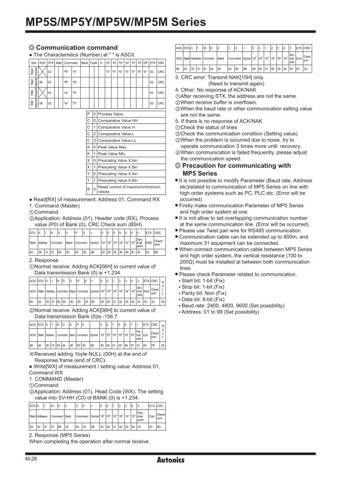
Communication command The Characteristics (Number) at " " is ASCII.
Sort ACK STX Addr Command Bank Code +/- 105 104 103 102 101 100 DP ETX CRC
Read
reque
st
02 "R" "X" "0" "0" "0" "0" "0" "0" "0" 03 CRC
Read
respo
nse
06 02 "R" "D" 03 CRC
Write
resqu
est
02 "w" "X" 03 CRC
Write
respo
nse
06 02 "w" "D" 03 CRC
P 0 Process Value
C 0 Comparative Value HH
C 1 Comparative Value H
C 2 Comparative Value L
C 3 Comparative Value LL
K 0 Peak Value Max.
K 1 Peak Value Min.
X 0 Prescaling Value X.Ain
X 1 Prescaling Value X.Bin
Y 0 Prescaling Value X.Ain
Y 1 Prescaling Value X.Bin
R 0 Reset control of maximum/minimum values
Read[RX] of measurement: Address 01, Command RX1. Command (Master) ①Command ②Application: Address (01), Header code (RX), Process
value (P0) of Bank (0), CRC Check sum (B5H) STX 0 1 R X 0 P 0 + 0 0 0 0 0 0 0 ETX CRC
Start Address Command Bank Command Symbol 105 104 103 102 101 100 Dec-imalpoint
END Checksum
02 30 31 57 58 30 50 30 2B 30 30 30 30 30 30 30 03 B5
2. Response①Normal receive: Adding ACK[06H] to current value of
Data transmission Bank (0) is +1.234.ACK STX 0 1 R D 0 P 0 + 0 0 1 2 3 4 3 ETX CRC N
ULLACK Start Address Command Bank Command Symbol 105 104 103 102 101 100
Dec-imalpoint
End Checksum
06 02 30 31 52 44 30 50 30 2B 30 30 31 32 33 34 33 03 23 00
②Normal receive: Adding ACK[06H] to current value of Data transmission Bank (0)is -156.7.
ACK STX 0 1 R D 0 P 0 - 0 0 1 5 6 7 1 ETX CRC NULLACK Start Address Command Bank Command Symbol 105 104 103 102 101 100
Dec-imalpoint
End Checksum
06 02 30 31 52 44 30 50 30 2D 30 30 31 35 36 37 31 03 75 00
※Received adding 1byte NULL (00H) at the end of Response frame (end of CRC).
Write[WX] of measurement / setting value: Address 01, Command WX1. COMMAND (Master)①Command②Application: Address (01), Head Code (WX), The setting
value into SV-HH (C0) of BANK (0) is +1.234.STX 0 1 W X 0 C 0 + 0 0 1 2 3 4 3 ETX CRC
Start Address Command Bank Command Symbol 105 104 103 102 101 100 Dec-imalpoint
End Checksum
02 30 31 57 58 30 43 30 2B 30 30 31 32 33 34 33 03 5D
2. Response (MP5 Series)When completing the operation after normal receive.
ACK STX 0 1 W D 0 C 0 + 0 0 1 2 3 4 3 ETX CRC
ACK Start Address Command Bank Command Symbol 105 104 103 102 101 100 Dec-imalpoint
End Checksum
06 02 30 31 57 44 30 43 30 2B 30 30 31 32 33 34 33 03 3C
3. CRC error: Transmit NAK[15H] only. (Need to transmit again)
4. Other: No response of ACK/NAK①After receiving STX, the address are not the same.②When receive buffer is overflown.③When the baud rate or other communication setting value
are not the same. 5. If there is no response of ACK/NAK①Check the status of lines②Check the communication condition (Setting value)③When the problem is occurred due to noise, try to
operate communication 3 times more until recovery.④When communication is failed frequently, please adjust
the communication speed. Precaution for communicating withMP5 Series
It is not possible to modify Parameter (Baud rate, Address etc)related to communication of MP5 Series on line with high order systems such as PC, PLC etc. (Error will be occurred)
Firstly make communication Parameter of MP5 Series and high order system at one.
It is not allow to set overlapping communication number at the same communication line. (Error will be occurred)
Please use Twist pair wire for RS485 communication. Communication cable can be extended up to 800m, and maximum 31 equipment can be connected.
When connect communication cable between MP5 Series and high order system, the vertical resistance (100 to 200Ω) must be installed at between both communication lines
Please check Parameter related to communication. Start bit: 1-bit (Fix) Stop bit: 1-bit (Fix) Parity bit: Non (Fix) Data bit: 8-bit (Fix) Baud rate: 2400, 4800, 9600 (Set possibility) Address: 01 to 99 (Set possibility)