mpbx borehole extensometer with groutable anchors … · e10302-20170607 borex 1 1 applications the...
TRANSCRIPT

INSTRUCTION MANUAL
MPBX BOREHOLE EXTENSOMETER WITH GROUTABLE
ANCHORS AND VW SENSORS
Model BOR-EX
Roctest Limited, 2017. All rights reserved.
This product should be installed and operated only by qualified personnel. Its misuse is potentially dangerous. The Company makes no warranty as to the information furnished in this manual and assumes no liability for damages resulting from the installation or use of this product. The information herein is subject to change without notification.
Tel.: 1.450.465.1113 • 1.877.ROCTEST (Canada, USA) • 33 (1) 64.06.40.80 (Europe) • www.roctest.com • www.telemac.fr
E10302-20170607

i
TABLE OF CONTENTS
1 APPLICATIONS ...................................................................................................... 1
2 PRODUCT ............................................................................................................... 1
2.1 General description ........................................................................................... 1
2.1.1 Groutable Anchors ..................................................................................... 2
2.1.2 Connecting rods ......................................................................................... 2
2.1.3 Head assembly .......................................................................................... 2
2.2 Operation principle ............................................................................................ 2
2.3 Important dimensions ........................................................................................ 3
3 INSTALLATION PROCEDURE ............................................................................... 3
3.1 General considerations ..................................................................................... 3
3.1.1 Borehole requirements ............................................................................... 3
3.1.2 Head assembly protection .......................................................................... 3
3.1.3 General installation technique .................................................................... 4
3.2 Tools required ................................................................................................... 4
3.3 Pre-installation acceptance reading................................................................... 4
3.4 Inserting the MPBX into the borehole ................................................................ 5
3.5 Stainless steel rod Assembly procedure ............................................................ 6
3.5.1 Determination of the rod lengths ................................................................ 6
3.5.2 Determination of the protective tube lengths .............................................. 6
3.5.3 Rod assembly ............................................................................................ 6
3.5.4 Final assembly before borehole insertion ................................................... 7
3.6 Borehole grouting .............................................................................................. 8
3.6.1 Downward directed boreholes .................................................................... 8
3.6.2 Upward directed boreholes ........................................................................ 8
3.7 Installation of electrical head assembly ............................................................. 8
3.8 Cable routing and splices ................................................................................ 10
3.9 Initial reading ................................................................................................... 11
4 READING PROCEDURE ....................................................................................... 11
4.1 Displacement readings .................................................................................... 11
4.2 Temperature readings ..................................................................................... 13
4.3 Quick verification of measurements................................................................. 13
5 CONVERSION OF READINGS ............................................................................. 13
5.1 Relative to the reference plate ......................................................................... 13
5.2 Direction of movement .................................................................................... 14
5.3 Effect of temperature ....................................................................................... 15

ii
5.4 Plotting movements ......................................................................................... 15
5.5 Environmental factors ..................................................................................... 15

E10302-20170607 BOREX
1
1 APPLICATIONS
The model BOREX-E extensometer (MPBX) is designed for accurate monitoring of longitudinal displacements in rock masses, concrete, or soil boreholes. Typical applications include monitoring of the following: deformations around tunnels, mines and other underground excavations; settlement of structures; deformation in dams and embankments, etc.
2 PRODUCT
2.1 GENERAL DESCRIPTION
The fiberglass rods model BOREX-E extensometer is comprised of the following:
- Two to six groutable anchors,
- fibreglass rods encased within a protective tubing,
- steel top anchor pipes,
- head assembly which contains vibrating wire displacement transducers
Model BOREX-E extensometer with electrical head and rebar anchors
Multi-Conductors and individual cable gland head configurations

E10302-20170607 BOREX
2
2.1.1 GROUTABLE ANCHORS
Groutable rebar anchors: Easy to install, this type of anchor is used where the borehole can be fully grouted. A good contact between the borehole wall and grout is important to insure that any movements of the rock or soil are transmitted to the anchor.
2.1.2 CONNECTING RODS
The extensometer is assembled at factory, ready to install. The rods are sheathed in plastic tubing to protect them from the injected grout or other confining material.
2.1.3 HEAD ASSEMBLY
The electrical head assembly is mounted directly on the mechanical head that holds the rods. Designed for automatic readings, the head contains the electrical displacement sensors. The head is delivered with the sensors inside of it. These will have to be removed prior to installing the base on the installed extensometer. Numbers are stamped on the reference plate and are used to identify the anchors. The deepest anchor is usually numbered 1. This is the one inserted first into the borehole. The head assembly is fitted with a reference surface, which allows surveying the head if necessary.
Electrical head assembly with vibrating wire sensors
2.2 OPERATION PRINCIPLE
Each anchor is connected to the head of the instrument via extension rods protected within plastic tubing. This tubing ensures that the rods can move freely and translate all anchor movement to the tip of the rod. Movement of the rock or soil mass relative to the head can then be calculated from measuring the displacement of the tip of each extension rod to the reference surface to the extensometer head.
E10302-20170607 BOREX
3
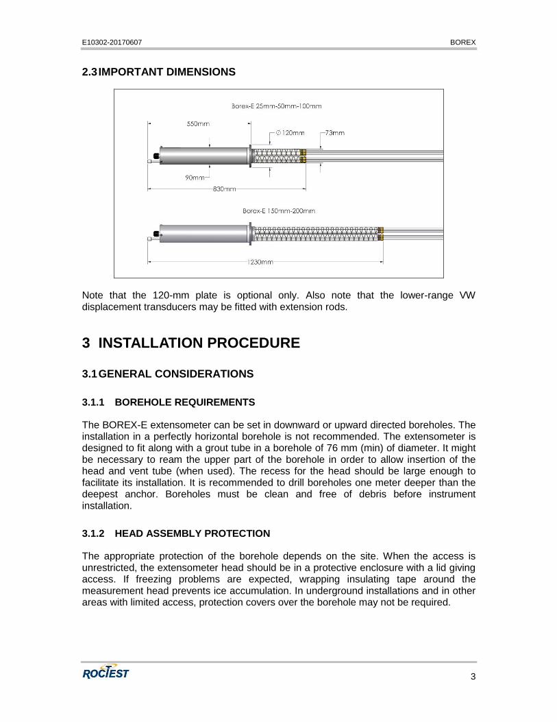
2.3 IMPORTANT DIMENSIONS
Note that the 120-mm plate is optional only. Also note that the lower-range VW displacement transducers may be fitted with extension rods.
3 INSTALLATION PROCEDURE
3.1 GENERAL CONSIDERATIONS
3.1.1 BOREHOLE REQUIREMENTS
The BOREX-E extensometer can be set in downward or upward directed boreholes. The installation in a perfectly horizontal borehole is not recommended. The extensometer is designed to fit along with a grout tube in a borehole of 76 mm (min) of diameter. It might be necessary to ream the upper part of the borehole in order to allow insertion of the head and vent tube (when used). The recess for the head should be large enough to facilitate its installation. It is recommended to drill boreholes one meter deeper than the deepest anchor. Boreholes must be clean and free of debris before instrument installation.
3.1.2 HEAD ASSEMBLY PROTECTION
The appropriate protection of the borehole depends on the site. When the access is unrestricted, the extensometer head should be in a protective enclosure with a lid giving access. If freezing problems are expected, wrapping insulating tape around the measurement head prevents ice accumulation. In underground installations and in other areas with limited access, protection covers over the borehole may not be required.

E10302-20170607 BOREX
4
3.1.3 GENERAL INSTALLATION TECHNIQUE
The extensometer is normally delivered partially assembled – the electrical head is assembled on site after the installation of the lower part of the extensometer in the borehole. The procedure hereafter gives the usual way to install a fiberglass rod extensometer with groutable anchors. It might be adapted to specific site conditions.
3.2 TOOLS REQUIRED
Typically, the following tools will be required for installing a BOREX fitted with groutable anchors:
- ¾-in (max) grout tube
- measuring tape
- sharp knife for cutting grout and vent tubes
- Installation tool to hold the extensometer while inserting it in the borehole
- Special wrench to tighten the sensors fittings
- Wooden wedges
- Electrical tape
- A readout unit
Other potential useful tools
- vent tube for upward installations
- grease for o-rings and moving parts
- wire marker tape
- marking pens
- fast set cement for upward directed boreholes
- spare parts (o-rings, set screws, bolts, screws…)
- nylon rope or steel wire to secure the extensometer when lowering into the borehole
3.3 PRE-INSTALLATION ACCEPTANCE READING
Electrical sensors should be verified as soon as they are received to ensure they have not been damaged during shipment or handling on site. As only differential displacements are taken with a rod extensometer, comparative readings, not absolute, must be taken. The following procedure is suggested:
- Put the sensor on a table and connect it to a readout. Install a graduated tape along it. Hold the left side of the sensor with your left hand and pull the right end

E10302-20170607 BOREX
5
of the sensor with your right hand. Pull the sliding rod about 1 cm and take a reading (position A). Also note position of the sensor’s tip on the graduated tape.
- Pull further away the sliding rod to a second position (point B) towards the end of the range of the sensor. Be sure not to exceed the range of the instrument. Take a second reading and note the value read on the tape.
- Compare relative readings between points A and B. The distance calculated with the gage factors given on the sensors calibration sheet and the distance measured on the tape should be close.
- Repeat with all measuring rods and electrical heads.
3.4 INSERTING THE MPBX INTO THE BOREHOLE
The extensometer is delivered without electrical head. The rod holder is installed and wrapped in factory to avoid the fiber glass rods from extruding from the head while winding the extensometer.
Unwound and lay down the extensometer on the ground.
Use electrical tape to bundle the rod/tubing assemblies together. Start at the head and tape every 2 m. Do note put any tape on the anchors.
The grout tube can then be inserted through the central hole located on top of the extensometer’s mechanical head and attached to the deepest anchor only with masking tape. Do not put too much tape so it will be possible to pull up the grout tube during grouting. Cut three notches near the deepest section of the grout tube.
An optional PVC plate temporary used for sitting the extensometer to the borehole collar can be temporary fixed to the extensometer (see image at right).
Put the installation tool on the extensometer. It is imperative that the installation tool remains in place during grouting. This will keep the rods in place and prevent them from moving until the grout is set.
Installation tool alone and installed
on the extensometer
Insert the extensometer into the borehole at the appropriate position. Precautions must be taken to prevent the extensometer from moving (downward or upward) during grout setting. We recommend using wooden wedges to hold the bundle firmly in place until the grout sets
MPBX with optional plate
ready to be inserted into
the borehole
E10302-20170607 BOREX
6
3.5 STAINLESS STEEL ROD ASSEMBLY PROCEDURE
3.5.1 DETERMINATION OF THE ROD LENGTHS
Stainless steel rods are already prepared in factory before shipment. They come in three meter sections or less and allow the anchors to be placed within thirty centimetres of their desired position. One head rod is also provided on request for better adjustment.
3.5.2 DETERMINATION OF THE PROTECTIVE TUBE LENGTHS
Adjust the protective tube lengths to the rod lengths so that the tubes can be inserted and glued easily into the bulkhead. Please refer to the descriptions of bulkhead sections below.
You have to calculate the last length in accordance with the initial position of the electrical sensor. This position is determined by the anticipated movement. (Full extension, mid-range or full compression).
Be careful to tubing shrinkage.
Avoid large temperature differences between the protective tube and the rods especially during cutting. This occurs when there is an important temperature differential between ambient air and inside the borehole.
Protect the extensometer equipment from the hot sun. If this is impossible, cut longer tubes than necessary, insert anchors, rods and tubes into the borehole, let stabilize and then cut at the desired lengths prior to installing rod reference caps and coupling the tubes to the bulkhead.
3.5.3 ROD ASSEMBLY
With stainless steel rods, proceed as follows.
1. Apply Loctite threaded adhesive to the threads of the lower rod and screw it to the tip of an anchor.
2. Apply Loctite threaded adhesive to the threads of a second rod and then screw it to the tip of the first rod.
3. Slip a section of PVC tube on the rod string. Glue the tube to the coupling near the anchor using PVC primer and PVC cement (glue). The surface must be cleaned and the glue must be applied on the outer tube surface only to avoid the formation of a ridge of glue inside the tube. Allow sufficient time for the glue to set.
4. Continue assembling rods until the proper length is reached. Finish the assembly by the head rod.
5. Slip the protective tubes over the rods and couple them together using PVC couplings. Allow sufficient time for the glue to harden. Last protective tube must
E10302-20170607 BOREX
7
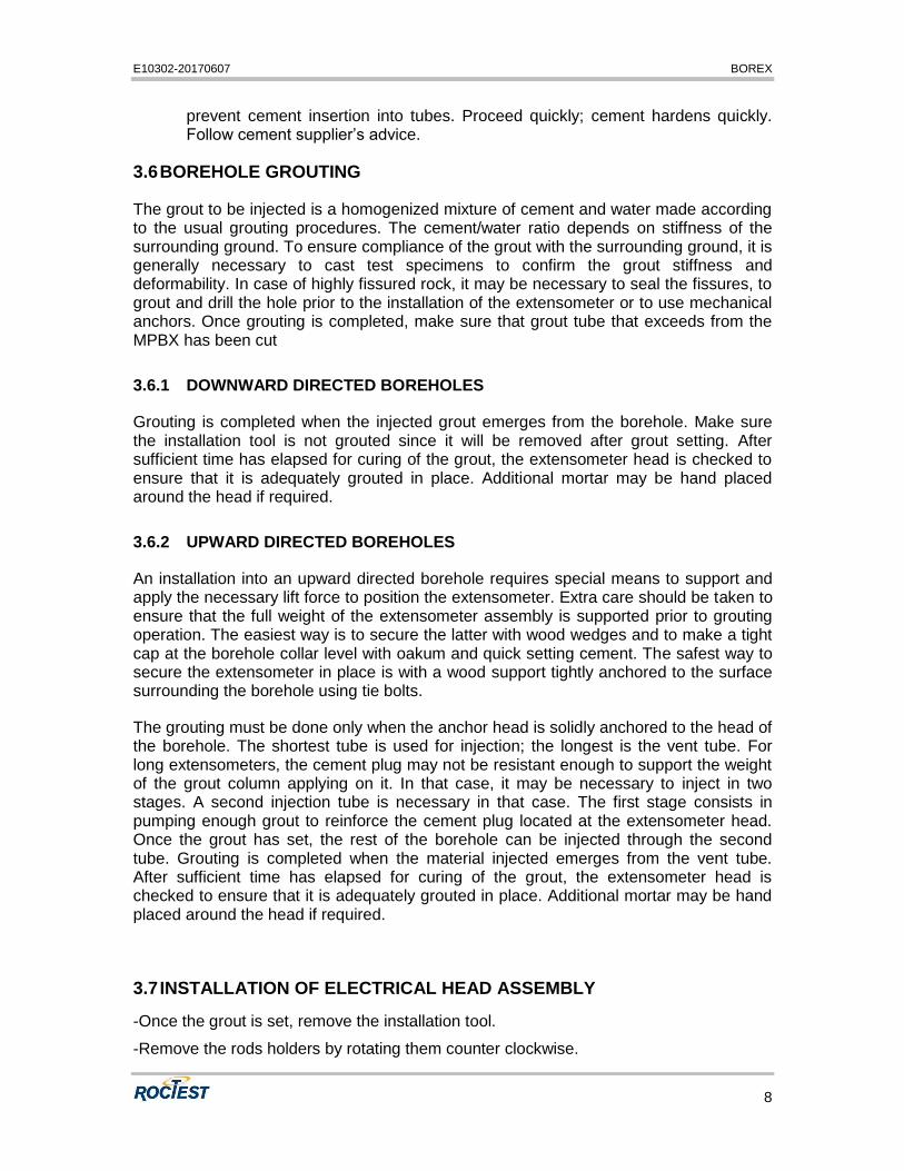
exceed the tip of the last rod. For additional precaution, wrap electrical tape around the couplings.
Anchor and stainless steel rods assembly with protective tube
3.5.4 FINAL ASSEMBLY BEFORE BOREHOLE INSERTION
1. Repeat the above steps until all rods and anchors are assembled. Stagger the coupling joints to minimize the overall diameter of the rod and tube bundle.
2. For an installation into a downward directed borehole, tape the lower end of a grout tube to the lowest anchor. Cut a few lateral openings in the tube to ensure grout passage in the case the end of the grout tube becomes blocked.
For an installation into an upward directed borehole, position a vent tube one meter beyond the deepest anchor and tape it to the assembly. As the end of the vent tube may be bent during installation into the borehole, a small diameter steel bar can be used to make it stiffer. Do not block the grout exit.
3. Tape each anchor to the protective tubes nearby. The grout or vent tube should lie in the center of the bundle. Tape the bundle together at regular intervals.
To avoid tangling or twisting the protective tubes, set all the tubes in a bundle in a fixed angular orientation.
4. Slide the bundle through the anchor pipe.
5. Slide grout and vent tubes throughout the bulkhead.
6. Cut exceeding protective tubes to the proper length.
7. The protective tubes covering the stainless steel rods have to be glued inside the bulkhead. Using PVC primer and cement, start by the longest (position #1) to the shortest. Apply cement only onto tubes (not into bulkhead’s holes) in order to
E10302-20170607 BOREX
8
prevent cement insertion into tubes. Proceed quickly; cement hardens quickly. Follow cement supplier’s advice.
3.6 BOREHOLE GROUTING
The grout to be injected is a homogenized mixture of cement and water made according to the usual grouting procedures. The cement/water ratio depends on stiffness of the surrounding ground. To ensure compliance of the grout with the surrounding ground, it is generally necessary to cast test specimens to confirm the grout stiffness and deformability. In case of highly fissured rock, it may be necessary to seal the fissures, to grout and drill the hole prior to the installation of the extensometer or to use mechanical anchors. Once grouting is completed, make sure that grout tube that exceeds from the MPBX has been cut
3.6.1 DOWNWARD DIRECTED BOREHOLES
Grouting is completed when the injected grout emerges from the borehole. Make sure the installation tool is not grouted since it will be removed after grout setting. After sufficient time has elapsed for curing of the grout, the extensometer head is checked to ensure that it is adequately grouted in place. Additional mortar may be hand placed around the head if required.
3.6.2 UPWARD DIRECTED BOREHOLES
An installation into an upward directed borehole requires special means to support and apply the necessary lift force to position the extensometer. Extra care should be taken to ensure that the full weight of the extensometer assembly is supported prior to grouting operation. The easiest way is to secure the latter with wood wedges and to make a tight cap at the borehole collar level with oakum and quick setting cement. The safest way to secure the extensometer in place is with a wood support tightly anchored to the surface surrounding the borehole using tie bolts.
The grouting must be done only when the anchor head is solidly anchored to the head of the borehole. The shortest tube is used for injection; the longest is the vent tube. For long extensometers, the cement plug may not be resistant enough to support the weight of the grout column applying on it. In that case, it may be necessary to inject in two stages. A second injection tube is necessary in that case. The first stage consists in pumping enough grout to reinforce the cement plug located at the extensometer head. Once the grout has set, the rest of the borehole can be injected through the second tube. Grouting is completed when the material injected emerges from the vent tube. After sufficient time has elapsed for curing of the grout, the extensometer head is checked to ensure that it is adequately grouted in place. Additional mortar may be hand placed around the head if required.
3.7 INSTALLATION OF ELECTRICAL HEAD ASSEMBLY
-Once the grout is set, remove the installation tool.
-Remove the rods holders by rotating them counter clockwise.

E10302-20170607 BOREX
9
-Remove the sensors from the holding fittings in the electrical head.
-Install the base of the electrical head on the mechanical extensometers head and make sure that holes are aligned.
IMPORTANT NOTE: The threaded base of the electrical head and its mating extensometer mechanical head are fitted together in order to align the rods positions. They are marked in pairs. Do not mix different components with others.
-Insert the first sensor at proper position according to the sheet provided by Roctest indicacting position of each sensor. Thread the sensor completely onto the MPBX corresponding rod.
-Connect sensor wires to a readout unit.
- Gently pull the sensor to the desired initial position (typically at mid-range). BE CAREFULL NOT TO ROTATE THE SENSOR WHILE PULLING ON IT. SEVERE DAMAGE MAY OCCUR TO THE SENSORS.
-Using the special long wrench, gently tighten the brass fitting to lock the sensors in place.
E10302-20170607 BOREX
10
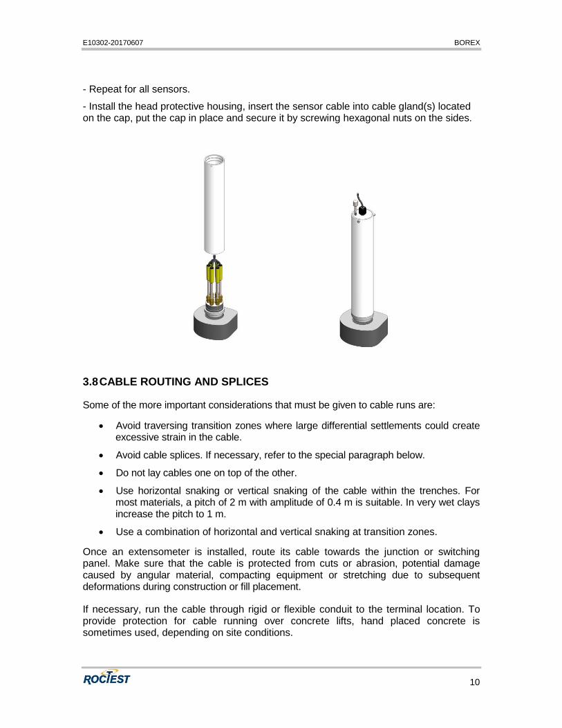
- Repeat for all sensors.
- Install the head protective housing, insert the sensor cable into cable gland(s) located on the cap, put the cap in place and secure it by screwing hexagonal nuts on the sides.
3.8 CABLE ROUTING AND SPLICES
Some of the more important considerations that must be given to cable runs are:
Avoid traversing transition zones where large differential settlements could create excessive strain in the cable.
Avoid cable splices. If necessary, refer to the special paragraph below.
Do not lay cables one on top of the other.
Use horizontal snaking or vertical snaking of the cable within the trenches. For most materials, a pitch of 2 m with amplitude of 0.4 m is suitable. In very wet clays increase the pitch to 1 m.
Use a combination of horizontal and vertical snaking at transition zones.
Once an extensometer is installed, route its cable towards the junction or switching panel. Make sure that the cable is protected from cuts or abrasion, potential damage caused by angular material, compacting equipment or stretching due to subsequent deformations during construction or fill placement.
If necessary, run the cable through rigid or flexible conduit to the terminal location. To provide protection for cable running over concrete lifts, hand placed concrete is sometimes used, depending on site conditions.

E10302-20170607 BOREX
11
Check that the cable does not cross over itself or other cables in the same area. Surface installations require continuous surveillance and protection from the earth moving equipment circulating on the field. During the cable routing, read the instruments at regular intervals to ensure continued proper functioning. Record the cable routing with care and transfer this routing to the drawings.
Generally, cable splices are to be avoided. If necessary, use only the manufacturer’s approved standard or high-pressure splice kit. Splicing instructions are included with the splice kit. Should the cable be cut, we recommend the use of our high pressure cable splice kits, especially if the splice is located underwater. In special cases on site (large distance between sensors, chain of instruments, readout position for example), splices are useful to limit the number of cables to lay. Actually, individual instrument cables can be merged into a multi-conductor cable using a splice or a junction box.
Please contact us for additional information about junction boxes and splice kits. At all times during the installation, any cable that is exposed to potential damage by lightning must be protected.
3.9 INITIAL READING
Readings taken after definitive installation of the head assembly are considered as initial readings. Calculate them in millimetres. All subsequent readings are referenced to initial readings. Therefore, those measurements have to be the most accurate as possible.
4 READING PROCEDURE
4.1 DISPLACEMENT READINGS
Readings are taken manually with a portable readout unit model – with an MB-3TL or MB-6T(L) readout - or automatically when connected to a SENSLOG DAS.
The readout unit with the four-pin, male, panel-mounted electrical connector is supplied with one multi-core cable fitted with a mating female connector at one end and a set of four color coded alligator clips at the other. The conductor’s insulation is color coded to match that of the alligator clips and the cable conductors’ insulation jacket of standard vibrating wire instruments. The alligator clips of the readout unit should be connected to the gage lead wire according to the table below. Please refer to the calibration sheets supplied with the sensors for the wiring code.
Connections
Cable Wire High Wire Low Temp. High Temp. Low / Shield
IRC-41A(P) Red black white green shield
Wiring code for electrical cables

E10302-20170607 BOREX
12
To obtain a reading, set readout to HZ2 + THERMISTOR when using an MB-3TL, or to POSITION 2 (JM) and the Thermistor selector to POSITION B (3K) when using an MB-6T(L).
PLEASE REFER TO THE INSTRUCTION MANUAL OF THE MB-3TL OR MB-6T(L) FOR MORE DETAILS ABOUT READING PROCEDURE
The jumper cables should never be short-circuited when they are connected to the readout unit front panel.
For the absolute measurement of the displacement, the following equation applies using LINEAR units displayed by the MB-3TL or MB-6T(L):
CLBLAD 2
where D = displacement in millimetres
A, B, C = calibration factors (see calibration sheet)
L = reading in LINEAR units (LU)
Example: (please refer to calibration sheet in appendix)
With L = 6 000 LU
A = 4.3623E-08 mm/LU2
B = 1.6502E-02 mm/LU
C = -3.1458E+01 mm
We get: D = 69.12 mm
Increasing readings in LINEAR units indicate increasing displacement.
If the frequency is measured, convert it into LINEAR units using the following equation:
1000
2FKL
where L = reading in LINEAR units
K = gage constant for displacement sensors = 1.0000
F = frequency in Hz
Example:
E10302-20170607 BOREX
13
With F = 2 449 Hz,
We get: 1000
244901
2
.L 5 997.6 LU
4.2 TEMPERATURE READINGS
Although the readout boxes give directly the correct value of temperature (in °C), the temperature can also be read with an ohmmeter. To convert the resistance value into temperature reading, please refer to the instruction manual of the TH-T gage.
4.3 QUICK VERIFICATION OF MEASUREMENTS
On site, even before analysing data, several checks can be done to prevent a bad measurement.
- Compare readings to previous ones. Are they in the same range? Are they moving slowly or abruptly? Consider external factors that can affect the measurements like construction activities, excavations or fills…
- In any case, it is advised to take several readings to confirm the measurement. Then, repeatability can be appreciated and dummy readings erased.
5 CONVERSION OF READINGS
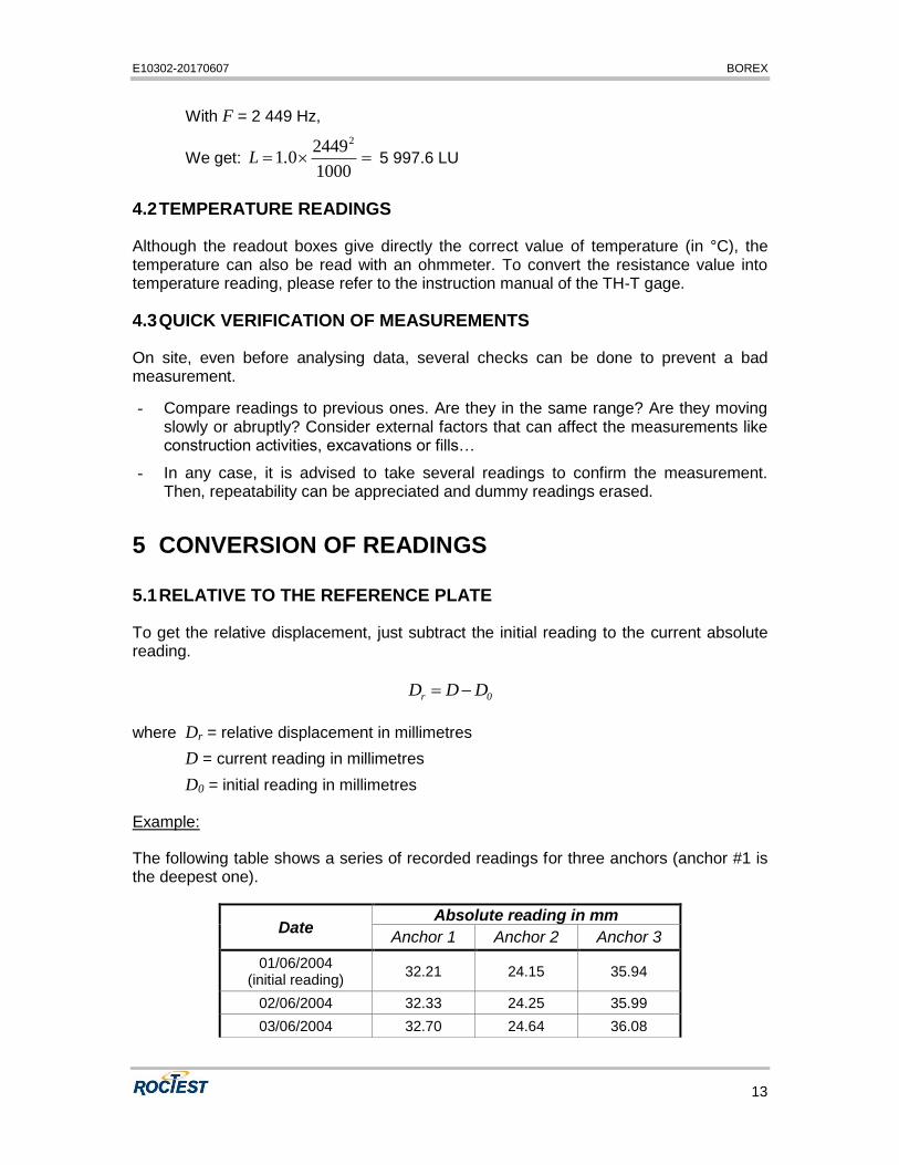
5.1 RELATIVE TO THE REFERENCE PLATE
To get the relative displacement, just subtract the initial reading to the current absolute reading.
0r DDD
where Dr = relative displacement in millimetres
D = current reading in millimetres
D0 = initial reading in millimetres
Example:
The following table shows a series of recorded readings for three anchors (anchor #1 is the deepest one).
Date Absolute reading in mm
Anchor 1 Anchor 2 Anchor 3
01/06/2004 (initial reading)
32.21 24.15 35.94
02/06/2004 32.33 24.25 35.99
03/06/2004 32.70 24.64 36.08

E10302-20170607 BOREX
14
04/06/2004 33.11 24.84 36.22
05/06/2004 34.00 25.57 36.64
07/06/2004 35.09 26.45 36.94
09/06/2004 35.96 27.08 37.25
10/06/2004 36.38 27.45 37.38
11/06/2004 36.60 27.66 37.49
12/06/2004 36.58 27.71 37.30
Absolute readings
To calculate the movement of each anchor, subtract the initial reading from each of subsequent readings. The following table shows the results.
Date Relative movement in mm
Anchor 1 Anchor 2 Anchor 3
01/06/2004 (initial reading)
0.00 0.00 0.00
02/06/2004 0.12 0.10 0.05
03/06/2004 0.49 0.49 0.14
04/06/2004 0.90 0.69 0.28
05/06/2004 1.79 1.42 0.70
07/06/2004 2.88 2.30 1.00
09/06/2004 3.75 2.93 1.31
10/06/2004 4.17 3.30 1.44
11/06/2004 4.39 3.51 1.55
12/06/2004 4.37 3.56 1.36
Relative movements
It is advisable to optically survey the possible vertical movements of the reference head for a better comprehension of soil movements.
5.2 DIRECTION OF MOVEMENT
The direction of movement is determined as follows:
WHEN RELATIVE MOVEMENT IS POSITIVE, THE DISTANCE BETWEEN THE REFERENCE HEAD AND THE ANCHOR IS …
Vibrating wire sensor INCREASING (EXTENSION)
Relative movement sign vs. Direction of movement

E10302-20170607 BOREX
15
5.3 EFFECT OF TEMPERATURE
Effect of temperature on the vibrating wire sensor is relatively low and is often not considered. However, when large temperature variations are expected (over 10 degrees Celsius) and when maximum accuracy is desired, temperature corrections can be done. Each vibrating wire displacement transducer is fitted with a 3 k ohms thermistor. Individual correction factors can then be determined at our factory upon request. Also, if significant temperature variations are expected in the ground, temperature sensors can be installed along the rods.
5.4 PLOTTING MOVEMENTS
A common representation of extensometer readings is to plot the movements of each anchor against time to visualize the deformations and to evaluate their velocity. An example of plot follows.
-5.0
-4.0
-3.0
-2.0
-1.0
0.0
01/06/2004 03/06/2004 05/06/2004 07/06/2004 09/06/2004 11/06/2004
Mo
vem
en
t in
mm
Ref plate Anchor 2 Anchor 3
Example of extensometer plot
Another representation consists in plotting the variations of the spacing between two following anchors. This can help to detect local settlements and week zones of soil.
5.5 ENVIRONMENTAL FACTORS
Since the purpose of the extensometer installation is to monitor site conditions, factors which may affect these conditions should always be observed and recorded. Seemingly minor effects may have a real influence on the behaviour of the structure being monitored and may give an early indication of potential problems. Some of these factors include, but are not limited to: blasting, rainfall, tidal levels, excavation and fill levels and sequences, traffic, temperature and barometric changes, changes in personnel, nearby construction activities, seasonal changes, etc.
Anchor 1

E10302-20170607 BOREX
16
APPENDIX 1
EXAMPLE OF CALIBRATION SHEET