mpc system - 120 vac
TRANSCRIPT

www.cet-power.com Belgium, China, India, Luxembourg, Malaysia, Russia, Turkey, United Kingdom, United States, Australia & Germany
Copyright © 2013. Construction electroniques & telecommunications S.A. All rights reserved. The contents in document are subject to change without notice.The products presented are protected by several international patents and trademarks.Address: CE+T S.a, Rue du Charbonnage 12, B 4020 Wandre, Belgiumwww.cet-power.com - [email protected]
• DUAL INPUT INVERTERCommercial Power as default source
• AC BACKUP IN A DC ENVIRONMENTLeverage your existing DC infrastructure
• ONE STOP SHOP Wide output power range
• HARSHEST AC INPUT CONDITIONSWithout compromising the quality of the AC output
BEYOND THE INVERTER THE NEW GENERATION OF POWER CONVERTERS
MPC SYSTEM - 120 VAC MEDIA POWER CENTER
User Manual V7.5

2 – MPC System – 120 Vac – User manual – v7.5
Table of content1. CE+T at a glance ................................................................................................................................... 6
2. Abbreviations ........................................................................................................................................ 7
3. Warranty and Safety Conditions ............................................................................................................. 83.1 Disclaimer ................................................................................................................................... 83.2 Technical care ............................................................................................................................. 83.3 Installation .................................................................................................................................. 9
3.3.1 Handling ......................................................................................................................... 93.3.2 Surge and transients ...................................................................................................... 103.3.3 Other .............................................................................................................................. 10
3.4 Maintenance .............................................................................................................................. 103.5 Replacement and Dismantling ..................................................................................................... 10
4. TSI TECHNOLOGY .................................................................................................................................. 114.1 EPC Mode ................................................................................................................................... 124.2 On-line Mode .............................................................................................................................. 124.3 Safe Mode ................................................................................................................................... 124.4 Mix Mode & Walk-in Mode ........................................................................................................... 12
5. Inverter Module ...................................................................................................................................... 135.1 Media .......................................................................................................................................... 13
6. Accessories ........................................................................................................................................... 146.1 T2S Interface ............................................................................................................................... 14
6.1.1 Parameters setting ......................................................................................................... 146.1.2 System diagnostic and troubleshooting ......................................................................... 146.1.3 Section Monitoring ......................................................................................................... 14
6.2 Catena ........................................................................................................................................ 156.3 Candis ......................................................................................................................................... 166.4 Manual By-Pass .......................................................................................................................... 16
7. MPC Design and Description .................................................................................................................. 177.1 System Design ............................................................................................................................ 177.2 System Description ..................................................................................................................... 187.3 MPC Single Phase Configuration - 120 VAC ................................................................................. 197.4 MPC Single Phase Configuration - 240 VAC ................................................................................. 207.5 MPC Three Phase Configuration - 208 VAC .................................................................................. 217.6 MPC Module based Current Ratings ............................................................................................ 22
8. System Installation ................................................................................................................................. 238.1 Site Preparation ........................................................................................................................... 23
8.1.1 Transformer and Generator Sizing .................................................................................. 248.2 Packing Information .................................................................................................................... 248.3 Rack Installation of the MPC ........................................................................................................ 248.4 Cabling ........................................................................................................................................ 25
3 – MPC System – 120 Vac – User manual – v7.5
8.4.1 Conduit Entry ................................................................................................................. 258.4.2 Cabinet Grounding .......................................................................................................... 258.4.3 AC Input and Output ....................................................................................................... 268.4.4 DC Input Terminal Connection ......................................................................................... 298.4.5 Customer Field Connections ........................................................................................... 33
9. Human-Machine Interface ...................................................................................................................... 359.1 Inverter module ........................................................................................................................... 359.2 T2S ............................................................................................................................................. 359.3 Candis Interface .......................................................................................................................... 36
9.3.1 Installing Candis Display ................................................................................................. 369.3.2 Replacing Candis Display ............................................................................................... 38
9.4 Catena GUI Interface .................................................................................................................... 399.4.1 Installing Catena GUI Interface ........................................................................................ 399.4.2 Replacing the Catena GUI Interface ................................................................................. 40
10. System set up ....................................................................................................................................... 4210.1 T2S USB ...................................................................................................................................... 42
10.1.1 Communication Setting .................................................................................................. 4210.1.2 Menu access .................................................................................................................. 43
10.2 T2S Ethernet via Catena .............................................................................................................. 4410.2.1 User GUI Interface Catena ............................................................................................... 4410.2.2 The TOOLBAR ................................................................................................................. 50
10.3 Switching OFF MPC System ........................................................................................................ 52
11. Inserting/removing/replacing modules ................................................................................................... 5311.1 TSI Inverter Module ..................................................................................................................... 53
11.1.1 Removal ......................................................................................................................... 5311.1.2 Inserting ......................................................................................................................... 53
11.2 T2S ............................................................................................................................................. 5411.2.1 Removal ......................................................................................................................... 5411.2.2 Inserting ......................................................................................................................... 54
11.3 Fan replacement ......................................................................................................................... 54
12. Manual By-Pass Operation ..................................................................................................................... 5512.1 Pre requisites .............................................................................................................................. 5512.2 Manual By-Pass Operation ......................................................................................................... 55
12.2.1 Normal to By-Pass, Engage MBP .................................................................................... 5612.2.2 By-Pass to Normal, Disengage MBP ............................................................................... 56
13. Final Check ............................................................................................................................................ 57
14. Installation & Commissioning of TSI Systems ......................................................................................... 5814.1 Installation Check List ................................................................................................................. 5914.2 Alarm Test ................................................................................................................................... 6414.3 Maintenance Bypass Switch (MBP) Test ....................................................................................... 65
15. Troubleshooting ..................................................................................................................................... 6715.1 Trouble Shooting ......................................................................................................................... 67

4 – MPC System – 120 Vac – User manual – v7.5
15.2 Defective modules ....................................................................................................................... 6815.2.1 Replacing modules ......................................................................................................... 6815.2.2 Return defective T2S interface ....................................................................................... 6815.2.3 Return defective shelf .................................................................................................... 6815.2.4 Return defective modules ............................................................................................... 68
16. Service ................................................................................................................................................. 69
17. Preventive Maintenance ........................................................................................................................ 70

Release Note:
VersionRelease date
(DD/MM/YYYY)Modified page
numberModifications
7.0 7/11/2014 - First release of the Manual.
7.1 19/03/2015 - Amendment and correction.
7.2 15/02/2016 - Amendment and correction.
7.3 14/11/2017 - Amendment and correction.
7.4 1/08/2018 19 - 21 Updated table values.
7.5 24/01/2020 - Amendment and correction.
5 – MPC System – 120 Vac – User manual – v7.5

1. CE+T at a glanceCE+T Power designs, manufactures and markets a range of products for industrial operators with mission critical applications, who are not satisfied with existing AC backup systems performances, and related maintenance costs.
Our product is an innovative AC backup solution that unlike most used UPS’s
• Maximizes the operator’s applications uptime;
• Operates with lowest OPEX;
• Provides best protection to power disturbances;
• Optimizes footprint.
Our systems are:
• Modular
• Truly redundant
• Highly efficient
• Maintenance free
• Battery friendly
CE+T power puts 60+ years expertise in power conversion together with worldwide presence to provide customized solutions and extended service 24/7 - 365 days per year.
6 – MPC System – 120 Vac – User manual – v7.5
CE+T at a glance
2. Abbreviations TSI Twin Sine Innovation
EPC Enhanced Power Conversion
REG Regular
DSP Digital Signal Processor
AC Alternating current
DC Direct current
ESD Electro Static Discharge
MET Main Earth Terminal
MBP Manual Bypass
TCP/IP Transmission Control Protocol/Internet Protocol
USB Universal Serial Bus
PE Protective Earth (also called Ground Conductor / GND)
N Neutral
PCB Printed Circuit Board
TRS True Redundant Structure
MCB Miniature Circuit Breaker
MCCB Molded Case Circuit Breaker
CB Circuit Breaker
7 – MPC System – 120 Vac – User manual – v7.5
Abbreviations

3. Warranty and Safety Conditions*
WARNING:
The electronics in the power supply system are designed for an indoor, clean environment.
When installed in a dusty and/or corrosive environment, indoor, it is important to:
• Install an appropriate filter on the enclosure door, or on the room’s air conditioning system.
• Keep the enclosure door closed during operation.
• Replace the filters on a regular basis.
Important Safety Instructions, Save These Instructions.
3.1 Disclaimer • The manufacturer declines all responsibilities if equipment is not installed, used or operated according to the
instructions herein by skilled technicians according to local regulations.
• Warranty does not apply if the product is not installed, used or handled according to the instructions in the manual.
• This equipment is shipped with a SHOCKWATCH monitor. If the SHOCKWATCH shows that the equipment was exposed to excessive force the warranty will be void.
3.2 Technical care • This electric equipment can only be repaired or maintained by a “qualified employee” with adequate training.
Even personnel who are in charge of simple repairs or maintenance are required to have knowledge or experience related to electrical maintenance.
• Please follow the procedures contained in this Manual, and note all the “DANGER”, “WARNING” AND “NOTICE” marks contained in this Manual. Warning labels must not be removed.
• Qualified employees are trained to recognize and avoid any dangers that might be present when working on or near exposed electrical parts.
• Qualified employees know how to lock out and tag out machines so the machines will not accidentally be turned on and injure employees working on them.
• Qualified employees also know safety related work practices, including those by OSHA and NFPA, as well as knowing what personal protective equipment should be worn.
• All operators are to be trained to perform the emergency shut-down procedure.
• Never wear metallic objects such as rings, watches, or bracelets during installation, service and maintenance of the product.
• Maximum operating ambient temperature is 40°C (104°F).
• Insulated tools must be used at all times when working with live systems.
• When handling the system/units pay attention to sharp edges.
• This product is suitable for use in a computer room.
* These instructions are valid for most CE+T Products/Systems. Some points might however not be valid for the product described in this manual.
8 – MPC System – 120 Vac – User manual – v7.5
Warranty and Safety Conditions

3.3 Installation • This product is intended to be installed only in restricted access areas as defined by UL60950 and in accordance
with the National Electric Code, ANSI/NFPA 70, or equivalent agencies.
• The Inverter System may contain output over current protection in the form of circuit breakers. In addition to these circuit breakers, the user must observe the recommended UL listed upstream and downstream circuit breaker requirements as defined in this manual.
• Please use extreme caution when accessing circuits that may be at hazardous voltages or energy levels.
• The modular inverter rack is a dual input power supply. The complete system shall be wired in a way that both input and output leads can be de-energized when necessary.
• REG systems and EPC systems that have no AC input wired and connected can be seen as independent power sources. To comply with local and international safety standards N (input) and PE shall be bonded. The bonded connection between N (input) and PE must be removed once the AC input is connected, Refer 8.4.3, page 26.
• AC and DC circuits shall be terminated with no voltage / power applied (de-energized).
• The safety standard IEC/EN62040-1-1 requires that, in the event of an output short circuit, the inverter must disconnect in 5 seconds maximum. The parameter can be adjusted on T2S ETH; however, if the parameter is set at a value > 5 seconds, an external protection must be provided so that the short circuit protection operates within 5 seconds. Default setting is 60 seconds.
• The system is designed for installation within an IP20 environment. When installed in a dusty or humid environment, appropriate measures (air filtering) must be taken.
• All illustrations in the manual are for general reference, refer to the technical drawing which is received along with the system for exact information.
• Environment Conditions:
� Storage Conditions: -40 to 70°C
� Relative Humidity: 95%, non-condensing
� Altitude above sea without de-rating: Less than 1500 m Greater than 1500 m – de-rating at 0.8% per 100 m
3.3.1 Handling
• The cabinet shall not be lifted using lifting eyes.
• Remove weight from the cabinet by unplugging the inverters. Mark inverters clearly with shelf and position for correct rebuild. This is especially important in dual or three phase configurations.
• Empty inverter positions must not be left open. Replace with module or cover.
• This equipment is shipped with a SHOCKWATCH monitor. If the SHOCKWATCH shows that the equipment was exposed to excessive force the warranty will be void.
9 – MPC System – 120 Vac – User manual – v7.5
Warranty and Safety Conditions
3.3.2 Surge and transients
The mains (AC) supply of the modular inverter system shall be fitted with Lightning surge suppression and Transient voltage surge suppression suitable for the application at hand. Manufacturer’s recommendations of installation shall be adhered to. Selecting a device with an alarm relay for function failure is advised.
Indoor sites are considered to have a working lightning surge suppression device in service.
• Indoor sites Min Class II.
• Outdoor sites Min Class I + Class II or combined Class I+II. The modular inverter system/rack can reach hazardous leakage currents. Grounding must be carried out prior to energizing the system. Grounding shall be made according to local regulations.
3.3.3 Other
• Insulation test (Hi-Pot) must not be performed without instructions from the manufacturer.
3.4 Maintenance • The modular inverter system/rack can reach hazardous leakage currents. Grounding must be carried out prior to
energizing the system. Grounding shall be made according to local regulations.
• Prior to any work conducted on a system/unit make sure that AC input voltage and DC input voltage are disconnected.
• Inverter modules and shelves contain capacitors for filtering and energy storage. Prior to accessing the system/modules after power down, wait at least 5 minutes to allow capacitors to discharge.
• Some components and terminals carry high voltage during operation. Contact may result in fatal injury.
3.5 Replacement and Dismantling • ESD Strap must be worn when handling PCB’s and open units.
• CE+T cannot be held responsible for disposal of the Inverter system and therefore the customer must segregate and dispose of the materials which are potentially harmful to the environment, in accordance with the local regulations in force in the country of installation.
• If the equipment is dismantled, to dispose of its component products, you must comply with the local regulations in force in the country of destination and in any case avoid causing any kind of pollution.
To download the latest documentation and software, please visit our website at www.cet-power.com
10 – MPC System – 120 Vac – User manual – v7.5
Warranty and Safety Conditions

11 – MPC System – 120 Vac – User manual – v7.5
TSI TECHNOLOGY
4. TSI TECHNOLOGY 1
Inverter modules carrying the TSI logo and the EPC mark are triple port converters (AC in, DC in, AC out). Sinusoidal AC output is converted from the AC main source and/or the DC source.
The block diagram below gives an explicit description of the topology and operation.
BOOST
DSP
T2S
EMIFILTER
EMIFILTER
EMIFILTER
UserInterface
RedundantCommuication
Bus
L
N
L’
N’
-
+
Local Signaling
The module is built around the following sub-converters
• AC to DC at input
• DC to DC at input
• DC to AC at output
The energy can flow either from the AC source or the DC source under the control of the local DSP controller. The output sine wave is constant and disturbance free regardless of the active source due to internal energy buffering,
The BOOST functionality multiplies the nominal current by 10 for a period of 20 ms (max) in the event of downstream current surge or fault. The upstream breakers do not have to be oversized to prevent tripping. After the boost has been activated or if the AC input is not present the overload capacity is 150% for 15 seconds regardless of the source currently used.
The TSI works according to True Redundant Structure (TRS) that features decentralized and independent logic, redundant communication bus and three internal levels of disconnection to isolate a module after internal failure.
The TRS functionality is included in every inverter module. Running them in parallel provides a modular system with no single point of failure, 100% pure sinusoidal output, high system efficiency, and 0 ms source transfer time.
.
1 Information and data given in this chapter intend to for an overview on the technology. Detailed features and parameters for each individual module type of the range may differ and should be referred in the dedicated data sheet.

12 – MPC System – 120 Vac – User manual – v7.5
TSI TECHNOLOGY
4.1 EPC Mode • In EPC mode, the AC Main source is the primary source while the DC source is secondary.
• The TSI is designed to operate on the AC main source on a permanent basis and to deliver output AC voltage with low THD.
• There is no physical difference on the output sine wave whether the source is AC (or) DC. If the AC main source is out of tolerance or drops below acceptable level, the converter seamlessly switches to DC and the converter operates in “Back-up mode” (Transfer time is 0 ms).
• As soon as the AC main source returns to its normal operating range, the EPC mode is automatically resumed.
• The EPC mode offers higher efficiency (up to 96% depending on the model) without compromising the purity of the sine wave output.
4.2 On-line Mode • In On-line Mode, the DC source is the primary source of supply while the AC main source works as the
secondary source of supply. Switching time between DC input and AC input is 0ms (source transfer).
• The power delivered by the DC source (usually a battery but it could be any other type of DC generator) is converted to provide regulated and transient free AC power to the load.
• In case of short circuit at the load side, the boost is automatically energized for a specific duration to trip downstream protective devices.
4.3 Safe Mode • Safe mode uses the DC source as primary source of supply while the AC main source is in secondary standby.
• The AC main source is normally disconnected through an internal relay and is only connected when down stream fault clearance is required (boost) or if the DC source is unavailable.
• The transfer time between DC and AC results in a typical transfer time of 10 ms.
• Safe mode is used in extremely harsh environments such as railways. Under harsh conditions it provides extra isolation against disturbances carried by the AC main source.
4.4 Mix Mode & Walk-in Mode • Under certain circumstances the DC and AC source can be combined. The sequence is defined by a user
selectable set of parameters. Start, control and exit functions are fully automatic.
• A specific example of Mix-mode is the Walk-in mode where the transfer from DC source to AC source is ramped up within a fix and adjustable period of time.
• Setting for Walk-in mode and Mix-mode can be made through the T2S supervisor configuration file. See Section 10, page 42 for more information on T2S supervisor.
Note: REG modules
Inverter modules carrying the TSI logo together with REG mark are modules working only with DC input. Sinusoidal output is converted from DC and the module operates as a traditional inverter. EPC mode and the boost are not available with REG modules.

13 – MPC System – 120 Vac – User manual – v7.5
Inverter Module
5. Inverter Module
5.1 MediaTelecom / Datacom: -48 VDC / 120 VAC / 230 VAC, 60 Hz.
• The TSI Media module is a 1500 VA / 1200 W triple port inverter.
• The TSI inverter modules are hot swappable and hot pluggable.
• The module LEDs indicate converter status and output power.
• Fan is equipped with alarm and run time meter. The fan is field replaceable.
• 10.2” (D) x 4” (W) x 3.4” (H)
• 2.4 Kg (5.3 lbs). Figure 1. TSI Media Module

6. Accessories
6.1 T2S InterfaceThe T2S interface provides operator access to the configuration and setup files of the TSI modules that are connected together in any TSI system.
The T2S doesn’t perform any control or management of the TSI system. It can be removed, replaced or moved to another live system without affecting either system.
6.1.1 Parameters setting
The T2S interface is featured with a USB connector or a Ethernet port at the front, it enables TSI system settings, module phase assignments, and other parameter settings to provide the best fit for site conditions.
6.1.2 System diagnostic and troubleshooting
The T2S is featured with a built-in user interface to allow on-line diagnostics using a laptop.
Installers and maintenance technicians should always carry proper laptop software and communication drivers to access / reconfigure the system on site.
6.1.3 Section Monitoring
The T2S USB and T2S ETH monitors a maximum of 32 inverter modules.
The T2S USB and T2S ETH is featured with
• 3 outgoing alarm contacts.
• 2 digital inputs.
• MOD bus.
• CAN bus (optional).
• Alarm monitoring.
• Recording of the events as FIFO
� T2S USB - 200 Events
� T2S ETH - 2000 Events
Note: Operation of the T2S is described in a separate manual available on request.
Figure 2. Monitoring - T2S USB / ETH
14 – MPC System – 120 Vac – User manual – v7.5
Accessories
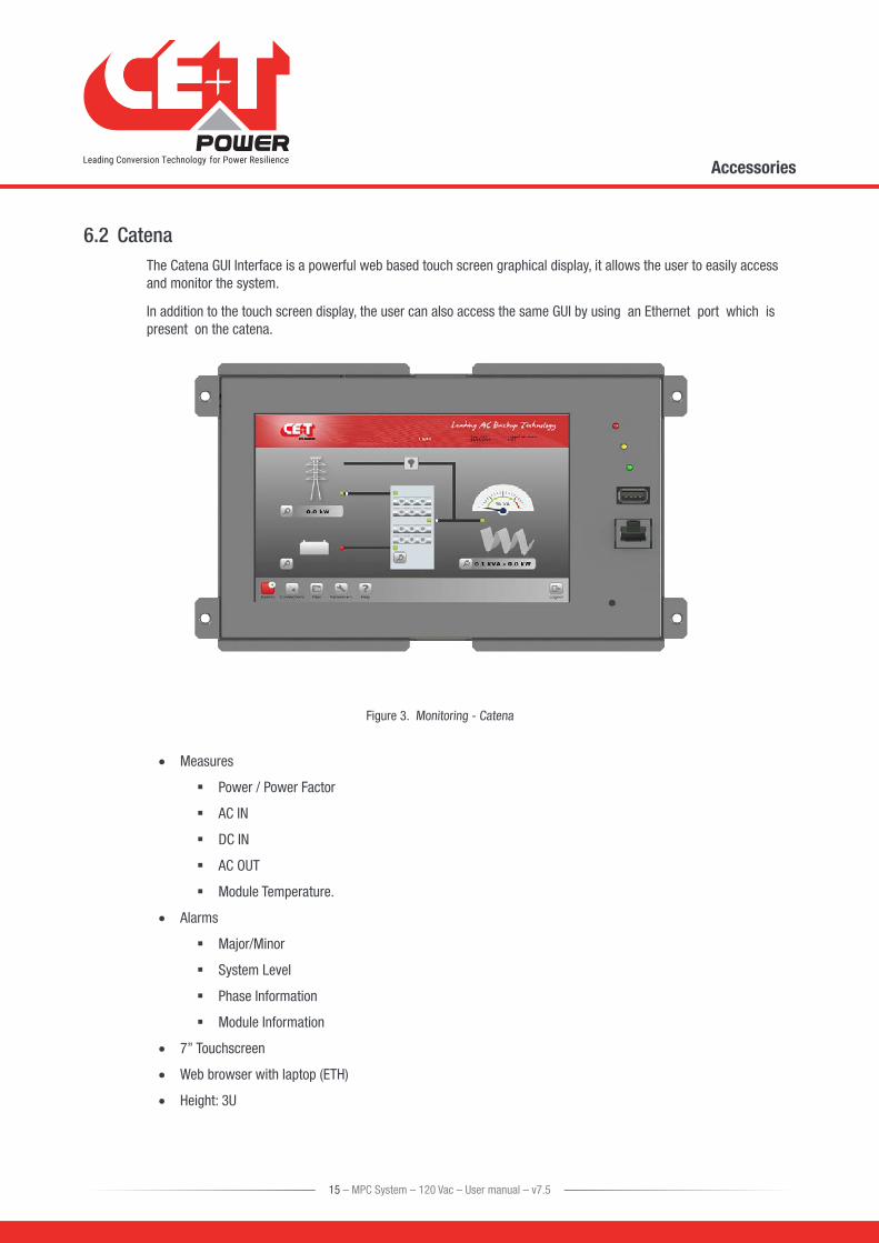
6.2 CatenaThe Catena GUI Interface is a powerful web based touch screen graphical display, it allows the user to easily access and monitor the system.
In addition to the touch screen display, the user can also access the same GUI by using an Ethernet port which is present on the catena.
Figure 3. Monitoring - Catena
• Measures
� Power / Power Factor
� AC IN
� DC IN
� AC OUT
� Module Temperature.
• Alarms
� Major/Minor
� System Level
� Phase Information
� Module Information
• 7’’ Touchscreen
• Web browser with laptop (ETH)
• Height: 3U
15 – MPC System – 120 Vac – User manual – v7.5
Accessories

6.3 CandisThe Candis is an optional interface allowing the user to get system operating information on display. The definition settings available on Candis are voltages, currents, frequency, inverter configured, power, etc..
1
234
(Use a pen tip or a soft edge stick to push on buttons 2 , 3 or 4)
Figure 4. Monitoring - Candis
1 Display (2 lines provided to display information).
2 Up button to scroll UP in the menus.
3 Down button to scroll DOWN in the menus.
4 Enter button to change display or validate modifications.
6.4 Manual By-PassThe manual by pass operates via manually operated switches to create a short circuit from the AC main input directly to the output AC distribution. Standard manual by-pass are “Make before Break”. When engaged or disengaged, no disturbance is transmitted to the load.
When MBP is engaged, inverter modules are switched off and can be removed without impacting the load. The DC source is not physically disconnected. After disconnecting the DC source (By opening the DC Breakers), the shelf section is safe for maintenance.
Warning!
When the system is in by-pass, the load is subjected to AC main disturbances. Before engaging manual bypass, make sure the voltage difference between AC IN and AC OUT should be less than 5 Vac to limit the inrush current.
An internal MBP must be present if connection is made via a non-CE+T external MBP.
Figure 5. MBP Switch
16 – MPC System – 120 Vac – User manual – v7.5
Accessories
7. MPC Design and Description
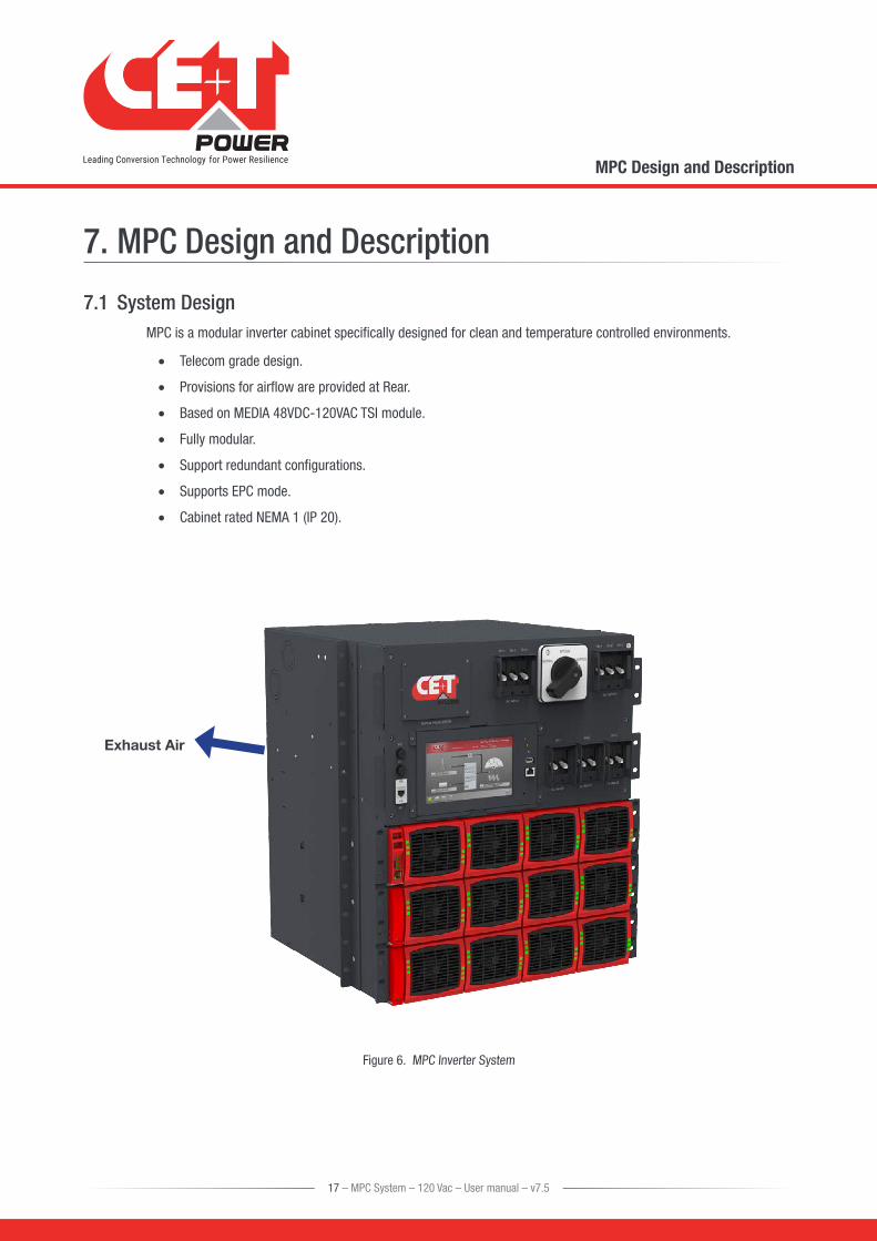
7.1 System DesignMPC is a modular inverter cabinet specifically designed for clean and temperature controlled environments.
• Telecom grade design.
• Provisions for airflow are provided at Rear.
• Based on MEDIA 48VDC-120VAC TSI module.
• Fully modular.
• Support redundant configurations.
• Supports EPC mode.
• Cabinet rated NEMA 1 (IP 20).
Exhaust Air
Figure 6. MPC Inverter System
17 – MPC System – 120 Vac – User manual – v7.5
MPC Design and Description

7.2 System DescriptionThe MPC comes fully equipped with,
• Individual DC supplementary/branch circuit protection for each shelf (Four Modules) (UL 1077).
• T2S interface.
• AC input breaker (bulk)-branch type (UL 1077).
• AC output breaker (bulk)-branch circuit protection (UL 489).
Options
The following accessories are optional for the MPC system.
• Surge Arresters.
• Catena / Candis.
• MBP.
Top View
DC - IN
AC IN/OUT
Catena / Candis
AC OUT Breakers
DC IN Breakers
Inverter Modules
MBP
AC IN Breakers
Surge Arresters
Fuses
RJ45 Port
T2S ETH / T2S USB
Front View Rear View
Figure 7. MPC System - General Arrangement
18 – MPC System – 120 Vac – User manual – v7.5
MPC Design and Description

7.3 MPC Single Phase Configuration - 120 VACA single phase system is 120 VAC from L to N. Input and output are the same, consisting of 2 wires + (PE) Ground.
System DesignationMax Power
(kVA)Max power
(KW)Max number of
Modules
MPC-1-6-xx-04 6 4.8 4
MPC-1-12-xx-08-SUP 12 9.6 8
Table 1. Single Phase 120 VAC - System Details
* This configuration doesn’t use all available slots.
** Up to 2 modules can be allocated to redundancy.
System DesignationSingle DC*** input Individual DC*** input Tightening
Torque (lbs/in)Fuse or
BreakerCable Min
Fuse or Breaker
Cable Min (per feed)
MPC-1-6-xx-04 1 x 150 A 1 x 2/0 AWG NA 275#
MPC-1-12-xx-08-SUP 1 x 300 A 2 x 2/0 AWG 2 x 150 A 1 x 2/0 275#
Table 2. Single Phase 120 VAC - DC Details
# As per local regulations.
*** Refer Section 8.4.4, page 29
System Designation
AC Input AC Output Cable Max
Based on Terminal
Size
Tightening Torque (lbs/in)
Branch Protection Branch Protection
Breaker Cable Min Breaker Cable Min
MPC-1-6-xx-04 1 x 70A / 1P 1 x 4 AWG 1 x 70A / 1P 1 x 4 AWG 1 AWG 25 - 27#
MPC-1-12-xx-08-SUP 1 x 125 A / 1P 1 x 1/0 AWG 1 x 125 A / 1P 1 x 1/0 AWG 2/0 53 - 62#
Table 3. Single Phase 120 VAC - AC Details
# As per local regulations
SUP Supplementary Protection (QVNU2)
19 – MPC System – 120 Vac – User manual – v7.5
MPC Design and Description

7.4 MPC Single Phase Configuration - 240 VACA split phase system* is 120 VAC from L to N and 240 VAC from L1 to L2 are phase shifted by 180 degree (upon request, it can also be 208 VAC. L1, L2 are phase shifted by 120 degree). Input and output consist of 3 wires + (PE) Ground, cabling and phase shift must match.
System DesignationMax Power
(kVA)Max power
(KW)Max number of
Modules
MPC-2-12-xx-08 12 9.6 8**
Table 4. Single Phase 240 VAC - System Details
* Also known as “Single Phase 240 VAC” (including UL). Number of wires is always meaningful to distinguish from other single phase.
** Number of modules must be even, with same number in each phase in order to comply with UL recommendations.
**** Up to 2 x 2 modules can be allocated to redundancy.
System Designation
Single DC***** Input Individual DC***** Input Tightening Torque
(lbs/in)Fuse or Breaker
Cable MinFuse or Breaker
Cable Min (per feed)
MPC-2-12-xx-08 1 x 300 A 2 x 2/0 2 x 150 A 1 x 2/0 275#
Table 5. Single Phase 240 VAC - DC Details
# As per local regulations
***** Refer Section 8.4.4, page 29
System Designation
AC Input AC Output Cable Max
Based on
Terminal Size
Tightening Torque (lbs/in)
Branch Protection Branch Protection
Breaker Cable Min Breaker Cable Min
MPC-2-12-xx-08 1 x 70 A / 2P 1 x 4 AWG 1 x 70 A / 2P 1 x 4 AWG 1 AWG 25 - 27#
Table 6. Single Phase 240 VAC - AC Details
# As per local regulations
Note:
In a 2-phase system, the Mode default setting is a Wye configuration. The setting is such because most of the loads in US are L-L 240 Vac, however, this is not always the case. In the case where there is a L-L 208 VAC, the setting should be a DELTA configuration. To limit the risk of higher fault current, it is recommended that the default setting is the DELTA configuration.
Neutral must be landed on both input and output terminals.
20 – MPC System – 120 Vac – User manual – v7.5
MPC Design and Description
7.5 MPC Three Phase Configuration - 208 VACA Three phase system is 120 VAC from L to N and 208 VAC from L1 to L2, L1 to L3, L2 to L3.
Input and output are made upon 4 wires + (PE) Ground, “Y” or “Star” connection.
All phases are shifted by 120 degrees from one another.
System DesignationMax Power
(kVA)Max power
(KW)Max number of Modules
MPC-3-18-xx-12 18 14.4 12 *
Table 7. Three Phase 208 VAC - System Details
* Number of modules must be multiple of 3, with same number in each phase in order to comply with UL recommendations.
System Designation
Single DC** Input Individual DC** Input Tightening Torque (lbs/in)Fuse or
BreakerCable Min
Fuse or Breaker
Cable Min (per feed)
MPC-3-18-xx-12 1 x 450 A 3 x 2/0 3 x 150 A 1 x 2/0 275#
Table 8. Three Phase 208 VAC - DC Details
# As per local regulations
** Refer Section 8.4.4, page 29
System Designation
AC Input AC Output Cable Max
Based on
Terminal Size
Tightening Torque (lbs/in)
Branch Protection Branch Protection
Breaker Cable Min Breaker Cable Min
MPC-3-18-xx-12 1 x 70 A / 3P 1 x 4 AWG 1 x 70 A / 3P 1 x 4 AWG 1 AWG 25 - 27#
Table 9. Three Phase 208 VAC - AC Details
# As per local regulations
Note:
Three phase systems with 2 legs instead of three can be requested. They are called 1P/6 KVA or 2P/12 KVA. Effectively they are based upon the same hardware as split phase (see 7.4, page 20) with 3 wires (L1-L2-N). Since phases are shifted by 120 degree the L1 - L2 output voltage is 208 VAC.
Neutral must be landed on both input and output terminals.
21 – MPC System – 120 Vac – User manual – v7.5
MPC Design and Description

7.6 MPC Module based Current Ratings
Number of ModulesRated AC Input/Output Current per
Phase (Amps)Rated DC Input Current (Amps)
120 Vac - Single Phase - 2 Wires + PE
1 12.50 27.75
2 25.00 55.50
3 37.50 83.25
4 50.00 111.00
5 62.50 138.75
6 75.00 166.50
7 87.50 194.25
8 100.00 222.00
120/240 Vac - Single Phase - 3 Wires + PE
2 12.50 55.50
4 25.00 111.00
6 37.50 166.50
8 50.00 222.00
120/208 Vac - Three Phase - 4 Wires + PE
3 12.50 83.25
6 25.00 166.50
9 37.50 249.75
12 50.00 333.00
Upstream / downstream protections and field wiring should be based on the maximum number of modules
Table 10. Module Current Details
22 – MPC System – 120 Vac – User manual – v7.5
MPC Design and Description

8. System Installation
8.1 Site Preparation • Input and output protections.
When installing MPC inverter systems, UL489 listed AC upstream (input) and downstream (output) circuit breakers are required. Refer to Section 7.3, 7.4, and 7.5 for breaker sizes.
At MPC Input
Branch circuit protection breaker should be provided in upstream switchgear or panel board regardless of any protective device already installed at the input of the MPC.
At MPC Output
Branch circuit protection breaker (UL 489) should be provided in downstream switchgear or panel board regardless of any protective device already installed at the output of the MPC.
Output distribution protective devices should be sized to guarantee proper coordination with upstream and downstream protective devices. Contact the breaker manufacturer for recommendations and calculation methodology.
• Refer to Section 7, page 17 for sizing over current protection and cables. All cables should be copper wire and must be rated for min 90°C (194°F).
• All cables must be C-UL-US or CSA Listed cables.
• All cables lugs must be C-UL-US or CSA listed. They must be sized according to the rated current of the inverter system and to the customer terminal connection.
• Wire all positions for future expansion.
• All AC input, AC output, DC input, and signal cables shall be kept separated.
• Cable crossings shall be arranged at 90 degree angles.
• Empty inverter positions shall be covered with dummy cover.
• System cooling – The MPC should not be installed with the rear of the unit at, near, or up against a wall.
� A minimum of 36 inch clearance is required at the rear of the unit.
� A minimum of 6 inch clearance is required on top of the cabinet.
� Air inlets are at the front of the system and air exhaust outlets are at the top and rear of the system.
• The MPC is designed to operate in a temperature controlled (maximum operating ambient 40°C/104°F) and clean environment. The presence of airborne particles such as dust, sand and metallic debris are forbidden. Appropriate filters shall be installed.
• Heat Load Calculation - The system heat loss can be calculated by taking the system size in KW and multiplying by 375.2 BTU/hr.
Warning:
Filters mounted to the air inlets reduce the air pressure and may cause inverters to cut off by thermal runaway. De-ratings should apply. Refer to supplier for specific recommendations and approvals.
Corrosive chemicals and contaminants in the air or in the vicinity of the system are forbidden. Refer to supplier for specific treatments in industrial and maritime areas.
23 – MPC System – 120 Vac – User manual – v7.5
System Installation

8.1.1 Transformer and Generator Sizing
The inverter is capable of operating at 150% of rated capacity for 15 seconds. The boost function allows up to 10 times the rated inverter capacity for 20 ms to clear downstream faults.
• Transformers supplying AC to the inverter should be sized at a minimum of 1.5 times the kVA rating of the inverter to meet this requirement.
• Generators supplying emergency AC to the building and to the inverter should be sized at a minimum of 2 times the kVA rating of the inverter.
8.2 Packing InformationModules are packed separately. They are marked to be installed in the pre addressed slot (important for multi phase systems). Module packing material should be taken apart and stored in case of return under warranty. Improper packing on shipment may void the factory warranty.
The MPC cabinet is packed in a wooden box.
The packing material of the TSI system is recyclable.
Transport the cabinet in the box on the pallet.
8.3 Rack Installation of the MPCCE+T offers adapter plates to mount the MPC into the 23-inch open relay racks. These are included in the accessory kit shipped with the unit.
All MPC systems are designed for 19-inch mounting applications, but can be mounted in a 23-inch, two post, open relay rack/ network frame assembly if required.
Note: Mounting adapters are not intended for use in 4 post relay rack.
Fix the Brackets, Bottom Support / Slide rails to the rack using the screws supplied along with the mounting kit and then install the system in the rack as shown in the following figure.
Figure 8. Installing MPC system in Rack
24 – MPC System – 120 Vac – User manual – v7.5
System Installation

8.4 CablingCheck section 7 to identify system configuration and refer to section 7.3, page 19, 7.4, page 20, and 7.5, page 21 for cable sizes. Refer also to 8.1, page 23 for important safety notices.
8.4.1 Conduit Entry
Use appropriate conduit fitting to install the conduits to the cabinet. Use existing knock outs to install the cables so as not to block the airflow through the top of the cabinet.
For AC IN and AC OUT conduits, Conduit knockouts are present at the top and left side of the cabinet.
For connection of the DC cables, the conduit knockouts are provided on the rear of the cabinet.
Cables entrances should be protected by bushings, UL category NZMT2, rated for minimum 50°C.
DC - Conduit Knockouts AC - Conduit Knockouts
Dimensions are in mm
Figure 9. System Knockout details
8.4.2 Cabinet Grounding
The Main ground conductor(PE) connection is made to the X2 (AC IN) terminal block marked with symbol for identification.
Ground cable connection must be terminated even if commercial AC is not available and shall be connected to building or panel ground per NEC. (see 8.4.3, page 26)
Ground has to be connected in accordance with local code.
Chassis ground connection is internal on side of unit.
25 – MPC System – 120 Vac – User manual – v7.5
System Installation

Both PE (Protective Ground) is connected to Grounding Stud. It is factory wired and should not be removed.
Figure 10. Earthing connections
8.4.3 AC Input and Output
The pictorial representation of terminal blocks arrangement is as follows.
If AC IN is connected, remove the bonding neutral jumper cable between AC IN Neutral and PE terminal.
Figure 11. Neutral Bonding Jumper
Note: When AC mains is not connected, the output AC circuit is considered as a separately-derived source. If local codes require grounding of this circuit, use the PE output terminal bonding that circuit to the enclosure and ground the enclosure to a suitable grounding electrode in accordance with local code requirements.
26 – MPC System – 120 Vac – User manual – v7.5
System Installation

AC input and AC output should be wired to terminal blocks per following indications:
Figure 12. AC Input and Output Connections
8.4.3.1 Single Phase 2 Wires + PE Connection
Figure 13. Single Phase 2 Wires + PE Connection
27 – MPC System – 120 Vac – User manual – v7.5
System Installation

8.4.3.2 Single Phase 3 Wires + PE Connection
Figure 14. Single Phase 3 Wires + PE Connection
8.4.3.3 Three Phase 4 Wires + PE Connection
Input and Output cable connections must be in clockwise configuration ABC
Figure 15. Three Phase 4 Wires + PE Connection
28 – MPC System – 120 Vac – User manual – v7.5
System Installation

8.4.4 DC Input Terminal Connection
Figure 16. DC Input - Terminal Connection
8.4.4.1 Single Feed DC Input
• It is mandatory to use only C-UL-US or CSA listed Cable Lugs.
• One (1) common DC connection.
• Note: Cable lugs are not included in the delivery.
• 2 holes of 3/8” (M10) hole with 1”(25.4mm) between center .
• Internal DC distribution with circuit breakers to each shelf.
• Max 3 x 2/0 .
• Can be single or double hole lug (refer to site requirement for right type).
Figure 17. Single Feed DC - Arrangement
29 – MPC System – 120 Vac – User manual – v7.5
System Installation

Figure 18. Single Feed DC - Wiring
30 – MPC System – 120 Vac – User manual – v7.5
System Installation

8.4.4.2 Individual Feed DC Input
• It is mandatory to use only C-UL-US or CSA listed Cable Lugs.
• Individual DC connection.
• Note: Cable lugs are not included in the delivery.
• 2 hole 3/8” (M10) holes with 1”(25.4mm) between center.
• The positive field wiring terminal shall be grounded on the rectifier.
• Internal DC distribution with circuit breakers to each shelf.
• Max 1x2/0.
• Can be single or double hole lug (refer to site requirement for right type).
• For Individual Feed DC Input, remove the common copper plate on the terminals.
Common copper plate is always present on the terminals.
Figure 19. Individual Feed DC - Arrangement
31 – MPC System – 120 Vac – User manual – v7.5
System Installation

Figure 20. Two or Three Feed DC - Arrangement
32 – MPC System – 120 Vac – User manual – v7.5
System Installation

8.4.5 Customer Field Connections
All relays are shown in non energized state.
Figure 21. Alarm Dry ContactsNote:
Output relays are time delayed factory default set to 30 seconds, User settable from 2 to 30 seconds.
To connect “Inverter in Bypass” status signal from inverter to External Manual Bypass (MBP) Switch, connect external MBP to X3 terminals 7 and 9.
8.4.5.1 Alarm (X3)
• Relay characteristics X3 (Major (UA), Minor(NUA), Prog) - Switching power 60 W - Rating 2 A at 30 VDC / 1 A at 60 VDC - Max wire size 17 AWG (1 mm2)
Relays are energized when idle and contacts are released when event occurs.
8.4.5.2 Digital IN (X5) Surge Arrestor
• Input characteristics X5 (Digital In 1, Digital In 2) - Signal voltage +5 VDC (galvanically isolated) - Max wire size 17 AWG (1 mm2) Note: Not available if internal MBP is installed.
33 – MPC System – 120 Vac – User manual – v7.5
System Installation

8.4.5.3 Remote ON/OFF (X6)
Note: The system is by default equipped with a connection between pin 3 and 2. If remote ON/OFF is not used the strap shall remain. Should the remote ON/OFF be used the strap must be replaced with a changeover contact or emergency button.
• The remote ON/OFF turns the AC output OFF.
• Input AC and input DC is not affected by the remote ON/OFF.
• The remote ON/OFF requires changeover contacts, one input opens as the other closes. If both transitions are not picked up the status is not changed.
• Digital input characteristics (Remote ON/OFF) - Signal voltage +5 VDC (galvanically insulated) - Max wire size 17 AWG (1 mm2)
Functional table for remote ON/OFF function
S.NO Pin 1-3 Pin 2-3 Status Indication
1 Open Open Normal operation All (Green)
2 Closed Open OFFAC output (OFF) AC Input (Green) DC Input (Green)
3 Open Closed Normal operation All (Green)
4 Closed Closed Normal operation All (Green)
Figure 22. Remote ON/OFF Operation
Warning: If remote ON/OFF not used, pin 2 and 3 MUST be bridged together!
34 – MPC System – 120 Vac – User manual – v7.5
System Installation

9. Human-Machine Interface
9.1 Inverter module
Inverter Status LED Description Remedial action
OFF No input power or forced stop Check environment
Permanent green Operation
Blinking greenConverter OK but working conditions are not fulfilled to operate properly
Blinking green/orange alternativelyRecovery mode after boost (10 In short circuit condition)
Permanent orange Starting mode
Blinking orange Modules cannot start Check T2S
Blinking red Recoverable fault
Permanent red Non recoverable fault Send module back for repair
Output Power (redundancy not counted)
<5%5% to 40%
40 to 70%
80 to 95%
100%100% = overload
Output Power (redundancy not counted)
× × ×
Status output power LED× ×
×
1B 1P 2P 2P 3P 3B Behaviour (B = Blinking, P = Permanent )
9.2 T2S • Alarm indication on T2S (Urgent / Non Urgent / Configurable)
- Green: No alarm - Red: Alarm - Flashing Exchanging information with inverters (only Configurable alarm)
• Outgoing alarm relay delay - Urgent 60 seconds delay - Non urgent 30 second delay
• Parameter setting via USB connection to Latptop.
• Factory default according to list of set values.
Figure 23. T2S ETH Front Details
35 – MPC System – 120 Vac – User manual – v7.5
Human-Machine Interface
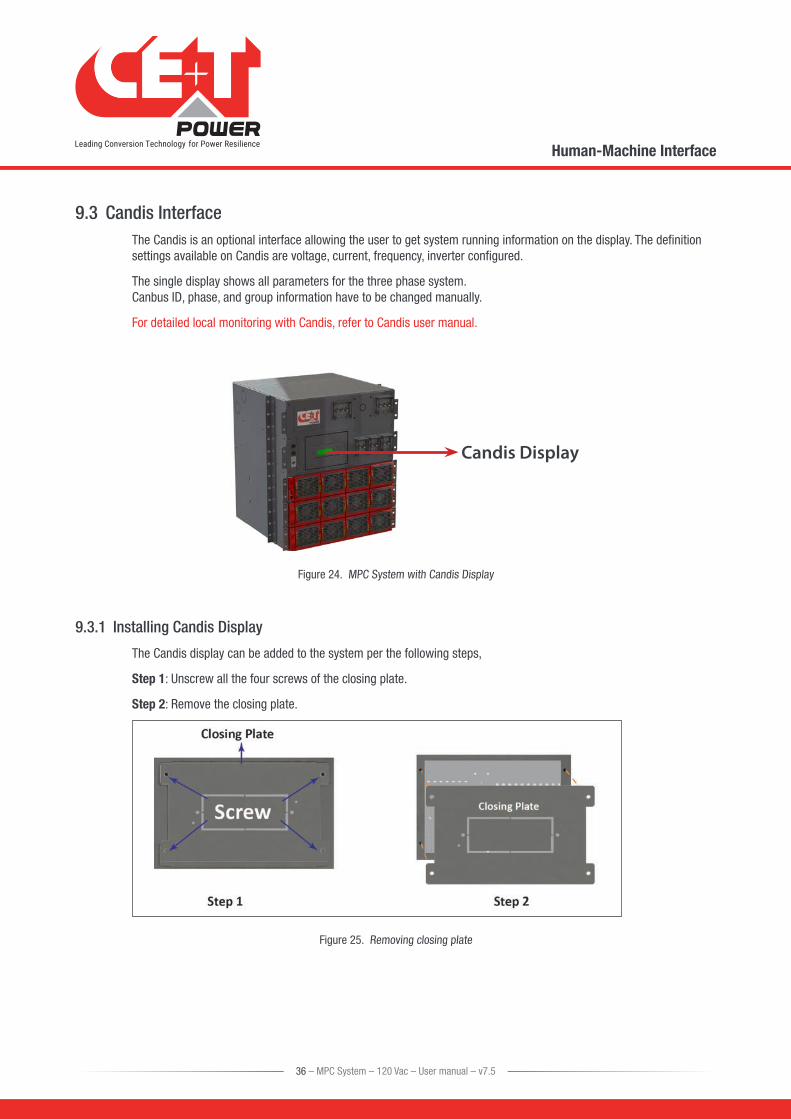
9.3 Candis InterfaceThe Candis is an optional interface allowing the user to get system running information on the display. The definition settings available on Candis are voltage, current, frequency, inverter configured.
The single display shows all parameters for the three phase system. Canbus ID, phase, and group information have to be changed manually.
For detailed local monitoring with Candis, refer to Candis user manual.
Candis Display
Figure 24. MPC System with Candis Display
9.3.1 Installing Candis Display
The Candis display can be added to the system per the following steps,
Step 1: Unscrew all the four screws of the closing plate.
Step 2: Remove the closing plate.
Figure 25. Removing closing plate
36 – MPC System – 120 Vac – User manual – v7.5
Human-Machine Interface
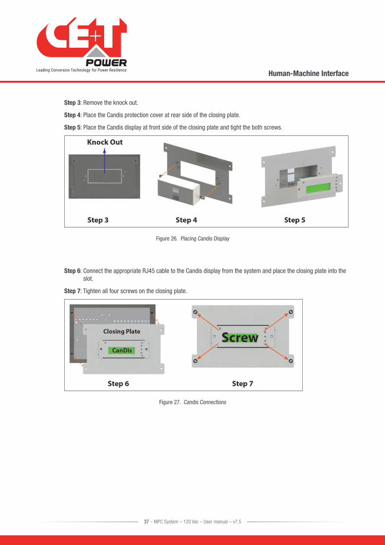
Step 3: Remove the knock out.
Step 4: Place the Candis protection cover at rear side of the closing plate.
Step 5: Place the Candis display at front side of the closing plate and tight the both screws.
Figure 26. Placing Candis Display
Step 6: Connect the appropriate RJ45 cable to the Candis display from the system and place the closing plate into the slot.
Step 7: Tighten all four screws on the closing plate.
Figure 27. Candis Connections
37 – MPC System – 120 Vac – User manual – v7.5
Human-Machine Interface
9.3.2 Replacing Candis Display
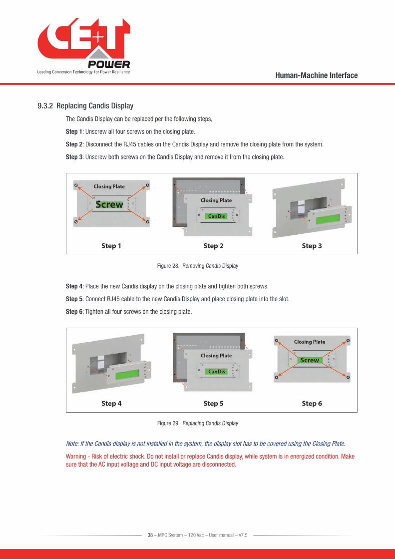
The Candis Display can be replaced per the following steps,
Step 1: Unscrew all four screws on the closing plate.
Step 2: Disconnect the RJ45 cables on the Candis Display and remove the closing plate from the system.
Step 3: Unscrew both screws on the Candis Display and remove it from the closing plate.
Figure 28. Removing Candis Display
Step 4: Place the new Candis display on the closing plate and tighten both screws.
Step 5: Connect RJ45 cable to the new Candis Display and place closing plate into the slot.
Step 6: Tighten all four screws on the closing plate.
Figure 29. Replacing Candis Display
Note: If the Candis display is not installed in the system, the display slot has to be covered using the Closing Plate.
Warning - Risk of electric shock. Do not install or replace Candis display, while system is in energized condition. Make sure that the AC input voltage and DC input voltage are disconnected.
38 – MPC System – 120 Vac – User manual – v7.5
Human-Machine Interface

9.4 Catena GUI InterfaceThe Catena GUI Interface is a powerful web based touch screen graphical display, it allows the user to easily access and monitor the system.
In addition to the touch screen display, the user can also access to same GUI by using an Ethernet port which is present on the Catena.
The Catena takes power from shelf one. DC power supply to shelf one is necessary to power on the Catena.
The Catena GUI Interface is protected with a Fast Acting Fuse, which is present at the front left side of the Catena. In case of fuse failure, replace with same type and rating of fuse.
Fuse details are listed below:
ManufacturerManufacturer Part
NumberCurrent Rating Voltage Rating Fuse Size/Group
Schurter 0001.2507 2 A 250 VAC / 300 VDC 5 x 20 mm
Table 11. Fuse Details
9.4.1 Installing Catena GUI Interface
The Catena GUI Interface can be added to the system per the following steps:
Step 1: Unscrew all four screws of the catena closing plate.
Step 2: Remove the Catena closing plate.
Figure 30. Removing closing plate
39 – MPC System – 120 Vac – User manual – v7.5
Human-Machine Interface

Step 3: Connect the power and Cat-5e cable to the Catena GUI Interface and place it into the slot.
Step 4: Tighten all four screws on the Catena GUI Interface.
Figure 31. Placing Catena Display
9.4.2 Replacing the Catena GUI Interface
The Catena GUI Interface can be replaced into the system as per the following steps:
Step 1: Unscrew all four screws on the Catena GUI interface.
Step 2: Disconnect appropriate cables in the Catena GUI Interface and remove it from the system.
Figure 32. Removing Catena Display
40 – MPC System – 120 Vac – User manual – v7.5
Human-Machine Interface

Step 3: Connect the power and Cat-5e cable to the Catena GUI Interface and place it into the slot.
Step 4: Tighten all four screws on the Catena GUI Interface.
Figure 33. Placing Catena Display
Note: If the Catena GUI Interface is not present in the system, the slot has to be covered using Catena Closing Plate.
Warning: Risk of electric shock, do not replace the Fast Acting Fuse in system running condition.
Warning: Risk of electric shock. Do not install or replace Catena GUI Interface, while system is energized. Make sure that AC input voltage and DC input voltage are disconnected.
41 – MPC System – 120 Vac – User manual – v7.5
Human-Machine Interface

10. System set upThe MPC System is delivered with default set of parameters referred to as factory settings.
The standard configuration will be as shown below:
• Candis with T2S USB
• Catena with T2S ETH
**There is a possibility to have above configuration changed upon customer request.
10.1 T2S USBUpon various site operating conditions or Site Manager requirements some parameters might have to be adjusted.
Refer to “TSI T2S 120 VAC User Manual Vx_x” for detailed description of system status reading and changing as well as parameter adjustment.
• Parameter set up requires Hyper terminal installed on laptop.
• USB cable type A to B (not included).
• T2S driver “CET_T2S.inf” installed on laptop.
• Available for download: - On my.CET for direct customers, in the “Document” section. - At the following URL for everyone else: http://www.cet-power.com/uploads/Driver_T2S/Driver_T2S_for_Windows_and_hyperterminal.zip.
10.1.1 Communication Setting
• Bits per second 9600
• Data bits 8
• Parity None
• Stop bits 1
• Flow control None
Figure 34. T2S USB - Port Settings
42 – MPC System – 120 Vac – User manual – v7.5
System set up

10.1.2 Menu accessRoot Menu
1 > System configuration
0 > Return to previous menu
1 > Send config file to T2S
2 > Read config file from T2S
3 > Restore default settings (no more available since version 2.5)
4 > Restore factory settings (no more available since version 2.5)
2 > System information’s selection
0 > Return to previous menu
1 > Module information’s 0 > Return to previous menu 1 > Variables set 1 2 > Variables set 2 3 > Variables set 3 4 > Variables set 4 + > Next page - > Previous page
2 > Phase information 0 > Return to previous menu 1 > Variables set 1 2 > Variables set 2 3 > Variables set 3
3 > Groups information 0 > Return to previous menu 1 > Display AC group information 2 > Display DC group information
4 > Alarms information 0 > Return to previous menu 1-1 > Page selection
5 > History of the log display 0 > Return to previous menu 1-14 > Page number selection 16 > Clear log 17 > Save log to a file
6 > Module errors information
0 > Return to preceding menu 1-32 > Detailed Modules errors
3 > System actions selection 0 > Return to previous menu
1 > System actions 0 > Return to index 1 > Turn ON system 2 > Turn OFF system 3 > Change Date and time setting
2 > Inverter Module action 0 > Return to previous menu 1-4 > Page number selection 5 > Identify selected Module 6 > Turn ON selected Module 7 > Turn OFF selected Module 8 > Change address of sel. Module 9 > Change phase of selected Module 10 > Automatic address assignment 11 > Change DC group of selected Module 12 > Change AC group of sel. Module 13 > Notify changed fan of sel. Module
+ > Increment selector - > Decrement selector
3 > T2S actions 0 > Return to index 1 > Force refresh of configuration texts and constants 2 > Force refresh of events description texts
4 > Security Access
0 > Return to index
1 > Enable Password protection
43 – MPC System – 120 Vac – User manual – v7.5
System set up

10.2 T2S Ethernet via CatenaOnce system is powered upon, the Catena is up and ready for operation.
Configuration and other parameters can be changed using the Catena interface.
10.2.1 User GUI Interface Catena
Figure 35. Catena - Home Page
CATENA provides a quick and efficient user interface to:
• Get and overview of the system information
• Detail information on
� AC input power at system level
� AC output power at system level
� DC information at system level
� Inverters information module level
44 – MPC System – 120 Vac – User manual – v7.5
System set up

10.2.1.1 CATENA Start up
Applying start-up power – web interface
Initiate the start-up routine by applying power to the CATENA.
Note:
The controller will perform a short self-test as it boots up. Alarm alerts are normal.
Since CATENA software v4.4.0, units equipped with a front RJ45 port; set computer to “obtain IP automatically” and direct web-browser to http://catena.local (don’t forget the dot).
Customer network connect (with static IP) is on rear of unit.
Use the touch screen or connect the computer to the ETHERNET port and start your web browser.
1. Point your browser to 192.168.0.2 (default address).
2. Choose a user type (Basic or expert) and enter your password. Default password is “pass123” for basic, “pass456” for expert.
Note: Default keyboard entry setting is with “CAPS LOCK ON”, Password must be entered in lower case, change keyboard to lower case setting before entering password.
Figure 36. Catena - Login page
45 – MPC System – 120 Vac – User manual – v7.5
System set up
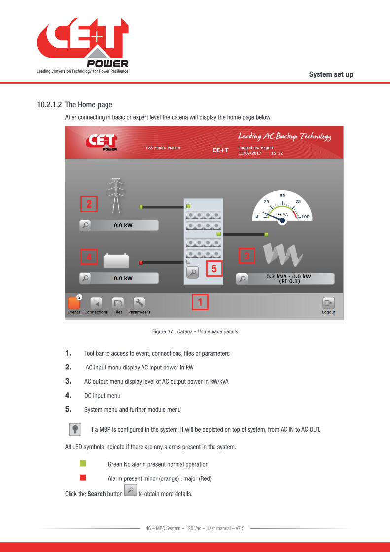
10.2.1.2 The Home page
After connecting in basic or expert level the catena will display the home page below
1
2
345
Figure 37. Catena - Home page details
1. Tool bar to access to event, connections, files or parameters
2. AC input menu display AC input power in kW
3. AC output menu display level of AC output power in kW/kVA
4. DC input menu
5. System menu and further module menu
If a MBP is configured in the system, it will be depicted on top of system, from AC IN to AC OUT.
All LED symbols indicate if there are any alarms present in the system.
Green No alarm present normal operation
Alarm present minor (orange) , major (Red)
Click the Search button to obtain more details.
46 – MPC System – 120 Vac – User manual – v7.5
System set up

10.2.1.3 The AC input page
Click the Search button at AC input to obtain detail AC input information of the 3 phases:
This screen provides the following information:
• AC input voltage for each phase
• AC input current per phase
• Frequency
• Input power going to the Media inverter
• Record the last AC input failure date and time
Figure 38. Catena - AC Input page
10.2.1.4 The DC input page
Click the Search button at DC input to obtain detail DC input information:
This screen provides the following information:
• DC input voltage VDC
• DC input current
Figure 39. Catena - DC Input page
47 – MPC System – 120 Vac – User manual – v7.5
System set up

10.2.1.5 The AC output page
Click the Search button at AC output to obtain detail AC output information
Figure 40. Catena - AC Output page
This screen provides the following information:
• Graph indicating the power per phase of N (Not N+1), system capacity calculation does not includes redundant modules.
• AC output voltage for each phase
• AC output current per phase
• Frequency
• AC output power (kW)
• Apparent power (kVA)
LEDs indicate any alarm and on which phase (Green no alarm) Red (Alarm)
48 – MPC System – 120 Vac – User manual – v7.5
System set up

10.2.1.6 The System page
Click the Search button at the cabinet in the home page will bring you to the system page where following information can be found:
System level:
• Installed power
• Available power
Phase level:
For each output phase, following information is given:
• Number of installed modules
• Redundancy: defined or not, satisfied or not
• Installed and available power following the same logic as per system level
• A.R.C. (Available Redundant Capacity) is the remaining available power before reach the redundancy level.
Clicking the button will launch the module selection popup.
Each module information can be accessed by clicking the corresponding button.
A legend is always present to recall the color scheme:
• White: no module in slot
• Grey: module manually off
• Green: module OK
• Orange: module in recoverable error
• Red: module with unrecoverable error
For last two, refer to module manual for troubleshooting.
Module Page
This page gives module by module measurement.
T2S ETH is the monitoring solution for inverters which are all one phase modules.
Many controls are available from this page to manage the module:
The T° probe is the average T° of the inverter module heat sink
Figure 43. Catena - Module page
Figure 41. Catena - System page
Figure 42. Catena - Module list
49 – MPC System – 120 Vac – User manual – v7.5
System set up

10.2.2 The TOOLBAR
Figure 44. Catena - Tool bar
At the bottom of the screen a permanent “Tool bar” populated with different buttons
10.2.2.1 Events
The circled number indicates the number of active alarms.
Click the Events button , Events page opens and list all events currently ongoing in the system. These are sorted by appearing time, newer on top of the list.
“Device” column provides the source of the alarm which can be down to inverter of a given module (example: module 4 AC IN) to System or monitoring level.
Events appear with a color corresponding to their alarm level (grey – event, orange – minor, red – major).
A filter as shown below is available to display only a subset of these events.
10.2.2.2 Log
Click the Log button to access the log file which is a record of last 500 events with date and time the occurred in the system.
Compared to event page, an extra column is displayed if event has appeared or disappeared.
For each event, there are two log lines: one with the timestamp of the event appearing and the second one with the timestamp of the event disappearing.
User can filter the log like the event page.
User is able to see the difference between event and log page: no color for alarm level is used in log page, a column states it.
Log download and clear functions are available in “Files” menu.
Figure 45. Catena - Events page
Figure 46. Catena - Logs page
50 – MPC System – 120 Vac – User manual – v7.5
System set up

10.2.2.3 Connections
Click on Connections button to access the mapping of the digital inputs and relays output.
T2S ETH has 2 digital inputs and 3 alarm relays.
State of each of these connections can be read through the “connections” page.
An extra button “toggle” allows the user to test each relay manually, toggling it for a few seconds with the aim of detecting a mechanically failing device over the time.
10.2.2.4 Files
Click on Files to:
• Export the log file
• Clear the log file (only possible in expert mode)
• Upgrade the software of the T2S ETH unit.
• Upload a language file.
10.2.2.5 Parameters
To define and setup all communication parameter listed below and please do not change setting below unless necessary.
The Parameters page is divided into tabs which are a compound of sub menus:
• Monitoring
• Input/Relays
• Power
• Info
Figure 47. Catena - Connections page
Figure 48. Catena - Files page
Figure 49. Catena - Parameters page
51 – MPC System – 120 Vac – User manual – v7.5
System set up
10.3 Switching OFF MPC SystemPerform the following steps to Switch OFF the MPC System.
Caution: While switching OFF the MPC System the power to load will be disconnected.
1. Switch OFF AC Output Breakers.
2. Switch OFF AC Input Breakers.
3. Switch OFF DC Input Breakers.
4. Switch OFF the Upstream and Downstream and By-Pass Breakers. (As applicable)
Caution – Risk of electric shock. Capacitors store hazardous energy. Do not remove the system from the cabinet at least five minutes after disconnecting all sources of supply.
Caution - Risk of electric shock. This inverter receives power from more than one source. Disconnection of AC source and DC source is required to de-energize this unit before servicing.
52 – MPC System – 120 Vac – User manual – v7.5
System set up

11. Inserting/removing/replacing modules
11.1 TSI Inverter Module • The TSI inverter module is hot swappable.
• When a new module is inserted in a live system it automatically takes the working set of parameters.
• When a new module is inserted in a live system it is automatically assigned to the next available address.
11.1.1 Removal
Notice: When one or several inverter modules is/are removed, live parts become accessible. Replace module(s) with dummy cover without delay.
• Inverter module is not switched off when opening the handle. The handle only hooks the module to the shelf.
• Use a screw driver to release the latch of the handle.
• Open the handle and Pull the module out.
• Replace with a new module or dummy cover.
A) Use screwdriver to release the latch B) open the cover completely C) Use the cover as a handle to remove the module
Figure 50. Module Removal
11.1.2 Inserting
• Check module compatibility (DC Voltage!).
• Use a screw driver to release the latch of the handle.
• Open the handle and Push firmly until the unit is properly connected.
• Close the cover and latch in position.
A) Slide the module in B) Push firmly till the connection is properly engaged
C) Close the cover and latch the module in place if too hard redo step B
Figure 51. Module Inserting
53 – MPC System – 120 Vac – User manual – v7.5
Inserting/removing/replacing modules
11.2 T2S
11.2.1 Removal
• Use a small screw driver to release the latch keeping the T2S in position.
• Pull the T2S out.
Insert screw driver Release the latch
Figure 52. T2S Removal
11.2.2 Inserting
• Push the T2S firmly in place until the latch snaps in position.
11.3 Fan replacementThe FAN life is approximately 60,000 (Sixty thousand) hours. The inverter modules have fan runtime meters and fan failure alarm. Fan failure can result from failing fan or driver circuit.
• Let the module rest at least 5 minutes prior to initiating work.
• The inverter front must be removed. Use a blunt tool to depress the latches on the module side fixing the front to the module.
• Remove the fan and unplug the supply cord.
• Replace with new fan and connect supply cord.
• Replace front, make sure that the front latch properly.
• Plug in.
• Check fan for operation.
• Access T2S and reset the fan run time alarm from within the action menu.
Figure 53. Module Fan Replacement
54 – MPC System – 120 Vac – User manual – v7.5
Inserting/removing/replacing modules

12. Manual By-Pass OperationManual By-Pass has to be operated by trained people only.
When system is in manual by-pass the load is subjected to mains AC voltage without active filtering.
An MBP Engaged output alarm will occur when the system is in manual by pass.
The Manual By-Pass is not possible to operate remotely.
MBP switch is optional.
MBP switch must be present if using with a non-CE+T external MBP.
12.1 Pre requisitesBefore engaging the MBP following conditions have to be fulfilled and actively checked.
• Commercial AC must be present.
• Inverter must be synchronized with commercial power.
� Use Voltmeter to measure voltage between L1- commercial and L1 - inverter output.
� Do same measurement with L2 – L2 and L3 – L3.
� In all cases, voltage must be less than 20 V.
• The upstream AC & DC breaker must be correctly sized (Refer 7.3, page 19) to accept possible overload, The inverter might be overloaded during MBP procedure, depending on voltage network and output inverter voltage setting and if the AC is supplied by a Gen-set, the minimal required power will be twice nominal power of the inverter.
It is requested in order to reduce the inrush current during manual by pass operation to adjust the converter AC output voltage to the same value as AC input voltage. If the difference between AC input and AC output voltage exceed 5 Vac, there is a risk of shut down of inverter due to high inrush current during the return to normal operation from Manual By Pass engaged.
12.2 Manual By-Pass OperationThe manual By-Pass operates via individual switch that creates a by-pass from mains input via output AC distribution. Inverter modules are by-passed and possible to disconnect without impacting the load.
Operation is “Make before Break”.
55 – MPC System – 120 Vac – User manual – v7.5
Manual By-Pass Operation

12.2.1 Normal to By-Pass, Engage MBP
1. Turn the switch from NORMAL to BYPASS. (Do not stop at INTERIM Position)
2. Switch DC OFF.
Manual By-Pass puts the module in OFF state but doesn’t disconnect the DC. Make sure DC is disconnected before any intervention inside the system.
Warning: Risk of electric shock. Power will be available at AC Input terminal, AC Output terminal, DC Input terminal, and Surge Arresters.
12.2.2 By-Pass to Normal, Disengage MBP
1. Switch DC ON, wait for DC LED to turn green.
2. Turn switch to INTERIM (mid position).
3. PAUSE: Wait until the inverter modules have come to full operation and have synchronized (less than 20 seconds).
4. Turn switch to NORMAL.
WARNING
IF ATS (automatic transfer switch) IS INSTALLED UPSTREAM TO SELECT AC SOURCE. MAKE SURE THAT THE ATS SWITCH DOES NOT ALLOW TRANSFER BETWEEN AC SOURCE OUT OF SYNC. THE MAXIMUM ALLOWED PHASE SHIFT IS 10°.
Figure 54. MBP Switch
56 – MPC System – 120 Vac – User manual – v7.5
Manual By-Pass Operation

13. Final Check • Make sure that the sub-rack and cabinet is properly fixed to the cabinet/floor.
• Make sure that the sub-rack/cabinet is connected to Ground.
• Make sure that all DC and AC input breakers are switched OFF.
• Make sure that all cables are according to recommendations and local regulations.
• Make sure that all cables are strained relived.
• Make sure that all breakers are according to recommendation and local regulations.
• Make sure that DC polarity is according to marking.
• Re tighten all electrical terminations.
• Make sure that no inverter/controller positions are left open.
• Cover empty inverter positions with dummy cover.
• Make sure that the Remote ON/OFF is appropriately wired according to local regulations.
• Make sure that the point of AC supply meets local regulations.
57 – MPC System – 120 Vac – User manual – v7.5
Final Check

14. Installation & Commissioning of TSI SystemsCAUTION!
• Installation and commissioning must be completed by factory trained personnel.
• It is prohibited to perform any High Potential (HI-POT) insulation test without instruction from the manufacturer.
General Information
Date / Time of Installation:
Commissioning Contractor:
Company:
CE+T Authorization Number:
Electrical Contractor:
Company:
Site Address:
City, State, Zip:
End User Contact & Phone:
System Part Number: ABC - # - ## - XX - ##
System Serial Number: #### / ####
Inverter Modules Serial #
Phase 1
Phase 2
Phase 3
HMI (Circle one) CANDIS CATENA
T2S S/N: Version:
IP Setting IP Address Subnet mask Default gateway
The scope of this document is to provide a general guide for the installation contractor. Please refer to the operation manual for more details. Specific manuals for inverter systems and monitoring devices are available upon request at [email protected].
For any step resulting in a failure on the procedure, an explanatory note must be included. Failure to include explanatory note may result in delay in processing any future warranty claim.
58 – MPC System – 120 Vac – User manual – v7.5
Installation & Commissioning of TSI Systems

14.1 Installation Check List
Electrical Contractor (Pre-Startup) Checklist PASS FAIL NA
1 Check if the AC source transformer is 1.5 X maximum capacity of inverter system.
2 Check if the generator is 2 X maximum capacity of inverter system.
3 Verify cable entry supports are properly secured.
4Verify input utility breakers will not be overloaded based on additional AC load added to the building.
5Check conductor size and breaker protection rating for AC input and Output cables, and DC input cables.
6 Verify that the inverter chassis is correctly bonded to GROUND / EARTH.
7Verify all contractor field connected cable terminations are torqued properly per “TABLE 1”.
8Verify that the inverter cabinet is properly secured, anchored and has proper rear clearance. (Minimum 36” per NEC 110.26).
9 Verify AC input cables are terminated properly on input terminal X2.
10 Verify AC output cables are terminated properly on output terminal X4.
11Verify Ground / Earth (PE) connection is terminated properly even if AC input is not connected.
12If AC input is connected to the system, remove the Neutral to Ground bonding jumper on input terminal X2.
13If no AC input is connected to the system, verify the Neutral to Ground bonding jumper is installed on input terminal X2.
TABLE 1
AC Connections (per Mfg) DC Connections (per NEC)
Media 2i 0.5-0.6 Nm Wire Size Torque
MPC (L1, L2, L3) 3 Nm 2 – 1 16.9 Nm
MPC (N & G) 7 Nm 1/0 – 2/0 20.3 Nm
HD 22.5 Nm 3/0 – 4/0 28.2 Nm
RBS 2.8-3.0 Nm 250 – 350 36.7 Nm
MIPS (see note 1) 6 Nm 500 42.4 Nm
MIPS (see note 2) 20 Nm 600 42.4 Nm
750 42.4 Nm
Dry Contacts Terminal Block 0.4-0.6 Nm
Note 1: For MIPS, small terminal block is for MIPS-1-10, MIPS-2-20, MIPS-3-30
Note 2: For MIPS, large terminal block is for MIPS-1-20, MIPS-1-25, MIPS-2-40, MIPS-2-50, MIPS-3-60, MIPS-3-75
Notes: ______________________________________________________________________________
59 – MPC System – 120 Vac – User manual – v7.5
Installation & Commissioning of TSI Systems

Commissioning Contractor (Pre-Startup) Checklist PASS FAIL N/A
14 Ensure steps 1 – 13 are complete.
15 Verify external AC input breaker / switch is open (OFF).
16 Verify external AC output breaker / switch is open (OFF).
17Verify external DC input breaker / switch is open (OFF) – if fused, remove DC input fuse at DC distribution.
18 Remove covers to obtain access to AC and DC terminal connections. (See step 42)
19 Wearing appropriate PPE, verify system is de-energized.
20Visually check internals of inverter for debris. Clear any found debris with a vacuum prior to proceeding. Do not use compressed air.
21Visually check internals of inverter for damaged components. Notify CE+T of any found damaged components. Any damage must be corrected prior to proceding. (855.669.4627)
22Ensure all inverter modules are not seated on the backplane of the system. Protruding approximately 1.25 inch or 3 cm from the front of the shelf..
23 Verify that empty slots are covered with blank face plates. (per UL)
24If system is equipped with internal isolation breakers, shut all internal breakers on the inverter system (AC & DC).
25If system is equipped with an internal bypass switch, ensure bypass switch is in the NORMAL position.
26Check for short circuits between Input Phases, Output Phases, Neutral, Ground, & DC in accordance with “Table 2 (MBP in Normal)”, page 61.
27If system is equipped with an internal bypass switch, move bypass switch to the BYPASS position.
27 a)
Check for short circuits between Input Phases, Output Phases, Neutral, Ground, & DC in accordance with “Table 3 (MBP in BYPASS)”, page 61.
28If system is equipped with an internal bypass switch, return bypass switch to the NORMAL position.
29If system is equipped with internal isolation breakers, open all internal breakers on the inverter system (AC & DC).
60 – MPC System – 120 Vac – User manual – v7.5
Installation & Commissioning of TSI Systems

Table 2 (MBP in Normal)
Input TB Output TB DC Bus
L1 L2 L3 N G L1 L2 L3 N G + - - -
Inpu
t TB
L1 X
L2 X
L3 X
N X X X X P
G X X X X P
Outp
ut T
B
L1 X
L2 X
L3 X
N X X X X P
G X X X X P
DC B
us
+ P P P P X
- X S S
- S X S
- S S X
Table 3 (MBP in BYPASS)
Input TB Output TB DC Bus
L1 L2 L3 N G L1 L2 L3 N G + - - -
Inpu
t TB
L1 X X
L2 X X
L3 X X
N X X X X P
G X X X X P
Outp
ut T
B
L1 X X
L2 X X
L3 X X
N X X X X P
G X X X X P
DC B
us
+ P P P P X
- X S S
- S X S
- S S X
Note 1: X designates points where continuity is required.
Note 2: P is for configurations where the Positive DC bus is grounded.
Note 3: S is for systems where multiple DC - bus pads may or may not be bonded together at either the inverter or the DC distribution bay.
Note 4: All positions which are blank are required to read Infinite, Open, or OL.
61 – MPC System – 120 Vac – User manual – v7.5
Installation & Commissioning of TSI Systems

Commissioning Contractor Start Up Checklist PASS FAIL N/A
30 Ensure steps 1 – 29 are complete.
31Ensure all inverter modules are not seated on the backplane of the system. Protruding approximately 1.25 inch or 3 cm from the front of the shelf.
32 Check if commercial AC is present in the AC distribution source.
33
If step 32 is PASS, switch ON the commercial AC breaker and check on Terminal X2:
• L-L Voltage L1-L2 __________ L2-L3 _________ L3-L1 __________
• L-N Voltage L1-N ___________ L2-N __________ L3-N __________
• If 3 phase, clockwise rotation on input (ABC)
34 Turn off commercial AC breaker.
35 Verify all module AC ratings match measured values for Line-Neutral.
36 Check if DC power supply is present in the DC Power Plant.
37 Remove CATENA fuse or turn off switch on DC power supply.
38Turn ON the DC breaker / switch (or insert DC fuse) at DC Power plant and check the voltage and polarity on the Inverter DC Bus. If DC power plant has more than one feed for the inverter, check each feed voltage & polarity one at a time.
39 Verify all module DC ratings match measured voltage at the DC connections.
40 Re-install CATENA fuse or turn on switch on DC power supply.
41 Turn OFF the DC breaker / switch (or remove DC fuse) at DC Power plant.
42 Re-install all covers removed in step 18.
43
Turn ON the DC breaker / switch (or insert DC fuse) at DC Power plant.
NOTE: Some inverter systems have group or individual breakers for each module; in this case turn on each breaker as needed.
44
Insert inverter module in first open slot and wait for 20 - 60sec. Verify DC-IN LEDs turns Green. NOTE: Modules may be labeled, ex: Module labeled “Phase 1 Mod 1” sits in the first slot of the first phase.
45
Connect laptop and review the following (configuration file if T2S-USB or web interface if T2S-ETH):
• Input and Output number of phases must match number of phases in model number.
• Phase shift for each Line must be set as follows:
• L1 Phase shift is always 0.0
• Split Phase 240Vac L-L L2 Phase shift 180
• Dual Phase 208Vac L-L L2 Phase shift 120 -or- 240
• Three Phase 208Vac L-L L2 Phase shift 120 L3 Phase shift 240
62 – MPC System – 120 Vac – User manual – v7.5
Installation & Commissioning of TSI Systems

Commissioning Contractor Start Up Checklist PASS FAIL N/A
46 If system has a T2S-ETH, refresh module list. (Log In > Module Info Screen)
47 Ensure module is addressed as #1.
48 Verify module input and output phase assignment.
49 Verify module is set to DC group 1.
50Repeat steps 44, 48 & 49 for the remaining inverter modules (Left to right, top to bottom) and confirm the status of inverter function after each module is inserted.
51Check AC output voltage (L-N) on inverter output matches voltages (L-N) measured in step 33.
52Turn ON the AC breaker to the Inverter. If “Synchronization Error”, change L2 Phase shift (step 45).
53 Verify absence of alarms on the system. Correct any errors on the system.
54 Switch OFF AC INPUT breaker and check if system is working on DC.
55Switch ON AC INPUT breaker and check if system correctly transferred load back to AC.
56Switch OFF both AC and DC INPUTs and start system on AC only. Verify Output is working correctly.
57 Switch OFF AC INPUT and start system on DC only.
58 Switch ON AC INPUT and verify system output is working properly.
59 Set Date / Time.
60 Set 12H / 24H & °C/°F.
61 Set AC / DC primary according to customer preference.
62Set local IP, Subnet Mask, & Default Gateway as provided by customer. Then reconnect laptop with given settings.
63 Set Password according to customer preference. (default: pass456 )
64
Set SNMP data values are per “TABLE 4”, page 66. Perform SNMP MIB query with iReasoning MIB Browser.
• IP Address: [IP as defined per customer preference]
• OID: .1.3
• Operation: Walk
65If present, connect customer Ethernet to TCP/IP or T2S ETH/Catena, verify connections. “See CATENA or CANDIS user manual for more details”
66Check if Ethernet communication is working properly by confirming status with customer NOC. Verify Voltage and current metering is visible at NOC and force SNMP Traps on Catena to test alarms.
67If required by customer MOP, test on load bank. (Do not perform this step prior to completing steps 1-53)
63 – MPC System – 120 Vac – User manual – v7.5
Installation & Commissioning of TSI Systems

14.2 Alarm Test
Alarms Testing PASS FAIL N/A
B1
Ensure system is running with no alarms. Verify all alarms either with remote monitoring (NOC) or on dry-contacts terminal strip. Ensure all alarms are clear prior to completing each step.
B2
Pull out one inverter and verify minor alarm. [Terminal X3, pins 4 & 6] Reinsert module when complete.
/!\ Before reinserting the module, ensure fan is not spinning (approx. 60 sec). Otherwise, module can be damaged when re-energized
B3
Pull out two inverters on different phases and verify minor alarm. [Terminal X3, pins 4 & 6] Reinsert modules when completed.
/!\ Before reinserting the module, ensure fan is not spinning (approx. 60 sec). Otherwise, module can be damaged when re-energized.
B4
Pull out two inverters on same phase and verify major alarm. [Terminal X3, pins 1 & 3] Reinsert modules when completed.
/!\ Before reinserting the module, ensure fan is not spinning (approx. 60 sec). Otherwise, module can be damaged when re-energized..
B5
Switch off AC input (simulate commercial power failure) and verify the alarm. (AC Primary = Major Alarm / DC Primary = Minor Alarm)
[Terminal X3, pins 1 & 3 (major)] [Terminal X3, pins 4 & 6 (minor)] Restore AC input when completed
B6
Switch off DC bulk input (simulate DC power failure) and verify the alarm. AC Primary = Minor Alarm DC Primary = Major Alarm
[Terminal X3, pins 4 & 6 (minor)] [Terminal X3, pins 1 & 3 (major)] Restore DC bulk input when completed.
B7
Check the digital input alarms according to the configuration setup. (Default input alarm timer is set for 30 sec. delay)
Input 1: MBP Engaged [Terminal X5, pins 2 & 3]
/!\ For MBP Engaged: Perform MBP Procedure as described in this document
Input 2: Surge Arrestor [Terminal X5, pins 2 & 1]
/!\ For Surge Arrestor: Remove top front panel & pull surge arrestor. Reinsert when finished.
64 – MPC System – 120 Vac – User manual – v7.5
Installation & Commissioning of TSI Systems

14.3 Maintenance Bypass Switch (MBP) Test
MBP Test Procedure PASS FAIL N/A
M1Perform this test only after phase rotation and phase wiring has been verified in the Start Up Checklist.
M2To Place inverter MBP in Bypass Mode- Switch the MBP switch on the inverter from “NORMAL” to “BYPASS” position. Do not stop in “INTERIM”
M3Verify the “MBP ENGAGED” status message is shown in the event log and on customer network as selected by customer.
M4If applicable, have customer (or electrical contractor) verify wiring and operation of external maintenance bypass panel.
M5To Return inverter MBP to Normal Mode- Rotate MBP switch on the inverter from “BYPASS” to “INTERIM” position.
M6 Verify all LED’s on the inverter modules are green. (Approximately 5-10 seconds)
M7Once all inverter module LED’s are green, rotate MBP switch on the inverter from “INTERIM” to “NORMAL” position. Inverter is now in “NORMAL” mode.
M8 Clear event log
65 – MPC System – 120 Vac – User manual – v7.5
Installation & Commissioning of TSI Systems
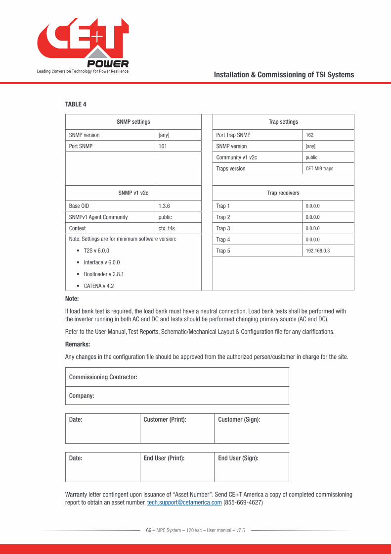
TABLE 4
SNMP settings Trap settings
SNMP version [any] Port Trap SNMP 162
Port SNMP 161 SNMP version [any]
Community v1 v2c public
Traps version CET MIB traps
SNMP v1 v2c Trap receivers
Base OID 1.3.6 Trap 1 0.0.0.0
SNMPv1 Agent Community public Trap 2 0.0.0.0
Context ctx_t4s Trap 3 0.0.0.0
Note: Settings are for minimum software version:
• T2S v 6.0.0
• Interface v 6.0.0
• Bootloader v 2.8.1
• CATENA v 4.2
Trap 4 0.0.0.0
Trap 5 192.168.0.3
Note:
If load bank test is required, the load bank must have a neutral connection. Load bank tests shall be performed with the inverter running in both AC and DC and tests should be performed changing primary source (AC and DC).
Refer to the User Manual, Test Reports, Schematic/Mechanical Layout & Configuration file for any clarifications.
Remarks:
Any changes in the configuration file should be approved from the authorized person/customer in charge for the site.
Commissioning Contractor:
Company:
Date: Customer (Print): Customer (Sign):
Date: End User (Print): End User (Sign):
Warranty letter contingent upon issuance of “Asset Number”. Send CE+T America a copy of completed commissioning report to obtain an asset number. [email protected] (855-669-4627)
66 – MPC System – 120 Vac – User manual – v7.5
Installation & Commissioning of TSI Systems
15. Troubleshooting
15.1 Trouble Shooting
Inverter module does not power up: Check AC input present and in range (AC breakers)
Check DC input present and in range (DC breakers)
Check that the inverter is properly inserted
Remove inverter to verify that slot is not damaged, check connectors
Check that module(s) is (are) in OFF state
Check for loose terminations
Inverter system does not start: Check that T2S is present and properly inserted
Check remote ON/OFF terminal
Check the configuration and setting
Check threshold level
Inverter only run on AC or DC: Check AC input present and in range (AC breakers)
Check DC input present and in range (DC breakers)
Check the configuration and setting
Check threshold level(s)
No output power: Check output breaker
All OK but I have alarm: Check configuration file and correct No of modules
Download/clear log file
No output alarm: Mind the default time delay (UA: 60s, NUA: 30s)
Check configuration file
No information on CanDis: Check that T2S is present and properly inserted
Check that the RJ45 cable is connected between T2S shelf and CanDis shelf
No value on TCP/IP: Check that the RJ45 cable is connected between T2S shelf and CanDis shelf
Wait approx 2 minutes to allow the system to collect serial data.
67 – MPC System – 120 Vac – User manual – v7.5
Troubleshooting

15.2 Defective modulesUnless input power is down all LEDs on each module should be green (see section 9, page 35). No light, orange light , red or flashing light are abnormal conditions. Refer to section 10.1.2, page 43 to collect and record module information. If no fix can be found, replace module.
15.2.1 Replacing modules
Refer to section 11, page 53 to remove and re-insert modules.
15.2.2 Return defective T2S interface
A T2S with LEDs that are off or cannot interface with your laptop is the indication that T2S could be defective. Proceed as per section 15.2.4, page 68.
15.2.3 Return defective shelf
The shelf is passive. Failure is unlikely to happen. In turn defective situation are barely always visible. After depose proceed as per section 15.2.4, page 68.
15.2.4 Return defective modules
• A repair request should follow the regular logistics chain: End-user => Distributor => CE+T Power.
• Before returning a defective product, a RMA number must be requested through the http://my.cet-power.com extranet. Repair registering guidelines may be requested by email at [email protected].
• The RMA number should be mentioned on all shipping documents related to the repair.
• Be aware that products shipped back to CE+T Power without being registered first will not be treated with high priority!
• Information on failure occurrence as well as module status given through Menu 2-1 shall be attached to defective unit return package or recorded in RMA.
68 – MPC System – 120 Vac – User manual – v7.5
Troubleshooting
16. ServiceFor Service
• Check Service Level Agreement (SLA) of your vendor. Most of the time they provide assistance on call with integrated service. If such SLA is in place, you must call their assistance first.
• If your vendor doesn’t provide such assistance (*) you may call CE+T directly. Toll free Number 1(855) 669 - 4627(**)
Service is available from 8:00 A.M. to 10:00 P.M. EST, Monday through Friday, except closing periods for holidays or inclement weather.
Major Incidents and Emergency conditions can be invoked for immediate handling of same number or by dropping a mail on [email protected] (***)
(*) CE+T will redirect your call to your vendor if he has such SLA in place.
(**) Valid in USA and Canada only.
(***) Messages that are not Major Incident or Emergency will be served at the next scheduled working day.
69 – MPC System – 120 Vac – User manual – v7.5
Service

17. Preventive MaintenanceAs maintenance will be performed on live system, all tasks should be performed only by trained personnel with sufficient knowledge on TSI product.
Tasks :
• Identify the site, customer, rack number, product type.
• Download and save configuration file for back up.
• Check configuration file to be in accordance with operational site conditions.
• Read and save log file for back up.
• Check and analyze log file, and if alarm are present.
• Replace dust filter if present. Filter is mandatory in dusty environment.
• Check module temperature and log value. If internal temperature is higher then previous year, it should be interesting analyze if it is due an increasing load or dust effect. It is common to have a delta of 15°C by 30% of load between the ambient and the internal temperature. If temperature increase due internal dust, clean the module by air suction blower or vacuum cleaner.
• Clean system (vacuum cleaner or dry cloth)
• Control the inverter mapping (AC Group, DC Group, Address)
• Check load level and record the rate value (print in word document the 4 screen modules information for the 32 modules, the 3 screen for the phases value and the 2 screens for the group AC and DC value)
• Change the configuration file for AC and DC mix mode to check that all TSI work on both power supply
• Check alarm operation (e.g., redundancy lost, mains failure, DC failure) on dry contact and through SNMP system or web interface.
• Switch OFF AC IN and check alarms.
• Check temperature terminal and temperature wiring. If possible use an infrared camera.
• Read and record value as wave form, power factor, Crest factor, THD I from power analyzer.
• Take system picture
• Keep track of report and provide end user with a copy.
• Perform a MBP procedure. This task is not really recommended*, but could be demanded by site manager.
* It is not recommended because when you perform a By-pass procedure, generally there is no back up on AC input line, and the load could be dropped if there is a loss of AC power.
70 – MPC System – 120 Vac – User manual – v7.5
Preventive Maintenance
