mpeg-5 essential video coding (evc) · 9 coding structure •the coding structure in this section...
TRANSCRIPT
MPEG-5 Essential Video Coding (EVC)
Presented by Ken McCannChairman of MPEG Ad hoc Group on EVC
1
Background
EVC Baseline profile
EVC Main profile
Testing results
Contents

Background
2

3
Coding efficiency improves with every new generation of video coding standard, but this is not the only factor that determines the industry choice of codec• MPEG-5 Essential Video Coding (EVC) aims to address use cases that are currently not well
served by other MPEG and ITU-T standards
EVC uses a new way to create video coding standards• Designed to meet both business and technical requirements
• While remaining consistent with ITU-T/ITU-R/ISO/IEC common patent policy
Overall goals for EVC• Encourage the timely publication of licensing terms to allow reliable business plans to be created
• Coding efficiency at least as good as HEVC
• Complexity suitable for practical real time encoding
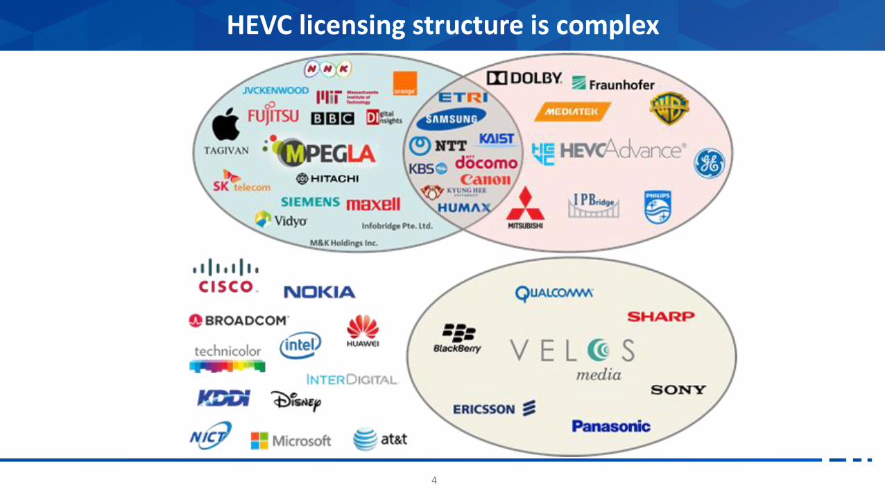
Motivated by observing that the complex licensing structure for HEVC has resulted in only limited adoption in some market segments
Background
4
HEVC licensing structure is complex

5
Baseline profile• Includes only technologies that are more than 20 years old or that were submitted with
a royalty-free declaration
Main profile • Adds a small number of additional tools that each provide a significant improvement in
terms of compression performance
• Each additional Main profile tool is isolated so that it can be switched off independently of other tools with limited loss of performance
• Contributors were encouraged to submit voluntary declarations on the timely publication of licensing terms
EVC uses a novel profile structure
XXX company may have current or pending patent rights relating to the technology described in this contribution and,conditioned on reciprocity, is prepared to grant licenses under reasonable and non-discriminatory terms as necessaryfor implementation of the resulting ITU-T Recommendation | ISO/IEC International Standard. Furthermore, XXXcompany is prepared to make the timely publication of applicable licensing terms within 2 years of FDIS stageeither individually or as part of a patent pool.
6
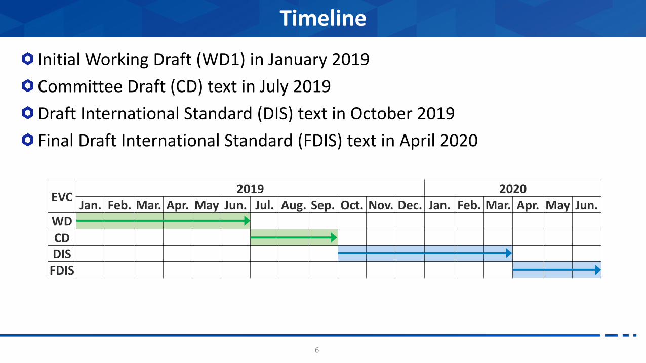
Initial Working Draft (WD1) in January 2019
Committee Draft (CD) text in July 2019
Draft International Standard (DIS) text in October 2019
Final Draft International Standard (FDIS) text in April 2020
Timeline
EVC2019 2020
Jan. Feb. Mar. Apr. May Jun. Jul. Aug. Sep. Oct. Nov. Dec. Jan. Feb. Mar. Apr. May Jun.WDCDDIS
FDIS
7
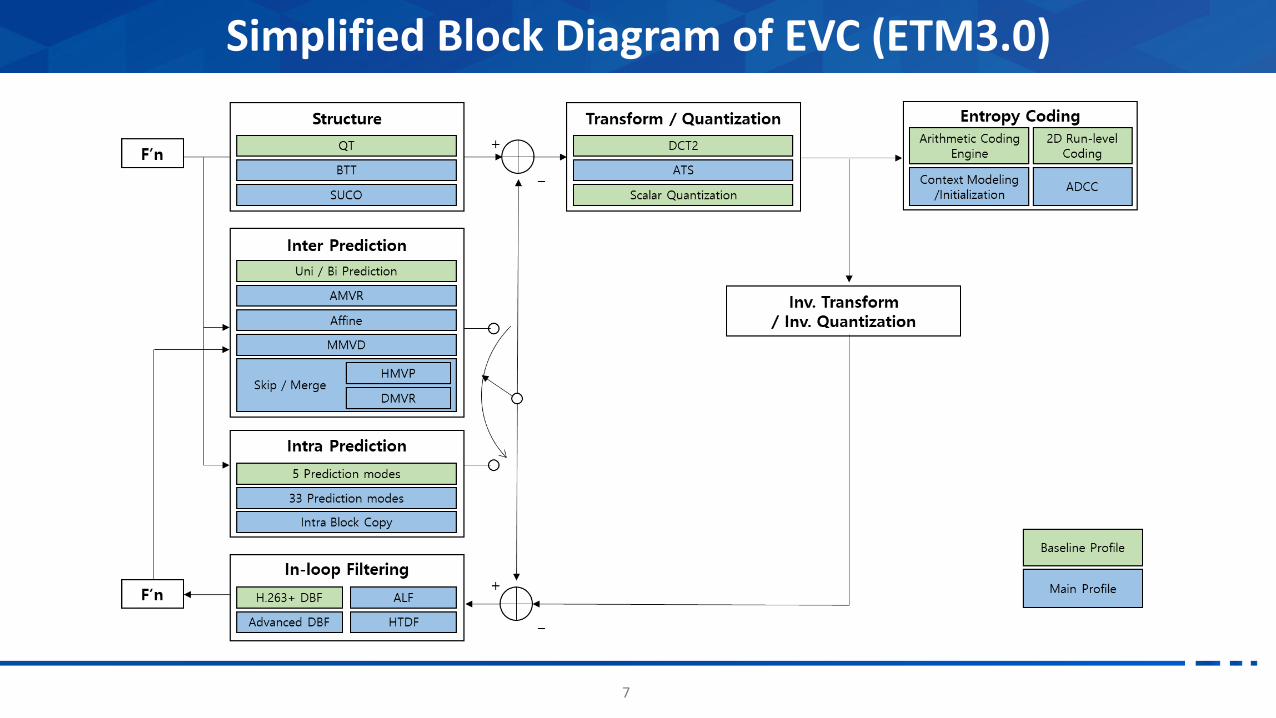
Simplified Block Diagram of EVC (ETM3.0)

Tool set of Baseline profile
8

9
Coding structure• The coding structure in this section employed a quad-tree based coding structure
which can use blocks up to 64x64. The quad-tree based coding algorithm was introduced in the early 1990s and an efficient splitting method was disclosed in 1994
• Prior art: G.J. Sullivan and R.L. Baker Efficient quadtree coding of images and video, IEEE Transactions on Image Processing pp327-331, May 1994.
Intra prediction• 5 directional prediction modes are employed; DC, horizontal (H), vertical (V), diagonal
left (DL), diagonal right (DR). A codeword for prediction mode of the current block is adaptively assigned by using a mapping table between symbol and prediction mode which is selected based on the prediction modes of neighbouring upper and left blocks.
• Prior art: G. Bjontegaard, “Response to call for proposals for H.26L”, ITU-T SG16 Doc.Q15-F-11, Q15-F-11, Nov. 1998
Baseline profile

10
Normal inter prediction• Inter prediction using uni-directional block-based motion compensation and Bi-directional
prediction in the MPEG-2 standard.
• Temporal direct mode using the motion vector of the temporally co-located block in H.263.
• Three neighbouring motion vectors and a motion vector of temporally co-located blocks
• Prior art: M.C. Chen and A. Willson, A Spatial and Temporal Motion Vector Coding Algorithm for Low-Bit-Rate Video Coding, International Conference on Image Processing, Oct. 1997
Modes for Inter prediction • Using motion vectors of neighbouring blocks as candidates for the motion vector for the
current block was introduced in the 1980s
• The competition based motion vector coding method was proposed in 1999
• Prior art: S.D. Kim, and J.B. Ra, An efficient motion vector coding scheme based on minimum bitrate prediction, IEEE Transaction on Image Processing, vol.8, no.8, Aug. 1999.
Baseline profile
11
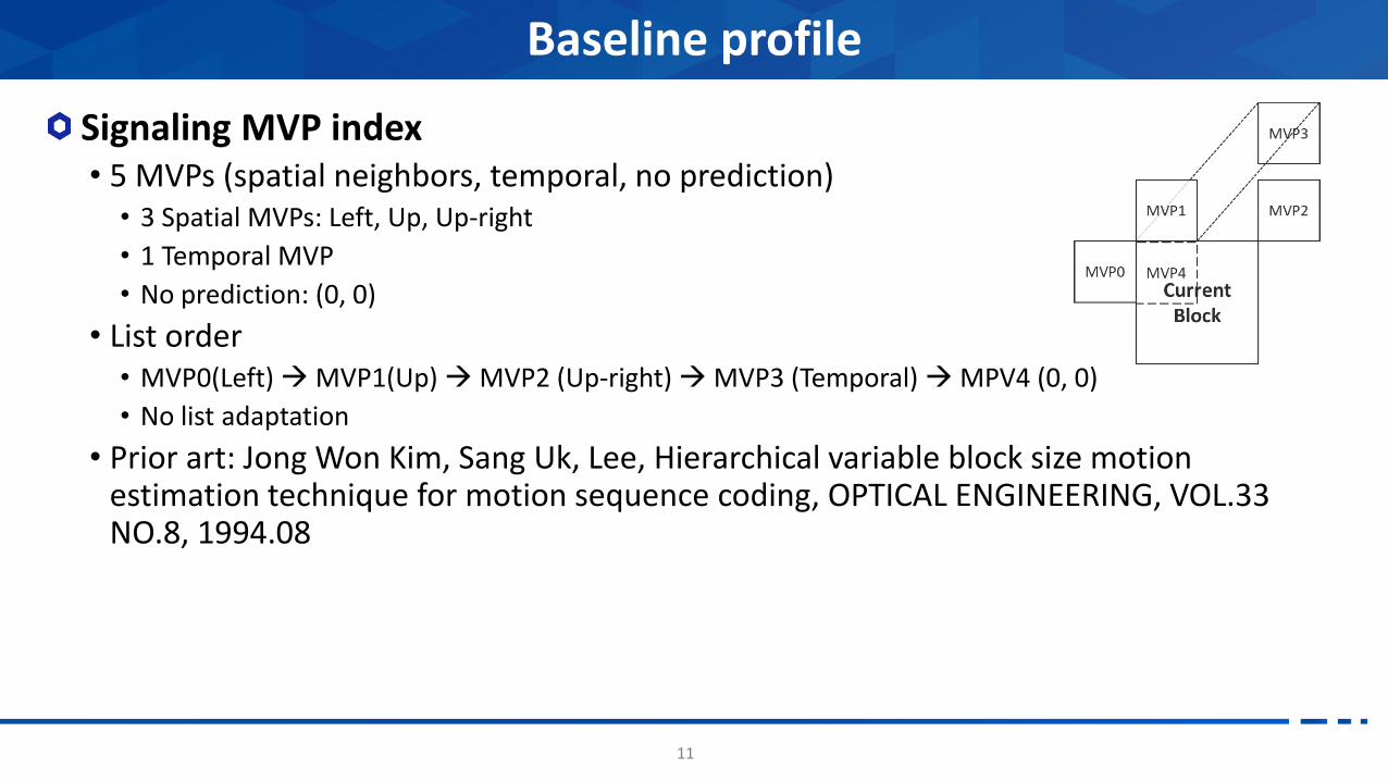
Signaling MVP index• 5 MVPs (spatial neighbors, temporal, no prediction) • 3 Spatial MVPs: Left, Up, Up-right
• 1 Temporal MVP
• No prediction: (0, 0)
• List order• MVP0(Left) MVP1(Up) MVP2 (Up-right) MVP3 (Temporal) MPV4 (0, 0)
• No list adaptation
• Prior art: Jong Won Kim, Sang Uk, Lee, Hierarchical variable block size motion estimation technique for motion sequence coding, OPTICAL ENGINEERING, VOL.33 NO.8, 1994.08
Baseline profile

12
½ & ¼-Pel interpolation• 2D separable filter based on wiener based 8-tap filter for luma , 4-tap filter for chroma
component
• Fractional sample interpolation (Quarter-pel interpolation) was introduced at 1996.
Using multiple reference pictures • The usage of multiple reference frames was introduced at 1996.
• Prior art: Multiframe Block Motion Compensated Video Coding for Wireless Channels][M. Budagavi]
Baseline profile
13
Transform and quantization • A discrete cosine transform (DCT) is applied to a residual block between an original
block and the corresponding prediction block.
• The transform size is equal to the coding block size, i.e. from 2x2 to 64x64.
• The range of the quantization parameter (QP) is from 0 to 51 and a scaling factor (SF) corresponding to each QP is defined by a look-up table.
• Prior art: K.R. Rao and P. Yip, Discrete Cosine Transform Algorithms, Advantage, Applications, New York Academic, 1990.
• Prior art: G. Bjontegaard, “Response to call for proposals for H.26L”, ITU-T SG16 Doc.Q15-F-11, Q15-F-11, Nov. 1998
Baseline profile
14
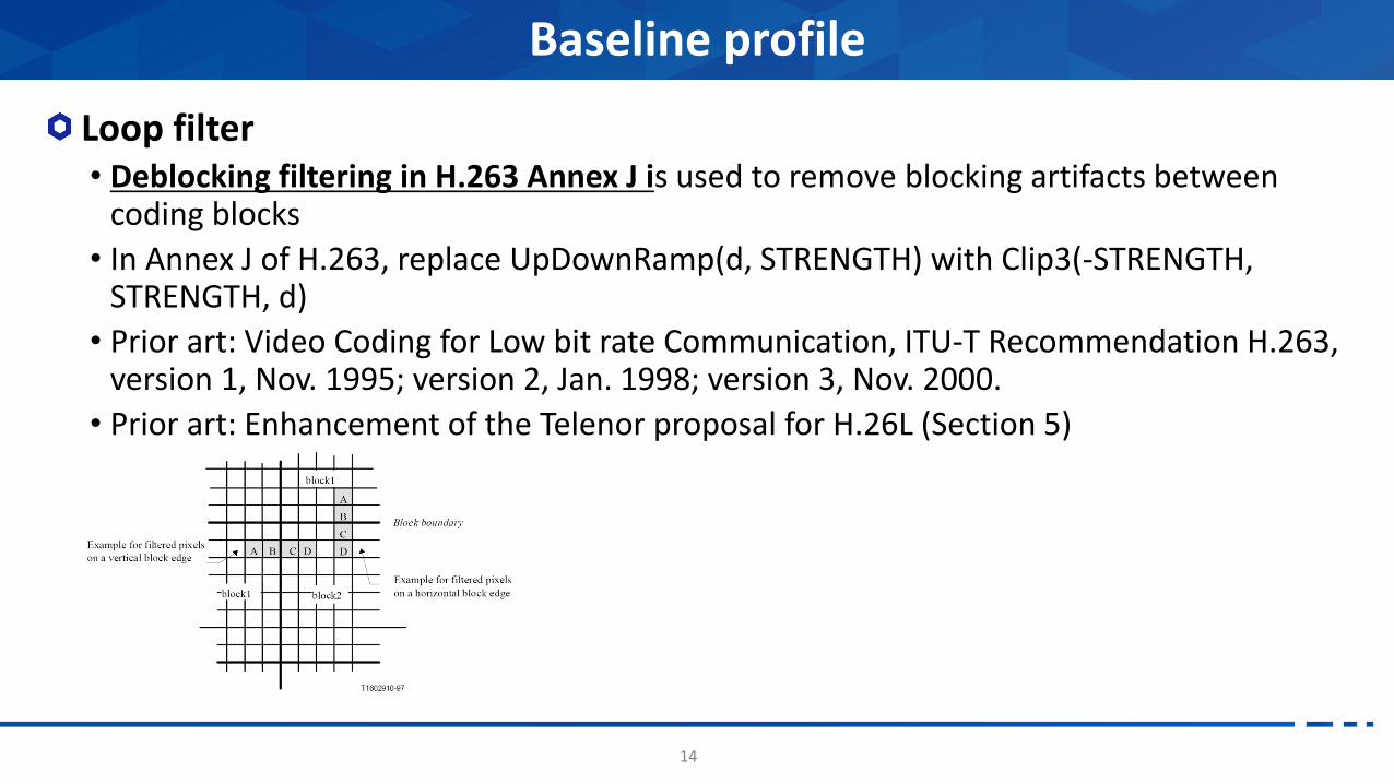
Loop filter• Deblocking filtering in H.263 Annex J is used to remove blocking artifacts between
coding blocks
• In Annex J of H.263, replace UpDownRamp(d, STRENGTH) with Clip3(-STRENGTH, STRENGTH, d)
• Prior art: Video Coding for Low bit rate Communication, ITU-T Recommendation H.263, version 1, Nov. 1995; version 2, Jan. 1998; version 3, Nov. 2000.
• Prior art: Enhancement of the Telenor proposal for H.26L (Section 5)
Baseline profile
15
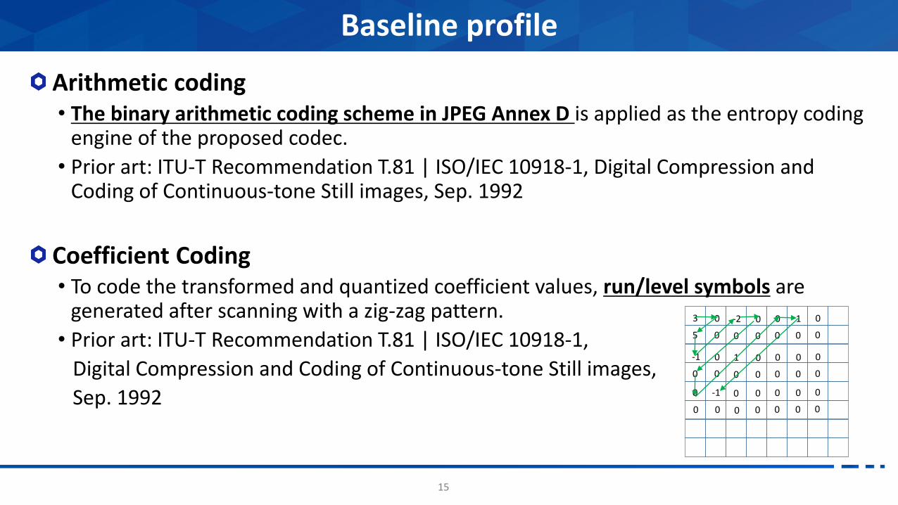
Arithmetic coding• The binary arithmetic coding scheme in JPEG Annex D is applied as the entropy coding
engine of the proposed codec.
• Prior art: ITU-T Recommendation T.81 | ISO/IEC 10918-1, Digital Compression and Coding of Continuous-tone Still images, Sep. 1992
Coefficient Coding• To code the transformed and quantized coefficient values, run/level symbols are
generated after scanning with a zig-zag pattern.
• Prior art: ITU-T Recommendation T.81 | ISO/IEC 10918-1,
Digital Compression and Coding of Continuous-tone Still images,
Sep. 1992
Baseline profile
3 0
5 0
-2 0
0 0
-1 0
0 0
1 0
0 0
0
0
0
0
1
0
0
0
0
0
0
0
0
0
0
0
0
0
0
0
0 -1 0
0 0 0

Tool set of Main profile
16

17
Binary and triple tree (BTT)• Binary and triple three splitting from the maximum CTU size
• Split shapes of BTT• BTT uses Bi-split and Tri-split with vertical or horizontal direction
• Configure of BTT• According to a configuration, allowed split modes and bits assignment are defined
Main profile: Block Partitioning
Current CU
64x64
32x64
BI_VER_SPLIT
32x64 32x64
16x64 16x64
64x32
32x32
64x32
32x32
32x6416x64 16x64
16x648x64 8x64
64x32
32x32
64x16
64x16
32x16
32x16
Allowed shape
Not allowed shape
BI_HOR_SPLIT TRI_VER_SPLIT TRI_HOR_SPLIT
Split configurelog2_cu_12_ratio_max_minus2=4 (real size is 64) log2_cu_14_ratio_max_minus2=3 (real size is 32) log2_tri_split_max_minus2=4 (real size is 64)
BI_VER_SPLIT BI_HOR_SPLIT TRI_VER_SPLIT TRI_HOR_SPLIT
b0
BI_VER_SPLIT
BI_HOR_SPLIT
TRI_VER_SPLIT
TRI_HOR_SPLIT
allowed
O
O
X
X
b1 b2
NO_SPLIT O 0
1 1
1 0
b0
BI_VER_SPLIT
BI_HOR_SPLIT
TRI_VER_SPLIT
TRI_HOR_SPLIT
allowed
O
O
X
O
b1 b2
NO_SPLIT O 0
1 1
1 0 0
1 0 1
b0
BI_VER_SPLIT
BI_HOR_SPLIT
TRI_VER_SPLIT
TRI_HOR_SPLIT
allowed
O
O
O
X
b1 b2
NO_SPLIT O 0
1 1 0
1 0
1 1 1
b0
BI_VER_SPLIT
BI_HOR_SPLIT
TRI_VER_SPLIT
TRI_HOR_SPLIT
allowed
O
O
O
O
b1 b2
NO_SPLIT O 0
1 0 1
1 0 0
1 1 1
1 1 0
b0
BI_VER_SPLIT
BI_HOR_SPLIT
TRI_VER_SPLIT
TRI_HOR_SPLIT
allowed
O
X
O
X
b1 b2
NO_SPLIT O 0
1 0
1 1
b0
BI_VER_SPLIT
BI_HOR_SPLIT
TRI_VER_SPLIT
TRI_HOR_SPLIT
allowed
X
O
X
O
b1 b2
NO_SPLIT O 0
1 0
1 1
b0
BI_VER_SPLIT
BI_HOR_SPLIT
TRI_VER_SPLIT
TRI_HOR_SPLIT
allowed
O
X
X
X
b1 b2
NO_SPLIT O 0
1
b0
BI_VER_SPLIT
BI_HOR_SPLIT
TRI_VER_SPLIT
TRI_HOR_SPLIT
allowed
X
O
X
X
b1 b2
NO_SPLIT O 0
1
Number of split modes 4 Number of split modes 2
Number of split modes 3 Number of split modes 1
Example of allowed split modes Example of bits assignment

18
Split Unit Coding Order (SUCO)• Signaling of child tree coding order for each vertical split
• 1 flag for each vertical split (SPLIT_BI_VER, SPLIT_TR_VER, SPLIT_QT)
• Same direction for above two and bottom two for SPLIT_QT
• Applied depth
• MIN_SUCO_DEPTH: min(log2_width, log2_height)
• MAX_SUCO_DEPTH: max(log2_width, log2_height)
• Intra/Inter prediction modification according to Left/Right availability
• LR_10, LR_01, LR_11, LR_00
Main profile: Block coding order
CodedUn-coded
Split Unit BT
TT
QT
L2R
R2L
Split (QT/BT/TT)
Intra reference pixels Inter MVP position
19
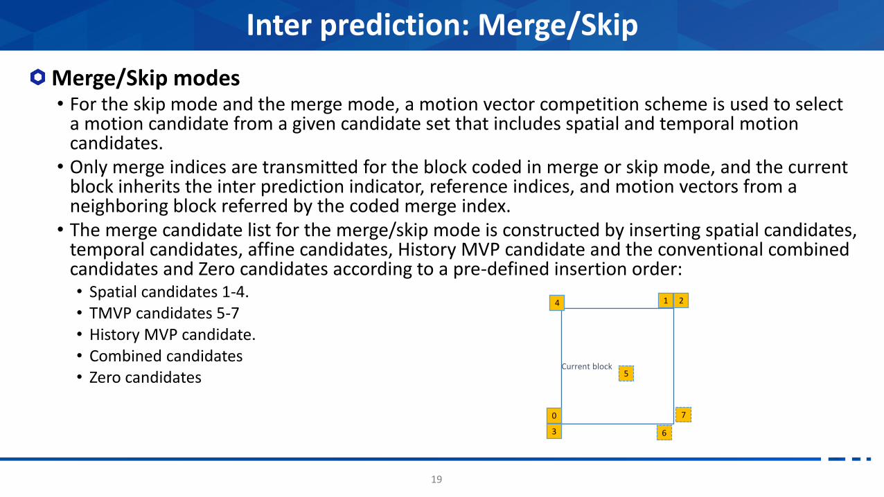
Merge/Skip modes• For the skip mode and the merge mode, a motion vector competition scheme is used to select
a motion candidate from a given candidate set that includes spatial and temporal motion candidates.
• Only merge indices are transmitted for the block coded in merge or skip mode, and the current block inherits the inter prediction indicator, reference indices, and motion vectors from a neighboring block referred by the coded merge index.
• The merge candidate list for the merge/skip mode is constructed by inserting spatial candidates, temporal candidates, affine candidates, History MVP candidate and the conventional combined candidates and Zero candidates according to a pre-defined insertion order: • Spatial candidates 1-4.• TMVP candidates 5-7• History MVP candidate.• Combined candidates• Zero candidates
Inter prediction: Merge/Skip
Current block
7
6
4
0
3
1 2
5

20
AMVR ( Adaptive Motion Vector Resolution )• MVR ( Motion Vector Resolution ) competition including super MVR
• ¼, ½, 1, 2, 4
• MVR is applied on MVP and MVD.
• Coupling of MVR and MVP index
• Different MVP for the different MVR
• More accurate MVP in fine MVR and less accurate in coarse MVR
• Fixed one MVP for each MVR, based on the hit-ratio of each MVP
Inter prediction: AMVR
MVP precision MVR, MVP, SR

21
MMVD (Merge with Motion Vector Difference)• Simplified MV expression method based on statistical MVD modeling
• 3 components ( starting point, motion magnitude, motion direction )
• High probability points around MV of skip-candidate list are considered.
• Starting point : [0~N] (N : MAX number of skip candidate)
• Motion magnitude : [ ¼, ½, 1, 2, 4, 8, 16, 32 ]
• Motion direction : 4 directions (+,0),(-,0),(0,+),(0,-)
• Prediction directions ( Bi, Uni0, Uni1 ) of base candidate are all considered.
Inter prediction: MMVD
Search points based on MVD’s statistical information
UMVE search process

22
Affine• AF_INTER: model is adaptively selected in block level• 4-parameters model, represented by two motion vectors (top-
left and top-right corner) of a CU
• 6-parameters model, represented by three motion vectors (top-left, top-right and bottom-left corner) of a CU
• Extrapolated affine MVPs similar to affine merge are inserted into beginning of MVP list
• AF_MERGE: up to 5 candidates• Extrapolated affine candidates from neighbor coded affine
block, with the order: F, D, E, G, A
• Construct several new affine models from the motion vectors of spatial and temporal neighbor blocks
Inter prediction: Affine

23
Decoder Side Motion Vector Refinement (DMVR)
Inter prediction: DMVR
MV0
MV1
MV1'
MV0'
Current blockReference block in list0 Reference block in list1
• Process invoke• Bi-predicted in skip or direct merge mode
• Integer MV offset search, with fractional pel MV offset derived by error surface
• Search range set as 2 samples to reduce memory access.
• Mean-removal SAD is used as matching cost
• Sub-CU 16x16 for large CU size

24
History based MVP (HMVP)• History-based Motion Vector Prediction (HMVP) method is a inter coding tool which can be applied to
both merge candidate list and Advanced motion vector prediction (AMVP) candidate list construction process.
• In HMVP, a table of HMVP candidates is maintained and updated on-the-fly. Whenever a non-affine inter coded block is decoded, the decoded motion information is used to update the HMVP table in the last position following a First-In-First-Out (FIFO) rule to remove and add entry.
• Subsampling-based HMVP fetching, ratio 1:4
• HMVP candidate inserted following the TMVP for merge and following SMVP for AMVP
Inter prediction: HMVP
Load a table with HMVP candidatesDecode a block with HMVP
candidates
Update the table with decoded
motion information

25
Adaptive Loop Filter architecture:• Design similar to that in VVC• Filter support:
• Diamond shape• Up-to 7x7 filter support
• Classification:• 25 classes• 4x4 block bases classifier
• CTB-level flexibility• Set of fixed filters
• 64 filters• Size of 7x7
• Adaptation Parameter Set (APS) • Reusage of the ALF coefficients signaled in APS NAL units• An identification index syntax element signaled in the slice header• APS buffer size up to 32 entries
Loop Filtering: Adaptive Loop Filter
Filter Support
c0
c2c1 c3
c4 c5 c6 c5 c4
c2c3 c1
c0
c0
c2c1 c3
c4 c5 c6 c7 c8
c10 c11 c12 c11 c10 c9c9
c8 c7 c6 c5 c4
c2c3 c1
c0
26
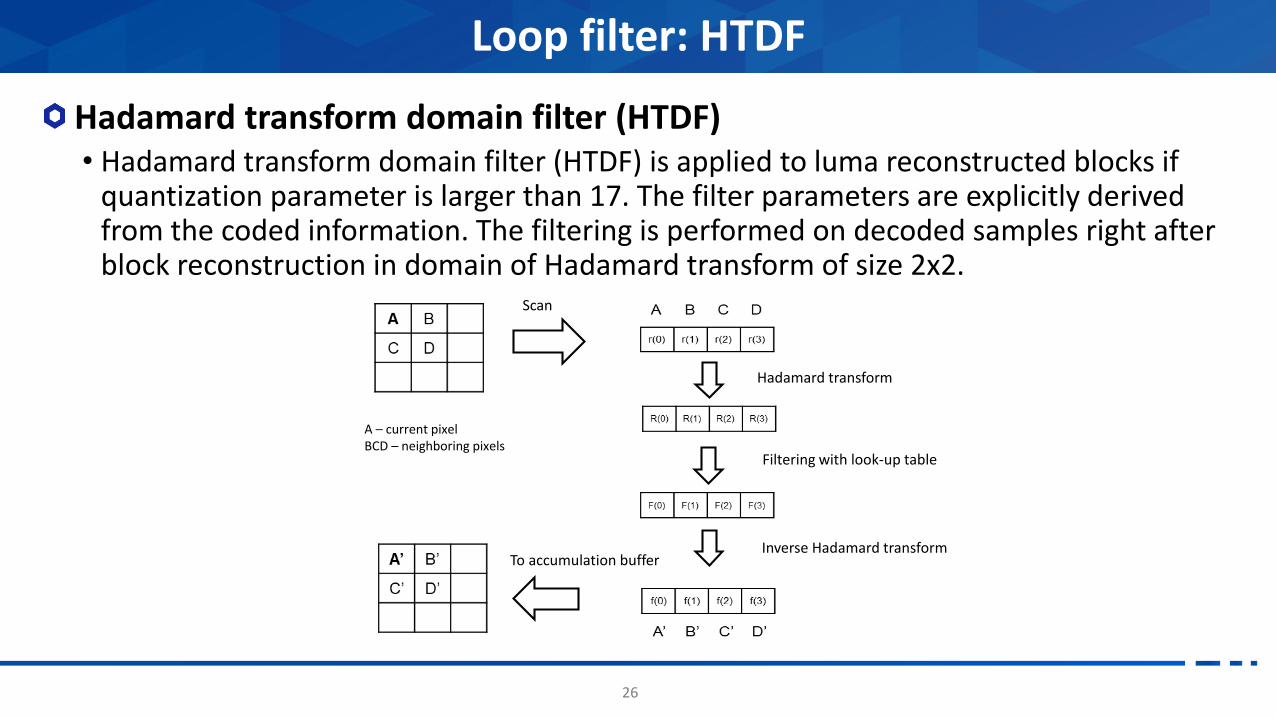
Hadamard transform domain filter (HTDF)• Hadamard transform domain filter (HTDF) is applied to luma reconstructed blocks if
quantization parameter is larger than 17. The filter parameters are explicitly derived from the coded information. The filtering is performed on decoded samples right after block reconstruction in domain of Hadamard transform of size 2x2.
Loop filter: HTDF
Scan
Hadamard transform
Filtering with look-up table
Inverse Hadamard transformTo accumulation buffer
A – current pixelBCD – neighboring pixels

27
Key elements:• Zig-zag scan in inverse order + Last X/Y signaling;• Chunk transform coefs processing (size of 16);• Bit-planes context coding;• Escape to bypass (8 flagA or 1 flagB).
Signaling:• Context coded (number of contexts):
• Last X/Y 56• Significant flag: 47• LevelA & B flag: 18• Dependency on causal neighbors (up-to 5).
• TR+Golomb: RemainLevel.• FLC: Sign Flag
Advanced coefficient coding
-3 0
5 0
-2 0
0 0
-1 0
0 0
1 0
0 0
0
0
0
0
1
0
0
0
0
0
0
0
0
0
0
0
0
0
0
0
0 -1 0
0 0 0
(lastX, lastY)
GtA: 0 0 0 1 0 1
Chunk(16)lastXY: [1, 4]
Chunk
Sigflag: 1, 0, 0, 0, 1, 0, 0, 1, 0, 0, 0, 0, 0, 0, 1, 0, 1, 1, 0, 1
GtB: 0 1
RemLevel: 2 2
Sign: 1 0 0 1 1 0 1
Data: -1, 0, 0, 0, 1, 0, 0, 1, 0, 0, 0, 0, 0, 0, -1, 0, 1, 5, 0, -3

28
Intra block• CU level on/off decision• Applied block size: Upto 32x32
• DCT2 vs ATS
• 1 flag for the use of ATS based on RDO evaluation
• Kernel selection• 2 flags for used kernels of vertical and horizontal directions
Inter block• TU may be smaller than the CU, and the
TU shape & position info is signaled• Two TU shapes & Two TU positions• Position dependent core transform:
DCT-8 for pos 0, DST-7 for pos 1
Adaptive transform selection (ATS)

29
Intra block copy in main profile• 128x128 reconstructed samples from the neighboring left CTU can be used as IBC
reference purpose.
• Once any of the 64x64 unit reference sample memory in a 128x128 CTU begins to update with the reconstructed samples from the current CU, the previous stored reference samples in the whole 64x64 unit become unavailable for IBC reference purpose.
• IBC mode (IBC flag) is signaled in a CU level. The IBC mode is considered as a prediction mode other than intra and inter prediction modes. The is no need to include current picture as one of the reference pictures in the reference picture list 0. The motion vector of IBC is derived in integer pixel.
• The coding of block vector (BV) is straightforward without using prediction. The coding engine reuses the one used in mvd coding. The BV considered is in integer resolution.
• The maximum allowed block size for IBC mode is signaled in the SPS level.
Intra Block Copy

Testing results
30

31
Testing condition• EVC Baseline profile, ETM3.0
• Anchor: H.264/AVC (JM19.0)
Coding performance
Coding performance of EVC Baseline profile
Over JM19.0 (Random Access) Over JM19.0 (Low Delay)
Y U V EncT DecT Y U V EncT DecT
Class A -38.0% -33.7% -38.4% 46% 117%
Class B -24.8% -27.8% -26.9% 39% 114% -25.4% -21.4% -21.5% 24% 122%
Class E -30.9% -34.0% -34.9% 25% 163%
Overall -31.4% -30.8% -32.7% 42% 116% -27.5% -26.1% -26.5% 24% 136%

32
Testing condition• EVC Main profile, ETM3.0
• Anchor: HEVC (HM16.6)
Coding performance
Coding performance of EVC Main profile
Over HM16.6 (Random Access) Over HM16.6 (Low Delay)
Y U V EncT DecT Y U V EncT DecT
Class A -30.0% -27.4% -26.7% 413% 167%
Class B -23.1% -23.8% -21.2% 491% 142% -17.5% -13.7% -11.0% 627% 127%
Class E -15.1% -9.5% -11.7% 283% 108%
Overall -26.5% -25.6% -23.9% 450% 154% -16.6% -12.1% -11.3% 465% 119%

33
EVC Baseline profile
H.264/AVC11.0Mbps
EVC 6.5Mbps

34
EVC Main profile
EVC 3.8Mbps
HEVC6.5Mbps

35
Thank you!
With special thanks to all AhG members who contributed to this work, especially Kiho Choi who created many of these slides