mpls layer 3 vpns configuration guide, cisco ios release … · prerequisites for directing mpls...
TRANSCRIPT

MPLS Layer 3 VPNs Configuration Guide,Cisco IOS Release 12.4
Americas HeadquartersCisco Systems, Inc.170 West Tasman DriveSan Jose, CA 95134-1706USAhttp://www.cisco.comTel: 408 526-4000 800 553-NETS (6387)Fax: 408 527-0883

THE SPECIFICATIONS AND INFORMATION REGARDING THE PRODUCTS IN THIS MANUAL ARE SUBJECT TO CHANGE WITHOUT NOTICE. ALL STATEMENTS,INFORMATION, AND RECOMMENDATIONS IN THIS MANUAL ARE BELIEVED TO BE ACCURATE BUT ARE PRESENTED WITHOUT WARRANTY OF ANY KIND,EXPRESS OR IMPLIED. USERS MUST TAKE FULL RESPONSIBILITY FOR THEIR APPLICATION OF ANY PRODUCTS.
THE SOFTWARE LICENSE AND LIMITED WARRANTY FOR THE ACCOMPANYING PRODUCT ARE SET FORTH IN THE INFORMATION PACKET THAT SHIPPEDWITH THE PRODUCT AND ARE INCORPORATED HEREIN BY THIS REFERENCE. IF YOU ARE UNABLE TO LOCATE THE SOFTWARE LICENSE OR LIMITEDWARRANTY, CONTACT YOUR CISCO REPRESENTATIVE FOR A COPY.
The Cisco implementation of TCP header compression is an adaptation of a program developed by the University of California, Berkeley (UCB) as part of UCB’s public domain versionof the UNIX operating system. All rights reserved. Copyright © 1981, Regents of the University of California.
NOTWITHSTANDING ANY OTHER WARRANTY HEREIN, ALL DOCUMENT FILES AND SOFTWARE OF THESE SUPPLIERS ARE PROVIDED “AS IS” WITH ALLFAULTS. CISCO AND THE ABOVE-NAMED SUPPLIERS DISCLAIM ALL WARRANTIES, EXPRESSED OR IMPLIED, INCLUDING, WITHOUT LIMITATION, THOSE OFMERCHANTABILITY, FITNESS FOR A PARTICULAR PURPOSE AND NONINFRINGEMENT OR ARISING FROM A COURSE OF DEALING, USAGE, OR TRADEPRACTICE.
IN NO EVENT SHALL CISCO OR ITS SUPPLIERS BE LIABLE FOR ANY INDIRECT, SPECIAL, CONSEQUENTIAL, OR INCIDENTAL DAMAGES, INCLUDING,WITHOUT LIMITATION, LOST PROFITS OR LOSS OR DAMAGE TO DATA ARISING OUT OF THE USE OR INABILITY TO USE THIS MANUAL, EVEN IF CISCO ORITS SUPPLIERS HAVE BEEN ADVISED OF THE POSSIBILITY OF SUCH DAMAGES.
Cisco and the Cisco logo are trademarks or registered trademarks of Cisco and/or its affiliates in the U.S. and other countries. To view a list of Cisco trademarks, go to this URL: www.cisco.com/go/trademarks. Third-party trademarks mentioned are the property of their respective owners. The use of the word partner does not imply a partnership relationshipbetween Cisco and any other company. (1110R)
Any Internet Protocol (IP) addresses and phone numbers used in this document are not intended to be actual addresses and phone numbers. Any examples, command display output,network topology diagrams, and other figures included in the document are shown for illustrative purposes only. Any use of actual IP addresses or phone numbers in illustrative contentis unintentional and coincidental.
© 2011 Cisco Systems, Inc. All rights reserved.

C O N T E N T S
Configuring MPLS Layer 3 VPNs 1
Finding Feature Information 1
Prerequisites for MPLS Layer 3 VPNs 1
Restrictions for MPLS Layer 3 VPNs 2
Information About MPLS Layer 3 VPNs 3
MPLS VPN Definition 4
How an MPLS VPN Works 5
How Virtual Routing and Forwarding Tables Work in an MPLS VPN 5
How VPN Routing Information Is Distributed in an MPLS VPN 5
BGP Distribution of VPN Routing Information 6
MPLS Forwarding 6
Major Components of MPLS VPNs 6
Benefits of an MPLS VPN 7
How to Configure MPLS Layer 3 VPNs 9
Configuring the Core Network 9
Assessing the Needs of MPLS VPN Customers 9
Configuring Routing Protocols in the Core 10
Configuring MPLS in the Core 10
Configuring Multiprotocol BGP on the PE Routers and Route Reflectors 10
Troubleshooting Tips 12
Connecting the MPLS VPN Customers 12
Defining VRFs on the PE Routers to Enable Customer Connectivity 12
Configuring VRF Interfaces on PE Routers for Each VPN Customer 14
Configuring Routing Protocols Between the PE and CE Routers 15
Configuring BGP as the Routing Protocol Between the PE and CE Routers 15
Configuring RIPv2 as the Routing Protocol Between the PE and CE Routers 17
Configuring Static Routes Between the PE and CE Routers 19
Configuring OSPF as the Routing Protocol Between the PE and CE Routers 21
Configuring EIGRP as the Routing Protocol Between the PE and CE Routers 23
MPLS Layer 3 VPNs Configuration Guide, Cisco IOS Release 12.4 iii

Configuring EIGRP Redistribution in the MPLS VPN 26
Verifying the VPN Configuration 28
Verifying Connectivity Between MPLS VPN Sites 29
Verifying IP Connectivity from CE Router to CE Router Across the MPLS Core 29
Verifying that the Local and Remote CE Routers Are in the Routing Table 30
Configuration Examples for MPLS VPNs 30
Configuring an MPLS VPN Using BGP Example 30
Configuring an MPLS VPN Using RIP Example 31
Configuring an MPLS VPN Using Static Routes Example 32
Configuring an MPLS VPN Using OSPF Example 33
Configuring an MPLS VPN Using EIGRP Example 34
Additional References 35
Feature Information for MPLS Layer 3 VPNs 37
Configuring Route Maps to Control the Distribution of MPLS Labels Between Routers in an
MPLS VPN 39
Finding Feature Information 39
Restrictions for Using Route Maps with MPLS VPNs 39
Prerequisites for Using Route Maps with MPLS VPNs 39
Information About Route Maps in MPLS VPNs 40
How to Configure Route Maps in an MPLS VPN 40
Configuring a Route Map for Incoming Routes 40
Configuring a Route Map for Outgoing Routes 42
Applying the Route Maps to the MPLS VPN Edge Routers 44
Troubleshooting Tips 46
Configuration Examples for Route Maps in MPLS VPNs 46
Using a Route Map in an MPLS VPN Inter-AS Network Example 46
Using a Route Map in an MPLS VPN CSC Network Example 47
Additional References 48
Feature Information for Route Maps in MPLS VPNs 50
Dialing to Destinations with the Same IP Address for MPLS VPNs 53
Finding Feature Information 53
Prerequisites for Dialing to Destinations with the Same IP Address for MPLS VPNs 53
Restrictions for Dialing to Destinations with the Same IP Address for MPLS VPNs 54
Information About Dialing to Destinations with the Same IP Address for MPLS VPNs 55
Introduction to Dialing to Destinations with the Same IP Address for MPLS VPNs 56
Contents
MPLS Layer 3 VPNs Configuration Guide, Cisco IOS Release 12.4iv

Benefits of this Feature 56
How to Enable Dialing to Destinations with the Same IP Address for MPLS VPNs 56
Mapping the VRF and Next-Hop Address to a Dial String 56
Verifying the Configuration 58
Troubleshooting Tips 58
Configuration Examples for Dialing to Destinations with the Same IP Address 59
Additional References 63
Feature Information for Dialing to Destinations with the Same IP Address 65
Ensuring MPLS VPN Clients Communicate over the Backbone Links 67
Finding Feature Information 67
Prerequisites for Ensuring MPLS VPN Clients Communicate over the Backbone Links 67
Restrictions for Ensuring MPLS VPN Clients Communicate over the Backbone Links 68
Information About Ensuring MPLS VPN Clients Communicate over the Backbone Links 68
Introduction to MPLS VPNs Using OSPF Between PE and CE Routers 68
OSPF Uses Backdoor Paths to Communicate Between VPN Sites 69
Sham-Links Direct Traffic Between VPN Sites over the MPLS VPN Backbone 70
How to Ensure That MPLS VPN Clients Communicate over the MPLS VPN Backbone 71
Configuration Examples for Ensuring MPLS VPN Clients Communicate over the MPLS VPN
Backbone 73
Additional References 76
Feature Information for Ensuring MPLS VPN Clients Communicate over the MPLS VPN
Backbone 77
Configuring Scalable Hub-and-Spoke MPLS VPNs 79
Finding Feature Information 79
Prerequisites for Configuring Scalable Hub-and-Spoke MPLS VPNs 79
Restrictions for Configuring Scalable Hub-and-Spoke MPLS VPNs 80
Information about Configuring Scalable Hub-and-Spoke MPLS VPNs 80
Overview 80
Upstream and Downstream VRFs 81
Reverse Path Forwarding Check 81
How to Ensure that MPLS VPN Clients Use the Hub PE Router 81
Configuring the Upstream and Downstream VRFs on the PE Router or the Spoke PE Router 81
Associating VRFs 83
Configuring the Downstream VRF for an AAA Server 84
Verifying the Configuration 84
Configuration Examples for Configuring Scalable Hub-and-Spoke MPLS VPNs 87
Contents
MPLS Layer 3 VPNs Configuration Guide, Cisco IOS Release 12.4 v

Configuring the Upstream and Downstream VRFs on the PE Router and the Spoke PE
Router Example 87
Associating VRFs Example 87
Configuring Scalable Hub-and-Spoke MPLS VPNs--Basic Configuration Example 88
Example 89
Additional References 90
Feature Information for Configuring Scalable Hub-and-Spoke MPLS VPNs 91
Assigning an ID Number to a VPN 93
Finding Feature Information 93
Information About VPN ID 93
Introduction to VPN ID 93
Components of the VPN ID 94
Management Applications That Use VPN IDs 94
Dynamic Host Configuration Protocol 94
Remote Authentication Dial-In User Service 94
How to Configure a VPN ID 95
Specifying a VPN ID 95
Restrictions 95
Verifying the VPN ID Configuration 96
Additional References 97
Feature Information for Assigning an ID Number to a VPN 99
Directing MPLS VPN Traffic Using Policy-Based Routing 101
Finding Feature Information 101
Prerequisites for Directing MPLS VPN Traffic Using Policy-Based Routing 101
Restrictions for Directing MPLS VPN Traffic Using Policy-Based Routing 102
Information About Directing MPLS VPN Traffic Using Policy-Based Routing 102
Directing MPLS VPN Traffic Using Policy-Based Routing Overview 102
VRF Selection Introduces a New PBR Set Clause 103
How to Configure Policy-Based Routing To Direct MPLS VPN Traffic 103
Defining the Match Criteria 103
Prerequisites 104
Defining Match Criteria with a Standard Access List 104
Defining Match Criteria with an Extended Access List 104
Configuring the Route Map and Specifying VRFs 106
Applying a Route Map to an Interface 107
Contents
MPLS Layer 3 VPNs Configuration Guide, Cisco IOS Release 12.4vi

Configuring IP VRF Receive on the Interface 109
Verifying the Configuration 110
Configuration Examples for Directing MPLS VPN Traffic Using Policy-Based Routing 111
Configuring Policy-Based Routing with a Standard Access List Example 111
Verifying Policy-Based Routing Example 111
Additional References 112
Feature Information for Directing MPLS VPN Traffic Using Policy-Based Routing 114
Directing MPLS VPN Traffic Using a Source IP Address 117
Finding Feature Information 117
Prerequisites for Directing MPLS VPN Traffic Using a Source IP Address 117
Restrictions for Directing MPLS VPN Traffic Using a Source IP Address 118
Information About Directing MPLS VPN Traffic Using a Source IP Address 120
Introduction to Directing MPLS VPN Traffic Using a Source IP Address 120
How MPLS VPN Traffic Is Routed Using the Source IP Address 120
Example of MPLS VPN Traffic Being Routed Based on the Source IP Address 121
MPLS VPN Traffic Is Unidirectional 122
Conditions That Cause MPLS VPN Traffic To Become Bidirectional 123
Advantages of Using the Source IP Address over Per-Interface IP VPN Configuration 123
Benefits of Directing MPLS VPN Traffic Using a Source IP Address 124
How to Enable MPLS VPN Traffic To Be Routed Using a Source IP Address 124
Enabling Routing of MPLS VPN Traffic Based on the Source IP Address 124
Establishing IP Static Routes for a VRF Instance 126
Troubleshooting Tips 127
Configuration Examples for Directing MPLS VPN Traffic Using a Source IP Address 128
Enabling MPLS VPN Traffic To Be Routed Based on Source IP Address Example 128
Configuring a VRF to Eliminate Unnecessary Packet Forwarding Example 129
Verifying the Configuration Example 129
Additional References 129
Feature Information for Directing MPLS VPN Traffic Using a Source IP Address 131
Contents
MPLS Layer 3 VPNs Configuration Guide, Cisco IOS Release 12.4 vii

Contents
MPLS Layer 3 VPNs Configuration Guide, Cisco IOS Release 12.4viii

Configuring MPLS Layer 3 VPNs
A Multiprotocol Label Switching (MPLS) Virtual Private Network (VPN) consists of a set of sites that areinterconnected by means of an MPLS provider core network. At each customer site, one or more customeredge (CE) routers attach to one or more provider edge (PE) routers. This module explains how to create anMPLS VPN.
• Finding Feature Information, page 1• Prerequisites for MPLS Layer 3 VPNs, page 1• Restrictions for MPLS Layer 3 VPNs, page 2• Information About MPLS Layer 3 VPNs, page 3• How to Configure MPLS Layer 3 VPNs, page 9• Configuration Examples for MPLS VPNs, page 30• Additional References, page 35• Feature Information for MPLS Layer 3 VPNs, page 37
Finding Feature InformationYour software release may not support all the features documented in this module. For the latest featureinformation and caveats, see the release notes for your platform and software release. To find informationabout the features documented in this module, and to see a list of the releases in which each feature issupported, see the Feature Information Table at the end of this document.
Use Cisco Feature Navigator to find information about platform support and Cisco software image support.To access Cisco Feature Navigator, go to www.cisco.com/go/cfn. An account on Cisco.com is not required.
Prerequisites for MPLS Layer 3 VPNsBefore configuring MPLS Layer 3 VPNs, you should have MPLS, Label Distribution Protocol (LDP), andCisco Express Forwarding installed in your network. All routers in the core, including the PE routers, mustbe able to support Cisco Express Forwarding and MPLS forwarding. See the Assessing the Needs of MPLSVPN Customers, page 9 for more information.
Cisco Express Forwarding must be enabled all routers in the core, including the PE routers. For informationabout how to determine if Cisco Express Forwarding is enabled, see Configuring Basic Cisco ExpressForwarding--Improving Performance, Scalability, and Resiliency in Dynamic Network .
MPLS Layer 3 VPNs Configuration Guide, Cisco IOS Release 12.4 1

Restrictions for MPLS Layer 3 VPNsWhen configuring static routes in an MPLS or MPLS VPN environment, some variations of the ip routeand ip route vrf commands are not supported. These variations of the commands are not supported inCisco IOS releases that support the Tag Forwarding Information Base (TFIB), specifically Cisco IOSReleases 12.xT, 12.xM, and 12.0S. The TFIB cannot resolve prefixes when the recursive route over whichthe prefixes travel disappears and then reappears. However, the command variations are supported in CiscoIOS releases that support the MPLS Forwarding Infrastructure (MFI), specifically Cisco IOS Release12.2(25)S and later. Use the following guidelines when configuring static routes.
Supported Static Routes in an MPLS Environment
The following ip route command is supported when you configure static routes in MPLS environment:
ip route destination-prefix mask interface next-hop-address
The following ip route commands are supported when you configure static routes in an MPLSenvironment and configure load sharing with static nonrecursive routes and a specific outbound interface:
ip route destination-prefix mask interface1 next-hop1
ip route destination-prefix mask interface2 next-hop2
Unsupported Static Routes in an MPLS Environment that Uses the TFIB
The following ip route command is not supported when you configure static routes in an MPLSenvironment:
ip route destination-prefix mask next-hop-address
The following ip route command is not supported when you configure static routes in an MPLSenvironment and enable load sharing where the next hop can be reached through two paths:
ip route destination-prefix mask next-hop-address
The following ip route command is not supported when you configure static routes in an MPLSenvironment and enable load sharing where the destination can be reached through two next hops:
ip route destination-prefix mask next-hop1
ip route destination-prefix mask next-hop2
Use the interface an next-hop arguments when specifying static routes.
Supported Static Routes in an MPLS VPN Environment
The following ip route vrf commands are supported when you configure static routes in a MPLS VPNenvironment, and the next hop and interface are in the same VRF:
• ◦ ip route vrf vrf-name destination-prefix mask next-hop-address◦ ip route vrf vrf-name destination-prefix mask interface next-hop-address◦ ip route vrf vrf-name destination-prefix mask interface1 next-hop1◦ ip route vrf vrf-name destination-prefix mask interface2 next-hop2
The following ip route vrf commands are supported when you configure static routes in a MPLS VPNenvironment, and the next hop is in the global table in the MPLS cloud in the global routing table. Forexample, these commands are supported when the next hop is pointing to the Internet Gateway.
• ◦ ip route vrf vrf-name destination-prefix mask next-hop-address global
Configuring MPLS Layer 3 VPNs Restrictions for MPLS Layer 3 VPNs
MPLS Layer 3 VPNs Configuration Guide, Cisco IOS Release 12.42

◦ ip route vrf vrf-name destination-prefix mask interface next-hop-address (This command issupported when the next hop and interface are in the core.)
The following ip route commands are supported when you configure static routes in a MPLS VPNenvironment and enable load sharing with static nonrecursive routes and a specific outbound interfaces:
ip route destination-prefix mask interface1 next-hop1
ip route destination-prefix mask interface2 next-hop2
Unsupported Static Routes in an MPLS VPN Environment that Uses the TFIB
The following ip route command is not supported when you configure static routes in a MPLS VPNenvironment, the next hop is in the global table in the MPLS cloud within the core, and you enable loadsharing where the next hop can be reached through two paths:
ip route vrf destination-prefix mask next-hop-address global
The following ip route commands are not supported when you configure static routes in a MPLS VPNenvironment, the next hop is in the global table in the MPLS cloud within the core, and you enable loadsharing where the destination can be reached through two next hops:
ip route vrf destination-prefix mask next-hop1 global
ip route vrf destination-prefix mask next-hop2 global
The following ip route vrf commands are not supported when you configure static routes in an MPLSVPN environment, and the next hop and interface are in the same VRF:
ip route vrf vrf-name destination-prefix mask next-hop1 vrf-name destination-prefix mask next-hop1
ip route vrf vrf-name destination-prefix mask next-hop2
Supported Static Routes in an MPLS VPN Environment Where the Next Hop Resides in the Global Table onthe CE Router
The following ip route vrf command is supported when you configure static routes in a MPLS VPNenvironment, and the next hop is in the global table on the CE side. For example, the following command issupported when the destination-prefix is the CE router’s loopback address, as in EBGP multihop cases.
ip route vrf vrf-name destination-prefix mask interface next-hop-address
The following ip route commands are supported when you configure static routes in a MPLS VPNenvironment, the next hop is in the global table on the CE side, and you enable load sharing with static non-recursive routes and a specific outbound interfaces:
ip route destination-prefix mask interface1 nexthop1
ip route destination-prefix mask interface2 nexthop2
Information About MPLS Layer 3 VPNs• MPLS VPN Definition, page 4
• How an MPLS VPN Works, page 5
• Major Components of MPLS VPNs, page 6
• Benefits of an MPLS VPN, page 7
Configuring MPLS Layer 3 VPNsInformation About MPLS Layer 3 VPNs
MPLS Layer 3 VPNs Configuration Guide, Cisco IOS Release 12.4 3

MPLS VPN DefinitionBefore defining an MPLS VPN, you need to define a VPN in general. A VPN is:
• An IP-based network delivering private network services over a public infrastructure• A set of sites that are allowed to communicate with each other privately over the Internet or other
public or private networks
Conventional VPNs are created by configuring a full mesh of tunnels or permanent virtual circuits (PVCs)to all sites in a VPN. This type of VPN is not easy to maintain or expand, because adding a new siterequires changing each edge device in the VPN.
MPLS-based VPNs are created in Layer 3 and are based on the peer model. The peer model enables theservice provider and the customer to exchange Layer 3 routing information. The service provider relays thedata between the customer sites without the customer's involvement.
MPLS VPNs are easier to manage and expand than conventional VPNs. When a new site is added to anMPLS VPN, only the service provider’s edge router that provides services to the customer site needs to beupdated.
The different parts of the MPLS VPN are described as follows:
• Provider (P) router--Router in the core of the provider network. P routers run MPLS switching, and donot attach VPN labels (MPLS label in each route assigned by the PE router) to routed packets. VPNlabels are used to direct data packets to the correct egress router.
• PE router--Router that attaches the VPN label to incoming packets based on the interface orsubinterface on which they are received. A PE router attaches directly to a CE router.
• Customer (C) router--Router in the ISP or enterprise network.• Customer edge router--Edge router on the network of the ISP that connects to the PE router on the
network. A CE router must interface with a PE router.
The figure below shows a basic MPLS VPN.
Figure 1 Basic MPLS VPN Terminology
MPLS VPN Definition Information About MPLS Layer 3 VPNs
MPLS Layer 3 VPNs Configuration Guide, Cisco IOS Release 12.44

How an MPLS VPN WorksMPLS VPN functionality is enabled at the edge of an MPLS network. The PE router performs thefollowing:
• Exchanges routing updates with the CE router• Translates the CE routing information into VPNv4 routes• Exchanges VPNv4 routes with other PE routers through the Multiprotocol Border Gateway Protocol
(MP-BGP)
• How Virtual Routing and Forwarding Tables Work in an MPLS VPN, page 5
• How VPN Routing Information Is Distributed in an MPLS VPN, page 5
• BGP Distribution of VPN Routing Information, page 6
• MPLS Forwarding, page 6
How Virtual Routing and Forwarding Tables Work in an MPLS VPNEach VPN is associated with one or more virtual routing and forwarding (VRF) instances. A VRF definesthe VPN membership of a customer site attached to a PE router. A VRF consists of the followingcomponents:
• An IP routing table• A derived Cisco Express Forwarding table• A set of interfaces that use the forwarding table• A set of rules and routing protocol parameters that control the information that is included in the
routing table
A one-to-one relationship does not necessarily exist between customer sites and VPNs. A site can be amember of multiple VPNs. However, a site can associate with only one VRF. A site’s VRF contains all theroutes available to the site from the VPNs of which it is a member.
Packet forwarding information is stored in the IP routing table and the Cisco Express Forwarding table foreach VRF. A separate set of routing and Cisco Express Forwarding tables is maintained for each VRF.These tables prevent information from being forwarded outside a VPN, and also prevent packets that areoutside a VPN from being forwarded to a router within the VPN.
How VPN Routing Information Is Distributed in an MPLS VPNThe distribution of VPN routing information is controlled through the use of VPN route targetcommunities, implemented by BGP extended communities. VPN routing information is distributed asfollows:
• When a VPN route that is learned from a CE router is injected into BGP, a list of VPN route targetextended community attributes is associated with it. Typically the list of route target communityextended values is set from an export list of route targets associated with the VRF from which theroute was learned.
• An import list of route target extended communities is associated with each VRF. The import listdefines route target extended community attributes that a route must have in order for the route to beimported into the VRF. For example, if the import list for a particular VRF includes route targetextended communities A, B, and C, then any VPN route that carries any of those route target extendedcommunities--A, B, or C--is imported into the VRF.
How an MPLS VPN WorksHow Virtual Routing and Forwarding Tables Work in an MPLS VPN
MPLS Layer 3 VPNs Configuration Guide, Cisco IOS Release 12.4 5

BGP Distribution of VPN Routing InformationA PE router can learn an IP prefix from the following sources:
• A CE router by static configuration• A BGP session with the CE router• A Routing Information Protocol (RIP) exchange with the CE router
The IP prefix is a member of the IPv4 address family. After the PE router learns the IP prefix, the PEconverts it into a VPN-IPv4 prefix by combining it with an 8-byte route distinguisher (RD). The generatedprefix is a member of the VPN-IPv4 address family. It uniquely identifies the customer address, even if thecustomer site is using globally nonunique (unregistered private) IP addresses. The route distinguisher usedto generate the VPN-IPv4 prefix is specified by a configuration command associated with the VRF on thePE router.
BGP distributes reachability information for VPN-IPv4 prefixes for each VPN. BGP communication takesplace at two levels:
• Within IP domains, known as an autonomous system (interior BGP [IBGP])• Between autonomous systems (external BGP [EBGP])
PE-PE or PE-RR (route reflector) sessions are IBGP sessions, and PE-CE sessions are EBGP sessions. Inan EIGRP PE-CE environment, when an EIGRP internal route is redistributed into BGP by one PE, thenback into EIGRP by another PE, the originating router-id for the route is set to the router-id of the secondPE, replacing the original internal router-id.
BGP propagates reachability information for VPN-IPv4 prefixes among PE routers by means of the BGPmultiprotocol extensions (refer to RFC 2283, Multiprotocol Extensions for BGP-4), which define supportfor address families other than IPv4. Using the extensions ensures that the routes for a given VPN arelearned only by other members of that VPN, enabling members of the VPN to communicate with eachother.
MPLS ForwardingBased on routing information stored in the VRF IP routing table and VRF Cisco Express Forwarding table,packets are forwarded to their destination using MPLS.
A PE router binds a label to each customer prefix learned from a CE router and includes the label in thenetwork reachability information for the prefix that it advertises to other PE routers. When a PE routerforwards a packet received from a CE router across the provider network, it labels the packet with the labellearned from the destination PE router. When the destination PE router receives the labeled packet, it popsthe label and uses it to direct the packet to the correct CE router. Label forwarding across the providerbackbone is based on either dynamic label switching or traffic engineered paths. A customer data packetcarries two levels of labels when traversing the backbone:
• The top label directs the packet to the correct PE router.• The second label indicates how that PE router should forward the packet to the CE router.
Major Components of MPLS VPNsAn MPLS-based VPN network has three major components:
• VPN route target communities--A VPN route target community is a list of all members of a VPNcommunity. VPN route targets need to be configured for each VPN community member.
Major Components of MPLS VPNs BGP Distribution of VPN Routing Information
MPLS Layer 3 VPNs Configuration Guide, Cisco IOS Release 12.46

• Multiprotocol BGP (MP-BGP) peering of VPN community PE routers--MP-BGP propagates VRFreachability information to all members of a VPN community. MP-BGP peering needs to beconfigured in all PE routers within a VPN community.
• MPLS forwarding--MPLS transports all traffic between all VPN community members across a VPNservice-provider network.
A one-to-one relationship does not necessarily exist between customer sites and VPNs. A given site can bea member of multiple VPNs. However, a site can associate with only one VRF. A customer-site VRFcontains all the routes available to the site from the VPNs of which it is a member.
Benefits of an MPLS VPNMPLS VPNs allow service providers to deploy scalable VPNs and build the foundation to deliver value-added services, such as the following:
Connectionless Service
A significant technical advantage of MPLS VPNs is that they are connectionless. The Internet owes itssuccess to its basic technology, TCP/IP. TCP/IP is built on packet-based, connectionless network paradigm.This means that no prior action is necessary to establish communication between hosts, making it easy fortwo parties to communicate. To establish privacy in a connectionless IP environment, current VPNsolutions impose a connection-oriented, point-to-point overlay on the network. Even if it runs over aconnectionless network, a VPN cannot take advantage of the ease of connectivity and multiple servicesavailable in connectionless networks. When you create a connectionless VPN, you do not need tunnels andencryption for network privacy, thus eliminating significant complexity.
Centralized Service
Building VPNs in Layer 3 allows delivery of targeted services to a group of users represented by a VPN. AVPN must give service providers more than a mechanism for privately connecting users to intranetservices. It must also provide a way to flexibly deliver value-added services to targeted customers.Scalability is critical, because customers want to use services privately in their intranets and extranets.Because MPLS VPNs are seen as private intranets, you may use new IP services such as:
• Multicast• Quality of service (QoS)• Telephony support within a VPN• Centralized services including content and web hosting to a VPN
You can customize several combinations of specialized services for individual customers. For example, aservice that combines IP multicast with a low-latency service class enables video conferencing within anintranet.
Scalability
If you create a VPN using connection-oriented, point-to-point overlays, Frame Relay, or ATM virtualconnections (VCs), the VPN's key deficiency is scalability. Specifically, connection-oriented VPNs withoutfully meshed connections between customer sites are not optimal. MPLS-based VPNs instead use the peermodel and Layer 3 connectionless architecture to leverage a highly scalable VPN solution. The peer modelrequires a customer site to peer with only one PE router as opposed to all other customer edge (CE) routersthat are members of the VPN. The connectionless architecture allows the creation of VPNs in Layer 3,eliminating the need for tunnels or VCs.
Benefits of an MPLS VPNMPLS Forwarding
MPLS Layer 3 VPNs Configuration Guide, Cisco IOS Release 12.4 7

Other scalability issues of MPLS VPNs are due to the partitioning of VPN routes between PE routers andthe further partitioning of VPN and IGP routes between PE routers and provider (P) routers in a corenetwork.
• PE routers must maintain VPN routes for those VPNs who are members.• P routers do not maintain any VPN routes.
This increases the scalability of the provider's core and ensures that no one device is a scalabilitybottleneck.
Security
MPLS VPNs offer the same level of security as connection-oriented VPNs. Packets from one VPN do notinadvertently go to another VPN.
Security is provided in the following areas:
• At the edge of a provider network, ensuring packets received from a customer are placed on the correctVPN.
• At the backbone, VPN traffic is kept separate. Malicious spoofing (an attempt to gain access to a PErouter) is nearly impossible because the packets received from customers are IP packets. These IPpackets must be received on a particular interface or subinterface to be uniquely identified with a VPNlabel.
Easy to Create
To take full advantage of VPNs, customers must be able to easily create new VPNs and user communities.Because MPLS VPNs are connectionless, no specific point-to-point connection maps or topologies arerequired. You can add sites to intranets and extranets and form closed user groups. Managing VPNs in thismanner enables membership of any given site in multiple VPNs, maximizing flexibility in buildingintranets and extranets.
Flexible Addressing
To make a VPN service more accessible, customers of a service provider can design their own addressingplan, independent of addressing plans for other service provider customers. Many customers use privateaddress spaces, as defined in RFC 1918, and do not want to invest the time and expense of converting topublic IP addresses to enable intranet connectivity. MPLS VPNs allow customers to continue to use theirpresent address spaces without network address translation (NAT) by providing a public and private viewof the address. A NAT is required only if two VPNs with overlapping address spaces want to communicate.This enables customers to use their own unregistered private addresses, and communicate freely across apublic IP network.
Integrated Quality of Service (QoS) Support
QoS is an important requirement for many IP VPN customers. It provides the ability to address twofundamental VPN requirements:
• Predictable performance and policy implementation• Support for multiple levels of service in an MPLS VPN
Network traffic is classified and labeled at the edge of the network before traffic is aggregated according topolicies defined by subscribers and implemented by the provider and transported across the provider core.Traffic at the edge and core of the network can then be differentiated into different classes by dropprobability or delay.
Configuring MPLS Layer 3 VPNs MPLS Forwarding
MPLS Layer 3 VPNs Configuration Guide, Cisco IOS Release 12.48

Straightforward Migration
For service providers to quickly deploy VPN services, use a straightforward migration path. MPLS VPNsare unique because you can build them over multiple network architectures, including IP, ATM, FrameRelay, and hybrid networks.
Migration for the end customer is simplified because there is no requirement to support MPLS on the CErouter and no modifications are required to a customer's intranet.
How to Configure MPLS Layer 3 VPNs• Configuring the Core Network, page 9
• Connecting the MPLS VPN Customers, page 12
• Verifying the VPN Configuration, page 28
• Verifying Connectivity Between MPLS VPN Sites, page 29
Configuring the Core Network• Assessing the Needs of MPLS VPN Customers, page 9
• Configuring Routing Protocols in the Core, page 10
• Configuring MPLS in the Core, page 10
• Configuring Multiprotocol BGP on the PE Routers and Route Reflectors, page 10
Assessing the Needs of MPLS VPN CustomersBefore you configure an MPLS VPN, you need to identify the core network topology so that it can bestserve MPLS VPN customers. Perform this task to identify the core network topology.
SUMMARY STEPS
1. Identify the size of the network.
2. Identify the routing protocols in the core.
3. Determine if you need MPLS VPN High Availability support.
4. Determine if you need BGP load sharing and redundant paths in the MPLS VPN core.
DETAILED STEPS
Command or Action Purpose
Step 1 Identify the size of the network. Identify the following to determine the number of routers and ports you need:
• How many customers do you need to support?• How many VPNs are needed per customer?• How many virtual routing and forwarding instances are there for each
VPN?
Step 2 Identify the routing protocols in the core. Determine which routing protocols you need in the core network.
Configuring the Core NetworkHow to Configure MPLS Layer 3 VPNs
MPLS Layer 3 VPNs Configuration Guide, Cisco IOS Release 12.4 9

Command or Action Purpose
Step 3 Determine if you need MPLS VPN HighAvailability support.
MPLS VPN Nonstop Forwarding and Graceful Restart are supported on selectrouters and Cisco software releases. Contact Cisco Support for the exactrequirements and hardware support.
Step 4 Determine if you need BGP load sharingand redundant paths in the MPLS VPNcore.
See Load Sharing MPLS VPN Traffic for configuration steps.
Configuring Routing Protocols in the CoreTo configure a routing protocol, such as BGP, OSPF, IS-IS, EIGRP,and static, see the followingdocuments:
• Configuring BGP• Configuring OSPF• Configuring IS-IS• Configuring ERGRP• Configuring static routes
Configuring MPLS in the CoreTo enable MPLS on all routers in the core, you must configure a label distribution protocol. You can useeither of the following as a label distribution protocol:
• MPLS Label Distribution Protocol (LDP). For configuration information, see the MPLS LabelDistribution Protocol (LDP).
• MPLS Traffic Engineering Resource Reservation Protocol (RSVP). For configuration information, seeMPLS Traffic Engineering and Enhancements.
Configuring Multiprotocol BGP on the PE Routers and Route ReflectorsPerform this task to configure multiprotocol BGP (MP-BGP) connectivity on the PE routers and routereflectors.
SUMMARY STEPS
1. enable
2. configure terminal
3. router bgp as-number
4. no bgp default ipv4-unicast
5. neighbor {ip-address | peer-group-name} remote-as as-number
6. neighbor {ip-address | peer-group-name} activate
7. address-family vpnv4 [unicast]
8. neighbor {ip-address | peer-group-name} send-community extended
9. neighbor {ip-address | peer-group-name} activate
10. end
Configuring MPLS Layer 3 VPNs Configuring Routing Protocols in the Core
MPLS Layer 3 VPNs Configuration Guide, Cisco IOS Release 12.410

DETAILED STEPS
Command or Action Purpose
Step 1 enable
Example:
Router> enable
Enables privileged EXEC mode.
• Enter your password if prompted.
Step 2 configure terminal
Example:
Router# configure terminal
Enters global configuration mode.
Step 3 router bgp as-number
Example:
Router(config)# router bgp 100
Configures a BGP routing process and enters router configuration mode.
• The as-number argument indicates the number of an autonomoussystem that identifies the router to other BGP routers and tags therouting information passed along. Valid numbers are from 0 to65535. Private autonomous system numbers that can be used ininternal networks range from 64512 to 65535.
Step 4 no bgp default ipv4-unicast
Example:
Router(config-router)# no bgp default ipv4-unicast
(Optional) Disables the IPv4 unicast address family on all neighbors.
• Use the no bgp default ipv4-unicast command if you are using thisneighbor for MPLS routes only.
Step 5 neighbor {ip-address | peer-group-name}remote-as as-number
Example:
Router(config-router)# neighbor 10.0.0.1 remote-as 100
Adds an entry to the BGP or multiprotocol BGP neighbor table.
• The ip-address argument specifies the IP address of the neighbor.• The peer-group-name argument specifies the name of a BGP peer
group.• The as-number argument specifies the autonomous system to which
the neighbor belongs.
Step 6 neighbor {ip-address | peer-group-name}activate
Example:
Router(config-router)# neighbor 10.0.0.1 activate
Enables the exchange of information with a neighboring BGP router.
• The ip-address argument specifies the IP address of the neighbor.• The peer-group-name argument specifies the name of a BGP peer
group.
Configuring MPLS Layer 3 VPNsConfiguring Multiprotocol BGP on the PE Routers and Route Reflectors
MPLS Layer 3 VPNs Configuration Guide, Cisco IOS Release 12.4 11

Command or Action Purpose
Step 7 address-family vpnv4 [unicast]
Example:
Router(config-router)# address-family vpnv4
Enters address family configuration mode for configuring routingsessions, such as BGP, that use standard VPNv4 address prefixes.
• The optional unicast keyword specifies VPNv4 unicast addressprefixes.
Step 8 neighbor {ip-address | peer-group-name}send-community extended
Example:
Router(config-router-af)# neighbor 10.0.0.1 send-community extended
Specifies that a communities attribute should be sent to a BGP neighbor.
• The ip-address argument specifies the IP address of the BGP-speaking neighbor.
• The peer-group-name argument specifies the name of a BGP peergroup.
Step 9 neighbor {ip-address | peer-group-name}activate
Example:
Router(config-router-af)# neighbor 10.0.0.1 activate
Enables the exchange of information with a neighboring BGP router.
• The ip-address argument specifies the IP address of the neighbor.• The peer-group-name argument specifies the name of a BGP peer
group.
Step 10 end
Example:
Router(config-router-af)# end
(Optional) Exits to privileged EXEC mode.
• Troubleshooting Tips, page 12
Troubleshooting Tips
You can enter a show ip bgp neighbor command to verify that the neighbors are up and running. If thiscommand is not successful, enter a debug ip bgp x.x.x.x events command, where x.x.x.x is the IP addressof the neighbor.
Connecting the MPLS VPN Customers• Defining VRFs on the PE Routers to Enable Customer Connectivity, page 12
• Configuring VRF Interfaces on PE Routers for Each VPN Customer, page 14
• Configuring Routing Protocols Between the PE and CE Routers, page 15
Defining VRFs on the PE Routers to Enable Customer ConnectivityTo define VPN routing and forwarding (VRF) instances, perform this task.
Connecting the MPLS VPN Customers Troubleshooting Tips
MPLS Layer 3 VPNs Configuration Guide, Cisco IOS Release 12.412

SUMMARY STEPS
1. enable
2. configure terminal
3. ip vrf vrf-name
4. rd route-distinguisher
5. route-target {import | export | both} route-target-ext-community
6. import map route-map
7. exit
DETAILED STEPS
Command or Action Purpose
Step 1 enable
Example:
Router> enable
Enables privileged EXEC mode.
• Enter your password if prompted.
Step 2 configure terminal
Example:
Router# configure terminal
Enters global configuration mode.
Step 3 ip vrf vrf-name
Example:
Router(config)# ip vrf vpn1
Defines the VPN routing instance by assigning a VRF name and enters VRFconfiguration mode.
• The vrf-name argument is the name assigned to a VRF.
Step 4 rd route-distinguisher
Example:Router(config-vrf)# rd 100:1
Creates routing and forwarding tables.
• The route-distinguisher argument adds an 8-byte value to an IPv4 prefixto create a VPN IPv4 prefix. You can enter an RD in either of theseformats:
◦ 16-bit AS number: your 32-bit number, for example, 101:3◦ 32-bit IP address: your 16-bit number, for example, 10.0.0.1:1
Configuring MPLS Layer 3 VPNsDefining VRFs on the PE Routers to Enable Customer Connectivity
MPLS Layer 3 VPNs Configuration Guide, Cisco IOS Release 12.4 13

Command or Action Purpose
Step 5 route-target {import | export | both}route-target-ext-community
Example:
Router(config-vrf)# route-target import 100:1
Creates a route-target extended community for a VRF.
• The import keyword imports routing information from the target VPNextended community.
• The export keyword exports routing information to the target VPNextended community.
• The both keyword imports routing information from and exports routinginformation to the target VPN extended community.
• The route-target-ext-community argument adds the route-target extendedcommunity attributes to the VRF's list of import, export, or both (importand export) route-target extended communities.
Step 6 import map route-map
Example:
Router(config-vrf)# import map vpn1-route-map
(Optional) Configures an import route map for a VRF.
• The route-map argument specifies the route map to be used as an importroute map for the VRF.
Step 7 exit
Example:
Router(config-vrf)# exit
(Optional) Exits to global configuration mode.
Configuring VRF Interfaces on PE Routers for Each VPN CustomerTo associate a VRF with an interface or subinterface on the PE routers, perform this task.
SUMMARY STEPS
1. enable
2. configure terminal
3. interface type number
4. ip vrf forwarding vrf-name
5. end
DETAILED STEPS
Command or Action Purpose
Step 1 enable
Example:
Router> enable
Enables privileged EXEC mode.
• Enter your password if prompted.
Configuring MPLS Layer 3 VPNs Configuring VRF Interfaces on PE Routers for Each VPN Customer
MPLS Layer 3 VPNs Configuration Guide, Cisco IOS Release 12.414

Command or Action Purpose
Step 2 configure terminal
Example:
Router# configure terminal
Enters global configuration mode.
Step 3 interface type number
Example:
Router(config)# interface Ethernet 5/0
Specifies the interface to configure and enters interface configurationmode.
• The type argument specifies the type of interface to be configured.• The number argument specifies the port, connector, or interface
card number.
Step 4 ip vrf forwarding vrf-name
Example:
Router(config-if)# ip vrf forwarding vpn1
Associates a VRF with the specified interface or subinterface.
• The vrf-nameargument is the name assigned to a VRF.
Step 5 end
Example:
Router(config-if)# end
(Optional) Exits to privileged EXEC mode.
Configuring Routing Protocols Between the PE and CE RoutersConfigure the PE router with the same routing protocol that the CE router uses. You can configure thefollowing routing protocols:
• Configuring BGP as the Routing Protocol Between the PE and CE Routers, page 15
• Configuring RIPv2 as the Routing Protocol Between the PE and CE Routers, page 17
• Configuring Static Routes Between the PE and CE Routers, page 19
• Configuring OSPF as the Routing Protocol Between the PE and CE Routers, page 21
• Configuring EIGRP as the Routing Protocol Between the PE and CE Routers, page 23
• Configuring EIGRP Redistribution in the MPLS VPN, page 26
Configuring BGP as the Routing Protocol Between the PE and CE Routers
To configure PE-to-CE routing sessions using BGP, perform this task.
Configuring MPLS Layer 3 VPNsConfiguring Routing Protocols Between the PE and CE Routers
MPLS Layer 3 VPNs Configuration Guide, Cisco IOS Release 12.4 15

SUMMARY STEPS
1. enable
2. configure terminal
3. router bgp as-number
4. address-family ipv4 [multicast | unicast | vrf vrf-name]
5. neighbor {ip-address | peer-group-name} remote-as as-number
6. neighbor {ip-address | peer-group-name} activate
7. exit-address-family
8. end
DETAILED STEPS
Command or Action Purpose
Step 1 enable
Example:
Router> enable
Enables privileged EXEC mode.
• Enter your password if prompted.
Step 2 configure terminal
Example:
Router# configure terminal
Enters global configuration mode.
Step 3 router bgp as-number
Example:
Router(config)# router bgp 100
Configures a BGP routing process and enters router configuration mode.
• The as-number argument indicates the number of an autonomoussystem that identifies the router to other BGP routers and tags therouting information passed along. Valid numbers are from 0 to 65535.Private autonomous system numbers that can be used in internalnetworks range from 64512 to 65535.
Step 4 address-family ipv4 [multicast | unicast |vrf vrf-name]
Example:
Router(config-router)# address-family ipv4 vrf vpn1
Specifies the IPv4 address family type and enters address familyconfiguration mode.
• The multicast keyword specifies IPv4 multicast address prefixes.• The unicast keyword specifies IPv4 unicast address prefixes.• The vrf vrf-name keyword and argument specify the name of the
VRF to associate with subsequent IPv4 address family configurationmode commands.
Configuring MPLS Layer 3 VPNs Configuring BGP as the Routing Protocol Between the PE and CE Routers
MPLS Layer 3 VPNs Configuration Guide, Cisco IOS Release 12.416

Command or Action Purpose
Step 5 neighbor {ip-address | peer-group-name}remote-as as-number
Example:
Router(config-router-af)# neighbor 10.0.0.1 remote-as 200
Adds an entry to the BGP or multiprotocol BGP neighbor table.
• The ip-address argument specifies the IP address of the neighbor.• The peer-group-name argument specifies the name of a BGP peer
group.• The as-number argument specifies the autonomous system to which
the neighbor belongs.
Step 6 neighbor {ip-address | peer-group-name}activate
Example:
Router(config-router-af)# neighbor 10.0.0.1 activate
Enables the exchange of information with a neighboring BGP router.
• The ip-address argument specifies the IP address of the neighbor.• The peer-group-name argument specifies the name of a BGP peer
group.
Step 7 exit-address-family
Example:
Router(config-router-af)# exit-address-family
Exits address family configuration mode.
Step 8 end
Example:
Router(config-router)# end
(Optional) Exits to privileged EXEC mode.
Configuring RIPv2 as the Routing Protocol Between the PE and CE Routers
To configure PE-to-CE routing sessions using RIPv2, perform this task.
SUMMARY STEPS
1. enable
2. configure terminal
3. router rip
4. version {1 | 2}
5. address-family ipv4 [multicast | unicast | vrf vrf-name]
6. network ip-address
7. redistribute protocol | [process-id] | {level-1 | level-1-2 | level-2} [as-number] [metric metric-value][metric-type type-value] [match {internal | external 1 | external 2}] [tag tag-value] [route-mapmap-tag] [subnets]
8. exit-address-family
9. end
Configuring MPLS Layer 3 VPNsConfiguring RIPv2 as the Routing Protocol Between the PE and CE Routers
MPLS Layer 3 VPNs Configuration Guide, Cisco IOS Release 12.4 17

DETAILED STEPS
Command or Action Purpose
Step 1 enable
Example:
Router> enable
Enables privileged EXEC mode.
• Enter your password if prompted.
Step 2 configure terminal
Example:
Router# configure terminal
Enters global configuration mode.
Step 3 router rip
Example:
Router(config)# router rip
Enables RIP.
Step 4 version {1 | 2}
Example:
Router(config-router)# version 2
Specifies a Routing Information Protocol (RIP) versionused globally by the router.
Step 5 address-family ipv4 [multicast | unicast | vrf vrf-name]
Example:
Router(config-router)# address-family ipv4 vrf vpn1
Specifies the IPv4 address family type and enters addressfamily configuration mode.
• The multicast keyword specifies IPv4 multicastaddress prefixes.
• The unicast keyword specifies IPv4 unicast addressprefixes.
• The vrf vrf-name keyword and argument specifies thename of the VRF to associate with subsequent IPv4address family configuration mode commands.
Step 6 network ip-address
Example:
Router(config-router-af)# network 192.168.7.0
Enables RIP on the PE-to-CE link.
Configuring MPLS Layer 3 VPNs Configuring RIPv2 as the Routing Protocol Between the PE and CE Routers
MPLS Layer 3 VPNs Configuration Guide, Cisco IOS Release 12.418

Command or Action Purpose
Step 7 redistribute protocol | [process-id] | {level-1 | level-1-2 |level-2} [as-number] [metric metric-value] [metric-typetype-value] [match {internal | external 1 | external 2}] [tagtag-value] [route-map map-tag] [subnets]
Example:
Router(config-router-af)# redistribute bgp 200
Redistributes routes from one routing domain into anotherrouting domain.
• For the RIPv2 routing protocol, use the redistributebgp as-number command.
Step 8 exit-address-family
Example:
Router(config-router-af)# exit-address-family
Exits address family configuration mode.
Step 9 end
Example:
Router(config-router)# end
(Optional) Exits to privileged EXEC mode.
Configuring Static Routes Between the PE and CE Routers
To configure PE-to-CE routing sessions that use static routes, perform this task.
SUMMARY STEPS
1. enable
2. configure terminal
3. ip route vrf vrf-name
4. address-family ipv4 [multicast | unicast | vrf vrf-name]
5. redistribute protocol | [process-id] | {level-1 | level-1-2 | level-2} [as-number] [metric metric-value][metric-type type-value] [match {internal | external 1 | external 2}] [tag tag-value] [route-mapmap-tag] [subnets]
6. redistribute protocol | [process-id] | {level-1 | level-1-2 | level-2} [as-number] [metric metric-value][metric-type type-value] [match {internal | external 1 | external 2}] [tag tag-value] [route-mapmap-tag] [subnets]
7. exit-address-family
8. end
Configuring MPLS Layer 3 VPNsConfiguring Static Routes Between the PE and CE Routers
MPLS Layer 3 VPNs Configuration Guide, Cisco IOS Release 12.4 19

DETAILED STEPS
Command or Action Purpose
Step 1 enable
Example:
Router> enable
Enables privileged EXEC mode.
• Enter your password if prompted.
Step 2 configure terminal
Example:
Router# configure terminal
Enters global configuration mode.
Step 3 ip route vrf vrf-name
Example:
Router(config)# ip route vrf 200
Defines static route parameters for every PE-to-CEsession.
Step 4 address-family ipv4 [multicast | unicast | vrf vrf-name]
Example:
Router(config-router)# address-family ipv4 vrf vpn1
Specifies the IPv4 address family type and enters addressfamily configuration mode.
• The multicast keyword specifies IPv4 multicastaddress prefixes.
• The unicast keyword specifies IPv4 unicast addressprefixes.
• The vrf vrf-name keyword and argument specifies thename of the VRF to associate with subsequent IPv4address family configuration mode commands.
Step 5 redistribute protocol | [process-id] | {level-1 | level-1-2 |level-2} [as-number] [metric metric-value] [metric-typetype-value] [match {internal | external 1 | external 2}] [tagtag-value] [route-map map-tag] [subnets]
Example:
Router(config-router-af)# redistribute static
Redistributes routes from one routing domain into anotherrouting domain.
• To redistribute VRF static routes into the VRF BGPtable, use the redistribute static command.
See the command for information about other argumentsand keywords.
Configuring MPLS Layer 3 VPNs Configuring Static Routes Between the PE and CE Routers
MPLS Layer 3 VPNs Configuration Guide, Cisco IOS Release 12.420

Command or Action Purpose
Step 6 redistribute protocol | [process-id] | {level-1 | level-1-2 |level-2} [as-number] [metric metric-value] [metric-typetype-value] [match {internal | external 1 | external 2}] [tagtag-value] [route-map map-tag] [subnets]
Example:
Router(config-router-af)# redistribute connected
Redistributes routes from one routing domain into anotherrouting domain.
• To redistribute directly connected networks into theVRF BGP table, use the redistribute connectedcommand.
Step 7 exit-address-family
Example:
Router(config-router-af)# exit-address-family
Exits address family configuration mode.
Step 8 end
Example:
Router(config-router)# end
(Optional) Exits to privileged EXEC mode.
Configuring OSPF as the Routing Protocol Between the PE and CE Routers
To configure PE-to-CE routing sessions that use OSPF, perform this task.
SUMMARY STEPS
1. enable
2. configure terminal
3. router ospf process-id [vrf vpn-name]
4. network ip-address wildcard-mask area area-id
5. address-family ipv4 [multicast | unicast | vrf vrf-name]
6. redistribute protocol | [process-id] | {level-1 | level-1-2 | level-2} [as-number] [metric metric-value][metric-type type-value] [match {internal | external 1 | external 2}] [tag tag-value] [route-mapmap-tag] [subnets]
7. exit-address-family
8. end
Configuring MPLS Layer 3 VPNsConfiguring OSPF as the Routing Protocol Between the PE and CE Routers
MPLS Layer 3 VPNs Configuration Guide, Cisco IOS Release 12.4 21

DETAILED STEPS
Command or Action Purpose
Step 1 enable
Example:
Router> enable
Enables privileged EXEC mode.
• Enter your password if prompted.
Step 2 configure terminal
Example:
Router# configure terminal
Enters global configuration mode.
Step 3 router ospf process-id [vrf vpn-name]
Example:
Router(config)# router ospf 1 vrf grc
Enables OSPF routing and enters router configuration mode.
• The process-id argument identifies the OSPF process.• The vrf vpn-name keyword and argument identify a VPN. Create
a separate OSPF process for each VRF that will receive VPNroutes.
Step 4 network ip-address wildcard-mask area area-id
Example:
Router(config-router)# network 10.0.0.1 0.0.0.3 area 20
Defines the interfaces on which OSPF runs and to defines the area IDfor those interfaces.
• The ip-address argument identifies the IP address.• The wildcard-mask argument identifies the IP-address-type mask
that includes “don't care” bits.• The area-id argument identifies the area that is to be associated
with the OSPF address range. It can be specified as either adecimal value or as an IP address. To associate areas with IPsubnets, specify a subnet address as the value of the area-idargument.
Step 5 address-family ipv4 [multicast | unicast | vrfvrf-name]
Example:
Router(config-router)# address-family ipv4 vrf vpn1
Specifies the IPv4 address family type and enters address familyconfiguration mode.
• The multicast keyword specifies IPv4 multicast address prefixes.• The unicast keyword specifies IPv4 unicast address prefixes.• The vrf vrf-name keyword and argument specify the name of the
VRF to associate with subsequent IPv4 address familyconfiguration mode commands.
Configuring MPLS Layer 3 VPNs Configuring OSPF as the Routing Protocol Between the PE and CE Routers
MPLS Layer 3 VPNs Configuration Guide, Cisco IOS Release 12.422

Command or Action Purpose
Step 6 redistribute protocol | [process-id] | {level-1 |level-1-2 | level-2} [as-number] [metric metric-value] [metric-type type-value] [match{internal | external 1 | external 2}] [tag tag-value] [route-map map-tag] [subnets]
Example:
Router(config-router-af)# redistribute rip metric 1 subnets
Redistributes routes from one routing domain into another routingdomain.
You may need to include several protocols to ensure that all IBGProutes are distributed into the VRF.
Step 7 exit-address-family
Example:
Router(config-router-af)# exit-address-family
Exits address family configuration mode.
Step 8 end
Example:
Router(config-router)# end
(Optional) Exits to privileged EXEC mode.
Configuring EIGRP as the Routing Protocol Between the PE and CE Routers
Using Enhanced Interior Gateway Routing Protocol (EIGRP) between the PE and CE routers allows you totransparently connect EIGRP customer networks through an MPLS-enabled BGP core network so thatEIGRP routes are redistributed through the VPN across the BGP network as internal BGP (iBGP) routes.
To configure PE-to-CE routing sessions that use EIGRP, perform this task.
BGP must be configured in the network core.
Configuring MPLS Layer 3 VPNsConfiguring EIGRP as the Routing Protocol Between the PE and CE Routers
MPLS Layer 3 VPNs Configuration Guide, Cisco IOS Release 12.4 23

SUMMARY STEPS
1. enable
2. configure terminal
3. router bgp as-number
4. no synchronization
5. neighbor ip-address remote-as as-number
6. neighbor ip-address update-source loopback interface-number
7. address-family vpnv4
8. neighbor ip-address activate
9. neighbor ip-address send-community extended
10. exit-address-family
11. address-family ipv4 vrf vrf-name
12. redistribute eigrp as-number [metric metric-value] [route-map map-name]
13. no synchronization
14. exit-address-family
15. end
DETAILED STEPS
Command or Action Purpose
Step 1 enable
Example:
Router> enable
Enables privileged EXEC mode.
• Enter your password if prompted.
Step 2 configure terminal
Example:
Router# configure terminal
Enters global configuration mode.
Step 3 router bgp as-number
Example:
Router(config)# router bgp 10
Enters router configuration mode, and creates a BGP routingprocess.
Step 4 no synchronization
Example:
Router(config-router)# no synchronization
Configures BGP to send advertisements without waiting tosynchronize with the IGP.
Configuring MPLS Layer 3 VPNs Configuring EIGRP as the Routing Protocol Between the PE and CE Routers
MPLS Layer 3 VPNs Configuration Guide, Cisco IOS Release 12.424

Command or Action Purpose
Step 5 neighbor ip-address remote-as as-number
Example:
Router(config-router)# neighbor 10.0.0.1 remote-as 10
Establishes peering with the specified neighbor or peer-group.
• In this step, you are establishing an iBGP session with the PErouter that is connected to the CE router at the other CE site.
Step 6 neighbor ip-address update-source loopbackinterface-number
Example:
Router(config-router)# neighbor 10.0.0.1 update-source loopback 0
Configures BGP to use any operational interface for TCPconnections.
• This configuration step is not required. However, the BGProuting process will be less susceptible to the affects ofinterface or link flapping.
Step 7 address-family vpnv4
Example:
Router(config-router)# address-family vpnv4
Enters address family configuration mode for configuring routingsessions that use standard IPv4 address prefixes, such as BGP, RIP,and static routing sessions.
Step 8 neighbor ip-address activate
Example:
Router(config-router-af)# neighbor 10.0.0.1 activate
Establishes peering with the specified neighbor or peer-group.
• In this step, you are activating the exchange of VPNv4 routinginformation between the PE routers.
Step 9 neighbor ip-address send-community extended
Example:
Router(config-router-af)# neighbor 10.0.0.1 send-community extended
Configures the local router to send extended community attributeinformation to the specified neighbor.
• This step is required for the exchange of EIGRP extendedcommunity attributes.
Step 10 exit-address-family
Example:
Router(config-router-af)# exit-address-family
Exits address family configuration mode and enters routerconfiguration mode.
Configuring MPLS Layer 3 VPNsConfiguring EIGRP as the Routing Protocol Between the PE and CE Routers
MPLS Layer 3 VPNs Configuration Guide, Cisco IOS Release 12.4 25

Command or Action Purpose
Step 11 address-family ipv4 vrf vrf-name
Example:
Router(config-router)# address-family ipv4 vrf RED
Configures an IPv4 address-family for the EIGRP VRF and entersaddress family configuration mode.
• An address-family VRF needs to be configured for eachEIGRP VRF that runs between the PE and CE routers.
Step 12 redistribute eigrp as-number [metric metric-value] [route-map map-name]
Example:
Router(config-router-af)# redistribute eigrp 101
Redistributes the EIGRP VRF into BGP.
• The autonomous system number from the CE network isconfigured in this step.
Step 13 no synchronization
Example:
Router(config-router-af)# no synchronization
Configures BGP to send advertisements without waiting tosynchronize with the IGP.
Step 14 exit-address-family
Example:
Router(config-router-af)# exit-address-family
Exits address family configuration mode and enters routerconfiguration mode.
Step 15 end
Example:
Router(config-router)# end
Exits router configuration mode and enters privileged EXEC mode.
Configuring EIGRP Redistribution in the MPLS VPN
Perform this task to every PE router that provides VPN services to enable EIGRP redistribution in theMPLS VPN.
The metric must be configured for routes from external EIGRP autonomous systems and non-EIGRPnetworks before these routes can be redistributed into an EIGRP CE router. The metric can be configuredin the redistribute statement using the redistribute (IP) command or configured with the default-metric(EIGRP) command. If an external route is received from another EIGRP autonomous system or a non-EIGRP network without a configured metric, the route will not be advertised to the CE router.
Configuring MPLS Layer 3 VPNs Configuring EIGRP Redistribution in the MPLS VPN
MPLS Layer 3 VPNs Configuration Guide, Cisco IOS Release 12.426

Note Redistribution between native EIGRP VRFs is not supported. This is designed behavior.
>
SUMMARY STEPS
1. enable
2. configure terminal
3. router eigrp as-number
4. address-family ipv4 [multicast | unicast | vrf vrf-name]
5. network ip-address wildcard-mask
6. redistribute bgp {as-number} [metric bandwidth delay reliability load mtu] [route-map map-name]
7. autonomous-system as-number
8. exit-address-family
9. end
DETAILED STEPS
Command or Action Purpose
Step 1 enable
Example:
Router> enable
Enables privileged EXEC mode.
• Enter your password if prompted.
Step 2 configure terminal
Example:
Router# configure terminal
Enters global configuration mode.
Step 3 router eigrp as-number
Example:
Router(config)# router eigrp 1
Enters router configuration mode and creates an EIGRP routingprocess.
• The EIGRP routing process for the PE router is created in thisstep.
Step 4 address-family ipv4 [multicast | unicast | vrf vrf-name]
Example:
Router(config-router)# address-family ipv4 vrf RED
Enters address-family configuration mode and creates a VRF.
• The VRF name must match the VRF name that was created inthe previous section.
Configuring MPLS Layer 3 VPNsConfiguring EIGRP Redistribution in the MPLS VPN
MPLS Layer 3 VPNs Configuration Guide, Cisco IOS Release 12.4 27

Command or Action Purpose
Step 5 network ip-address wildcard-mask
Example:
Router(config-router-af)# network 172.16.0.0 0.0.255.255
Specifies the network for the VRF.
• The network statement is used to identify which interfaces toinclude in EIGRP. The VRF must be configured with addressesthat fall within the wildcard-mask range of the networkstatement.
Step 6 redistribute bgp {as-number} [metric bandwidthdelay reliability load mtu] [route-map map-name]
Example:
Router(config-router-af)# redistribute bgp 10 metric 10000 100 255 1 1500
Redistributes BGP into the EIGRP.
• The autonomous system number and metric of the BGP networkis configured in this step. BGP must be redistributed intoEIGRP for the CE site to accept the BGP routes that carry theEIGRP information. A metric must also be specified for theBGP network and is configured in this step.
Step 7 autonomous-system as-number
Example:
Router(config-router-af)# autonomous-system 101
Specifies the autonomous system number of the EIGRP network forthe customer site.
Step 8 exit-address-family
Example:
Router(config-router-af)# exit-address-family
Exits address family configuration mode and enters routerconfiguration mode.
Step 9 end
Example:
Router(config-router)# end
Exits router configuration mode and enters privileged EXEC mode.
Verifying the VPN ConfigurationA route distinguisher must be configured for the VRF, and MPLS must be configured on the interfaces thatcarry the VRF. Use the show ip vrf command to verify the route distinguisher (RD) and interface that areconfigured for the VRF.
SUMMARY STEPS
1. show ip vrf
Verifying the VPN Configuration Configuring EIGRP Redistribution in the MPLS VPN
MPLS Layer 3 VPNs Configuration Guide, Cisco IOS Release 12.428

DETAILED STEPS
show ip vrfUse this command to display the set of defined VRF instances and associated interfaces. The output also maps theVRF instances to the configured route distinguisher.
Verifying Connectivity Between MPLS VPN SitesTo verify that the local and remote CE routers can communicate across the MPLS core, perform thefollowing tasks:
• Verifying IP Connectivity from CE Router to CE Router Across the MPLS Core, page 29
• Verifying that the Local and Remote CE Routers Are in the Routing Table, page 30
Verifying IP Connectivity from CE Router to CE Router Across the MPLS CorePerform this task to verify IP connectivity from CE router to CE router across the MPLS VPN.
SUMMARY STEPS
1. enable
2. ping [protocol] {host-name | system-address}
3. trace [protocol] [destination]
4. show ip route [ ip-address [mask] [longer-prefixes]] | protocol [process-id]] | [list [access-list-name |access-list-number ]
DETAILED STEPS
Step 1 enableUse this command to enable privileged EXEC mode.
Step 2 ping [protocol] {host-name | system-address}Use this command to diagnoses basic network connectivity on AppleTalk, CLNS, IP, Novell, Apollo, VINES,DECnet, or XNS networks. Use the ping command to verify the connectivity from one CE router to another.
Step 3 trace [protocol] [destination]Use this command to discover the routes that packets take when traveling to their destination. Use the trace commandto verify the path that a packet goes through before reaching the final destination. The trace command can help isolatea trouble spot if two routers cannot communicate.
Step 4 show ip route [ ip-address [mask] [longer-prefixes]] | protocol [process-id]] | [list [access-list-name |access-list-number ]Use this command to display the current state of the routing table. Use the ip-address argument to verify that CE1 hasa route to CE2. Verify the routes learned by CE1. Make sure that the route for CE2 is listed.
Verifying Connectivity Between MPLS VPN SitesVerifying IP Connectivity from CE Router to CE Router Across the MPLS Core
MPLS Layer 3 VPNs Configuration Guide, Cisco IOS Release 12.4 29

Verifying that the Local and Remote CE Routers Are in the Routing TablePerform this task to check that the local and remote CE routers are in the routing table of the PE routers.
SUMMARY STEPS
1. enable
2. show ip route vrf vrf-name [prefix]
3. show ip cef vrf vrf-name [ip-prefix]
4. exit
DETAILED STEPS
Step 1 enableUse this command to enable privileged EXEC mode.
Step 2 show ip route vrf vrf-name [prefix]Use this command to display the IP routing table associated with a VRF. Check that the loopback addresses of thelocal and remote CE routers are in the routing table of the PE routers.
Step 3 show ip cef vrf vrf-name [ip-prefix]Use this command to display the Cisco Express Forwarding forwarding table associated with a VRF. Check that theprefix of the remote CE router is in the Cisco Express Forwarding table.
Step 4 exit
Configuration Examples for MPLS VPNs• Configuring an MPLS VPN Using BGP Example, page 30
• Configuring an MPLS VPN Using RIP Example, page 31
• Configuring an MPLS VPN Using Static Routes Example, page 32
• Configuring an MPLS VPN Using OSPF Example, page 33
• Configuring an MPLS VPN Using EIGRP Example, page 34
Configuring an MPLS VPN Using BGP ExampleThis example shows an MPLS VPN that is configured using BGP.
Configuring an MPLS VPN Using BGP Example Verifying that the Local and Remote CE Routers Are in the Routing Table
MPLS Layer 3 VPNs Configuration Guide, Cisco IOS Release 12.430

PE Configuration CE Configuration
ip vrf vpn1
rd 100:1 route-target export 100:1 route-target import 100:1!ip cefmpls ldp router-id Loopback0 forcempls label protocol ldp!interface Loopback0 ip address 10.0.0.1 255.255.255.255!interface Ethernet0/0 ip vrf forwarding vpn1 ip address 34.0.0.2 255.0.0.0 no cdp enable!interface Ethernet 1/1ip address 30.0.0.1 255.0.0.0mpls label protocol ldpmpls ip!router ospf 100network 10.0.0. 0.0.0.0 area 100network 30.0.0.0 0.255.255.255 area 100!router bgp 100 no synchronization bgp log-neighbor changes neighbor 10.0.0.3 remote-as 100 neighbor 10.0.0.3 update-source Loopback0no auto-summary ! address-family vpnv4 neighbor 10.0.0.3 activate neighbor 10.0.0.3 send-community extended bgp scan-time import 5 exit-address-family ! address-family ipv4 vrf vpn1 redistribute connected neighbor 34.0.0.1 remote-as 200 neighbor 34.0.0.1 activate neighbor 34.0.0.1 as-override neighbor 34.0.0.1 advertisement-interval 5 no auto-summary no synchronization exit-address-family
ip cef
mpls ldp router-id Loopback0 forcempls label protocol ldp!interface Loopback0 ip address 10.0.0.9 255.255.255.255!interface Ethernet0/0 ip address 34.0.0.1 255.0.0.0 no cdp enable!router bgp 200 bgp log-neighbor-changes neighbor 34.0.0.2 remote-as 100 ! address-family ipv4 redistribute connected neighbor 34.0.0.2 activate neighbor 34.0.0.2 advertisement-interval 5 no auto-summary no synchronization exit-address-family
Configuring an MPLS VPN Using RIP ExampleThis example shows an MPLS VPN that is configured using RIP.
Configuring an MPLS VPN Using RIP ExampleConfiguration Examples for MPLS VPNs
MPLS Layer 3 VPNs Configuration Guide, Cisco IOS Release 12.4 31

PE Configuration CE Configuration
ip vrf vpn1
rd 100:1 route-target export 100:1 route-target import 100:1!ip cefmpls ldp router-id Loopback0 forcempls label protocol ldp!interface Loopback0 ip address 10.0.0.1 255.255.255.255!interface Ethernet0/0 ip vrf forwarding vpn1 ip address 34.0.0.2 255.0.0.0 no cdp enableinterface Ethernet 1/1ip address 30.0.0.1 255.0.0.0mpls label protocol ldpmpls ip !router ripversion 2timers basic 30 60 60 120 !address-family ipv4 vrf vpn1version 2redistribute bgp 100 metric transparentnetwork 34.0.0.0distribute-list 20 inno auto-summaryexit-address-family !router bgp 100no synchronizationbgp log-neighbor changesneighbor 10.0.0.3 remote-as 100neighbor 10.0.0.3 update-source Loopback0no auto-summary! address-family vpnv4 neighbor 10.0.0.3 activate neighbor 10.0.0.3 send-community extended bgp scan-time import 5 exit-address-family! address-family ipv4 vrf vpn1 redistribute connected redistribute rip no auto-summary no synchronization exit-address-family
ip cef
mpls ldp router-id Loopback0 forcempls label protocol ldp!interface Loopback0 ip address 10.0.0.9 255.255.255.255!interface Ethernet0/0 ip address 34.0.0.1 255.0.0.0 no cdp enablerouter rip version 2 timers basic 30 60 60 120 redistribute connected network 10.0.0.0 network 34.0.0.0 no auto-summary
Configuring an MPLS VPN Using Static Routes ExampleThis example shows an MPLS VPN that is configured using static routes.
Configuring an MPLS VPN Using Static Routes Example Configuration Examples for MPLS VPNs
MPLS Layer 3 VPNs Configuration Guide, Cisco IOS Release 12.432

PE Configuration CE Configuration
ip vrf vpn1
rd 100:1 route-target export 100:1 route-target import 100:1!ip cefmpls ldp router-id Loopback0 forcempls label protocol ldp!interface Loopback0 ip address 10.0.0.1 255.255.255.255!interface Ethernet0/0 ip vrf forwarding vpn1 ip address 34.0.0.2 255.0.0.0 no cdp enable!interface Ethernet 1/1ip address 30.0.0.1 255.0.0.0mpls label protocol ldpmpls ip!router ospf 100network 10.0.0. 0.0.0.0 area 100network 30.0.0.0 0.255.255.255 area 100!router bgp 100 no synchronization bgp log-neighbor changes neighbor 10.0.0.3 remote-as 100 neighbor 10.0.0.3 update-source Loopback0no auto-summary ! address-family vpnv4 neighbor 10.0.0.3 activate neighbor 10.0.0.3 send-community extended bgp scan-time import 5 exit-address-family ! address-family ipv4 vrf vpn1 redistribute connected redistribute static no auto-summary no synchronization exit-address-family! ip route vrf vpn1 10.0.0.9 255.255.255.255 34.0.0.1ip route vrf vpn1 34.0.0.0 255.0.0.0 34.0.0.1
ip cef
!interface Loopback0 ip address 10.0.0.9 255.255.255.255!interface Ethernet0/0 ip address 34.0.0.1 255.0.0.0 no cdp enable!ip route 10.0.0.9 255.255.255.255 34.0.0.2 3ip route 31.0.0.0 255.0.0.0 34.0.0.2 3
Configuring an MPLS VPN Using OSPF ExampleThis example shows an MPLS VPN that is configured using OSPF.
Configuring an MPLS VPN Using OSPF ExampleConfiguration Examples for MPLS VPNs
MPLS Layer 3 VPNs Configuration Guide, Cisco IOS Release 12.4 33

PE Configuration CE Configuration
ip vrf vpn1
rd 100:1 route-target export 100:1 route-target import 100:1!ip cefmpls ldp router-id Loopback0 forcempls label protocol ldp!interface Loopback0 ip address 10.0.0.1 255.255.255.255!interface Ethernet0/0 ip vrf forwarding vpn1 ip address 34.0.0.2 255.0.0.0 no cdp enable!router ospf 1000 vrf vpn1 log-adjacency-changes redistribute bgp 100 metric-type 1 subnets network 10.0.0.13 0.0.0.0 area 10000 network 34.0.0.0 0.255.255.255 area 10000! router bgp 100no synchronizationbgp log-neighbor changesneighbor 10.0.0.3 remote-as 100neighbor 10.0.0.3 update-source Loopback0no auto-summary ! address-family vpnv4 neighbor 10.0.0.3 activate neighbor 10.0.0.3 send-community extended bgp scan-time import 5 exit-address-family ! address-family ipv4 vrf vpn1redistribute connectedredistribute ospf 1000 match internal external 1 external 2no auto-summaryno synchronizationexit-address-family
ip cef
mpls ldp router-id Loopback0 forcempls label protocol ldp!interface Loopback0 ip address 10.0.0.9 255.255.255.255!interface Ethernet0/0 ip address 34.0.0.1 255.0.0.0 no cdp enable!router ospf 1000log-adjacency-changesauto-cost reference-bandwidth 1000redistribute connected subnetsnetwork 34.0.0.0 0.255.255.255 area 1000network 10.0.0.0 0.0.0.0 area 1000
Configuring an MPLS VPN Using EIGRP ExampleThis example shows an MPLS VPN that is configured using EIGRP.
Configuring an MPLS VPN Using EIGRP Example Configuration Examples for MPLS VPNs
MPLS Layer 3 VPNs Configuration Guide, Cisco IOS Release 12.434

PE Configuration CE Configuration
ip vrf vpn1
rd 100:1 route-target export 100:1 route-target import 100:1!ip cefmpls ldp router-id Loopback0 forcempls label protocol ldp!interface Loopback0 ip address 10.0.0.1 255.255.255.255interface Ethernet0/0 ip vrf forwarding vpn1 ip address 34.0.0.2 255.0.0.0 no cdp enableinterface Ethernet 1/1ip address 30.0.0.1 255.0.0.0mpls label protocol ldpmpls iprouter eigrp 1000 auto-summary !address-family ipv4 vrf vpn1 redistribute bgp 100 metric 10000 100 255 1 1500 network 34.0.0.0 distribute-list 20 in no auto-summary autonomous-system 1000 exit-address-family!router bgp 100no synchronizationbgp log-neighbor changesneighbor 10.0.0.3 remote-as 100neighbor 10.0.0.3 update-source Loopback0no auto-summary ! address-family vpnv4 neighbor 10.0.0.3 activate neighbor 10.0.0.3 send-community extended bgp scan-time import 5 exit-address-family ! address-family ipv4 vrf vpn1 redistribute connected redistribute eigrp no auto-summary no synchronization exit-address-family
ip cef
mpls ldp router-id Loopback0 forcempls label protocol ldp!interface Loopback0 ip address 10.0.0.9 255.255.255.255!interface Ethernet0/0 ip address 34.0.0.1 255.0.0.0 no cdp enable!router eigrp 1000 network 34.0.0.0 auto-summary
Additional References
Configuring MPLS Layer 3 VPNsAdditional References
MPLS Layer 3 VPNs Configuration Guide, Cisco IOS Release 12.4 35

Related Documents
Related Topic Document Title
MPLS VPN Carrier Supporting Carrier • MPLS VPN Carrier Supporting Carrier UsingLDP and an IGP
• MPLS VPN Carrier Supporting Carrier withBGP
MPLS VPN InterAutonomous Systems • MPLS VPN Inter-AS with ASBRs ExchangingIPv4 Routes and MPLS Labels
• MPLS VPN Inter-AS with ASBRs ExchangingVPN-IPv4 Addresses
Standards
Standard Title
No new or modified standards are supported by thisfeature, and support for existing standards has notbeen modified by this feature.
--
MIBs
MIB MIBs Link
No new or modified MIBs are supported by thisfeature, and support for existing MIBs has not beenmodified by this feature.
To locate and download MIBs for selectedplatforms, Cisco software releases, and feature sets,use Cisco MIB Locator found at the followingURL:
http://www.cisco.com/go/mibs
RFCs
RFC Title
RFC 2547 BGP/MPLS VPNs
Configuring MPLS Layer 3 VPNs Additional References
MPLS Layer 3 VPNs Configuration Guide, Cisco IOS Release 12.436

Technical Assistance
Description Link
The Cisco Support website provides extensiveonline resources, including documentation and toolsfor troubleshooting and resolving technical issueswith Cisco products and technologies.
To receive security and technical information aboutyour products, you can subscribe to variousservices, such as the Product Alert Tool (accessedfrom Field Notices), the Cisco Technical ServicesNewsletter, and Really Simple Syndication (RSS)Feeds.
Access to most tools on the Cisco Support websiterequires a Cisco.com user ID and password.
http://www.cisco.com/techsupport
Feature Information for MPLS Layer 3 VPNsThe following table provides release information about the feature or features described in this module.This table lists only the software release that introduced support for a given feature in a given softwarerelease train. Unless noted otherwise, subsequent releases of that software release train also support thatfeature.
Use Cisco Feature Navigator to find information about platform support and Cisco software image support.To access Cisco Feature Navigator, go to www.cisco.com/go/cfn. An account on Cisco.com is not required.
Table 1 Feature Information for MPLS Layer 3 VPNs
Feature Name Releases Feature Configuration Information
MPLS Virtual Private Networks 12.0(5)T
12.0(21)ST
12.0(22)S
12.0(23)S
12.2(13)T
12.2(14)S
12.0(26)S
This feature allows a set of sitesthat to be interconnected bymeans of an MPLS provider corenetwork. At each customer site,one or more customer edge (CE)routers attach to one or moreprovider edge (PE) routers.
MPLS VPN Support for EIGRPBetween Provider Edge andCustomer Edge
12.0(22)S
12.2(15)T
12.2(18)S
12.0(27)S
This feature allows you toconnect customers runningEIGRP to an MPLS VPN.
Configuring MPLS Layer 3 VPNsFeature Information for MPLS Layer 3 VPNs
MPLS Layer 3 VPNs Configuration Guide, Cisco IOS Release 12.4 37

Cisco and the Cisco logo are trademarks or registered trademarks of Cisco and/or its affiliates in the U.S.and other countries. To view a list of Cisco trademarks, go to this URL: www.cisco.com/go/trademarks.Third-party trademarks mentioned are the property of their respective owners. The use of the word partnerdoes not imply a partnership relationship between Cisco and any other company. (1110R)
Any Internet Protocol (IP) addresses and phone numbers used in this document are not intended to beactual addresses and phone numbers. Any examples, command display output, network topology diagrams,and other figures included in the document are shown for illustrative purposes only. Any use of actual IPaddresses or phone numbers in illustrative content is unintentional and coincidental.
Configuring MPLS Layer 3 VPNs
MPLS Layer 3 VPNs Configuration Guide, Cisco IOS Release 12.438

Configuring Route Maps to Control theDistribution of MPLS Labels Between Routersin an MPLS VPN
Route maps enable you to specify which routes are distributed with Multiprotocol Label Switching(MPLS) labels. Route maps also enable you to specify which routes with MPLS labels a router receivesand adds to its Border Gateway Protocol (BGP) table.
• Finding Feature Information, page 39• Restrictions for Using Route Maps with MPLS VPNs, page 39• Prerequisites for Using Route Maps with MPLS VPNs, page 39• Information About Route Maps in MPLS VPNs, page 40• How to Configure Route Maps in an MPLS VPN, page 40• Configuration Examples for Route Maps in MPLS VPNs, page 46• Additional References, page 48• Feature Information for Route Maps in MPLS VPNs, page 50
Finding Feature InformationYour software release may not support all the features documented in this module. For the latest featureinformation and caveats, see the release notes for your platform and software release. To find informationabout the features documented in this module, and to see a list of the releases in which each feature issupported, see the Feature Information Table at the end of this document.
Use Cisco Feature Navigator to find information about platform support and Cisco software image support.To access Cisco Feature Navigator, go to www.cisco.com/go/cfn. An account on Cisco.com is not required.
Restrictions for Using Route Maps with MPLS VPNsYou can use route maps with MPLS VPN Inter-AS with Autonomous System Boundary Routers (ASBRs)exchanging IPv4 routes with MPLS labels. You cannot use route maps with MPLS VPN Inter-AS withASBRs exchanging VPN-IPv4 addresses.
Prerequisites for Using Route Maps with MPLS VPNs
MPLS Layer 3 VPNs Configuration Guide, Cisco IOS Release 12.4 39

Before you configure and apply route maps, you need to create an access control list (ACL) and specify theroutes that the router should distribute with MPLS labels.
Information About Route Maps in MPLS VPNsWhen routers are configured to distribute routes with MPLS labels, all the routes are encoded with themultiprotocol extensions and contain MPLS labels. You can use a route map to control the distribution ofMPLS labels between routers.
Route maps enable you to specify which routes are distributed with MPLS labels. Route maps also enableyou to specify which routes with MPLS labels a router receives and adds to its BGP table. Route mapsenable you to specify the following:
• For a router distributing MPLS labels, you can specify which routes are distributed with an MPLSlabel.
• For a router receiving MPLS labels, you can specify which routes are accepted and installed in theBGP table.
Route maps work with ACLs. You enter the routes into an ACL and then specify the ACL when youconfigure the route map. You can configure a router to accept only routes that are specified in the routemap. The router checks the routes listed in the BGP update message against the list of routes in thespecified ACL. If a route in the BGP update message matches a route in the ACL, the route is accepted andadded to the BGP table.
How to Configure Route Maps in an MPLS VPNPerform the following tasks to enable routers to send MPLS labels with the routes specified in the routemaps:
• Configuring a Route Map for Incoming Routes, page 40
• Configuring a Route Map for Outgoing Routes, page 42
• Applying the Route Maps to the MPLS VPN Edge Routers, page 44
Configuring a Route Map for Incoming RoutesPerform this task to create a route map to filter arriving routes. You create an ACL and specify the routesthat the router should accept and add to the BGP table.
SUMMARY STEPS
1. enable
2. configure terminal
3. router bgp as-number
4. route-map map-name [permit | deny] sequence-number
5. match ip address {access-list-number [access-list-number...| access-list-name...] access-list-name[access-list-number...| access-list-name] | prefix-list prefix-list-name [prefix-list-name....]]
6. match mpls-label
7. exit
Configuring a Route Map for Incoming Routes Information About Route Maps in MPLS VPNs
MPLS Layer 3 VPNs Configuration Guide, Cisco IOS Release 12.440

DETAILED STEPS
Command or Action Purpose
Step 1 enable
Example:
Router> enable
Enables privileged EXEC mode.
• Enter your password if prompted.
Step 2 configure terminal
Example:
Router# configure terminal
Enters global configuration mode.
Step 3 router bgp as-number
Example:
Router(config)# router bgp 100
Configures a BGP routing process and enters router configuration mode.
• The as-number argument indicates the number of an autonomous systemthat identifies the router to other BGP routers and tags the routinginformation passed along. Valid numbers are from 0 to 65535. Privateautonomous system numbers that can be used in internal networks rangefrom 64512 to 65535.
Step 4 route-map map-name [permit | deny]sequence-number
Example:
Router(config-router)# route-map csc-mpls-routes-in permit
Enters route map configuration mode and creates a route map with the nameyou specify.
• The map-name argument identifies the name of the route map.• The permit keyword allows the actions to happen if all conditions are met.• A deny keyword prevents any actions from happening if all conditions are
met.• The sequence-number argument allows you to prioritize route maps. If you
have multiple route maps and want to prioritize them, assign each one anumber. The route map with the lowest number is implemented first,followed by the route map with the second lowest number, and so on.
Step 5 match ip address {access-list-number[access-list-number...| access-list-name...] access-list-name [access-list-number...| access-list-name] | prefix-listprefix-list-name [prefix-list-name....]]
Example:
Router(config-route-map)# match ip address acl-in
Distributes any routes that have a destination network number address that ispermitted by a standard access list, an extended access list, or a prefix list, orperforms policy routing on packets.
• The access-list-number... argument is a number of a standard or extendedaccess list. It can be an integer from 1 to 199. The ellipsis indicates thatmultiple values can be entered.
• The access-list-name... argument is a name of a standard or extendedaccess list. It can be an integer from 1 to 199. The ellipsis indicates thatmultiple values can be entered.
• The prefix-list keyword distributes routes based on a prefix list.• The prefix-list-name... argument is a name of a specific prefix list. The
ellipsis indicates that multiple values can be entered.
Configuring Route Maps to Control the Distribution of MPLS Labels Between Routers in an MPLS VPNHow to Configure Route Maps in an MPLS VPN
MPLS Layer 3 VPNs Configuration Guide, Cisco IOS Release 12.4 41

Command or Action Purpose
Step 6 match mpls-label
Example:
Router(config-route-map)# match mpls-label
Redistributes routes that include MPLS labels if the routes meet the conditionsspecified in the route map.
Step 7 exit
Example:
Router(config-route-map)# exit
Exits route map configuration mode and returns to global configuration mode.
Configuring a Route Map for Outgoing RoutesThis configuration is optional.
Perform this task to create a route map to filter departing routes. You create an access list and specify theroutes that the router should distribute with MPLS labels.
SUMMARY STEPS
1. enable
2. configure terminal
3. router bgp as-number
4. route-map map-name [permit | deny] sequence-number
5. match ip address {access-list-number [access-list-number...| access-list-name...}] | access-list-name[access-list-number...| access-list-name | prefix-list prefix-list-name [prefix-list-name....]]
6. set mpls-label
7. exit
DETAILED STEPS
Command or Action Purpose
Step 1 enable
Example:
Router> enable
Enables privileged EXEC mode.
• Enter your password if prompted.
Configuring a Route Map for Outgoing Routes How to Configure Route Maps in an MPLS VPN
MPLS Layer 3 VPNs Configuration Guide, Cisco IOS Release 12.442
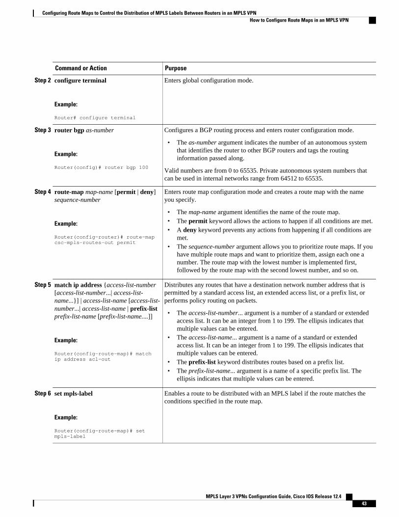
Command or Action Purpose
Step 2 configure terminal
Example:
Router# configure terminal
Enters global configuration mode.
Step 3 router bgp as-number
Example:
Router(config)# router bgp 100
Configures a BGP routing process and enters router configuration mode.
• The as-number argument indicates the number of an autonomous systemthat identifies the router to other BGP routers and tags the routinginformation passed along.
Valid numbers are from 0 to 65535. Private autonomous system numbers thatcan be used in internal networks range from 64512 to 65535.
Step 4 route-map map-name [permit | deny]sequence-number
Example:
Router(config-router)# route-map csc-mpls-routes-out permit
Enters route map configuration mode and creates a route map with the nameyou specify.
• The map-name argument identifies the name of the route map.• The permit keyword allows the actions to happen if all conditions are met.• A deny keyword prevents any actions from happening if all conditions are
met.• The sequence-number argument allows you to prioritize route maps. If you
have multiple route maps and want to prioritize them, assign each one anumber. The route map with the lowest number is implemented first,followed by the route map with the second lowest number, and so on.
Step 5 match ip address {access-list-number[access-list-number...| access-list-name...}] | access-list-name [access-list-number...| access-list-name | prefix-listprefix-list-name [prefix-list-name....]]
Example:
Router(config-route-map)# match ip address acl-out
Distributes any routes that have a destination network number address that ispermitted by a standard access list, an extended access list, or a prefix list, orperforms policy routing on packets.
• The access-list-number... argument is a number of a standard or extendedaccess list. It can be an integer from 1 to 199. The ellipsis indicates thatmultiple values can be entered.
• The access-list-name... argument is a name of a standard or extendedaccess list. It can be an integer from 1 to 199. The ellipsis indicates thatmultiple values can be entered.
• The prefix-list keyword distributes routes based on a prefix list.• The prefix-list-name... argument is a name of a specific prefix list. The
ellipsis indicates that multiple values can be entered.
Step 6 set mpls-label
Example:
Router(config-route-map)# set mpls-label
Enables a route to be distributed with an MPLS label if the route matches theconditions specified in the route map.
Configuring Route Maps to Control the Distribution of MPLS Labels Between Routers in an MPLS VPNHow to Configure Route Maps in an MPLS VPN
MPLS Layer 3 VPNs Configuration Guide, Cisco IOS Release 12.4 43

Command or Action Purpose
Step 7 exit
Example:
Router(config-route-map)# exit
Exits route map configuration mode and returns to global configuration mode.
Applying the Route Maps to the MPLS VPN Edge RoutersThis configuration is optional.
Perform this task to enable the edge routers to use the route maps.
SUMMARY STEPS
1. enable
2. configure terminal
3. router bgp as-number
4. address-family ipv4 [multicast | unicast | vrf vrf-name]
5. neighbor ip-address route-map map-name in
6. neighbor ip-address route-map map-name out
7. neighbor ip-address send-label
8. exit-address-family
9. end
DETAILED STEPS
Command or Action Purpose
Step 1 enable
Example:
Router> enable
Enables privileged EXEC mode.
• Enter your password if prompted.
Step 2 configure terminal
Example:
Router# configure terminal
Enters global configuration mode.
Applying the Route Maps to the MPLS VPN Edge Routers How to Configure Route Maps in an MPLS VPN
MPLS Layer 3 VPNs Configuration Guide, Cisco IOS Release 12.444

Command or Action Purpose
Step 3 router bgp as-number
Example:
Router(config)# router bgp 100
Configures a BGP routing process and enters router configuration mode.
• The as-number argument indicates the number of an autonomoussystem that identifies the router to other BGP routers and tags therouting information passed along. Valid numbers are from 0 to65535. Private autonomous system numbers that can be used ininternal networks range from 64512 to 65535.
Step 4 address-family ipv4 [multicast | unicast |vrf vrf-name]
Example:
Router(config-router)# address-family ipv4 vrf vpn1
Specifies the IPv4 address family type and enters address familyconfiguration mode.
• The multicast keyword specifies IPv4 multicast address prefixes.• The unicast keyword specifies IPv4 unicast address prefixes.• The vrf vrf-name keyword and argument specify the name of the
VRF to associate with subsequent IPv4 address family configurationmode commands.
Step 5 neighbor ip-address route-map map-name in
Example:
Router(config-router-af)# neighbor pp.0.0.1 route-map csc-mpls-routes-in in
Applies a route map to incoming routes.
• The ip-address argument specifies the router to which the route mapis to be applied.
• The map-name argument specifies the name of the route map.• The in keyword applies the route map to incoming routes.
Step 6 neighbor ip-address route-map map-nameout
Example:
Router(config-router-af)# neighbor pp.0.0.1 route-map csc-mpls-route-out out
Applies a route map to outgoing routes.
• The ip-address argument specifies the router to which the route mapis to be applied.
• The map-name argument specifies the name of the route map.• The out keyword applies the route map to outgoing routes.
Step 7 neighbor ip-address send-label
Example:
Router(config-router-af)# neighbor pp.0.0.1 send-label
Enables a BGP router to send MPLS labels with BGP routes to aneighboring BGP router.
• The ip-address argument specifies the IP address of the neighboringrouter.
Step 8 exit-address-family
Example:
Router(config-router-af)# exit-address-family
Exits from address family configuration mode.
Configuring Route Maps to Control the Distribution of MPLS Labels Between Routers in an MPLS VPNHow to Configure Route Maps in an MPLS VPN
MPLS Layer 3 VPNs Configuration Guide, Cisco IOS Release 12.4 45

Command or Action Purpose
Step 9 end
Example:
Router(config-router)# end
(Optional) Exits to privileged EXEC mode.
• Troubleshooting Tips, page 46
Troubleshooting TipsYou can enter a show route-map map-name command to verify that the route map is applied to the PErouters.
Note After you make any changes to a route map, you need to reset the BGP connection for the changes to takeeffect.
Configuration Examples for Route Maps in MPLS VPNs• Using a Route Map in an MPLS VPN Inter-AS Network Example, page 46• Using a Route Map in an MPLS VPN CSC Network Example, page 47
Using a Route Map in an MPLS VPN Inter-AS Network ExampleIn this example, a route map is applied to an autonomous system border router (ASBR) that exchangesIPv4 routes and MPLS labels with another ASBR.
• A route map called OUT specifies that the ASBR should distribute the PE1 route (ee.ee) with labelsand the RR1 route (aa.aa) without labels.
• A route map called IN specifies that the ASBR should accept the PE2 route (ff.ff) with labels and theRR2 route (bb.bb) without labels.
ip subnet-zerompls label protocol tdp!interface Loopback0 ip address ww.ww.ww.ww 255.255.255.255 no ip directed-broadcast no ip route-cache no ip mroute-cache!interface Ethernet0/2 ip address hh.0.0.2 255.0.0.0 no ip directed-broadcast no ip mroute-cache!interface Ethernet0/3 ip address dd.0.0.1 255.0.0.0 no ip directed-broadcast
Using a Route Map in an MPLS VPN Inter-AS Network Example Troubleshooting Tips
MPLS Layer 3 VPNs Configuration Guide, Cisco IOS Release 12.446

no ip mroute-cache mpls label protocol ldp tag-switching ip!router ospf 10 log-adjacency-changes auto-cost reference-bandwidth 1000 redistribute connected subnets passive-interface Ethernet0/2 network ww.ww.ww.ww 0.0.0.0 area 100 network dd.0.0.0 0.255.255.255 area 100 router bgp 100 bgp log-neighbor-changes timers bgp 10 30 neighbor aa.aa.aa.aa remote-as 100 neighbor aa.aa.aa.aa update-source Loopback0 neighbor hh.0.0.1 remote-as 200 no auto-summary !!address-family ipv4 ! Redistributing IGP into BGP redistribute ospf 10 ! so that PE1 & RR1 loopbacks neighbor aa.aa.aa.aa activate ! get into the BGP table neighbor aa.aa.aa.aa send-label neighbor hh.0.0.1 activate neighbor hh.0.0.1 advertisement-interval 5 neighbor hh.0.0.1 send-label neighbor hh.0.0.1 route-map IN in ! accepting routes in route map IN. neighbor hh.0.0.1 route-map OUT out ! distributing routes in route map OUT. neighbor kk.0.0.1 activate neighbor kk.0.0.1 advertisement-interval 5 neighbor kk.0.0.1 send-label neighbor kk.0.0.1 route-map IN in ! accepting routes in route map IN. neighbor kk.0.0.1 route-map OUT out ! distributing routes in route map OUT. no auto-summary no synchronization exit-address-family!ip default-gateway 3.3.0.1ip classless!access-list 1 permit ee.ee.ee.ee log !Setting up the access listsaccess-list 2 permit ff.ff.ff.ff logaccess-list 3 permit aa.aa.aa.aa logaccess-list 4 permit bb.bb.bb.bb logroute-map IN permit 10 !Setting up the route maps match ip address 2 match mpls-label!route-map IN permit 11 match ip address 4!route-map OUT permit 12 match ip address 3!route-map OUT permit 13 match ip address 1 set mpls-label!end
Using a Route Map in an MPLS VPN CSC Network ExampleThe following example creates two route maps, which are named:
• IN for incoming routes• OUT for outgoing routes
The route maps specify the following:
Using a Route Map in an MPLS VPN CSC Network ExampleConfiguration Examples for Route Maps in MPLS VPNs
MPLS Layer 3 VPNs Configuration Guide, Cisco IOS Release 12.4 47

• If an IP address in an incoming BGP update message matches an IP address in access list 99, the routeis added to the BGP table.
• If an IP address in an outbound BGP update message matches an IP address in access list 88, the routerdistributes that route.
The route maps are applied to the CSC-PE router with the address qq.0.0.1.
address-family ipv4 vrf vpn2 neighbor qq.0.0.1 remote-as 200 neighbor qq.0.0.1 activate neighbor qq.0.0.1 as-override neighbor qq.0.0.1 advertisement-interval 5 neighbor qq.0.0.1 route-map IN in neighbor qq.0.0.1 route-map OUT out neighbor qq.0.0.1 send-label!access-list 88 permit rr.rr.rr.rraccess-list 88 permit ss.ss.ss.ssaccess-list 88 permit tt.tt.tt.ttaccess-list 99 permit uu.uu.uu.uuaccess-list 99 permit vv.vv.vv.vvaccess-list 99 permit ww.ww.ww.ww!route-map IN permit 1 match ip address 99!route-map OUT permit 1 match ip address 88 set mpls-label!
Additional ReferencesRelated Documents
Related Topic Document Title
Basic MPLS VPNs Configuring MPLS Layer 3 VPNs
MPLS VPN Carrier Supporting Carrier • MPLS VPN Carrier Supporting Carrier UsingLDP and an IGP
• MPLS VPN Carrier Supporting Carrier withBGP
MPLS VPN InterAutonomous Systems • MPLS VPN Inter-AS with ASBRs ExchangingIPv4 Routes and MPLS Labels
• MPLS VPN Inter-AS with ASBRs ExchangingVPN-IPv4 Addresses
Configuring Route Maps to Control the Distribution of MPLS Labels Between Routers in an MPLS VPN Additional References
MPLS Layer 3 VPNs Configuration Guide, Cisco IOS Release 12.448

Standards
Standard Title
No new or modified standards are supported by thisfeature, and support for existing standards has notbeen modified by this feature.
--
MIBs
MIB MIBs Link
No new or modified MIBs are supported by thisfeature, and support for existing MIBs has not beenmodified by this feature.
To locate and download MIBs for selectedplatforms, Cisco software releases, and feature sets,use Cisco MIB Locator found at the followingURL:
http://www.cisco.com/go/mibs
RFCs
RFC Title
RFC 2547 BGP/MPLS VPNs
Configuring Route Maps to Control the Distribution of MPLS Labels Between Routers in an MPLS VPNAdditional References
MPLS Layer 3 VPNs Configuration Guide, Cisco IOS Release 12.4 49

Technical Assistance
Description Link
The Cisco Technical Support website containsthousands of pages of searchable technical content,including links to products, technologies, solutions,technical tips, and tools. Registered Cisco.comusers can log in from this page to access even morecontent.
The Cisco Technical Support website containsthousands of pages of searchable technical content,including links to products, technologies, solutions,technical tips, and tools. Registered Cisco.comusers can log in from this page to access even morecontent.
The Cisco Support website provides extensiveonline resources, including documentation and toolsfor troubleshooting and resolving technical issueswith Cisco products and technologies.
To receive security and technical information aboutyour products, you can subscribe to variousservices, such as the Product Alert Tool (accessedfrom Field Notices), the Cisco Technical ServicesNewsletter, and Really Simple Syndication (RSS)Feeds.
Access to most tools on the Cisco Support websiterequires a Cisco.com user ID and password.
http://www.cisco.com/techsupport
Feature Information for Route Maps in MPLS VPNsThe following table provides release information about the feature or features described in this module.This table lists only the software release that introduced support for a given feature in a given softwarerelease train. Unless noted otherwise, subsequent releases of that software release train also support thatfeature.
Use Cisco Feature Navigator to find information about platform support and Cisco software image support.To access Cisco Feature Navigator, go to www.cisco.com/go/cfn. An account on Cisco.com is not required.
Configuring Route Maps to Control the Distribution of MPLS Labels Between Routers in an MPLS VPN Feature Information for Route Maps in MPLS VPNs
MPLS Layer 3 VPNs Configuration Guide, Cisco IOS Release 12.450

Table 2 Feature Information for Route Maps in MPLS VPNs
Feature Name Releases Feature Configuration Information
This feature was included as partof the following features:
• MPLS VPN Inter-Autonomous Systems - IPv4BGP Label Distribution
• MPLS VPN CarrierSupporting Carrier with IPv4BGP Label Distribution
12.0(21)ST
12.0(22)S
12.0(23)S
12.2(13)T
12.0(24)S
12.2(14)S
12.0(27)S
12.0(29)S
Route maps enable you to specifywhich routes are distributed withMPLS labels. Route maps alsoenable you to specify whichroutes with MPLS labels a routerreceives and adds to its BGPtable.
Cisco and the Cisco logo are trademarks or registered trademarks of Cisco and/or its affiliates in the U.S.and other countries. To view a list of Cisco trademarks, go to this URL: www.cisco.com/go/trademarks.Third-party trademarks mentioned are the property of their respective owners. The use of the word partnerdoes not imply a partnership relationship between Cisco and any other company. (1110R)
Any Internet Protocol (IP) addresses and phone numbers used in this document are not intended to beactual addresses and phone numbers. Any examples, command display output, network topology diagrams,and other figures included in the document are shown for illustrative purposes only. Any use of actual IPaddresses or phone numbers in illustrative content is unintentional and coincidental.
Configuring Route Maps to Control the Distribution of MPLS Labels Between Routers in an MPLS VPN
MPLS Layer 3 VPNs Configuration Guide, Cisco IOS Release 12.4 51

Using a Route Map in an MPLS VPN CSC Network Example
MPLS Layer 3 VPNs Configuration Guide, Cisco IOS Release 12.452

Dialing to Destinations with the Same IPAddress for MPLS VPNs
The dialer software in Cisco IOS prior to Release 12.2(8)T had no way to dial two different destinationswith the same IP address. More specifically, in networks where a network access server (NAS) supportsdialing clients with overlapping addresses, dial-out attempts fail. This module explains how to dial tomore than one destination with the same IP address.
• Finding Feature Information, page 53• Prerequisites for Dialing to Destinations with the Same IP Address for MPLS VPNs, page 53• Restrictions for Dialing to Destinations with the Same IP Address for MPLS VPNs, page 54• Information About Dialing to Destinations with the Same IP Address for MPLS VPNs, page 55• How to Enable Dialing to Destinations with the Same IP Address for MPLS VPNs, page 56• Configuration Examples for Dialing to Destinations with the Same IP Address, page 59• Additional References, page 63• Feature Information for Dialing to Destinations with the Same IP Address, page 65
Finding Feature InformationYour software release may not support all the features documented in this module. For the latest featureinformation and caveats, see the release notes for your platform and software release. To find informationabout the features documented in this module, and to see a list of the releases in which each feature issupported, see the Feature Information Table at the end of this document.
Use Cisco Feature Navigator to find information about platform support and Cisco software image support.To access Cisco Feature Navigator, go to www.cisco.com/go/cfn. An account on Cisco.com is not required.
Prerequisites for Dialing to Destinations with the Same IPAddress for MPLS VPNs
Before configuring this feature, you should understand how to configure the following network features:
• Virtual profiles with two-way AAA authentication• MPLS VPNs
Refer to the documents listed in the Additional References, page 63 section for information aboutconfiguring these features.
MPLS Layer 3 VPNs Configuration Guide, Cisco IOS Release 12.4 53

Restrictions for Dialing to Destinations with the Same IPAddress for MPLS VPNs
When configuring static routes in an MPLS or MPLS VPN environment, some variations of the ip routeand ip route vrf commands are not supported. These variations of the commands are not supported inCisco IOS releases that support the Tag Forwarding Information Base (TFIB), specifically Cisco IOSReleases 12.xT, 12.xM, and 12.0S. The TFIB cannot resolve prefixes when the recursive route over whichthe prefixes travel disappears and then reappears. However, the command variations are supported in CiscoIOS releases that support the MPLS Forwarding Infrastructure (MFI), specifically Cisco IOS Release12.2(25)S and later. Use the following guidelines when configuring static routes.
Supported Static Routes in an MPLS Environment
The following ip route command is supported when you configure static routes in MPLS environment:
ip route destination-prefix mask interface next-hop-address
The following ip route commands are supported when you configure static routes in an MPLSenvironment and configure load sharing with static nonrecursive routes and a specific outbound interface:
ip route destination-prefix mask interface1 next-hop1
ip route destination-prefix mask interface2 next-hop2
Unsupported Static Routes in an MPLS Environment that Uses the TFIB
The following ip route command is not supported when you configure static routes in an MPLSenvironment:
ip route destination-prefix mask next-hop-address
The following ip route command is not supported when you configure static routes in an MPLSenvironment and enable load sharing where the next hop can be reached through two paths:
ip route destination-prefix mask next-hop-address
The following ip route command is not supported when you configure static routes in an MPLSenvironment and enable load sharing where the destination can be reached through two next hops:
ip route destination-prefix mask next-hop1
ip route destination-prefix mask next-hop2
Use the interface an next-hop arguments when specifying static routes.
Supported Static Routes in an MPLS VPN Environment
The following ip route vrf commands are supported when you configure static routes in a MPLS VPNenvironment, and the next hop and interface are in the same VRF:
• ◦ ip route vrf vrf-name destination-prefix mask next-hop-address◦ ip route vrf vrf-name destination-prefix mask interface next-hop-address◦ ip route vrf vrf-name destination-prefix mask interface1 next-hop1◦ ip route vrf vrf-name destination-prefix mask interface2 next-hop2
The following ip route vrf commands are supported when you configure static routes in a MPLS VPNenvironment, and the next hop is in the global table in the MPLS cloud in the global routing table. Forexample, these commands are supported when the next hop is pointing to the Internet Gateway.
Dialing to Destinations with the Same IP Address for MPLS VPNs Restrictions for Dialing to Destinations with the Same IP Address for MPLS VPNs
MPLS Layer 3 VPNs Configuration Guide, Cisco IOS Release 12.454

• ◦ ip route vrf vrf-name destination-prefix mask next-hop-address global◦ ip route vrf vrf-name destination-prefix mask interface next-hop-address (This command is
supported when the next hop and interface are in the core.)
The following ip route commands are supported when you configure static routes in a MPLS VPNenvironment and enable load sharing with static nonrecursive routes and a specific outbound interfaces:
ip route destination-prefix mask interface1 next-hop1
ip route destination-prefix mask interface2 next-hop2
Unsupported Static Routes in an MPLS VPN Environment that Uses the TFIB
The following ip route command is not supported when you configure static routes in a MPLS VPNenvironment, the next hop is in the global table in the MPLS cloud within the core, and you enable loadsharing where the next hop can be reached through two paths:
ip route vrf vrf-name destination-prefix mask next-hop-address global
The following ip route commands are not supported when you configure static routes in a MPLS VPNenvironment, the next hop is in the global table in the MPLS cloud within the core, and you enable loadsharing where the destination can be reached through two next hops:
ip route vrf destination-prefix mask next-hop1 global
ip route vrf destination-prefix mask next-hop2 global
The following ip route vrf commands are not supported when you configure static routes in an MPLSVPN environment, and the next hop and interface are in the same VRF:
ip route vrf vrf-name destination-prefix mask next-hop1
ip route vrf vrf-name destination-prefix mask next-hop2
Supported Static Routes in an MPLS VPN Environment Where the Next Hop Resides in the Global Table onthe CE Router
The following ip route vrf command is supported when you configure static routes in a MPLS VPNenvironment, and the next hop is in the global table on the CE side. For example, the following command issupported when the destination-prefix is the CE router’s loopback address, as in EBGP multihop cases.
ip route vrf vrf-name destination-prefix mask interface next-hop-address
The following ip route commands are supported when you configure static routes in a MPLS VPNenvironment, the next hop is in the global table on the CE side, and you enable load sharing with static non-recursive routes and a specific outbound interfaces:
ip route destination-prefix mask interface1 nexthop1
ip route destination-prefix mask interface2 nexthop2
Information About Dialing to Destinations with the Same IPAddress for MPLS VPNs
• Introduction to Dialing to Destinations with the Same IP Address for MPLS VPNs, page 56
• Benefits of this Feature, page 56
Dialing to Destinations with the Same IP Address for MPLS VPNsInformation About Dialing to Destinations with the Same IP Address for MPLS VPNs
MPLS Layer 3 VPNs Configuration Guide, Cisco IOS Release 12.4 55

Introduction to Dialing to Destinations with the Same IP Address for MPLSVPNs
The Cisco IOS dialer software can distinguish between two destinations with the same IP address usinginformation stored in the VRF. This capability is provided to the dialer software by two existing Cisco IOScommands, dialer map and ip route, which have been enhanced to include VPN routing and forwarding(VRF) information.
In previous Cisco IOS releases, the dialer software obtained the telephone number for dial-out based on thedestination IP address configured in the dialer map command. Now, the enhanced dialer map commandsupplies the name of the VRF so that the telephone number to be dialed is based on the VRF name and thedestination IP address. The VRF is identified based on the incoming interface of the packet, and is usedwith the destination IP address defined in the dialer map command to determine the telephone number tobe dialed.
The ip route configuration command also includes the VRF information. When a packet arrives in anincoming interface that belongs to a particular VRF, only those ip route commands that correspond to thatparticular VRF are used to determine the destination interface.
Benefits of this FeatureThis feature allows the dialer software to dial out in an MPLS-based VPN. The MPLS VPN modelsimplifies network routing. For example, rather than needing to manage routing over a complex virtualnetwork backbone composed of many virtual circuits, an MPLS VPN user can employ the backbone of theservice provider as the default route in communicating with all other VPN sites.
This default route capability allows several sites to transparently interconnect through the service providernetwork. One service provider network can support several different IP VPNs, each of which appears to itsusers as a separate, private network. Within a VPN, each site can send IP packets to any other site in thesame VPN, because each VPN is associated with one or more VRFs. The VRF is a key element in the VPNtechnology, because it maintains the routing information that defines a customer VPN site.
How to Enable Dialing to Destinations with the Same IPAddress for MPLS VPNs
• Mapping the VRF and Next-Hop Address to a Dial String, page 56
• Verifying the Configuration, page 58
Mapping the VRF and Next-Hop Address to a Dial StringUse the following procedure to map a VRF and next-hop address combination to a dial string and therebyallow the dialer software to be VRF-aware for an MPLS VPN.
These commands are only part of the required configuration and show how to map a VRF and next-hopaddress combination to a dial string. Refer to the documents listed in the Additional References, page 63section and the example in the Configuration Examples for Dialing to Destinations with the Same IPAddress, page 59 section for details on where to include these commands in the network configuration.
Introduction to Dialing to Destinations with the Same IP Address for MPLS VPNs How to Enable Dialing to Destinations with the Same IP Address for MPLS VPNs
MPLS Layer 3 VPNs Configuration Guide, Cisco IOS Release 12.456

SUMMARY STEPS
1. enable
2. configure terminal
3. interface dialer number
4. dialer map ip protocol-next-hop-address vrf vrf-name name host-name dial-string
5. end
6. ip route vrf vrf-name ip-address mask interface-type interface-number
DETAILED STEPS
Command or Action Purpose
Step 1 enable
Example:
Router> enable
Enables privileged EXEC mode.
• Enter your password if prompted.
Step 2 configure terminal
Example:
Router# configure terminal
Enters global configuration mode.
Step 3 interface dialer number
Example:
Router(config)# interface dialer 1
Enters interface configuration mode and beginsdialer configuration.
Step 4 dialer map ip protocol-next-hop-address vrf vrf-name name host-name dial-string
Example:
Router(config-if)# dialer map ip 60.0.0.12 vrf yellow name rubbertree02 5552171
Maps a VRF and next-hop address combination to adial string (telephone number).
Step 5 end
Example:
Router(config-if)# end
(Optional) Exits interface configuration mode.
Dialing to Destinations with the Same IP Address for MPLS VPNsHow to Enable Dialing to Destinations with the Same IP Address for MPLS VPNs
MPLS Layer 3 VPNs Configuration Guide, Cisco IOS Release 12.4 57

Command or Action Purpose
Step 6 ip route vrf vrf-name ip-address mask interface-type interface-number
Example:
Router(config)# ip route vrf blue 10.0.0.1 255.255.255.255 Dialer0
Configures a VRF and next hop addresscombination that points to the interface where thedialer software should make the connection.
Verifying the ConfigurationTo verify the configuration, use the following procedure.
SUMMARY STEPS
1. ping
2. show adjacency
DETAILED STEPS
Step 1 pingUse this command on the customer edge NAS to place a call to a peer. The expected result is that the NASsuccessfully dials out to that peer.
Step 2 show adjacencyUse this command if the call fails to check Cisco Express Forwarding (CEF) adjacency table information.
• Troubleshooting Tips, page 58
Troubleshooting TipsIf you encounter problems with the feature, use the following debug privileged EXEC commands on theNAS to help you determine where the problem lies:
• debug aaa authentication• debug aaa authorization• debug dialer• debug ppp authentication• debug ppp negotiation• debug radius
Verifying the Configuration Troubleshooting Tips
MPLS Layer 3 VPNs Configuration Guide, Cisco IOS Release 12.458

Configuration Examples for Dialing to Destinations with theSame IP Address
This section provides a configuration example of the feature for a simple network topology shown in thefigure below.
Figure 2 MPLS VPN Topology
Note The network addresses and telephone numbers used in the following configuration are examples only andwill not work in an actual network configuration.
Customer Edge (CE) Router
!hostname oaktree02enable secret 5 !1!35Fg$Ep4.D8JGpg7rKxQa49BF9/!ip subnet-zerono ip domain-lookup!controller T1 5/0!controller T1 5/1!interface FastEthernet0/0 no ip address no ip mroute-cache duplex auto speed auto!interface FastEthernet0/1 no ip address no ip mroute-cache shutdown duplex auto speed auto!interface Ethernet1/0 ip address 10.0.58.11 255.255.255.0 no ip mroute-cache half-duplex!interface Ethernet1/1 ip address 50.0.0.2 255.0.0.0 no ip mroute-cache half-duplex
Dialing to Destinations with the Same IP Address for MPLS VPNsConfiguration Examples for Dialing to Destinations with the Same IP Address
MPLS Layer 3 VPNs Configuration Guide, Cisco IOS Release 12.4 59

!interface Ethernet1/2 no ip address no ip mroute-cache shutdown half-duplex!interface Ethernet1/3 no ip address no ip mroute-cache shutdown half-duplex!interface Serial2/0 no ip address no ip mroute-cache shutdown no fair-queue serial restart-delay 0!interface Serial2/1 no ip address no ip mroute-cache shutdown serial restart-delay 0!interface Serial2/2 no ip address no ip mroute-cache shutdown serial restart-delay 0!interface Serial2/3 no ip address no ip mroute-cache shutdown serial restart-delay 0!interface FastEthernet4/0 no ip address no ip mroute-cache shutdown duplex auto speed auto!ip classlessip route 0.0.0.0 0.0.0.0 10.0.58.1ip route 60.0.0.0 255.0.0.0 50.0.0.1no ip http server!!snmp-server managerbanner motd ^C AV-8B OAKTREE^Calias exec r sh run!line con 0 exec-timeout 0 0line aux 0 loginline vty 0 4 no login!end
Provider Edge (PE) Router
hostname pinetree02!aaa new-model!!aaa authentication login con-log none
Dialing to Destinations with the Same IP Address for MPLS VPNs Configuration Examples for Dialing to Destinations with the Same IP Address
MPLS Layer 3 VPNs Configuration Guide, Cisco IOS Release 12.460

aaa authentication ppp default group radiusaaa authorization network default group radius aaa session-id commonenable secret 5 $1$7KlA$xpC8l4dJCZogbzZvGUtFl/!username rubbertree02 password 0 Helloip subnet-zero!no ip domain-lookup!ip vrf yellow rd 100:1ip cefvirtual-profile aaaisdn switch-type primary-5ess!controller T1 3/0 framing esf linecode b8zs pri-group timeslots 1-24!controller T1 3/1 framing esf linecode b8zs!controller T1 3/2 framing esf linecode b8zs!controller T1 3/3 framing esf linecode b8zs!controller T1 3/4 framing esf linecode b8zs!controller T1 3/5 framing esf linecode b8zs!controller T1 3/6 framing esf linecode b8zs!controller T1 3/7 framing esf linecode b8zs!interface Loopback0 ip vrf forwarding yellow ip address 70.0.0.1 255.0.0.0!interface FastEthernet1/0 no ip address shutdown duplex half!interface Ethernet2/0 ip address 10.0.58.3 255.255.255.0 duplex full!interface Ethernet2/1 ip vrf forwarding yellow ip address 50.0.0.1 255.0.0.0 duplex half!interface Ethernet2/2 no ip address shutdown duplex half!interface Ethernet2/3
Dialing to Destinations with the Same IP Address for MPLS VPNsConfiguration Examples for Dialing to Destinations with the Same IP Address
MPLS Layer 3 VPNs Configuration Guide, Cisco IOS Release 12.4 61

no ip address shutdown duplex half!interface Serial3/0:23 description phone# 555-3123 no ip address encapsulation ppp dialer rotary-group 0 dialer-group 1 isdn switch-type primary-5ess ppp authentication chap!interface Serial4/0 no ip address shutdown no fair-queue!interface Dialer0 ip address negotiated encapsulation ppp dialer in-band dialer map ip 60.0.0.12 vrf yellow name rubbertree02 5552171 dialer map ip 60.0.0.2 5552172 dialer-group 1 ppp authentication chap!ip classlessip route 0.0.0.0 0.0.0.0 10.0.58.1ip route 60.0.0.2 255.255.255.255 Dialer0ip route vrf yellow 60.0.0.0 255.0.0.0 Dialer0 permanentno ip http serverip pim bidir-enable!ip director cache time 60dialer-list 1 protocol ip permit!radius-server host 172.19.192.89 auth-port 1645 acct-port 1646 key rad123radius-server retransmit 3call rsvp-sync!no mgcp timer receive-rtcp!mgcp profile default!dial-peer cor custom!gatekeeper shutdown!banner motd ^C F/A-18 PINETREE ^C!line con 0 exec-timeout 0 0 login authentication con-log line aux 0line vty 5 15!end
Peer Router
hostname rubbertree02!logging buffered 32000 debuggingenable secret 5 $1$RCKC$scgtdlaDzjSyUVAi7KK5Q.enable password Windy!username pinetree02 password 0 Hello!ip subnet-zero
Dialing to Destinations with the Same IP Address for MPLS VPNs Configuration Examples for Dialing to Destinations with the Same IP Address
MPLS Layer 3 VPNs Configuration Guide, Cisco IOS Release 12.462

no ip domain-lookup!isdn switch-type basic-5ess!interface Ethernet0 ip address 10.0.58.9 255.255.255.0 no ip route-cache!interface BRI0 description phone# 555-2171 ip address 60.0.0.12 255.0.0.0 encapsulation ppp no ip route-cache dialer map ip 60.0.0.11 5553123 dialer map ip 60.0.0.2 5552172 dialer-group 1 isdn switch-type basic-5ess isdn fast-rollover-delay 45!ip default-gateway 10.0.58.1ip classlessip route 0.0.0.0 0.0.0.0 10.0.58.1ip route 50.0.0.0 255.0.0.0 70.0.0.1no ip http server!dialer-list 1 protocol ip permitno cdp runbanner motd ^C F-4B RUBBERTREE^C!line con 0 exec-timeout 0 0line vty 0 4 password Windy login!end
AAA Server User File
[aaa-serv]/usr/testing/bin> ./radiusd_1.16 -d . -a . -xgreentree-16 Password = "Hello", Expiration = "Dec 31 2005" Service-Type = Framed-User, Framed-Protocol = PPP cisco-avpair = "lcp:interface-config=ip vrf forwarding yellow \nip unnumbered Loopback0"
Additional ReferencesRelated Documents
Related Topic Document Title
MPLS MPLS Product Literature
Standards
Standard Title
No new or modified standards are supported by thisfeature, and support for existing standards has notbeen modified by this feature.
--
Dialing to Destinations with the Same IP Address for MPLS VPNsAdditional References
MPLS Layer 3 VPNs Configuration Guide, Cisco IOS Release 12.4 63

MIBs
MIB MIBs Link
No new or modified MIBs are supported by thisfeature, and support for existing MIBs has not beenmodified by this feature.
To locate and download MIBs for selectedplatforms, Cisco software releases, and feature sets,use Cisco MIB Locator found at the followingURL:
http://www.cisco.com/go/mibs
RFCs
RFC Title
RFC 1164 Application of the Border Gateway Protocol in theInternet
RFC 1171 A Border Gateway Protocol 4
RFC 1700 Assigned Numbers
RFC 1966 BGP Route Reflection: An Alternative to Full MeshIBGP
RFC 2283 Multiprotocol Extensions for BGP-4
RFC 2547 BGP/MPLS VPNs
RFC 2842 Capabilities Advertisement with BGP-4
RFC 2858 Multiprotocol Extensions for BGP-4
Dialing to Destinations with the Same IP Address for MPLS VPNs Additional References
MPLS Layer 3 VPNs Configuration Guide, Cisco IOS Release 12.464

Technical Assistance
Description Link
The Cisco Technical Support website containsthousands of pages of searchable technical content,including links to products, technologies, solutions,technical tips, and tools. Registered Cisco.comusers can log in from this page to access even morecontent.
The Cisco Support website provides extensiveonline resources, including documentation and toolsfor troubleshooting and resolving technical issueswith Cisco products and technologies.
To receive security and technical information aboutyour products, you can subscribe to variousservices, such as the Product Alert Tool (accessedfrom Field Notices), the Cisco Technical ServicesNewsletter, and Really Simple Syndication (RSS)Feeds.
Access to most tools on the Cisco Support websiterequires a Cisco.com user ID and password.
http://www.cisco.com/techsupport
Feature Information for Dialing to Destinations with the SameIP Address
The following table provides release information about the feature or features described in this module.This table lists only the software release that introduced support for a given feature in a given softwarerelease train. Unless noted otherwise, subsequent releases of that software release train also support thatfeature.
Use Cisco Feature Navigator to find information about platform support and Cisco software image support.To access Cisco Feature Navigator, go to www.cisco.com/go/cfn. An account on Cisco.com is not required.
Table 3 Feature Information for Dialing to Destinations with the Same IP Address
Feature Name Releases Feature Configuration Information
Dialer Map VRF-Aware forMPLS VPNs
12.2(8)T The Cisco IOS dialer software is"VRF-aware for an MPLS VPN,"which means that it candistinguish between twodestinations with the same IPaddress using information storedin the VRF.
Dialing to Destinations with the Same IP Address for MPLS VPNsFeature Information for Dialing to Destinations with the Same IP Address
MPLS Layer 3 VPNs Configuration Guide, Cisco IOS Release 12.4 65

Cisco and the Cisco logo are trademarks or registered trademarks of Cisco and/or its affiliates in the U.S.and other countries. To view a list of Cisco trademarks, go to this URL: www.cisco.com/go/trademarks.Third-party trademarks mentioned are the property of their respective owners. The use of the word partnerdoes not imply a partnership relationship between Cisco and any other company. (1110R)
Any Internet Protocol (IP) addresses and phone numbers used in this document are not intended to beactual addresses and phone numbers. Any examples, command display output, network topology diagrams,and other figures included in the document are shown for illustrative purposes only. Any use of actual IPaddresses or phone numbers in illustrative content is unintentional and coincidental.
Dialing to Destinations with the Same IP Address for MPLS VPNs
MPLS Layer 3 VPNs Configuration Guide, Cisco IOS Release 12.466

Ensuring MPLS VPN Clients Communicate overthe Backbone Links
This module describes how to configure a sham-link that ensures traffic travels between Virtual PrivateNetwork (VPN) client sites over the Multiprotocol Label Switching (MPLS) VPN backbone. This featureis for VPNs that run Open Shortest Path First (OSPF) between the provider edge (PE) and customer edge(CE) routers. By default, OSPF uses backdoor paths between VPN sites, not the MPLS VPN backbone.
• Finding Feature Information, page 67• Prerequisites for Ensuring MPLS VPN Clients Communicate over the Backbone Links, page 67• Restrictions for Ensuring MPLS VPN Clients Communicate over the Backbone Links, page 68• Information About Ensuring MPLS VPN Clients Communicate over the Backbone Links, page 68• How to Ensure That MPLS VPN Clients Communicate over the MPLS VPN Backbone, page 71• Configuration Examples for Ensuring MPLS VPN Clients Communicate over the MPLS VPN
Backbone, page 73• Additional References, page 76• Feature Information for Ensuring MPLS VPN Clients Communicate over the MPLS VPN Backbone,
page 77
Finding Feature InformationYour software release may not support all the features documented in this module. For the latest featureinformation and caveats, see the release notes for your platform and software release. To find informationabout the features documented in this module, and to see a list of the releases in which each feature issupported, see the Feature Information Table at the end of this document.
Use Cisco Feature Navigator to find information about platform support and Cisco software image support.To access Cisco Feature Navigator, go to www.cisco.com/go/cfn. An account on Cisco.com is not required.
Prerequisites for Ensuring MPLS VPN Clients Communicateover the Backbone Links
Before you can configure a sham-link in an MPLS VPN, you must first enable OSPF as follows:
• Create an OSPF routing process.• Specify the range of IP addresses to be associated with the routing process.• Assign area IDs to be associated with the range of IP addresses.
MPLS Layer 3 VPNs Configuration Guide, Cisco IOS Release 12.4 67

Restrictions for Ensuring MPLS VPN Clients Communicateover the Backbone Links
When OSPF is used as a protocol between PE and CE routers, the OSPF metric is preserved when routesare advertised over the VPN backbone. The metric is used on the remote PE routers to select the correctroute. For this reason, you should not modify the metric value when OSPF is redistributed to BorderGateway Protocol (BGP), and when BGP is redistributed to OSPF. If you modify the metric value, routingloops may occur.
Information About Ensuring MPLS VPN Clients Communicateover the Backbone Links
• Introduction to MPLS VPNs Using OSPF Between PE and CE Routers, page 68• OSPF Uses Backdoor Paths to Communicate Between VPN Sites, page 69• Sham-Links Direct Traffic Between VPN Sites over the MPLS VPN Backbone, page 70
Introduction to MPLS VPNs Using OSPF Between PE and CE RoutersIn an MPLS VPN configuration, the OSPF protocol is one way you can connect CE routers to PE routers inthe VPN backbone. OSPF is often used by customers that run OSPF as their intrasite routing protocol,subscribe to a VPN service, and want to exchange routing information between their sites using OSPF(during migration or on a permanent basis) over an MPLS VPN backbone.
The figure below shows an example of how VPN client sites (areas 0, 1, 2, and 3) that run OSPF canconnect over an MPLS VPN backbone.
When OSPF is used to connect PE and CE routers, all routing information learned from a VPN site isplaced in the VPN routing and forwarding (VRF) instance associated with the incoming interface. The PE
Introduction to MPLS VPNs Using OSPF Between PE and CE Routers Restrictions for Ensuring MPLS VPN Clients Communicate over the Backbone Links
MPLS Layer 3 VPNs Configuration Guide, Cisco IOS Release 12.468

routers that attach to the VPN use the BGP to distribute VPN routes to each other. A CE router can thenlearn the routes to other sites in the VPN by peering with its attached PE router. The MPLS VPN backboneprovides an additional level of routing hierarchy to interconnect the VPN sites running OSPF.
When OSPF routes are propagated over the MPLS VPN backbone, additional information about the prefixin the form of BGP extended communities (route type, domain ID extended communities) is appended tothe BGP update. This community information is used by the receiving PE router to decide the type of link-state advertisement (LSA) to be generated when the BGP route is redistributed to the OSPF PECE process.In this way, internal OSPF routes that belong to the same VPN and are advertised over the VPN backboneare seen as interarea routes on the remote sites.
OSPF Uses Backdoor Paths to Communicate Between VPN SitesAlthough OSPF PECE connections assume that the only path between two client sites is across the MPLSVPN backbone, backdoor paths between VPN sites may exist. For instance, in the figure below, Vienna,Stockholm, Brighton, and Winchester can communicate through backdoor paths instead of using the MPLSVPN backbone.
If the sites belong to the same OSPF area, the backdoor path will always be selected, because OSPF prefersintra-area paths to interarea paths. (PE routers advertise OSPF routes learned over the VPN backbone asinterarea paths.) For this reason, OSPF backdoor paths between VPN sites must be taken into account sothat routing is performed based on policy.
For example, the figure above shows three client sites, each with backdoor links. Because each site runsOSPF within the same Area 1 configuration, all routing between the three sites uses the backdoor paths,rather than the MPLS VPN backbone.
The following example shows BGP routing table entries for the Winchester router (prefix 10.3.1.7/32) fromthe standpoint of the PE1 router in the figure. Prefix 10.3.1.7 is the loopback interface of the Winchester
OSPF Uses Backdoor Paths to Communicate Between VPN SitesInformation About Ensuring MPLS VPN Clients Communicate over the Backbone Links
MPLS Layer 3 VPNs Configuration Guide, Cisco IOS Release 12.4 69

CE router. As shown in bold in this example, the loopback interface is learned via BGP from PE2 and PE3.It is also generated through redistribution into BGP on PE1.
PE1# show ip bgp vpnv4 all 10.3.1.7BGP routing table entry for 100:251:10.3.1.7/32, version 58Paths: (3 available, best #2) Advertised to non peer-group peers: 10.3.1.2 10.3.1.5 Local 10.3.1.5 (metric 30) from 10.3.1.5 (10.3.1.5) Origin incomplete, metric 22, localpref 100, valid, internal Extended Community: RT:1:793 OSPF DOMAIN ID:0.0.0.100 OSPF RT:1:2:0 OSPF 2 Local 10.2.1.38 from 0.0.0.0 (10.3.1.6) Origin incomplete, metric 86, localpref 100, weight 32768, valid, sourced, best Extended Community: RT:1:793 OSPF DOMAIN ID:0.0.0.100 OSPF RT:1:2:0 OSPF 2 Local 10.3.1.2 (metric 30) from 10.3.1.2 (10.3.1.2) Origin incomplete, metric 11, localpref 100, valid, internal Extended Community: RT:1:793 OSPF DOMAIN ID:0.0.0.100 OSPF RT:1:2:0 OSPF 2
Within BGP, the locally generated route (10.2.1.38) is considered to be the best route.
However, as shown in bold in the next example, the VRF routing table shows that the selected path islearned via OSPF with a next hop of 10.2.1.38, which is the Vienna CE router.
PE1# show ip route vrf ospf 10.3.1.7Routing entry for 10.3.1.7/32 Known via "ospf 100", distance 110, metric 86, type intra area Redistributing via bgp 215 Advertised by bgp 215 Last update from 10.2.1.38 on Serial0/0/0, 00:00:17 ago Routing Descriptor Blocks: * 10.2.1.38, from 10.3.1.7, 00:00:17 ago, via Serial0/0/0 Route metric is 86, traffic share count is 1
This path is selected because:
• The OSPF backdoor path is preferred over the interarea path (over the MPLS VPN backbone)generated by the PE1 router.
• OSPF has a lower administrative distance (AD) than internal BGP (BGP running between routers inthe same autonomous system).
If the backdoor paths between sites are used only for backup purposes and do not participate in the VPNservice, then the default route selection is acceptable. You can set up the OSPF cost configured with asham-link to send VPN site traffic over a backdoor path.
Sham-Links Direct Traffic Between VPN Sites over the MPLS VPNBackbone
To ensure that VPN sites that belong to the same OSPF area and share an OSPF backdoor pathcommunicate with each other using the MPLS VPN backbone, you must create a sham-link. (If nobackdoor path exists between the sites, no sham-link is required.) A sham-link is an additional OSPF intra-area (logical) link between ingress and egress VRFs on the PE routers that connect to the CE routers of theVPN sites.
The figure below shows a sample sham-link between PE1 and PE2. You associate a cost with each sham-link to force traffic to use the sham-link rather than the backdoor path. When a sham-link is configured
Sham-Links Direct Traffic Between VPN Sites over the MPLS VPN Backbone Information About Ensuring MPLS VPN Clients Communicate over the Backbone Links
MPLS Layer 3 VPNs Configuration Guide, Cisco IOS Release 12.470

between PE routers, the PE routers can populate the VRF routing table with the OSPF routes learned overthe sham-link.
Because the sham-link is seen as an intra-area link between PE routers, an OSPF adjacency is created anddatabase exchange (for the particular OSPF process) occurs across the link. The PE router can then floodLSAs between sites from across the MPLS VPN backbone. As a result, the desired intra-area connectivityis created.
How to Ensure That MPLS VPN Clients Communicate over theMPLS VPN Backbone
This section explains how to create a sham-link on an MPLS VPN PE router. Perform this task on both PErouters that share the sham-link.
Before you create a sham-link between PE routers in an MPLS VPN, you must:
• Configure a separate /32 address on the remote PE so that OSPF packets can be sent over the VPNbackbone to the remote end of the sham-link. The /32 address must meet the following criteria:
◦ Belong to a VRF.◦ Not be advertised by OSPF.◦ Be advertised by BGP.
You can use the /32 address for other sham-links.
• Associate the sham-link with an existing OSPF area.
Ensuring MPLS VPN Clients Communicate over the Backbone LinksHow to Ensure That MPLS VPN Clients Communicate over the MPLS VPN Backbone
MPLS Layer 3 VPNs Configuration Guide, Cisco IOS Release 12.4 71

SUMMARY STEPS
1. enable
2. configure terminal
3. interface loopback interface-number
4. ip vrf forwarding vrf-name
5. ip address ip-address mask
6. end
7. router ospf process-idvrf vrf-name
8. area area-id sham-link source-address destination-address cost number
9. show ip ospf sham-links
DETAILED STEPS
Command or Action Purpose
Step 1 enable
Example:
Router> enable
Enables privileged EXEC mode.
• Enter your password if prompted.
Step 2 configure terminal
Example:
Router# configure terminal
Enters global configuration mode.
Step 3 interface loopback interface-number
Example:
Router(config)# interface loopback 1
Creates a loopback interface to be used as an endpoint of thesham-link on the PE router and enters interface configurationmode.
Step 4 ip vrf forwarding vrf-name
Example:
Router(config-if)# ip vrf forwarding ospf
Associates the loopback interface with a VRF. Removes the IPaddress.
Step 5 ip address ip-address mask
Example:
Router(config-if)# ip address 10.2.1.2 255.255.255.255
Reconfigures the IP address of the loopback interface on the PErouter.
Ensuring MPLS VPN Clients Communicate over the Backbone Links How to Ensure That MPLS VPN Clients Communicate over the MPLS VPN Backbone
MPLS Layer 3 VPNs Configuration Guide, Cisco IOS Release 12.472

Command or Action Purpose
Step 6 end
Example:
Router(config-if)# end
Returns to global configuration mode.
Step 7 router ospf process-idvrf vrf-name
Example:
Router(config)# router ospf 100 vrf ospf
Configures the specified OSPF process with the VRF associatedwith the sham-link interface on the PE router and entersinterface configuration mode.
Step 8 area area-id sham-link source-address destination-address cost number
Example:
Router(config-if)# area 1 sham-link 10.2.1.2 10.2.1.1 cost 40
Configures the sham-link on the PE router interface within aspecified OSPF area and with the loopback interfaces specifiedby the IP addresses as endpoints.
• cost number configures the OSPF cost for sending an IPpacket over the PE sham-link interface.
Step 9 show ip ospf sham-links
Example:
Verifies that the sham-link was successfully created and isoperational.
Example
The following is sample output from the show ip ospf sham-links command:
Router# show ip ospf sham-linksSham Link OSPF_SL0 to address 10.2.1.2 is upArea 1 source address 10.2.1.1 Run as demand circuit DoNotAge LSA allowed. Cost of using 40 State POINT_TO_POINT, Timer intervals configured, Hello 10, Dead 40, Wait 40, Hello due in 00:00:04 Adjacency State FULL (Hello suppressed) Index 2/2, retransmission queue length 4, number of retransmission 0 First 0x63311F3C(205)/0x63311FE4(59) Next 0x63311F3C(205)/0x63311FE4(59) Last retransmission scan length is 0, maximum is 0 Last retransmission scan time is 0 msec, maximum is 0 msec Link State retransmission due in 360 msec
Configuration Examples for Ensuring MPLS VPN ClientsCommunicate over the MPLS VPN Backbone
Ensuring MPLS VPN Clients Communicate over the Backbone LinksConfiguration Examples for Ensuring MPLS VPN Clients Communicate over the MPLS VPN Backbone
MPLS Layer 3 VPNs Configuration Guide, Cisco IOS Release 12.4 73

The following example shows how to configure a sham-link between two PE routers:
Router1(config)# interface loopback 1Router1(config-if)# ip vrf forwarding ospfRouter1(config-if)# ip address 10.2.1.1 255.255.255.255!Router2(config)# interface loopback 1Router2(config-if)# ip vrf forwarding ospfRouter2(config-if)# ip address 10.2.1.2 255.255.255.255!Router1(config)# router ospf 100 vrf ospfRouter1(config-if)# area 1 sham-link 10.2.1.1 10.2.1.2 cost 40!Router2(config)# router ospf 100 vrf ospfRouter2(config-if)# area 1 sham-link 10.2.1.2 10.2.1.1 cost 40
This example shows how a sham-link is used only to affect the OSPF intra-area path selection of the PEand CE routers. The PE router also uses the information received from Multiprotocol BGP (MP-BGP) toset the outgoing label stack of incoming packets, and to decide to which egress PE router to label-switchthe packets.
The figure below shows a sample MPLS VPN topology in which a sham-link configuration is necessary. AVPN client has three sites, each with a backdoor path. Two sham-links have been configured, one betweenPE1 and PE2, and another between PE2 and PE3. A sham-link between PE1 and PE3 is not necessary inthis configuration, because the Vienna and Winchester sites do not share a backdoor path.
The following example shows the forwarding that occurs between sites from the standpoint of how PE1views the 10.3.1.7/32 prefix, the loopback1 interface of the Winchester CE router in the figure above.
PE1# show ip bgp vpnv4 all 10.3.1.7BGP routing table entry for 100:251:10.3.1.7/32, version 124Paths: (1 available, best #1) Local 10.3.1.2 (metric 30) from 10.3.1.2 (10.3.1.2) Origin incomplete, metric 11, localpref 100, valid, internal,
Ensuring MPLS VPN Clients Communicate over the Backbone Links Configuration Examples for Ensuring MPLS VPN Clients Communicate over the MPLS VPN Backbone
MPLS Layer 3 VPNs Configuration Guide, Cisco IOS Release 12.474
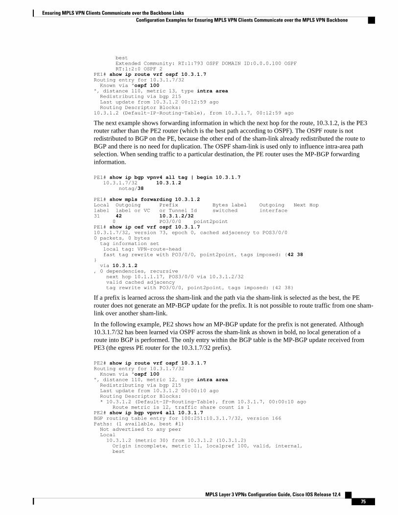
best Extended Community: RT:1:793 OSPF DOMAIN ID:0.0.0.100 OSPF RT:1:2:0 OSPF 2PE1# show ip route vrf ospf 10.3.1.7Routing entry for 10.3.1.7/32 Known via "ospf 100", distance 110, metric 13, type intra area Redistributing via bgp 215 Last update from 10.3.1.2 00:12:59 ago Routing Descriptor Blocks:10.3.1.2 (Default-IP-Routing-Table), from 10.3.1.7, 00:12:59 ago
The next example shows forwarding information in which the next hop for the route, 10.3.1.2, is the PE3router rather than the PE2 router (which is the best path according to OSPF). The OSPF route is notredistributed to BGP on the PE, because the other end of the sham-link already redistributed the route toBGP and there is no need for duplication. The OSPF sham-link is used only to influence intra-area pathselection. When sending traffic to a particular destination, the PE router uses the MP-BGP forwardinginformation.
PE1# show ip bgp vpnv4 all tag | begin 10.3.1.7 10.3.1.7/32 10.3.1.2 notag/38
PE1# show mpls forwarding 10.3.1.2Local Outgoing Prefix Bytes label Outgoing Next Hoplabel label or VC or Tunnel Id switched interface 31 42 10.3.1.2/32 0 PO3/0/0 point2point PE1# show ip cef vrf ospf 10.3.1.710.3.1.7/32, version 73, epoch 0, cached adjacency to POS3/0/00 packets, 0 bytes tag information set local tag: VPN-route-head fast tag rewrite with PO3/0/0, point2point, tags imposed: {42 38} via 10.3.1.2, 0 dependencies, recursive next hop 10.1.1.17, POS3/0/0 via 10.3.1.2/32 valid cached adjacency tag rewrite with PO3/0/0, point2point, tags imposed: {42 38}
If a prefix is learned across the sham-link and the path via the sham-link is selected as the best, the PErouter does not generate an MP-BGP update for the prefix. It is not possible to route traffic from one sham-link over another sham-link.
In the following example, PE2 shows how an MP-BGP update for the prefix is not generated. Although10.3.1.7/32 has been learned via OSPF across the sham-link as shown in bold, no local generation of aroute into BGP is performed. The only entry within the BGP table is the MP-BGP update received fromPE3 (the egress PE router for the 10.3.1.7/32 prefix).
PE2# show ip route vrf ospf 10.3.1.7Routing entry for 10.3.1.7/32 Known via "ospf 100", distance 110, metric 12, type intra area Redistributing via bgp 215 Last update from 10.3.1.2 00:00:10 ago Routing Descriptor Blocks: * 10.3.1.2 (Default-IP-Routing-Table), from 10.3.1.7, 00:00:10 ago Route metric is 12, traffic share count is 1PE2# show ip bgp vpnv4 all 10.3.1.7BGP routing table entry for 100:251:10.3.1.7/32, version 166Paths: (1 available, best #1) Not advertised to any peer Local 10.3.1.2 (metric 30) from 10.3.1.2 (10.3.1.2) Origin incomplete, metric 11, localpref 100, valid, internal, best
Ensuring MPLS VPN Clients Communicate over the Backbone LinksConfiguration Examples for Ensuring MPLS VPN Clients Communicate over the MPLS VPN Backbone
MPLS Layer 3 VPNs Configuration Guide, Cisco IOS Release 12.4 75

Extended Community: RT:1:793 OSPF DOMAIN ID:0.0.0.100 OSPF RT:1:2:0 OSPF 2
The PE router uses the information received from MP-BGP to set the ongoing label stack of incomingpackets, and to decide to which egress PE router to label-switch the packets.
Additional ReferencesRelated Documents
Related Topic Document Title
Basic MPLS VPNs Configuring MPLS Layer 3 VPNs
MPLS VPN Carrier Supporting Carrier • MPLS VPN Carrier Supporting Carrier UsingLDP and an IGP
• MPLS VPN Carrier Supporting Carrier withBGP
MPLS VPN InterAutonomous Systems • MPLS VPN Inter-AS with ASBRs ExchangingIPv4 Routes and MPLS Labels
• MPLS VPN Inter-AS with ASBRs ExchangingVPN-IPv4 Addresses
Standards
Standard Title
No new or modified standards are supported by thisfeature, and support for existing standards has notbeen modified by this feature.
--
MIBs
MIB MIBs Link
No new or modified MIBs are supported by thisfeature, and support for existing MIBs has not beenmodified by this feature.
To locate and download MIBs for selectedplatforms, Cisco software releases, and feature sets,use Cisco MIB Locator found at the followingURL:
http://www.cisco.com/go/mibs
RFCs
RFC Title
RFC 1164 Application of the Border Gateway Protocol in theInternet
Ensuring MPLS VPN Clients Communicate over the Backbone Links Additional References
MPLS Layer 3 VPNs Configuration Guide, Cisco IOS Release 12.476

RFC Title
RFC 1171 A Border Gateway Protocol 4
RFC 1700 Assigned Numbers
RFC 1966 BGP Route Reflection: An Alternative to Full MeshIBGP
RFC 2283 Multiprotocol Extensions for BGP-4
RFC 2328 Open Shortest Path First, Version 2
RFC 2547 BGP/MPLS VPNs
RFC 2842 Capabilities Advertisement with BGP-4
RFC 2858 Multiprotocol Extensions for BGP-4
RFC 3107 Carrying Label Information in BGP-4
Technical Assistance
Description Link
The Cisco Technical Support website containsthousands of pages of searchable technical content,including links to products, technologies, solutions,technical tips, and tools. Registered Cisco.comusers can log in from this page to access even morecontent.
The Cisco Support website provides extensiveonline resources, including documentation and toolsfor troubleshooting and resolving technical issueswith Cisco products and technologies.
To receive security and technical information aboutyour products, you can subscribe to variousservices, such as the Product Alert Tool (accessedfrom Field Notices), the Cisco Technical ServicesNewsletter, and Really Simple Syndication (RSS)Feeds.
Access to most tools on the Cisco Support websiterequires a Cisco.com user ID and password.
http://www.cisco.com/techsupport
Feature Information for Ensuring MPLS VPN ClientsCommunicate over the MPLS VPN Backbone
The following table provides release information about the feature or features described in this module.This table lists only the software release that introduced support for a given feature in a given software
Ensuring MPLS VPN Clients Communicate over the Backbone LinksFeature Information for Ensuring MPLS VPN Clients Communicate over the MPLS VPN Backbone
MPLS Layer 3 VPNs Configuration Guide, Cisco IOS Release 12.4 77

release train. Unless noted otherwise, subsequent releases of that software release train also support thatfeature.
Use Cisco Feature Navigator to find information about platform support and Cisco software image support.To access Cisco Feature Navigator, go to www.cisco.com/go/cfn. An account on Cisco.com is not required.
Table 4 Feature Information for Ensuring MPLS VPN Clients Communicate over the MPLS VPN Backbone
Feature Name Releases Feature Configuration Information
Ensuring MPLS VPN ClientsCommunicate over the MPLSVPN Backbone
12.2(8)T
12.0(21)ST
12.0(22)S
This feature allows you toconfigure a sham-link that directstraffic between Virtual PrivateNetwork (VPN) client sites overthe Multiprotocol LabelSwitching (MPLS) VPNbackbone.
Cisco and the Cisco logo are trademarks or registered trademarks of Cisco and/or its affiliates in the U.S.and other countries. To view a list of Cisco trademarks, go to this URL: www.cisco.com/go/trademarks.Third-party trademarks mentioned are the property of their respective owners. The use of the word partnerdoes not imply a partnership relationship between Cisco and any other company. (1110R)
Any Internet Protocol (IP) addresses and phone numbers used in this document are not intended to beactual addresses and phone numbers. Any examples, command display output, network topology diagrams,and other figures included in the document are shown for illustrative purposes only. Any use of actual IPaddresses or phone numbers in illustrative content is unintentional and coincidental.
Ensuring MPLS VPN Clients Communicate over the Backbone Links
MPLS Layer 3 VPNs Configuration Guide, Cisco IOS Release 12.478

Configuring Scalable Hub-and-Spoke MPLSVPNs
This module explains how to ensure that virtual private network (VPN) clients that connect to the sameprovider edge (PE) router at the edge of the Mutliprotocol (MPLS) Virtual Private Network (VPN) use thehub site. This feature prevents the VPN clients from communicating directly with each other, bypassingthe hub site. This feature also provides scalable hub-and-spoke connectivity for subscribers of an MPLSVPN service by removing the requirement of one VRF per spoke.
• Finding Feature Information, page 79• Prerequisites for Configuring Scalable Hub-and-Spoke MPLS VPNs, page 79• Restrictions for Configuring Scalable Hub-and-Spoke MPLS VPNs, page 80• Information about Configuring Scalable Hub-and-Spoke MPLS VPNs, page 80• How to Ensure that MPLS VPN Clients Use the Hub PE Router, page 81• Configuration Examples for Configuring Scalable Hub-and-Spoke MPLS VPNs, page 87• Additional References, page 90• Feature Information for Configuring Scalable Hub-and-Spoke MPLS VPNs, page 91
Finding Feature InformationYour software release may not support all the features documented in this module. For the latest featureinformation and caveats, see the release notes for your platform and software release. To find informationabout the features documented in this module, and to see a list of the releases in which each feature issupported, see the Feature Information Table at the end of this document.
Use Cisco Feature Navigator to find information about platform support and Cisco software image support.To access Cisco Feature Navigator, go to www.cisco.com/go/cfn. An account on Cisco.com is not required.
Prerequisites for Configuring Scalable Hub-and-Spoke MPLSVPNs
You must have a working MPLS core network.
MPLS Layer 3 VPNs Configuration Guide, Cisco IOS Release 12.4 79

Restrictions for Configuring Scalable Hub-and-Spoke MPLSVPNs
• In both the upstream and downstream VRFs, routing protocols are not supported on interfacesconfigured with this feature. Interfaces that are not configured with this feature, however, do not havethis restriction for the upstream or downstream VRFs.
• You can configure this feature only on virtual access interfaces (VAIs) and virtual template interfaces(VTIs).
• Only unnumbered interfaces are supported.• Multicast is not supported on interfaces configured for hub-and-spoke MPLS VPNs.
Information about Configuring Scalable Hub-and-SpokeMPLS VPNs
• Overview, page 80• Upstream and Downstream VRFs, page 81• Reverse Path Forwarding Check, page 81
OverviewThis feature prevents local connectivity between subscribers at the spoke provider edge (PE) router andensures that a hub site provides subscriber connectivity. Any sites that connect to the same PE router mustforward intersite traffic using the hub site. This ensures that the routing done at the spoke site moves fromthe access-side interface to the network-side interface or from the network-side interface to the access-sideinterface, but never from the access-side interface to the access-side interface.
This feature prevents situations where the PE router locally switches the spokes without passing the trafficthrough the hub site. This prevents subscribers from directly connecting to each other.
This feature eases configuration by removing the requirement of one VRF per spoke. In prior releases,when spokes connected to the same PE router, each spoke was configured in a separate VRF to ensure thatthe traffic between the spokes traversed the central link between the wholesale service provider and theISP. However, this solution was not scalable. When many spokes connected to the same PE router,configuration of VRFs for each spoke became quite complex and greatly increased memory usage. Thiswas especially true in large-scale environments that supported high-density remote access to Layer 3 VPNs.
The figure below shows a sample hub-and-spoke topology.
Figure 3 Hub-and-Spoke Topology
Overview Restrictions for Configuring Scalable Hub-and-Spoke MPLS VPNs
MPLS Layer 3 VPNs Configuration Guide, Cisco IOS Release 12.480

Upstream and Downstream VRFsThis feature uses two unidirectional VRFs to forward IP traffic between the spokes and the hub PE router:
• The upstream VRF forwards the IP traffic from the spokes toward the hub PE router. This VRFtypically contains only a default route but might also contain summary routes and multiple defaultroutes. The default route points to the interface on the hub PE router that connects to the upstream ISP.The router dynamically learns about the default route from the routing updates that the hub PE routeror home gateway sends. The upstream VRF also contains the VAIs that connect the spokes, but itcontains no other local interfaces.
• The downstream VRF forwards traffic from the hub PE router back to the spokes. This VRF containsPoint-to-Point Protocol (PPP) peer routes for the spokes and per-user static routes received from theAuthentication, Authorization, and Accounting (AAA) server. It also contains the routes importedfrom the hub PE router.
The router redistributes routes from the downstream VRF into Multiprotocol Border Gateway Protocol(MP-BGP). The spoke PE router typically advertises a summary route across the MPLS core for theconnected spokes. The VRF configured on the hub PE router imports the advertised summary route.
Reverse Path Forwarding CheckThe unicast Reverse Path Forwarding (RPF) check ensures that an IP packet that enters a router uses thecorrect inbound interface. This feature supports unicast RPF check on the spoke-side interfaces. Becausedifferent VRFs are used for downstream and upstream forwarding, the RPF mechanism ensures that sourceaddress checks occur in the downstream VRF.
How to Ensure that MPLS VPN Clients Use the Hub PE Router• Configuring the Upstream and Downstream VRFs on the PE Router or the Spoke PE Router, page81
• Associating VRFs, page 83
• Configuring the Downstream VRF for an AAA Server, page 84
• Verifying the Configuration, page 84
Configuring the Upstream and Downstream VRFs on the PE Router or theSpoke PE Router
To configure the upstream and downstream VRFs on the PE router or on the spoke PE router, use thefollowing procedure.
Upstream and Downstream VRFsHow to Ensure that MPLS VPN Clients Use the Hub PE Router
MPLS Layer 3 VPNs Configuration Guide, Cisco IOS Release 12.4 81

SUMMARY STEPS
1. enable
2. configure terminal
3. ip vrf vrf-name
4. rd route-distinguisher
5. route-target {import | export | both} route-target-ext-community
6. exit
DETAILED STEPS
Command or Action Purpose
Step 1 enable
Example:
Router> enable
Enables privileged EXEC mode.
• Enter your password if prompted.
Step 2 configure terminal
Example:
Router# configure terminal
Enters global configuration mode.
Step 3 ip vrf vrf-name
Example:
Router(config)# ip vrf U
Enters VRF configuration mode and defines the VRF instance byassigning a VRF name.
Step 4 rd route-distinguisher
Example:
Router(config-vrf)# rd 1:0
Creates routing and forwarding tables.
Step 5 route-target {import | export | both} route-target-ext-community
Example:
Router(config-vrf)# route-target import 1:0
Creates a list of import and export route target communities for thespecified VRF.
• The import keyword is required to create an upstream VRF.The upstream VRF is used to import the default route from thehub PE router.
• The export keyword is required to create a downstream VRF.The downstream VRF is used to export the routes of allsubscribers of a given service that the VRF serves.
Configuring Scalable Hub-and-Spoke MPLS VPNs How to Ensure that MPLS VPN Clients Use the Hub PE Router
MPLS Layer 3 VPNs Configuration Guide, Cisco IOS Release 12.482
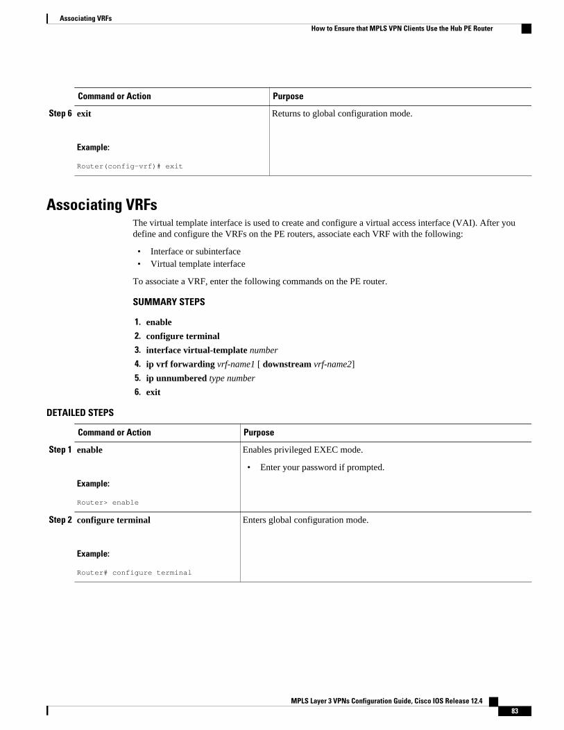
Command or Action Purpose
Step 6 exit
Example:
Router(config-vrf)# exit
Returns to global configuration mode.
Associating VRFsThe virtual template interface is used to create and configure a virtual access interface (VAI). After youdefine and configure the VRFs on the PE routers, associate each VRF with the following:
• Interface or subinterface• Virtual template interface
To associate a VRF, enter the following commands on the PE router.
SUMMARY STEPS
1. enable
2. configure terminal
3. interface virtual-template number
4. ip vrf forwarding vrf-name1 [ downstream vrf-name2]
5. ip unnumbered type number
6. exit
DETAILED STEPS
Command or Action Purpose
Step 1 enable
Example:
Router> enable
Enables privileged EXEC mode.
• Enter your password if prompted.
Step 2 configure terminal
Example:
Router# configure terminal
Enters global configuration mode.
Associating VRFsHow to Ensure that MPLS VPN Clients Use the Hub PE Router
MPLS Layer 3 VPNs Configuration Guide, Cisco IOS Release 12.4 83

Command or Action Purpose
Step 3 interface virtual-template number
Example:
Router(config)# interface virtual-template 1
Creates a virtual template interface that can be configured and applieddynamically in creating virtual access interfaces. Enters interfaceconfiguration mode.
Step 4 ip vrf forwarding vrf-name1[ downstream vrf-name2]
Example:
Router(config-if)# ip vrf forwarding vpn1 downstream D
Associates a virtual template interface with the VRF you specify.
• The vrf-name1 argument is the name of the VRF associated with thevirtual template interface.
• The vrf-name2 argument is the name of the downstream VRF into whichthe PPP peer route and all of the per-user routes from the AAA serverare installed. If an AAA server is used, it provides the VRFmembership; you do not need to configure the VRF members on thevirtual templates.
Step 5 ip unnumbered type number
Example:
Router(config-if)# ip unnumbered Loopback1
Enables IP processing on an interface without assigning an explicit IPaddress to the interface.
The type and number arguments are the type and number of another interfaceon which the router has an assigned IP address. It cannot be anotherunnumbered interface.
Step 6 exit
Example:
Router(config-if)# exit
Returns to global configuration mode.
Configuring the Downstream VRF for an AAA ServerTo configure the downstream VRF for an AAA server, enter the following Cisco attribute value:
lcp:interface-config=ip vrf forwarding U downstream D
For more information about configuring a RADIUS server, see Configuring Virtual Template Interfaces.
Verifying the ConfigurationTo verify the configuration, perform the following steps.
SUMMARY STEPS
1. show ip vrf [brief | detail | interfaces | id] [vrf-name]
2. show ip route vrf vrf-name
3. show running-config [ interface type number]
Configuring the Downstream VRF for an AAA Server How to Ensure that MPLS VPN Clients Use the Hub PE Router
MPLS Layer 3 VPNs Configuration Guide, Cisco IOS Release 12.484

DETAILED STEPS
Step 1 show ip vrf [brief | detail | interfaces | id] [vrf-name]Use this command to display information about all of the VRFs configured on the router, including the downstreamVRF for each associated VAI.
Example:
Router# show ip vrf Name Default RD Interface D 2:0 Loopback2 Virtual-Access3 [D] Virtual-Access4 [D] U 2:1 Virtual-Access3 Virtual-Access4
show ip vrf detail vrf-name
Use this command to display detailed information about the VRF you specify, including all of the VAIs associatedwith the VRF.
If you do not specify a value for vrf-name, detailed information about all of the VRFs configured on the routerappears, including all of the VAIs associated with each VRF.
The following example shows how to display detailed information for the VRF called vrf1.
Example:
Router# show ip vrf detail vrf1 VRF D; default RD 2:0; default VPNID <not set> Interfaces: Loopback2 Virtual-Access3 [D] Virtual-Access4 [D] Connected addresses are not in global routing table Export VPN route-target communities RT:2:0 Import VPN route-target communities RT:2:1 No import route-map No export route-mapVRF U; default RD 2:1; default VPNID <not set> Interfaces: Virtual-Access3 Virtual-Access4 Connected addresses are not in global routing table No Export VPN route-target communities Import VPN route-target communities RT:2:1 No import route-map No export route-map
Step 2 show ip route vrf vrf-nameUse this command to display the IP routing table for the VRF you specify, and information about the per-user staticroutes installed in the downstream VRF.
The following example shows how to display the routing table for the downstream VRF named D.
Configuring Scalable Hub-and-Spoke MPLS VPNsHow to Ensure that MPLS VPN Clients Use the Hub PE Router
MPLS Layer 3 VPNs Configuration Guide, Cisco IOS Release 12.4 85

Example:
Router# show ip route vrf D Routing Table: DCodes: C - connected, S - static, R - RIP, M - mobile, B - BGP D - EIGRP, EX - EIGRP external, O - OSPF, IA - OSPF inter area N1 - OSPF NSSA external type 1, N2 - OSPF NSSA external type 2 E1 - OSPF external type 1, E2 - OSPF external type 2 i - IS-IS, L1 - IS-IS level-1, L2 - IS-IS level-2, ia - IS-IS interarea * - candidate default, U - per-user static route, o - ODR P - periodic downloaded static routeGateway of last resort is not set 2.0.0.0/8 is variably subnetted, 5 subnets, 2 masksU 2.0.0.2/32 [1/0] via 2.8.1.1S 2.0.0.0/8 is directly connected, Null0U 2.0.0.5/32 [1/0] via 2.8.1.2C 2.8.1.2/32 is directly connected, Virtual-Access4C 2.8.1.1/32 is directly connected, Virtual-Access3
The following example shows how to display the routing table for the upstream VRF named U.
Example:
Router# show ip route vrf U Routing Table: UCodes: C - connected, S - static, R - RIP, M - mobile, B - BGP D - EIGRP, EX - EIGRP external, O - OSPF, IA - OSPF inter area N1 - OSPF NSSA external type 1, N2 - OSPF NSSA external type 2 E1 - OSPF external type 1, E2 - OSPF external type 2 i - IS-IS, L1 - IS-IS level-1, L2 - IS-IS level-2, ia - IS-IS interarea * - candidate default, U - per-user static route, o - ODR P - periodic downloaded static routeGateway of last resort is 100.0.0.20 to network 0.0.0.0 2.0.0.0/32 is subnetted, 1 subnetsC 2.0.0.8 is directly connected, Loopback2B* 0.0.0.0/0 [200/0] via 100.0.0.20, 1w5d
Step 3 show running-config [ interface type number]Use this command to display information about the virtual access interface you specify, including information aboutthe upstream and downstream VRFs.
The following example shows how to display information about the interface named virtual-access 3.
Example:
Router# show running-config interface virtual-access 3Building configuration...Current configuration : 92 bytes!interface Virtual-Access3 ip vrf forwarding U downstream D ip unnumbered Loopback2end
The following example shows how to display information about the interface named virtual-access 4.
Example:
Router# show running-config interface virtual-access 4Building configuration...Current configuration : 92 bytes!
Configuring Scalable Hub-and-Spoke MPLS VPNs How to Ensure that MPLS VPN Clients Use the Hub PE Router
MPLS Layer 3 VPNs Configuration Guide, Cisco IOS Release 12.486

interface Virtual-Access4 ip vrf forwarding U downstream D ip unnumbered Loopback2end
Configuration Examples for Configuring Scalable Hub-and-Spoke MPLS VPNs
• Configuring the Upstream and Downstream VRFs on the PE Router and the Spoke PE RouterExample, page 87
• Associating VRFs Example, page 87
• Configuring Scalable Hub-and-Spoke MPLS VPNs--Basic Configuration Example, page 88
• Example, page 89
Configuring the Upstream and Downstream VRFs on the PE Router and theSpoke PE Router Example
The following example configures an upstream VRF named U:
Router> enable Router# configure terminalRouter(config)# ip vrf URouter(config-vrf)# rd 1:0Router(config-vrf)# route-target import 1:0
The following example configures a downstream VRF named D:
Router> enableRouter# configure terminalRouter(config)# ip vrf D Router(config-vrf)# rd 1:8 Router(config-vrf)# route-target export 1:100
Associating VRFs ExampleThe following example associates the VRF named U with the virtual-template 1 interface and specifies thedownstream VRF named D:
Router> enable Router# configure terminalRouter(config)# interface virtual-template 1Router(config-if)# ip vrf forwarding U downstream DRouter(config-if)# ip unnumbered Loopback1
Configuring the Upstream and Downstream VRFs on the PE Router and the Spoke PE Router ExampleConfiguration Examples for Configuring Scalable Hub-and-Spoke MPLS VPNs
MPLS Layer 3 VPNs Configuration Guide, Cisco IOS Release 12.4 87

Configuring Scalable Hub-and-Spoke MPLS VPNs--Basic ConfigurationExample
In this example, local authentication is used; that is, the RADIUS server is not used.
This example uses the hub-and-spoke topology shown in the figure below.
Figure 4 Sample Topology
ip vrf D rd 1:8 route-target export 1:100 ! ip vrf U rd 1:0 route-target import 1:0 ! ip cef vpdn enable ! vpdn-group U accept-dialin protocol pppoe virtual-template 1 ! interface Loopback2 ip vrf forwarding U ip address 2.0.0.8 255.255.255.255 ! interface ATM2/0 description Mze ATM3/1/2 no ip address no atm ilmi-keepalive pvc 0/16 ilmi ! pvc 3/100 protocol pppoe !pvc 3/101 protocol pppoe!interface Virtual-Template1 ip vrf forwarding U downstream D ip unnumbered Loopback2 peer default ip address pool U-pool ppp authentication chap
Configuring Scalable Hub-and-Spoke MPLS VPNs--Basic Configuration Example Configuration Examples for Configuring Scalable Hub-and-Spoke MPLS VPNs
MPLS Layer 3 VPNs Configuration Guide, Cisco IOS Release 12.488

ExampleThe following example shows how to connect two Point-to-Point Protocol over Ethernet (PPPoE) clients toa single VRF pair on the spoke PE router named Lipno. Although both PPPoE clients are configured in thesame VRF, all communication occurs using the hub PE router. Half-duplex VRFs are configured on thespoke PE. The client configuration is downloaded to the spoke PE from the RADIUS server.
This example uses the hub-and-spoke topology shown in the figure above.
Note The wholesale provider can forward the user authentication request to the corresponding ISP. If the ISPauthenticates the user, the wholesale provider appends the VRF information to the request that goes back tothe PE router.
aaa new-model!aaa group server radius R server 22.0.20.26 auth-port 1812 acct-port 1813!aaa authentication ppp default group radiusaaa authorization network default group radius!ip vrf D description Downstream VRF - to spokes rd 1:8 route-target export 1:100!ip vrf U description Upstream VRF - to hub rd 1:0 route-target import 1:0!ip cef vpdn enable! vpdn-group U accept-dialin protocol pppoe virtual-template 1!interface Loopback2 ip vrf forwarding U ip address 2.0.0.8 255.255.255.255!interface ATM2/0 pvc 3/100 protocol pppoe ! pvc 3/101 protocol pppoe !interface virtual-template 1 no ip address ppp authentication chap!router bgp 1 no synchronization neighbor 100.0.0.34 remote-as 1 neighbor 100.0.0.34 update-source Loopback0 no auto-summary !address-family vpnv4 neighbor 100.0.0.34 activate neighbor 100.0.0.34 send-community extended auto-summary exit-address-family
ExampleConfiguration Examples for Configuring Scalable Hub-and-Spoke MPLS VPNs
MPLS Layer 3 VPNs Configuration Guide, Cisco IOS Release 12.4 89

!address-family ipv4 vrf U no auto-summary no synchronization exit-address-family! address-family ipv4 vrf D redistribute static no auto-summary no synchronization exit-address-family !ip local pool U-pool 2.8.1.1 2.8.1.100ip route vrf D 2.0.0.0 255.0.0.0 Null0!radius-server host 22.0.20.26 auth-port 1812 acct-port 1813radius-server key cisco
Additional ReferencesRelated Documents
Related Topic Document Title
Basic MPLS VPNs Configuring MPLS Layer 3 VPNs
MPLS VPN Carrier Supporting Carrier • MPLS VPN Carrier Supporting Carrier UsingLDP and an IGP
• MPLS VPN Carrier Supporting Carrier withBGP
MPLS VPN InterAutonomous Systems • MPLS VPN Inter-AS with ASBRs ExchangingIPv4 Routes and MPLS Labels
• MPLS VPN Inter-AS with ASBRs ExchangingVPN-IPv4 Addresses
Standards
Standard Title
No new or modified standards are supported by thisfeature, and support for existing standards has notbeen modified by this feature.
—
MIBs
MIB MIBs Link
No new or modified MIBs are supported by thisfeature, and support for existing MIBs has not beenmodified by this feature.
To locate and download MIBs for selectedplatforms, Cisco IOS releases, and feature sets, useCisco MIB Locator found at the following URL:
http://www.cisco.com/go/mibs
Configuring Scalable Hub-and-Spoke MPLS VPNs Additional References
MPLS Layer 3 VPNs Configuration Guide, Cisco IOS Release 12.490
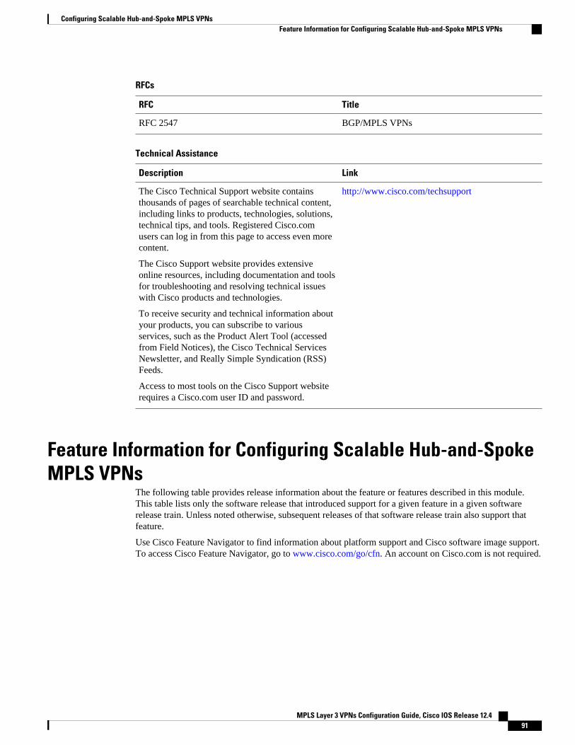
RFCs
RFC Title
RFC 2547 BGP/MPLS VPNs
Technical Assistance
Description Link
The Cisco Technical Support website containsthousands of pages of searchable technical content,including links to products, technologies, solutions,technical tips, and tools. Registered Cisco.comusers can log in from this page to access even morecontent.
The Cisco Support website provides extensiveonline resources, including documentation and toolsfor troubleshooting and resolving technical issueswith Cisco products and technologies.
To receive security and technical information aboutyour products, you can subscribe to variousservices, such as the Product Alert Tool (accessedfrom Field Notices), the Cisco Technical ServicesNewsletter, and Really Simple Syndication (RSS)Feeds.
Access to most tools on the Cisco Support websiterequires a Cisco.com user ID and password.
http://www.cisco.com/techsupport
Feature Information for Configuring Scalable Hub-and-SpokeMPLS VPNs
The following table provides release information about the feature or features described in this module.This table lists only the software release that introduced support for a given feature in a given softwarerelease train. Unless noted otherwise, subsequent releases of that software release train also support thatfeature.
Use Cisco Feature Navigator to find information about platform support and Cisco software image support.To access Cisco Feature Navigator, go to www.cisco.com/go/cfn. An account on Cisco.com is not required.
Configuring Scalable Hub-and-Spoke MPLS VPNsFeature Information for Configuring Scalable Hub-and-Spoke MPLS VPNs
MPLS Layer 3 VPNs Configuration Guide, Cisco IOS Release 12.4 91

Table 5 Feature Information for Configuring Scalable Hub-and-Spoke MPLS VPNs
Feature Name Releases Feature Configuration Information
MPLS VPN: Half Duplex VRFSupport
12.3(6)
12.3(11)T
This feature ensures that VPNclients that connect to the samePE router at the edge of theMPLS VPN use the hub site tocommunicate.
Cisco and the Cisco logo are trademarks or registered trademarks of Cisco and/or its affiliates in the U.S.and other countries. To view a list of Cisco trademarks, go to this URL: www.cisco.com/go/trademarks.Third-party trademarks mentioned are the property of their respective owners. The use of the word partnerdoes not imply a partnership relationship between Cisco and any other company. (1110R)
Any Internet Protocol (IP) addresses and phone numbers used in this document are not intended to beactual addresses and phone numbers. Any examples, command display output, network topology diagrams,and other figures included in the document are shown for illustrative purposes only. Any use of actual IPaddresses or phone numbers in illustrative content is unintentional and coincidental.
Configuring Scalable Hub-and-Spoke MPLS VPNs
MPLS Layer 3 VPNs Configuration Guide, Cisco IOS Release 12.492

Assigning an ID Number to a VPN
You can identify Virtual Private Networks (VPNs) by a VPN identification number, as described in RFC2685. This implementation of the VPN ID feature is used for identifying a VPN.
• Finding Feature Information, page 93• Information About VPN ID, page 93• How to Configure a VPN ID, page 95• Additional References, page 97• Feature Information for Assigning an ID Number to a VPN, page 99
Finding Feature InformationYour software release may not support all the features documented in this module. For the latest featureinformation and caveats, see the release notes for your platform and software release. To find informationabout the features documented in this module, and to see a list of the releases in which each feature issupported, see the Feature Information Table at the end of this document.
Use Cisco Feature Navigator to find information about platform support and Cisco software image support.To access Cisco Feature Navigator, go to www.cisco.com/go/cfn. An account on Cisco.com is not required.
Information About VPN ID• Introduction to VPN ID, page 93
• Components of the VPN ID, page 94
• Management Applications That Use VPN IDs, page 94
Introduction to VPN IDYou can identify VPNs by a VPN identification number, as described in RFC 2685. This implementation ofthe VPN ID feature is used for identifying a VPN. The VPN ID feature is not used to control thedistribution of routing information or to associate IP addresses with VPN ID numbers in the MP-BGPVPNv4 routing updates.
Multiple VPNs can be configured in a router. A VPN is private and uses a private address space that mightalso be used by another VPN or by the Internet. The IP address used in a VPN is only significant to theVPN in which it exists. You can use a VPN name (a unique ASCII string) to reference a specific VPNconfigured in the router. Alternately, you can use a VPN ID to identify a particular VPN in the router. The
MPLS Layer 3 VPNs Configuration Guide, Cisco IOS Release 12.4 93

VPN ID follows a standard specification (RFC 2685). To ensure that the VPN has a consistent VPN ID,assign the same VPN ID to all the routers in the service provider network that services that VPN.
Note Configuration of a VPN ID for a VPN is optional. You can still use a VPN name to identify configuredVPNs in the router. The VPN name is not affected by the VPN ID configuration. These are twoindependent mechanisms to identify VPNs.
Components of the VPN IDEach VPN ID defined by RFC 2685 consists of the following elements:
• An Organizational Unique Identifier (OUI), a three-octet hex number: The IEEE RegistrationAuthority assigns OUIs to any company that manufactures components under the ISO/IEC 8802standard. The OUI is used to generate universal LAN MAC addresses and protocol identifiers for usein local and metropolitan area network applications. For example, an OUI for Cisco Systems is00-03-6B (hex).
• A VPN index: a four-octet hex number, which identifies the VPN within the company.
Use the following vpn id command and specify the VPN ID:
vpn id oui:vpn-index
A colon separates the OUI from the VPN index.
Management Applications That Use VPN IDsYou can use several applications to manage VPNs by VPN ID. Remote access applications, such as theRemote Authentication Dial-In User Service (RADIUS) and Dynamic Host Configuration Protocol(DHCP), can use the VPN ID feature to identify a VPN. RADIUS can use the VPN ID to assign dial-inusers to the proper VPN, based on each user’s authentication information.
• Dynamic Host Configuration Protocol, page 94
• Remote Authentication Dial-In User Service, page 94
Dynamic Host Configuration ProtocolUsing DHCP network administrators can centrally manage and automate the assignment of IP addresses inan organization’s network. The DHCP application uses the VPN ID as follows:
1 A VPN DHCP client requests a connection to a provider edge (PE) router from a VRF interface.2 The PE router determines the VPN ID associated with that interface.3 The PE router sends a request with the VPN ID and other information for assigning an IP address to the
DHCP server.4 The DHCP server uses the VPN ID and IP address information to process the request.5 The DHCP server sends a response back to the PE router, allowing the VPN DHCP client access to the
VPN.
Remote Authentication Dial-In User Service
Components of the VPN ID Dynamic Host Configuration Protocol
MPLS Layer 3 VPNs Configuration Guide, Cisco IOS Release 12.494

A RADIUS server (or daemon) provides authentication and accounting services to one or more clientnetwork access servers (NASs). RADIUS servers authenticate users and return all configurationinformation necessary for the client to deliver service to the users.
Typically, a user login consists of a query (Access-Request) from the NAS to the RADIUS server and acorresponding response (Access-Accept or Access-Reject) from the server.
• The Access-Request packet contains the username, encrypted password, NAS IP address, VPN ID,and port. The format of the request also provides information on the type of session that the user wantsto initiate.
• The RADIUS server returns an Access-Accept response if it finds the username and verifies thepassword. The response includes a list of attribute-value pairs that describe the parameters to be usedfor this session. If the user is not authenticated, an Access-Reject is sent by the RADIUS server andaccess is denied.
How to Configure a VPN ID• Specifying a VPN ID, page 95
• Verifying the VPN ID Configuration, page 96
Specifying a VPN IDUse this procedure to specify a VPN ID.
• Restrictions, page 95
RestrictionsThe VPN ID feature is not used to control the distribution of routing information or to associate IPaddresses with VPN ID numbers in the MP-BGP VPNv4 routing updates.
Each VRF configured on a PE router can have a VPN ID configured. Configure all the PE routers thatbelong to the same VPN with the same VPN ID. Make sure the VPN ID is unique to the service providernetwork.
SUMMARY STEPS
1. enable
2. configure terminal
3. ip vrf vrf-name
4. vpn id oui:vpn-index :
Specifying a VPN IDHow to Configure a VPN ID
MPLS Layer 3 VPNs Configuration Guide, Cisco IOS Release 12.4 95
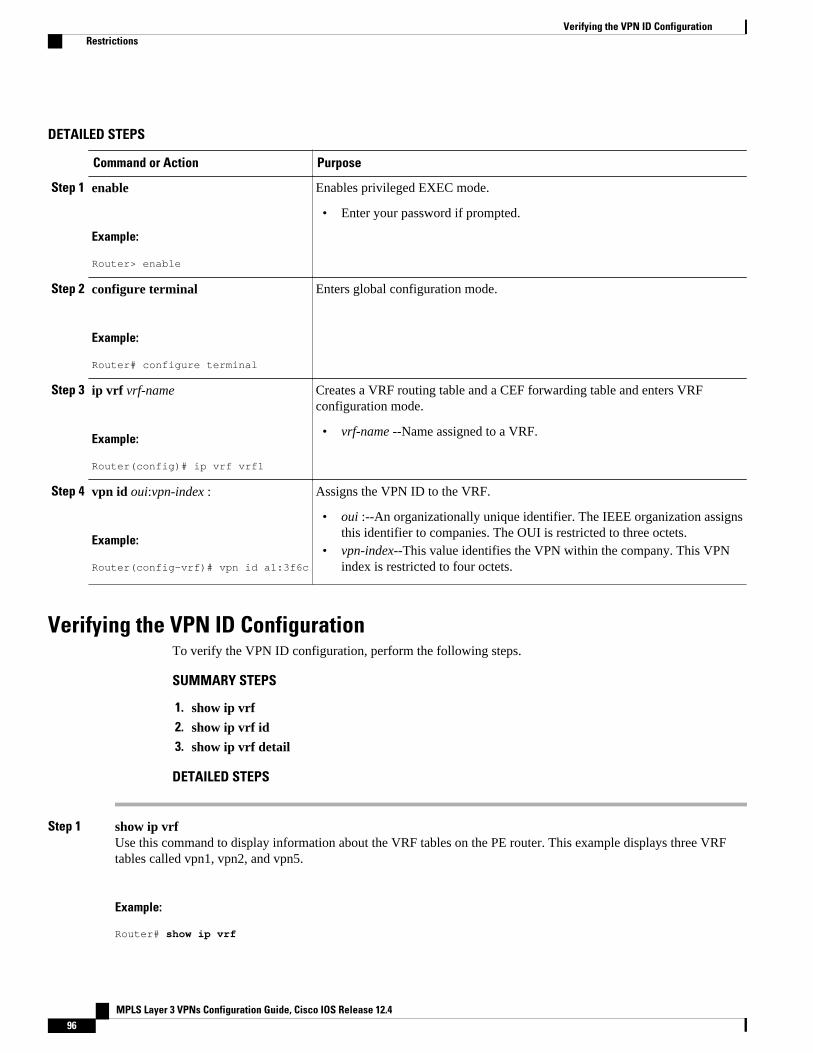
DETAILED STEPS
Command or Action Purpose
Step 1 enable
Example:
Router> enable
Enables privileged EXEC mode.
• Enter your password if prompted.
Step 2 configure terminal
Example:
Router# configure terminal
Enters global configuration mode.
Step 3 ip vrf vrf-name
Example:
Router(config)# ip vrf vrf1
Creates a VRF routing table and a CEF forwarding table and enters VRFconfiguration mode.
• vrf-name --Name assigned to a VRF.
Step 4 vpn id oui:vpn-index :
Example:
Router(config-vrf)# vpn id a1:3f6c
Assigns the VPN ID to the VRF.
• oui :--An organizationally unique identifier. The IEEE organization assignsthis identifier to companies. The OUI is restricted to three octets.
• vpn-index--This value identifies the VPN within the company. This VPNindex is restricted to four octets.
Verifying the VPN ID ConfigurationTo verify the VPN ID configuration, perform the following steps.
SUMMARY STEPS
1. show ip vrf
2. show ip vrf id
3. show ip vrf detail
DETAILED STEPS
Step 1 show ip vrfUse this command to display information about the VRF tables on the PE router. This example displays three VRFtables called vpn1, vpn2, and vpn5.
Example:
Router# show ip vrf
Verifying the VPN ID Configuration Restrictions
MPLS Layer 3 VPNs Configuration Guide, Cisco IOS Release 12.496

Name Default RD Interfaces vpn1 100:1 Ethernet1/1 Ethernet1/4 vpn2 <not set> vpn5 500:1 Loopback2
Step 2 show ip vrf idUse this command to ensure that the PE router contains the VPN ID you specified. The following example shows thatonly VRF tables vpn1 and vpn2 have VPN IDs assigned. The VRF table called vpn5 is not displayed, because it doesnot have a VPN ID.
Example:
Router# show ip vrf idVPN Id Name RD2:3 vpn2 <not set>A1:3F6C vpn1 100:1
Step 3 show ip vrf detailUse this command to see all the VRFs on a PE router. This command displays all the VPN IDs that are configured onthe router, their associated VRF names, and VRF route distinguishers (RDs). If a VRF table in the PE router has notbeen assigned a VPN ID, that VRF entry is not included in the output.
Example:
Router# show ip vrf detailVRF vpn1; default RD 100:1; default VPNID A1:3F6C Interfaces: Ethernet1/1 Ethernet1/4 Connected addresses are not in global routing table Export VPN route-target communities RT:100:1 Import VPN route-target communities RT:100:1 RT:500:1 No import route-map No export route-mapVRF vpn2; default RD <not set>; default VPNID 2:3 No interfaces Connected addresses are not in global routing table No Export VPN route-target communities No Import VPN route-target communities No import route-map No export route-mapVRF vpn5; default RD 500:1; default VPNID <not set> Interfaces:
Additional ReferencesRelated Documents
Related Topic Document Title
Basic MPLS VPNs Configuring MPLS Layer 3 VPNs
Assigning an ID Number to a VPNAdditional References
MPLS Layer 3 VPNs Configuration Guide, Cisco IOS Release 12.4 97

Related Topic Document Title
MPLS VPN Carrier Supporting Carrier • MPLS VPN Carrier Supporting Carrier UsingLDP and an IGP
• MPLS VPN Carrier Supporting Carrier withBGP
MPLS VPN InterAutonomous Systems • MPLS VPN Inter-AS with ASBRs ExchangingIPv4 Routes and MPLS Labels
• MPLS VPN Inter-AS with ASBRs ExchangingVPN-IPv4 Addresses
Standards
Standard Title
IEEE Std 802-1990 IEEE Local and Metropolitan Area Networks:Overview and Architecture
MIBs
MIB MIBs Link
None To locate and download MIBs for selectedplatforms, Cisco software releases, and feature sets,use Cisco MIB Locator found at the followingURL:
http://www.cisco.com/go/mibs
RFCs
RFC Title
RFC 2685 Virtual Private Networks Identifier
Assigning an ID Number to a VPN Additional References
MPLS Layer 3 VPNs Configuration Guide, Cisco IOS Release 12.498

Technical Assistance
Description Link
The Cisco Technical Support website containsthousands of pages of searchable technical content,including links to products, technologies, solutions,technical tips, and tools. Registered Cisco.comusers can log in from this page to access even morecontent.
The Cisco Support website provides extensiveonline resources, including documentation and toolsfor troubleshooting and resolving technical issueswith Cisco products and technologies.
To receive security and technical information aboutyour products, you can subscribe to variousservices, such as the Product Alert Tool (accessedfrom Field Notices), the Cisco Technical ServicesNewsletter, and Really Simple Syndication (RSS)Feeds.
Access to most tools on the Cisco Support websiterequires a Cisco.com user ID and password.
http://www.cisco.com/techsupport
Feature Information for Assigning an ID Number to a VPNThe following table provides release information about the feature or features described in this module.This table lists only the software release that introduced support for a given feature in a given softwarerelease train. Unless noted otherwise, subsequent releases of that software release train also support thatfeature.
Use Cisco Feature Navigator to find information about platform support and Cisco software image support.To access Cisco Feature Navigator, go to www.cisco.com/go/cfn. An account on Cisco.com is not required.
Table 6 Feature Information for Assigning an ID Number to a VPN
Feature Name Releases Feature Configuration Information
VPN ID 12.0(17)ST
12.2(4)B
12.2(8)T
12.2(14)S
This feature lets you you identifyVPNs by a VPN identificationnumber, as described in RFC2685.
Cisco and the Cisco logo are trademarks or registered trademarks of Cisco and/or its affiliates in the U.S.and other countries. To view a list of Cisco trademarks, go to this URL: www.cisco.com/go/trademarks.
Assigning an ID Number to a VPNFeature Information for Assigning an ID Number to a VPN
MPLS Layer 3 VPNs Configuration Guide, Cisco IOS Release 12.4 99

Third-party trademarks mentioned are the property of their respective owners. The use of the word partnerdoes not imply a partnership relationship between Cisco and any other company. (1110R)
Any Internet Protocol (IP) addresses and phone numbers used in this document are not intended to beactual addresses and phone numbers. Any examples, command display output, network topology diagrams,and other figures included in the document are shown for illustrative purposes only. Any use of actual IPaddresses or phone numbers in illustrative content is unintentional and coincidental.
Assigning an ID Number to a VPN
MPLS Layer 3 VPNs Configuration Guide, Cisco IOS Release 12.4100

Directing MPLS VPN Traffic Using Policy-Based Routing
This module explains how to configure policy-based routing (PBR) to classify and forward MultiprotocolLabel Switching (MPLS) Virtual Private Network (VPN) traffic based on multiple VPN routing andforwarding (VRF) selection match criteria.
• Finding Feature Information, page 101• Prerequisites for Directing MPLS VPN Traffic Using Policy-Based Routing, page 101• Restrictions for Directing MPLS VPN Traffic Using Policy-Based Routing, page 102• Information About Directing MPLS VPN Traffic Using Policy-Based Routing, page 102• How to Configure Policy-Based Routing To Direct MPLS VPN Traffic, page 103• Configuration Examples for Directing MPLS VPN Traffic Using Policy-Based Routing, page 111• Additional References, page 112• Feature Information for Directing MPLS VPN Traffic Using Policy-Based Routing, page 114
Finding Feature InformationYour software release may not support all the features documented in this module. For the latest featureinformation and caveats, see the release notes for your platform and software release. To find informationabout the features documented in this module, and to see a list of the releases in which each feature issupported, see the Feature Information Table at the end of this document.
Use Cisco Feature Navigator to find information about platform support and Cisco software image support.To access Cisco Feature Navigator, go to www.cisco.com/go/cfn. An account on Cisco.com is not required.
Prerequisites for Directing MPLS VPN Traffic Using Policy-Based Routing
• Multiprotocol BGP (MP-BGP), Multiprotocol Label Switching (MPLS), Cisco Express Forwarding(CEF), and MPLS VPNs must be enabled in your network.
• The router must be running Cisco IOS software that supports policy-based routing (PBR).• A VRF must be defined prior to the configuration of this feature. An error message is displayed in the
console if no VRF exists.
MPLS Layer 3 VPNs Configuration Guide, Cisco IOS Release 12.4 101

Restrictions for Directing MPLS VPN Traffic Using Policy-Based Routing
• VRF Select is supported only in Service Provider (-p-) images.• This feature can coexist with features that use VRF selection based on the source IP address, but these
features cannot be configured together on the same interface. This is designed behavior to preventVRF table selection conflicts that could occur if these features were misconfigured together. Theconsole returns an error message if you attempt to configure the ip vrf select source and the ip vrfpolicy-map commands on the same interface.
• Protocol Independent Multicast (PIM) and multicast packets do not support PBR and cannot beconfigured for a source IP address that is match criteria for this feature.
• The set vrf command cannot be configured with the following commands in the same route mapsequence:
◦ set ip default interface◦ set interface◦ set ip default next-hop◦ set ip next-hop
A packet cannot be set to an interface or to a next hop when the set vrf command is specified. This isdesigned behavior. An error message is displayed if you attempt to configure the set vrf command with anyof the above four set clauses.
• The VRF Selection using Policy Based Routing feature cannot be configured with IP prefix lists.• If an interface is associated with a VRF by configuring the ip vrf forwarding interface configuration
command, you cannot also configure the same interface to use PBR with the set vrf route mapconfiguration command.
• PBR can be configured on an interface where a VRF is defined. However, the console displays thefollowing warning messages if you attempt to configure both PBR and a VRF on the same interface:
%% Policy Based Routing is NOT supported for VRF" interfaces%% IP-Policy can be used ONLY for marking "(set/clear DF bit) on
Information About Directing MPLS VPN Traffic Using Policy-Based Routing
• Directing MPLS VPN Traffic Using Policy-Based Routing Overview, page 102
• VRF Selection Introduces a New PBR Set Clause, page 103
Directing MPLS VPN Traffic Using Policy-Based Routing OverviewThis feature allows you to route VPN traffic based on the following match criteria:
• IP Access Lists -- IP addresses, IP address ranges, and other IP packet access list filtering options.Named, numbered, standard, and extended access lists are supported. All IP access list configurationoptions in Cisco IOS software can be used to define match criteria.
Directing MPLS VPN Traffic Using Policy-Based Routing Overview Restrictions for Directing MPLS VPN Traffic Using Policy-Based Routing
MPLS Layer 3 VPNs Configuration Guide, Cisco IOS Release 12.4102

• Packet Lengths-- Length of a packet in bytes. The packet length filter is defined in a route map withthe match length route map configuration command.
Policy routing is defined in the route map. The route map is applied to the incoming interface with the ippolicy route-map interface configuration command. IP access list match criteria is applied to the routemap with the match ip address route map configuration command. Packet length match criteria is appliedto the route map with the match length route map configuration command. The set action is defined withthe set vrf route map configuration command. The match criteria is evaluated, and the appropriate VRF isselected by the set clause. This combination allows you to define match criteria for incoming VPN trafficand policy route VPN packets out to the appropriate VRF.
VRF Selection Introduces a New PBR Set ClauseWhen configuring PBR, the following four set clauses can be used to change normal routing andforwarding behavior:
• set ip default interface• set ip interface• set ip default next-hop• set ip next-hop
Configuring any of the above set clauses will overwrite normal routing forwarding behavior of a packet.
This feature introduces the fifth set clause that can be used to change normal routing and forwardingbehavior. You can use the set vrf command to select the appropriate VRF after the successful match occursin the route map. However, the set vrf command cannot be configured with the above four PBR set clauses.This is designed behavior, because a packet cannot be set to an interface or a specific next hop when it isconfigured within a VRF. An error message will be displayed in the console if you attempt to configure theset vrf command with any of the above four PBR set clauses within the same route map.
How to Configure Policy-Based Routing To Direct MPLS VPNTraffic
• Defining the Match Criteria, page 103
• Prerequisites, page 104
• Configuring the Route Map and Specifying VRFs, page 106
• Applying a Route Map to an Interface, page 107
• Configuring IP VRF Receive on the Interface, page 109
• Verifying the Configuration, page 110
Defining the Match CriteriaThe match criteria is defined in an access list. Standard and extended access lists are supported. Thefollowing sections show how to configure each type of access list:
Match criteria can also be defined based on the packet length by configuring the match length route-mapconfiguration command. You use a route map to configure VRF selection based on packet length. See the Configuring the Route Map and Specifying VRFs, page 106 for more information.
VRF Selection Introduces a New PBR Set ClauseHow to Configure Policy-Based Routing To Direct MPLS VPN Traffic
MPLS Layer 3 VPNs Configuration Guide, Cisco IOS Release 12.4 103

PrerequisitesThe following tasks assume that the VRF and associated IP address are already defined.
• Defining Match Criteria with a Standard Access List, page 104
• Defining Match Criteria with an Extended Access List, page 104
Defining Match Criteria with a Standard Access List
SUMMARY STEPS
1. enable
2. configure terminal
3. access-list access-list-number {deny | permit} source [source-wildcard] [log]
DETAILED STEPS
Command or Action Purpose
Step 1 enable
Example:
Router> enable
Enables privileged EXEC mode.
• Enter your password if prompted.
Step 2 configure terminal
Example:
Router# configure terminal
Enters global configuration mode.
Step 3 access-list access-list-number {deny |permit} source [source-wildcard] [log]
Example:
Router(config)# access-list 40 192.168.1.0 0.0.0.255 permit
Creates an access list and defines the match criteria for the route map.
• Match criteria can be defined based on IP addresses, IP address ranges,and other IP packet access list filtering options. Named, numbered,standard, and extended access lists are supported. All IP access listconfiguration options in Cisco IOS software can be used to define matchcriteria.
• The example creates a standard access list numbered 40. This filter willpermit traffic from any host with an IP address in the 192.168.1.0/24subnet.
Defining Match Criteria with an Extended Access List
Prerequisites Defining Match Criteria with a Standard Access List
MPLS Layer 3 VPNs Configuration Guide, Cisco IOS Release 12.4104

SUMMARY STEPS
1. enable
2. configure terminal
3. ip access-list {standard | extended} [access-list-name | access-list-number]
4. [sequence-number] permit |deny protocol source source-wildcard destination destination-wildcard[option option-value] [precedence precedence] [tos tos] [log] [time-range time-range-name][fragments]
5. exit
DETAILED STEPS
Command or Action Purpose
Step 1 enable
Example:
Router> enable
Enables privileged EXEC mode.
• Enter your password if prompted.
Step 2 configure terminal
Example:
Router# configure terminal
Enters global configuration mode.
Step 3 ip access-list {standard | extended} [access-list-name | access-list-number]
Example:
Router(config)# ip access-list extended NAMEDACL
Specifies the IP access list type, and enters the correspondingaccess list configuration mode.
• A standard, extended, or named access list can be used.
Step 4 [sequence-number] permit |deny protocol sourcesource-wildcard destination destination-wildcard[option option-value] [precedence precedence] [tostos] [log] [time-range time-range-name][fragments]
Example:
Router(config-ext-nacl)# permit ip any any option any-options
Defines the criteria for which the access list will permit or denypackets.
• Match criteria can be defined based on IP addresses, IPaddress ranges, and other IP packet access list filteringoptions. Named, numbered, standard, and extended access listsare supported. All IP access list configuration options in CiscoIOS software can be used to define match criteria.
• The example creates a named access list that permits anyconfigured IP option.
Directing MPLS VPN Traffic Using Policy-Based RoutingDefining Match Criteria with an Extended Access List
MPLS Layer 3 VPNs Configuration Guide, Cisco IOS Release 12.4 105

Command or Action Purpose
Step 5 exit
Example:
Router(config-ext-nacl)# exit
Exits named access list configuration mode, and enters globalconfiguration mode.
Configuring the Route Map and Specifying VRFsYou define a route map then assign an access list to it. Then you specify a VRF for the traffic that matchesthe criteria in the route map. Use the set vrf command to specify the VRF through which the outboundVPN packets are routed.
Define the VRF before configuring the route map; otherwise the console displays an error.
SUMMARY STEPS
1. enable
2. configure terminal
3. route-map map-tag [permit | deny] [sequence-number]
4. Do one of the following:
• match ip addressacl-number [acl-number... | acl-name...] | acl-name [acl-name... | acl-number]
5. set vrfvrf-name
6. exit
DETAILED STEPS
Command or Action Purpose
Step 1 enable
Example:
Router> enable
Enables privileged EXEC mode.
• Enter your password if prompted.
Step 2 configure terminal
Example:
Router# configure terminal
Enters global configuration mode.
Configuring the Route Map and Specifying VRFs Defining Match Criteria with an Extended Access List
MPLS Layer 3 VPNs Configuration Guide, Cisco IOS Release 12.4106

Command or Action Purpose
Step 3 route-map map-tag [permit | deny] [sequence-number]
Example:
Router(config)# route-map RED permit 10
Defines the conditions for redistributing routes from one routingprotocol into another, or enables policy routing. Enters route mapconfiguration mode.
Step 4 Do one of the following:
• match ip addressacl-number [acl-number... |acl-name...] | acl-name [acl-name... | acl-number]
Example:
Router(config-route-map)# match ip address 1
Example:
match length minimum-length maximum-length
Example:
Router(config-route-map)# match length 3 200
Distributes any routes that have a destination network numberaddress that is permitted by a standard or extended access list, andperforms policy routing on matched packets.
• IP access lists are supported.• The example configures the route map to use standard access
list 1 to define match criteria.
or
Specifies the Layer 3 packet length in the IP header as a matchcriteria in a class map.
• The example configures the route map to match packets thatare between 3 and 200 bytes in size.
Step 5 set vrfvrf-name
Example:
Router(config-route-map)# set vrf RED
Defines which VRF to send VPN packets that are successfullymatched.
• The example policy routes matched packets out to the VRFnamed RED.
Step 6 exit
Example:
Router(config-route-map)# exit
Exits route-map configuration mode and enters globalconfiguration mode.
Applying a Route Map to an InterfaceYou apply a route map to the incoming interface with the ip policy route-map global configurationcommand.
Applying a Route Map to an InterfaceDefining Match Criteria with an Extended Access List
MPLS Layer 3 VPNs Configuration Guide, Cisco IOS Release 12.4 107

SUMMARY STEPS
1. enable
2. configure terminal
3. interface type number
4. ip policy route-map [map-tag]
5. ip vrf receivevrf-name
6. end
DETAILED STEPS
Command or Action Purpose
Step 1 enable
Example:
Router> enable
Enables privileged EXEC mode.
• Enter your password if prompted.
Step 2 configure terminal
Example:
Router# configure terminal
Enters global configuration mode.
Step 3 interface type number
Example:
Router(config)# interface FastEthernet 0/1
Configures an interface and enters interface configuration mode.
Step 4 ip policy route-map [map-tag]
Example:
Router(config-if)# ip policy route-map RED
Identifies a route map to use for policy routing on an interface.
Step 5 ip vrf receivevrf-name
Example:
Router(config-if)# ip vrf receive VRF_1
Adds the IP addresses that are associated with an interface into theVRF table.
• This command can be configured so that the receiving packetscan be received by the router after being set to a specific VRF.
Directing MPLS VPN Traffic Using Policy-Based Routing Defining Match Criteria with an Extended Access List
MPLS Layer 3 VPNs Configuration Guide, Cisco IOS Release 12.4108

Command or Action Purpose
Step 6 end
Example:
Router(config-if)# end
Exits interface configuration mode and enters global configurationmode.
Configuring IP VRF Receive on the InterfaceYou must add the source IP address to the VRF selection table. VRF Selection is a one-way(unidirectional) feature. It is applied to the incoming interface. If a match and set operation occurs in theroute map but there is no receive entry in the local VRF table, the packet will be dropped if the packetdestination is local.
SUMMARY STEPS
1. enable
2. configure terminal
3. interface type number
4. ip policy route-map [map-tag]
5. ip vrf receive vrf-name
6. end
DETAILED STEPS
Command or Action Purpose
Step 1 enable
Example:
Router> enable
Enables privileged EXEC mode.
• Enter your password if prompted.
Step 2 configure terminal
Example:
Router# configure terminal
Enters global configuration mode.
Step 3 interface type number
Example:
Router(config)# interface FastEthernet 0/1
Configures an interface and enters interface configuration mode.
Configuring IP VRF Receive on the InterfaceDefining Match Criteria with an Extended Access List
MPLS Layer 3 VPNs Configuration Guide, Cisco IOS Release 12.4 109

Command or Action Purpose
Step 4 ip policy route-map [map-tag]
Example:
Router(config-if)# ip policy route-map RED
Identifies a route map to use for policy routing on an interface.
Step 5 ip vrf receive vrf-name
Example:
Router(config-if)# ip vrf receive VRF_1
Adds the IP addresses that are associated with an interface into theVRF table.
• This command must be configured for each VRF that will beused for VRF selection.
Step 6 end
Example:
Router(config-if)# end
Exits interface configuration mode and enters privileged EXECmode.
Verifying the ConfigurationTo verify that the configuration is correct, perform the steps in this section.
SUMMARY STEPS
1. enable
2. show ip access-list [access-list-number | access-list-name]
3. show route-map [map-name]
4. show ip policy
DETAILED STEPS
Command or Action Purpose
Step 1 enable
Example:
Router> enable
Enables privileged EXEC mode.
• Enter your password if prompted.
Step 2 show ip access-list [access-list-number |access-list-name]
Example:
Router# show ip access-list
Displays the contents of all current IP access lists.
• This command is used to verify the match criteria that is defined in theaccess list. Both named and numbered access lists are supported.
Verifying the Configuration Defining Match Criteria with an Extended Access List
MPLS Layer 3 VPNs Configuration Guide, Cisco IOS Release 12.4110

Command or Action Purpose
Step 3 show route-map [map-name]
Example:
Router# show route-map
Displays all route maps configured or only the one specified.
• This command is used to verify match and set clauses within the routemap.
Step 4 show ip policy
Example:
Router# show ip policy
Displays the route map used for policy routing.
• This command can be used to display the route map and the associatedinterface.
Configuration Examples for Directing MPLS VPN TrafficUsing Policy-Based Routing
• Configuring Policy-Based Routing with a Standard Access List Example, page 111• Verifying Policy-Based Routing Example, page 111
Configuring Policy-Based Routing with a Standard Access List ExampleIn the following example, three standard access lists are created to define match criteria for three differentsubnets. A route map called PBR-VRF-Selection is assigned to interface Ethernet 0/1. If interface Ethernet0/1 receives a packet whose source IP address is part of the 10.1.0.0/24 subnet, that packet is sent toVRF_1.
access-list 40 permit 10.1.0.0 0.0.255.255access-list 50 permit 10.2.0.0 0.0.255.255access-list 60 permit 10.3.0.0 0.0.255.255route-map PBR-VRF-Selection permit 10 match ip address 40 set vrf VRF_1 !route-map PBR-VRF-Selection permit 20 match ip address 50 set vrf VRF_2 !route-map PBR-VRF-Selection permit 30 match ip address 60 set vrf VRF_3 !interface Ethernet0/1 ip address 192.168.1.6 255.255.255.252 ip policy route-map PBR-VRF-Selection ip vrf receive VRF_1 ip vrf receive VRF_2 ip vrf receive VRF_3
Verifying Policy-Based Routing ExampleThe following verification examples show defined match criteria and route-map policy configuration.
Configuring Policy-Based Routing with a Standard Access List ExampleConfiguration Examples for Directing MPLS VPN Traffic Using Policy-Based Routing
MPLS Layer 3 VPNs Configuration Guide, Cisco IOS Release 12.4 111

Verifying Match Criteria
To verify the configuration of match criteria for PBR VRF selection, use the show ip access-listscommand. The following show ip access-lists command output displays three subnet ranges defined asmatch criteria in three standard access-lists:
Router# show ip access-lists Standard IP access list 40 10 permit 10.1.0.0, wildcard bits 0.0.255.255Standard IP access list 50 10 permit 10.2.0.0, wildcard bits 0.0.255.255Standard IP access list 60 10 permit 10.3.0.0, wildcard bits 0.0.255.255
Verifying Route-Map Configuration
To verify route-map configuration, use the show route-map command. The output displays the matchcriteria and set action for each route-map sequence. The output also displays the number of packets andbytes that have been policy routed per each route-map sequence.
Router# show route-maproute-map PBR-VRF-Selection, permit, sequence 10 Match clauses: ip address (access-lists): 40 Set clauses: vrf VRF_1 Policy routing matches: 0 packets, 0 bytesroute-map PBR-VRF-Selection, permit, sequence 20 Match clauses: ip address (access-lists): 50 Set clauses: vrf VRF_2 Policy routing matches: 0 packets, 0 bytesroute-map PBR-VRF-Selection, permit, sequence 30 Match clauses: ip address (access-lists): 60 Set clauses: vrf VRF_3 Policy routing matches: 0 packets, 0 bytes
Verifying PBR VRF Selection Policy
The following show ip policy command output displays the interface and associated route map that isconfigured for policy routing.
Router# show ip policyInterface Route mapEthernet0/1 PBR-VRF-Selection
Additional ReferencesRelated Documents
Related Topic Document Title
Basic MPLS VPNs Configuring MPLS Layer 3 VPNs
Directing MPLS VPN Traffic Using Policy-Based Routing Additional References
MPLS Layer 3 VPNs Configuration Guide, Cisco IOS Release 12.4112

Related Topic Document Title
MPLS VPN Carrier Supporting Carrier • MPLS VPN Carrier Supporting Carrier UsingLDP and an IGP
• MPLS VPN Carrier Supporting Carrier withBGP
MPLS VPN InterAutonomous Systems • MPLS VPN Inter-AS with ASBRs ExchangingIPv4 Routes and MPLS Labels
• MPLS VPN Inter-AS with ASBRs ExchangingVPN-IPv4 Addresses
Standards
Standards Title
No new or modified standards are supported by thisfeature, and support for existing standards has notbeen modified by this feature.
--
MIBs
MIBs MIBs Link
No new or modified MIBs are supported by thisfeature, and support for existing MIBs has not beenmodified by this feature.
To obtain lists of supported MIBs by platform andCisco software release, and to download MIBmodules, go to the Cisco MIB website onCisco.com at the following URL:
http://www.cisco.com/public/sw-center/netmgmt/cmtk/mibs.shtml
RFCs
RFCs Title
No new or modified RFCs are supported by thisfeature, and support for existing RFCs has not beenmodified by this feature.
--
Directing MPLS VPN Traffic Using Policy-Based RoutingAdditional References
MPLS Layer 3 VPNs Configuration Guide, Cisco IOS Release 12.4 113

Technical Assistance
Description Link
The Cisco Technical Support website containsthousands of pages of searchable technical content,including links to products, technologies, solutions,technical tips, and tools. Registered Cisco.comusers can log in from this page to access even morecontent.
The Cisco Support website provides extensiveonline resources, including documentation and toolsfor troubleshooting and resolving technical issueswith Cisco products and technologies.
To receive security and technical information aboutyour products, you can subscribe to variousservices, such as the Product Alert Tool (accessedfrom Field Notices), the Cisco Technical ServicesNewsletter, and Really Simple Syndication (RSS)Feeds.
Access to most tools on the Cisco Support websiterequires a Cisco.com user ID and password.
http://www.cisco.com/techsupport
Feature Information for Directing MPLS VPN Traffic UsingPolicy-Based Routing
The following table provides release information about the feature or features described in this module.This table lists only the software release that introduced support for a given feature in a given softwarerelease train. Unless noted otherwise, subsequent releases of that software release train also support thatfeature.
Use Cisco Feature Navigator to find information about platform support and Cisco software image support.To access Cisco Feature Navigator, go to www.cisco.com/go/cfn. An account on Cisco.com is not required.
Table 7 Feature Information for Directing MPLS VPN Traffic Using Policy-Based Routing
Feature Name Releases Feature Configuration Information
MPLS VPN--VRF Selectionusing Policy-Based Routing
12.3(7)T
12.2(25)S
This feature allows you toclassify and forward VPN trafficbased on match criteria, such asIP access lists and packet length.
Cisco and the Cisco logo are trademarks or registered trademarks of Cisco and/or its affiliates in the U.S.and other countries. To view a list of Cisco trademarks, go to this URL: www.cisco.com/go/trademarks.
Directing MPLS VPN Traffic Using Policy-Based Routing Feature Information for Directing MPLS VPN Traffic Using Policy-Based Routing
MPLS Layer 3 VPNs Configuration Guide, Cisco IOS Release 12.4114

Third-party trademarks mentioned are the property of their respective owners. The use of the word partnerdoes not imply a partnership relationship between Cisco and any other company. (1110R)
Any Internet Protocol (IP) addresses and phone numbers used in this document are not intended to beactual addresses and phone numbers. Any examples, command display output, network topology diagrams,and other figures included in the document are shown for illustrative purposes only. Any use of actual IPaddresses or phone numbers in illustrative content is unintentional and coincidental.
Directing MPLS VPN Traffic Using Policy-Based Routing
MPLS Layer 3 VPNs Configuration Guide, Cisco IOS Release 12.4 115

Verifying Policy-Based Routing Example
MPLS Layer 3 VPNs Configuration Guide, Cisco IOS Release 12.4116

Directing MPLS VPN Traffic Using a Source IPAddress
This module explains how to set up an interface on a provider edge (PE) router to route packets todifferent Multiprotocol Label Switching (MPLS) Virtual Private Networks (VPNs) based on the source IPaddress of the packet.
• Finding Feature Information, page 117• Prerequisites for Directing MPLS VPN Traffic Using a Source IP Address, page 117• Restrictions for Directing MPLS VPN Traffic Using a Source IP Address, page 118• Information About Directing MPLS VPN Traffic Using a Source IP Address, page 120• How to Enable MPLS VPN Traffic To Be Routed Using a Source IP Address, page 124• Configuration Examples for Directing MPLS VPN Traffic Using a Source IP Address, page 128• Additional References, page 129• Feature Information for Directing MPLS VPN Traffic Using a Source IP Address, page 131
Finding Feature InformationYour software release may not support all the features documented in this module. For the latest featureinformation and caveats, see the release notes for your platform and software release. To find informationabout the features documented in this module, and to see a list of the releases in which each feature issupported, see the Feature Information Table at the end of this document.
Use Cisco Feature Navigator to find information about platform support and Cisco software image support.To access Cisco Feature Navigator, go to www.cisco.com/go/cfn. An account on Cisco.com is not required.
Prerequisites for Directing MPLS VPN Traffic Using a SourceIP Address
• MPLS VPNs must be enabled in the provider network.• Cisco Express Forwarding (CEF) must be enabled on any interfaces that have this feature enabled.• The Cisco IOS software must support MPLS VPNs, and the provider network must have MPLS Label
Distribution Protocol (LDP) installed and running.• This feature is supported on the Cisco 7200 series, 7500 series, and 12000 series router platforms.
MPLS Layer 3 VPNs Configuration Guide, Cisco IOS Release 12.4 117
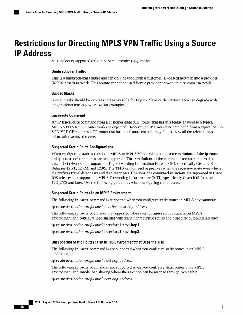
Restrictions for Directing MPLS VPN Traffic Using a SourceIP Address
VRF Select is supported only in Service Provider (-p-) images.
Unidirectional Traffic
This is a unidirectional feature and can only be used from a customer (IP-based) network into a provider(MPLS-based) network. This feature cannot be used from a provider network to a customer network.
Subnet Masks
Subnet masks should be kept as short as possible for Engine 2 line cards. Performance can degrade withlonger subnet masks (/24 or /32, for example).
traceroute Command
An IP traceroute command from a customer edge (CE) router that has this featue enabled to a typicalMPLS VPN VRF CE router works as expected. However, an IP traceroute command from a typical MPLSVPN VRF CE router to a CE router that has this feature enabled may fail to show all the relevant hopinformation across the core.
Supported Static Route Configurations
When configuring static routes in an MPLS or MPLS VPN environment, some variations of the ip routeand ip route vrf commands are not supported. These variations of the commands are not supported inCisco IOS releases that support the Tag Forwarding Information Base (TFIB), specifically Cisco IOSReleases 12.xT, 12.xM, and 12.0S. The TFIB cannot resolve prefixes when the recursive route over whichthe prefixes travel disappears and then reappears. However, the command variations are supported in CiscoIOS releases that support the MPLS Forwarding Infrastructure (MFI), specifically Cisco IOS Release12.2(25)S and later. Use the following guidelines when configuring static routes.
Supported Static Routes in an MPLS Environment
The following ip route command is supported when you configure static routes in MPLS environment:
ip route destination-prefix mask interface next-hop-address
The following ip route commands are supported when you configure static routes in an MPLSenvironment and configure load sharing with static nonrecursive routes and a specific outbound interface:
ip route destination-prefix mask interface1 next-hop1
ip route destination-prefix mask interface2 next-hop2
Unsupported Static Routes in an MPLS Environment that Uses the TFIB
The following ip route command is not supported when you configure static routes in an MPLSenvironment:
ip route destination-prefix mask next-hop-address
The following ip route command is not supported when you configure static routes in an MPLSenvironment and enable load sharing where the next hop can be reached through two paths:
ip route destination-prefix mask next-hop-address
Directing MPLS VPN Traffic Using a Source IP Address Restrictions for Directing MPLS VPN Traffic Using a Source IP Address
MPLS Layer 3 VPNs Configuration Guide, Cisco IOS Release 12.4118

The following ip route command is not supported when you configure static routes in an MPLSenvironment and enable load sharing where the destination can be reached through two next hops:
ip route destination-prefix mask next-hop1
ip route destination-prefix mask next-hop2
Use the interface and next-hop arguments when specifying static routes.
Supported Static Routes in an MPLS VPN Environment
The following ip route vrf commands are supported when you configure static routes in a MPLS VPNenvironment, and the next hop and interface are in the same VRF:
• ◦ ip route vrf vrf-name destination-prefix mask next-hop-address◦ ip route vrf vrf-name destination-prefix mask interface next-hop-address◦ ip route vrf vrf-name destination-prefix mask interface1 next-hop1◦ ip route vrf vrf-name destination-prefix mask interface2 next-hop2
The following ip route vrf commands are supported when you configure static routes in a MPLS VPNenvironment, and the next hop is in the global table in the MPLS cloud in the global routing table. Forexample, these commands are supported when the next hop is pointing to the Internet Gateway.
• ◦ ip route vrf vrf-name destination-prefix mask next-hop-address global◦ ip route vrf vrf-name destination-prefix mask interface next-hop-address (This command is
supported when the next hop and interface are in the core.)
The following ip route commands are supported when you configure static routes in a MPLS VPNenvironment and enable load sharing with static nonrecursive routes and a specific outbound interfaces:
ip route destination-prefix mask interface1 next-hop1
ip route destination-prefix mask interface2 next-hop2
Unsupported Static Routes in an MPLS VPN Environment that Uses the TFIB
The following ip route command is not supported when you configure static routes in a MPLS VPNenvironment, the next hop is in the global table in the MPLS cloud within the core, and you enable loadsharing where the next hop can be reached through two paths:
ip route vrf destination-prefix mask next-hop-address global
The following ip route commands are not supported when you configure static routes in a MPLS VPNenvironment, the next hop is in the global table in the MPLS cloud within the core, and you enable loadsharing where the destination can be reached through two next hops:
ip route vrf destination-prefix mask next-hop1 global
ip route vrf destination-prefix mask next-hop2 global
The following ip route vrf commands are not supported when you configure static routes in an MPLSVPN environment, and the next hop and interface are in the same VRF:
ip route vrf vrf-name destination-prefix mask next-hop1
ip route vrf vrf-name destination-prefix mask next-hop2
Directing MPLS VPN Traffic Using a Source IP AddressRestrictions for Directing MPLS VPN Traffic Using a Source IP Address
MPLS Layer 3 VPNs Configuration Guide, Cisco IOS Release 12.4 119

Supported Static Routes in an MPLS VPN Environment Where the Next Hop Resides in the Global Table onthe CE Router
The following ip route vrf command is supported when you configure static routes in a MPLS VPNenvironment, and the next hop is in the global table on the CE side. For example, the following command issupported when the destination-prefix is the CE router’s loopback address, as in EBGP multihop cases.
ip route vrf vrf-name destination-prefix mask interface next-hop-address
The following ip route commands are supported when you configure static routes in a MPLS VPNenvironment, the next hop is in the global table on the CE side, and you enable load sharing with static non-recursive routes and a specific outbound interfaces:
ip route destination-prefix mask interface1 nexthop1
ip route destination-prefix mask interface2 nexthop2
Information About Directing MPLS VPN Traffic Using aSource IP Address
• Introduction to Directing MPLS VPN Traffic Using a Source IP Address, page 120• How MPLS VPN Traffic Is Routed Using the Source IP Address, page 120• Example of MPLS VPN Traffic Being Routed Based on the Source IP Address, page 121• MPLS VPN Traffic Is Unidirectional, page 122• Advantages of Using the Source IP Address over Per-Interface IP VPN Configuration, page 123• Benefits of Directing MPLS VPN Traffic Using a Source IP Address, page 124
Introduction to Directing MPLS VPN Traffic Using a Source IP AddressThis feature allows packets arriving on an interface to be switched into the appropriate VRF table basedupon the source IP address of the packets. Once the packets have been “selected” into the correct VRFrouting table, they are processed normally based upon the destination address and forwarded through therest of the MPLS VPN.
In most cases, this is a “one way” feature; it works on packets coming from the end users to the PE router.
How MPLS VPN Traffic Is Routed Using the Source IP AddressThis feature uses the following process to route packets from the customer networks to the PE router andinto the provider network.
A two-table lookup mechanism is used at the ingress interface of the PE router to determine the routing andforwarding of packets coming from the customer networks, which use IP protocols, to the MPLS VPNnetworks, which use MPLS protocols.
• The first table, the VRF Selection table, is used to compare the source IP address of the packet with alist of IP addresses in the table. Each IP address in the table is associated with an MPLS VPN. If amatch is found between the source IP address of the packet and an IP address in the VRF Selectiontable, the packet is routed to the second table (the VRF table) or the routing table for the appropriateVPN.
If no match is found in the table for the source IP address of the packet, the packet will either be routed viathe global routing table used by the PE router (this is the default behavior), or will be dropped. See the
Introduction to Directing MPLS VPN Traffic Using a Source IP Address Information About Directing MPLS VPN Traffic Using a Source IP Address
MPLS Layer 3 VPNs Configuration Guide, Cisco IOS Release 12.4120

Configuring a VRF to Eliminate Unnecessary Packet Forwarding Example, page 129 for moreinformation.• The second table, the VRF table (also known as the VPN routing and forwarding table), contains the
virtual routing and forwarding information for the specified VPN and is used to forward the selectedVPN traffic to the correct MPLS label switched path (LSP) based upon the destination IP address ofthe packet.
The VRF Selection process removes the association between the VRF and the interface and allows morethan one MPLS VPN VRF to be associated with the interface.
Example of MPLS VPN Traffic Being Routed Based on the Source IPAddress
An example of this feature is a network carrier that allows subscribers to the carrier to choose frommultiple Internet service providers (ISPs) for Internet access. The figure below provides an example of thisfeature with an IP-based Host network, an MPLS VPN network, and three ISPs connected to the MPLSVPN network.
Figure 5 Implementation Example
Example of MPLS VPN Traffic Being Routed Based on the Source IP AddressInformation About Directing MPLS VPN Traffic Using a Source IP Address
MPLS Layer 3 VPNs Configuration Guide, Cisco IOS Release 12.4 121

In the figure above, Carrier X represents the network carrier; Host A, Host B and Host C represent thecarrier subscribers; and ISP 1, ISP 2 and ISP 3 represent the ISPs.
• PE2 acts as both a VRF selector and a typical MPLS VPN PE router to CE2 and CE3.• ISPs 1 through 3 provide a list of IP addresses to Carrier X so that each host in the “POOL” network
can be properly addressed. This host addressing would most likely be done by using the DHCP orDNS services of Carrier X.
A dashed line represents the path of a packet traveling from Host A to ISP 1. Host A chooses ISP 1 to useas its ISP. Carrier X provides an IP address to Host A that falls within the range of the ISP 1 registerednetwork addresses (1.1.0.0/16). Based upon this IP address allocation, the VRF Selection criteria is set.
By using default routes, hosts on the POOL network (such as Host A), forward traffic from the Carrier XIP-based (POOL) network to the Carrier X MPLS-based VPN network. PE2 has been configured with thisfeature. Therefore, the MPLS VPN network forwards the traffic from Host A to ISP 1.
This is a one-way (unidirectional) feature in most implementations; it only works on packets coming fromthe customer networks to a PE router. Traffic coming from the ISPs to the hosts (in the example, traffictraveling from the ISPs on the right to the hosts on the left) is not affected by this feature and does not haveto be returned via an MPLS path. This traffic can return via the shortest available IP path.
Another example is a Cable Modem Termination System (CMTS). If the owner of the CMTS wants toallow cable modem subscribers to choose their ISP from a group of ISPs, this feature provides a fast andscalable solution.
MPLS VPN Traffic Is UnidirectionalIn the figure above, the end users are typical Internet home users. If this were a two-way (bidirectional)feature, traffic coming from the ISPs to the hosts would be required to use only the PE routers that have thisfeature enabled, which might cause performance issues.
When traffic from the POOL network goes through the Carrier network to the ISP networks for Internetaccess, the traffic in the Carrier network must be forwarded using MPLS VPN paths, because the router has“selected” the traffic into the correct MPLS VPN.
Traffic from the ISP networks to the POOL network does not have to use MPLS VPN paths in the Carriernetwork and can use any path that is most efficient to return to the POOL network. This traffic can use apath that uses either MPLS or IP for routing and forwarding and does not have to travel via an MPLS VPN.
Traffic from the ISP networks to the POOL networks can be forwarded using the global routing table usedby every interface. One way to accomplish this is to enter VRF static routes on the PE router interfacesconnected to the ISPs. The VRF static routes would route traffic from the ISPs to the Carrier network. Seethe Establishing IP Static Routes for a VRF Instance, page 126 for information on placing a default VRFstatic route onto an interface.
Establishing static VRF routes allows traffic from the ISPs to enter the Carrier network as traffic that canonly be routed by using the global routing table toward the POOL network.
If the ISPs do not provide global host address space, or this feature is not being used to route Internettraffic, the PE interfaces connected to the ISPs must be placed into a VRF. If the PE interfaces are usingVRFs for routing traffic from the ISPs, all traffic from the ISPs to the hosts through the Carrier networkwould be forwarded using MPLS VPN paths, and performance would not be as optimal as if IP forwardingwas used.
Normal IP-based VPN operations, such as populating the Routing Information Base (RIB) and ForwardingInformation Base (FIB) from a routing protocol such as Border Gateway Protocol (BGP), are used to routeand forward packets within the various VPNs in the customer networks. The provider network uses MPLS-based routing protocols to perform VPN routing and forwarding inside the provider network.
MPLS VPN Traffic Is Unidirectional Information About Directing MPLS VPN Traffic Using a Source IP Address
MPLS Layer 3 VPNs Configuration Guide, Cisco IOS Release 12.4122

• Conditions That Cause MPLS VPN Traffic To Become Bidirectional, page 123
Conditions That Cause MPLS VPN Traffic To Become BidirectionalForwarding of traffic from the Carrier network to the POOL network by using the global routing table isonly possible if the ISPs have provided registered IP address space for all of the subscribed users within thePOOL network from the global routing table.
If the POOL network uses IP addresses that are not globally routeable and are designed for a nonconnectedenterprise (defined by RFC 1918), this feature becomes bidirectional. All traffic being sent and received bythe host would have to travel via a router that has this feature enabled. The POOL network cannot beaddressed with overlapping address space, regardless of the type of address space being used.
Advantages of Using the Source IP Address over Per-Interface IP VPNConfiguration
This feature removes the association between a VPN and an interface. Before this feature was introduced,the following implementation was used to route outgoing MPLS VPN packets to different destinations:
• A policy-based router (PBR) is attached to the CE router.• The egress side of the PBR router side has VLANs connected to a PE.• The PBR router uses a policy-based route map to select the correct output (VLAN) interface and each
VLAN is under a specific VRF. The figure below illustrates a sample configuration of using a PBRrouter for routing MPLS packets to different destinations.
Figure 6 Implementation of Multiple VPNs
The following limitations apply to PBR-based solutions that use this implementation:
• Policy routing and MPLS VPN functions cannot be performed on the same platform. Integration into asingle platform is critical for manageability and support.
• VRF is limited to one VPN per interface, which limits scalability.• The Cisco 7500 series router is used for the PBR, which can limit network performance.• There is no network redundancy.• The PBR is the only point of connection for all the networks attached to the PBR. The capacity and the
performance capabilities of the PBR router are critical.
Advantages of Using the Source IP Address over Per-Interface IP VPN ConfigurationConditions That Cause MPLS VPN Traffic To Become Bidirectional
MPLS Layer 3 VPNs Configuration Guide, Cisco IOS Release 12.4 123

• There is no diversity in the connectivity to the networks.• Every network is required to connect to every PBR. If every network is not connected to every PBR,
packets from the end user to the PBR would be dropped because the PBR would have no way ofswitching the IP traffic properly.
• Adding multiple PBRs that are interconnected introduces more network policy-routed hops.
This feature addresses the limitations of and problems with using a PBR for packet routing and forwarding.
Benefits of Directing MPLS VPN Traffic Using a Source IP Address
Association of VPN to interface is removed
This feature removes the association between a VPN and an interface, thus allowing packets from the Hostnetwork to the provider network to have more than one VPN available per interface.
Access to every customer network is possible from every PE router in the provider network
Access points to each network can be established at any MPLS PE router, and can be made redundant byconnections to multiple PE routers (for example, the CE2 router in the figure above).
Multiple points in the provider network can be used for VPN routing and forwarding
MPLS VPNs, like IP, are connectionless. Any PE router can carry MPLS VPN traffic from the MPLSnetwork out to the CE routers.
How to Enable MPLS VPN Traffic To Be Routed Using aSource IP Address
• Enabling Routing of MPLS VPN Traffic Based on the Source IP Address, page 124
• Establishing IP Static Routes for a VRF Instance, page 126
Enabling Routing of MPLS VPN Traffic Based on the Source IP AddressPerform the following steps to enable MPLS VPN traffic to be routed based on the source IP address.
SUMMARY STEPS
1. enable
2. configure terminal
3. vrf selection source source-IP-address source-IP-mask vrf vrf-name
4. interface type number
5. ip vrf select source
6. ip vrf receive vrf_namevrf
7. end
8. show ip route vrf
9. show ip vrf select
Benefits of Directing MPLS VPN Traffic Using a Source IP Address How to Enable MPLS VPN Traffic To Be Routed Using a Source IP Address
MPLS Layer 3 VPNs Configuration Guide, Cisco IOS Release 12.4124

DETAILED STEPS
Command or Action Purpose
Step 1 enable
Example:
Router> enable
Enables privileged EXEC mode.
• Enter your password if prompted.
Step 2 configure terminal
Example:
Router# configure terminal
Enters global configuration mode.
Step 3 vrf selection source source-IP-address source-IP-mask vrf vrf-name
Example:
Router(config)# vrf selection source 16.16.0.0 255.255.0.0 vrf vpn1
Populates a source IP address to a VRF selection table.
Step 4 interface type number
Example:
Router(config)# interface FastEthernet 0/1
Configures an interface and enters interfaceconfiguration mode.
Step 5 ip vrf select source
Example:
Router(config-if)# ip vrf select source
Enables an interface to direct MPLS VPN traffic basedon the source IP address of the packet.
Step 6 ip vrf receive vrf_namevrf
Example:
Router(config-if)# ip vrf receive vpn1
Adds all the IP addresses that are associated with aninterface into a VRF table.
Step 7 end
Example:
Router(config-if)# end
(Optional) Exits to privileged EXEC mode.
Directing MPLS VPN Traffic Using a Source IP AddressHow to Enable MPLS VPN Traffic To Be Routed Using a Source IP Address
MPLS Layer 3 VPNs Configuration Guide, Cisco IOS Release 12.4 125

Command or Action Purpose
Step 8 show ip route vrf
Example:
Router# show ip route vrf
Displays the IP routing table associated wtih a VRFinstance. Use this command to verify the configuration.
Step 9 show ip vrf select
Example:
Router# show ip vrf select
Displays information about the VRF selection.
Establishing IP Static Routes for a VRF InstanceTraffic coming from the ISPs to the hosts does not require the use of the MPLS VPN paths; this traffic canuse the shortest IP route back to the host.
VPN static routes for traffic returning to the customer networks are only necessary if VPN traffic returningto the customer networks is being forwarded back from the enabled interface. The remote PE router couldalso be configured to route return traffic to the customer networks directly by using the global routing table.
SUMMARY STEPS
1. enable
2. configure terminal
3. interface type number
4. ip route vrf vrf_name prefix mask [next-hop-address] [interface {interface-number}] [global][distance] [permanent] [tag tag]
DETAILED STEPS
Command or Action Purpose
Step 1 enable
Example:
Router> enable
Enables privileged EXEC mode.
• Enter your password if prompted.
Step 2 configure terminal
Example:
Router# configure terminal
Enters global configuration mode.
Establishing IP Static Routes for a VRF Instance How to Enable MPLS VPN Traffic To Be Routed Using a Source IP Address
MPLS Layer 3 VPNs Configuration Guide, Cisco IOS Release 12.4126

Command or Action Purpose
Step 3 interface type number
Example:
Router(config)# interface FastEthernet 0/1
Configures an interface and enters interfaceconfiguration mode.
Step 4 ip route vrf vrf_name prefix mask [next-hop-address] [interface{interface-number}] [global] [distance] [permanent] [tag tag]
Example:
Router(config-if)# ip route vrf vpn1 16.16.0.0 255.255.0.0 POS1/0
Establishes static routes for a VRF.
• Troubleshooting Tips, page 127
Troubleshooting Tips
• Enter the debug vrf select command to enable debugging for this feature.
Note The debug vrf select command can cause many messages to be logged when you change the configurationand when switching occurs.
• The following error messages appear if problems occur while configuring this feature:
◦ If you attempt to configure a nonexisting VRF Selection table:
Router(config)# vrf selection source 2.0.0.0o 255.255.0.0 vrf VRF_NOEXISTVRF Selection: VRF table VRF_NOEXIST does not exist.
• If you attempt to remove a VRF Selection entry that does not exist:
Router(config)# no vrf selection source 2.0.0.0 255.255.0.0 vrf VRF1VRF Selection: Can't find the node to remove.
• If you attempt to configure a duplicate IP address and subnet mask for a VRF Selection entry:
Router(config)# vrf selection source 2.0.0.0 255.0.0.0 vrf VRF_AOL
Router(config)# vrf selection source 2.0.0.0 255.0.0.0 vrf VRF_AOLVRF Selection: duplicate address and mask configured.
• If an inconsistent IP address and mask are used for a VRF Selection entry:
Router(config)# vrf selection source 170.1.2.1 255.255.255.0 vrf red% Inconsistent address and mask
Router(config)# vrf selection source 170.1.2.1 255.255.255.255 vrf red
Directing MPLS VPN Traffic Using a Source IP AddressTroubleshooting Tips
MPLS Layer 3 VPNs Configuration Guide, Cisco IOS Release 12.4 127

• If you attempt to configure a VRF instance on an interface that has this feature already configured:
Router(config-if)# ip vrf select source
Router(config-if)# ip vrf forward red% Can not configure VRF if VRF Select is already configuredTo enable VRF, first remove VRF Select from the interface
• If you attempt to configure an entry on an interface that has this feature already configured:
Router(config-if)# ip vrf forward red
Router(config-if)# ip vrf select source% Can not configure VRF Select if interface is under a non-global VRFTo enable VRF Select, first remove VRF from the interface
Configuration Examples for Directing MPLS VPN TrafficUsing a Source IP Address
• Enabling MPLS VPN Traffic To Be Routed Based on Source IP Address Example, page 128
• Configuring a VRF to Eliminate Unnecessary Packet Forwarding Example, page 129
• Verifying the Configuration Example, page 129
Enabling MPLS VPN Traffic To Be Routed Based on Source IP AddressExample
The following example defines two entries (vpn1 and vpn2) in the VRF Selection table. In this example,packets with the source address of 16.16.0.0 will be routed to the VRF vpn1, and packets with the sourceaddress of 17.17.0.0 will be routed to the VRF vpn2:
Router(config)# vrf selection source 16.16.0.0 255.255.0.0 vrf vpn1
Router(config)# vrf selection source 17.17.0.0 255.255.0.0 vrf vpn2
The following example creates IP static routes for two VRFs (vpn1 and vpn2) for the POS1/0 interface:
Router(config)# ip route vrf vpn1 16.16.0.0 255.255.0.0 POS1/0
Router(config)# ip route vrf vpn1 17.17.0.0 255.255.0.0 POS1/0
The following example configures the POS1/0 interface for this feature and adds the configured IP address(31.0.0.1) to the VRFs vpn1 and vpn2 as connected routes.
Router(config)# interface POS1/0
Router(config-if)# description Link to CE1 POS1/0 (eng2)
Router(config-if)# ip vrf select source
Router(config-if)# ip vrf receive vpn1
Router(config-if)# ip vrf receive vpn2
Router(config-if)# ip address 31.0.0.1 255.0.0.0
Router(config-if)# no ip directed broadcast
Router(config-if)# load-interval 30
Router(config-if)# crc 32
Router(config-if)# end
Enabling MPLS VPN Traffic To Be Routed Based on Source IP Address Example Configuration Examples for Directing MPLS VPN Traffic Using a Source IP Address
MPLS Layer 3 VPNs Configuration Guide, Cisco IOS Release 12.4128

Configuring a VRF to Eliminate Unnecessary Packet Forwarding ExampleIf a packet arrives at an interface that has VRF Select enabled, and its source IP address does not match anyVRF Select definition, that packet will be forwarded via the global routing table. This default behaviorcould cause problems if IP address spoofing is being implemented. Unnecessary traffic could be forwardedvia the global routing table. To eliminate this unnecessary routing of packets, create a VRF Selectiondefinition that will forward all unknown incoming traffic to a null interface.
The following configuration causes all traffic not matching a more specific VRF Selection definition to berouted to the Null0 interface, thus dropping the packets.
Router(config)# ip vrf VRF_DROP
Router(config-vrf)# rd 999:99
Router(config-vrf)# route-target export 999:99
Router(config-vrf)# route-target import 999:99
Router(config-vrf)# exit
Router(config)# vrf selection source 0.0.0.0 0.0.0.0 vrf VRF_DROP
Router(config)# ip route vrf VRF_DROP 0.0.0.0 0.0.0.0 Null0
Verifying the Configuration ExampleThis example shows the IP routing table associated with the VRF vrf1:
Router# show ip route vrf vpn1Routing Table: vpn1Codes: C - connected, S - static, I - IGRP, R - RIP, M - mobile, B - BGPD - EIGRP, EX - EIGRP external, O - OSPF, IA - OSPF inter areaN1 - OSPF NSSA external type 1, N2 - OSPF NSSA external type 2E1 - OSPF external type 1, E2 - OSPF external type 2, E - EGPi - IS-IS, L1 - IS-IS level-1, L2 - IS-IS level-2, ia - IS-IS inter area* - candidate default, U - per-user static route, o - ODRGateway of last resort is not setB 33.0.0.0/8 [200/0] via 10.10.10.10, 00:00:375.0.0.0/16 is subnetted, 1 subnetsB 5.19.0.0 [200/0] via 10.10.10.10, 00:00:3714.0.0.0/32 is subnetted, 1 subnetsB 14.14.14.14 [200/0] via 10.10.10.10, 00:00:3715.0.0.0/32 is subnetted, 1 subnetsS 15.15.15.15 [1/0] via 34.0.0.1, POS1/1
Additional ReferencesRelated Documents
Related Topic Document Title
Basic MPLS VPNs Configuring MPLS Layer 3 VPNs
MPLS VPN Carrier Supporting Carrier • MPLS VPN Carrier Supporting Carrier UsingLDP and an IGP
• MPLS VPN Carrier Supporting Carrier withBGP
Configuring a VRF to Eliminate Unnecessary Packet Forwarding ExampleAdditional References
MPLS Layer 3 VPNs Configuration Guide, Cisco IOS Release 12.4 129

Related Topic Document Title
MPLS VPN InterAutonomous Systems • MPLS VPN Inter-AS with ASBRs ExchangingIPv4 Routes and MPLS Labels
• MPLS VPN Inter-AS with ASBRs ExchangingVPN-IPv4 Addresses
Standards
Standard Title
No new or modified standards are supported by thisfeature, and support for existing standards has notbeen modified by this feature.
--
MIBs
MIB MIBs Link
No new or modified MIBs are supported by thisfeature, and support for existing MIBs has not beenmodified by this feature.
To obtain lists of supported MIBs by platform andCisco software release, and to download MIBmodules, go to the Cisco MIB website onCisco.com at the following URL:
http://www.cisco.com/public/sw-center/netmgmt/cmtk/mibs.shtml
RFCs
RFC Title
No new or modified RFCs are supported by thisfeature, and support for existing RFCs has not beenmodified by this feature.
--
Directing MPLS VPN Traffic Using a Source IP Address Additional References
MPLS Layer 3 VPNs Configuration Guide, Cisco IOS Release 12.4130

Technical Assistance
Description Link
The Cisco Technical Support website containsthousands of pages of searchable technical content,including links to products, technologies, solutions,technical tips, and tools. Registered Cisco.comusers can log in from this page to access even morecontent.
The Cisco Support website provides extensiveonline resources, including documentation and toolsfor troubleshooting and resolving technical issueswith Cisco products and technologies.
To receive security and technical information aboutyour products, you can subscribe to variousservices, such as the Product Alert Tool (accessedfrom Field Notices), the Cisco Technical ServicesNewsletter, and Really Simple Syndication (RSS)Feeds.
Access to most tools on the Cisco Support websiterequires a Cisco.com user ID and password.
http://www.cisco.com/techsupport
Feature Information for Directing MPLS VPN Traffic Using aSource IP Address
The following table provides release information about the feature or features described in this module.This table lists only the software release that introduced support for a given feature in a given softwarerelease train. Unless noted otherwise, subsequent releases of that software release train also support thatfeature.
Use Cisco Feature Navigator to find information about platform support and Cisco software image support.To access Cisco Feature Navigator, go to www.cisco.com/go/cfn. An account on Cisco.com is not required.
Table 8 Feature Information for Directing MPLS VPN Traffic Using a Source IP Address
Feature Name Releases Feature Configuration Information
VRF Selection Based on SourceIP Address
12.0(22)S
12.0(23)S
12.0(24)S
12.0(26)S
This feature lets you direct MPLSVPN traffic based on the sourceIP address of the packet.
Cisco and the Cisco logo are trademarks or registered trademarks of Cisco and/or its affiliates in the U.S.and other countries. To view a list of Cisco trademarks, go to this URL: www.cisco.com/go/trademarks.
Directing MPLS VPN Traffic Using a Source IP AddressFeature Information for Directing MPLS VPN Traffic Using a Source IP Address
MPLS Layer 3 VPNs Configuration Guide, Cisco IOS Release 12.4 131

Third-party trademarks mentioned are the property of their respective owners. The use of the word partnerdoes not imply a partnership relationship between Cisco and any other company. (1110R)
Any Internet Protocol (IP) addresses and phone numbers used in this document are not intended to beactual addresses and phone numbers. Any examples, command display output, network topology diagrams,and other figures included in the document are shown for illustrative purposes only. Any use of actual IPaddresses or phone numbers in illustrative content is unintentional and coincidental.
Directing MPLS VPN Traffic Using a Source IP Address
MPLS Layer 3 VPNs Configuration Guide, Cisco IOS Release 12.4132