mpls-thesis2013.pdf
DESCRIPTION
MPLS configuration. deployment methods for basic and large scale enterprise...TRANSCRIPT

Anas Al-Selwi
Multiprotocol Label Switching Virtual Private Network
Helsinki Metropolia University of Applied Sciences
Bachelor of Engineering
Information Technology
Thesis
08 May 2013

Abstract
Author(s) Title Number of Pages Date
Anas Al-Selwi Multiprotocol Label Switching Virtual Private Network 41 pages + 3 appendices 08 May 2013
Degree Bachelor of Engineering
Degree Programme Information Technology
Specialisation option Computer Networks and Security
Instructor
Erik Pätynen, Senior Lecturer
A Service provider network must have the capability of facing the challenge of customer demands, especially when there are thousands or even tens of thousands of customer traffic to be carried within a single network infrastructure. Also there must be some solu-tions to provide new services that are not supported within the service provider network. A conventional IP lookup process and forwarding do not scale well and there must be some ways for fast lookup and packet forwarding This thesis aimed to present and implement the technology that would allow the service provider to face this challenge and have the capability to serve new services that are not supported within his network infrastructure. In the service provider network, every cus-tomer or service is represented by an MPLS VPN and it is completely independent. Moreover, the thesis introduced some advanced MPLS topologies, an intranet where cus-tomer sites are connected through a central site, an extranet where various customer sites are connected to each other and central services where a central server can be deployed to serve a specific customer, various customers or it can be connected to the Internet. In addition, inter-autonomous MPLS VPN, where customer sites are connected over multiple service providers, AToM and VPLS are briefly presented. The MPLS VPN theory and implementations provided in this thesis are applied to Cisco routers only. Different vendors have different implementations, for example in MPLS, Cisco requires enabling MPLS in the interface mode. However, some vendors require enabling it in the global configuration mode even though the concept of MPLS is the same in every vendor.
Keywords MPLS, MPLS VPN
Contents
1 Introduction 1
2 MPLS and Label Distribution 2
2.1 MPLS Basics 2
2.2 MPLS Label, Label Stack and Label Operations 5
2.3 Label Distribution Protocol and MPLS Operation 7
2.4 Label-Switched Path 10
2.5 CEF Switching 11
2.5.1 CEF Switching Mechanisms 11
2.5.2 CEF Configuration 11
2.6 Basic MPLS and LDP Configurations 12
3 MPLS VPN Architecture 13
3.1 Overview 13
3.2 Simple MPLS VPN Model 14
3.3 Virtual Routing and Forwarding 15
3.4 Route Distinguisher 16
3.5 Route Targets 17
3.6 PE-to-CE Connectivity 19
3.6.1 PE-to-CE Connectivity – Static Routing 19
3.6.2 PE-to-CE Connectivity – RIP Version 2 20
3.6.3 PE-to-CE Connectivity – eBGP 21
3.7 Interface Association to a VRF 22
3.8 Route Propagation in an MPLS VPN Network 22
3.9 Multiprotocol BGP 23
3.9.1 Overview of MP-BGP 23
3.9.2 Multiprotocol BGP Configuration 23
3.10 MPLS VPN Site Expansion 24
3.11 MPLS VPN Example 25
3.12 Testing an MPLS VPN Network 26
3.13 Advanced MPLS VPN Topologies 30
3.13.1 Intranet and Extranet Example 30
3.13.2 Central Services Topology 32
3.14 Inter-autonomous MPLS VPN 34
4 Introduction to AToM and VPLS 36
4.1 Any Transport over MPLS 36
4.1.1 Overview of AToM 36
4.1.2 Ethernet over MPLS (EoMPLS) 38
4.2 VPLS 39
5 Conclusion 39
References 41
Appendices
Appendix 1: MPLS VPN Example
Appendix 2: Central Services Topology - Example
Appendix 3: Inter-autonomous MPLS VPN Example
1
1 Introduction
There are many topics that can be presented in MPLS such as MPLS VPN, Traffic En-
gineering, Any Transport over MPLS (AToM – L2 MPLS VPN), QoS and Security.
However, the aim of this thesis is to present and implement MPLS VPN or L3 MPLS
VPN which is actually the platform for all the services provided by a service provider
since every customer or service (such as VoIP or hosting) is represented as an MPLS
VPN.
Two types of MPLS VPN will be discussed and implemented in Cisco routers, MPLS
VPN in a single service provider and inter-autonomous MPLS VPN (MPLS VPN over
multiple service providers). In addition, some advanced MPLS VPN topologies will be
discussed such as intranet, extranet, and central services. L2 MPLS VPNs (AToM and
Virtual Private LAN Service VPLS) will be briefly introduced.
Communication between computers is built through layers, layer 1 to 7, as defined in
the OSI model. The same methodology is applied in MPLS so that at the end we have
an intelligent network. To build MPLS VPN, one of the requirements is that we need a
network infrastructure which means the network must be converged. This is the under-
neath layer. When an MPLS VPN is built, we actually created an incomplete network
that is not application-aware. So we need to continue with the MPLS model, so that in
the end we will reach the application layer.
The thesis is meant for students who already have CCNP knowledge. In the beginning
MPLS technology will be introduced, the reasons behind it and the basic configuration
that will allow us to carry on for the implementation of MPLS VPN networks. The im-
plementations and naming provided do not represent any company. However, they are
given as examples.
Having read this thesis, a student should be able to implement his/her own MPLS VPN
network and have a good knowledge of L2 MPLS VPN.
2
2 MPLS and Label Distribution
2.1 MPLS Basics
In traditional IP routing, packets are forwarded to destination networks based on layer 3
routing information of packet header and the routing table, and routing lookups are
made independently by every router in the network. In service provider network, tradi-
tional IP routing has some issues of network scalability and routing lookups overhead.
So there was a demand to a high speed packet forwarding mechanism. MPLS forwards
packets based on labels (4-byte identifier) which correspond to the destination net-
works which reduces the overhead of traditional IP routing lookups on MPLS core
routers as well as it supports protocols or services that are not supported by the service
provider network.
MPLS runs on top of the IP network infrastructure which means that the network rout-
ing tables must be converged and every router must have a route to any destination
network in the service provider network or MPLS domain. Any IGP routing protocol (IS-
IS, OSPF, EIGRP, RIP or static) can be configured before deploying MPLS.
There are multiple applications supported by MPLS such as unicast and multicast rout-
ing, Virtual Private Network (VPN), Traffic Engineering (TE), Quality of Service (QoS)
and Any Transport over MPLS (AToM). [1]
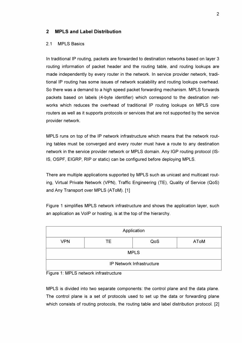
Figure 1 simplifies MPLS network infrastructure and shows the application layer, such
an application as VoIP or hosting, is at the top of the hierarchy.
Application
VPN TE QoS AToM
MPLS
IP Network Infrastructure
Figure 1: MPLS network infrastructure
MPLS is divided into two separate components: the control plane and the data plane.
The control plane is a set of protocols used to set up the data or forwarding plane
which consists of routing protocols, the routing table and label distribution protocol. [2]
3
Exchange of
Routing
Information
Exchange of
labels
Outgoing IP and
Labeled Packets Incoming IP
Packets
Outgoing IP and
Labeled Packets
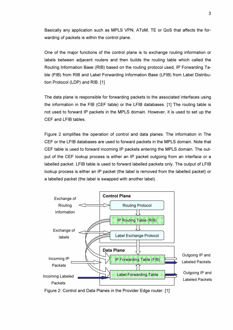
Basically any application such as MPLS VPN, AToM, TE or QoS that affects the for-
warding of packets is within the control plane.
One of the major functions of the control plane is to exchange routing information or
labels between adjacent routers and then builds the routing table which called the
Routing Information Base (RIB) based on the routing protocol used, IP Forwarding Ta-
ble (FIB) from RIB and Label Forwarding Information Base (LFIB) from Label Distribu-
tion Protocol (LDP) and RIB. [1]
The data plane is responsible for forwarding packets to the associated interfaces using
the information in the FIB (CEF table) or the LFIB databases. [1] The routing table is
not used to forward IP packets in the MPLS domain. However, it is used to set up the
CEF and LFIB tables.
Figure 2 simplifies the operation of control and data planes. The information in The
CEF or the LFIB databases are used to forward packets in the MPLS domain. Note that
CEF table is used to forward incoming IP packets entering the MPLS domain. The out-
put of the CEF lookup process is either an IP packet outgoing from an interface or a
labelled packet. LFIB table is used to forward labelled packets only. The output of LFIB
lookup process is either an IP packet (the label is removed from the labelled packet) or
a labelled packet (the label is swapped with another label).
Figure 2: Control and Data Planes in the Provider Edge router. [1]
Incoming Labeled
Packets
Control Plane
Routing Protocol
IP Routing Table (RIB)
Label Exchange Protocol
Data Plane
Label Forwarding Table
IP Forwarding Table (FIB)

4
Now let us see how CEF and LFIB tables look like. At this point, there is no need to be
concerned with the information provided in those tables. A global CEF table can be
shown with command show ip cef as follows:
PE1#show ip cef
Prefix Next Hop Interface
0.0.0.0/0 drop Null0 (def ault route handler entry)
0.0.0.0/32 receive
10.0.0.0/30 attached FastEthern et0/0
10.0.0.0/32 receive
10.0.0.1/32 receive
10.0.0.2/32 10.0.0.2 FastEthern et0/0
10.0.0.3/32 receive
10.0.0.4/30 10.0.0.2 FastEthern et0/0
10.0.0.8/30 10.0.0.2 FastEthern et0/0
10.0.0.201/32 receive
10.0.0.202/32 10.0.0.2 FastEthern et0/0
224.0.0.0/4 drop
224.0.0.0/24 receive
255.255.255.255/32 receive
The show ip cef command does not show information concerning labelled packets.
So we need to specify the destination network with command show ip cef desti-
nation- Ip-prefix {detail } as follows:
PE1#show ip cef 10.0.0.202
10.0.0.202/32, version 13, epoch 0, cached adjacenc y 10.0.0.2
0 packets, 0 bytes
tag information set
local tag: 18
fast tag rewrite with Fa0/0, 10.0.0.2, tags imp osed: {18}
via 10.0.0.2, FastEthernet0/0, 0 dependencies
next hop 10.0.0.2, FastEthernet0/0
valid cached adjacency
tag rewrite with Fa0/0, 10.0.0.2, tags imposed: {18}
LFIB table can be shown with command show mpls forwarding-table {IP-
address or destination-network }. Using the IP-address becomes handy espe-
cially in a production network with thousands of entries either in the CEF or LFIB table.
Sample of LFIB table:
PE1#show mpls forwarding-table
Local Outgoing Prefix Bytes tag Out going Next Hop
tag tag or VC or Tunnel Id switched int erface
16 Pop tag 10.0.0.4/30 0 Fa0 /0 10.0.0.2

5
17 16 10.0.0.8/30 0 Fa0 /0 10.0.0.2
18 18 10.0.0.202/32 0 Fa0 /0 10.0.0.2
PE1#show mpls forwarding-table 10.0.0.202
Local Outgoing Prefix Bytes tag Out going Next Hop
tag tag or VC or Tunnel Id switched int erface
18 18 10.0.0.202/32 0 Fa0 /0 10.0.0.2
The information contained in the LFIB and CEF tables will be clarified later within this
chapter.
2.2 MPLS Label, Label Stack and Label Operations
MPLS label is 32 bits (4 bytes) identifier that has a similar usage as the destination IP
address. Core routers in MPLS domain use the label to identify the destination node
and make forwarding decisions. In addition, the label can be used to identify a service
in the destination note such as a VPN. An MPLS label is equivalent to an FEC (Cisco
Equivalence Class) which defined by Cisco as “a group of packets forwarded in the
same manner, over the same path and with the same forwarding treatment”. An FEC
defines a destination network (typically a next-hop IP address of a BGP neighbor). [1]
The label consists of four fields as shown in Figure 3:
1. Label: 20 bits number used for forwarding decisions.
2. EXP: 3 bits experimental field used to support QoS.
3. 1 bit bottom-of-stack identifier ( 0 indicates that there are more than one label
attached to the packet, 1 indicates that this is the last label)
4. TTL: Similar to TTL value of IP header. [1]
LABEL EXP S TTL
1 19 20 22 23 24 31
Figure 3: Label format. [1]
In an IP packet, the label is pushed between L2 and L3 headers. The L2 protocol iden-
tifier (PID) or Ethertype value is also replaced with a number as an indication of a la-
belled packet. [1] The label switch router LSR examines PID or Ethertype value to iden-
tify if a packet is an IP packet or a labelled packet. The label is also called a shim
header. Figure 4 shows the shim header in an IP packet.
6
Frame Header Label IP Header Payload
L2 Shim header L3
Figure 4: Shim Header
There are three label operations in the MPLS domain:
1. Push (or impose) label on the ingress router which insert a label or label stack
to an IP packet incoming to the MPLS domain.
2. Swap label to the next-hop label in the MPLS core.
3. Pop label on the egress router outgoing from MPLS domain. [1]
Penultimate hop popping (PHP) is a mechanism to reduce one lookup process at the
destination LSR by popping the label one hop before. [1] When a labelled packet is
received to a destination LSR, two lookup processes take place. One lookup takes
place in the LFIB table to pop the label and a second IP lookup in the routing table to
forward the IP packet. PHP pops the label one hop earlier and then forwards the
packet as an IP packet to the destination LSR. At the destination LSR, only an IP
lookup process takes place. PHP is activated by default in Cisco routers and has an
effect in the LFIB table as we are going to see later.
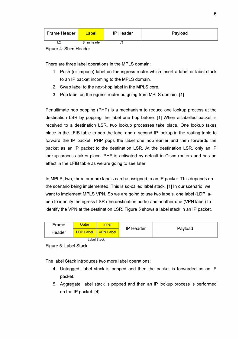
In MPLS, two, three or more labels can be assigned to an IP packet. This depends on
the scenario being implemented. This is so-called label stack. [1] In our scenario, we
want to implement MPLS VPN. So we are going to use two labels, one label (LDP la-
bel) to identify the egress LSR (the destination node) and another one (VPN label) to
identify the VPN at the destination LSR. Figure 5 shows a label stack in an IP packet.
Outer Inner Frame
Header LDP Label VPN Label IP Header Payload
Label Stack
Figure 5: Label Stack
The label Stack introduces two more label operations:
4. Untagged: label stack is popped and then the packet is forwarded as an IP
packet.
5. Aggregate: label stack is popped and then an IP lookup process is performed
on the IP packet. [4]
7
2.3 Label Distribution Protocol and MPLS Operation
Every label switching router LSR in the MPLS domain creates its label locally and then
binds it to an IPv4 prefix. The bindings are then distributed to all LDP neighbours by
LDP. The neighbours then store the local and received neighbour bindings in the label
information base (LIB). The LSR uses the received neighbour binding information and
the routing table to build the label forwarding information base (LFIB) where the local
binding is used as an incoming label and the received binding, that its route listed in the
routing table, is used as an outgoing label. When LFIB is built and a labelled packet is
received, the LSR is able to swap the local label that is assigned locally with the outgo-
ing label that is assigned by the next-hop neighbour. Figure 6 simplifies label bindings
and shows the local and received bindings of the IPv4 network prefix 10.0.0.0/8 redis-
tributed by LDP. Basically, the binding is to associate the label to the IPv4 network pre-
fix. [2] The command show mpls ldp bindings shows the contents of the LIB
table as follows:
PE1#show mpls ldp bindings
tib entry: 10.0.0.0/30, rev 2
local binding: tag: imp-null
remote binding: tsr: 10.0.0.5:0, tag: imp-null
tib entry: 10.0.0.4/30, rev 6
local binding: tag: 16
remote binding: tsr: 10.0.0.5:0, tag: imp-null
tib entry: 10.0.0.8/30, rev 8
local binding: tag: 17
remote binding: tsr: 10.0.0.5:0, tag: 17
tib entry: 10.0.0.201/32, rev 4
local binding: tag: imp-null
remote binding: tsr: 10.0.0.5:0, tag: 16
tib entry: 10.0.0.202/32, rev 10
local binding: tag: 18
remote binding: tsr: 10.0.0.5:0, tag: 18
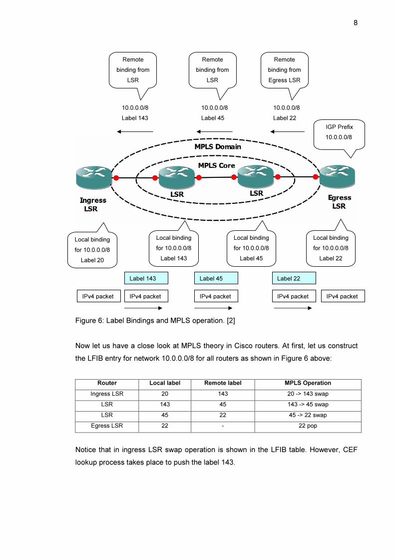
Figure 6 also simplifies the operation of MPLS. When an IPv4 packet is entering the
MPLS domain with destination IPv4 prefix 10.0.0.0/8, the ingress LSR (It is also called
Provider Edge PE) imposes or pushes a 143 label and the forwards the packet to LSR.
The LSR (It is also called Provider P) swaps the incoming label 143 with the outgoing
label 45 and then forwards the packet to the other LSR. The other LSR swaps incom-
ing label 45 with the outgoing label 22 and so on. When the packet is received by
egress LSR (it is also called PE), the label is popped, an IP lookup is performed and
then the packet is forwarded to its destination. [2]
8
Figure 6: Label Bindings and MPLS operation. [2]
Now let us have a close look at MPLS theory in Cisco routers. At first, let us construct
the LFIB entry for network 10.0.0.0/8 for all routers as shown in Figure 6 above:
Router Local label Remote label MPLS Operation
Ingress LSR 20 143 20 -> 143 swap
LSR 143 45 143 -> 45 swap
LSR 45 22 45 -> 22 swap
Egress LSR 22 - 22 pop
Notice that in ingress LSR swap operation is shown in the LFIB table. However, CEF
lookup process takes place to push the label 143.
Remote
binding from
LSR
Remote
binding from
LSR
Remote
binding from
Egress LSR
10.0.0.0/8
Label 143
10.0.0.0/8
Label 45
10.0.0.0/8
Label 22
IGP Prefix
10.0.0.0/8
Local binding
for 10.0.0.0/8
Label 20
Local binding
for 10.0.0.0/8
Label 143
Local binding
for 10.0.0.0/8
Label 45
Local binding
for 10.0.0.0/8
Label 22
Label 22 Label 45 Label 143
IPv4 packet IPv4 packet IPv4 packet IPv4 packet IPv4 packet
9
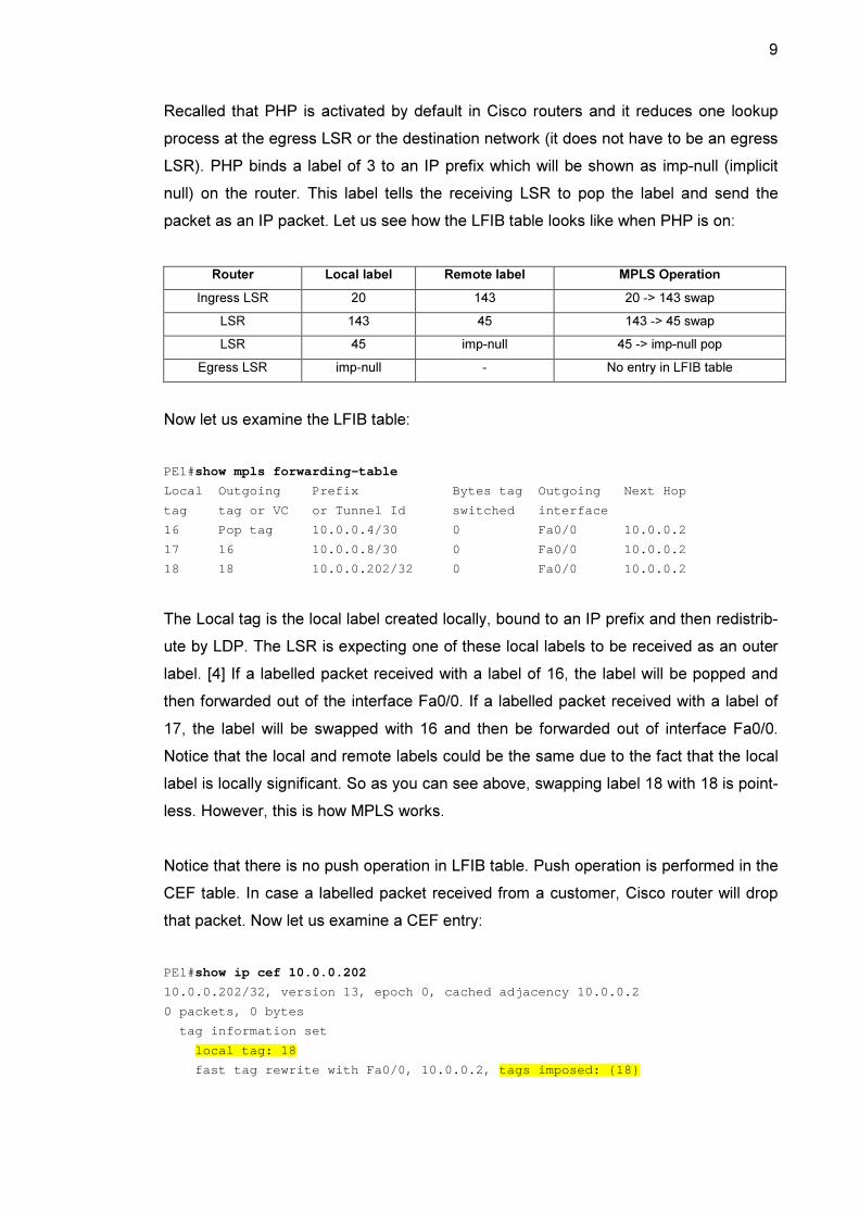
Recalled that PHP is activated by default in Cisco routers and it reduces one lookup
process at the egress LSR or the destination network (it does not have to be an egress
LSR). PHP binds a label of 3 to an IP prefix which will be shown as imp-null (implicit
null) on the router. This label tells the receiving LSR to pop the label and send the
packet as an IP packet. Let us see how the LFIB table looks like when PHP is on:
Router Local label Remote label MPLS Operation
Ingress LSR 20 143 20 -> 143 swap
LSR 143 45 143 -> 45 swap
LSR 45 imp-null 45 -> imp-null pop
Egress LSR imp-null - No entry in LFIB table
Now let us examine the LFIB table:
PE1#show mpls forwarding-table
Local Outgoing Prefix Bytes tag Out going Next Hop
tag tag or VC or Tunnel Id switched int erface
16 Pop tag 10.0.0.4/30 0 Fa0 /0 10.0.0.2
17 16 10.0.0.8/30 0 Fa0 /0 10.0.0.2
18 18 10.0.0.202/32 0 Fa0 /0 10.0.0.2
The Local tag is the local label created locally, bound to an IP prefix and then redistrib-
ute by LDP. The LSR is expecting one of these local labels to be received as an outer
label. [4] If a labelled packet received with a label of 16, the label will be popped and
then forwarded out of the interface Fa0/0. If a labelled packet received with a label of
17, the label will be swapped with 16 and then be forwarded out of interface Fa0/0.
Notice that the local and remote labels could be the same due to the fact that the local
label is locally significant. So as you can see above, swapping label 18 with 18 is point-
less. However, this is how MPLS works.
Notice that there is no push operation in LFIB table. Push operation is performed in the
CEF table. In case a labelled packet received from a customer, Cisco router will drop
that packet. Now let us examine a CEF entry:
PE1#show ip cef 10.0.0.202
10.0.0.202/32, version 13, epoch 0, cached adjacenc y 10.0.0.2
0 packets, 0 bytes
tag information set
local tag: 18
fast tag rewrite with Fa0/0, 10.0.0.2, tags imp osed: {18}

10
via 10.0.0.2, FastEthernet0/0, 0 dependencies
next hop 10.0.0.2, FastEthernet0/0
valid cached adjacency
tag rewrite with Fa0/0, 10.0.0.2, tags imposed: {18}
The command shows that any IP packet destined to the destination IP address
10.0.0.202 will be imposed with a label of 18 and then be forwarded via the next hop
10.0.0.2 out of interface FastEthernet 0/0. The local label 18 is the same as the remote
label in this example.
Now let us examine the LFIB table when a label stack is used:
PE1#show mpls forwarding-table
Local Outgoing Prefix Bytes tag Out going Next Hop
tag tag or VC or Tunnel Id switched int erface
16 Pop tag 192.168.0.0/30 0 Fa0 /0 192.168.0.17
17 16 192.168.0.20/30 0 Fa0 /0 192.168.0.17
18 17 192.168.0.4/30 0 Fa0 /0 192.168.0.17
19 Pop tag 192.168.0.12/30 0 Fa0 /0 192.168.0.17
20 18 192.168.0.202/32 0 Fa0 /0 192.168.0.17
21 20 192.168.0.8/30 0 Fa0 /0 192.168.0.17
22 21 192.168.0.24/30 0 Fa0 /0 192.168.0.17
23 22 192.168.0.28/30 0 Fa0 /0 192.168.0.17
24 23 192.168.0.205/32 0 Fa0 /0 192.168.0.17
25 Aggregate 10.10.10.0/30[V] 0
26 Untagged 172.16.0.0/24[V] 0 Fa0 /1 10.10.10.2
27 Aggregate 10.10.10.4/30[V] 5544
28 Untagged 172.16.0.0/24[V] 0 Fa1 /0 10.10.10.6
Any labelled packet received with a label of 26, the label stack will be removed and the
IP packet will be forwarded via the next hop address 10.10.10.2 out of interface Fa0/1.
If a labelled packet received with a label of 25, the label stack will be removed and an
IP lookup is performed. Network 10.10.10.0/30 is directly connected.
2.4 Label-Switched Path
MPLS provides connection-oriented forwarding between Provider Edge routers. Each
PE has one LSP to any other PE router in the MPLS domain. The LSP is the path
across the MPLS domain that labelled packets of a specific FEC traverse through. The
LSP contains many FECs which basically a set of grouped-labelled packets destined to
many destination networks at the egress LSR. [1]
11
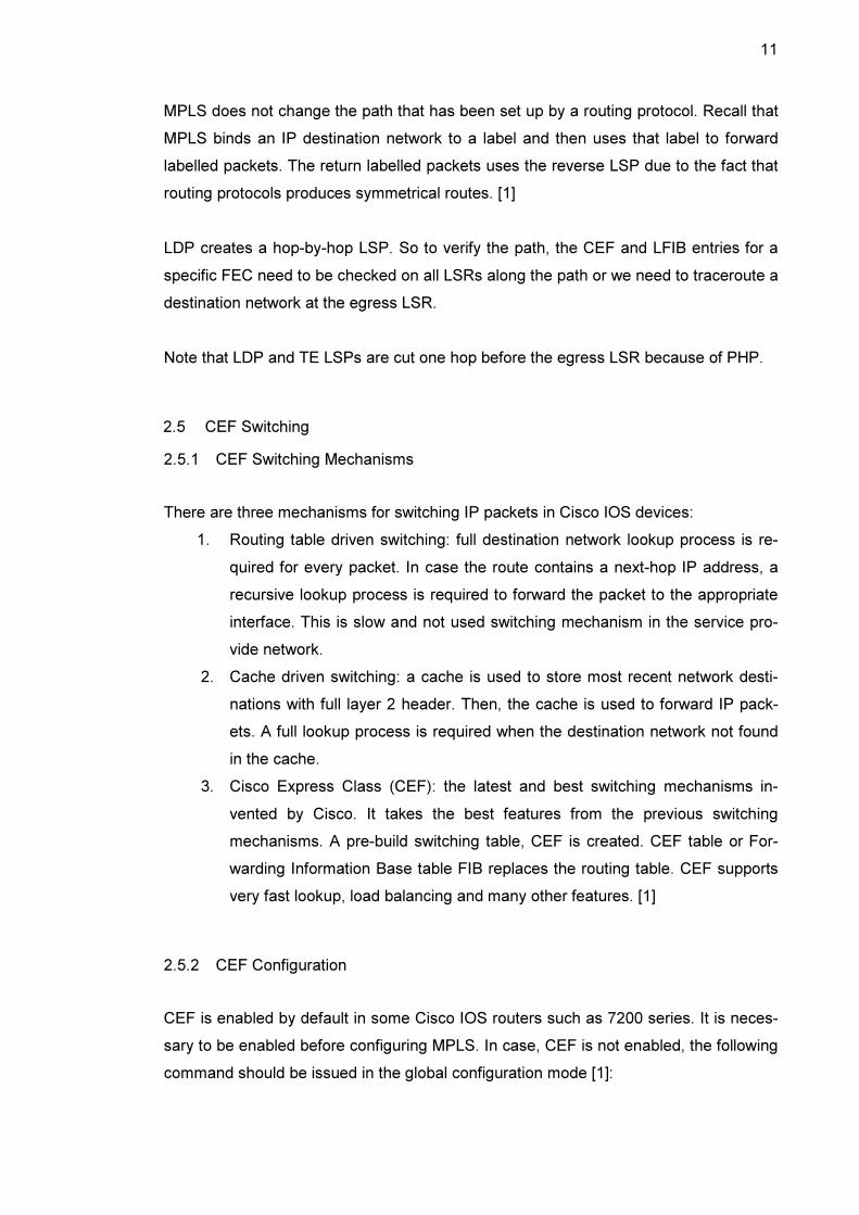
MPLS does not change the path that has been set up by a routing protocol. Recall that
MPLS binds an IP destination network to a label and then uses that label to forward
labelled packets. The return labelled packets uses the reverse LSP due to the fact that
routing protocols produces symmetrical routes. [1]
LDP creates a hop-by-hop LSP. So to verify the path, the CEF and LFIB entries for a
specific FEC need to be checked on all LSRs along the path or we need to traceroute a
destination network at the egress LSR.
Note that LDP and TE LSPs are cut one hop before the egress LSR because of PHP.
2.5 CEF Switching
2.5.1 CEF Switching Mechanisms
There are three mechanisms for switching IP packets in Cisco IOS devices:
1. Routing table driven switching: full destination network lookup process is re-
quired for every packet. In case the route contains a next-hop IP address, a
recursive lookup process is required to forward the packet to the appropriate
interface. This is slow and not used switching mechanism in the service pro-
vide network.
2. Cache driven switching: a cache is used to store most recent network desti-
nations with full layer 2 header. Then, the cache is used to forward IP pack-
ets. A full lookup process is required when the destination network not found
in the cache.
3. Cisco Express Class (CEF): the latest and best switching mechanisms in-
vented by Cisco. It takes the best features from the previous switching
mechanisms. A pre-build switching table, CEF is created. CEF table or For-
warding Information Base table FIB replaces the routing table. CEF supports
very fast lookup, load balancing and many other features. [1]
2.5.2 CEF Configuration
CEF is enabled by default in some Cisco IOS routers such as 7200 series. It is neces-
sary to be enabled before configuring MPLS. In case, CEF is not enabled, the following
command should be issued in the global configuration mode [1]:

12
Router(config)# ip cef
This command enables CEF globally and creates the FIB table. In case, a CEF is re-
quired to be enabled on an interface, then CEF should be globally disabled by com-
mand no ip cef and the following command should be issued [1]:
Router(config-if)# ip route-cache cef
2.6 Basic MPLS and LDP Configurations
There are two compulsory configuration tasks that must be enabled before configuring
MPLS on a LSR [1]:
1. CEF as shown earlier
2. LDP
To enable LDP on a LSR, the following command must be issued in the interface con-
figuration mode [1]:
Router(config-if)# mpls label protocol ldp
This command starts LDP on the selected interface. Then, enable MPLS by command:
Router(config-if)# mpls ip
This command enables IPv4 label switching packets on the selected interface. [1]
These are the basic MPLS commands needed to demonstrate MPLS VPN. There are
still optional commands that can be configured such as MPLS ID, IP TTL propagation
and MTU size for labelled packets. [1]
Note that LDP and MPLS configuration commands must not be issued on the interface
that is connected to the Customer Equipment (CE). These commands must be only
issued within the MPLS domain.
13
3 MPLS VPN Architecture
3.1 Overview
A VPN is a network that represents a private network over the service provider network
infrastructure. The VPN can be implemented in Layer 2 or 3 of the OSI model. Layer 3
MPLS VPN is called MPLS VPN and Layer 2 MPLS VPN is called Any Transport over
MPLS (AToM) in Cisco. The VPN usually belongs to a customer or a company and
might have several customer sites interconnected over the service provider network.
Early VPN networks connectivity was implemented using dedicated point-to-point links
or leased lines which results to high cost to the customer side since the leased line can
not be shared between customers and also it requires a dedicated router port resulting
to high equipment cost to the service provider side. [1]
VPN was introduced to replace dedicated point-to-point links which has the capability
to share a network infrastructure between customers and also being cost-effective to
the customer and the service provider. [1]
There were two VPN scenarios offered by the service provider:
1. Overlay VPNs: the service provider connects the customer sites using virtual
point-to-point links (virtual circuits). As more customer sites connect to the ser-
vice provider network, this leads to scalability issues.
2. Peer-to-Peer VPNs: were introduced to resolve the scalability issues of overlay
VPNs and also to provide fast data transport over the service provider network.
The service provider participates in customer routing which results to optimum
routing. As more customer sites connect to the service provider network, packet
filters were introduced to distinguish customer sites and also results to huge
routing tables to the service provider side which makes monitoring and trouble-
shooting very complex. [1]
In an MPLS VPN network, Provider Edge routers participate in customer routing and
keep separate virtual forwarding table for each customer site. As a result, customers
can use the same network prefix. In other words, the MPLS VPN combines the best
features of the overlay VPNs and the Peer-to-Peer VPNs. [1]

14
MPLS VPN provides connectivity for customer sites over the MPLS domain as a VPN
and also has the capability to connect different VPNs and even provide connectivity to
the internet.
3.2 Simple MPLS VPN Model
It is important to be familiar with MPLS VPN functionality and terminologies used be-
fore any implementation to be introduced. In this section, we are going to present a
simple model of MPLS VPN. Figure 7 shows a simple MPLS VPN model.
Figure 7: MPLS VPN
The service provider network infrastructure consists of two elements:
1. Provider Edge router (PE): It is connected directly to Customer Equipment CE
at Layer 3. Also it runs MPLS and LDP on the interface connected to the P
router so that labels are imposed and then get forwarded.
2. Provider router (P): It has no direct connection to CE and it runs MPLS and
LDP. [2]
The CE is connected at Layer 3 to PE. Therefore, a routing protocol or static routing is
implemented between them since there is no need to implement MPLS.
Every customer site is represented in the service provider as an MPLS VPN as shown
in figure 7 above. Since it is a private network, the customer is allowed to use public or
private IP addresses. The IP addresses used can be overlapping since each VPN has
its own forwarding table in the service provider network. The VPN forwarding table is
located only in the PE routers and it has the same format as the routing table. [2]

15
Multiprotocol BGP is the protocol used to carry customer routes between PE routers. P
routers are unaware of the existence of VPNs. They just forward packets based on
labels (swap labels).
MPLS VPN consists of some building blocks of configuration to be implemented. Those
building blocks are: Virtual Routing and Forwarding table (VRF), Route Distinguisher
(RD), Route Targets (RTs), route propagation through Multiprotocol BGP and forward-
ing of labelled packets. All configuration commands will be issued in the PE routers.
To implement MPLS VPN, there are some steps to follow:
1. Define and configure VRF
2. Define and configure RD
3. Define and configure import and export polices
4. Configure the PE-to-CE links
5. Associate the CE interfaces of the PE with the previously defined VRFs
6. Configure Multiprotocol BGP. [3]
3.3 Virtual Routing and Forwarding
VRF is a routing and forwarding table instance similar to the Cisco IOS routing table.
However, VRF is associated to a single VPN or a customer and contains routes of that
specific VPN due to the fact that the routing must be private and separated from other
VPNs. The PE interface connected to a CE belongs to only one VPN and it is not pos-
sible to configure two VPNs in one interface. [2]
To create VRF, the command ip vrf VPN-name is used and it must be assigned to
the PE interface associated to CE by command ip vrf forwarding VPN-name .
Note that a VRF can be assigned to one interface. However, many interfaces can be
assigned to a VRF. [2]
There are attributes that must be configured in the VRF table and we will have a close
look at these attributes in section 3.4 and 3.5. However, let us present a sample con-
figuration of VRF and how VRF looks like as shown in Example 1.

16
Example 1: VRF Configuration
There is also CEF table for Metropolia VRF and can be shown by command show ip
cef vrf Metropolia .
3.4 Route Distinguisher
In an MPLS VPN network, customer routes are carried by Multiprotocol BGP. As there
are thousands of customers served by the service provider network, IP addresses may
overlap. If customers had overlapping IP addresses, the routing would be wrong. This
problem is solved by the concept of Route Distinguisher (RD) to make IPv4 prefixes
unique. The RD is just a unique identifier (64-bit) used to distinguish IP addresses from
!
ip vrf Metropolia
rd 1:2
route-target export 1:2
route-target import 1:2
!
Interface FastEthernet0/1
Ip vrf forwarding Metropolia
ip address 10.10.10.1 255.255.255.252
!
PE1#show ip route vrf Metropolia
Routing Table: Metropolia
Codes: C - connected, S - static, R - RIP, M - mobi le, B - BGP
D - EIGRP, EX - EIGRP external, O - OSPF, IA - OSPF inter area
N1 - OSPF NSSA external type 1, N2 - OSPF NS SA external type 2
E1 - OSPF external type 1, E2 - OSPF externa l type 2
i - IS-IS, su - IS-IS summary, L1 - IS-IS le vel-1, L2 - IS-IS level-2
ia - IS-IS inter area, * - candidate default , U - per-user static route
o - ODR, P - periodic downloaded static rout e
Gateway of last resort is not set
172.16.0.0/24 is subnetted, 2 subnets
S 172.16.0.0 [1/0] via 10.10.10.2, FastEthern et0/1
B 172.16.1.0 [200/0] via 192.168.0.252, 00:02 :19
10.0.0.0/30 is subnetted, 2 subnets
B 10.20.20.0 [200/0] via 192.168.0.252, 00:02 :19
C 10.10.10.0 is directly connected, FastEther net0/1
17
various customers. A vpnv4 prefix is created from the IPv4 prefix and the RD. MP-BGP
propagates these vpnv4 prefixes between the PE routers. [2]
Note that the RD is used to make VRF IPv4 addresses unique when propagated with
MP-BGP. However, RD does not indicate which VRF the IPv4 addresses belongs to. In
other words, The RD does not indicate the VPN due to the fact that there are complex
MPLS VPN topologies that require more than one RD per VPN. [2]
There must be at least one RD assigned to a VRF instance on the PE router. The for-
mat of RD is ASN:nn or IP-address:nn, where ANS stands for Autonomous System
Number of the service provider and nn is just a number. [2]
The vpnv4 prefix is created from the combination of the IPv4 prefix (32-bits) and the
RD (64-bits). The address of vpnv4 is 96-bits long. If we make a vpnv4 prefix with an
IPv4 prefix 10.10.10.0/24 and a RD 1:2, the address of the vpnv4 will be
1:2:10.10.10.0/24.
The RD is configured with rd command after creating the VRF instance by command
ip vrf as shown in Example 1 earlier.
3.5 Route Targets
Route Targets control the communication between VPN sites either those sites from
the same customer (same VPN) or different customer (different VPN). If the communi-
cation between sites from the same customer, this is called intranet. Otherwise, if the
communication between sites from different customer, this is called extranet. [2]
An RT is just a BGP extended community attribute that determines which routes to be
imported from MP-BGP into VRF (remote routes from other PE routers) or which routes
to be exported from VRF to be redistributed into MP-BGP in order to propagate those
routes to other PE routers. When vpnv4 route is received by the PE router, the route is
checked with an import extended community attribute (which is an RT) for a match. If a
match is found, the route is inserted in the VRF. Otherwise, the route is rejected. [2]
The command used to configure RTs is route target {import, export,
both} where both means import and export. In intranet case, importing should be con-
18
figured in a VRF and all other PE routers should be configured with export keyword.
However, in extranet case when different sites or VPNs should be connected, we need
to pay more attention for the configuration. [2]
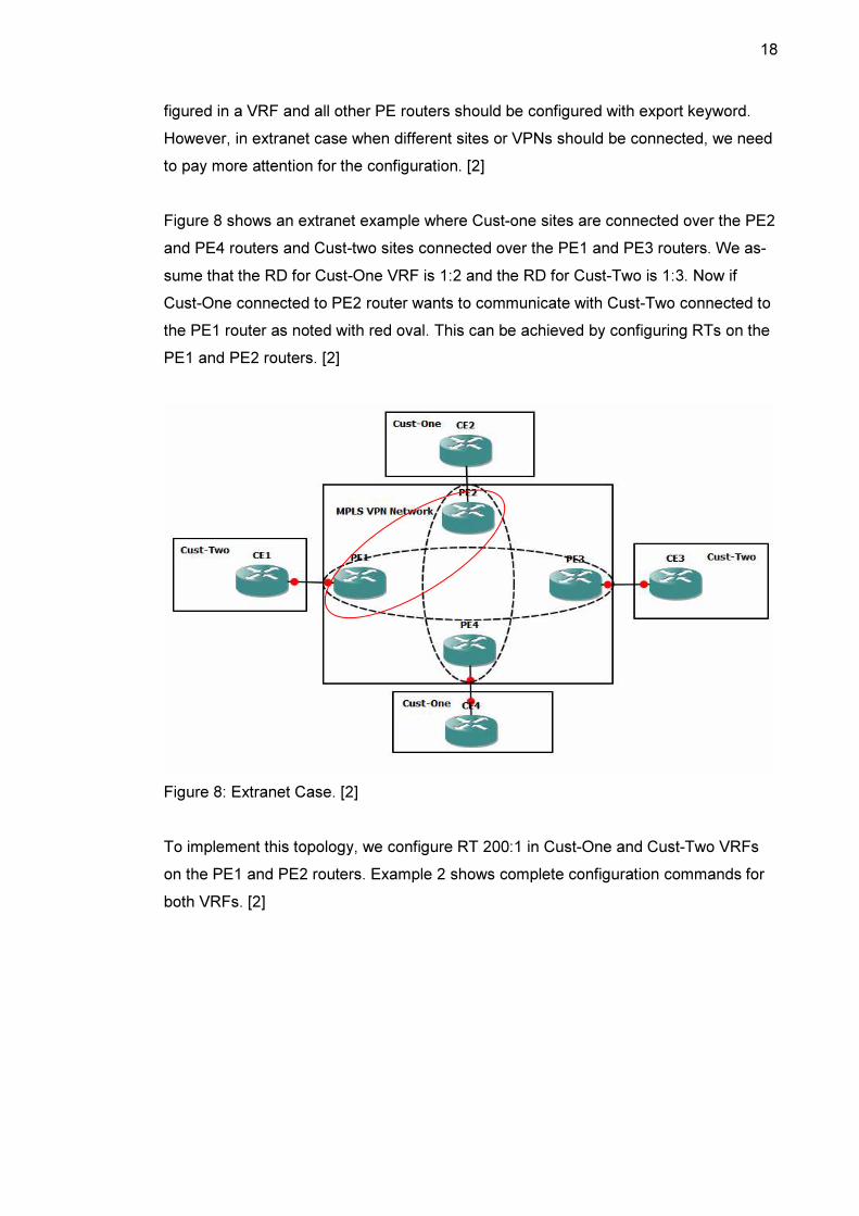
Figure 8 shows an extranet example where Cust-one sites are connected over the PE2
and PE4 routers and Cust-two sites connected over the PE1 and PE3 routers. We as-
sume that the RD for Cust-One VRF is 1:2 and the RD for Cust-Two is 1:3. Now if
Cust-One connected to PE2 router wants to communicate with Cust-Two connected to
the PE1 router as noted with red oval. This can be achieved by configuring RTs on the
PE1 and PE2 routers. [2]
Figure 8: Extranet Case. [2]
To implement this topology, we configure RT 200:1 in Cust-One and Cust-Two VRFs
on the PE1 and PE2 routers. Example 2 shows complete configuration commands for
both VRFs. [2]
19
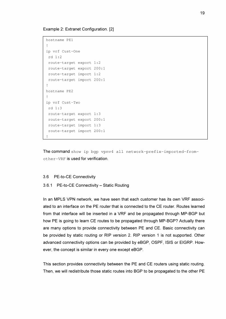
Example 2: Extranet Configuration. [2]
The command show ip bgp vpnv4 all network-prefix-imported-from-
other-VRF is used for verification.
3.6 PE-to-CE Connectivity
3.6.1 PE-to-CE Connectivity – Static Routing
In an MPLS VPN network, we have seen that each customer has its own VRF associ-
ated to an interface on the PE router that is connected to the CE router. Routes learned
from that interface will be inserted in a VRF and be propagated through MP-BGP but
how PE is going to learn CE routes to be propagated through MP-BGP? Actually there
are many options to provide connectivity between PE and CE. Basic connectivity can
be provided by static routing or RIP version 2. RIP version 1 is not supported. Other
advanced connectivity options can be provided by eBGP, OSPF, ISIS or EIGRP. How-
ever, the concept is similar in every one except eBGP.
This section provides connectivity between the PE and CE routers using static routing.
Then, we will redistribute those static routes into BGP to be propagated to the other PE
hostname PE1
!
ip vrf Cust-One
rd 1:2
route-target export 1:2
route-target export 200:1
route-target import 1:2
route-target import 200:1
!
hostname PE2
!
ip vrf Cust-Two
rd 1:3
route-target export 1:3
route-target export 200:1
route-target import 1:3
route-target import 200:1
!

20
routes through MP-iBGP. Static routing option is a good choice when the customer has
only one entry point to the service provider network. [3]
Note that in MPLS VPN, there must be full-mesh BGP sessions between all the PE
routers. We will provide a configuration sample for BGP sessions later in this chapter.
At first, we need to configure each network beyond the CE router on the PE router with
a static route. If we assume that the network prefix of the CE router is 172.16.0.0/24,
the configuration command will be as follows:
PE1(config)# ip route vrf Metropolia 172.16.0.0 255 .255.255.0
serial0 10.10.10.2
Then we need to redistribute this static route into BGP. To do this, we have to use the
redistribute command within address-family sub-mode of the VRF as follows:
router bgp 1
!
address-family ipv4 vrf Metropolia
redistribute connected
redistribute static
exit address-family
!
Using address-family sub-mode makes the router redistribute the routes to only
interfaces associated with the address-family. [3]
Note that the command redistribute connected is added to propagate the net-
work prefix that is directly connected to the PE. Otherwise, the communication of the
VPN sites would fail.
3.6.2 PE-to-CE Connectivity – RIP Version 2
This section provides connectivity between the PE and CE routers using RIP version 2.
The routes learned through RIP form a CE router is placed into the VRF associated to
the interface connected to the CE router. Then, these routes are propagated through
MP-iBGP to other PE routers.
21
As we already know, RIP routing updates consist of all RIP routes in the routing table
plus the RIP-enabled directly connected interfaces. These routing updates are sent out
to all interfaces that belong to the address range of the network command. In an
MPLS VPN network, there is another way to overcome this operation, since it is clearly
not desirable. [3]
Using the address-family sub-mode within the RIP process configuration makes
the router interprets any configuration commands in between as belonging to the speci-
fied VRF. Routes learned through RIP are advertised to only interfaces associated with
the address-family. [3] RIP configuration commands for Aalto VRF as follows:
router rip
!
address-family ipv4 vrf Aalto
version 2
redistribute bgp 1 metric 2
network 10.0.0.0
no auto-summary
exit-address-family
!
This configuration gets the RIP routes propagated through MP-BGP into Aalto VRF.
However, it does not advertise routes leaned through the CE router to other PE routers.
[3] To do this, we should issue the following commands:
router bgp 1
!
address-family ipv4 vrf Aalto
redistribute connected
redistribute rip
exit address-family
!
3.6.3 PE-to-CE Connectivity – eBGP
eBGP can be used as the routing protocol between the PE and CE routers. We just
need to create an eBGP session and activate it under the address family ipv4
22
vrf of the router bgp process on the PE router. [2] A Sample of configuration com-
mands is as follows:
router bgp 1
!
address-family ipv4 vrf Helsinki
redistribute connected
neighbor 10.30.30.6 remote-as 2
neighbor 10.30.30.6 activate
exit-address-family
!
3.7 Interface Association to a VRF
As mentioned earlier in 3.3 section that after defining a VRF, we must associate it with
an interface that is connected to the CE router. This is done by ip vrf forwarding
interface-mode command. Following is a configuration sample:
interface serial0
ip vrf forwarding Aalto
ip address 10.10.10.5 255.255.255.252
When associating an interface to a VRF, the IP address of the interface is removed
from the routing table and also from the interface. Therefore, issuing ip address
command is mandatory after ip vrf forwarding command. [3]
3.8 Route Propagation in an MPLS VPN Network
This section aims to show how customer routes propagate over the MPLS VPN net-
work. The route propagation occurs as follows:
1. Customer IPv4 routes are learnt by the PE router through IGP or eBGP
2. Learnt IPv4 routes are then inserted into a particular VRF routing table asso-
ciated to the CE.
3. IPv4 routes are then redistributed into MP-BGP. A VPNv4 route is made by
adding the RD to the IPv4 route. RTs are also added.
4. MP-iBGP propagates VPNv4 routes with MPLS label and RTs.

23
5. RTs indicate to which VRF the route is imported and RD is removed from the
VPNv4 route.
6. IPv4 routes are inserted into the VRF routing table on the other PE router
7. IGP or eBGP advertises IPv4 routes to the CE at the other site. [2]
3.9 Multiprotocol BGP
3.9.1 Overview of MP-BGP
MP-BGP will be introduced in this section since it is the only routing protocol used to
propagate customer routes between the PE routers.
BGP is a standard protocol used for interdomain routing that makes up the internet.
Service providers run BGP between them as the routing protocol. BGP is a powerful
protocol that has the capability to carry out thousands of IPv4 or IPv6 routes and allows
polices to be implemented. A service provider peers with other service provider through
eBGP and runs iBGP internally.
Multiprotocol extension of BGP (RFC 2858) was developed to carry other routing in-
formation than IPv4. When IPv6 was developed, Multiprotocol BGP has the capability
to carry IPv6 prefixes. This feature of Multiprotocol BGP allows us to carry the label to
identify the MPLS VPN (or Virtual Routing and Forwarding table VRF). Basically MP-
BGP has the capability to carry any routing protocol information.
3.9.2 Multiprotocol BGP Configuration
The first step of MP-BGP configuration is to create BGP sessions between the PE
routers in the MPLS VPN network. A full-mesh topology of BGP sessions must be cre-
ated for all the PE routers. Sample configuration commands as follows:
router bgp 1
neighbor 192.168.0.205 remote as 1
neighbor 192.168.0.205 update-source loopback0
neighbor 192.168.0.205 activate
!
24
Note that the IP address of the loopback0 interface was used to peer the PE routers.
This configuration is recommended especially in the service provider network.
The other configuration step is to activate the MP-iBGP session in order to exchange
VPN-IPv4 prefixes using address-family sub-mode in the BGP process configuration.
This configuration must be applied for each VRF configured in the PE router. The us-
age of address-family allows MP-BGP to carry protocols other than IPv4. The configu-
ration commands as follows:
router bgp 1
!
address-family vpnv4
neighbor 192.168.0.205 activate
neighbor 192.168.0.205 send-community extended
exit address-family
When issuing the command neighbor 192.168.0.205 activate , there is no
need to issue the command neighbor 192.168.0.205 send community ex-
tended because it is added by default. [3]
RD and RTs are called extended community attributes that have been added to the
standard BGP to create MP-BGP. In order to MP-BGP to propagate these extended
community attributes, the command neighbor 192.168.0.205 send community
extended must be added as shown above.
3.10 MPLS VPN Site Expansion
Imagine a VPN customer who has two sites interconnected over a service provider
network is requesting a connectivity for a third site, how this site is connected over the
service provider network? In an MPLS VPN network, connecting third site is like plug
and play. The customer VPN needs to be added on the PE router associated to the
third site CE with same configuration of VRF, RD and RTs. In addition, we need to acti-
vate MP-BGP in order to propagate VPNv4 routes over the PE routers connected to
customer sites. If the third customer site is added to the same PE router which is con-
nected to the first or second customer site, the third site router interface needs only to
be associated to the customer VRF.

25
3.11 MPLS VPN Example
Figure 9 shows an MPLS VPN network which consists of 4 P routers in the core, 4 PE
routers and 3 customers (Metropolia, Aalto and Helsinki). The objective of the MPLS
VPN network is to connect customer sites with each other (Metropolia customer has
two sites, Aalto has 3 sites and Helsinki has 2 sites). For PE-to-CE connectivity, we will
implement static routing for Metropolia, RIP for Aalto and eBGP for Helsinki.
Let us assume that one of the requirements of the customers Metropolia and Helsinki is
to make an extranet between them on the PE2 and PE3 routers.
In this MPLS VPN example, we are going to present the configuration commands of
the MPLS VPN network to create connectivity between customer sites, network infra-
structure and MPLS configuration commands will also be shown. Full configuration
commands are listed in Appendix 1.
Figure 9: MPLS VPN Sample
There are certain commands that allow us to access and troubleshoot VRF tables
within the MPLS VPN network. These commands are ping, traceroute, telnet and show
ip route as follows:

26
PE1# ping vrf Metropolia 172.16.0.1
PE1# telnet 172.16.1.1 /vrf Helsinki
PE1# traceroute vrf Aalto 172.16.2.1
PE1# show ip route vrf Metropolia
In the MPLS VPN configuration sample, we will notice that every site has a route to
every destination network on the other site(s). This is not always desirable due to the
fact that an organization contains HQ and braches. Braches should not have all net-
work routes to the HQ. There is a way that we could control the routes advertised
through MP-BGP using route map. This solution will not be discussed in here.
3.12 Testing an MPLS VPN Network
The command show ip route vrf VPN-name determines the starting point of testing
for a customer VPN in case remote routes are propagated from other site(s) through
MP-BGP. Otherwise, we should troubleshoot the customer VPN.
In the MPLS VPN example implemented in Appendix 1, let us test Aalto VPN (every
VPN is completely independent). Recall that Aalto VPN consists of 3 sites (on PE1,
PE2 and PE3 routers) and it uses RIP as the routing protocol for PE-to-CE connec-
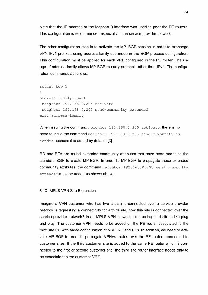
tivity. In the beginning, we have to show the sample configuration of all CE routers of
Aalto VPN (As a service provider, access to CE routers is not possible). Example 3
shows a sample configuration of all Aalto CE routers.
27
hostname CE2
!
interface Loopback0
ip address 172.16.0.1
255.255.255.0
!
interface
FastEthernet0/0
ip address 10.10.10.6
255.255.255.252
!
router rip
version 2
network 10.0.0.0
network 172.16.0.0
no auto-summary
!
hostname CE4
!
interface Loopback0
ip address 172.16.2.1
255.255.255.0
!
interface
FastEthernet0/0
ip address 10.30.30.2
255.255.255.252
!
router rip
version 2
network 10.0.0.0
network 172.16.0.0
no auto-summary
!
hostname CE6
!
interface Loopback0
ip address 172.16.1.1
255.255.255.0
!
interface
FastEthernet0/0
ip address 10.20.20.6
255.255.255.252
!
router rip
version 2
network 10.0.0.0
network 172.16.0.0
no auto-summary
!
Example 3: Sample Configuration of Aalto CE routers
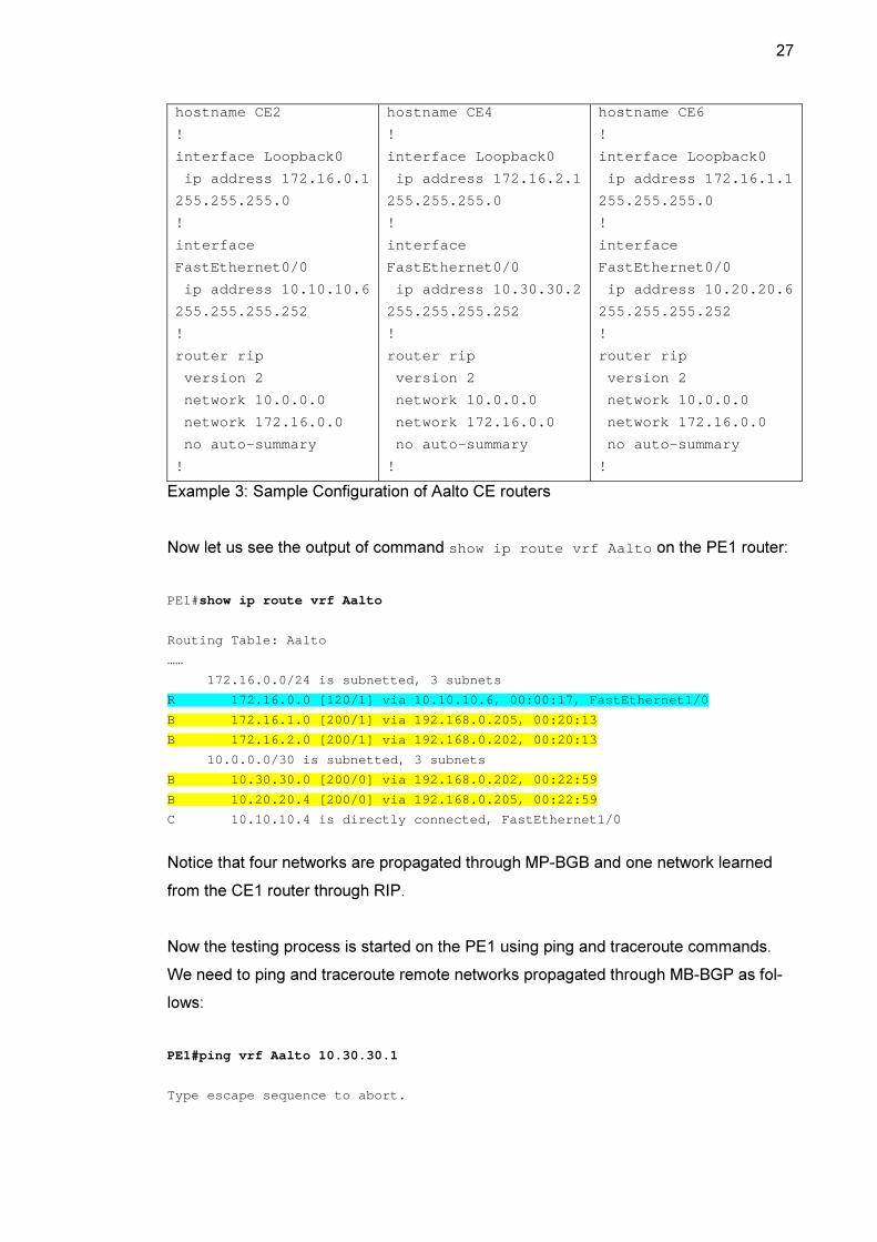
Now let us see the output of command show ip route vrf Aalto on the PE1 router:
PE1#show ip route vrf Aalto
Routing Table: Aalto
……
172.16.0.0/24 is subnetted, 3 subnets
R 172.16.0.0 [120/1] via 10.10.10.6, 00:00:17 , FastEthernet1/0
B 172.16.1.0 [200/1] via 192.168.0.205, 00:20 :13
B 172.16.2.0 [200/1] via 192.168.0.202, 00:20 :13
10.0.0.0/30 is subnetted, 3 subnets
B 10.30.30.0 [200/0] via 192.168.0.202, 00:22 :59
B 10.20.20.4 [200/0] via 192.168.0.205, 00:22 :59
C 10.10.10.4 is directly connected, FastEther net1/0
Notice that four networks are propagated through MP-BGB and one network learned
from the CE1 router through RIP.
Now the testing process is started on the PE1 using ping and traceroute commands.
We need to ping and traceroute remote networks propagated through MB-BGP as fol-
lows:
PE1#ping vrf Aalto 10.30.30.1
Type escape sequence to abort.

28
Sending 5, 100-byte ICMP Echos to 10.30.30.1, timeo ut is 2 seconds:
!!!!!
Success rate is 100 percent (5/5), round-trip min/a vg/max = 144/215/308 ms
PE1#ping vrf Aalto 10.20.20.5
Type escape sequence to abort.
Sending 5, 100-byte ICMP Echos to 10.20.20.5, timeo ut is 2 seconds:
!!!!!
Success rate is 100 percent (5/5), round-trip min/a vg/max = 248/343/424 ms
PE1#ping vrf Aalto 172.16.1.1
Type escape sequence to abort.
Sending 5, 100-byte ICMP Echos to 172.16.1.1, timeo ut is 2 seconds:
!!!!!
Success rate is 100 percent (5/5), round-trip min/a vg/max = 296/348/432 ms
PE1#ping vrf Aalto 172.16.2.1
Type escape sequence to abort.
Sending 5, 100-byte ICMP Echos to 172.16.2.1, timeo ut is 2 seconds:
!!!!!
Success rate is 100 percent (5/5), round-trip min/a vg/max = 248/296/356 ms
PE1#traceroute vrf Aalto 172.16.1.1
Type escape sequence to abort.
Tracing the route to 172.16.1.1
1 192.168.0.17 [MPLS: Labels 23/28 Exp 0] 40 msec 64 msec 32 msec
2 192.168.0.2 [MPLS: Labels 23/28 Exp 0] 48 msec 36 msec 32 msec
3 192.168.0.6 [MPLS: Labels 23/28 Exp 0] 44 msec 28 msec 36 msec
4 10.20.20.5 [MPLS: Label 28 Exp 0] 36 msec 24 ms ec 28 msec
5 10.20.20.6 28 msec * 48 msec
PE1#traceroute vrf Aalto 172.16.2.1
Type escape sequence to abort.
Tracing the route to 172.16.2.1
1 192.168.0.17 [MPLS: Labels 18/26 Exp 0] 40 msec 52 msec 44 msec
2 192.168.0.2 [MPLS: Labels 16/26 Exp 0] 44 msec 40 msec 68 msec
3 10.30.30.1 [MPLS: Label 26 Exp 0] 32 msec 32 ms ec 16 msec
4 10.30.30.2 36 msec * 56 msec
Then we should continue testing other PE routers using ping and traceroute commands
as shown above. The Aalto customer can also test his own sites using the normal ping
and traceroute commands.
29
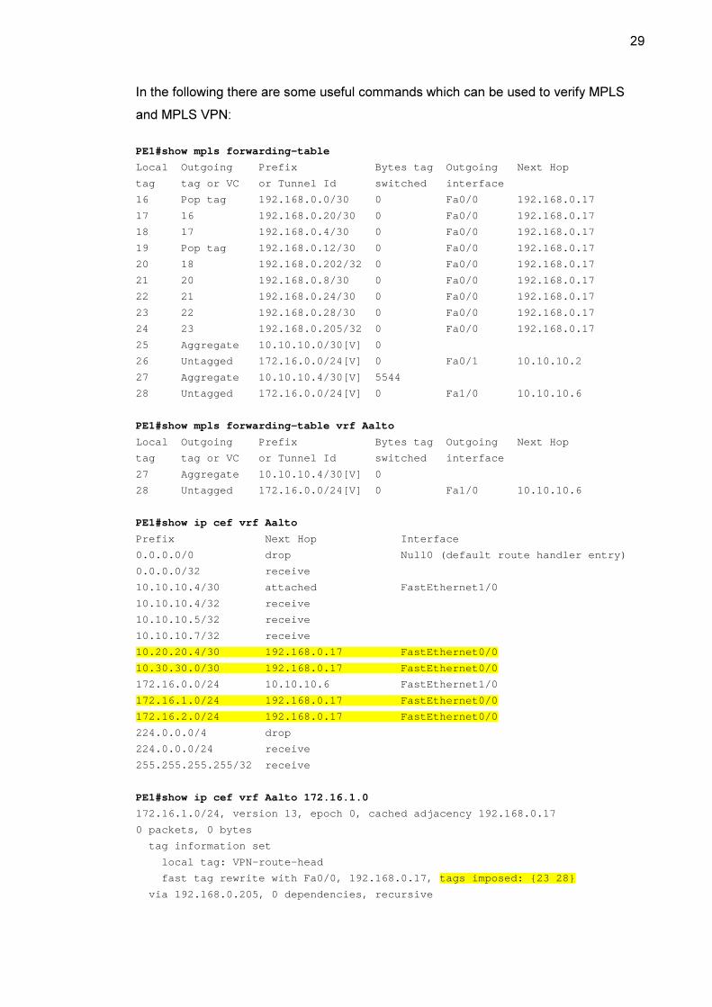
In the following there are some useful commands which can be used to verify MPLS
and MPLS VPN:
PE1#show mpls forwarding-table
Local Outgoing Prefix Bytes tag Out going Next Hop
tag tag or VC or Tunnel Id switched int erface
16 Pop tag 192.168.0.0/30 0 Fa0 /0 192.168.0.17
17 16 192.168.0.20/30 0 Fa0 /0 192.168.0.17
18 17 192.168.0.4/30 0 Fa0 /0 192.168.0.17
19 Pop tag 192.168.0.12/30 0 Fa0 /0 192.168.0.17
20 18 192.168.0.202/32 0 Fa0 /0 192.168.0.17
21 20 192.168.0.8/30 0 Fa0 /0 192.168.0.17
22 21 192.168.0.24/30 0 Fa0 /0 192.168.0.17
23 22 192.168.0.28/30 0 Fa0 /0 192.168.0.17
24 23 192.168.0.205/32 0 Fa0 /0 192.168.0.17
25 Aggregate 10.10.10.0/30[V] 0
26 Untagged 172.16.0.0/24[V] 0 Fa0 /1 10.10.10.2
27 Aggregate 10.10.10.4/30[V] 5544
28 Untagged 172.16.0.0/24[V] 0 Fa1 /0 10.10.10.6
PE1#show mpls forwarding-table vrf Aalto
Local Outgoing Prefix Bytes tag Out going Next Hop
tag tag or VC or Tunnel Id switched int erface
27 Aggregate 10.10.10.4/30[V] 0
28 Untagged 172.16.0.0/24[V] 0 Fa1 /0 10.10.10.6
PE1#show ip cef vrf Aalto
Prefix Next Hop Interface
0.0.0.0/0 drop Null0 (def ault route handler entry)
0.0.0.0/32 receive
10.10.10.4/30 attached FastEthern et1/0
10.10.10.4/32 receive
10.10.10.5/32 receive
10.10.10.7/32 receive
10.20.20.4/30 192.168.0.17 FastEthern et0/0
10.30.30.0/30 192.168.0.17 FastEthern et0/0
172.16.0.0/24 10.10.10.6 FastEthern et1/0
172.16.1.0/24 192.168.0.17 FastEthern et0/0
172.16.2.0/24 192.168.0.17 FastEthern et0/0
224.0.0.0/4 drop
224.0.0.0/24 receive
255.255.255.255/32 receive
PE1#show ip cef vrf Aalto 172.16.1.0
172.16.1.0/24, version 13, epoch 0, cached adjacenc y 192.168.0.17
0 packets, 0 bytes
tag information set
local tag: VPN-route-head
fast tag rewrite with Fa0/0, 192.168.0.17, tags imposed: {23 28}
via 192.168.0.205, 0 dependencies, recursive

30
next hop 192.168.0.17, FastEthernet0/0 via 192. 168.0.205/32
valid cached adjacency
tag rewrite with Fa0/0, 192.168.0.17, tags impo sed: {23 28
PE1#show mpls ldp neighbor
Peer LDP Ident: 192.168.0.17:0; Local LDP Ident 192.168.0.201:0
TCP connection: 192.168.0.17.646 - 192.168.0.201.5 7001
State: Oper; Msgs sent/rcvd: 29/28; Downstream
Up time: 00:12:47
LDP discovery sources:
FastEthernet0/0, Src IP addr: 192.168.0.17
Addresses bound to peer LDP Ident:
192.168.0.1 192.168.0.14 192.168.0 .17
PE1#show mpls ldp discovery
Local LDP Identifier:
192.168.0.201:0
Discovery Sources:
Interfaces:
FastEthernet0/0 (ldp): xmit/recv
LDP Id: 192.168.0.17:0; no host route
PE1#show ip bgp vpnv4 rd 1:3
BGP table version is 23, local router ID is 192.168 .0.201
Status codes: s suppressed, d damped, h history, * valid, > best, i - inter-
nal,
r RIB-failure, S Stale
Origin codes: i - IGP, e - EGP, ? - incomplete
Network Next Hop Metric LocP rf Weight Path
Route Distinguisher: 1:3 (default for vrf Aalto)
*> 10.10.10.4/30 0.0.0.0 0 32768 ?
*>i10.20.20.4/30 192.168.0.205 0 1 00 0 ?
*>i10.30.30.0/30 192.168.0.202 0 1 00 0 ?
*> 172.16.0.0/24 10.10.10.6 1 32768 ?
*>i172.16.1.0/24 192.168.0.205 1 1 00 0 ?
*>i172.16.2.0/24 192.168.0.202 1 1 00 0 ?
All these verification commands have been issued on the PE1 router only. Verifying
other PE routers (PE2 and PE3) should be continued.
3.13 Advanced MPLS VPN Topologies
3.13.1 Intranet and Extranet Example
Intranet and extranet topologies were briefly discussed earlier in section 3.5. The idea
of implementing these topologies is to configure route target BGP extended community
31
attributes to export and import routes within a site or various sites. Depending on how
these attributes are configured, it clearly identifies the implemented topology. In this
section, we will discuss only two topologies:
1. Intranet and Extranet Topologies
2. Central Services Topology
Intranet and extranet are the most common topologies implemented in the service pro-
vider network. The statements of route targets BGP extended community attributes
control the behaviour of the VRF communications. [3]
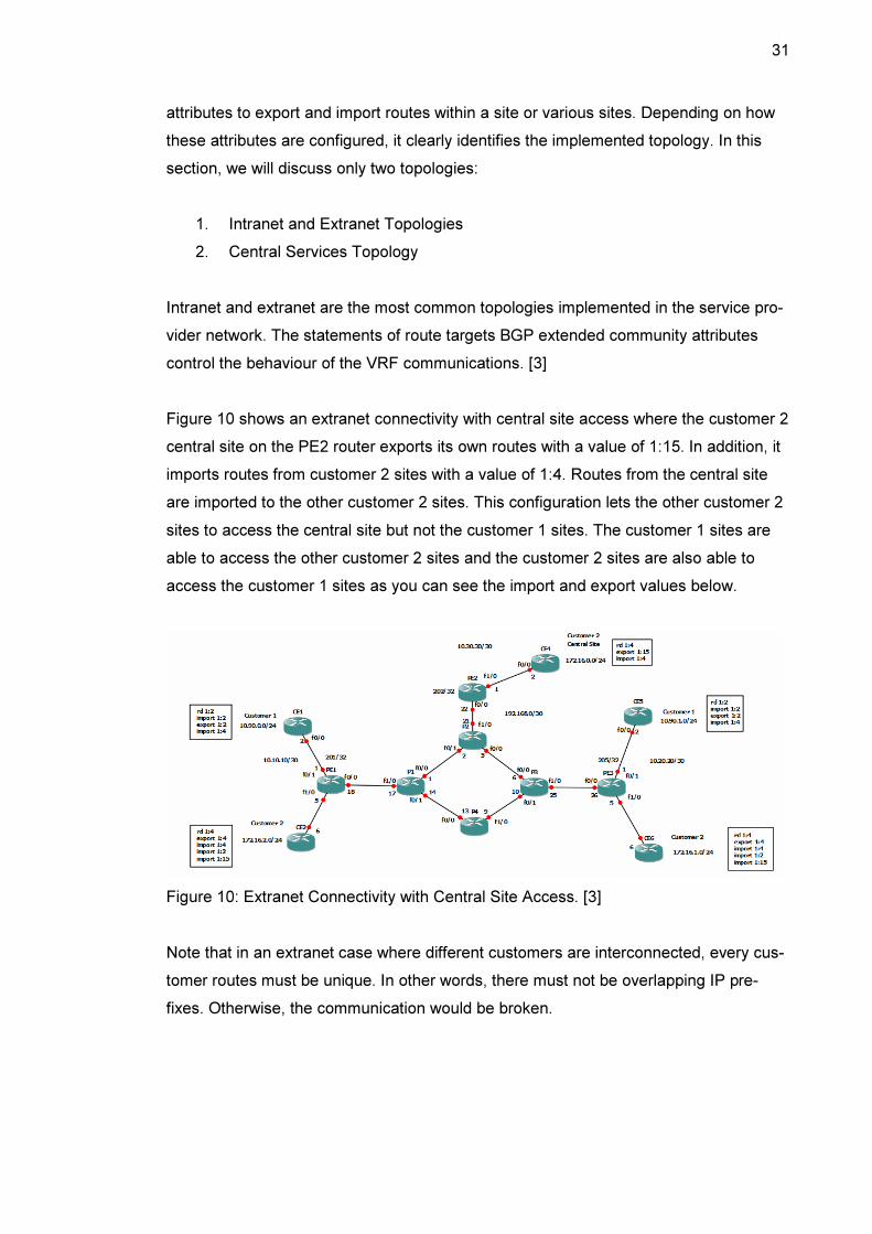
Figure 10 shows an extranet connectivity with central site access where the customer 2
central site on the PE2 router exports its own routes with a value of 1:15. In addition, it
imports routes from customer 2 sites with a value of 1:4. Routes from the central site
are imported to the other customer 2 sites. This configuration lets the other customer 2
sites to access the central site but not the customer 1 sites. The customer 1 sites are
able to access the other customer 2 sites and the customer 2 sites are also able to
access the customer 1 sites as you can see the import and export values below.
Figure 10: Extranet Connectivity with Central Site Access. [3]
Note that in an extranet case where different customers are interconnected, every cus-
tomer routes must be unique. In other words, there must not be overlapping IP pre-
fixes. Otherwise, the communication would be broken.

32
3.13.2 Central Services Topology
Organizations provide services to clients on central servers located on one or more
central sites such as application hosting or access to shared resources. Client sites
must not be able to communicate with each other. This is one of the requirements of
implementing Central Services Topology. [3]
To implement this topology, we need to do the following:
1. Create a separate VRF for each client site so that clients can not communi-
cate with each other
2. Configure each VRF with a different RD. [3]
Server sites must be able to communicate with each other. They should be configured
with the same VRF if connected to the same PE. Otherwise, we can use the same RD.
Concerning RTs, we need to do the following:
1. Server routes should be exported to clients with a route target such as
Server_RT
2. Clients should import server routes into their own VRFs
3. Clients routes should be exported with a common route target such as Cli-
ent_RT
4. Severs should import clients routes into their own VRFs
5. Client routes should not be imported to other clients. [3]
Using the same MPLS VPN network implemented in the previous chapter, we assume
that Metropolia customer requires deploying a server (called MetroServer) on the PE4
router and it serves Metropolia and Helsinki clients as shown in figure 11 below. Hel-
sinki clients should not be able to communicate with Metropolia clients.

33
Figure 11: Central Services Topology
At first, we should create and configure MetroServer VRF as follows:
ip vrf MetroServer
rd 1:10
route-target both 1:20 ! Server_RT
route-target import 1:40 ! Client_RT
!
On the client side (Metropolia and Helsinki), we should import the server route target
and export their own route targets as shown below:
ip vrf Metropolia
rd 1:2
route-target import 1:20 ! Server_RT
route-target export 1:40 ! Client_RT
!
ip vrf Helsinki
rd 1:4
route-target import 1:20 ! Server_RT
route-target export 1:40 ! Client_RT
!
34
Then we have to configure the interface associated to MetroServer on the PE4 router,
routing protocol and redistribution of routes from MetroServer VRF into MP-BGP. Full
configuration commands are listed in Appendix 2.
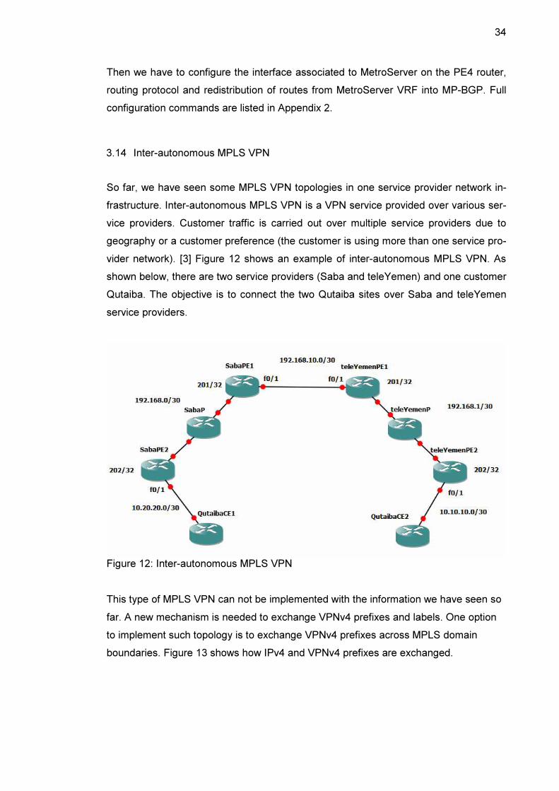
3.14 Inter-autonomous MPLS VPN
So far, we have seen some MPLS VPN topologies in one service provider network in-
frastructure. Inter-autonomous MPLS VPN is a VPN service provided over various ser-
vice providers. Customer traffic is carried out over multiple service providers due to
geography or a customer preference (the customer is using more than one service pro-
vider network). [3] Figure 12 shows an example of inter-autonomous MPLS VPN. As
shown below, there are two service providers (Saba and teleYemen) and one customer
Qutaiba. The objective is to connect the two Qutaiba sites over Saba and teleYemen
service providers.
Figure 12: Inter-autonomous MPLS VPN
This type of MPLS VPN can not be implemented with the information we have seen so
far. A new mechanism is needed to exchange VPNv4 prefixes and labels. One option
to implement such topology is to exchange VPNv4 prefixes across MPLS domain
boundaries. Figure 13 shows how IPv4 and VPNv4 prefixes are exchanged.
35
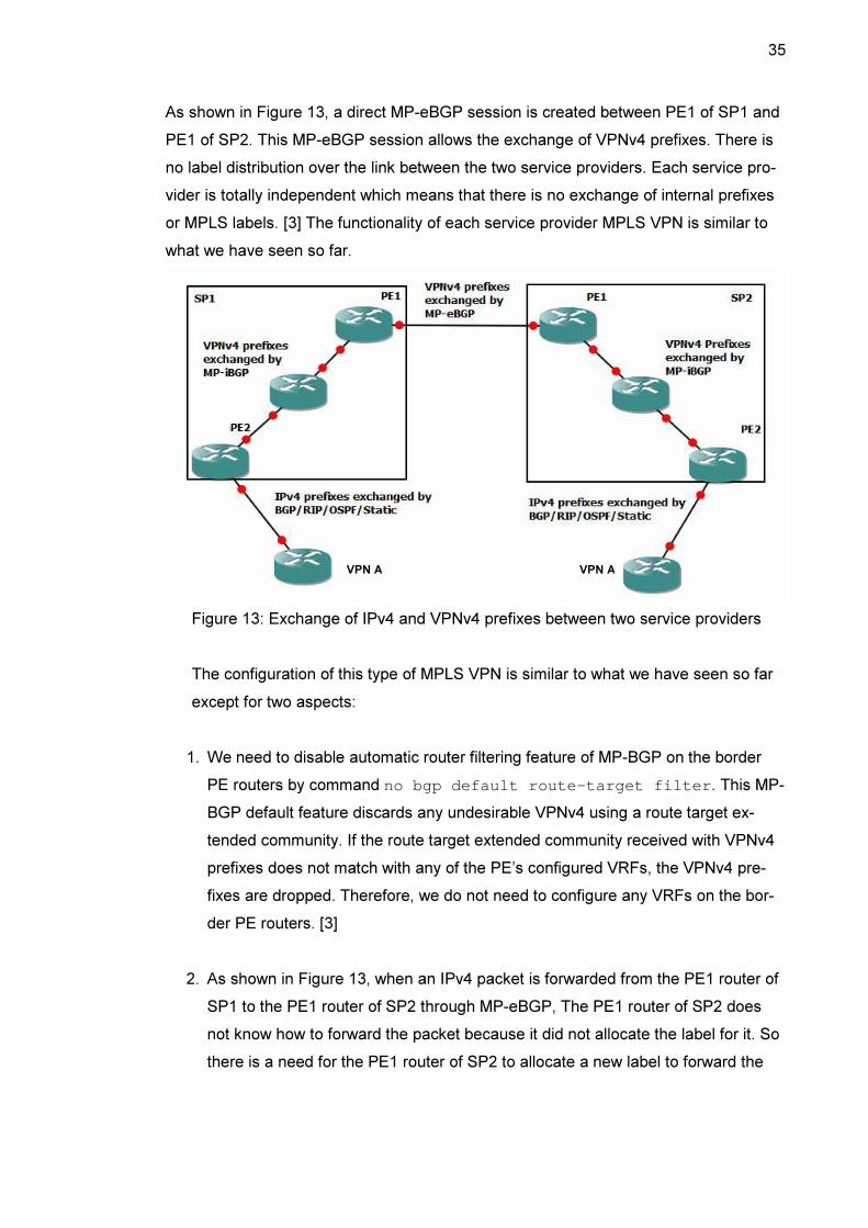
As shown in Figure 13, a direct MP-eBGP session is created between PE1 of SP1 and
PE1 of SP2. This MP-eBGP session allows the exchange of VPNv4 prefixes. There is
no label distribution over the link between the two service providers. Each service pro-
vider is totally independent which means that there is no exchange of internal prefixes
or MPLS labels. [3] The functionality of each service provider MPLS VPN is similar to
what we have seen so far.
Figure 13: Exchange of IPv4 and VPNv4 prefixes between two service providers
The configuration of this type of MPLS VPN is similar to what we have seen so far
except for two aspects:
1. We need to disable automatic router filtering feature of MP-BGP on the border
PE routers by command no bgp default route-target filter . This MP-
BGP default feature discards any undesirable VPNv4 using a route target ex-
tended community. If the route target extended community received with VPNv4
prefixes does not match with any of the PE’s configured VRFs, the VPNv4 pre-
fixes are dropped. Therefore, we do not need to configure any VRFs on the bor-
der PE routers. [3]
2. As shown in Figure 13, when an IPv4 packet is forwarded from the PE1 router of
SP1 to the PE1 router of SP2 through MP-eBGP, The PE1 router of SP2 does
not know how to forward the packet because it did not allocate the label for it. So
there is a need for the PE1 router of SP2 to allocate a new label to forward the
VPN A VPN A
36
packet. This is achieved by next-hop-self command. [3] Full configuration
commands of Figure 12 are listed in Appendix 3.
4 Introduction to AToM and VPLS
4.1 Any Transport over MPLS
4.1.1 Overview of AToM
Any Transport over MPLS represents L2 MPLS VPN or L2VPN in Cisco and provides a
L2 point-to-point VPN service. This technology was introduced years later after the
deployment of MPLS VPN in order to carry the L2 traffic between customer sites since
MPLS VPN has no support for L2 protocols. There are many L2 protocols supported by
AToM such as Ethernet, HLDC, PPP, ATM or Frame Relay. [2]
Before the deployment of AToM, other network infrastructure was carrying L2 traffic
besides the MPLS network. So there were two network infrastructures. AToM was inte-
grated to the MPLS network so that L2 or L3 traffic is transported over the same MPLS
network infrastructure. [2] AToM works in a similar way as MPLS VPN where popping
and pushing the label are made in the PE routers and the P routers are not aware of
the existence of VPNs; they just forward packets by swapping the outer label. However,
the label stack location depends on the L2 protocol used. PHP is also applied.
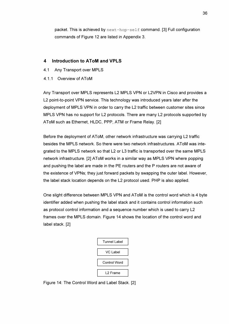
One slight difference between MPLS VPN and AToM is the control word which is 4 byte
identifier added when pushing the label stack and it contains control information such
as protocol control information and a sequence number which is used to carry L2
frames over the MPLS domain. Figure 14 shows the location of the control word and
label stack. [2]
Figure 14: The Control Word and Label Stack. [2]
Tunnel Label
VC Label
Control Word
L2 Frame
37
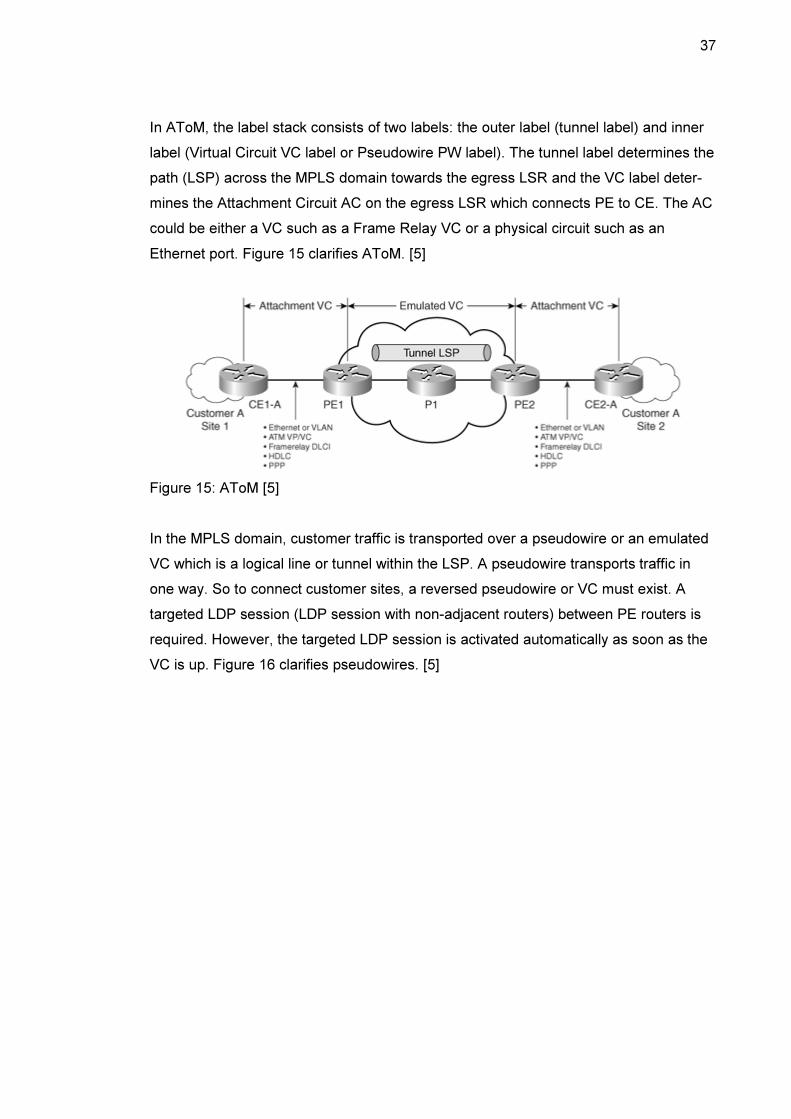
In AToM, the label stack consists of two labels: the outer label (tunnel label) and inner
label (Virtual Circuit VC label or Pseudowire PW label). The tunnel label determines the
path (LSP) across the MPLS domain towards the egress LSR and the VC label deter-
mines the Attachment Circuit AC on the egress LSR which connects PE to CE. The AC
could be either a VC such as a Frame Relay VC or a physical circuit such as an
Ethernet port. Figure 15 clarifies AToM. [5]
Figure 15: AToM [5]
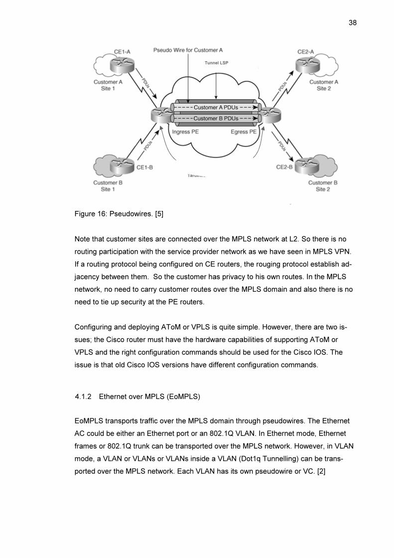
In the MPLS domain, customer traffic is transported over a pseudowire or an emulated
VC which is a logical line or tunnel within the LSP. A pseudowire transports traffic in
one way. So to connect customer sites, a reversed pseudowire or VC must exist. A
targeted LDP session (LDP session with non-adjacent routers) between PE routers is
required. However, the targeted LDP session is activated automatically as soon as the
VC is up. Figure 16 clarifies pseudowires. [5]
38
Figure 16: Pseudowires. [5]
Note that customer sites are connected over the MPLS network at L2. So there is no
routing participation with the service provider network as we have seen in MPLS VPN.
If a routing protocol being configured on CE routers, the rouging protocol establish ad-
jacency between them. So the customer has privacy to his own routes. In the MPLS
network, no need to carry customer routes over the MPLS domain and also there is no
need to tie up security at the PE routers.
Configuring and deploying AToM or VPLS is quite simple. However, there are two is-
sues; the Cisco router must have the hardware capabilities of supporting AToM or
VPLS and the right configuration commands should be used for the Cisco IOS. The
issue is that old Cisco IOS versions have different configuration commands.
4.1.2 Ethernet over MPLS (EoMPLS)
EoMPLS transports traffic over the MPLS domain through pseudowires. The Ethernet
AC could be either an Ethernet port or an 802.1Q VLAN. In Ethernet mode, Ethernet
frames or 802.1Q trunk can be transported over the MPLS network. However, in VLAN
mode, a VLAN or VLANs or VLANs inside a VLAN (Dot1q Tunnelling) can be trans-
ported over the MPLS network. Each VLAN has its own pseudowire or VC. [2]
Targeted LDP session
Tunnel LSP
39
4.2 VPLS
Virtual Private LAN Service (VPLS) is a L2 point-to-multipoint VPN service where the
MPLS network emulates a virtual Ethernet switch which has the same characteristics
as the Ethernet switch. Even though VPLS provides a point-to-multipoint VPN service,
it works in similar way as L2 point-to-point VPN service. VPLS creates a full-mesh to-
pology of pseudowires for each customer site. The label stack also consists of two la-
bels, the tunnel label and VC or PW label. [2]
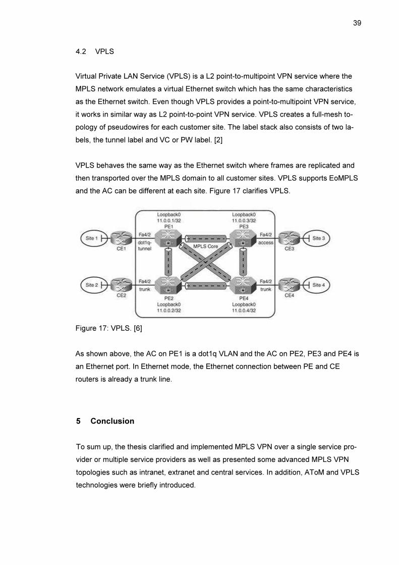
VPLS behaves the same way as the Ethernet switch where frames are replicated and
then transported over the MPLS domain to all customer sites. VPLS supports EoMPLS
and the AC can be different at each site. Figure 17 clarifies VPLS.
Figure 17: VPLS. [6]
As shown above, the AC on PE1 is a dot1q VLAN and the AC on PE2, PE3 and PE4 is
an Ethernet port. In Ethernet mode, the Ethernet connection between PE and CE
routers is already a trunk line.
5 Conclusion
To sum up, the thesis clarified and implemented MPLS VPN over a single service pro-
vider or multiple service providers as well as presented some advanced MPLS VPN
topologies such as intranet, extranet and central services. In addition, AToM and VPLS
technologies were briefly introduced.
40
MPLS is a powerful forwarding technology used to resolve the scalability issue as a
result of separating the control and data planes as well as to reduce the lookup process
overheard in the service provider network. In the core of the MPLS network, IPv4
packets get forwarded based on labels (a 4-byte identifier) which correspond to the
destination networks.
MPLS VPN is the platform of all services provided in the service provider network. It
takes the best features of overlay VPNs and the Peer-to-Peer VPNs. Every customer
or service is represented as an MPLS VPN, and it contains a Virtual and Forwarding
table (VRF) which is used in a similar way as the global routing table but for that spe-
cific VPN. RD makes the VPN routes unique and RTs control the communication be-
tween customer sites. MB-BGP propagates VPNv4 routes between the PE routers or
between service providers (inter-autonomous MPLS VPN).
There are many options for PE-to-CE connectivity, static routes, RIP, eBGP, OSPF,
ISIS and EIGRP. Static routes are a good choice when there is a single entry point to
the service provider network. The usage of PE-to-CE connectivity routing protocol de-
pends on the routing protocol used by the customer.
Intranet is created when connecting several sites to a central site but for the same
MPLS VPN and extranet is created when various sites are connected to each other.
Intranet and extranet topologies can be integrated with each other. In addition, a server
can be deployed within the service provider network to provide services to a customer,
several customers or it can be connected to the Internet. Inter-autonomous MPLS VPN
is a VPN service over multiple service providers. Service providers exchange VPNv4
routes using MP-eBGP.
AToM is an L2 point-to-point VPN service which connects customer sites at L2 through
pseudowires. The AC at each site could be different, Ehternet port, 802.1Q VLAN, PPP
connection or HDLC link. VPLS is an L2 point-to-multipoint VPN service which emu-
lates a virtual Ethernet switch.
41
References
1. Student Guide, Implementing Cisco MPLS, Cisco Systems, Inc., 2006, Volume
1, Version 2.2: Cisco Press.
2. MPLS Fundamentals, Lue De Ghein, 2007: Cisco Press.
3. MPLS and VPN Architectures, CCIP Edition, Ivan Pepelnjak, Jim Guichard,
2002: Cisco Press.
4. MPLS Fundamentals: Forwarding Labeled Packets [online]
URL: http://www.ciscopress.com/articles/article.asp?p=680824.
Access date 30 March 2013
5. Introduction to Layer 2 VPNS [online]
URL: http://mpls-configuration-on-cisco-ios-
software.org.ua/1587051990/ch11lev1sec1.html.
Access date 19 April 2013
6. MPLS: The Core [online]
URL: http://chetanress.blogspot.fi/2010/07/vpls-implementation.html.
Access date 20 April 2013

Appendix
1 (19)
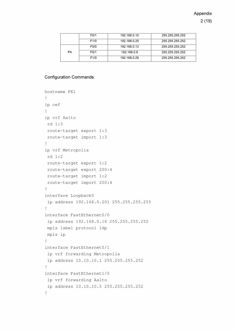
Appendix 1: MPLS VPN Example
The MPLS VPN network topology to be implemented:
Router Interface IP Address Subnet Mask
F0/0 192.168.0.18 255.255.255.252
F0/1 10.10.10.1 255.255.255.252
F1/0 10.10.10.5 255.255.255.252 PE1
Loopback0 192.168.0.201 255.255.255.255
F0/0 192.168.0.22 255.255.255.252
F0/1 10.30.30.5 255.255.255.252
F1/0 10.30.30.1 255.255.255.252 PE2
Loopback0 192.168.0.202 255.255.255.255
F0/0 192.168.0.26 255.255.255.252
F0/1 10.20.20.1 255.255.255.252
F1/0 10.20.20.5 255.255.255.252 PE3
Loopback0 192.168.0.205 255.255.255.255
F0/0 192.168.0.30 255.255.255.252
F0/1 10.40.40.1 255.255.255.252 PE4
Loopback0 192.168.0.206 255.255.255.255
F0/0 192.168.0.1 255.255.255.252
F0/1 192.168.0.14 255.255.255.252 P1
F1/0 192.168.0.17 255.255.255.252
F0/0 192.168.0.5 255.255.255.252
F0/1 192.168.0.2 255.255.255.252 P2
F1/0 192.168.0.21 255.255.255.252
P3 F0/0 192.168.0.6 255.255.255.252
Appendix
2 (19)
F0/1 192.168.0.10 255.255.255.252
F1/0 192.168.0.25 255.255.255.252
F0/0 192.168.0.13 255.255.255.252
F0/1 192.168.0.9 255.255.255.252 P4
F1/0 192.168.0.29 255.255.255.252
Configuration Commands:
hostname PE1
!
ip cef
!
ip vrf Aalto
rd 1:3
route-target export 1:3
route-target import 1:3
!
ip vrf Metropolia
rd 1:2
route-target export 1:2
route-target export 200:4
route-target import 1:2
route-target import 200:4
!
interface Loopback0
ip address 192.168.0.201 255.255.255.255
!
interface FastEthernet0/0
ip address 192.168.0.18 255.255.255.252
mpls label protocol ldp
mpls ip
!
interface FastEthernet0/1
ip vrf forwarding Metropolia
ip address 10.10.10.1 255.255.255.252
!
interface FastEthernet1/0
ip vrf forwarding Aalto
ip address 10.10.10.5 255.255.255.252
!
Appendix
3 (19)
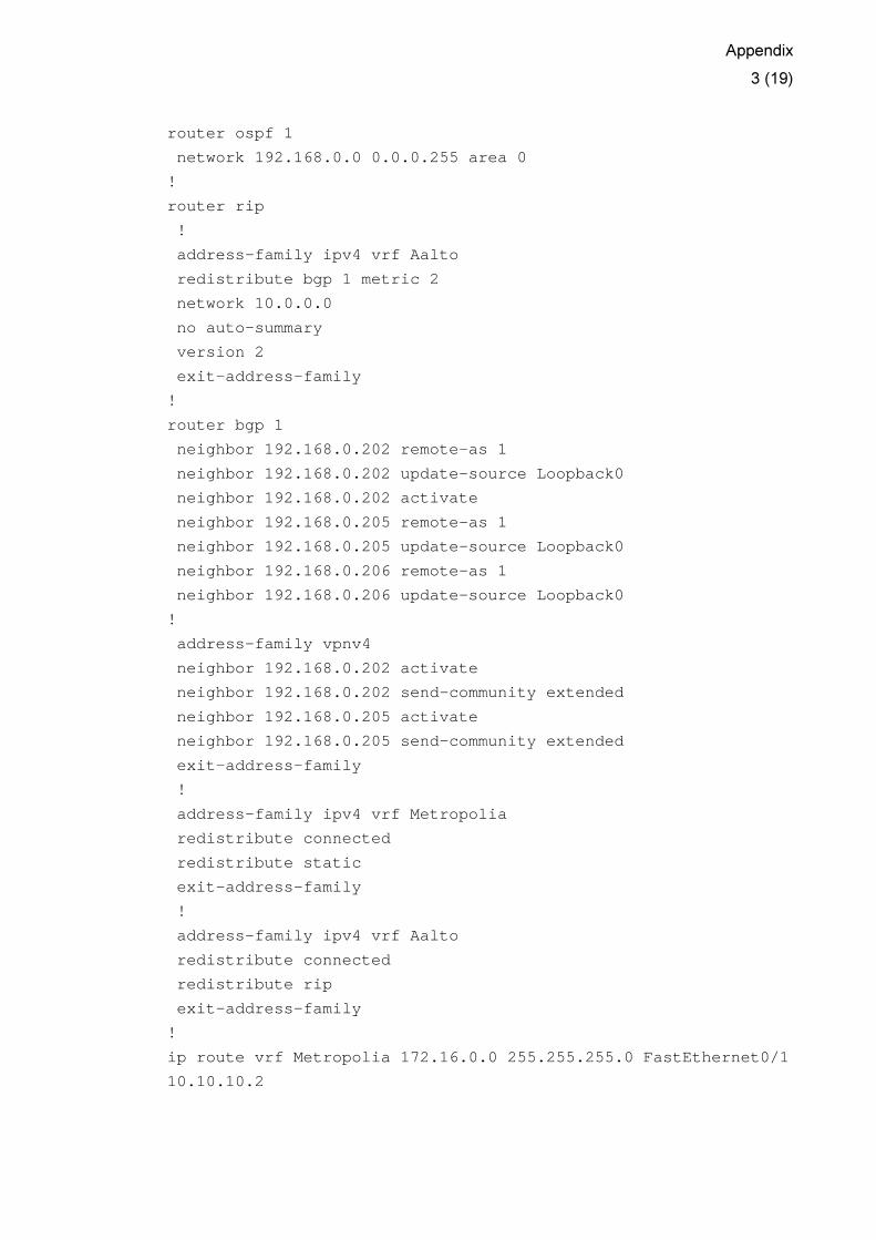
router ospf 1
network 192.168.0.0 0.0.0.255 area 0
!
router rip
!
address-family ipv4 vrf Aalto
redistribute bgp 1 metric 2
network 10.0.0.0
no auto-summary
version 2
exit-address-family
!
router bgp 1
neighbor 192.168.0.202 remote-as 1
neighbor 192.168.0.202 update-source Loopback0
neighbor 192.168.0.202 activate
neighbor 192.168.0.205 remote-as 1
neighbor 192.168.0.205 update-source Loopback0
neighbor 192.168.0.206 remote-as 1
neighbor 192.168.0.206 update-source Loopback0
!
address-family vpnv4
neighbor 192.168.0.202 activate
neighbor 192.168.0.202 send-community extended
neighbor 192.168.0.205 activate
neighbor 192.168.0.205 send-community extended
exit-address-family
!
address-family ipv4 vrf Metropolia
redistribute connected
redistribute static
exit-address-family
!
address-family ipv4 vrf Aalto
redistribute connected
redistribute rip
exit-address-family
!
ip route vrf Metropolia 172.16.0.0 255.255.255.0 Fa stEthernet0/1
10.10.10.2

Appendix
4 (19)
hostname PE2
!
ip cef
!
ip vrf Aalto
rd 1:3
route-target export 1:3
route-target import 1:3
!
ip vrf Helsinki
rd 1:4
route-target export 1:4
route-target export 200:4
route-target import 1:4
route-target import 200:4
!
interface Loopback0
ip address 192.168.0.202 255.255.255.255
!
interface FastEthernet0/0
ip address 192.168.0.22 255.255.255.252
mpls label protocol ldp
mpls ip
!
interface FastEthernet0/1
ip vrf forwarding Helsinki
ip address 10.30.30.5 255.255.255.252
!
interface FastEthernet1/0
ip vrf forwarding Aalto
ip address 10.30.30.1 255.255.255.252
!
router ospf 1
network 192.168.0.0 0.0.0.255 area 0
!
router rip
!
address-family ipv4 vrf Aalto
redistribute bgp 1 metric 2
network 10.0.0.0
no auto-summary
Appendix
5 (19)
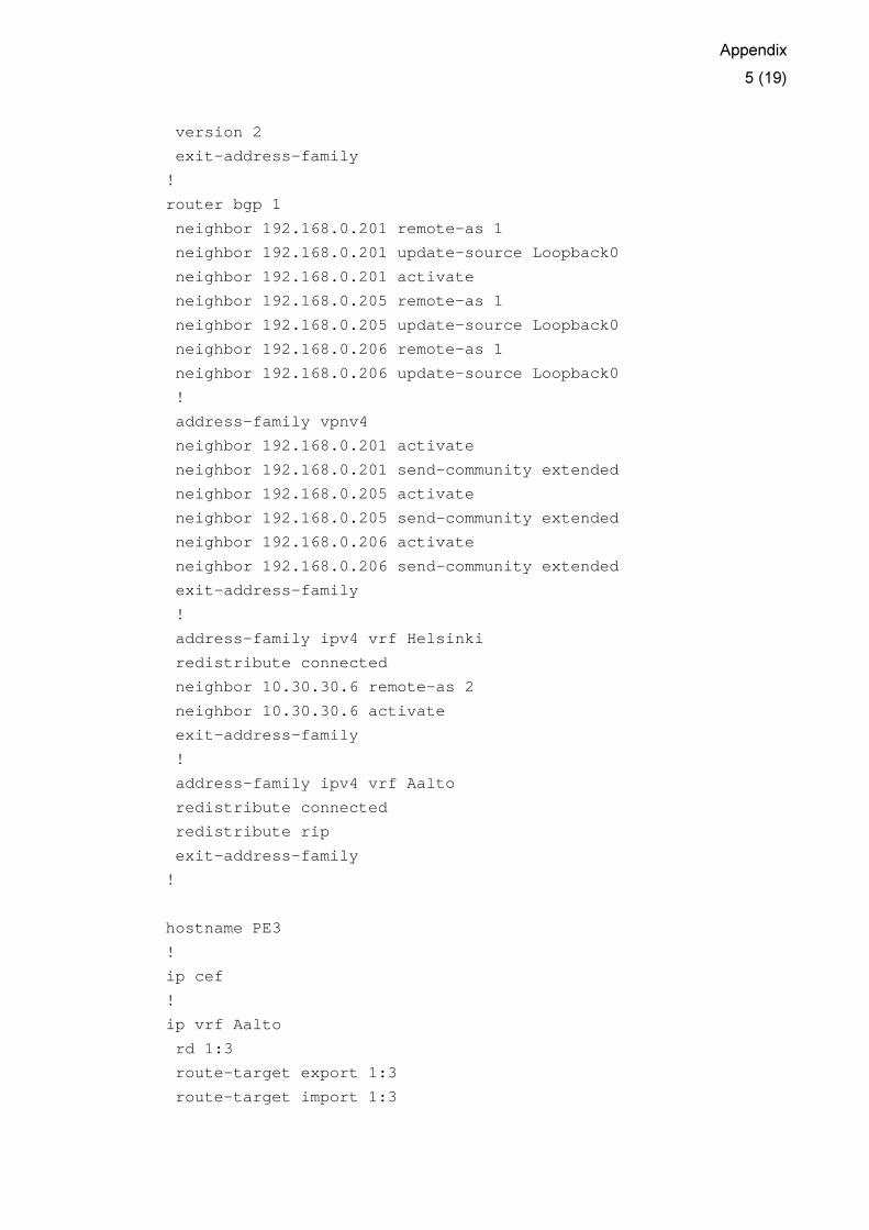
version 2
exit-address-family
!
router bgp 1
neighbor 192.168.0.201 remote-as 1
neighbor 192.168.0.201 update-source Loopback0
neighbor 192.168.0.201 activate
neighbor 192.168.0.205 remote-as 1
neighbor 192.168.0.205 update-source Loopback0
neighbor 192.168.0.206 remote-as 1
neighbor 192.168.0.206 update-source Loopback0
!
address-family vpnv4
neighbor 192.168.0.201 activate
neighbor 192.168.0.201 send-community extended
neighbor 192.168.0.205 activate
neighbor 192.168.0.205 send-community extended
neighbor 192.168.0.206 activate
neighbor 192.168.0.206 send-community extended
exit-address-family
!
address-family ipv4 vrf Helsinki
redistribute connected
neighbor 10.30.30.6 remote-as 2
neighbor 10.30.30.6 activate
exit-address-family
!
address-family ipv4 vrf Aalto
redistribute connected
redistribute rip
exit-address-family
!
hostname PE3
!
ip cef
!
ip vrf Aalto
rd 1:3
route-target export 1:3
route-target import 1:3
Appendix
6 (19)
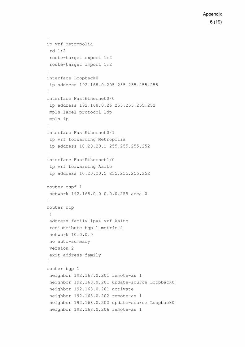
!
ip vrf Metropolia
rd 1:2
route-target export 1:2
route-target import 1:2
!
interface Loopback0
ip address 192.168.0.205 255.255.255.255
!
interface FastEthernet0/0
ip address 192.168.0.26 255.255.255.252
mpls label protocol ldp
mpls ip
!
interface FastEthernet0/1
ip vrf forwarding Metropolia
ip address 10.20.20.1 255.255.255.252
!
interface FastEthernet1/0
ip vrf forwarding Aalto
ip address 10.20.20.5 255.255.255.252
!
router ospf 1
network 192.168.0.0 0.0.0.255 area 0
!
router rip
!
address-family ipv4 vrf Aalto
redistribute bgp 1 metric 2
network 10.0.0.0
no auto-summary
version 2
exit-address-family
!
router bgp 1
neighbor 192.168.0.201 remote-as 1
neighbor 192.168.0.201 update-source Loopback0
neighbor 192.168.0.201 activate
neighbor 192.168.0.202 remote-as 1
neighbor 192.168.0.202 update-source Loopback0
neighbor 192.168.0.206 remote-as 1
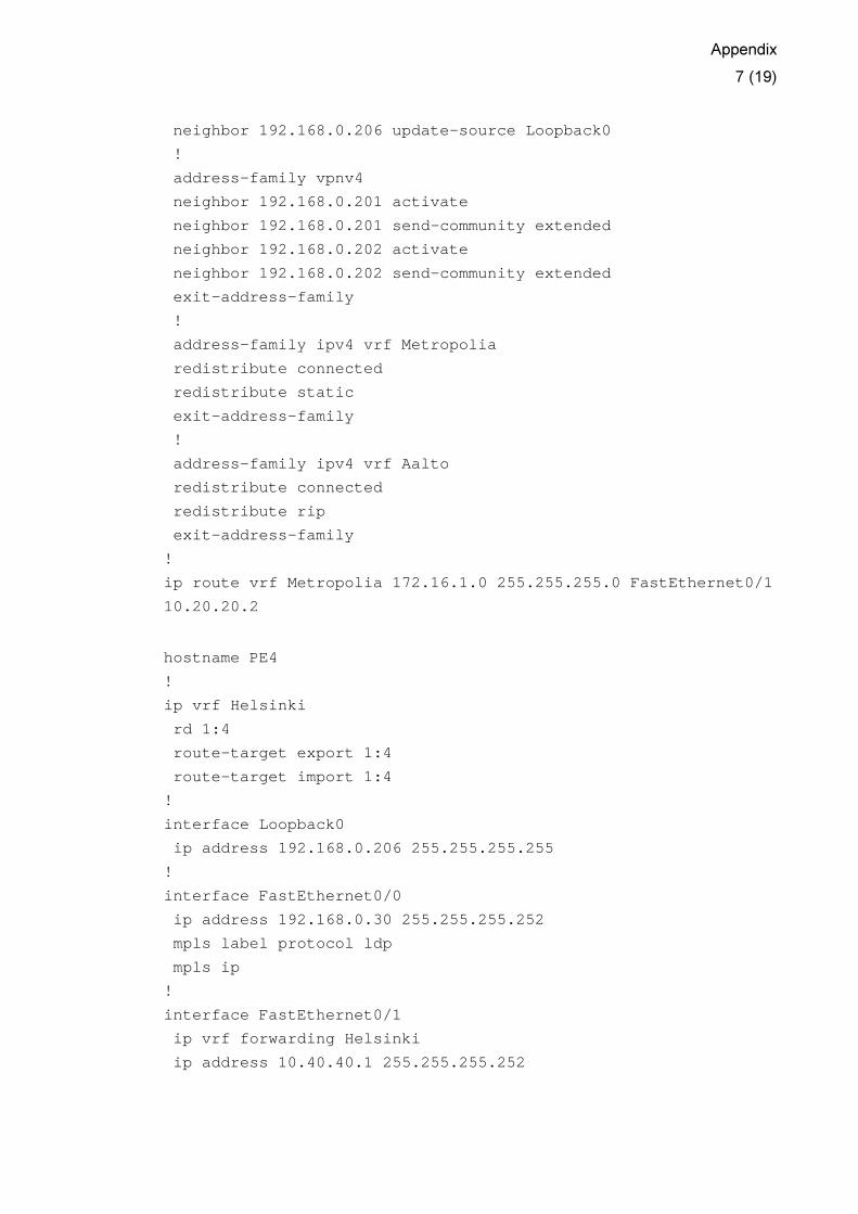
Appendix
7 (19)
neighbor 192.168.0.206 update-source Loopback0
!
address-family vpnv4
neighbor 192.168.0.201 activate
neighbor 192.168.0.201 send-community extended
neighbor 192.168.0.202 activate
neighbor 192.168.0.202 send-community extended
exit-address-family
!
address-family ipv4 vrf Metropolia
redistribute connected
redistribute static
exit-address-family
!
address-family ipv4 vrf Aalto
redistribute connected
redistribute rip
exit-address-family
!
ip route vrf Metropolia 172.16.1.0 255.255.255.0 Fa stEthernet0/1
10.20.20.2
hostname PE4
!
ip vrf Helsinki
rd 1:4
route-target export 1:4
route-target import 1:4
!
interface Loopback0
ip address 192.168.0.206 255.255.255.255
!
interface FastEthernet0/0
ip address 192.168.0.30 255.255.255.252
mpls label protocol ldp
mpls ip
!
interface FastEthernet0/1
ip vrf forwarding Helsinki
ip address 10.40.40.1 255.255.255.252
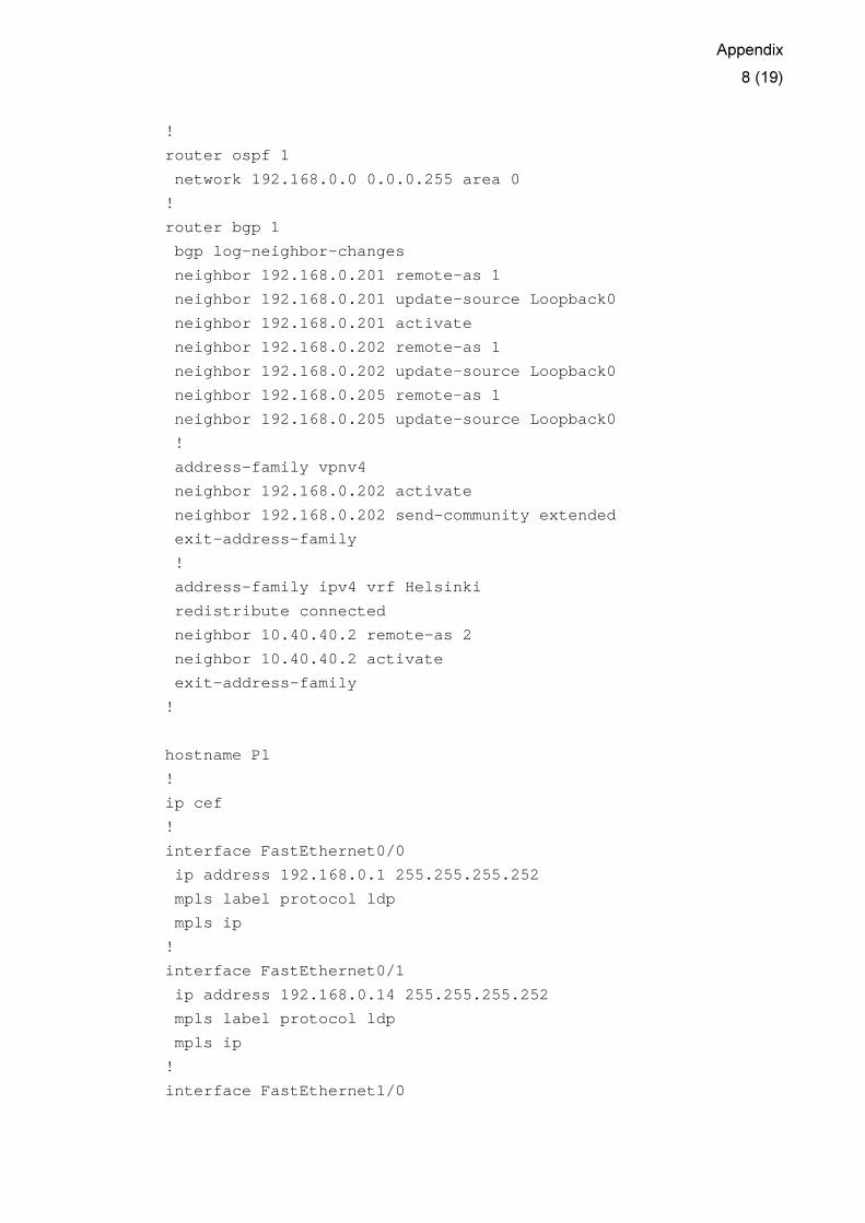
Appendix
8 (19)
!
router ospf 1
network 192.168.0.0 0.0.0.255 area 0
!
router bgp 1
bgp log-neighbor-changes
neighbor 192.168.0.201 remote-as 1
neighbor 192.168.0.201 update-source Loopback0
neighbor 192.168.0.201 activate
neighbor 192.168.0.202 remote-as 1
neighbor 192.168.0.202 update-source Loopback0
neighbor 192.168.0.205 remote-as 1
neighbor 192.168.0.205 update-source Loopback0
!
address-family vpnv4
neighbor 192.168.0.202 activate
neighbor 192.168.0.202 send-community extended
exit-address-family
!
address-family ipv4 vrf Helsinki
redistribute connected
neighbor 10.40.40.2 remote-as 2
neighbor 10.40.40.2 activate
exit-address-family
!
hostname P1
!
ip cef
!
interface FastEthernet0/0
ip address 192.168.0.1 255.255.255.252
mpls label protocol ldp
mpls ip
!
interface FastEthernet0/1
ip address 192.168.0.14 255.255.255.252
mpls label protocol ldp
mpls ip
!
interface FastEthernet1/0

Appendix
9 (19)
ip address 192.168.0.17 255.255.255.252
mpls label protocol ldp
mpls ip
!
router ospf 1
network 0.0.0.0 255.255.255.255 area 0
!
hostname P2
!
ip cef
!
interface FastEthernet0/0
ip address 192.168.0.5 255.255.255.252
mpls label protocol ldp
mpls ip
!
interface FastEthernet0/1
ip address 192.168.0.2 255.255.255.252
mpls label protocol ldp
mpls ip
!
interface FastEthernet1/0
ip address 192.168.0.21 255.255.255.252
mpls label protocol ldp
mpls ip
!
router ospf 1
network 0.0.0.0 255.255.255.255 area 0
!
hostname P3
!
ip cef
!
interface FastEthernet0/0
ip address 192.168.0.6 255.255.255.252
mpls label protocol ldp
mpls ip
!
interface FastEthernet0/1
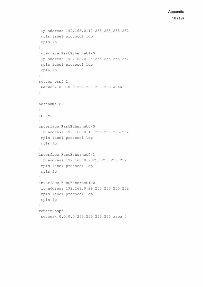
Appendix
10 (19)
ip address 192.168.0.10 255.255.255.252
mpls label protocol ldp
mpls ip
!
interface FastEthernet1/0
ip address 192.168.0.25 255.255.255.252
mpls label protocol ldp
mpls ip
!
router ospf 1
network 0.0.0.0 255.255.255.255 area 0
!
hostname P4
!
ip cef
!
interface FastEthernet0/0
ip address 192.168.0.13 255.255.255.252
mpls label protocol ldp
mpls ip
!
interface FastEthernet0/1
ip address 192.168.0.9 255.255.255.252
mpls label protocol ldp
mpls ip
!
interface FastEthernet1/0
ip address 192.168.0.29 255.255.255.252
mpls label protocol ldp
mpls ip
!
router ospf 1
network 0.0.0.0 255.255.255.255 area 0

Appendix
11 (19)
Appendix 2: Central Services Topology - Example
We are going to use the same MPLS VPN network implemented in Appendix 1 with its
full configuration commands. In this appendix, we will only present the configuration
commands needed to implement Central Services Topology.
Router Interface IP Address Subnet Mask
PE4 F1/0 10.40.40.5 255.255.255.252
Configuration Commands:
hostname PE4
!
ip vrf MetroServer
rd 1:10
route-target both 1:20 ! Server_RT
route-target import 1:40 ! Client_RT
!
ip vrf Helsinki
route-target import 1:20 ! Server_RT
route-target export 1:40 ! Client_RT
!
interface FastEthernet1/0
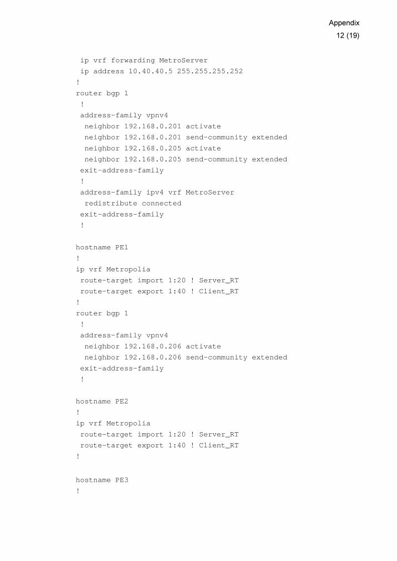
Appendix
12 (19)
ip vrf forwarding MetroServer
ip address 10.40.40.5 255.255.255.252
!
router bgp 1
!
address-family vpnv4
neighbor 192.168.0.201 activate
neighbor 192.168.0.201 send-community extended
neighbor 192.168.0.205 activate
neighbor 192.168.0.205 send-community extended
exit-address-family
!
address-family ipv4 vrf MetroServer
redistribute connected
exit-address-family
!
hostname PE1
!
ip vrf Metropolia
route-target import 1:20 ! Server_RT
route-target export 1:40 ! Client_RT
!
router bgp 1
!
address-family vpnv4
neighbor 192.168.0.206 activate
neighbor 192.168.0.206 send-community extended
exit-address-family
!
hostname PE2
!
ip vrf Metropolia
route-target import 1:20 ! Server_RT
route-target export 1:40 ! Client_RT
!
hostname PE3
!

Appendix
13 (19)
ip vrf Metropolia
route-target import 1:20 ! Server_RT
route-target export 1:40 ! Client_RT
!
router bgp 1
!
address-family vpnv4
neighbor 192.168.0.206 activate
neighbor 192.168.0.206 send-community extended
exit-address-family
!
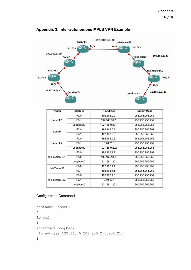
Appendix
14 (19)
Appendix 3: Inter-autonomous MPLS VPN Example
Router Interface IP Address Subnet Mask
F0/0 192.168.0.2 255.255.255.252
F0/1 192.168.10.2 255.255.255.252 SabaPE1
Loopback0 192.168.0.201 255.255.255.255
F0/0 192.168.0.1 255.255.255.252 SabaP
F0/1 192.168.0.5 255.255.255.252
F0/0 192.168.0.6 255.255.255.252
F0/1 10.20.20.1 255.255.255.252 SabaPE2
Loopback0 192.168.0.202 255.255.255.255
F0/0 192.168.1.2 255.255.255.252
F1/0 192.168.10.1 255.255.255.252 teleYemenPE1
Loopback0 192.168.1.201 255.255.255.255
F0/0 192.168.1.1 255.255.255.252 teleYemenP
F0/1 192.168.1.5 255.255.255.252
F0/0 192.168.1.6 255.255.255.252
F0/1 10.10.10.1 255.255.255.252 teleYemenPE2
Loopback0 192.168.1.202 255.255.255.255
Configuration Commands:
hostname SabaPE1
!
ip cef
!
interface Loopback0
ip address 192.168.0.201 255.255.255.255
!

Appendix
15 (19)
interface FastEthernet0/0
ip address 192.168.0.2 255.255.255.252
mpls label protocol ldp
mpls ip
!
interface FastEthernet0/1
ip address 192.168.10.2 255.255.255.252
!
router ospf 1
network 192.168.0.0 0.0.0.255 area 0
!
router bgp 2
no bgp default ipv4-unicast
no bgp default route-target filter
neighbor 192.168.0.202 remote-as 2
neighbor 192.168.0.202 update-source Loopback0
neighbor 192.168.10.1 remote-as 1
!
address-family vpnv4
neighbor 192.168.0.202 activate
neighbor 192.168.0.202 send-community extended
neighbor 192.168.0.202 next-hop-self
neighbor 192.168.10.1 activate
neighbor 192.168.10.1 send-community extended
exit-address-family
!
hostname SabaP
!
ip cef
!
interface FastEthernet0/0
ip address 192.168.0.1 255.255.255.252
mpls label protocol ldp
mpls ip
!
interface FastEthernet0/1
ip address 192.168.0.5 255.255.255.252
mpls label protocol ldp
mpls ip
!
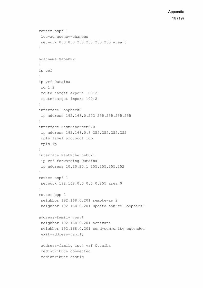
Appendix
16 (19)
router ospf 1
log-adjacency-changes
network 0.0.0.0 255.255.255.255 area 0
!
hostname SabaPE2
!
ip cef
!
ip vrf Qutaiba
rd 1:2
route-target export 100:2
route-target import 100:2
!
interface Loopback0
ip address 192.168.0.202 255.255.255.255
!
interface FastEthernet0/0
ip address 192.168.0.6 255.255.255.252
mpls label protocol ldp
mpls ip
!
interface FastEthernet0/1
ip vrf forwarding Qutaiba
ip address 10.20.20.1 255.255.255.252
!
router ospf 1
network 192.168.0.0 0.0.0.255 area 0
!
router bgp 2
neighbor 192.168.0.201 remote-as 2
neighbor 192.168.0.201 update-source Loopback0
!
address-family vpnv4
neighbor 192.168.0.201 activate
neighbor 192.168.0.201 send-community extended
exit-address-family
!
address-family ipv4 vrf Qutaiba
redistribute connected
redistribute static

Appendix
17 (19)
exit-address-family
!
ip route vrf Qutaiba 172.16.0.0 255.255.255.0 FastE thernet0/1
10.20.20.2
hostname teleYemenPE1
!
ip cef
!
interface Loopback0
ip address 192.168.1.201 255.255.255.252
!
interface FastEthernet0/0
ip address 192.168.1.2 255.255.255.252
mpls label protocol ldp
mpls ip
!
interface FastEthernet0/1
ip address 192.168.10.1 255.255.255.252
!
router ospf 1
network 192.168.1.0 0.0.0.255 area 0
!
router bgp 1
no bgp default ipv4-unicast
no bgp default route-target filter
neighbor 192.168.1.202 remote-as 1
neighbor 192.168.1.202 update-source Loopback0
neighbor 192.168.10.2 remote-as 2
!
address-family vpnv4
neighbor 192.168.1.202 activate
neighbor 192.168.1.202 send-community extended
neighbor 192.168.1.202 next-hop-self
neighbor 192.168.10.2 activate
neighbor 192.168.10.2 send-community extended
exit-address-family
!
hostname teleYemenP
!

Appendix
18 (19)
ip cef
!
interface FastEthernet0/0
ip address 192.168.1.1 255.255.255.252
mpls label protocol ldp
mpls ip
!
interface FastEthernet0/1
ip address 192.168.1.5 255.255.255.252
mpls label protocol ldp
mpls ip
!
router ospf 1
network 0.0.0.0 255.255.255.255 area 0
!
hostname teleYemenPE2
!
ip cef
!
ip vrf Qutaiba
rd 1:2
route-target export 100:2
route-target import 100:2
!
interface Loopback0
ip address 192.168.1.202 255.255.255.255
!
interface FastEthernet0/0
ip address 192.168.1.6 255.255.255.252
mpls label protocol ldp
mpls ip
!
interface FastEthernet0/1
ip vrf forwarding Qutaiba
ip address 10.10.10.1 255.255.255.252
!
router ospf 1
network 192.168.1.0 0.0.0.255 area 0
!
router bgp 1
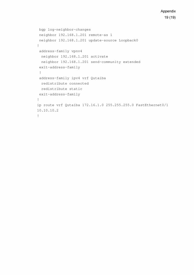
Appendix
19 (19)
bgp log-neighbor-changes
neighbor 192.168.1.201 remote-as 1
neighbor 192.168.1.201 update-source Loopback0
!
address-family vpnv4
neighbor 192.168.1.201 activate
neighbor 192.168.1.201 send-community extended
exit-address-family
!
address-family ipv4 vrf Qutaiba
redistribute connected
redistribute static
exit-address-family
!
ip route vrf Qutaiba 172.16.1.0 255.255.255.0 FastE thernet0/1
10.10.10.2
!