mppic model implementation in mfix: frictional …...mppic model implementation in mfix: frictional...
TRANSCRIPT

MPPIC model implementation in MFIX: frictional solid-stress model Rahul Garg1,2
, J. F. Dietiker1,3, and M. Shahnam1 1: National Energy Technology Laboratory 2: URS Corp. 3: WVURC

2
Comparison b/w different discrete methods
D = 1
D = 1, W = 5 D = 51/3
MPPIC (CPFD-Barracuda, FLUENT DP-DPM)
Collisions modeled
Coarse-Grain DEM (Joseph and Patankar,
IJMF’01) Direct collisions
DEM (Hard-sphere, soft-sphere, MD)
Direct-collisions

3
MPPIC: current state-of-the-art
“IT WORKS!!!” “IT’S FAST” Demonstrated to be a useful tool for quick
turnaround simulations at pilot/device scales Several commercial implementations (Barracuda by
CPFD, Dense-phase-DPM by ANSYS) Hard to ascertain and further develop sub-models
(such as collision, friction, etc.) Confusion among users regarding the exact form of
models Objective of this study: understand, implement, and
document MPPIC model in open-source MFIX code to probe its accuracy and speed

4
MPPIC model details
Carrier Phase: averaged Navier-Stokes equation
Dispersed Phase
Acoll is the collision operator used to model collisions in the k inetic and frictional regimes. Robust implementation of frictional regime Acoll is critical to stability of MPPIC model

5
Particle trajectory evolution
How is Acoll applied ?
Impulse velocity
Drag+body force

6
Acoll implementation (frictional regime)
is like a coloring function used to indicate the close-packed regions. is non-zero inside and at the interfaces of close-packed regions. It only indicates the direction of the correction due to close-packing.

7
Acoll implementation Case 1 Case 2 Case 3 Case 4

8
Acoll implementation (Summary) Case 1
+
Case 1b

9
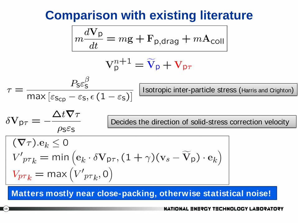
Comparison with existing literature
Snider, D. M., An incompressible 3-D MP-PIC model for dense particle flows, JCP (2001)
No inter-particle collision term so far
10
Isotropic inter-particle stress (Harris and Crighton)
Decides the direction of solid-stress correction velocity
Matters mostly near close-packing, otherwise statistical noise!
Comparison with existing literature

11
Comparison with existing literature

12
Case 1 Case 2 Case 3 Case 4
Explanation of limiters

13
Snider’s model vs. the new model
Case 1b
+

14
STILL DOESN’T WORK!
A simple case of particles sedimenting in a vertical channel blows up due to the inability of the frictional model to sustain
specified close-packing

15
Fix? Case 1b
+
Case 1a
+
Cases 1-4
Results in unconditionally stable solver (does not guarantee any results) Still a 2-parameter model

16
Other features/limitations/future development
Specular reflections at wall No friction at the walls No collisions in the viscous regime Robust extension to cut-cell

17
Model development thought process
Three problems were chosen: sedimentation, spouted bed, and uniformly fluidized bed
Any frictional model or a wild guess was tested by running all three problems Lot of times very encouraging results for one problem
led to blow up of simulations for other problems A stable model did not always imply a physically
plausible model. The first model I tried was the most stable one but nothing really moved in that model either!
The final model is a trade off between numerical stability and physics. There are many other variants of this model possible…..

18
Sample Problem 1: Kuiper’s jet
Properties
Solids: Dp = 0.05 cm, ρp = 2.6 g/cm3
Total number of particles (DEM) = 36 million Total number of parcels (MPPIC) = 4,560 ~ 8000 particles per parcel Gas: Air at standard conditions
Bed Dimension= (57x100x1.5) cm3 ≡ (31x60x1) cells
No slip wall BC’s for gas and free slip for solids phase mean velocity Drag model: Wen & Yu / Ergun Pressure of bed weight = 7.1 kPa
10 m/s 0.25 m/s
Kuipers, J.A.M., A two-fluid micro balance of fluidized bed. PhD thesis, 1990
Easiest to bubble, hardest to simulate stably

19
TFM vs MPPIC vs CPFD
TFM MFIX-PIC CPFD

20
Pressure Drop
Both MFIX-PIC and CPFD exhibit different bubble frequency with CPFD giving the lowest bubble frequency The amplitude of oscillations is higher in CPFD implying prediction of higher pressure fluctuations for design purposes
Under-prediction of pressure drop by 15% for the best case. Pressure drop most sensitive to first frictional coefficient of restitution. Week dependence on second frictional coefficient of restitution Recommended values of 0.3-0.6 for both parameters COMPUTATIONAL WALL TIMES: TFM (400 mins), and MPPIC (80 mins) on a single core.

21
Effect of frictional coefficient’s of restitution
The model’s stability does not get affected by the first coefficient of restitution. Recommended values of 0.3-0.6 for both parameters
22
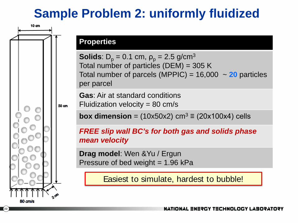
Sample Problem 2: uniformly fluidized
Properties
Solids: Dp = 0.1 cm, ρp = 2.5 g/cm3
Total number of particles (DEM) = 305 K Total number of parcels (MPPIC) = 16,000 ~ 20 particles per parcel Gas: Air at standard conditions Fluidization velocity = 80 cm/s box dimension = (10x50x2) cm3 ≡ (20x100x4) cells
FREE slip wall BC’s for both gas and solids phase mean velocity
Drag model: Wen &Yu / Ergun Pressure of bed weight = 1.96 kPa
Easiest to simulate, hardest to bubble!
23
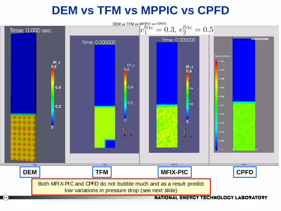
DEM vs TFM vs MPPIC vs CPFD
Both MFIX-PIC and CPFD do not bubble much and as a result predict low variations in pressure drop (see next slide)
DEM MFIX-PIC CPFD TFM

25
Pressure drop comparison
26
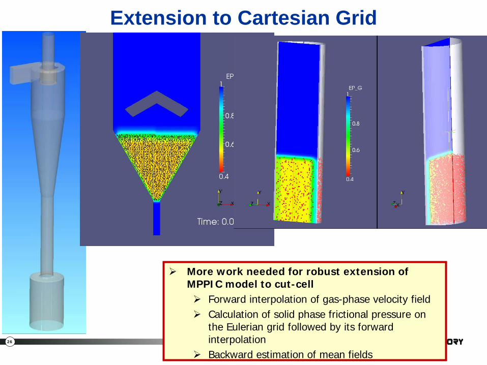
Extension to Cartesian Grid
More work needed for robust extension of MPPIC model to cut-cell Forward interpolation of gas-phase velocity field Calculation of solid phase frictional pressure on
the Eulerian grid followed by its forward interpolation
Backward estimation of mean fields
27
Conclusions/Observations
MPPIC model implemented in open-source MFIX code A new limiter based on physical arguments
formulated for solid-stress model MPPIC model compared against other CFD models
and existing commercial MPPIC model MPPIC models found to be in qualitative and limited
quantitative agreements with the more accurate DEM model
Need to implement additional physical models for particle-particle and particle-wall interactions

28
Acknowledgments
This technical effort was performed in support of the National Energy Technology Laboratory’s ongoing research in advanced numerical simulation
of multiphase flow under the RES contract DE-FE0004000.