mr-j3-t servo amplifier with point table positioning
TRANSCRIPT

MR-J3-T
Servo Amplifier
Quick Start Manual
MR-J3-T Servo AmplifierWith Point Table Positioning
(Point-to-Point Positioning)
Art. No.: xxxxxx21122007Version A
MITSUBISHI ELECTRIC
MITSUBISHI ELECTRIC INDUSTRIAL AUTOMATION


About This Manual
If you have any questions about programming or operating the equipmentdescribed in this manual please don’t hesitate to contact your dealer or
one of our official distributors (see back cover).
You can find up-to-date information and answers to frequently-askedquestions on our website (www.mitsubishi-automation.com).
MITSUBISHI ELECTRIC EUROPE B.V. reserves the right to maketechnical changes to the products or this manual at any time without prior
notice.
© December 2007MITSUBISHI ELECTRIC EUROPE B.V.


Quick Start ManualMR-J3-T Servo Amplifier with Integrated Point Table Positioning
Art. No.: xxxxxx
Version Changes / Additions / CorrectionsA 10/2007 pdp First Edition


This Quick Start Manual for the servo amplifiers of the MR-J3-T series with point table positio-ning is designed to enable you to get your system installed and configured for use as quickly aspossible. Please note that this guide only covers the basic functions with the instructions neces-sary to use these functions. Complete descriptions of all the supported functions and all availa-ble extensions can be found in the instruction manuals.
Please also note that the servo amplifiers of the MR-J3-T series include the following additionalmajor functions that are not covered in this Quick Start Manual:
� Communication via a serial port for controlling point table positioning
� Positioning control in BCD format with the optional MR-DS60 digital switch
� Amplifier controller circuit settings and auto-tuning functions
Safety Instructions
To ensure safe and proper installation of the equipment please also observe the instructions andsafety precautions in the instruction manuals supplied for your hardware.
Notes in this Quick Start Manual:
NOTE Tips and useful information.
Additional documentation:
� MR-J3-T Instruction Manual (SH(NA030061-A)
� MR-J3-T Instruction Manual for CC-Link (SH(NA030058-B)
� Instruction Manual for the CC-Link Master Module:
– QJ61BT11N
– A1SJ61BT11
– A1SJ61QBT11
– FX2N-16CCL-M
MR-J3-T i

Contents
ii MITSUBISHI ELECTRIC
1 Introduction
1.1 Preparations . . . . . . . . . . . . . . . . . . . . . . . . . . . . . . . . . . . . . . . . . . . . . . . . . . . . .1-1
2 Installing the Equipment
2.1 Installing the MR-J3-D01 Extension . . . . . . . . . . . . . . . . . . . . . . . . . . . . . . . . . . .2-3
3 First Functional Test
3.1 Minimum Connections for the Functional Check . . . . . . . . . . . . . . . . . . . . . . . . . . . . . 3-5
3.1.1 Connector pin assignments. . . . . . . . . . . . . . . . . . . . . . . . . . . . . . . . . . .3-6
3.2 Functional Test Settings. . . . . . . . . . . . . . . . . . . . . . . . . . . . . . . . . . . . . . . . . . . . .3-7
3.3 Configuring Positioning Point Tables . . . . . . . . . . . . . . . . . . . . . . . . . . . . . . . . . . .3-9
3.4 Functional Test with MR Configurator . . . . . . . . . . . . . . . . . . . . . . . . . . . . . . . . .3-10
3.4.1 Selecting point table position entries . . . . . . . . . . . . . . . . . . . . . . . . . . 3-10
4 Positioning with Digital Inputs
4.1 Additional Connections . . . . . . . . . . . . . . . . . . . . . . . . . . . . . . . . . . . . . . . . . . . .4-11
4.2 Turning off Automatic Input Signal Activation . . . . . . . . . . . . . . . . . . . . . . . . . . . 4-14
4.3 Home Position Return. . . . . . . . . . . . . . . . . . . . . . . . . . . . . . . . . . . . . . . . . . . . .4-15
4.3.1 Dogless Z-phase reference mode. . . . . . . . . . . . . . . . . . . . . . . . . . . . . 4-15
4.3.2 Dog mode home position return . . . . . . . . . . . . . . . . . . . . . . . . . . . . . .4-19
4.4 Configuration for Positioning . . . . . . . . . . . . . . . . . . . . . . . . . . . . . . . . . . . . . . . .4-23
4.4.1 Importing and exporting point tables. . . . . . . . . . . . . . . . . . . . . . . . . . . 4-26
4.5 Functional Test of Digital Input Positioning . . . . . . . . . . . . . . . . . . . . . . . . . . . . . .4-28
5 Positioning via a CC-Link Network
5.1 Additional Connections . . . . . . . . . . . . . . . . . . . . . . . . . . . . . . . . . . . . . . . . . . . .5-31
5.2 CC-Link Communication Settings . . . . . . . . . . . . . . . . . . . . . . . . . . . . . . . . . . . .5-33
5.2.1 Settings on the servo amplifier . . . . . . . . . . . . . . . . . . . . . . . . . . . . . . .5-33
5.2.2 Configuration for communication with GX IEC Developer . . . . . . . . . . 5-35
5.3 Testing the Servo Amplifier via CC-Link . . . . . . . . . . . . . . . . . . . . . . . . . . . . . . .5-37
A Appendix
A.1 Digital Signals − Quick Reference. . . . . . . . . . . . . . . . . . . . . . . . . . . . . . . . . . . .A-39
A.2 Standard Parameters − Quick Reference . . . . . . . . . . . . . . . . . . . . . . . . . . . . . .A-40
A.3 Alarms and Warning Messages . . . . . . . . . . . . . . . . . . . . . . . . . . . . . . . . . . . . . . .A-41

1 Introduction
The servo amplifiers of the MR-J3-T series are designed specifically for drive positioning appli-cations using point-to-point positioning without interpolation or trajectory control. The positionsto be accessed stored in a table and can be selected cyclically, individually or in any order with:
� Digital signals
� CC-Link communication
The MR Configurator setup software package enables the user to test the entered positioningsteps quickly and easily in test mode.
1.1 Preparations
The following products and parts are needed for using the point table positioning fea-tures described in this manual:
� A servo amplifier, for example MR-J3-10T
� A servo motor compatible with the selected amplifierExample: HF-KP13 motor for the MR-J3-10T servo amplifier
� MRZJW3-SETUP221E Version C0 of the MR Configurator setup software package
� MR-J3USBCBL3M USB cable for connecting your PC/notebook with the servo amplifier
� MR-PWS1CBL M-A1-L motor connection cable
� MR-J3ENCBL M-A2-L rotary encoder cable
� MR-J2CMP2 connector for CN6 I/O signal connector
� Power supply cables conforming to the applicable installation regulations
� Connection cables for the control terminals
Required for positioning control with digital signals:
� MR-J3CN1 connector for communication connector CN10
� Optional MR-J3-D01 expansion card
Useful but not absolutely necessary:
� Simulation Box and terminal block with connection cable for testing:FX Simulation Box (Art. No. 3386)MR-TB50 terminal block for CN10 (MR-J3-D01)MR-J2M-CN1TBL•M cable for connecting CN10 to MR-TB50
Introduction Preparations
MR-J3-T 1 - 1

Required for positioning control via a CC-Link network:
� Q-Rack with PLC and the CC-Link module QJ61BT11NorA–Rack with PLC and CC-Link module A1SJ61BT11,A1SJ61QBT11 or FX2N-16CCL-M
� CC-Link cable compatible with version V1.10 Standard
� Cable for connecting the PC/notebook to the PLC CPU:Q series: SC-Q QC30R2A and FX series: SC-09
� The GX IEC Developer programming software package for configuration of the data com-munications settings
NOTE This Quick Start Manual describes the installation and setup of a typical servo system con-sisting of an MR-J3-10T servo amplifier (single-phase, 230V / 100W) and an HF-KP13 ser-vo motor. Note that the specifications of this sample system may differ from those of yourconfiguration – please check your equipment’s instruction manuals for details if necessary.
Preparations Introduction
1 - 2 MITSUBISHI ELECTRIC

2 Installing the Equipment
The procedure for the physical installation of the MR-J3-T series hardware is exactly the sameas for the MR-J3-A and MR-J3-B models. The dimensions of the MR-J3-T series amplifiers areidentical to those of the matching models of the MR-J3-A and MR-J3-B series.
NOTE Please consult the instruction manual for detailed installation instructions.
2.1 Installing the MR-J3-D01 Extension
Procedure:
� Remove the cover of the CN7 connector on the right side of the MR-J3-T housing.
� Position the MR-J3-D01 extension over the upper and lower mounting points 1 on the ser-vo amplifier, then press the extension into place so that the lugs click into position in the up-per and lower mounting points 2. This also connects the extension to the amplifier via con-nector CN7 on the amplifier.
� Fasten the extension securely to the servo amplifier with the M4 screw (included) asshown in Fig. 2-2.
Installing the Equipment Installing the MR-J3-D01 Extension
MR-J3-T 2 - 3
Fig. 2-1: Fixing points of the extension MR-J3-D01
Upper mounting
point 2
Cover for CN7connector
Upper mountingpoint 1
Lower mountingpoint 1
Lower mountingpoint 2

NOTE To uninstall the extension perform the above steps in the reverse order. To release the retai-ning clips press the retaining tabs marked “Push” inwards and pull the extension out to theside.
Installing the MR-J3-D01 Extension Installing the Equipment
2 - 4 MITSUBISHI ELECTRIC
Fig. 2-2: Fastening screw dimensions for extension MR-J3-D01

3 First Functional Test
The wiring diagram below (Fig. 3-1) shows the minimum connections that you must make to testan MR-J3-T series amplifier with the MR Configurator setup software. In test mode you cancheck whether all the components are working properly.
NOTE You can also use the optional MR-PRU-03 HMI control terminal for performing initial testsand setting the amplifier’s parameters.For further details see the MR-J3-T series instructionmanual.
3.1 Minimum Connections for the Functional Check
First Functional Test Minimum Connections for the Functional Check
MR-J3-T 3 - 5
Fig. 3-1: Wiring diagram for minimum configuration without control terminals
1-phase200–230V AC
Servo motor
Motor

3.1.1 Connector pin assignments
Minimum Connections for the Functional Check First Functional Test
3 - 6 MITSUBISHI ELECTRIC
Fig. 3-2: Power and control connector pin assignments for minimum configuration
Power terminals Servo amplifierMR-J3-�T
USBport
I/O extensionMR-J3-D01
Connector CN2

3.2 Functional Test Settings
The following input signals are required to activate the servo amplifier’s motor output:
� EMG -> Force stop (safety signal)
� SON -> Servo ON
� LSP -> Forward rotation stroke end (limit switch)
� LSN -> Reverse rotation stroke end (limit switch)
You can configure the servo amplifier to activate these signals automatically when the power isswitched on:
Procedure:
� Connect the PC / notebook to the servo amplifier’s USB port (CN5) with theMR-J3USBCBL3M cable.
� Start MR Configurator on the computer and make the following settings:
– Select the MR-J3-T series servo amplifier:
First Functional Test Functional Test Settings
MR-J3-T 3 - 7
Fig. 3-3: Selecting the servo amplifier
�
�
�

– Set the parameter for the automatic activation of the EMG, SON and LSP/LSN inputsignals:
Parameter PD01 “Input signal automatic ON selection 1” = 1C04
– Turn the servo amplifier off and then turn it on again to initialise the new parameter set-ting.
Functional Test Settings First Functional Test
3 - 8 MITSUBISHI ELECTRIC
Fig. 3-4: Parameter settings for automatic input signal activation.
�
�
�

3.3 Configuring Positioning Point Tables
The position values, travel speeds and acceleration and deceleration times are stored in tablesknown as “point tables”. We will now go through the steps required to configure and define apoint table.
Procedure:
� Select the Point Table option from the Point-data menu.� Enter the values for the movements (position, speed, acceleration and deceleration times)
in the Point Table List window, using one line for each movement:
– Enter target position (a) in µm x 10STM (STM: e in diagram).
– Enter speed (b) in rpm.
– Enter acceleration/deceleration times (c) and (d) in ms as required for the motor’s ratedspeed.
� Save the entries by clicking on the Write All button.
Make sure that the Aux. Func. value in every line is left at the default factory setting (“0”) toensure that selecting a position value in the table does not inadvertently activate any subse-quent table entries.
NOTES In the factory default settings the absolute value command system for the target positions isactivated with parameter PA01 “*STY”. When this system is active all target position valuesare referred to the physical home position. Alternatively you can also select the incrementalvalue command system. The absolute position detection system for the home return func-tion can be set with parameter PA03 “*ABS” (see chapter 4.3).
Loading the factory defaults will not overwrite your point table entries.
First Functional Test Configuring Positioning Point Tables
MR-J3-T 3 - 9
Fig. 3-5: Point table positioning entries in the point table list window
�
�
a
{�e
b c d

3.4 Functional Test with MR Configurator
Using MR Configurator you can perform a basic test of the individual positioning steps and makeadjustments for your application. Note that setting parameter PA14 does not have any effect onthe rotation direction in jog mode when using MR Configurator. The rotation directions aredefined as follows, looking at the end of the drive shaft (i.e. towards the motor):
� FORWARD -> anticlockwise
� REVERSE -> clockwise
NOTES Home position return is not possible in test mode when using MR Configurator – use the jogfunction to move to the starting position.
You can set the rotation direction in “single-step feed mode” with parameter PA14.
3.4.1 Selecting point table position entries
Procedure:
� Select Single-step Feed � in the Test menu.� To select a position enter its point table line number in the dialog box displayed �.� Start the positioning operation �.
Functional Test with MR Configurator First Functional Test
3 - 10 MITSUBISHI ELECTRIC
Fig. 3-6: Single-step Feed window for testing individual positioning steps
�
�
�
4 Positioning with Digital Inputs
This chapter describes how point table positioning is used in most applications with the MR-J3-Tseries amplifiers and the MR-J3-D01 I/O extension.
NOTE Please refer to the instruction manual if you need other functions other than those describedhere for your application.
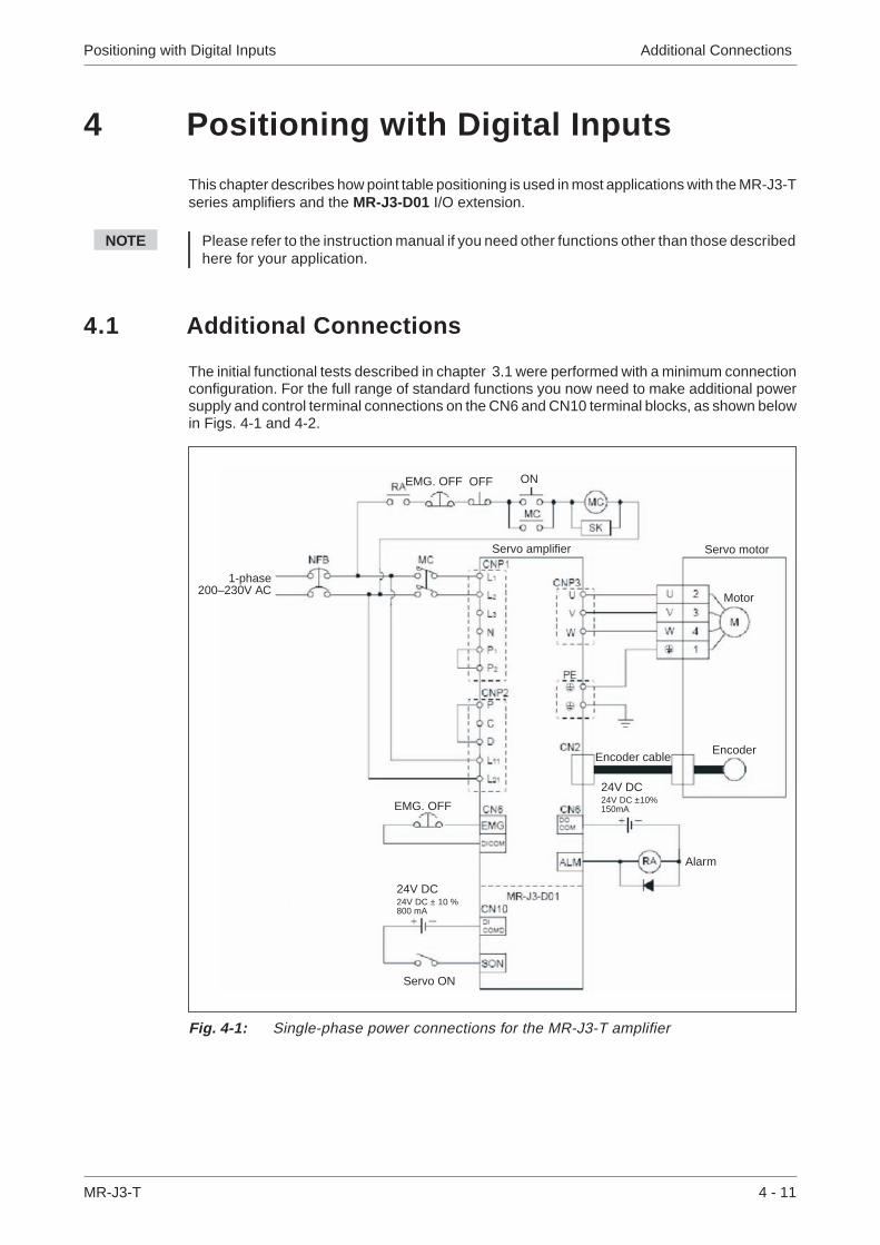
4.1 Additional Connections
The initial functional tests described in chapter 3.1 were performed with a minimum connectionconfiguration. For the full range of standard functions you now need to make additional powersupply and control terminal connections on the CN6 and CN10 terminal blocks, as shown belowin Figs. 4-1 and 4-2.
Positioning with Digital Inputs Additional Connections
MR-J3-T 4 - 11
Fig. 4-1: Single-phase power connections for the MR-J3-T amplifier
1-phase200–230V AC
Servo motor
Motor
EncoderEncoder cable
Alarm
EMG. OFF OFF ON
EMG. OFF
Servo ON
Servo amplifier
24V DC24V DC ± 10 %800 mA
24V DC24V DC ±10%150mA
Additional Connections Positioning with Digital Inputs
4 - 12 MITSUBISHI ELECTRIC
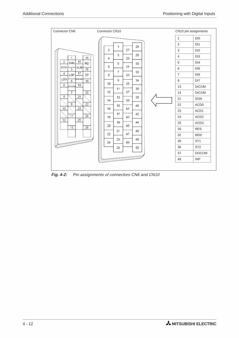
1 DI0
2 DI1
3 DI2
4 DI3
5 DI4
6 DI5
7 DI6
8 DI7
13 DICOM
14 DICOM
21 SON
22 ACD0
23 ACD1
24 ACD2
25 ACD3
26 RES
32 MD0
35 ST1
36 ST2
37 DOCOM
49 INP
Connector CN6 Connector CN10 CN10 pin assignments
Fig. 4-2: Pin assignments of connectors CN6 and CN10

NOTES You can find a brief descriptions of the signal functions in Appendix A.1. Please refer to theinstruction manual for a complete reference.
All digital signals described in this manual use source logic.
For safety reasons the EMG signal must be connected to pin 1 of connector CN6 if theservo amplifier is not operated during the first functional test. The EMG signal is perma-nently assigned to pin 1 and the amplifier is deactivated when there is no EMG signal if it isconfigured accordingly (see chapter 3.2).
Positioning with Digital Inputs Additional Connections
MR-J3-T 4 - 13
Fig. 4-3: Connection of the control terminals with PNP logic (source logic)
24V DC ±10%150mA �
24V DC
EMG. OFFProximity dog
Forward stroke endReverse stroke end
max. 10m
max. 10m
24V DC ±10%800mA �
24V DC
Pointtable
selection
SERVO ONRESET
Automatic/Manuall
Forward rotation startReverse rotation start
� A 24V 1000mA power supply can beused for all control terminals.
max. 10m
In position
Alarm code
MR-J3USBCBL3M
(Option)
max.10 m

4.2 Turning off Automatic Input Signal Activation
Procedure:
� Reset parameter PD01 to a value of "0":
Turning off Automatic Input Signal Activation Positioning with Digital Inputs
4 - 14 MITSUBISHI ELECTRIC
Fig. 4-4: Switching off automatic input signal activation
�

4.3 Home Position Return
At the factory the MR-J3-T servo amplifiers are configured with the incremental system acti-vated by default (i.e. the absolute position detection system is switched off). This means that thecurrent position is not stored when the amplifier's power supply is switched off, making it neces-sary to perform a return to home position every time the unit is powered up. You can configurethe home position return mode with Parameter PC02:
Parameter PC02
The most commonly used modes are:
1. Dogless Z-phase reference mode (A)2. Proximity dog mode (0)
These two modes are described in detail below. Dogless Z-phase reference mode is suitable forsimple applications. Dog mode is frequently used for standard applications.
4.3.1 Dogless Z-phase reference mode
In this mode the Z-phase of the rotary encoder (zero position of the encoder) is used as themachine's physical home position. However, it is quite rare to be able to configure a machine sothat its physical home position exactly matches the Z-phase of the encoder. It is thus almostalways necessary to enter an offset (shift) with parameter PC06.
After activation of the forward start command ST1 (or reverse ST2) the home position return isinitiated by parameter PC04 (“home position return speed”). When the Z-phase signal from theencoder is registered the servo motor brakes to a halt. After this a precise return to home is per-formed at creep speed with parameter PC05.
The physical home position can be shifted in relation to the zero position of the encoder(Z-phase) with the home position offset (shift) defined with parameter PC06. Parameter PC07can be used to define a home position value other than zero.
When the home position return has been completed successfully the servo amplifier activatesthe ZP signal.
Positioning with Digital Inputs Home Position Return
MR-J3-T 4 - 15
Home position return modes
0: Proximity dog mode1: Count mode2: Data setting mode3: Stopper mode4: Ignore home position5: Dog mode, rear end reference
6: Count mode, front end reference7: Dog cradle mode8: Dog mode, last Z-phase reference9: Dog mode, front end referenceA: Dogless Z-phase reference

Timing chart:
� You must turn the power off and on again to activate this parameter.
Home Position Return Positioning with Digital Inputs
4 - 16 MITSUBISHI ELECTRIC
Fig. 4-5: Home position return sequence in dogless Z-phase reference mode
PC04 “Home pos. return speed”
PC06 “Home offset”
PC05 “Creep speed”
Auto/Manual mode (MD0) ONOFF
Select point table no. (DI0)
Start commandForward (ST1)
ONOFF
Start commandReverse (ST2)
ONOFF
Servo motor speed setting
Z-phase of encoder ONOFF
Home return complete (ZP) ONOFF
No. Code Function Description
PA05 � *FTY Feed length multi-plication factor
Needed here to scale the home position value to the physical coor-dinate system.
PC02 � *ZTY Home position re-turn mode
Selects the home position return mode:A: Dogless Z-phase reference mode
PC03 � *ZDIR Home position re-turn direction
0: Incrementing counting of encoder pulses1: Decrementing counting of encoder pulses
PC04 ZRF Home position re-turn speed
Sets home position return speed until first detection of the Z-phasein [rpm].
PC05 CRF Creep speed Speed for precise movement to home position in [rpm].
PC06 ZST Home position off-set (shift)
Distance between the encoder zero point (Z-phase) and the physi-cal home position in [µm].
PC07 � *ZPS Home position re-turn position value
The home position return stops when the Z-phase position isreached.You can enter a non-zero coordinate for this position [in10STMµm] with this parameter.
Table 4-1: Parameter reference table
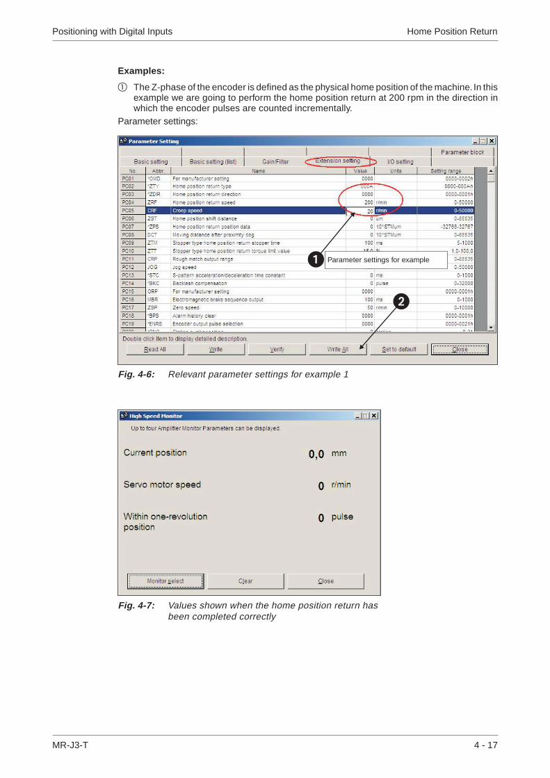
Examples:
� The Z-phase of the encoder is defined as the physical home position of the machine. In thisexample we are going to perform the home position return at 200 rpm in the direction inwhich the encoder pulses are counted incrementally.
Parameter settings:
Positioning with Digital Inputs Home Position Return
MR-J3-T 4 - 17
Fig. 4-6: Relevant parameter settings for example 1
�
� Parameter settings for example
Fig. 4-7: Values shown when the home position return hasbeen completed correctly

� Perform a home position return as in example 1 but with an offset between the physical andencoder home positions, set with parameter PC06.
Parameter settings:
Home Position Return Positioning with Digital Inputs
4 - 18 MITSUBISHI ELECTRIC
Fig. 4-8: Relevant parameter settings for example 2. The offset is entered with param-eter PC06.
�
� Parameter settings for example
Fig. 4-9: Values shown when the home position return has been completed correctly
Following completion of the homeposition return:
The servo motor has travelled tothe specified home position. Thehome position of the encoder hasbeen exceeded by the value ofPC06 = 3,000 µm. For the motorconnected this is equivalent to259,144 encoder pulses.

4.3.2 Dog mode home position return
In this mode, instead of the encoder Z-phase(Fig. 4-6), the DOG signal is used to switch from“home position return speed” PC04 to “creep speed” PC05. You can use parameter PD16 “prox-imity dog detection polarity” to specify whether a logical “1” or a logical “0” should be identified asan active DOG signal.
As in � above, the physical home position can be shifted in relation to the home (zero) positionof the encoder (Z-phase) with PC06 “home position offset (shift)”. In addition to this you can alsoset a non-zero coordinate for the home position with PC07.
Conditions for the proximity dog signal:
The proximity dog signal (DOG) must fulfill the following conditions to ensure that the Z-phase ofthe encoder is detected during the activation period of the DOG signal:
Positioning with Digital Inputs Home Position Return
MR-J3-T 4 - 19
L1 � 60 � 2 L1 = Length of the DOG signal in [mm]V = Home position return speed in [mm/min]td = Deceleration time in [s]
L2 � 2 � �S L2 = Length of the DOG signal in [mm]�S = Distance for one rotation of the motor in [mm]
V td

Timing chart:
Home Position Return Positioning with Digital Inputs
4 - 20 MITSUBISHI ELECTRIC
Auto/Manual mode (MD0) ONOFF
Select point table no. (DI0)
Start commandForward (ST1)
ONOFF
Start commandReverse (ST2)
ONOFF
Servo motor speed setting
Z-phase of encoder ONOFF
DOG signal ONOFF
Home return complete (ZP) ONOFF
Fig. 4-10: Home position return in proximity dog mode
PC05 “Creep speed”
PC04 “Home pos. return speed”
PC06 “Home offset”

� You must turn the power off and on again to activate this parameter.
Example:
In the following example the physical home position is at the position of the Z-phase of theencoder. However, we now want to assign a non-zero value in the physical coordinate system tothis position.
Positioning with Digital Inputs Home Position Return
MR-J3-T 4 - 21
No. Code Function Description
PA05 � *FTY Feed length multi-plication factor
Needed here to scale the home position value to the physical coor-dinate system when a home position offset (shift) has been set.
PC02 � *ZTY Home position re-turn mode
Selects the home position return mode:0: Proximity dog mode (DOG)
PC03 � *ZDIR Home position re-turn direction
0: Incrementing counting of encoder pulses1: Decrementing counting of encoder pulses
PC04 ZRF Home position re-turn speed
Sets home position return speed until first detection of the Z-phasein [rpm].
PC05 CRF Creep speed Speed for precise movement to home position in [rpm]
PC06 ZST Home positionoffset (shift)
Distance between the encoder home position (Z-phase) and thephysical home position in [µm]. Does not change the zero point ofthe physical coordinate system.
PC07 � *ZPS Home position re-turn position value
The home position return stops when the Z-phase position isreached.You can enter a non-zero coordinate for this position [in10STMµm] with this parameter.
PD16 � *DIAB Input signalpolarity
Logical value for detection of the proximity dog signal (DOG):0: Active DOG on logical "0"1: Active DOG on logical "1"
Table 4-2: Parameter reference table
Parameter value Multiplication factor STM
0 1
1 10
2 100
3 1000

Parameter settings:
The position value is calculated as follows:
X = PA05 � PC07 in [mm]
In the above example with PA05 = 1 and PC07 = 1000 [10STM µm] this gives us:
X = 1000 � 101 µm
Home Position Return Positioning with Digital Inputs
4 - 22 MITSUBISHI ELECTRIC
Fig. 4-11: Relevant parameter settings for the example. The home position value is en-tered with PC07.
�
� Parameter settings for example
Fig. 4-12: Values shown when the home position return has been completed correctly
Following completion of thehome position return:
The servo motor has travelled tothe encoder home positionwhich is also the machine’sphysical home position. How-ever, this position correspondsto a value of 100mm in the ma-chine’s coordinate system.

4.4 Configuration for Positioning
If you install the MR-J3-D01 I/O expansion you can use point table positioning, which allows youto select positions from a list of up to 256 table entries with a combination of eight digital inputs.Table 4-3 shows how binary input signals are encoded to address the point table entries.
In the factory default configuration the incremental system is activated, which means that theabsolute position detection system is turned off (PA03 “absolute position detection system”).Inthis mode the current position is not stored when the power is turned off and you must thus per-form a home position return every time the amplifier is powered on. The default configurationalso uses absolute target positions (PA01 “positioning control mode”).
� To activate this parameter you must switch the amplifier power off and on again.
Positioning with Digital Inputs Configuration for Positioning
MR-J3-T 4 - 23
Digital Input Signals Selected PointTable EntryDI7 DI6 DI5 DI4 DI3 DI2 DI1 DI0
0 0 0 0 0 0 0 1 1
0 0 0 0 0 0 1 0 2
0 0 0 0 0 0 1 1 3
0 0 0 0 0 1 0 0 4
···
···
···
···
···
···
···
···
···
1 1 1 1 1 1 1 0 254
1 1 1 1 1 1 1 1 255
Table 4-3: Selection of point table entries with digital input signals
No. Code Function Description
PA01 � *STY Positioning controlmode
0: Absolute target position values1: Incremental target position values
PA03 � *ABS Absolute positiondetection system
0: Incremental system (absolute detection off)1: Absolute position detection system on
PA05 � *FTY Feed length multi-plication factor
Needed here to scale the home position value to the physical coor-dinate system when a home position offset (shift) has been set.
Table 4-4: Parameter reference
Parametervalue
Multiplicationfactor STM
Range of the targetposition values
0 1 −999.999 .. +999.999
1 10 −9999.99 .. +9999.99
2 100 −99999.9 .. +99999.9
3 1000 −999999 .. +999999
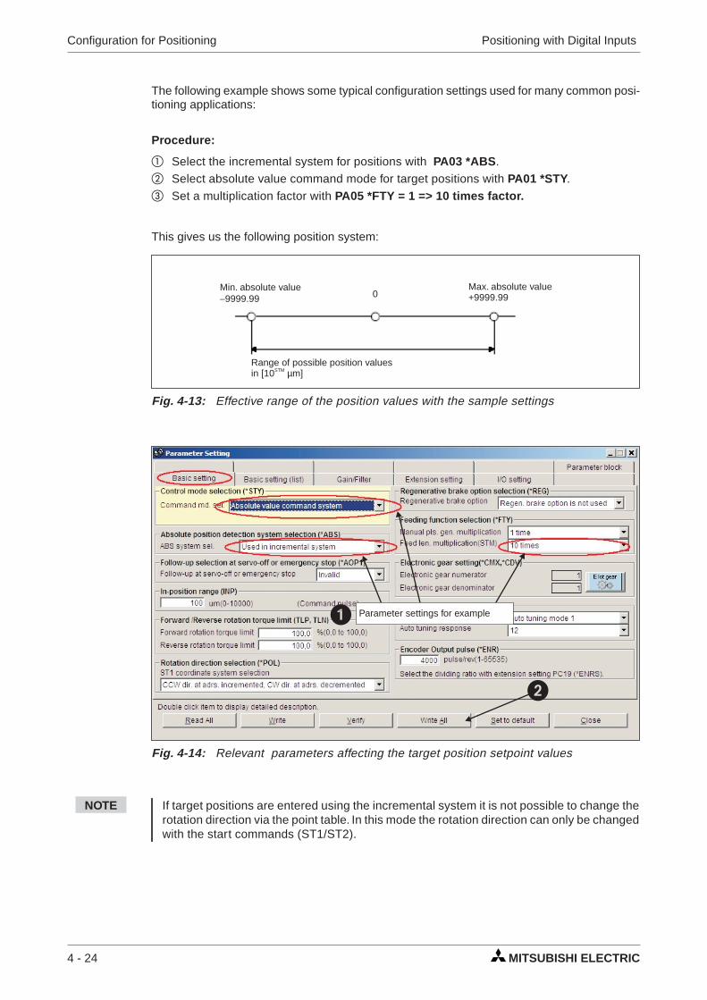
The following example shows some typical configuration settings used for many common posi-tioning applications:
Procedure:
� Select the incremental system for positions with PA03 *ABS.� Select absolute value command mode for target positions with PA01 *STY.� Set a multiplication factor with PA05 *FTY = 1 => 10 times factor.
This gives us the following position system:
NOTE If target positions are entered using the incremental system it is not possible to change therotation direction via the point table. In this mode the rotation direction can only be changedwith the start commands (ST1/ST2).
Configuration for Positioning Positioning with Digital Inputs
4 - 24 MITSUBISHI ELECTRIC
Fig. 4-13: Effective range of the position values with the sample settings
Min. absolute value−9999.99
Max. absolute value+9999.990
Range of possible position valuesin [10STM µm]
Fig. 4-14: Relevant parameters affecting the target position setpoint values
�
� Parameter settings for example
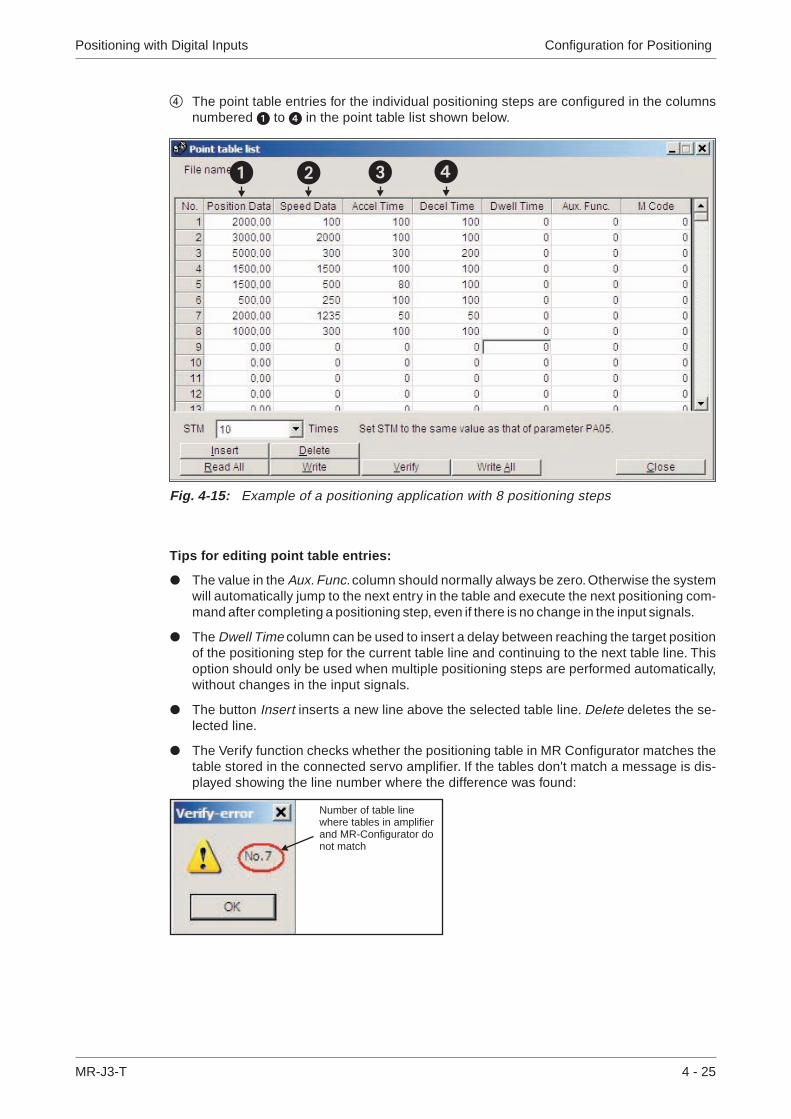
� The point table entries for the individual positioning steps are configured in the columnsnumbered � to � in the point table list shown below.
Tips for editing point table entries:
� The value in the Aux. Func. column should normally always be zero. Otherwise the systemwill automatically jump to the next entry in the table and execute the next positioning com-mand after completing a positioning step, even if there is no change in the input signals.
� The Dwell Time column can be used to insert a delay between reaching the target positionof the positioning step for the current table line and continuing to the next table line. Thisoption should only be used when multiple positioning steps are performed automatically,without changes in the input signals.
� The button Insert inserts a new line above the selected table line. Delete deletes the se-lected line.
� The Verify function checks whether the positioning table in MR Configurator matches thetable stored in the connected servo amplifier. If the tables don't match a message is dis-played showing the line number where the difference was found:
Positioning with Digital Inputs Configuration for Positioning
MR-J3-T 4 - 25
Fig. 4-15: Example of a positioning application with 8 positioning steps
� � � �
Number of table linewhere tables in amplifierand MR-Configurator donot match
� Always deactivate start command ST1/ST2 before starting a new positioning sequence.Then you can select a new table entry with DI0 - DI7 and start the positioning sequencewith ST1/ST2.
� Table entries are not reset when you restore the amplifier's factory default settings!
� You do not need to turn the amplifier off and on again after changing table entries.
NOTE Please see the instruction manual for full details on all these procedures.
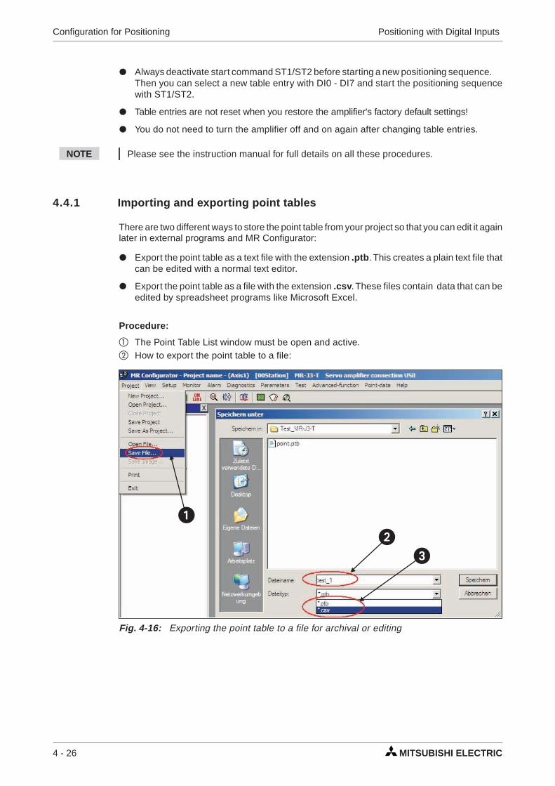
4.4.1 Importing and exporting point tables
There are two different ways to store the point table from your project so that you can edit it againlater in external programs and MR Configurator:
� Export the point table as a text file with the extension .ptb. This creates a plain text file thatcan be edited with a normal text editor.
� Export the point table as a file with the extension .csv. These files contain data that can beedited by spreadsheet programs like Microsoft Excel.
Procedure:
� The Point Table List window must be open and active.� How to export the point table to a file:
Configuration for Positioning Positioning with Digital Inputs
4 - 26 MITSUBISHI ELECTRIC
Fig. 4-16: Exporting the point table to a file for archival or editing
��
�

� How to open/import a point table data file:
Positioning with Digital Inputs Configuration for Positioning
MR-J3-T 4 - 27
Fig. 4-17: Opening a point table file to import the data
�
�
Fig. 4-18: Point table position data imported from a .csv file

4.5 Functional Test of Digital Input Positioning
Normally you need a simple controller to set the digital inputs used to select the point table posi-tion entries, for example a PC, a mini PLC or an HMI control terminal. This chapter explains howyou can perform a thorough check of the functionality of the positioning control functions withoutneeding to perform the additional work of programming and installing a controller.
Fig. 4-19 shows a test installation without an external controller. Note that the FX Simulation Boxused in this setup can set a maximum of 14 digital inputs.
NOTE The test setup shown above does not use any safety features for the tests (EMG. OFF). Youshould thus only use this setup in a controlled test environment where errors cannot causeany danger for personnel or equipment!
Functional Test of Digital Input Positioning Positioning with Digital Inputs
4 - 28 MITSUBISHI ELECTRIC
Fig. 4-19: Test setup for simulating positioning with digital inputs
1-phase200–230V AC
Servo motor
PC
FX Simulation Box
24V DC24V DCpower supply
Motor
EncoderEncoder cable
� MR-J3USBCBL3MCable length: 3m
� MR-J2CMP2
� MR-J2M-CNT1TBL-MCable length: 0.5–1m
� MR-TB50
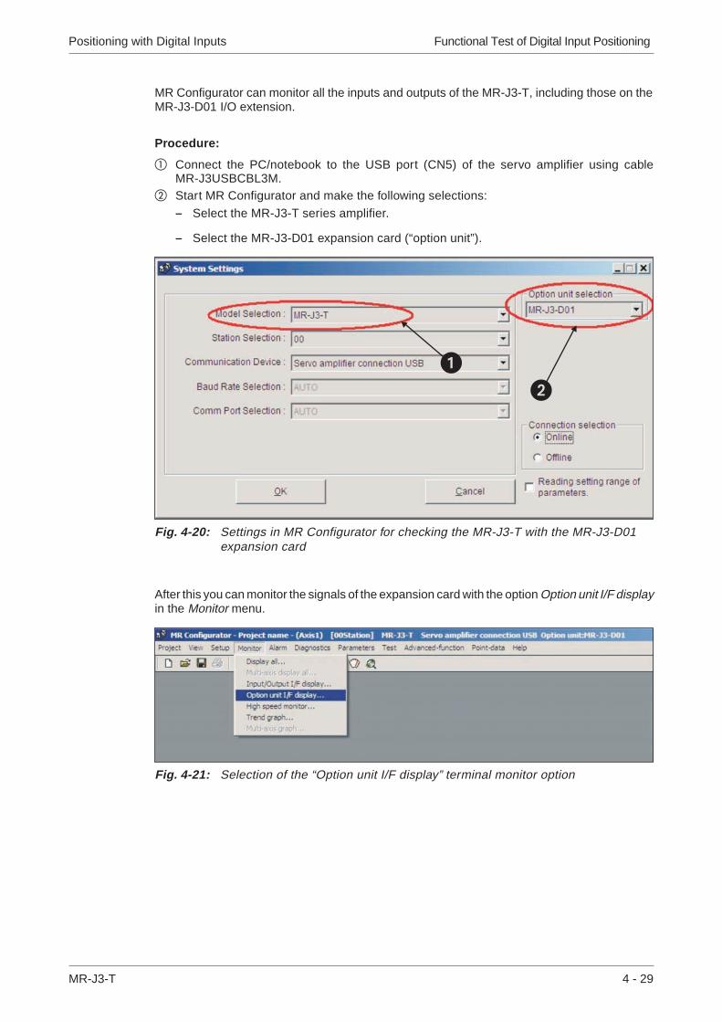
MR Configurator can monitor all the inputs and outputs of the MR-J3-T, including those on theMR-J3-D01 I/O extension.
Procedure:
� Connect the PC/notebook to the USB port (CN5) of the servo amplifier using cableMR-J3USBCBL3M.
� Start MR Configurator and make the following selections:
– Select the MR-J3-T series amplifier.
– Select the MR-J3-D01 expansion card (“option unit”).
After this you can monitor the signals of the expansion card with the option Option unit I/F displayin the Monitor menu.
Positioning with Digital Inputs Functional Test of Digital Input Positioning
MR-J3-T 4 - 29
Fig. 4-20: Settings in MR Configurator for checking the MR-J3-T with the MR-J3-D01expansion card
Fig. 4-21: Selection of the “Option unit I/F display” terminal monitor option
��

Functional Test of Digital Input Positioning Positioning with Digital Inputs
4 - 30 MITSUBISHI ELECTRIC
Fig. 4-22: The “Option unit I/F display” terminal monitoring window

5 Positioning via a CC-Link Network
As an alternative to using digital signals you can also control positioning with MR-J3-T servoamplifiers via a CC-Link network connection.
NOTE Before proceeding ensure that the MR-J3-D01I/O expansion card is not installed. If it is in-stalled CC-Link communications will be disabled.
5.1 Additional Connections
In addition to the minimum configuration described in chapter 3.1 you also need to connect theCC-Link cable and the cabling for connector CN6 for this mode.
Positioning via a CC-Link Network Additional Connections
MR-J3-T 5 - 31
Fig. 5-1: Connections for operating the servo amplifier via a CC-Link network
1-phase200–230V AC
Servo motor
Motor
EncoderEncoder cable
Alarm
EMG. OFF OFF ON
EMG. OFF
Servo ON
Servo amplifier
24V DC24V DC ±10%800mA
24V DC24V DC ±10%150mA
CC-Linkmodule
CC-Link cableV1.10 compatible
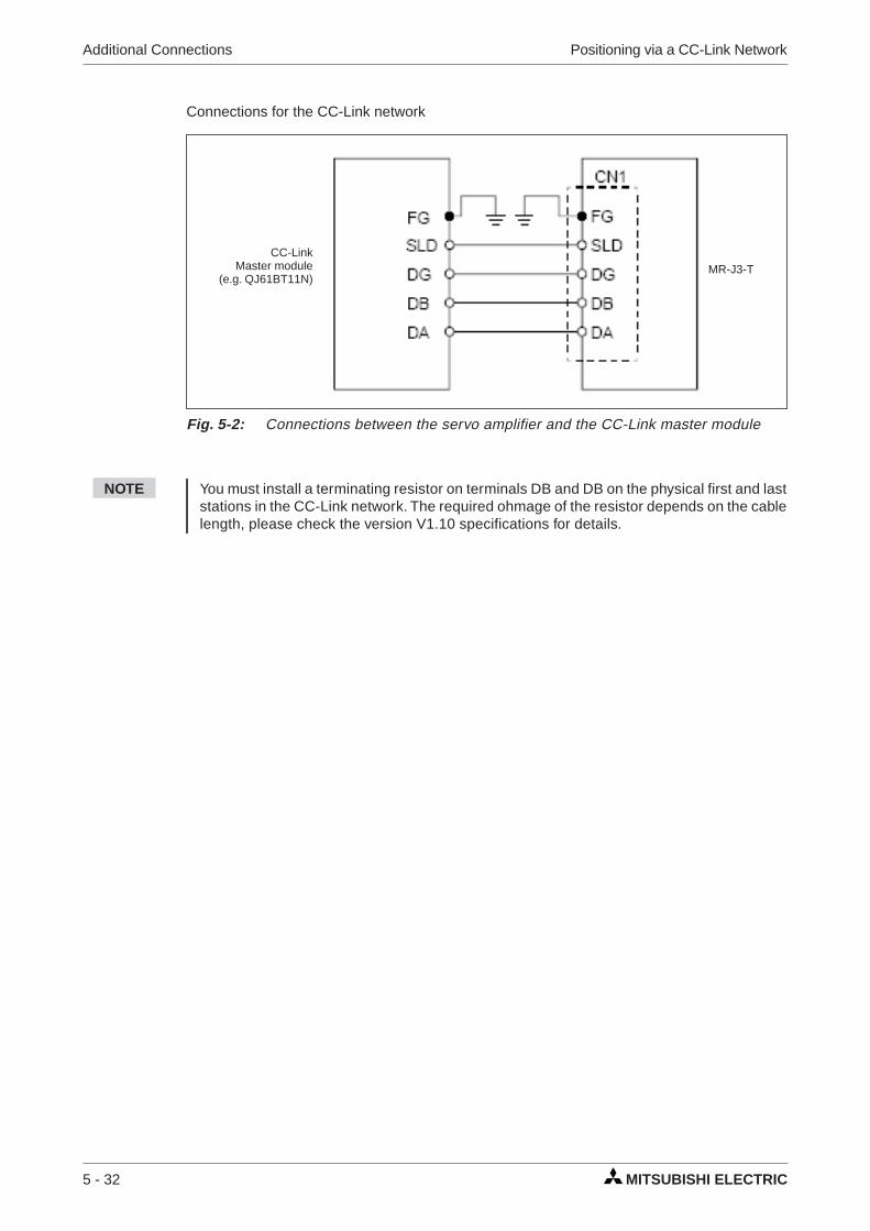
Connections for the CC-Link network
NOTE You must install a terminating resistor on terminals DB and DB on the physical first and laststations in the CC-Link network. The required ohmage of the resistor depends on the cablelength, please check the version V1.10 specifications for details.
Additional Connections Positioning via a CC-Link Network
5 - 32 MITSUBISHI ELECTRIC
Fig. 5-2: Connections between the servo amplifier and the CC-Link master module
CC-LinkMaster module
(e.g. QJ61BT11N)MR-J3-T

5.2 CC-Link Communication Settings
5.2.1 Settings on the servo amplifier
In the instructions below we are assuming that you have an operating CC-Link network with thefollowing specifications:
� Data rate 156Kbit/s
� The master station is a QJ61BT11N module that is integrated in a System Q con-troller platform with a Q02H-CPU.
Procedure:
� Set the number of reserved stations:
� Set the station address (max. value 64):
Positioning via a CC-Link Network CC-Link Communication Settings
MR-J3-T 5 - 33
Fig. 5-3: Correct position of switch S1 for setting the number of reserved stations
S1
Factory defaultsetting
1 reserved station
2 reserved stations
Fig. 5-4: Set switches x1 and x10 to the correct station address
higher values
lower values
address digits
x1 x10

� Set the data rate:
NOTE The servo amplifier settings required for point table positioning are described in chapters 4.2through 4.4.Please check that these settings have been made correctly before proceeding.
CC-Link Communication Settings Positioning via a CC-Link Network
5 - 34 MITSUBISHI ELECTRIC
Fig. 5-5: Mode switch setting for the network data rate
Mode Baud rate

5.2.2 Configuration for communication with GX IEC Developer
Generally, positioning control is performed via a CC-Link network in applications where an addi-tional PLC system is used for automation tasks as well as the integrated controller in the ampli-fier. In this example we will thus only provide detailed descriptions of the settings required tointegrate the servo amplifier in your project.
Procedure:
How to open an existing project in GX IEC Developer:
� Select Network � in the project directory tree in the left window.� Select CC-Link � in the Network Parameter box.� This opens the window Network parameters: Setting the CC-Link list where you can now
enter the settings shown in Fig. 5-6 �.
Positioning via a CC-Link Network CC-Link Communication Settings
MR-J3-T 5 - 35
Fig. 5-6: Settings required in GX IEC Developer for CC-Link communication betweenthe controller and the servo amplifier
�
�
�
(a)
(b)
(c)

Notes on the network settings:
(a) In the example only one servo amplifier is connected to the CC-Link network. This value mustbe increased by the number of slave stations installed if applicable.
(b) These values specify which bits or data words are to be used to control the servo amplifier.The settings shown in the example are for the following assignments:
(c) Slave station type setting:
� Connect the PC to the PLC and transfer the modified project to the controller.
NOTE If the CC-Link connection to the servo amplifier is established successfully the L.RUN, SDund RD status LEDs on the servo amplifier will light up.
CC-Link Communication Settings Positioning via a CC-Link Network
5 - 36 MITSUBISHI ELECTRIC
Fig. 5-7: This configuration also enables exchange of data words
PLC -> Servo Amplifier Servo Amplifier -> PLC
PLC I/Os Registers Signals PLC I/Os Registers Signals
Y100 RYn0 SON X100 RXn0 RD
Y101 RYn1 ST1 X101 RXn1 INP
Y102 RYn2 ST2 X103 RXn3 ZP
Y103 RYn3 DOG X11A RX(n+1)A ALM
Y104 RYn4 LSP
Y105 RYn5 LSN
NOTE:
Signals DI5, DI6 and DI7 are only availablewhen the amplifier is configured to occupy 2stations in the network.
Y106 RYn6 MD0
Y10A RYnA DI0
Y10B RYnB DI1
Y10C RYnC DI2
Y10D RYnD DI3
Y10E RYnE DI4
Y10F RYnF RES
Table 5-1: Signal assignments

5.3 Testing the Servo Amplifier via CC-Link
Before proceeding it is a good idea use the monitoring function in GX IEX Developer to checkthat the individual servo functions can be started correctly (e.g. return to home, positioning).After this you can then test the correct operation of the servo system with the PLC program.
Procedure:
� Activate monitoring mode.� Select Entry Data Monitor in the Online menu.� Enter the individual remote I/Os to be set or monitored.
Positioning via a CC-Link Network Testing the Servo Amplifier via CC-Link
MR-J3-T 5 - 37
Fig. 5-8: The Entry Data Monitor window where you can set remote I/Os to test theservo functions
�

A Appendix
A.1 Digital Signals Quick Reference
Appendix Digital Signals − Quick Reference
MR-J3-T A - 39
ConnectorPins
Signal CodesDescription DI /
DODI/DO CC-Link
CN6-1 EMG – Forced stop - emergency safety signal:The signal is permanently assigned to this pin and must be acti-vated for motor control.
DI
CN6-2 DOG RYn3 Proximity dog switch:This signal is used for some of the home position return modes.(See chapter 4.3)
DI
CN6-3 LSP RYn4 Forward rotation stroke end switch DI
CN6-4 LSN RYn5 Reverse rotation stroke end switch DI
CN6-14 RD RXn0 Servo amplifier ready DO
CN6-15 ALM RX(n+1)A Alarm, signals a servo error DO
CN6-16 ZP RXn3 Home position return completed successfully DO
CN10-1 DI0 RYnA Select point table entry, i.e. activate a line in the table for position-ing. Combinations of signals DI0 through DI7 (see Table 4-3) canbe used to selec up tot 256 positioning steps.
NOTE:Signals DI5, DI6 and DI7 are only available when the amplifier oc-cupies 2 stations in the network, thus making 64 bits available viaCC-Link.
DI
Point table entry no.1
CN10-2 DI1 RYnB DI
Point table entry no. 2
CN10-3 DI2 RYnC DI
Point table entry no. 3
CN10-4 DI3 RYnD DI
Point table entry no. 4
CN10-5 DI4 RYnE DI
Point table entry no. 5
CN10-6 DI5 RY(n+2)3 DI
Point table entry no. 6
CN10-7 DI6 RY(n+2)4 DI
Point table entry no. 7
CN10-8 DI7 RY(n+2)5 DI
Point table entry no. 8
CN10-13 DICOM – Connection for an external power supply for the digital control termi-nals. Negative connection for source interface logic (PNP).
DI
CN10-14
CN10-21 SON RYn0 SERVO ON:Activating the SON signal powers on the base circuit and makesthe amplifier ready for operation.
DI
CN10-22 ACD0 – Digital output signals for encoded error messages (see AppendixA.3)
DO
CN10-23 ACD1 –
CN10-24 ACD2 –
CN10-25 ACD3 –
CN10-26 RES RY1A Reset for error messages DI
CN10-32 MD0 RYn6 Switch between automatic/manual mode:The MD0 signal must be off for opertion in jog mode. The signalmust be activated before starting a home position return or position-ing.
DI
CN10-35 ST1 RYn1 Start signal for forward rotation DI
CN10-36 ST2 RYn2 Start signal for reverse rotation DI
CN10-37 DOCO – Connection for an external power supply for the digital control termi-nals. Positive connection for source interface logic (PNP).
DI
CN10-49 INP RXn1 IN Position: Target position reached signal. DO
Table A-1: Digital signals - quick reference

A.2 Standard Parameters Quick Reference
� To activate this parameter you must switch the amplifier power off and on again.
Standard Parameters − Quick Reference Appendix
A - 40 MITSUBISHI ELECTRIC
No. Code Function Description
PA01 � *STY Positioning controlmode
0: Absolute value command system for target positions1: Incremental value command system for target positions
PA03 � *ABS Absolute positiondetection system
0: Incremental system (absolute position detection off)1: Absolute position detection system on
PA05 � *FTY Feed length multipli-cation factor
Needed here to scale the home position value to the physical co-ordinate system when a home position offset (shift) has been set.
PA14 � *POL Servo motor rotationdirection
Motor rotation direction (looking at shaft end facing motor):0: Anticlockwise when ST1 signal is active1: Clockwise when ST1 signal is active
PC02 � *ZTY Home position re-turn mode
Selects mode to be used for home position return:0: Proximity dog mode
PC03 � *ZDIR Home position re-turn direction
0: Incrementing counting of encoder pulses1: Decrementing counting of encoder pulses
PC04 ZRF Home position re-turn speed
Sets home position return speed until first detection of theZ-phase in [rpm].
PC05 CRF Creep speed Speed for precise movement to home position in [rpm]
PC06 ZST Home positionoffset (shift)
Distance between the encoder home position (Z-phase) and thephysical home position in [µm]. Does not change the zero point ofthe physical coordinate system.
PC07 � *ZPS Home position re-turn position value
The home position return stops when the Z-phase position isreached.You can enter a non-zero coordinate for this position [in10STMµm] with this parameter.
PD01 � *DIA1 Automatic activationof input signals
This parameter configures the amplifier to automatically set thedigital signals internally to a logical "1" when the power isswitched on.
PD01 � *DIAB Polarity of the inputsignal
Logical value for detection of the proximity dog signal (DOG):0: Active DOG on logical "0"1: Active DOG on logical "1"
Table A-2: Standard parameters quick reference
Parametervalue
Multiplicationfactor STM
Range of the targetposition values
0 1 −999.999 ... +999.999
1 10 −9999.99 ... +9999.99
2 100 −99999.9 ... +99999.9

A.3 Alarms and Warning Messages
Appendix Alarms and Warning Messages
MR-J3-T A - 41
Display
Alarm Code
Error
Alarm Reset
ACD3(Bit 3)
ACD2(Bit 2)
ACD1(Bit 1)
ACD0(Bit 0)
PowerSupply
OFF ON
MR-Configurator/
HMI
Reset(RES)
Ala
rme
A10 0 0 1 0 Undervoltage ✔ ✔ ✔
A12 0 0 0 0 Memory error 1 ✔ — —
A13 0 0 0 0 Clock error ✔ — —
A15 0 0 0 0 Memory error 2(E²PROM) ✔ — —
A16 0 1 1 0 Encoder error 1(at power on) ✔ — —
A17 0 0 0 0 Board error ✔ — —
A19 0 0 0 0 Memory error 2(Flash ROM) ✔ — —
A1A 0 1 1 0 Incorrect servomotor ✔ — —
A20 0 1 1 0 Encoder error 2 ✔ — —
A24 1 1 0 0 Main circuit error ✔ ✔ ✔
A25 1 1 1 0 Absolute positionlost/erased ✔ — —
A30 0 0 0 1 Regenerativebraking overload ✔ � ✔ � ✔ �
A31 0 1 0 1 Overspeed ✔ ✔ ✔
A32 0 1 0 0 Overcurrent ✔ — —
A33 1 0 0 1 Overvoltage ✔ ✔ ✔
A35 1 1 0 1 Input frequencytoo high ✔ — —
A37 1 0 0 0 Parameter error ✔ — —
A45 0 0 1 1 Main circuitoverheat ✔ � ✔ � ✔ �
A46 0 0 1 1 Servo motoroverheat ✔ � ✔ � ✔ �
A47 0 0 1 1 Cooling fan error ✔ — —
A50 0 0 1 1 Overload 1 ✔ � ✔ � ✔ �
A51 0 0 1 1 Overload 2 ✔ � ✔ � ✔ �
Table A-3: Error messages(1)
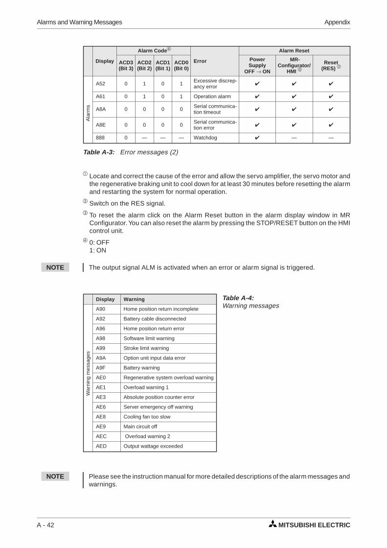
� Locate and correct the cause of the error and allow the servo amplifier, the servo motor andthe regenerative braking unit to cool down for at least 30 minutes before resetting the alarmand restarting the system for normal operation.
� Switch on the RES signal.� To reset the alarm click on the Alarm Reset button in the alarm display window in MR
Configurator. You can also reset the alarm by pressing the STOP/RESET button on the HMIcontrol unit.
� 0: OFF1: ON
NOTE The output signal ALM is activated when an error or alarm signal is triggered.
NOTE Please see the instruction manual for more detailed descriptions of the alarm messages andwarnings.
Alarms and Warning Messages Appendix
A - 42 MITSUBISHI ELECTRIC
Display Warning
War
ning
mes
sage
s
A90 Home position return incomplete
A92 Battery cable disconnected
A96 Home position return error
A98 Software limit warning
A99 Stroke limit warning
A9A Option unit input data error
A9F Battery warning
AE0 Regenerative system overload warning
AE1 Overload warning 1
AE3 Absolute position counter error
AE6 Server emergency off warning
AE8 Cooling fan too slow
AE9 Main circuit off
AEC Overload warning 2
AED Output wattage exceeded
Table A-4:Warning messages
Display
Alarm Code
Error
Alarm Reset
ACD3(Bit 3)
ACD2(Bit 2)
ACD1(Bit 1)
ACD0(Bit 0)
PowerSupply
OFF ON
MR-Configurator/
HMI
Reset(RES)
Ala
rms
A52 0 1 0 1 Excessive discrep-ancy error ✔ ✔ ✔
A61 0 1 0 1 Operation alarm ✔ ✔ ✔
A8A 0 0 0 0 Serial communica-tion timeout ✔ ✔ ✔
A8E 0 0 0 0 Serial communica-tion error ✔ ✔ ✔
888 0 — — — Watchdog ✔ — —
Table A-3: Error messages (2)
Index
MR-J3-T A - 43
Index
AAlarm messages
List . . . . . . . . . . . . . . . . . . . . A - 41
Automatic input signal activation
Turning off . . . . . . . . . . . . . . . . . 4 - 14
CCC-Link communications
Settings . . . . . . . . . . . . . . . . . . 5 - 33
Connections
Minimum connections . . . . . . . . . . . 3 - 5
Creep speed . . . . . . . . . . . . . . . . . 4 - 15
DDigital signals
Quick reference . . . . . . . . . . . . . . A - 39
DOG home position return . . . . . . . . . . 4 - 19
EExpansion card MR-J3-D01
Installation . . . . . . . . . . . . . . . . . 2 - 3
Settings . . . . . . . . . . . . . . . . . . 4 - 23
FFunctional test . . . . . . . . . . . . . . . . . 3 - 5
CC-Link . . . . . . . . . . . . . . . . . . 5 - 37
Positioning with digital inputs . . . . . . . 4 - 28
Settings . . . . . . . . . . . . . . . . . . . 3 - 7
GGX IEC Developer
Data communications . . . . . . .5 - 35, 5 - 37
HHome position return . . . . . . . . . . . . . 4 - 15
IInstallation
Hardware . . . . . . . . . . . . . . . . . . 2 - 3
MMinimum connections . . . . . . . . . . . . . 3 - 5
MR Configurator
functional check . . . . . . . . . . . . . . 3 - 10
PParameter
Quick reference . . . . . . . . . . . . . . 4 - 21
Pin assignments . . . . . . . . . . . . . . . . 3 - 6
Point table
configuring . . . . . . . . . . . . . . . . . 3 - 9
Point table positioning . . . . . . . . . . . . 4 - 11
Preparations . . . . . . . . . . . . . . . . 1 - 1
Positioning
Settings . . . . . . . . . . . . . . . . . . 4 - 23
via a CC-Link network. . . . . . . . . . . 5 - 31
with digital inputs . . . . . . . . . . . . . 4 - 11
Positioning table
exporting . . . . . . . . . . . . . . . . . 4 - 26
importing . . . . . . . . . . . . . . . . . 4 - 26
Positioning table entries
selecting. . . . . . . . . . . . . . . . . . 3 - 10
SServo amplifier
selecting . . . . . . . . . . . . . . . . . . 3 - 7
Signal assignments
Connectors CN6 and CN10 . . . . . . . . 4 - 12
Standard parameters
Quick reference . . . . . . . . . . . . . . A - 40
WWarning messages
Reference list . . . . . . . . . . . . . . . A - 42
ZZ-phase reference
without DOG signal . . . . . . . . . . . . 4 - 15

MITSUBISHI ELECTRIC
MITSUBISHIELECTRIC
FACTORY AUTOMATIONMitsubishi Electric Europe B.V. /// FA - European Business Group /// Gothaer Straße 8 /// D-40880 Ratingen /// GermanyTel.: +49(0)2102-4860 /// Fax: +49(0)2102-4861120 /// [email protected] /// www.mitsubishi-automation.com
Specifications subject to change /// Art. no. XXXXXX-A /// 12.2007
HEADQUARTERS
MITSUBISHI ELECTRIC EUROPE B.V.German BranchGothaer Straße 8
Phone: +49 (0)2102 / 486-0Fax: +49 (0)2102 / 486-1120MITSUBISHI ELECTRIC EUROPE B.V.French Branch25, Boulevard des Bouvets
Phone: +33 (0)1 / 55 68 55 68Fax: +33 (0)1 / 55 68 57 57MITSUBISHI ELECTRIC EUROPE B.V.Irish BranchWestgate Business Park, Ballymount
Phone: +353 (0)1 4198800Fax: +353 (0)1 4198890MITSUBISHI ELECTRIC EUROPE B.V.Italian BranchViale Colleoni 7
Phone: +39 039 / 60 53 1Fax: +39 039 / 60 53 312MITSUBISHI ELECTRIC CORPORATIONOffice Tower “Z” 14 F
Tokyo 104-6212Phone: +81 3 622 160 60Fax: +81 3 622 160 75MITSUBISHI ELECTRIC EUROPE B.V.UK BranchTravellers Lane
Phone: +44 (0)1707 / 27 61 00Fax: +44 (0)1707 / 27 86 95MITSUBISHI ELECTRIC EUROPE B.V.Spanish BranchCarretera de Rubí 76-80
Phone: +34 93 / 565 3131Fax: +34 93 / 589 1579
USAMITSUBISHI ELECTRIC AUTOMATION500 Corporate Woods Parkway
Phone: +1 847 478 21 00Fax: +1 847 478 22 83
EUROPEAN REPRESENTATIVES
GEVAWiener Straße 89
Phone: +43 (0)2252 / 85 55 20Fax: +43 (0)2252 / 488 60TEHNIKONOktyabrskaya 16/5, Off. 703-711
Phone: +375 (0)17 / 210 46 26Fax: +375 (0)17 / 210 46 26Koning & Hartman B.V.Industrial SolutionsWoluwelaan 31
Phone: +32 (0)2 / 257 02 40Fax: +32 (0)2 / 257 02 49AKHNATON4 Andrej Ljapchev Blvd. Pb 21
Phone: +359 (0)2 / 97 44 05 8Fax: +359 (0)2 / 97 44 06 1INEA CR d.o.o.Losinjska 4 a
Phone: +385 (0)1 / 36 940 - 01/ -02/ -03Fax: +385 (0)1 / 36 940 - 03AutoCont Control Systems, s.r.o.Jelinkova 59/3
Phone: +420 (0)59 / 5691 150Fax: +420 (0)59 / 5691 199AutoCont Control Systems, s.r.o.Technologická 374/6
Phone: +420 595 691 150Fax: +420 595 691 199B:TECH, a.s.Na Ostrove 84
Phone: +420 (0)569 / 408 841Fax: +420 (0)569 / 408 889B:TECH, a.s.HeadofficeU Borové 69
Phone: +420 569 777 777Fax: +420 569 777 778Beijer Electronics A/SLautruphoj 1-3
Phone: +45 (0)70 / 26 46 46Fax: +45 (0)70 / 26 48 48Beijer Electronics Eesti OÜPärnu mnt.160i
Phone: +372 (0)6 / 51 81 40Fax: +372 (0)6 / 51 81 49Beijer Electronics OYJaakonkatu 2
Phone: +358 (0)207 / 463 500Fax: +358 (0)207 / 463 501UTECO A.B.E.E.5, Mavrogenous Str.
Phone: +30 211 / 1206 900Fax: +30 211 / 1206 999MELTRADE Ltd.Fertő utca 14.
Phone: +36 (0)1 / 431-9726Fax: +36 (0)1 / 431-9727
EUROPEAN REPRESENTATIVES
Beijer Electronics SIAVestienas iela 2
Phone: +371 (0)784 / 2280Fax: +371 (0)784 / 2281Beijer Electronics UABSavanoriu Pr. 187
Phone: +370 (0)5 / 232 3101Fax: +370 (0)5 / 232 2980INTEHSIS srlbld. Traian 23/1
Phone: +373 (0)22 / 66 4242Fax: +373 (0)22 / 66 4280Beijer Electronics ASPostboks 487
Phone: +47 (0)32 / 24 30 00Fax: +47 (0)32 / 84 85 77Koning & Hartman B.V.Haarlerbergweg 21-23
Phone: +31 (0)20 / 587 76 00Fax: +31 (0)20 / 587 76 05MPL Technology Sp. z o.o.Ul. Krakowska 50
Phone: +48 (0)12 / 630 47 00Fax: +48 (0)12 / 630 47 01Sirius Trading & Services srlAleea Lacul Morii Nr. 3
Phone: +40 (0)21 / 430 40 06Fax: +40 (0)21 / 430 40 02CRAFT Consulting & Engineering d.o.o.Toplicina str.4 lok 6
Phone: +381 (0)18 / 292-24-4/5 , 523 962Fax: +381 (0)18 / 292-24-4/5 , 523 962INEA SR d.o.o.Karadjordjeva 12/260
Phone: +381 (0)26 / 617 163Fax: +381 (0)26 / 617 163CS MTrade Slovensko, s.r.o.Vajanskeho 58
Phone: +421 (0)33 / 7742 760Fax: +421 (0)33 / 7735 144INEA d.o.o.Stegne 11
Phone: +386 (0)1 / 513 8100Fax: +386 (0)1 / 513 8170Beijer Electronics Automation ABBox 426
Phone: +46 (0)40 / 35 86 00Fax: +46 (0)40 / 35 86 02ECONOTEC AGHinterdorfstr. 12
Phone: +41 (0)44 / 838 48 11Fax: +41 (0)44 / 838 48 12GTSDarulaceze Cad. No. 43 KAT. 2
Phone: +90 (0)212 / 320 1640Fax: +90 (0)212 / 320 1649CSC Automation Ltd.15, M. Raskova St., Fl. 10, Office 1010
Phone: +380 (0)44 / 494 33 55Fax: +380 (0)44 / 494-33-66
EURASIAN REPRESENTATIVES
Kazpromautomatics Ltd.2, Scladskaya str.
Phone: +7 3212 / 50 11 50Fax: +7 3212 / 50 11 50AVTOMATIKA SEVERLva Tolstogo str. 7, off. 311
Phone: +7 812 / 718 3238Fax: +7 812 / 718 3239CONSYSPromyshlennaya st. 42
Phone: +7 812 / 325 36 53Fax: +7 812 / 325 36 53Electrotechnical Systems SiberiaDerbenevskaya st. 11A, Office 69
Phone: +7 495 / 744 55 54Fax: +7 495 / 744 55 54STC DRIVE TECHNIQUEPoslannikov per. 9, str 1
Phone: +7 495 / 790 72 10Fax: +7 495 / 790 72 12
MIDDLE EASTREPRESENTATIVE
Sherf Motion Techn. Ltd.Rehov Hamerkava 19
Phone: +972 (0)3 / 559 54 62Fax: +972 (0)3 / 556 01 82
AFRICAN REPRESENTATIVE
CBI Ltd.Private Bag 2016
Phone: + 27 (0)11 / 928 2000Fax: + 27 (0)11 / 392 2354