mr singleshot's book of rifle plans part4
TRANSCRIPT
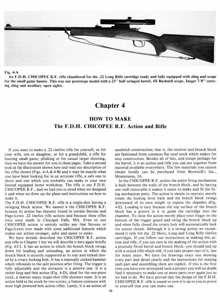
Fig. 4-AAn F.D.H. CHICOPEE R.F. rif le chambered for the .22Long Rifle cartridge ready and fully equipped with sling and scope
for the small game hunter. This was our prototype model with a 23" half octagon barrel, 4X Bushnell scope, Jaeger 7 /E" casty-ing sling and auxil iary open sights.
Chapter 4
HOW TO MAKEThe F.D.H. CHICOPEE R.F. Action and Rifle
If you want to make a .22rimfire rifle for yourself, or foryour wife, son or daughter, or for a grandchild, a rifle forhunting small game, plinking or for casual target shooting,then we have the answer for you in these pages. Take a secondlook at the illustration shown here and read our description ofthe rifles shown (Figs. 4-A & 4-B) and it may be exactly whatyou have been looking for in an accurate rifle, a safe one toshoot and one which you probably can make in your ownlimited equipped home workshop. The rifle is our F.D.H.CHICOPEE R.F., and we had you in mind when we designedit and when we drew up the plans and instructions on how tomake it.The F.D.H. CHICOPEE R.F. rifle is a single-shot having aswinging block action. We named it the CHICOPEE R.F.because its action has features found in certain Stevens andPage-Lewis .22 rimfire rifle actions and because these rifleswere once made in Chicopee Falls, MA. Even so ourCHICOPEE action is entirely unlike any that Stevens orPage-Lewis ever made with some additional features whichmakes our action stronger, safer and easier to make.
We have already described the CHICOPEE R.F. actionand rifle in Chapter I but we will describe it here again briefly(Fig. a-C). It has an action in which the breech block swingsdown for loading and unloading, an action in which thebreech block is securely supported at its rear and locked clos-ed by a rotary locking bolt. It has a manually cocked hammerwhich rebounds to the safe position after firing. The trigger isfully adjustable and the extractor is a postive one. It is arather long and thin action (Fig. 4-D), ideal for the one-piecestock, a feature many single-shot rifle shooters want. It is anaction held in the stock by two screws, a feature common withmost high powered bolt action rifles. Lastly, it is an action of
sandwich construction; that is, the receiver and breech blockare fashioned from common flat steel stock which makes foreasy construction. Besides all of this, and except perhaps forthe barrel, it is an action and rifle you can put together frommaterial available everywhere. The few materials you cannotobtain locally can be purchased from Brownell 's Inc.,Montezuma, IA.
In the CHICOPEE R.F. action the entire fir ing mechanismis built between the walls of the breech block, and by havingone wall removable it makes it easier to make and fit the fir-ing mechanism parts. The action is simple to operate; merelyrotate the locking lever back and the breech block swingsdownward of its own weight to expose the chamber (Fig.4-E). Loading is easy because the top surface of the breechblock has a groove in it to guide the cartridge into thechamber. To close the action merely place your finger on thebottom of the trigger guard and swing the breech block upand when fully closed the rotary lock wil l automatically lockthe action closed. Although it is a strong action we recom-mend it only for the.22 Short, Long and Long Rifle rimfirecartridges. If you follow our instructions in making this ac-tion and rif le, if you use care in the making of the action witha precisely fitted barrel and breech block, you should end upwith a sound rif le which wil l, i f you take proper care of it, lastfor many years. We have the drawings exact size showingevery part and detail clearly and the instructions for makingeach part and assembling them are explicit. If this is the firstt ime you have ever attempted such a project you wil l no doubtfind it necessary to make one or more parts over again just aswe had to do. We have proved that the design of the F.D.H.CHICOPEE R.F. rif le is sound so now it is up to you to proveto yourself that you can make one.
54
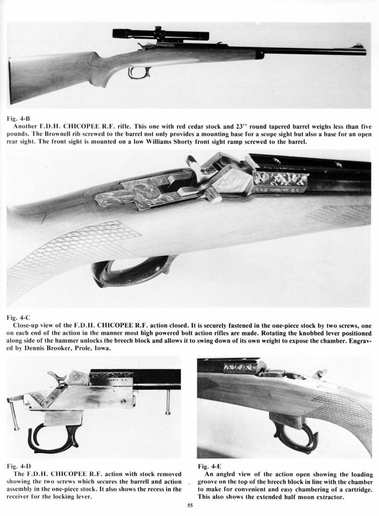
I ig . 4-BAnothcr l ' .D.H. CHICOPEE R.F. rif le. This one with red cedar stock and 23" round tapered barrel weighs less than five
pounds. The Brownell rib screwed to the barrel not only provides a mounting base for a scope sight but also a base for an openrear sight. The front sight is mounted on a low Will iams Shorty front sight ramp screwed to the barrel.
.*rfi!q-*.
Fig. 4-CClose-up view of the F.D.H. CHICOPEE R.F. action closed. It is securely fastened in the one-piece stock by two screws, one
on each end of the action in the manner most high powered bolt action rif les are made. Rotating the knobbed lever positionedalong side of the hammer unlocks the breech block and allows it to swing down of its own weight to expose the chamber. Engrav-ed bv Dennis Brooker. Prole. Iowa.
t ig. 4-I)The I .D.H. CHTCOPEE R.F. act ion wi th s tock removcd
showing the two screws which secures the barrcll and actionassembll in the one-piece stock. It also shows the recess in thereceiver for the locking lcver.
Fig. 4-EAn angled view of the action opcn showing the loading
groove on the top of the breech block in l ine with. the chamberto make for convcnient and easy chambering of a cartridge.This also shows the cxtended half moon extractor.
J J

( A l ' ' t lo \S f< l r dra lv ings and photos * i th sornc pre l iminar l
\O ' l l ' . : A l l ( he d ran ings exccp l l ' i g .4 - l a re madc ac lua l s i ze
ins t ruc t i ons f o r mak ing the I . l ) .H .
and an) d i rnensions nol g iven can
C]H ICOI 'F . } . R . l . ac t i on .
be taken f r t ln t lhe dra* ings.
-17
( . O N I P 0 \ I . , \ ' I P A R ' I ' S
l . R e c e i r t ' r
2 . l . c f l b r c c c h b l o e k s i d c
3 . R i g h l l t r e c c h b l o e L s i d t :
{ n o l s h ( l \ \ n )
{ . ' l
r iggcr guar t l
5 . l i r i n g p i n h l o c k( r . I i r i n g p i n b l o c k
r e l a i n i n g s c r c r r
7 . l l r e c c h h l o c k l a c c
l l . l l r c e c h t a c e r e l a i n i n g
sc rf \\
9 . l i r i n g p i t t a t r t l
r t l r a c t ( ) r \ p r i n g
1 0 . l ' . r l r a c { o r a c l i \ r t o r P i n
t n d s p r i n g
I l . l - r l r a e t t t r
1 2 . I - \ t r a c l ( ) r p t t l r c r l t l t t e k
l . l . I ) o * c r h l r t c k r p r i n g a n d
g u i d e p i n
l J . l { o l a r r l o e k
1 5 . R o t a r r l o e k s p r i n g
1 6 . l l o l a r l l t t e k r e l c a s c
l e r t r
1 7 . I l c l e a s c l c r e r p i n
I t l . l l c l case p in
1 9 . l l r c c c h b l o c k h i n g e p i n
2 0 . t r o n l s l o c k s c r t * b l o e k
2 1 . l r o n t : l t t e k s c r t l l t l t t c k
tcrc\l s
l l . l l a t r r r t t e r
2 . 1 . I l l n r r t t r r p i n
2 1 . N l a i n : p r i n g
2 5 . N l a i n s p r i n g s l r r r t
2 ( r . N l a i n s p r i n g \ l r u l \ l t c \ t
? 7 . l \ l a i n s p r i n g r l r u l
r r t a i n i n g p i n
2 l l . I r iggcr
2 9 . I r i g g e r p i n
- 1 ( ) . l r i g g c r s p r i n g
. 1 1 . I r i g g c r s p r i n g
a d i u s l t t t c n l s c r e l
. 1 1 . S c a r c n g a g c n l t n l
a d i u \ l t l l c n t \ e r c \ \
3 3 . I l e a r l a n g
J J . R e a r t a n g \ c r t \ \
3 5 . l r o n t s l o c k \ c r c $
\2J32-d
Hrlil-r4l l - ' r9i28
t ie . 4- l l ' .XPLOt) l . l ) \ l t ' - \ \
24
This is the exploded v iew drawing, wi th a l lthe i r re lat ionship 1o each other . Thc par ts in
par ts ident i f ied and numbered. I t a lso shows thc general shape of most par ts andth is v iew are not drawn to scale.
5(r
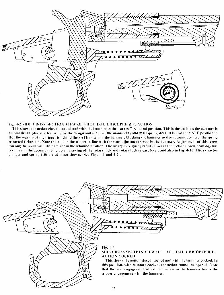
t i g . - t - 2 s l l ) [ . ( l t o s s S l ' . ( ' l l O \ \ l l ' . \ \ O ] " 1 ' H l . t . l ) . H . C H I C O P [ . ] ' . R . I . A ( . ' | ' I O \' l ' h i s
s h r l u s l h c a c l i o n c l o s c d . k l c k e d a n d l r i l h t h e h a r n n r e r i n l h e " a l r c s l " r e b o u n d p o s i t i o n . T h i s i s l h e p o s i l i o n l h e h a r n n t c r i sa u l o n r a t i c a l l r p l a c e d a l l c r I ' i r i n g b r t h c d e s i g n a n d s h a p e o f l h e m a i n s p r i n g a n d m a i n s p r i n g s l r u l . l l i s a l s o l h c S A I ' I ' . p o s i l i o n i nl h a l l h c s e a r l i p < l f l h e l r i g g c r i s h c h i n d t h e S A t l . - n o l c h o n l h c h a m r n c r , b l o c k i n g t h e h a l n m c r s o l h a l i l c a n n o t c o n t a c l l h c s p r i n gr c l r a c l c d f i r i n g p i n . \ o l c l h e h o l c i n t h c l r i g g c r i n l i n c r v i t h l h e r e a r a d j u s l r n c n t s c r e * i n l h c h a m n r e r . A d i u s l n t e n l < l f t h i s s c r e nc a n o n l l b c r n a d c n i l h l h c h a r n n r c r i n t h c r e b o u n d p o s i l i o n . T h e r o t a r l l o c k s p r i n g i s n o l s h o w n i n l h c s e c l i o n a l r i e l v d r a l r i n g s b u li s s h c n n i n l h c a c c o n l p r n l i n g d e l a i l d r a n i n g o f l h e r o t a r l l o c k a n d r o t a r l l o c k r e l e a s e l c r c r , a n d a l s o i n t i g . , l - 1 6 . T h c c r l r a c l r l rp l u n g c r a n d s p r i n g ( 1 0 ) a r c a l s o n o l s l t o l r n . ( S c c t i g s . 4 - l a n d 4 - 7 ) .
I"ig. ;t-3sil)[ . c]Ross s[.( t ' to\ \ I [ . \ \ ot IA( TtO\ ( (X Kl . . l )
' l ' h i s s h o n s l h c a c l i o n c l o s c d . l o c k c d a n d n i l h l h e h a n r n r c r c o c k e d . I n
l l r i s p o s i t i o n , u i t h h a r n n r c r c o c k c d , l h c a c l i < l n c a n n o l b c o p c n e d . N o l clha l thc scar cngagc lncn l ad . ius l rncn l sc rc$ in thc hamnrer l in r i t s thet r iggcr cngagerncn l $ i lh lhc l ranr rncr .
CHI( 'Ol ' [_ ]

B ORECENTERLINE
I ie. , l-4su)t. ( Ross sr..( l'toN \ ll..\\ ol'T I I l . t , ' . 1 ) . H . C ] H r C O P l . . r . - R . t . A C . l ' r 0 N O P F - N
' l 'h is d ra lv ing shous lhc ro la r l l< lck ro ta ted lo lhc un lockcd
pos i l ion and lhc ro ta r l lock re lcasc lc rc r cngaged l r i th thcro la r l k rck to ho ld i l in tha l pos i t ion lo be rc leased aga inau lurna l i ca l l r l r hen lhc ac l ion is c loscd .
' l ' he d rawing a lso
s h o w s ( l r e e \ l r a c l o r e r l c n d c d r c a r n a r d .
2"-a
tA---+
E"
t ' ie . 4-5 Rl-C[ . lV! .R PAR' ISI 'h is drawing shows a rear end v iew of the receiver r ing before i t was machined octagon in shape but grooved for the receiver
s ides, machined f la t at the bot lom and wi th one receiver s ide in p lace as i f s i lver brazed there. Also shown is a s ide v iew of thereceiver r ing and the barre l shank which had been f i t ted to i t wi th both par ts machined for the extractor , and one of the two l , /E"th ick receiver s ides dr i l led, as indicated b1 dot tcd l ines, to accept shor t p ieces of s i lver so lder wire pr ior to the s i lver braz ingopcrat ion. See text for deta i ls .
5tl
t lu
t lt-l |-|
I
2"1
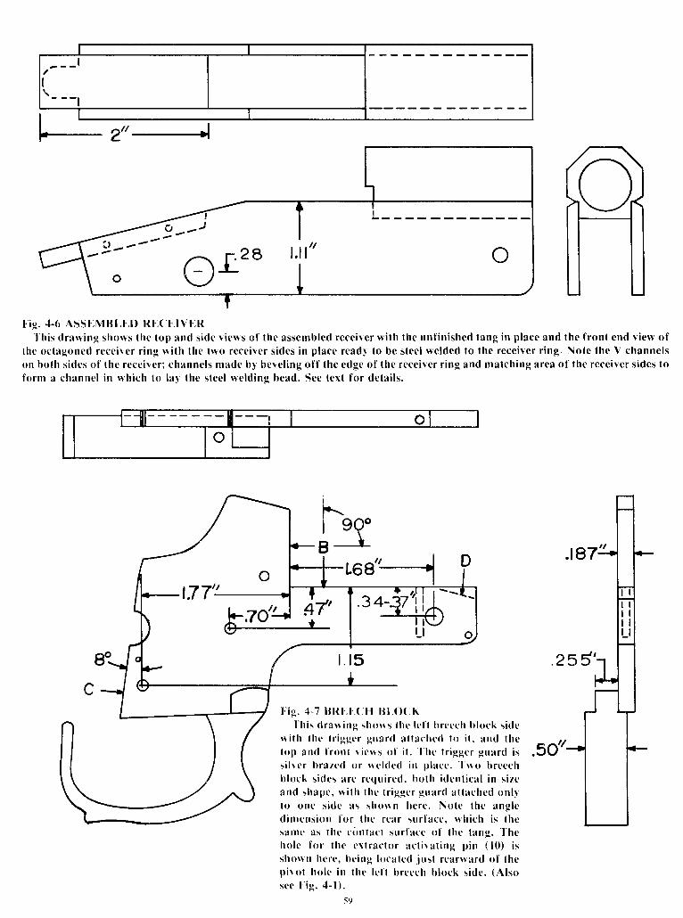
t ig . 4-6 ASSI-MBLt D R[ ,Cl , lV[ -RThis draning shows lhe top and s ide v iews of the assembled receiver wi th the unf in ished tang in p lace and thc f ront end v iew of
lhe octagoncd recei l 'er r ing wi th the two receiver s ides in p lace readl to be steel welded to the receiver r ing. Note the V channelson both s ides of the receivcr ; channels made b l bevel ing of f the edge of the receiver r ing and matching area of the receiver s ides toform a channel in which to la l the s leel weld ing bead. See text for deta i ls .
t ig . 4"7 l tRl ' .F.CH t lL(X'K' I 'h is
dranins shor ls lhc lc f | brccch bkrck s idcn i t h l hc l r i gge r gua rd a l l ac l red l< l i t , and thc _ ^ ,rop and f ron t r i o r s o f i l . Thc t r i gge r gua rd i r " 5O 's i l r c r b razed o r ne ldcd i n p lacc . Two b reechhlock s ides are requi red, bolh idenl ica l in s izeand shape, rv i th thc t r iggcr guard at (ached onl ll o onc s idc as sh< ln n hc re . No le t he ang l cd in t cns ion fo r t hc r ca r su r facc . r h i ch i s t hesanle as lhe c i rn lac l sur l 'acc of lhe lang.
' l 'he
ho le f u r t hc c r l r ac lo r ac l i \ a t i ng p in ( 10 ) i sshurrn hcrc, bc ing localed jus l rcar lvard of thcp i ro t ho le i n l he l e f l b r cech b lock s i de . (A l soscc l ' ig. zl- I ) .
59
h--I eQ"B}
1Y--i- j " -A . r , 28r.{ - ) r
o \-/
ot':ul]6
Lt o

o
- - - - \
hr,;,;'
rl- llt/\
lrl
t ' i s . 4 - t t t l l t l \ ( ; P l \ B I .OCK ASSI .M l ]1 . \Thc f i r i ng p in asse rnh l ) , shon ing f ron t and s ide v iens o f t he f i r i ng p in
bklck, t ' ronl and s ide r icws of lhc breech b lock faceplate and s ide r ier+ of lhcf i r ing p in and rc l rac lor spr ing. 1 'he grot l red top of the f i r ing p in b lock serrcsas lhc loading p la l fornr . A \ \ 'carer scopc mount screw is uscd t t l j t l in thc par ts
logcl l t r r i ls : l tor r n in l ' igs. { -2. { -3 und 4-{ '
l ' i s . , 1 -10 HAMMI ' -RThc han rn re r o f l hc
ac l i on . Fu r the r dc ta i l ss l ruc t i ons . (A l so scc;t-3 ).
.33"
( I t I ( OPl . . l ._ I t .F.a rc g i r cn i n t hc i n -l ' ' ics . : l -1 . - l -2 and
l ' i g . . l -12 F .XTRA( I 'ORS i d e a n d e n d r i c n s
po l l c r b lock . (A lso scc, l -3).
trT.25
P0\\ [-R BI,OC Kruf the cx l ract0r
l ' ics. -1-1. . l -2 and
f-e?4 gt25"
l ' i g . '1 -9 l ' .X ' l 'RAC' tO l tl i c a r , s i d e a n d t o p r i e n s o f l h c c r l r a c l t l r . ' l ' h c e x l r a c t o r f i t s b e t n e e n
l h c b o l l < l r n o f l h c r c c c i r e r r i n g a n d l h c l o p o f t h c b r c c c h b l r l c k e x ( e n -
s i o n s . ' f h c t o p r i c n s h o n s l h e n o ( c h p r t l r i d e d f o r t h c p l u n g e r n h i c h
a c l i r a l c s l h c e r t r a c l o r r c a r n a r d u p t l n < l p e n i n g ( h e a c ( i r l n . ( A l s o s c c
t ' i g s . , l - 1 , . 1 - 2 a n d ' 1 - ; l ) .
nIII ' :ELEH
f-.zo"l*- t.85"---l l*-.a24I i g . ; t - l l M A I N S P R I N ( ;
S idc and cnd r i ews o f t he ma insp r i ng s t ru t and s l ru l s l ee rc . (A l s t l
see I iss. 1-1, 1-2 and , l -3) .
t l
l i o
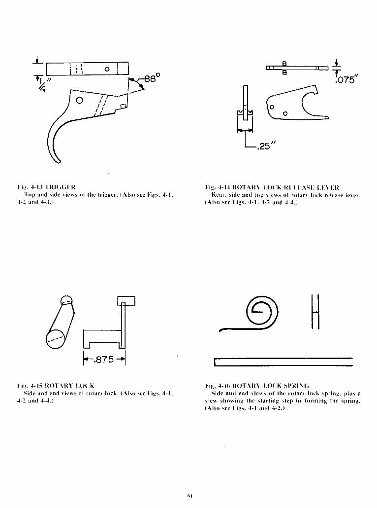
l ' ic. {- I 3 l 'R | (; (; l ' . l t' I ' o1 l
and s i c l c r i o r s o l l hc l r i ggc r . (A l so see I i gs . , l - 1 ,. l -2 and { -3. )
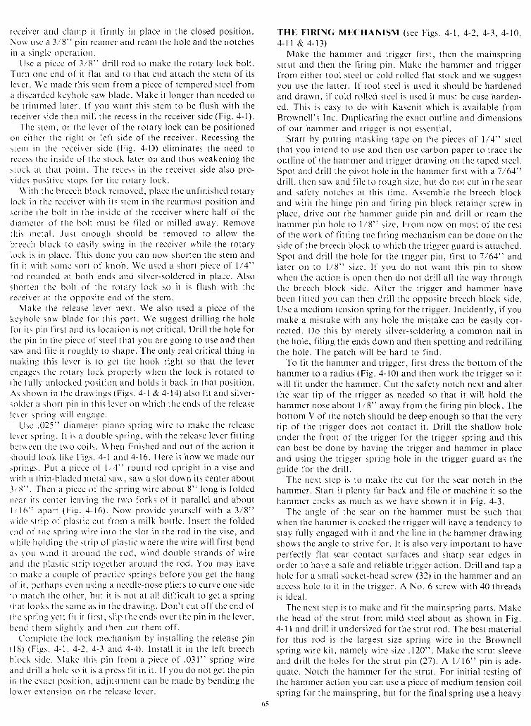
t ' ig . J-15 l tOl Al t \ l . (X KS ic l c an t l cnd r i cns o l r o l i r r \ l ock . (A l so
- l -2 and . l -1 . )scc I igs. , l - l ,
l-
\zd'
fi,FFie. 4- l , t ROTARI l .O( K Rl . l . I . .ASl . . t .1 . . \ [ . l t
Rca r . s i de and l op r i cus o l r o l a r r l uck r c l easc l c re r .( A l s o s c e l ' i e s . , l - 1 , 4 - 2 a n d 4 - 4 . )
9|]t ' ie . . t -16 RO-IAR\ l . (X K SPRI\G
S ide and cnd r i ens o f l hc ro la r l l ock sp r i ng , p lus ar i cn shon ing thc s ta r t i ng s t cp i n f o rn t i ng t he sp r i ng .(Also see Fics. , l - l and ; l -2 . )
I
2

/ /
t - . z /
t i e . 4 - 1 7 S T O C KThis is a r r r id-scc l ion dra l l ing of lhc stock used on our c lHtcol 'L , [ - R. t ' . r i f le . Thc
dot tcd l ines sht tw lhe areas to be roulcd or sa lved oul nhen making laminated stocksas exp la ined i n l hc t cx l .
02

Ins t ruct ions and Sequence of Operat ions for Making the F.D.H. CHICOPEE R.F. Act ion
As yorr rnay a l ready ha 'u 'e not iccd i f you have exarnined thecl ra* ings, ue h: rvc not prov idcd you u ' i th cvery speci f icat ionor a l l d i rnensions on r lc ts t of the par ts . \Ve have done th isp t t r posc l v . I l , t o r e ra rnp le , i n F ig . z1 -10 u ,e had supp l i ed a l l o fthc d i r r rensions needed to ntake the harnnier drarv ing a t ruernechanical dra* ' ing, i t lvould have col ,ered an ent i re page andonc look at i t ancl 1 'ou sure ly vr ,ould havc throrvn up youfhands and g i r ,en up o l t the ent i re pro ject . Making such acl ra* ing u,ould have bet . r r r cr l ' d i t t icu l r , but far lcss d i f f icu l tt l ran i t *oulc l bc I 'or you to ntake the hantrner according tothosc d in rens ions . I ns t cac l , u , [ r a t u , c have done i s t o g i ve on l ythc nrost cr i t ica l d i r t rensions and the eract s ized drarv ing oft he pa r t s so t ha t vou ca l t shape each pa r t i o you r own l i k i ng .l r r t hc cu t t i n_s o l , l t and n rak ing o f n tany o f t he pa r t s , such asthe harr i rDer, \ \ 'c suggest ! ,ou put ntasking tape on t l re p iece ofsteel l rorn u 'h ich the hantrncr is to be rnade, and using carbonpaper t racc the or . r t l inc of t l tc hantnrer on i t , spot the hammerp in ho l c and d r i l l i t and then rough saw, f i l e o r mach ine theharnnier 1o shal rc . Leave a l i t t lc er t ra ntcta l on i t for the f ina lf i t t i r r g . l 1 ' you do no t l i k c t he shapc o f t he spu r on ou r ha r r -nrcr , then go ahead and shape i t to your own fancy. Makingthe harnrner and other par ts in th is way is far easier than mak-i ng i t acco rd ing to a sc t o f ' f i gu res . And , i f i n t he mak ing o fthe par t , you l ' ind that you have removed a b i t more metalthan our drarv ing or d intensions show, or you have a holedr i l led a t 'e ' , r ' thousi rndths of f , i t probably won' r mat ter as youcan compensate fc l r i t in thc rnaking and f i t t ing of anotherpa r t t o i t . Fo r cxa rnp le , t he hamnre r and t r i gge r , once )ouunderstand thc re lat ionship of ' the sear and safety reboundncl tches, thel ,do r . rot ha 'u,e to be made exact ly as shown in thedra*, ings, as long as the sear notches and p ivot holes areplaced in the corrcct posi t ions. The ent i re design of theCHICOPEE act ion is such that rhere are few v i ta l speci f ica-t i ons t o f o l l ou ' .
R l -C t - t \ l .R R ING (see F igs . 4 -1 ,1 -5 & 4 -6 )Make th is par t f ronr a p iece ot '1" d iarncter sof t s teel round
stock. Tr i rn to lcr rgth and then dr i l l or bore the barre l shankho le . A t ap can be used to t h read th i s pa r t and 5 /8 x 18 th readis ideal . The barrc l should be threaded in a la the setup. I f ther i f ' le is being rnade for the.22 Long Ri f le car t r idge, i t is per-missable to omit the threads and have the barre l a snug s l ip f i tin to the receiver r ing and held in p lace by a couple of crosspins or socket-hcad set screws. A d iameter c f l /2 or 5,28" isadequatc for a s l ip in f i t r ing. F i t the barre l and turn thebreech end f lush rv i th the receiver r ing. Wi th the barre l inp lace in the receiver r ing make the cut (A) for the extractor .Thc barre l can now be removed. Then mi l l in the grooves andthe f la t on the receiver r ing as shown. I f you want the receiverr ing octagonal in shape on top then th is can be done next or i tcan be done af ter the recei ler s ides have been at tached.
R[-CF-MR SIDF]S (see Figs. 4-1, 4-5 &.4-6)Use 1/8" rh ick cold-ro l led f la t srock, two ident ica l p ieces
are requi red. Do not dr i l l an"v holes in these par ts at rh is t ime.
BRI- ICH BLOCK SIDES (see Figs. 4- l & 4- t )Use 3/16" or equivalent th ickness cold-ro l led f la t s tock
and t rvo ident ica l p ieces are requi red. Remove the scale sur-face f rom these par ts as wel l as f rorn the receiver s ides. Most
d imensions are not cr i t ica l excepr that the sur faces (B) thatform the top of the breech b lock extension and the face of thestanding breech must be level and square to each other , andthe rear sur face (C) at not less of an angle than shown. Pro-ceed as fo l lows to make rhese par ts . On a p iece of th in card-board make a carbon t rac ing of the breech b lock s ide f romour drawing. Cut out your carbon t rac ing for a pat tern to useto saw out two rough breech b lock s ides f rom the steel s tock.Using the pat tern a lso spot and center-punch the hammer andhinge p in holes on one of the sawed out s ides. Now c lampboth s ides together and dr i l l an 11/64" hole through boths ides at t l re h inge p in locat ion and a l /64" hole at the ham-mer p in locat ion. These holes f i t ted wi th snug f i t t ing p ins wi l lthen be your guide holes for a l l the remain ing operar ions onthe breech b lock s ides so that both wi l l be ident ica l . Markeach s ide in some manner to indicate r ight and lef t s ide andreta in th is posi t ion. Your next s tep is to machine or f i le thetop of the extension and standing breech face level andsquare.
ASSEMBLING THE RIICEMR (see Figs. 4-5,4-6)Before at taching the receiver s ides to the receiver r ing i t is
recommended that you spot and dr i l l the h inge p in hole in oneof the s ides. Do th is by c lamping one s ide and the receiverr ing together on a board or metal p late wi th the f ront of thereceiver r ing f lush wi th the f ront of the receiver s ide. In thesect ional v iew drawing (F ig. 4-2) you wi l l note that the stemof the extractor and the breech b lock face p late (7) f i t betweenthe breech b lock and the receiver r ing. Therefore, to spot anddr i l l the h inge p in hole accurate ly posi t ion p ieces of meral ofthe th ickness of these two par ts , or bet ter yet , the p ieces ofineta l that you wi l l use for these par ts ( l /8" for the face p lateand 1/64" lor the extractor s tem) in p lace, c lamp the breechblock s ide in p lace and dr i l l the h inge p in hole us ing the holeal ready in the breech b lock s ide as the guide. Now you areready to assernble the receiver s ides to the receiver r ing. Werecomnrend s i lver braz ing us ing the s i lver-solder wire. Youwi l l havc to f igurc out a way o i hold ing the three par tstogether and a l igned so that the brazing is made sure andeasy. \d 'c do i t by us ing three C-c lamps and two spacers. Thespacers must be the same ' ,v idth as the d is tance between thegrooves in the receivcr r ing for the receiver s ides, or.630 - .635 " . Makc the rn t ' r on r a p iece o l l / 1 " o r 3 /8 " s tec lp ipc . I f ' you ha r ,e a l ready rnade thc t ang (33 ) t hen i t can beused as a spacer. Placc onc spacer at the lower edge of thcreceiver belorv the receiver r ing rv i th a c lamp to hold thcrecciver s ides in propcr p lace on the receiver r ing. Use anotherc lamp l ' r o rn t he top o l ' t he r ccc i ve r r i ng t o t he bo t tom o f t herecei 'n ,er to hold the three par ts together in that d i rect ion.Place the second spacer at thc rear of the receiver and c lamp i tin p lacc. Vise-gr ip weld ing c lamps can be used instead of theC-c lamps. \ I 'hen you are assured that lvhatever c lamping ar-rangement you want to usc wi l l work, d isassemble the par ts ,c lean the arcas r .vhere the s i lver-solder must go, spread on ath in even layer of f lux, inser t the p ieces of s i lver so lder wireinto the holes in the receiver s ide as shown in F ig. 4-5,reassemble and then apply hcat f rom an oxy-acety lene torchunt i l the s i lver so lder has f lowed ent i re ly throughout bothjo ints . Be sure that the extractor cut in the receiver r ing is tothe rear . The tang must not be brazed in unt i l the breech

block has bcen assembled and f i t ted. Instead of s i lver braz ing
)ou can a lso usc e lect r ic-arc u,e ld ing, preferably the M. l .G.* i r e u ' e l d i ng . I n F ig .4 -6 , sho rv ing the f ron t v i ew o f t herccei" 'er , both s ides of thc receiver r ing where i t jo ins thereceivcr s ide has to be bevelcd of f as wel l as the receiver s ideto prov ide a channel in rvh ich to lay a bead of weld.
' IHF. I ' .XTRACTOR (see Figs. 4-1, 4-2, 1-3, 4-1 & 4-9)
Use tuo p icces c l l mi ld s teel s i lver brazed together . Makethe stenr or base f rom a p iece of 7/64" th ick steel 5/8" wideanC about 2% " long to bc t r imnred shor ter la tcr on. Make thec\ t ractor l ip or l iook t l 'om l /8" th ick stock. Star t wi th a p iecel" long and l /2" r ,v ide and s i lver braze i t squarely on the endol ' thc base. Then i t is f i t ted b-v f i l ing or machin ing to f i t c lose-l r ' . This f i t t ing can bc donc rv i th the barre l in p lace or wi thouti t in p lace. ln e i ther casc, af tcr i t is l i t ted so i t s l ides back andfor th * ' i thout b inding, thc l ip or l iook must be f i led orr r rachined f lush l l ' i th thc breech end of thc receiver r ing andb a r re l .
I f -vou iv is l i you can norv chamber the barre l . F i rs t carefu l lyl ' i le a shal low U-notch in the top of the er t ractor hook leveln i th the borc or just cnough to a l lc l rv the entry of thechanrber ing reamer p i lo t in to thc bore wi th the extrac lor inp lace. Thcn, us ing cut t ing o i l on thc f in ish chamber ingrcamer, and turn i r rg i t rv i th a tap wrench, rearn the chamber.Thc correc l depth of the chamber is reached when you canchamber a car t r idge in the chamber so that i ts head is f lush,o r .001 " be lou ' t he b rcech cnd . La te r on a f t e r you have f i t t edthe f i r ing p in 1 ' 'ou must f i le a narrow groove dorvn the centerof the er t ractor facc to pfevent the f i r ing p in f rom catchingshou ld i t no t r c t rac t .
ASSI,MBI, ING AND } ' IT ' I ING THE BREI]CH BLOCKBef 'ore the breech b lock halves can be assembled and f i t ted
two i tems u ' i l l have to bc rnade. l -hey are the f i r ing p in re-ta ine r b lock asscn ' rb l y ( see F igs . 4 -1 ,4 -2 ,4 -3 ,1 -4 & 4 -8 ) , andthe t r i gge r gua rd ( scc F igs . , 1 -1 ,4 -2 & 4 -7 ) . Use 1 , / 4 " t h i ckmi ld s teel for the f i r ing p in reta iner b lock and make i t asshorvn but leavc i ts upper end ungrooved, and do not dr i l l thef i r ing p in hole; both of these jobs arc best done later on. Usel /8" tool s teel for the brecch b lock face and leave i ts top sur-face unf in ished. F i t the t \ \o par ts together wi th a 6x48 scopemount ing screw. Nlake the t r igger guard by sawing i t f rom a3/8" or l , /2" th ick p iece of rn i ld s teel s tock, sawing and f i l ingi t to shape as shou'n, or make i t f ronr a p iece of 3/8" or l /2"square rod and bending and l i l ing i t to shape. When you havei t shapcd to your sat is fact ion and have a 1/4" th ick basemachined on i t dr i l l and tap the hole for the t r igger spr ing.rapping t t re lower end about hal f way for a 6x40 socket-headscrew. The t r igger guard is norv ready to be at tached to the in-s ide of one of the s ides. For the s i lver-solder ing dr i l l threesmal l holes in to one s ide o l the base a lmost a l l the waythrough into which you inser t p ieces of rv i re s i lver-solder . Ap-ply f lux and c lamp the t r igger guard in p lace to the ins ide ofthe le f t breech b lock s ide and then heat unt i l the s i lver hasf lowed throughout the jo int . Or, the t r igger guard can be at -tached wi th arc-weld ing or rv i t l i a screw.
With the two breech b lock guide p ins in p lace c lamp the f i r -ing p in b lock assembly between the breech b lock s ides anddr i l l and tap the hole for the reta iner screw. This can be 6x32,6x40 or 6x48 screw.
At th is point make whatever minor adjustments are needed
to s l ip thc assernblcd breech b lock in the receiver . The breechblock face must be a c lose f i t against the breech b lock on boths ides. Now, wi th the extractor in p lacc and rv i th only thehinge p in guide p in removed, c larnp the breech b lock in t t rereceiver wi th i t forced as t ight ly up and forrvard as i t wi l l go.Use a No . l 5 d r i l l and r v i t h i t d r i l l t h rough the h inge p in ho leal ready in one receiver s ide and through both breech b locksides and on through the opposi te recc iver s ide. F in ish thehole wi th a3/ 16" p in reamer. The hole is nor .v ready to accepta h inge p in made o f d r i l l r od .
At th is point you are ready to rcmove some metal f rom thetop f ront corners of the breech b lock er tensions as indicatedby the dot ted l ine (D) in F ig. 4-7. Be carefu l here as i t is easyto remove too much mcta l - for now remove just enough toal lorv the breech b lock to sr ,v ing about two th i rds open.
f ITT ING AND INSTAt .L ING TH l . TANG (see F igs . , 1 -1 ,
4-2, 4-3, 4-1 & 4-6)Use a p iece of 1/4" th ick rn i ld s teel about 2" long and
.630-.635" r . r ' idc. Machine or f i le one end of i t to an angle toI i t per fect ly agains l the rear of the brcech b lock. Use coldblue as a spot t ing agent to achicve a c lose f i t against bothbreech b lock s ides. Clarnp the tang i r . r p lacc and t ry openingand c los ing the brecch b lock. l f there is any b inding i t may beduc to the top rear corners of the brecch b lock s ides not beingrounded of f enough or that they pro ject too far above thetang. When you havc obta ined a proper f i t c lantp the tang inplace and dr i l l two 5/64" holes about 5/8" apar t through onereceivcr wal l and 3/16" or so in to the s idc of the tang and in-ser t guide p ins in to them. Nolv rernove evcryth ing f rorn thereceiver , f i le c lean the contact ing sur faccs betrveen thereceiver s ides and tang, spread a th in layer of paste s i lver-solder on the contact ing areas of thc tang, put the tang andguide p ins in to p lace, c lamp and heat unt i l the s i lver-solderhas mel tcd. Instead of s i lver-solder ing th is par t can a lso bearc-weldcd in p lace. F i le of f the pro ject i r . rg er . rds of thc guidepins and any metal that pro jects above the tang. The tang canbc f i led rounded on top. At th is point you can a lso ntachineor f i le the rear end of the tang narrower and round i ts end(Fie. a-6) , as rvel l as dr i l l and tap the hole for the tang screw.
- t H l l R O T A R I L O C K ( s e e F i g s . 4 - 1 , 4 - 2 , 4 - 3 , 1 - 4 & 4 - 1 5 )
This mechanisrn locks the brccch b lock c losed and i t con-s i s t s o f t h ree ma in pa r t s p lus p ins . Thcse pa r t s (F ig .4 - l ) a rethc rotary lock (14) , rotary lock re lease Iever (16) , rotary Iocksp r i ng (15 ) and two p ins . The func t i on o f t he re lease l eve r i sto hold the rotar .v lock in thc unlocked posi t ion u 'h i le the ac-t ion is open and to re lease i t again af ter the act ion is c losed.To make these par ts and f i t them, proceed as fo l lorvs. F i rs tspot the locat ion for the rotary lock hole through the receiver .This hole must be on the juncture l ine rv i th the rear of thebreech b lock so that hal f thc d iameter of the rotary lock wi l lcngage wi th the breech b lock. Spot the correct center b1 'p lac-ing the breech b lock c ln the outs ide of thc receiver iv i th thehinge p in in p lace and scr ibe a l ine against the rear of thebreech b lock on the receiver s ide. Dr i l l a23/64" hole at th islocat ion through both receiver s ides. Inser t the assembledbreech b lock in the receiver and rvhi le i t is in the fu l ly c losedposi t ion scr ibe hal f -moon l ines on the rear of the breech b locksides through the hole just dr i l led. Remove the breech b lockand f i le the hal f - rnoon notches in the breech b lock s ides ac-cord ing to the scr ibe marks. Reinser t t l ie breech b lock in to the
rcceivcr and c la lnp i t f i rmly in p lace in the c losed posi t ion.Now use a 3/8" p in reanrer and ream the hole and the notchesin a s inglc t . lpcrat ion.
Use a p iece o f 3 /8 " d r i l l r od t o rnakc the ro ta ry l ock bo l t .Turn one end o l ' i t f la t and to that end at tach the stem of i tsl lcr . \ \ 'e nrade th is s tcm f rom a p iece of tempered steel f roma discardcd kei 'ho lc sau b lade. Make i t longer than needed tobe t r i n rn red l a te r . l f ' you wan t t h i s s t cm to bc f l ush w i th t herece i ve r s i de the r r r n i l l t he recess i n t he r cce i ve r s i de (F ig .4 -1 ) .
Thc stcnr , c l r thc lc . "cr of thc rotary lock can be posi t ionedon c i thcr thc r ight or le l t s ide of the recei r , 'er . Recessing thes tem in t he r ccc i vc r s i c l c (F ig . . 1 -D ) c l i r n i na tes t he need torccess the i ns ide o f t he s tock l a te r on and thus weaken ing thestock at that point . Thc recess in the receiver s ide a lso pro-r i c l es pos i t i r . e s tops fo r t hc ro ta ry l ock .
\ \ ' i t h t he b reech b lock ren ro led , p lace the un f i n i shed ro ta rylock i n t hc r ccc i i c r * ' i t h i t s s t cn r i u t he rea rmos l pos i t i on andsc r i be t he bo l t i n t he i ns i c l c o l ' t he r ccc i ve r r vhc re ha l f o f t hcdianrctcr o1- thc bol t r lust be I ' i led or mi l led arvay. Removeth is rncta l . . lust cnough should be rernoved to a l lorv theb reec l i b l ock t o cas i l y , su ing i n t hc recc i vc r wh i l e t he ro ta rylock is in p lacc. - [h is
donc yo] . I can now shorten the stem andl- i t i t u i th sorne sor t ot 'knob. \ \ 'e used a shor t p iece of 1/4"rod rounclcc l at both ends and s i lver-soldered in p lace. Alsoshorten thc bol t o f thc rotary lock so i t is f lush iv i th therece i r . e r a t t he oppos i t e end o f t he s tem.
Nlake the re lease lever next . We also used a p iece of thekcy 'holc sau,b lade f 'or th is par t . \ \ 'e suggest dr i l l ing the holetor i ts p in f i rs t and i ts locat ion is not cr i t ica l . Dr i l l the hole fort he p in i n t he p iecc o f ' s tee l t ha t you a re go ing to use and thensa* and l ' i lc i t roughly to shape. The only real cr i t ica l th ing inrr rak ing th is lcvcr is tc l gct thc hook r ight so that the levercngagcs thc rotar) , lock propcr ly \ r 'hen the lock is rotated tothe fu l l y ' un lockcd pos i t i on and ho lds i t back i n t ha t pos i t i o r r .As sho*n in t l ie dra* ' ings (F igs. 4- l & 4-1.1) a lso f i t and s i lver-so l c l c r a sho r t l r i n i n t h i s l oc r on r vh i ch t he cnds o f t he re leaselnc r sp r i ng * ' i l l engage .
Usc .025 " d ia rne te r p i eno sp r i ng \ \ i r e t o n iake the re leaseloer spr in-u. l t is ar doublc spr ing, r ' r , ' i th thc re lease lever f i t t ingbctr rccn thc t r i 'o co i ls . \ \ ' l ien f in ishcd and out of thc act ion i tshou l c l l ook l i ke F igs . z1 - l and 4 -16 . He re i s how u 'e madc ou rsp r i ngs . Pu t a p i ccc o1 '1 , / 4 " round rod up r i gh t i n a v i se andui th a th in-b laded nreta l sa\ \ ' . sa\ \ 'a s lot dol l 'n i ts cen. ter aboutJ , ' 8 " . Thcn a p i cce o t ' t hc sp r i ng u i r c abou t 8 " l ong i s f o l dedncar i ts center lcav ing thc t \ \ 'o forks of i t para l le l and aboull . 16 " apa r t (F ig . ' 1 -16 ) . No rv p rov ide - vo r r r se l f w i t h a 3 , / 8 "r i i dc s t r i p o l ' p l as t i c cu t l ' r on r a n r i l k bo t t l e . I nse r t t he f o l dedcnd o t ' t hc sp r i ng * ' i r e i n to t hc s l o t i n t he rod i n t he v i se , and*h i l c ho ld ing the \ t f i p o f p l as t i c uhe re t he r v i r e w i l l f i r s t bcndas )ou u ind i t a round thc rod , u ind doub le s t rands o f i v i r eand rhc p las t i c s t r i p t oge thc r a round the rod . You may haveto make a coL rp l c o l ' p rac t i cc sp r i ngs be fo re you ge t t he hangof i t , pcrhaps er ,cn us ing a r recdlc-nose p l iers to curve one s ideto n ra t ch t hc o thc r , bu t i t i s no t a t a l l d i f f i cu l t t o ge t a sp r i ngt i rat looks the sanre as in thc c l rau ' ing. Dcln ' t cut of f the end oft hc sp r i ng ! ' c t ; f i t i t l ' i r s t , s l i p t he ends ove r t he p in i n t he l eve r ,bcnd theni s l i -uht l1- ancl the t i cut t l rent of f .
Cornplcte thc lock rnecl ianisrn by insta l l ing the re leasc p in(18 ) (F ies . ' 1 -1 , 1 -2 , , 1 -3 and .1 -4 ) . I ns ta l l i t i n t he l e l t b reechb lock s i dc . N lake th i s p in f r on r a p iece o f . 03 l " sp r i ng w i reancl dr i l l a hc l le so i t is a prcss f i t in i t . I f 1"ou do not gct the p inin t he c rac t pos i t i on , ad jus tn ren t can be rnade by bcnd ing thelouc r e r t cns io r r on t he re l case l eve r .
T H F I I I R I N G M F . C I H A N I S M ( s e e F i g s . 4 - 1 , 4 - 2 , 4 - 3 , 4 - 1 0 ,4- l r & 4 - r3 )
Make the hammer and t r i gge r l i r s t , t hcn the rna insp r i ngstrut and then the f i r ing p in. Make the hamrner and t r iggerf ronr e i ther tool s tcc l or co ld ro l led f la t s tock and we suggest-vor . l use the la t ter . l f too l s tce l is used i t should be hardenedand drau,n, i f co ld ro l led steel is used i t must be case harden-ed. This is eas-v to do rv i lh Kascni t rvh ich is avai lable f romBro* 'nel l 's Inc. Dupl icat ing the exact oLl t l ine and d imensionsof our harnmer and t r igger is not esscnt ia l .
S ta r t by pu t t i ng u rask ing tape on the p ieces o l ' l / 4 " s tee lthat you intcnd to use and then use carbon paper to t race iheout l ine of the hanrnrer and t r iggcr drarv ing on the taped stec l .Spot and dr i l l the p ivot holc in thc hammer f i rs t rv i th a 7, /64"dr i l l . then sarv and I ' i le to rough s ize, but do not cut in the searand saf 'e ty nolches at th is t inrc. Asscrnble the breech b lockand u ' i t h t he l i i nge p in and f i r i ng p in b lock re ta inc r sc reu i nplacc, dr ive out ihe harr inrer guide p in and dr i l l or rcanr theha rn rne r p in ho l c t o l / 8 " s i zc . F ron r now on n ros t o f t hc r cs tof ' the rvork of l ' i t t ing the f i r ing rnechanism can be done on thesidc of the brcech b lock to u. 'h ich the t r i -eger guard is at tached.Spo t a r rd d r i l l t he ho le I o r t he t r i ggc r p in , f i r s t t o l / 61 " andla te r on to l , / 8 " s i ze . l t ' you do no t \ r "an t t h i s p in t o sho rvu 'hcn the ac t i on i s open thcn do no t d r i l l a l l t hc way th roughthe breech b lock s ide. Al ' ter thc t r iggcr and hammer havebeen l i t ted ) 'ou can thcn dr i l l thc opposi tc breech b lock s ide.Use a r reCium tcnsic ln spr ing for the t r iggc ' r . Inc ident ly , i f younrake a mistake wi th an.v hole thc mistake can be easi ly cor-rected. Do th is b1 ' merely s i lver-sc lder ing a common nai l inthe hole, f i l i r rg the ends do."vn and then spot t ing and redr i l l ingthe hole. The patch rv i l l be hard to f ind.
To f i t the hammer and t r igger , f i rs t drcss the bot tom of thehammer to a radius (F ig. 4-10) and then work the t r igger so i tlv i l l f i t undcr the hammer. Cut the safety notch next and a l terthe sear t ip of the t r igger as needed so that i t wi l l ho ld thehammer nose about l /8" arvay f rorn the f i r ing p in b lock. Thebot tom V of thc notch should be deep enough so that the veryt ip of the t r igger does not contact i t . Dr i l l the shal low holeunder thc f ront of the t r igger lor the t r igger spr ing and th iscan best bc done by having the t r igger and hammer in p laceand using the t r igger spr ing holc in thc t r igger guard as theguide f 'or the dr i l l .
The next s tep is to nrake the cut for the sear notch in thehammer. Star t i t p lenty far back and f i lc or machine i t so thehammcr cocks as much as we have shown i t i n F ig .4 -3 .
The angle of the sear on the hammer must be such thatu 'hen the hanrnrer is cocked the t r igger wi l l havc a tendency tostay fu l ly engaged wi th i t and the l ine in the hammer drawingshorvs thc angle to s t r i r "c for . l t is a lso ver f important to havepert 'ect11, f la t scar contact sur faces and sharp sear edges inordcr to ha" 'e a safe and re l iab le t r igger act ion. Dr i l l and tap ahole f 'or a srnal i socket-hcad screw (32) in the hamn'rer and anaccess hole to i t in the t r igger . A No. 6 screw wi th 40 threadsi s i dea l .
The r rcr t s tep is to inakc and f i t the mainspr ing par ts . Makethe head of the st rut f rom mi ld s teel about as shown in F ig.4- l I and dr i l l i t unders ized for the st rut rod. The best mater ia lfor th is rod is the largest s ize spr ing w' i re in the Brownel lspr ing rv i re k i t , narnely,wire s ize .120". Nlake the st rut s leeveand dr i l l the holcs for the st rut p in (27) . A l /16" p in is ade-quate. Notch the hammer for the st rut . For in i t ia l test ing ofthe hammer act ion you can use a p iece of medium tension coi lspr ing for the mainspr ing, but for the f ina l spr ing use a heavy
65
tcn\ io l l spr ing that rv i l l just s l ip over the st rut rod. Before anyrnore I i t t ing is dc lnc r -ou s l iou ld now make and insta l l the f i r -ing p in. Spot and c l r i l l a 5/64" hole through the breech b lockl 'ace so that a p in througl ' t i t centers in the bot tom of the car-t r i dge r i n r r eccss o f ' t he cha r l be r . A f t e r d r i l l i ng t h i s ho le andcl icck in-c that i t is correct l ) ' p laced, assemble the breech faceto the I ' i r ing p in b lock and n ' i th a dr i l l , spot a hole on thetront o l thc f i r ing p in b lock. Remove the breech face and dr i l l
a l l / 64 " ho le i n t hc l i r i ng p in b lock t o 1 /8 " o f go ing a l l t her i a l ' t h rough . Fo l l ou ' t h i s b5 'go ing a l l t he r vay t h rough w i th a
9/6,1" dr i l l . N ' lake thc i i r ing p in about as shor 'vn in F ig.4-8l ' rorn dr i l l rod. F in ished and in p lace wi th a ret ractor spr ing. i trnust pro ject .035" t ' rom thc rear lvh i le at the same t ime i ts t ipis l lush u ' i th the breech facc. Fr . r l ly depressed so i ts base ist ' lush u i th thc rear of thc b lock, i ts t ip should then protrude
.035" or a thc lusandths or so l r lore.Nou cornes t l ie f ina l l ' i t t ing. l t is important for the safe use
ol ' th is r i f le that the f i r ing ntechanism funct ions as we design-ed i t , and c lnc of the dcsign l 'eatures is the rebounding ham-rner . l t is the act iorr of thc mainspr ing and st rut against thehi i r lnrer that br ings abclu l the rebound automat ica l ly af tert ' i r i r rg and a l lorvs the t r igger to move behind the safety notchto prcver l t thc hammer f rom contact ing the f i r ing p in unlessthc t r iggcr is pul led. \ \ ' i th thc complete f i r ing mechanism inplacc on onc breech b lock s ide i t is easy to see the act ion ofrhe s l ru l against the hantnrcr . F i le or n lachine the st rut so thati t nornra l ly holds the hamntcr nose of f to about 5/64" f romtouchir . rg the ret racted f i r ing p in. The t r igger t ip , as wel l as thesatet-v nc l tch, ntus l be so madc that the t r igger t ip is f ree torno re beh ind the sa ie t y ' no t ch ye t c l ose enough to s top thehi inrnrcr and prc lent i t f rorr i contact ing the f i r ing p in i f theharnnre r is pushcd fonvard, or acc identa l ly knocked forward,or i f thc harnmer s l ips l ' rom undcr the thumb whi le cocking i t .You need only ' enough rebound to a l low the above to takeplacc, more rcbound than necessary reduces the force of thehamnrcr s t r ik ing the l i r ing p in. To increase rebound move-mcnt e i ther deepen the st rut t to tch in the hammer or shor tenthc round push ing end o f t he s t ru t , o r r emove some me ta lI ' rorn the uppcr l 'ace of the hantmer. To decrease reboundsho r ten the uppe r pa r t o f t he s t ru1 .
At about th is point y 'ou rv i l l d iscover that the tang inter feresr i i th cocking the hamnier and the opening of the act ionbccause the haninter spur contacts the tang. To remedy th is anotch has to be cut in the tang to a l low par t ia l passage of thehan rmer spu r (F ig .4 -3 ) . The no tch can be made u ' i t h a f i l e .You ma1 'a l so have to rnake the hammer spu r t h i nne r o rlundercut i t more so that i t does not contact the rotary lockrc lease le i , 'er . Anyrvay, what you want is to have the act ionopen sul ' f ic ient ly for adequate extractor movement. Evenbcl 'ore hal ' ing rcached th is point you rv i l l probably have to f i lea b i t morc of l 'o f the top t ' ro l t t o f the breech b lock extensions.Be 'u 'ery ' carefu l here as you want th is to be the stop for theclpening srv ing of the brcech b lock. Af ter you have taken careof the stop and the notch in the tang, i t is then t ime to f in ishof ' f the top of the breech b lock and groove i t to serve as theloading p lat forrn. You ntere ly f i le or rnachine the groove deepcnough so that a car t r ic lge p laced on i t can be pushed into thechamber and a car t r idge or empty case extracted f rom i t .
t I \ ISH IN( ; TH l . UXTRACTOR (see F igs . 1 - l , 4 -2 , 1 -3 , 4 -4& 4_9)
The er t ractor has tu 'o sources of power, and rvhi ie e i therone rn ight be sat is factory by i tse l f we suggest you employ
both. Thc spr ing backed p lunger (10) f i t ted in the f ront end of
one brcech b lock er tension and engaged in a notch in the ex-
t ractor base provides the in i t ia l power. Use a1/64" dr i i l rod
for th is p lunger. Thc second source to push the extractor a l lthe ' ,va1 ' back consists of ' the extractor power b lock (F ig.
4-12) , spr ing ancl guic le rod. Make the power b lock f ronl apiecc of '1 /4" square nt i ld s tcc l to f i t betweert the brcech b lockcr tensior . rs and betu 'eet t thc receivcr ar td the h ingc p in rv i th as top i n i t t o { ' i t be l c l u ' t he cx t rac to r . Use a l / 8 " o r s l i gh t l ysrnal ler n iedium te l ls ion spr ing and a gt r ide rod to f i t .
S - IO( lK ( sees F ig . ; 1 -17 )
Thc F .D .H . CHICOPEE R .F . r i f l c i s des igned fo r a one -p iece s tock u i t h t he s tock covc r i ng n los t o f t hc ac t i on ' The
s tock and the ba r r c l cd ac t i o r t a r c he ld t ogc the r u ' i t h t uo
scre\ \ 's (F igs. ; l - l &;1-D) s i r t t i lar to th i t t en lp loyed b,v most
h igh poucred bol t act iorr r i l ' les. \ \ 'e r - rsed 8x32 f i l l is ter headscrc\ \ 's , a long onc lo turn i r t lo thc tang ar ld a shcl r tcr onc totunr in to i i b lock i t t t i rchcd to thc barre l rv i th tn 'o scopc l l lo t l l l t -ing scrcus. \ \ 'c recot t t t r tcnd that -vou n lake and usc brassescutcheons in the stock to s t t r roul ld the screr , l heads.
Tl ie s tc lck cat t bc t r tardc l ' ront a s inglc p iece of so l id *ood
and * 'a lnut is a lu ' i t1 's thc prefcrred rvood tc ' l use. Hcrc are the
d imens ions o f t he s tock on o t l e o f my CHICOPEE R .F .r i f l es : ovc ra l l l eng th -27 " , l eng th o l ' pu l l - 13 " , d rop a tc o m b - . 7 5 0 " , d r o p a t h e e l - 1 . 5 " .
lnstead of ntak ing t l ' re s tock f rorn a s ingle p iecc o l ' rvood we
suggest nvo a l ternat ives. Thc f i rs t a l ternat ive is to rnake the
stock l ' ronr four separate p ieces o1 ' l r 'ood. This is holv lve d idi t . Thc recei r . 'er is approxi rnate ly 7/8" th ick and we took au 'a lnu t boa rd 6 " r v i c l e ,30 " l ong and l " t h i ck and had i tp laned to 7/8" th ickness. Fror l th is bc lard rve salved therough out l ines l 'or the p icces that uould becot l tc the centerpo r t i on o f ' a 3 - l a1 'e r l i r r n i na ted s tock . The p iecc f o r t hcforearrn i . r 'as grooved fc l r the barre l and i ts rear end u 'as sarvedto f i t the f ront and bot tor t t o f the recei l 'er , and i t was at tachedto the r i f ' le r . r i th thc t 'orcarr t r scrcw and forearrn b lock. ln
about thc sante wa) ' j the but t sect io l l r ' l 'as f i t ted to the rear o1 't l ie rccei i . 'er and at tachcd iv i th the tang scre\ \ ' . Then rve took a3/4" th ick u ' i i lnut bc lard and u ' i th a band salv sal l 'ed i t in t rvc l
cdgevn' isc to obta in t l te t *o r r ta tc l t ing boards that forn led theoutcr lay 'ers of thc lanr inatcd stock. \ \ ' i th the I 'orcarm andbut t scct ions at tachccl to thc r i t ' le u 'c s i rnpl l "g lued thc t rvo th inlay ' e r s t o t hc ce t t t e r scc t i o l t s . The r cs t u ' as mc re l5 ' a r t l a t t e r o fshap ing t l i e ou ts i c l e . The s tock on o l l r p ro to t ! ' pe CHICOPEER.F. r i f lc was nradc t l t is n 'a1 'ar . rc l thc resul t l r 'as very sat is fac-torY (Fig. ; l -A) .
The stock on our second r i t lc * 'as t t ladc of t rvo layers (F ig.; l -B) ; tu 'o 3/ ,1" th ick boards g l t red together . Horvever , beforeglu ing ther l together u 'e sarved each board to the general
out l ine of thc proposed stock and then caret 'u l ly ' routed ot r teach ha l f u i t h a d r i l l p ress t o l ' i t t he ba r re l and ac t i on . T l i i s\ \ ' i rs not d i i f icu l t . At ' ter thc rot l t i t tg rvas done (as indicated bydo t ted l i nes i n F ig . , 1 -17 ) i ve g l r . r ed t hc t \ \ ' o p ieces toge the r .A f te r t ha t i t d i d no t t akc t oo n tuch u 'o rk t o f i n i sh t he s tock .
\ \ 'hen 1,ou are sr l re ever th ing is correct and thc act io l l isl ' unc t i on ing as i t shou ld , i t i s t ime to do son l c po l i sh ing andha rde r . r i ng o f some pa r t s . l f you have n rade the ha t t l n l e r , t r i g -ger and breech b lock lace of tool s teel , these par ts and the f i r -in-u p in need to bc harde r . red and drarvr l ( tempcred) . In forma-t ion c l r . t lh is can be found in Brolvnel l 's ce i ta log or in booksavai lable f rom them. l f the har t . rmer er l td t r igger have beenrurade ot 'co ld ro l lcd steel . case hardcn both par ts a l l over once
r i i t h Kasen i t anc l r epca t t hc ope ra t i on on the sea rs o f ' bo thparts . Thc s idcs of bot l ' r par ts thcn can be repol ished and af inc honc Lrsed to touch up the contact ing sear sur faces.Hor iever , bc l -orc you harden the t r iggcr and hammer, carefu l -l l rcreacl the inst ruct ic lns for makir rg and f i t t ing the hammerand t r i gge r anc l t he f i t t i ng o f t he s t ru t t o t he hammer t o makedoublc ccr ta in that the hanrmer rebounds proper ly and thatthc t r igger enga-qes and funct ions proper ly wi th thc sear andreboLrnd notch. Also adjust thc t r igger spr ing set scrcw andthe scar engagemcnt adjustment screw to a t r iggcr pul l o f atl eas t 3 pounds .
A I ) I ) IT IONAI , IMPORTANT IN f ORMATIONThe F .D .H . CHICOPEE R .F . ac t i on was des igned so tha t
thc breech b lock lv i l l su ' ing opcn of i ts orvn * ,e ight when thero ta r l ' l ock i s re leascd . To ach ieve th i s f r ce open i r t g s r r i ng i tr r a l ' be neccssa r ! ' t o po l i sh t hc s i des o1 ' t he b reech b lock andthe ins idc s ides of thc rccc iver so that t l ' rcre is no drag or b ind.
I t is er lso vcr f i rnpor tant that the breech b lock c lose t ight lyagainst thc barre l breech and against the tang. I f a f ter the ac-t ion is I ' in ished thcrc rcmains a gap betrveen the breech b lockancl the barrc l no nrat ter l - ro\ \ 'smal l i t should be corrected.Tl r is is bcst done by replac i r tg thc breech b lock face p late wi th
a th i cke r one . I nc iden t l y , good .22 ca l i be r ba r re l s f o r t he .22Short and Long r i f le car t r idgcs are avai lable f rom NumrichArn rs , I nc . Wcs t Hu r l ey , N .Y . I t makes l i t t l e d i f f e rencer , r . 'hether the barre l has a 1 in l4 or I in l6 inch r i f l ine twist forthe .22 Short or Long Ri f le .
S IGHTS\\ 'hether you \ \ 'ant opcrr s ights or a scope s ight on rhe
CHICOPEE R .F . r i f l e you make , o r you wan t bo th t ypes o fs ights, rve h ighly recommcnd that you use the b lank t ip-of fscope base that Brownel l sc l ls . A l ive inch sect ion of th is basef i t ted and at tachcd to the top of the receivcr r ing and barre l* , i lh t * 'o or t l i ree screws is ideal lor a scope mount ing, p lac ingthc scope the r ight hc ight above thc hamnrer so that the r i f lecan be read i l y cocked . I t ' i r ou wan t open s igh ts i n add i t i onthcr . r lvc recomnrend 1hc usc of thc Wi l l ianrs Guide rear s ightand a f ' ront s ight mounted on a \ rVi l l iarns Shorty ramp base.Anot l ' rer choice o l s ights is to usc an c ight inch sect ion of theblank t ip-of f basc and doveta i l i t to accept the Marbles wind-age and e levat ion adjustable No. 16 fo ld ing leaf open s ighta long wi th a f ronl . s ight rnounted on the Wi l l iarns ShortyramD.
NOTF,: Use l1164" d iameter dr i l l rod to make the f i r ing p ins for both the Chicopee R.F. andCl .F. act ions. Turn the t ip so i t is a snug but b ind f ree f i t in to the 5/64" hole dr i l led for i t in thebr 'eech b lock face p late. A round needlc f i le can be used to g ive th is hole a s l ight taper f rom rcarto f ront . Turn thc rear end of the l i r ing p into9/64" d iameter . Use a l ight tension spr ing, butone long and st rong enough to posi t ive ly ret ract the f i r ing p in. Pol ish the f i r ing p in, and i f neeclbc, the l i r ing p in holc so that the f i r ing p in is b ind f ree.
. t e 3 0t r l l t D 3 L l l t
r l l 6 rI
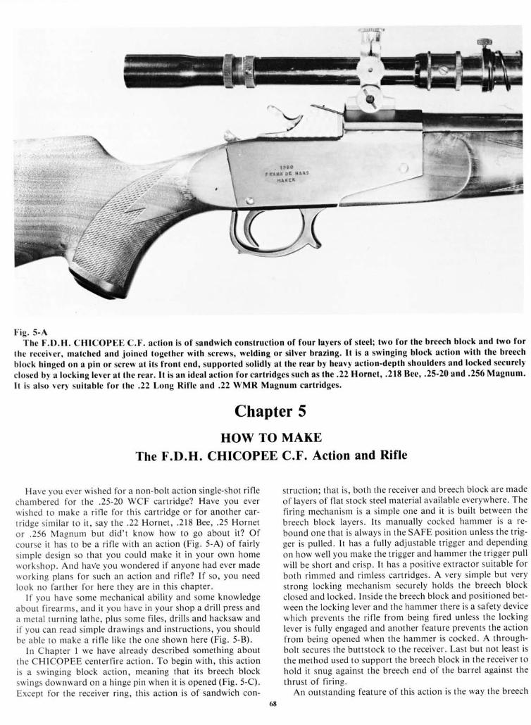
I ig . 5-AThc I.D.H. CHICOPEE C.F. action is of sandwich construction of four layers of steel; two for the breech block and two for
lhe receiver, matched and joined together with screws, welding or silver brazing. It is a swinging block action with the breech
block hinged on a pin or screw at its front end, supported solidly at the rear by heavy action-depth shoulders and locked securely
closed b1 a locking levcr at the rear. lt is an ideal action for cartridges such as the .22 Hornet, .2lE Bee, .25'20 and .256 Magnum.
I t is a lso very sui table for the .22Long Ri f le and.22 WMR Magnum car t r idges.
Chapter 5
HOW TO MAKEThe F.D.H. CHICOPEE C.F. Action and Rifle
Have you ever wished for a non-bol t act ion s ingle-shot r i f lechambered for the .25-20 WCF car t r idge? Have you everuished to make a r i f le for th is car t r idge or for another car-t r idge s imi lar to i t , say the .22 Hornet , .218 Bee, .25 Hornetor .256 Magnum but d id ' t know how to go about i t? Ofcourse i t has to be a r i f le wi th an act ion (F ig. 5-A) of fa i r lys imple design so that you could make i t in your own homeuorkshop. And haVe you wondered i f anyone had ever madeuork ing p lans for such an act ion and r i f le? I f so, you needlook no far ther for here they are in th is chapter .
l f you have some mechanical abi l i ty and some knowledgeabout f i rearms, and i t you have in your shop a dr i l l press anda metal turn ing la the, p lus some f i les, dr i l ls and hacksaw andi f you can read s imple drawings and inst ruct ions, you shouldbe able to make a r i f le l ike the one shown here (F ig. 5-B) .
In Chapter I we have already described something aboutthe CHICOPEE center f i re act ion. To begin wi th, th is act ionis a swinging b lock act ion, meaning that i ts breech b lockswings downward on a h inge p in when i t is opened (Fig. 5-C).Except for the receiver ring, this action is of sandwich con-
st ruct ion: that is . both the receiver and breech b lock are madeof layers of f lat stock steel meterial available everywhere. The
f i r ing mechanism is a s imple one and i t is bui l t between the
breech block layers. lts manually cocked hammer is a re-
bound one that is a lways in the SAFE posi t ion unless the t r ig-ger is pulled. It has a fully adjustable trigger and depending
on how wel l you make the t r igger and hammer the t r igger pul l
wi l l be shor t and cr isp. I t has a posi t ive extractor su i table for
both rimmed and rimless cartridges. A very simple but very
st rong lock ing mechanism securely holds the breech b lockclosed and locked. Ins ide the breech b lock and posi t ioned bet-rveen the locking lever and the hammer there is a safety devicewhich prevents the rif le from being fired unless the lockinglever is fully engaged and another feature prevents the actionfrom being opened when the hammer is cocked. A through-bol t secures the but ts tock to the receiver . Last but not least isthe method used to support the breech block in the receiver tohold it snug against the breech end of the barrel against thethrust of f i r ing.
An outstanding feature of th is act ion is the way the breech6tt
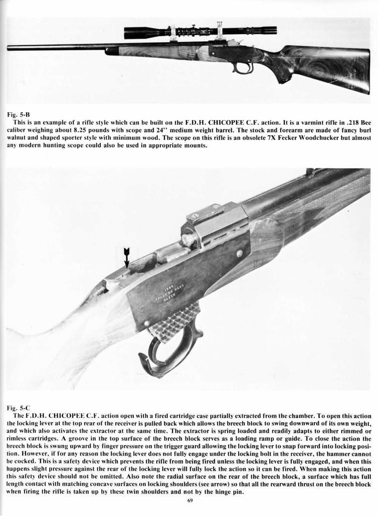
Fig. 5-BThis is an example of a rif le style which can be built on the F.D.H. CHICOPEE C.F. action. It is a varmint rif le in .21E Bee
caliber weighing about E.25 pounds with scope and 24" medium weight barrel. The stock and forearm are made of fancy burlwalnul and shaped sportcr style with minimum wood. The scope on this rif le is an obsolete 7X Fecker Woodchucker but almostanl modern hunting scope could also be used in appropriate mounts.
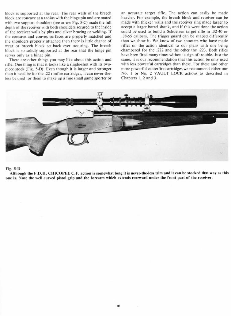
Fig. 5-CThe F.D.H. CHICOPEE C.F. action open with a fired cartridge case partially extracted from the chamber. To open this action
the locking lever at the top rear of lhe receiver is pulled back which allows the breech block to swing downward of its own weight,and which also activates the extractor at the same time. The extractor is spring loaded and readily adapts to either rimmed orrimless cartridges. A groove in the top surface of the breech block serves as a loading ramp or guide. To close the action thebreech block is swung upward by finger pressure on the trigger guard allowing the locking lever to snap forward into locking posi-tion. However, if for an!' reason the locking lever does not fully engage under the locking bolt in the receiver, the hammer cannotbe cocked. This is a safetl device which prevents the rif le from being fired unless the locking lever is fully engaged, and when thishappens slight pressure against the rear of the locking lever wil l fully lock the action so it can be fired. When making this actionthis safetl device should not be omitted. Also note the radial surface on the rear of the breech block. a surface which has fulllength contact with matching concave surfaces on locking shoulders (see arrow) so that all the rearward thrust on the breech blockwhen fir ing the rif le is taken up by these twin shoulders and not by the hinge pin.
69
block is supported at the rear. The rear walls of the breechblock are concave at a radius with the hinge pin and are matedwith two support shoulders (see arrow Fig. 5-C) made the fulldepth of the receiver with both shoulders secured to the insideof the receiver walls by pins and silver brazing or welding. Ifthe concave and convex surfaces are properly matched andthe shoulders properly attached then there is l i tt le chance ofwear or breech block set-back ever occuring. The breechblock is so solidly supported at the rear that the hinge pinserves only as a h inge p in.
There are other things you may like about this action andrif le. One thing is that it looks l ike a single-shot with its two-piece stock (Fig. 5-D). Even though it is larger and strongerthan it need be for the .22 rimfire cartridges, it can never-the-less be used for them to make up a fine small game sporter or
an accurate target rif le. The action can easily be madeheavier. For example, the breech block and receiver can bemade with thicker walls and the receiver ring made larger toaccept a larger barrel shank, and if this were done the actioncould be used to build a Schuetzen target rif le in .32-40 or.38-55 calibers. The trigger guard can be shaped differentlythan we show it. We know of two shooters who have maderif les on the action identical to our plans with one beingchambered for the .222 and the other the .223. Both rif leshave been fired many times without a sign of trouble. Just thesame, it is our recommendation that this action be only usedwith less powerful cartridges than these. For these and othermore powerful centerfire cartridges we recommend either ourNo. I or No. 2 VAULT LOCK actions as described inChapters l , 2 and 3.
Fig. 5-DAlthough the F.D.H. CHICOPEE C.F. action is somewhat long it is never-the-less trim and it can be stocked that way as this
one is. Note the well curved pistol grip and the forearm which extends rearward under the front part of the receiver.
70
CAPI ' IONS for drawings and photos wi th some pre l iminar l inst ruct ions for making the F.D.H. CHICOPEE C.F. act ion.
\O' t t - : AI I the dra* ings cxcept F ig. 5- l are madc actual s ize and any d imensions not g iven can be taken f rom the drawings.
a b,'
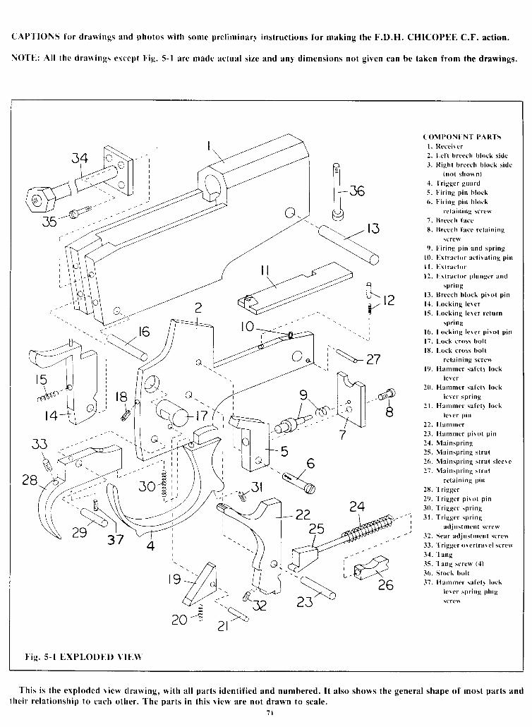
( 0MP0N} -NT PARTSl. Reccir cr2 . Lc f t b r ccch b l ock s i de3 . R igh l b r cce h b l ock s i d t
( no l shown)4 . ' l ' r i ggc r gua rd
5. l " i r ing pin bkrck6. l ' i r ing pin b lock
rc(ain ing screrv7. l l recch faccE. l l rccch facr : rcta in ing
scros9 . l i r i ng p i n and sp r i ng
10 . E r t r a r t o r a ( l i ! a t i ng p i n
I t . l . x t r ac tu r12 . l . r l r ae to r p l unge r and
sPr i n g
13. l l rcech bkrck pi ro l p in
14 . Lock ing l c re r15 . l , ock i ng l c r c r r c l u rn
sp r i ng16 . l , uck i ng l e r c r p i r o t p i n
17 . l . ock c ross bo l tl lJ . l ,ock cross bol l
rc la in ing scrcw19. Harnmcr safc l l lock
lcr cr20. Hamnter sa[ct1 lock
l e r c r sp r i ng21. l lanrntcr safct l krck
l e r c r p i n
22. [ Ianrnrer23 . Hammcr p i \ o t p i n
24 . Ma insp r i ng25 . Ma insp r i ng s t r u t26 . Ma insp r i ng s l r u t s l oc \o27 . Ma insp r i ng s t r u t
r r t a i n i ng p i n
2 l i . ' [ r i ggc r29 . l r i ggc r p i r o l p i n
30. ' l
r iggcr spr ing31 . I ' r i ggc r sp r i ng
adjus(mcnt screu32. Scar adjustnrcnt scrc*33. I r iggcr orcr t rarc l scrcr3 '1. l ang35. Tang screu ( .1)
36. Slock bol t37. I lanrmcr safet l lock
l c re r sp r i ng p l ug
sc rcF
_--- ,,16
\ \ -\- 27
t8b
t ' ie . 5- l EXPt,Ol) [ .D VIE\ \
frI s,q
l"ll 4s-ll 87
- ' II
JOG
56'a<
re22
25
This is the exploded v iew drawing,thei r re lat ionship 1o cach other . The
with all parts identif ied and numbered. It also shows lhe general shape of most parts andparts in th is v iew are not drawn to scale.
1 l