mrq1 field faulure relay - ing-fournais.dk · 6.4 secondary injection test ... venting damage due...
TRANSCRIPT

MRQ1 - Field faulure relay

2 TB MRQ1 02.97 E
1. Introduction
2. Features and characteristics
3. Design3.1 Connections3.1.1 Analog input circuits3.1.2 Blocking input3.1.3 External reset3.1.4 Output relays3.2 Display3.3 LEDs
4. Working principle4.1 Analog circuits4.2 Digital circuits4.3 Underimpedance measurement4.3 Undervoltage measurement
5. Operation and setting5.1 Adjustable Parameter5.2 Setting procedure5.2.1 Set point for the undervoltage element (U<)5.2.2 Trip delay for the undervoltage element (tU<)5.2.3 Impedance characteristic 1 (Z1A/Z1B)5.2.4 Trip delay for impedance
characteristic 1 (tZ1)5.2.5 Impedance characteristic 2 (Z2A/Z2B)5.2.6 Trip delay for impedance
characteristic 2 (tZ2)5.2.7 Slave address for remote control5.3 Determination of the setting values5.3.1 Underimpedance protection5.3.2 Undervoltage protection5.3.3 Setting example5.4 Indication and measuring values5.5 Reset
6. Relay testing andcommissioning6.1 Power-On6.2 Testing the output relays6.3 Checking the set values6.4 Secondary injection test6.4.1 Test equipment6.4.2 Example of test circuit for MRQ1 relay6.4.3 Checking the input circuits and
measured values6.4.4 Checking the operating and resetting
values of the undervoltage functions6.4.5 Checking the relay operating time of the
undervoltage function6.4.6 Checking the underimpedance
characteristics6.5 Checking the extern blocking and
reset functions6.6 Primary injection test6.7 Maintenance
7. Technical data7.1 Measuring inputs7.2 Common data7.3 Setting ranges and steps7.4 Common data for all MR relays
8. Order form
Important: For additional common data of all MRrelays please refer to manual �MR- DigitalMultifunctional Relays�
TB MRQ1 02.97 E 3
1. Introduction and application
The field failure relay MRQ1 protects synchronousgenerators against operation outside the stable opera-tion area due to loss of exitation. When partial orcomplete loss of excitation occurs on a synchronousmachine, reactive power flows from the system intothe machine and the apparent impedance as viewedfrom the machine terminals goes into the negative Xregion in the R-X diagram.The MRQ1 detects the low or under impedance con-dition and trips the generator circuit breaker, thus pre-venting damage due to out of step operation and sys-tem instability.
The under impedance measurement provides twoelements with separate impedance and time settings.Therefore setting according to the dynamic andsteady state stability curve is possible.
MRQ1 calculates the momentary impedance valuefrom the generator current and voltage and comparesthis value with the two settings of the under imped-ance elements.
Under impedance circle no. 1 reproduces the steadystate stability area of the generator. Element no. 1may be used for alarm purposes and correctivemeasures like boost excitation.
Element no. 2 reproduces the dynamic stability areaof the generator. The time delay is set to a lowervalue. It provides fast clearing on complete loss offield and backs up element no. 1. Element no. 2should trip the generator circuit breaker quickly.
The following factors determine the setting of the twoelements: Stability diagram of the generator, excita-tion system of the generator and the system configura-tion.
2. Features and characteristics
• Digital protection relay with powerful microcontrol-ler
• Three phase voltage supervision in delta-connection
• Current measurement in phase L1• Alphanumeric display for easy setting of the pro-
tection relay, reading of measured and calculatedvalues and read out of the fault memory
• Digital filtering of the measured values by use ofdiscrete Fourier analysis to suppress higher har-monics and d.c. components induced by faults orsystem operations
• Optimum adaptation to the stability characteristicof synchronous machines by two under imped-ance elements with separate set points and timedelays
• Indication of the impedance measurement: abso-lute, real and imaginary value
• Under voltage blocking (<10% Un) of the underimpedance elements to prevent maloperation dueto missing measuring voltage, e.g. fuse failure ornear by short circuit of the generator
• Self adjusting sample frequency for precise opera-tion between 40 Hz and 70 Hz
• External blocking and reset inputs• Communication via serial interface RS485• Five output relays:
Trip relay: Underimpedance elements 1 and 2Alarm relay: Underimpedance element 1Alarm relay: Underimpedance element 2Trip relay: undervoltageSelf supervision

4 TB MRQ1 02.97 E
3. Design
3.1 Connections
Fig. 3.1: Connection diagram
* Hint:The current transformer in phase 1 can also be connected to the outgoing line of the generator.
3.1.1 Analog input circuits
The MRQ1 receives the analog input signal of phasecurrent L1 (B3-B4) and the line to line voltages U12(A3/A4), U23 (A5/A6), U31 (A7/A8). The undervoltage element measures all three line-to-line volt-ages, whereas the under impedance elements usevoltage U23 and phase current L1 for the impedancecalculation.
3.1.2 Blocking input
Connection of the auxiliary voltage to the blockinginput D8/E8 inhibits all protective functions of theMRQ1. This may be used during start up of thegenerator.
3.1.3 External reset
Please refer to 5.5
TB MRQ1 02.97 E 5
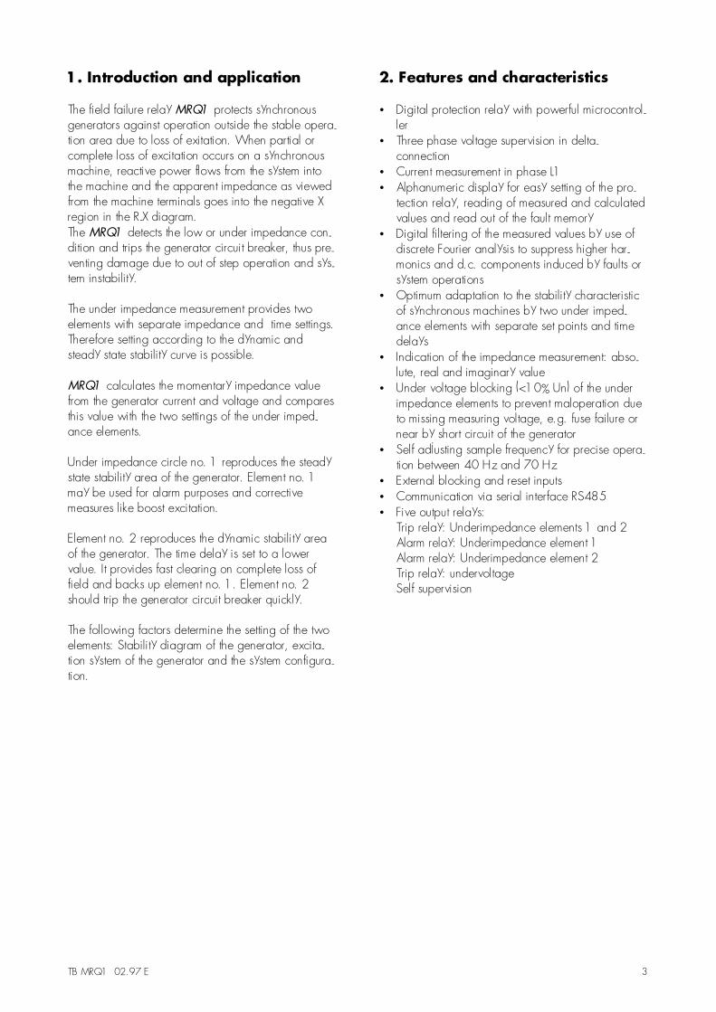
3.1.4 Output relays
The MRQ1 has five output relays with followingassigned functions:• Trip relay: underimpedance elements 1 and 2
(two change over contacts: C1, D1, E1;C2, D2, E2)
• Alarm relay: underimpedance element 1(one change over contact, C4, D4, E4)
• Alarm relay: underimpedance element 2(one change over contact, C5, D5, E5)
• Trip relay: undervoltage U<(one change over contact, C6, D6, E6)
• Self-supervision alarm relay(one change over contact, C7, D7, E7)
All trip and alarm relays are working current relays,the relay for self supervision is an idle current relay.
Fig. 3.2: Front plate MRQ1
The LED marked with letters RS lights up during settingof the slave address of the device for serial datacommunication.
6 TB MRQ1 02.97 E
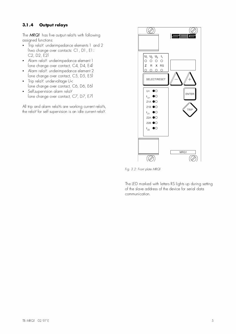
3.2 Display
Function Display shows Pressed pushbutton Corresponding LEDNormal operation |SEGMeasured operating valuesline-to-line voltagephase currentimpedance
Actual measuredvoltage U12, U23, U31
current L1impedance Z, R, X
<SELECT/RESET>one time for each value
U1, U2, U3,I1Z, R, X
Setting values:undervoltage setting value in volt <SELECT/RESET> <+> <-> U<trip delay undervoltage setting value in seconds <SELECT/RESET> <+> <-> tU<
Impedance setting Z1A setting value in % <SELECT/RESET> <+> <-> Z1AImpedance setting Z1B setting value in % <SELECT/RESET> <+> <-> Z1Btrip delay impedance Z1 setting value in seconds <SELECT/RESET> <+> <-> tZ1
Impedance setting Z2A setting value in % <SELECT/RESET> <+> <-> Z2AImpedance setting Z2B setting value in % <SELECT/RESET> <+> <-> Z2Btrip delay impedance Z2 setting value in seconds <SELECT/RESET> <+> <-> tZ2
Function blockade EXIT <+> until max. setting value LED of blocked parameterSlave address of serialinterface 1-32 <SELECT/RESET> <+><-> RSRecorded fault dataline-to-line voltages, current,impedance
Measured values in theinstant of tripping
<SELECT/RESET>one time for each value
U1, U2, U3, I1,Z, R, X
measuring range overflow max <SELECT/RESET> Z, R, Xblocked impedancemeasurement
? <SELECT/RESET>one time for each value
Z, R, X
Save parameter? SAV? <ENTER>Save parameters ! SAV! <ENTER> for about 3 sSoftware version First parrt (e.g. D16-)
Sec. part (e.g.5.01)<TRIP>one time for each part
Manual trip TRI? <TRIP>three times
Inquire password PSW? <SELECT/RESET>/<+>/<->/<ENTER>
Relay tripped TRIP <TRIP>or after fault tripping
U1, U2, U3, Z, U<, Z1A,Z1B, Z2A, Z2B
Secret password input XXXX <SELECT/RESET>/<+>/<->/<ENTER>
System reset |SEG <SELECT/RESET>for about 3 s
Table 3.1: Possible indication messages on the display
TB MRQ1 02.97 E 7
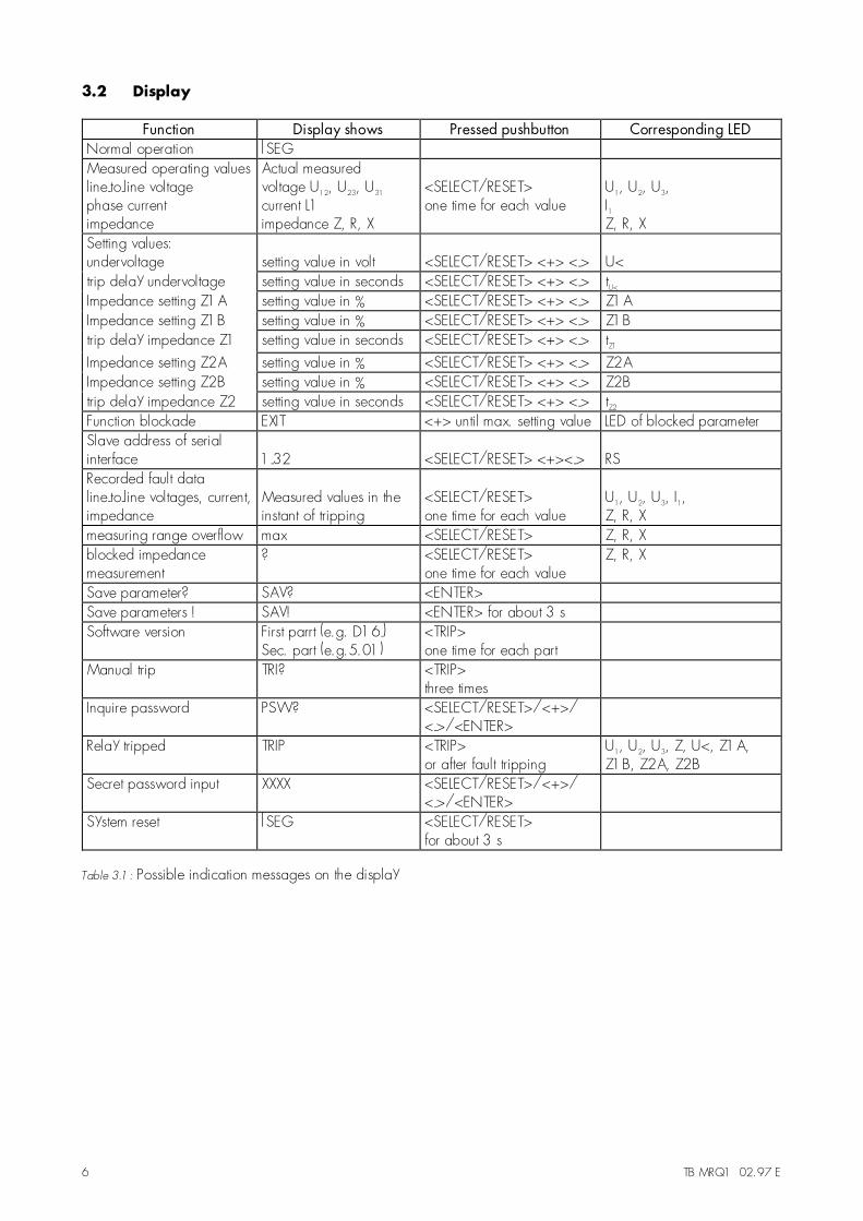
3.3 LEDs
LED-designation Colour Mode MeaningU1, U2, U3 green steady Display of the actual voltage
measuring valuesU1, U2, U3 red steady U< tripped
U1, U2, U3 red flashing U< picked up
I1 green steady Display of the actual currentmeasuring value
Z green steady Display of the actual imped-ance measuring absolute value
Z red steady Z< trippedZ red flashing Z< picked upR, X yellow steady Display of the actual imped-
ance measuring real andimaginary value
RS yellow steady Slave-address setting
U< green steady U<-setting
U< red steady U< tripped
U< red flashing U< picked up
tU< green steady tU<-setting
Z1A, Z1B green steady Z1<-setting
Z1A, Z1B red steady Z1< tripped
Z1A, Z1B red flashing Z1< picked up
tZ1 green steady tZ1-setting
Z2A, Z2B green steady Z2<-setting
Z2A, Z2B red steady Z2< tripped
Z2A, Z2B red flashing Z2< picked up
tZ2 green steady tZ2-setting
Table 3.2: Possible LED indications
4. Working principle
4.1 Analog circuit
The secondary current and voltage from the main cur-rent and voltage transformers are converted into pro-portional voltage signals via the input transformers.High frequency disturbances are suppressed by ana-log RC-filters.
The analog voltage signals are fed via sample andhold circuits to the A/D-converter of the microproces-sor and transformed to digital signals. The analogsignals are sampled with a self adjusting sample rateof 16 times of the system frequency. The precision ofthe impedance measurement is, therefore, independ-ent of variations of the system frequency in a range of40 Hz to 70 Hz.
4.2 Digital circuit
The essential part of the MRQ1 is a powerful micro-controller. All of the operations, from the analog todigital conversion up to the relay´s trip decision, arecarried out by the microcontroller digitally.The relay program is located in an EPROM (Read-only-memory). With this program the microcontrollerprocesses the analog signals and calculates the fun-damental wave form of voltages and current. The al-gorithm uses the �Fourier-notch� filter, excluding allfrequencies except the fundamental.
8 TB MRQ1 02.97 E
4.3 Underimpedance measurement
The underimpedance elements evaluate the phasecurrent L1 and the line to line voltage U23. The DFFTalgorithm calculates the real- and imaginary values ofvoltage and current:
Re[]: real partIm[]: imaginary part
[ ] [ ]
[ ] [ ]
U = Re U j Im U
I = Re I j Im I
23 23 23
1 1 1
+
+
The real and imaginary values of impedance are cal-culated as follows:
[ ] [ ] [ ] [ ][ ][ ] [ ][ ]
[ ] [ ] [ ] [ ][ ][ ] [ ][ ]
R* = Re U Re I Im U Im I
Re I Im I
X* = Im U Re I Re U Im I
Re I Im I
23 1 23 1
1
2
1
2
23 1 23 1
1
2
1
2
⋅ + ⋅
+
⋅ − ⋅
+
After an angle correction follows the actual imped-ance phasor:
Z = R+ j X = Z* e = j (R*+ j X*)j2⋅π
whereby:
R = - X*
X = + R*
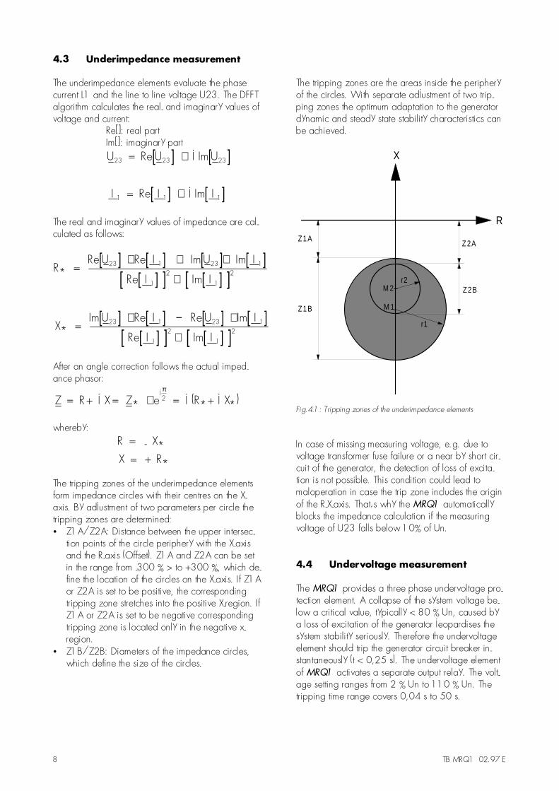
The tripping zones of the underimpedance elementsform impedance circles with their centres on the X-axis. By adjustment of two parameters per circle thetripping zones are determined:• Z1A/Z2A: Distance between the upper intersec-
tion points of the circle periphery with the X-axisand the R-axis (Offset). Z1A and Z2A can be setin the range from -300 % > to +300 %, which de-fine the location of the circles on the X-axis. If Z1Aor Z2A is set to be positive, the correspondingtripping zone stretches into the positive X-region. IfZ1A or Z2A is set to be negative correspondingtripping zone is located only in the negative x-region.
• Z1B/Z2B: Diameters of the impedance circles,which define the size of the circles.
The tripping zones are the areas inside the peripheryof the circles. With separate adjustment of two trip-ping zones the optimum adaptation to the generatordynamic and steady state stability characteristics canbe achieved.
X
R
Z2B
Z2AZ1A
Z1B
r2
r1
M 2
M 1
Fig.4.1: Tripping zones of the underimpedance elements
In case of missing measuring voltage, e.g. due tovoltage transformer fuse failure or a near by short cir-cuit of the generator, the detection of loss of excita-tion is not possible. This condition could lead tomaloperation in case the trip zone includes the originof the R-X-axis. That´s why the MRQ1 automaticallyblocks the impedance calculation if the measuringvoltage of U23 falls below 10% of Un.
4.4 Undervoltage measurement
The MRQ1 provides a three phase undervoltage pro-tection element. A collapse of the system voltage be-low a critical value, typically < 80 % Un, caused bya loss of excitation of the generator jeopardises thesystem stability seriously. Therefore the undervoltageelement should trip the generator circuit breaker in-stantaneously (t < 0,25 s). The undervoltage elementof MRQ1 activates a separate output relay. The volt-age setting ranges from 2 % Un to 110 % Un. Thetripping time range covers 0,04 s to 50 s.
TB MRQ1 02.97 E 9
5. Operation and setting
5.1 Adjustable parameter
The user has access to the parameters listed below:
U< - Set point of the undervoltage elementtU< - Trip delay of the undervoltage elementZ1A - Offset value of impedance circle no. 1Z1B - Diameter of impedance circle no. 1tZ1 - Trip delay of impedance element no. 1Z2A - Offset value of impedance circle no. 2Z2B - Diameter of impedance circle no. 2tZ2 - Trip delay time of impedance element no. 2RS - Slave address for remote control
5.2 Setting procedure
For parameter setting a password has to be enteredfirst. (Please refer to 4.4 of description �MR - Digitalmultifunctional relays�).
5.2.1 Set point for the undervoltageelement (U<)
During setting of the undervoltage set point U< thedisplay shows the actual setting in Volts. The set pointmay be altered by use of the buttons <+> and <->and stored with <ENTER>. The undervoltage elementis blocked, if the parameter is set to �EXIT�.
5.2.2 Trip delay time delay for theundervoltage element (tU<)
During setting of the undervoltage trip delay tU< thedisplay shows the actual setting in seconds. The tripdelay may be altered by use of the buttons <+> and<-> and stored with <ENTER>. If this parameter is setto �EXIT�, the undervoltage output relay is blocked(infinite tripping time). The measurement and displayfor the undervoltage element is still active.
5.2.3 Impedance characteristic 1(Z1A/Z1B)
The two impedance tripping zones of the MRQ1 formcircles in the R-X diagram. The centre of the circles islocated along the X-axis. Circle no. 1 is described bytwo parameters: Z1A, the distance of the circle fromthe R-axis and Z1B, the diameter of the circle(ref. 4.3).
The two parameters Z1A and Z1B are expressed asper cent value of the calculated "nominal impedance"ZN of the individual MRQ1-relay. ZN is defined as fol-low:
ZU
3 IN
N,MRQ
N,MRQ
=⋅
.
During setting of the offset value Z1A the displayshows the per cent value. This value may be alteredby use of the buttons <+> and <-> in the range from-300 % to + 300 % and stored with <ENTER>. Withnegative values the circle lies completely in the nega-tive X region. Positive values shift the circle into thepositive X-region. Zero means that the periphery of thecircle touches the R-axis with the circle in the negativeregion.The diameter of the circle Z1B may be set in therange from 0 % to 600 %. If Z1B is set to zero, thisimpedance element is blocked.
5.2.4 Trip delay for impedancecharacteristic 1 (tZ1)
During setting of tripping time tZ1 for impedance ele-ment no.1 the display shows the actual setting in sec-onds. The tripping time may be altered by use of thebuttons <+> and <-> and stored with <ENTER>.
5.2.5 Impedance characteristic 2Z2A/Z2B)
The setting of Z2A and Z2B is similar to the setting ofZ1A and Z1B. Please refer to 5.2.3.
5.2.6 Trip delay for impedancecharacteristic 2 (tZ2)
During setting of tripping time tZ2 for impedance ele-ment no. 2 the display shows the actual setting inseconds. The tripping time may be altered by use ofthe buttons <+> and <-> and stored with <ENTER>.
5.2.7 Slave address for remote control
The slave address may be altered by use of the but-tons <+> and <-> and stored with <ENTER>.
10 TB MRQ1 02.97 E
5.3 Determination of the setting value
5.3.1 Underimpendance protection
Calculation of the setting values for the impedancetripping zones:
The settings of the impedance tripping zones haveto be determined by the generator reactances X´d andXd, the transformer reactance XT and the grid imped-ance XN.
Knowing the above listed parameters, the secondarypercentage setting values may be calculated from:
x (%) x (p.u.) I I U U
I I U U100(%)sec prim
N,MRQ N,CT,prim N,VT,sec N,Gen
N,CT,sec N,Gen N,MRQ N,VT,prim
= ⋅⋅ ⋅ ⋅
⋅ ⋅ ⋅⋅
Definitions:
xsec(%) - calculated secondary impedance setting ofMRQ1 (Z1A, Z1B, Z2A or Z2B) in percentage
xprim(p.u.) -primary reactance of generator (Xd´ andXd), transformer (XT) and grid (XN) in per unit
UN,Gen - Generator nominal voltage in VIN,Gen - Generator nominal current in AUN,VT,prim - Primary nominal voltage of the voltage
transformer in VUN,VT,sec - Secondary nominal voltage of the
voltage transformer in VIN,CT,prim - Primary nominal current of the current
transformer in AIN,CT,sec - Secondary nominal current of the current
transformer in AUN,MRQ - Nominal voltage of the MRQ1 in V
(100V / 230V / 400V)IN,MRQ - Rated current of the MRQ1 in A
(1A/5A)
or:
x (%) x (p.u.) K U I
K I U100(%)sec prim
I N,Gen N,MRQ
U N,Gen N,MRQ
= ⋅⋅ ⋅⋅ ⋅
⋅
With the current and voltage transfer ratios:KI : for currentKu : for voltage
K I
II
N,CT,prim
N,CT,sec
= und K U
UU
N,VT,prim
N,VT,sec
=
Tripping time settings for the underimpedanceelements:
The underimpedance protection element no.1 isusally adapted to the steady state stability characteris-tic of the generator. Generally, it takes at least 2 to 6seconds to lose synchronism in case of partial loss ofexcitation. Hence the tripping time may be set from0,5 s to 3 s.
The second underimpedance element provides fastclearing on loss of field and is adapted to thedynamic stability characteristic of the generator. Thiselement should be used instantaneously or with shortdelay of 0,25 s to 0,5 s.

TB MRQ1 02.97 E 11
The diagrams below show examples for the relay setting:
Fig. 5.1: Setting adapted to the steady state and dynamic stability characteristic
Fig. 5.2: Selective protection with any generator load

12 TB MRQ1 02.97 E
5.3.2 Undervoltage protection
The undervoltage protection element is usually set tothe critical system voltage value at which the genera-tor with loss of field jeopardises the system stability.The limit is normally about 80 % of the nominal gen-erator voltage. The secondary set value is calculatedas follows:
U 0,8U
KN,Gen
U
= ⋅
The undervoltage trip delay should be set at0,25 s to max. 1 s.
5.3.3 Setting example
The example below explains the setting procedure fora synchronous generator of 200 MW:
Generator parameters:
PGen = 200 MWCOSϕ = 0.85UN,Gen = 15.75 kVIN,Gen = 8625 Axd = 1.9808x�d = 0.2428xN = 0.2KU = 15750 V/100 VKI = 12000 A/5 AUN,MRQ = 100 VIN,MRQ = 5 A
Setting of the impedance element no. 1 (steady statestability characteristic):
Z (%) xK U I
K I U100 (%)1A N
I N,Gen N,MRQ
U N,Gen N,MRQ
= ⋅⋅ ⋅⋅ ⋅
⋅
Z 0.22400 15750 5
157.5 8625 100100 (%) 27.8 %1A = ⋅ ⋅ ⋅
⋅ ⋅⋅ =
Z 28 %1A ≈
Z (%) xK U I
K I U100 (%) Z1B d
I N,Gen N,MRQ
U N,Gen N,MRQ1A= ⋅
⋅ ⋅⋅ ⋅
⋅ +
Z 1.98082400 15750 5
157.5 8625 100100 (%) 28 %1B = ⋅ ⋅ ⋅
⋅ ⋅⋅ +
Z 303.6 % 304 %1B = ≈
Setting of the impedance element no. 2(dynamic stability characteristic):
Z (%)1
2x'
K U I
K I U100 (%)2A d
I N,Gen N,MRQ
U N,Gen N,MRQ
= − ⋅⋅ ⋅⋅ ⋅
⋅
Z1
20.2428
2400 15750 5
157.5 8625 100100 (%)2A = − ⋅ ⋅ ⋅
⋅ ⋅⋅
Z 16.9 % 17 %2A = − ≈ −
Z (%) xK U I
K I U100 (%) Z2B d
I N,Gen N,MRQ
U N,Gen N,MRQ2A= ⋅
⋅ ⋅⋅ ⋅
⋅ +
Z 1.98082400 15750 5
157,5 8625 100100 (%) 17 %2B = ⋅ ⋅ ⋅
⋅ ⋅⋅ −
Z 258.6 % 259 %2B = ≈
TB MRQ1 02.97 E 13
Setting of the trip delay for the impedance elements:
tZ1 = 1.0 stZ2 = 0.25 s
Setting of the undervoltage element:
U 0.8 UN,GenKU
0.8 15750
157.580 V= ⋅ = ⋅ =
Setting of the trip delay for the undervoltage element:
tU< = 0.25 s
5.4 Indication and measuring values
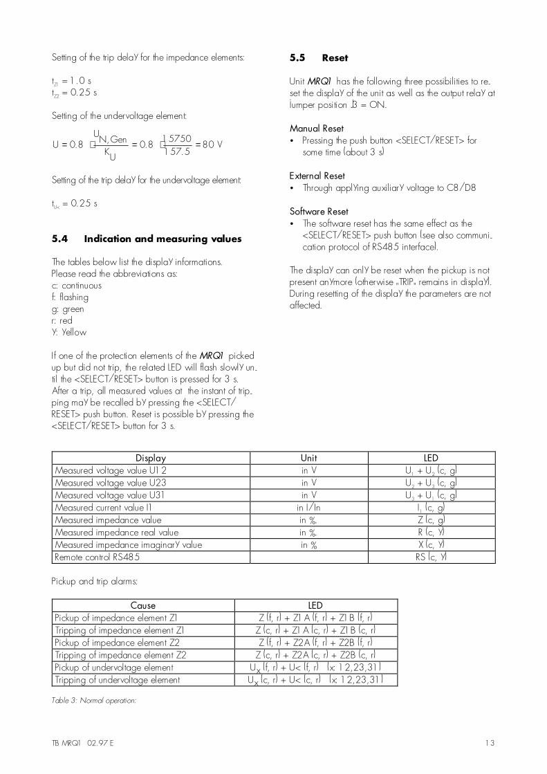
The tables below list the display informations.Please read the abbreviations as:c: continuousf: flashingg: greenr: redy: yellow
If one of the protection elements of the MRQ1 pickedup but did not trip, the related LED will flash slowly un-til the <SELECT/RESET> button is pressed for 3 s.After a trip, all measured values at the instant of trip-ping may be recalled by pressing the <SELECT/RESET> push button. Reset is possible by pressing the<SELECT/RESET> button for 3 s.
5.5 Reset
Unit MRQ1 has the following three possibilities to re-set the display of the unit as well as the output relay atjumper position J3 = ON.
Manual Reset• Pressing the push button <SELECT/RESET> for
some time (about 3 s)
External Reset• Through applying auxiliary voltage to C8/D8
Software Reset• The software reset has the same effect as the
<SELECT/RESET> push button (see also communi-cation protocol of RS485 interface).
The display can only be reset when the pickup is notpresent anymore (otherwise "TRIP" remains in display).During resetting of the display the parameters are notaffected.
Display Unit LEDMeasured voltage value U12 in V U1 + U2 (c, g)Measured voltage value U23 in V U2 + U3 (c, g)Measured voltage value U31 in V U3 + U1 (c, g)Measured current value I1 in I/In I1 (c, g)Measured impedance value in %. Z (c, g)Measured impedance real value in %. R (c, y)Measured impedance imaginary value in % X (c, y)Remote control RS485 RS (c, y)
Pickup and trip alarms:
Cause LEDPickup of impedance element Z1 Z (f, r) + Z1A (f, r) + Z1B (f, r)Tripping of impedance element Z1 Z (c, r) + Z1A (c, r) + Z1B (c, r)Pickup of impedance element Z2 Z (f, r) + Z2A (f, r) + Z2B (f, r)Tripping of impedance element Z2 Z (c, r) + Z2A (c, r) + Z2B (c, r)Pickup of undervoltage element Ux (f, r) + U< (f, r) (x: 12,23,31)Tripping of undervoltage element Ux (c, r) + U< (c, r) (x: 12,23,31)
Table 3: Normal operation:

14 TB MRQ1 02.97 E
6. Relay Testing andcommissioning
The test instructions following below help to verify theprotection relay performance before or during com-missioning of the protection system. To avoid a relaydamage and to ensure a correct relay operation, besure that:
the auxiliary power supply rating corresponds to theauxiliary voltage on site.• the rated current and rated voltage of the relay
correspond to the plant data on site.• the current transformer circuits and voltage trans-
former circuits are connected to the relay correctly.all signal circuits and output relay circuits are con-nected correctly.
6.1 Power-On
NOTE!Prior to switch on the auxiliary power supply, be surethat the auxiliary supply voltage corresponds with therated data on the type plate.Switch on the auxiliary power supply to the relay andcheck that the message "ISEG" appears on the dis-play and the self supervision alarm relay (watchdog)is energized (Contact terminals D7 and E7 closed).
6.2 Testing the output relays
NOTE!Prior to commencing this test, always block the outputcircuits or interrupt in another way the output circuitswhich can cause the tripping of the circuit breaker ifthe breaker operation during this test is not desired.
By pressing the push button <TRIP> once the displayshows you the first part of the software version of therelay (e.g. �D08-�). By pressing the push button<TRIP> twice the display shows the second part of thesoftware version of the relay (e.g. �4.01�). The soft-ware version should be quoted in all correspondence.After you have got a message "PSW?" on the displayby pressing the push button <TRIP> once more pleaseenter the correct password to proceed with the test.After that the message "TRI?" will follow. Confirm thistesting by means of pressing push button <TRIP>again.
All output relays should then be activated and the selfsupervision alarm relay (watchdog) should be deacti-vated one after another with a time interval of 1 sec-ond. Thereafter, reset all output relays back to theirnormal positions by pressing the push button<SELECT/RESET>.
6.3 Checking the set values
By repeatedly pressing the push button <SELECT> allrelay set values may be checked and set value modi-fication can be done with the push button <+><->and <ENTER>. For detailed information about that,please refer to chapter 5.
6.4 Secondary injection test
6.4.1 Test equipment
− Voltmeter, ammeter with class 1 or better− Phase angle meter− Auxiliary power supply with the voltage correspond-
ing to the rated data on the type plate− Single-phase current supply unit (adjustable from
0 to ≥ 10xIn)− Single-phase or three phase voltage supply unit with
phase shifting (adjustable from 0 to ≥ 1.2xUn)− Timer to measure the operating time
(Accuracy class ≤ ±10ms)− Switching device− Test leads and tools
6.4.2 Example of test circuit for MRQ1
relay
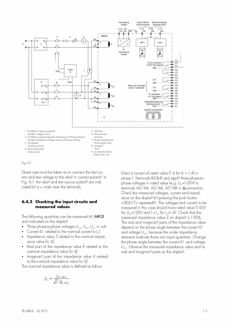
For testing field failure relays, you need both currentand voltage input signals with adjustable phase shift-ing. Figure 6.1 shows an example of a test circuitwith adjustable three-phase voltage source and a sin-gle-phase current source energizing the MRQ1 relayunder test. If you only have a single-phase voltagesource, you can also test the under impedancefunction of the MRQ1 by connecting the single phasevoltage to the relay terminals A5/A6.For testing the field failure relay, the input voltagesshall be applied to the relay with a constant valuewithin its effective range (e.g. U=50V). The inputcurrent and phase angle shall be appropriatelyvaried.
TB MRQ1 02.97 E 15
~=
MRQ1
VersorgungSupply
VersorgungSupply
L+/L L-/NC9 E9 D9
Extern ResetExternal Reset
BlockiereingangBlocking Input
L+/LC8
L-/ND8
L+/LE8
NGP
NGP
Serielle SchnittstelleSerial Interface
SelbstüberwachungSelfsupervision
Z2<
U< AuslösenU< Trip Signal
Z1<
Warnung / AnzeigeAlarm / Indication
Z1/Z2 AuslösenZ1/Z2 Trip Signal
D1C1E1
D2C2E2D4C4E4D5
D6
C5
C6
E5
E6
B3
I1
U
U
U
D7C7E7
~A
1
Timer8Start
-
+
Stop
+
3 4 6
5
A3
A4
A5
A6
A7
A8
B4
9
1. Einstellbare SpannungsquelleVariable voltage source
2. Einstellbare Spannungsquelle dreiphasig mit PhasenschieberVariable three-phase voltage source with phase shifting
3. SchaltgerätSwitching device
5. Voltmeter6. Amperemeter
Ammeter7. Phasenwinkelmesser
Phase angle meter8. Zeitgeber
Timer9. zu testendes Relais
Relay under Test
12
23
31
V
7 ϕ
2 3
L1
L2
L3
N
-
4. SerienwiderstandSeries resistor
*
*
**
*
*
*
*
Fig. 6.1
Great care must be taken as to connect the test cur-rent and test voltage to the relay in correct polarity. InFig. 6.1 the relay and test source polarity are indi-cated by a * mark near the terminals.
6.4.3 Checking the input circuits andmeasured values
The following quantities can be measured by MRQ1
and indicated on the display:• Three phase-to-phase voltages U12, U23, U31 in volt• Current IL1 related to the nominal current (x IN)• Impedance value Z related to the nominal imped-
ance value (in %)• Real part of the impedance value R related to the
nominal impedance value (in %)• Imaginary part of the impedance value X related
to the nominal impedance value (in %)The nominal impedance value is defined as follow:
NN,MRQ
N,MRQ
ZU
3 I=
⋅
Inject a current of rated value (1A for In = 1A) inphase 1 (terminals B3-B4) and apply three phase-to-phase voltages in rated value (e.g. UN=100V) toterminals A3/A4, A5/A6, A7/A8 in ∆-connection.Check the measured voltages, current and imped-ance on the display by pressing the push button<SELECT> repeatedly. The voltages and current to bemeasured in this case should have rated value (100Vfor UN=100V and 1x IN for IN=1A). Check that themeasured impedance value Z on display is 100%.The real and imaginary parts of the impedance valuedepend on the phase angle between the current IL1and voltage U23, because the under impedanceelements evaluate these two input quantities. Changethe phase angle between the current IL1 and voltageU23. Observe the measured impedance value and itsreal and imaginary parts on the display.
16 TB MRQ1 02.97 E
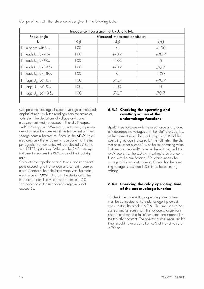
Compare them with the reference values given in the following table:
Impedance measurement at U=UN and I=INPhase angle Measured impedance on display
(°) Z(%) R(%) X(%)
IL1 in phase with U23 100 0 +100
IL1 leads U23 by 45° 100 +70.7 +70.7
IL1 leads U23 by 90° 100 +100 0
IL1 leads U23 by 135° 100 +70.7 -70.7
IL1 leads U23 by 180° 100 0 -100
IL1 lags U23 by 45° 100 -70.7 +70.7
IL1 lags U23 by 90° 100 -100 0
IL1 lags U23 by 135° 100 -70.7 -70.7
Compare the readings of current, voltage at indicateddisplay of relay with the readings from the ammeter,voltmeter. The deviations of voltage and currentmeasurement must not exceed 1% and 3% respec-tively. By using an RMS-metering instrument, a greaterdeviation may be observed if the test current and testvoltage contain harmonics. Because the MRQ1 relaymeasures only the fundamental component of the in-put signals, the harmonics will be rejected by the in-ternal DFFT-digital filter. Whereas the RMS-meteringinstrument measures the RMS-value of the input sig-nals.Calculate the impedance and its real and imaginaryparts according to the voltage and current measure-ment. Compare the calculated value with the meas-ured value on MRQ1 display. The deviation of theimpedance absolute value must not exceed 5%.The deviation of the impedance angle must notexceed 5°.
6.4.4 Checking the operating andresetting values of theundervoltage functions
Apply three voltages with the rated value and gradu-ally decrease the voltages until the relay picks up, i.e.at the moment when the LED U< lights up. Read theoperating voltage indicated by the voltmeter. The de-viation must not exceed 1% of the set operating value.Furthermore, gradually increase the voltages until therelay resets, i.e. the LED U< is extinguished (not con-fused with the dim flashing LED, which means thestorage of the last disturbance). Check that the reset-ting voltage is less than 1.03 times the operatingvoltage.
6.4.5 Checking the relay operating timeof the undervoltage function
To check the undervoltage operating time, a timermust be connected to the undervoltage trip outputrelay contact (terminals D6/E6). The timer should bestarted simultaneously with the voltage change fromsound condition to a faulty condition and stopped bythe trip relay contact. The operating time measured bytimer should have a deviation <3% of the set value or< 20 ms.
TB MRQ1 02.97 E 17
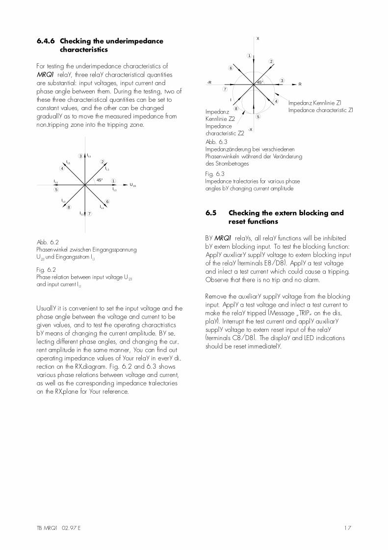
6.4.6 Checking the underimpedancecharacteristics
For testing the underimpedance characteristics ofMRQ1 relay, three relay characteristical quantitiesare substantial: input voltages, input current andphase angle between them. During the testing, two ofthese three characteristical quantities can be set toconstant values, and the other can be changedgradually as to move the measured impedance fromnon-tripping zone into the tripping zone.
45°
IL1
IL1
IL1
IL1
IL1
IL1
IL1
IL1
U23
1
23
4
5
8
7
6
Abb. 6.2Phasenwinkel zwischen EingangsspannungU und Eingangsstrom I23 L1
23
L1
Fig 6.2.Phase relation between input voltage Uand input current I
Usually it is convenient to set the input voltage and thephase angle between the voltage and current to begiven values, and to test the operating charactristicsby means of changing the current amplitude. By se-lecting different phase angles, and changing the cur-rent amplitude in the same manner, you can find outoperating impedance values of your relay in every di-rection on the RX-diagram. Fig. 6.2 and 6.3 showsvarious phase relations between voltage and current,as well as the corresponding impedance trajectorieson the RX-plane for your reference.
45°
-X
X
-R
I
R3
21
6
7
8
5
4
Abb 6.3.Impedanzänderung bei verschiedenenPhasenwinkeln während der Veränderungdes Strombetrages
Fig 6.3.Impedance trajectories for various phaseangles by changing current amplitude
Impedanz Kennlinie Z1Impedance characteristic Z1Impedanz
Kennlinie Z2Impedancecharacteristic Z2
6.5 Checking the extern blocking andreset functions
By MRQ1 relays, all relay functions will be inhibitedby extern blocking input. To test the blocking function:Apply auxiliary supply voltage to extern blocking inputof the relay (terminals E8/D8). Apply a test voltageand inject a test current which could cause a tripping.Observe that there is no trip and no alarm.
Remove the auxiliary supply voltage from the blockinginput. Apply a test voltage and inject a test current tomake the relay tripped (Message �TRIP� on the dis-play). Interrupt the test current and apply auxiliarysupply voltage to extern reset input of the relay(terminals C8/D8). The display and LED indicationsshould be reset immediately.

18 TB MRQ1 02.97 E
6.6 Primary injection test
Generally, a primary injection test could be carriedout in the similar manner as the secondary injectiontest above described, with the difference that theprotected power system should be, in this case, con-nected to the installed relays under test �on line�, andthe test currents and voltages should be injected to therelay through the current and voltage transformers withthe primary side energized. Since the cost and poten-tial hazards are very high for such a test, especially ifstaged fault tests are intended, primary injection testsare usually limited to very important protective relaysto the power system.Because of its powerful combined indicating andmeasuring functions, you have still the possibilities totest the MRQ1 relay in the manner of a primary injec-tion without extra expenditures and time consumption.In actual service, for example, the measured currentand voltage values on the display may be checkedphase by phase and compared with the current andvoltage indications of the ammeter and voltmeter. It isalso possible to check the measured generator im-pedance value and its real and imaginary parts,Please calculate the power factor of the operatinggenerator, and compare it with the power factormeter indication on the switch-board panel to verifythat your relay works and measures correctly and toverify that the relay is connected to the power systemwith the correct polarity.
6.7 Maintenance
Maintenance testing is generally done on site at regu-lar intervals. These intervals vary among users de-pending on many factors: e.g. the type of protectiverelays employed; the importance of the primaryequipment being protected; the user�s past experi-ence with the relay, etc.For electromechnical or static relays, maintenancetesting will be performed at least once a year accord-ing to the experiences. For digital relays like MRQ1,this interval can be substantially longer. This is be-cause that:• the MRQ1 relays are equipped with very wide
self-supervision functions, so that many faults in therelay can be detected and signalized during theservice. Important: The self-supervision output relaymust be connected to a central alarm panel!
• the combined measuring functions in MRQ1 relayenable supervision the relay functions duringservice.
• the combined TRIP test function of the MRQ1 relayallows to test the relay output circuits by powersystem interrupt.
A testing interval of two years for maintenance will,therefore, be recommended.During a maintenance testing, the relay functions in-cluding the operating values and relay tripping char-acteristics as well as the operating time should betested.
TB MRQ1 02.97 E 19
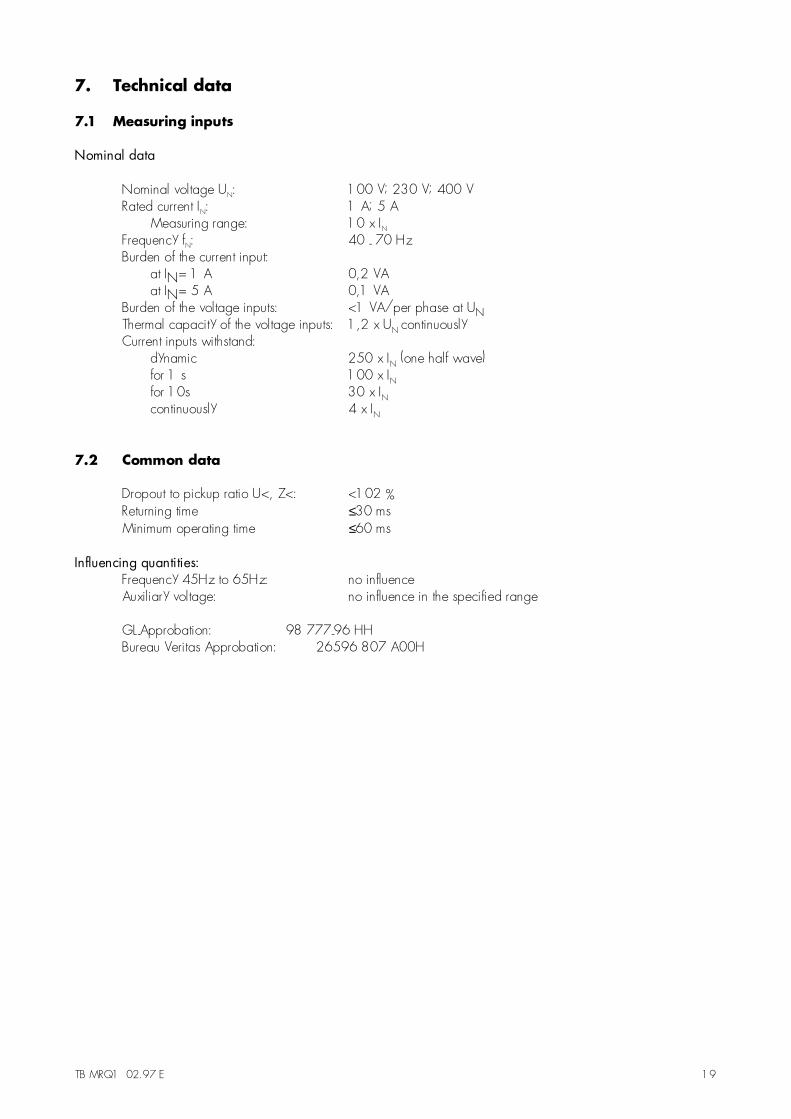
7. Technical data
7.1 Measuring inputs
Nominal data
Nominal voltage UN: 100 V; 230 V; 400 VRated current IN: 1 A; 5 A
Measuring range: 10 x INFrequency fN: 40 - 70 HzBurden of the current input:
at IN= 1 A 0,2 VAat IN= 5 A 0,1 VA
Burden of the voltage inputs: <1 VA/per phase at UNThermal capacity of the voltage inputs: 1,2 x UN continuouslyCurrent inputs withstand:
dynamic 250 x IN (one half wave)for 1 s 100 x INfor 10s 30 x INcontinuously 4 x IN
7.2 Common data
Dropout to pickup ratio U<, Z<: <102 %Returning time ≤30 msMinimum operating time ≤60 ms
Influencing quantities:Frequency 45Hz to 65Hz: no influenceAuxiliary voltage: no influence in the specified range
GL-Approbation: 98 777-96 HHBureau Veritas Approbation: 26596 807 A00H

20 TB MRQ1 02.97 E
7.3 Setting ranges and steps
Setting and displaying of voltage is made in Volts.Setting and displaying of current is related to the nomi-nal current IN of the MRQ1.Setting and displaying of the impedance values are re-lated to the nominal values of MRQ1 (pl. ref. to 4.3)
Z (%) =U
L2 - L3U
N
INIL1
100 (%)⋅ ⋅
Z (%) Z3I
U100 (%)Sek.
N
N
= ⋅
Z (%)Z
Z100 (%)Sek.
N
= ⋅
Element Parameter Setting range / steps Assigned TolerancesU< U<
tU<
EXIT; 2...110 V / 1V (UN = 100V)EXIT; 5...255 V / 1V (UN = 230V)EXIT; 10...440 V / 2V (UN = 400V)(EXIT blocks the function)
0.04...50s; EXIT /0.01; 0.02; 0.05; 0.1; 0.2; 0.5; 1.0; 2.0 s(EXIT: t = ∞)
± 1 % of set valueor < 0.3V whichever is larger
± 1 % or ± 20 ms whichever islarger
Z1 Z1AZ1B
tZ1
-300 ... 300 % of ZN / 1%0 ... 600 % of ZN / 1%(Z1B = 0 blocks the function)
0.04...50 s; EXIT /0.01; 0.02; 0.05; 0.1; 0.2; 0.5s(EXIT: t = ∞)
± 5 % of set value at nominal values
± 1 % or ± 20 ms whichever islarger
Z2 Z2AZ2B
tZ2
-300 ... 300 % of ZN / 1%0 ... 600 % of ZN / 1%(Z2B = 0 blocks the function)
0.04...50 s; EXIT /0.01; 0.02; 0.05; 0.1; 0.2; 0.5s(EXIT: t = ∞)
± 5 % of set value at nominal values
± 1 % or ± 20 ms whichever islarger
7.4 Common data for all MR relays
Please refer to manual �MR - Digital Multifunctional Relays�
TB MRQ1 02.97 E 21
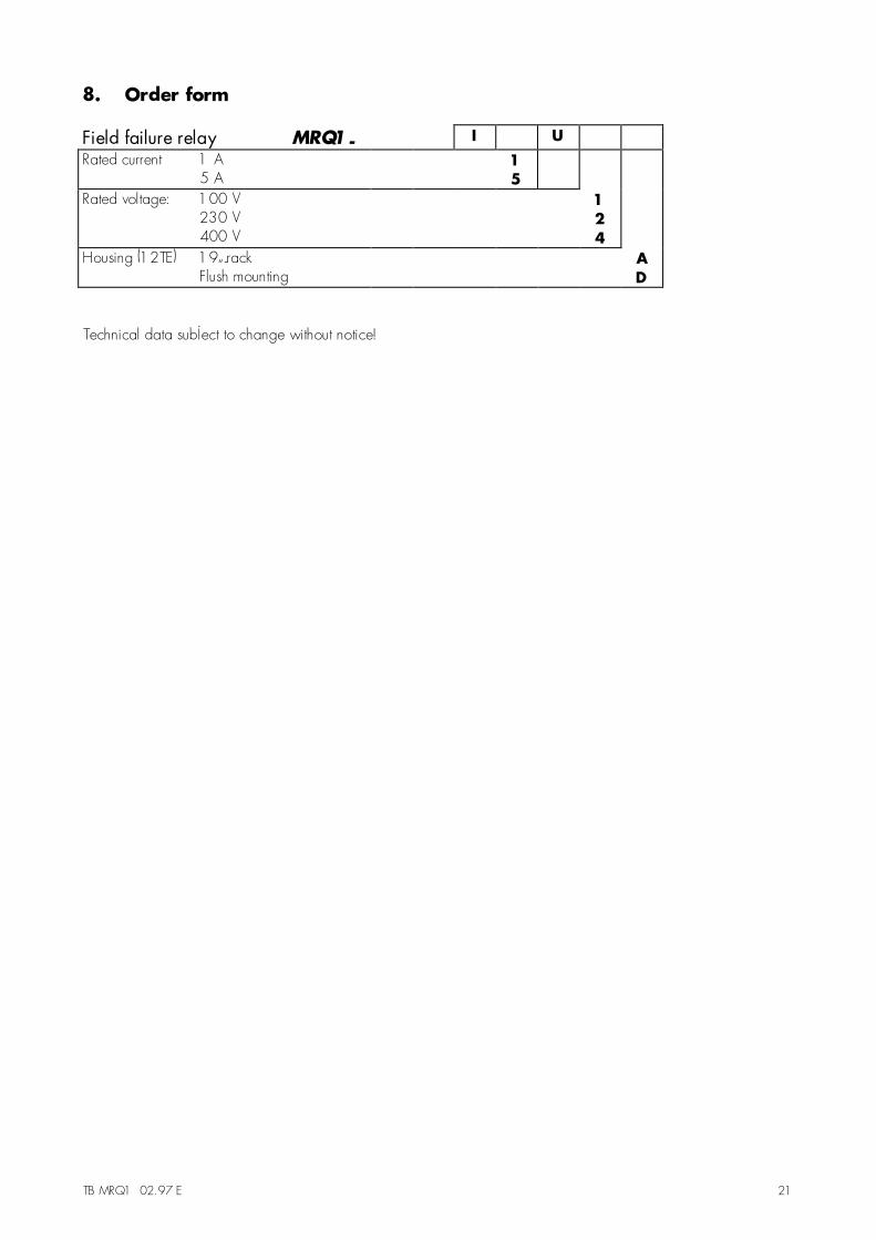
8. Order form
Field failure relay MRQ1- I U
Rated current 1 A5 A
15
Rated voltage: 100 V230 V400 V
124
Housing (12TE) 19�-rackFlush mounting
AD
Technical data subject to change without notice!

22 TB MRQ1 02.97 E
Setting list MRQ1
Project: SEG job.-no.:
Function group: = Location: + Relay code: -
Relay functions: Password:
Date:
Setting of parameters
Function UnitDefaultsettings
Actualsettings
U< Pickup of undervoltage element V 80/190/320*
tU< Tripping of undervoltage element s 0.5
Z1A Pickup of impedance element % 20
Z1B Voltage theshold for vector surge measuring % 100
tZ1 Tripping of impedance element Z1 s 1.00
Z2A Pickup of impedance element Z2A % - 10
Z2B Pickup of impedance element Z2B % 70
tZ1 Tripping of impedance element Z2 s 0.5
RS Slave address
* Thresholds dependent on rated voltage 100 V / 230 V / 400 V