ms-1756 disassembly guide - msi notebook · 2018-11-23 · ge70 (ms-1756) disassembly guide...
TRANSCRIPT
GE70 (MS-1756) Disassembly Guide
■ 1、BATTERY PACK
■ 2、BOTTOM DOOR ASSY
■ 3、HDD MODULE
■ 4、THERMAL-KIT、CPU、DRAM AND WIRELESS
■ 5、ODD MODULE
■ 6、SEPARATE UPPER CASE AND LOWER CASE
■ 7、LOWER CASE ASSY
■ 8、UPPER CASE ASSY
■ 9、LCD MODULE ASSY
GE70 (MS-1756) Disassembly Guide
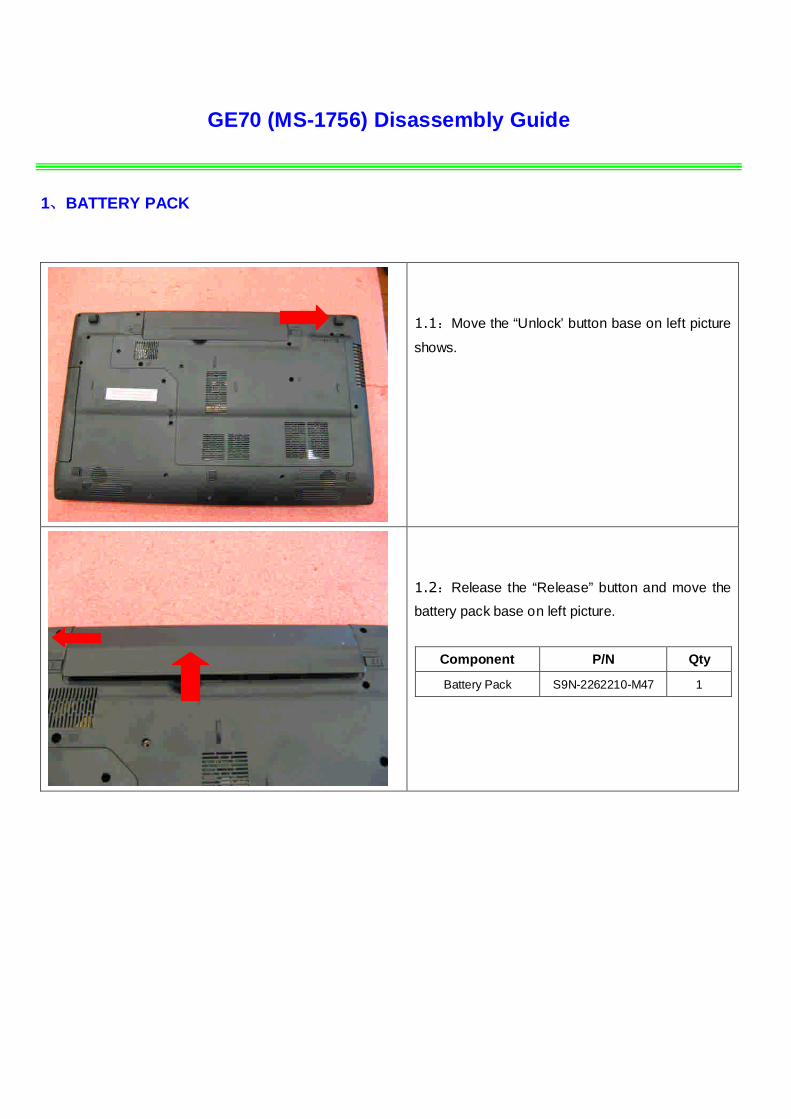
1、BATTERY PACK
1.1:Move the “Unlock’ button base on left picture
shows.
1.2:Release the “Release” button and move the
battery pack base on left picture.
Component P/N Qty
Battery Pack S9N-2262210-M47 1

GE70 (MS-1756) Disassembly Guide
2、BOTTOM DOOR ASSY
2.1 : Remove the 6 screws (M2.5*5.5mm). Then
remove the Bottom door.
Attention: the screw driver touque is: 2.0-2.5 gf-cm
Component P/N Qty
Bottom door E2P-751J211-P89 1
Screw E43-1255501-H29 6
GE70 (MS-1756) Disassembly Guide
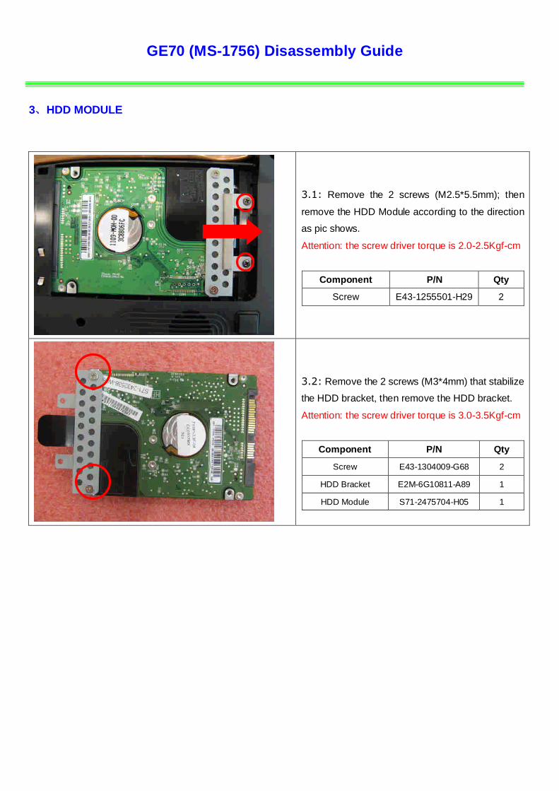
3、HDD MODULE
3.1: Remove the 2 screws (M2.5*5.5mm); then
remove the HDD Module according to the direction
as pic shows.
Attention: the screw driver torque is 2.0-2.5Kgf-cm
Component P/N Qty
Screw E43-1255501-H29 2
3.2: Remove the 2 screws (M3*4mm) that stabilize
the HDD bracket, then remove the HDD bracket.
Attention: the screw driver torque is 3.0-3.5Kgf-cm
Component P/N Qty
Screw E43-1304009-G68 2
HDD Bracket E2M-6G10811-A89 1
HDD Module S71-2475704-H05 1
GE70 (MS-1756) Disassembly Guide
4、THERMAL-KIT、CPU 、DRAM AND WIRELESS
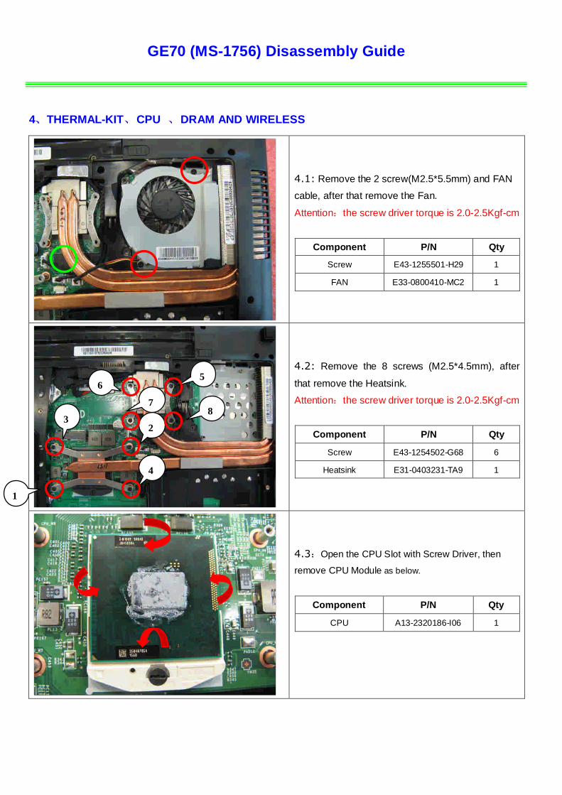
4.1: Remove the 2 screw(M2.5*5.5mm) and FAN
cable, after that remove the Fan.
Attention:the screw driver torque is 2.0-2.5Kgf-cm
Component P/N Qty
Screw E43-1255501-H29 1
FAN E33-0800410-MC2 1
4.2: Remove the 8 screws (M2.5*4.5mm), after
that remove the Heatsink.
Attention:the screw driver torque is 2.0-2.5Kgf-cm
Component P/N Qty
Screw E43-1254502-G68 6
Heatsink E31-0403231-TA9 1
4.3:Open the CPU Slot with Screw Driver, then
remove CPU Module as below.
Component P/N Qty
CPU A13-2320186-I06 1
1
2
4
3
65
87
GE70 (MS-1756) Disassembly Guide
4、THERMAL-KIT、CPU 、DRAM AND WIRELESS
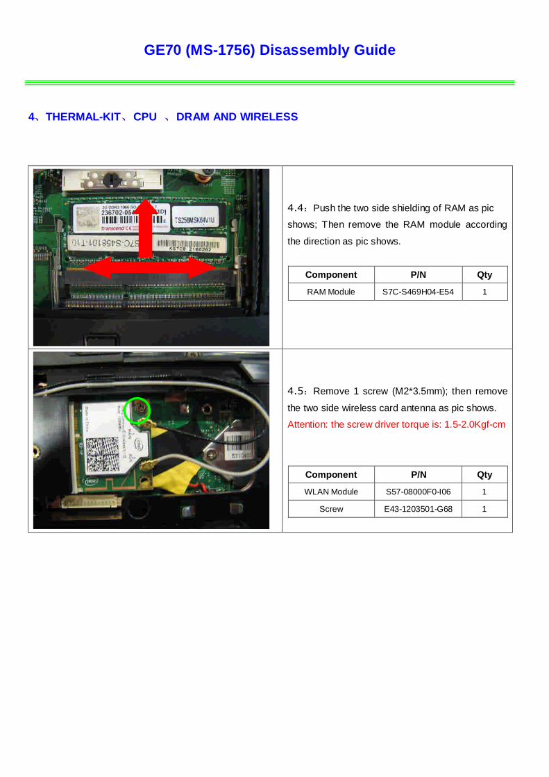
4.4:Push the two side shielding of RAM as pic
shows; Then remove the RAM module according
the direction as pic shows.
Component P/N Qty
RAM Module S7C-S469H04-E54 1
4.5:Remove 1 screw (M2*3.5mm); then remove
the two side wireless card antenna as pic shows.
Attention: the screw driver torque is: 1.5-2.0Kgf-cm
Component P/N Qty
WLAN Module S57-08000F0-I06 1
Screw E43-1203501-G68 1

GE70 (MS-1756) Disassembly Guide
5、ODD MODULE
5.1:Remove the ODD Module according to the
direction as pic shows.
5.2:Remove ODD Bezel as below.
Component P/N Qty
ODD Bezel 307-751F212-P89 1
5.3:Remove 2pcs (M2*3mm) Screws; Then remove
ODD Bracket as below.
Attention:the screw driver torque is 1.5-2.0Kgf-cm
Component P/N Qty
Screw E43-1203013-G68 2
ODD Bracket E2M-6G10711-A89 1
ODD Module S7D-2270076-T87 1

GE70 (MS-1756) Disassembly Guide
6、SEPARATE UPPER CASE AND LOWER CASE
6.1:Remove the Keyboard. Firstly release the
hook of the upside, then remove the upside, after
that release the hook of the two sides, then remove
the two sides, last remove down side.
,
6.2 : Firstly push connector according to the
direction as pic shows; then remove the cable.
Component P/N Qty
Keyboard S1N-3EUS231-SA0 1
6.3:Firstly open the connector according to the
direction as pic shows; then remove the Power
board and Touchpad cable.
Power board
Touchpad
Touchpad Button
GE70 (MS-1756) Disassembly Guide
6、SEPARATE UPPER CASE AND LOWER CASE
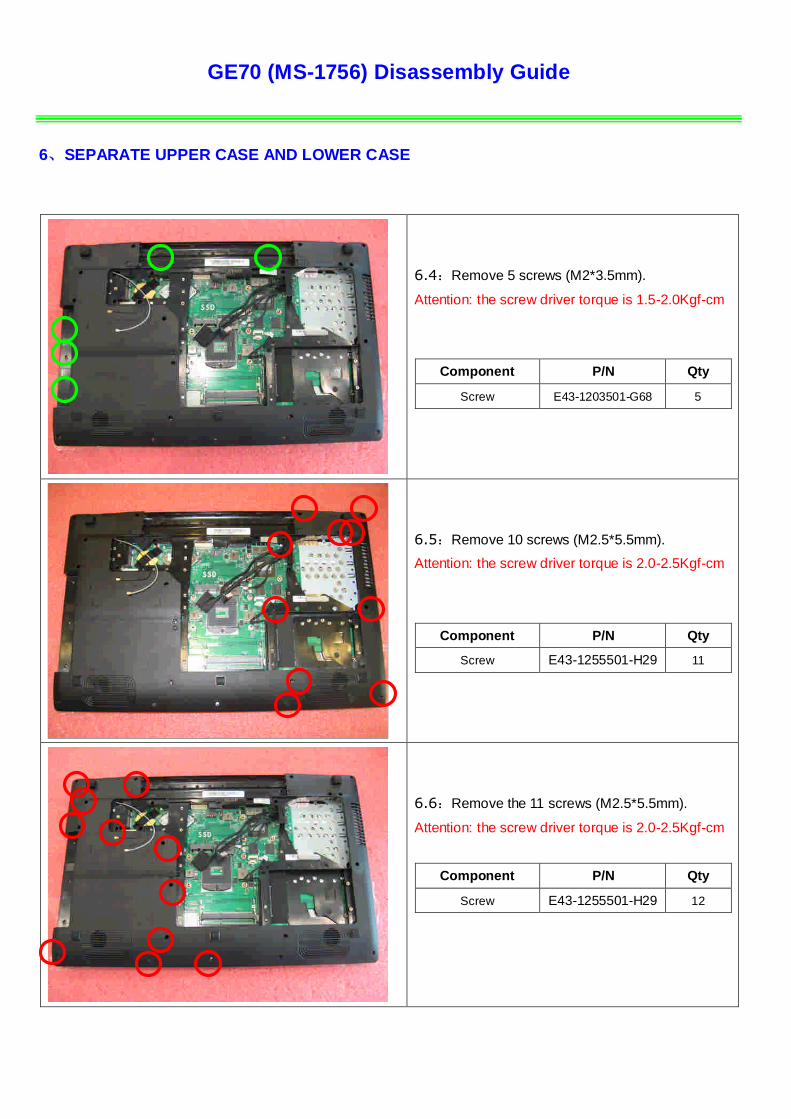
6.4:Remove 5 screws (M2*3.5mm).
Attention: the screw driver torque is 1.5-2.0Kgf-cm
Component P/N Qty
Screw E43-1203501-G68 5
6.5:Remove 10 screws (M2.5*5.5mm).
Attention: the screw driver torque is 2.0-2.5Kgf-cm
Component P/N Qty
Screw E43-1255501-H29 11
6.6:Remove the 11 screws (M2.5*5.5mm).
Attention: the screw driver torque is 2.0-2.5Kgf-cm
Component P/N Qty
Screw E43-1255501-H29 12
GE70 (MS-1756) Disassembly Guide
6、SEPARATE UPPER CASE AND LOWER CASE
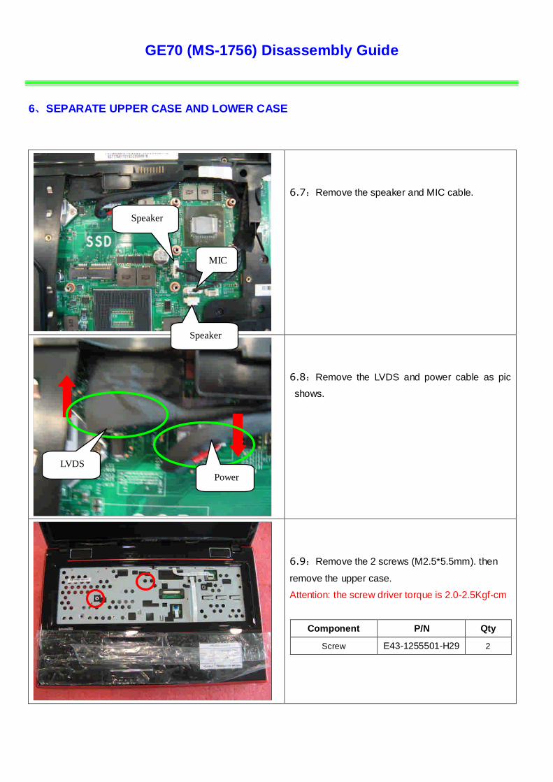
6.7:Remove the speaker and MIC cable.
6.8:Remove the LVDS and power cable as pic
shows.
6.9:Remove the 2 screws (M2.5*5.5mm). then
remove the upper case.
Attention: the screw driver torque is 2.0-2.5Kgf-cm
Component P/N Qty
Screw E43-1255501-H29 2
MIC
Speaker
Speaker
Power
LVDS
GE70 (MS-1756) Disassembly Guide
7、LOWER CASE ASSY
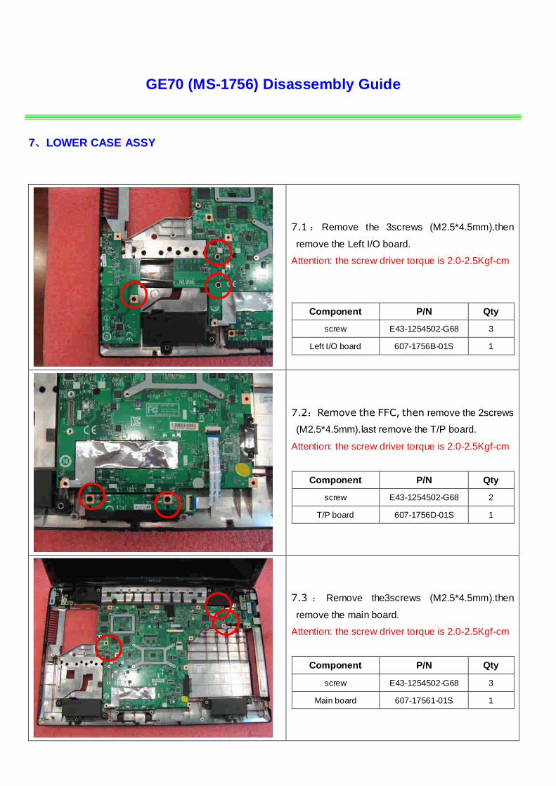
7.1 : Remove the 3screws (M2.5*4.5mm).then
remove the Left I/O board.
Attention: the screw driver torque is 2.0-2.5Kgf-cm
Component P/N Qty
screw E43-1254502-G68 3
Left I/O board 607-1756B-01S 1
7.2:Remove the FFC, then remove the 2screws
(M2.5*4.5mm).last remove the T/P board.
Attention: the screw driver torque is 2.0-2.5Kgf-cm
Component P/N Qty
screw E43-1254502-G68 2
T/P board 607-1756D-01S 1
7.3 : Remove the3screws (M2.5*4.5mm).then
remove the main board.
Attention: the screw driver torque is 2.0-2.5Kgf-cm
Component P/N Qty
screw E43-1254502-G68 3
Main board 607-17561-01S 1
GE70 (MS-1756) Disassembly Guide
7、LOWER CASE ASSY
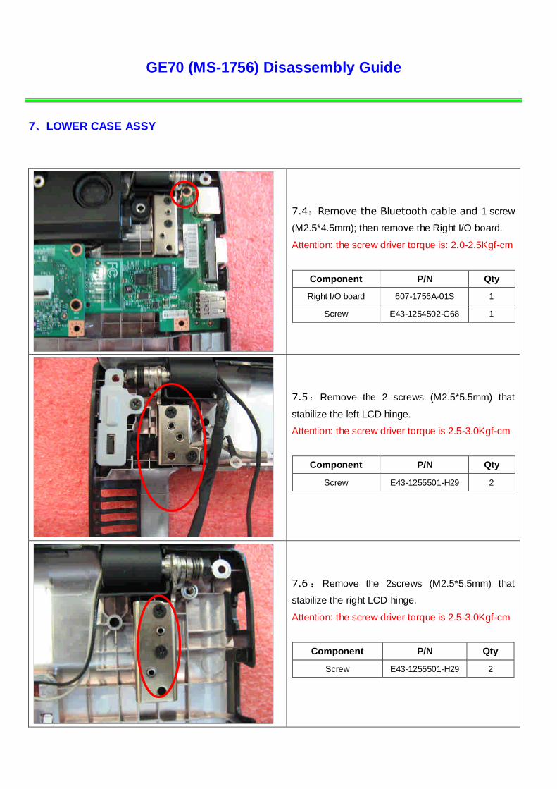
7.4:Remove the Bluetooth cable and 1 screw
(M2.5*4.5mm); then remove the Right I/O board.
Attention: the screw driver torque is: 2.0-2.5Kgf-cm
Component P/N Qty
Right I/O board 607-1756A-01S 1
Screw E43-1254502-G68 1
7.5:Remove the 2 screws (M2.5*5.5mm) that
stabilize the left LCD hinge.
Attention: the screw driver torque is 2.5-3.0Kgf-cm
Component P/N Qty
Screw E43-1255501-H29 2
7.6 : Remove the 2screws (M2.5*5.5mm) that
stabilize the right LCD hinge.
Attention: the screw driver torque is 2.5-3.0Kgf-cm
Component P/N Qty
Screw E43-1255501-H29 2
GE70 (MS-1756) Disassembly Guide
7、LOWER CASE ASSY
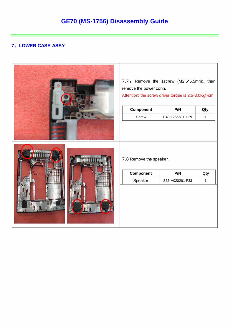
7.7 : Remove the 1screw (M2.5*5.5mm), then
remove the power conn.
Attention: the screw driver torque is 2.5-3.0Kgf-cm
Component P/N Qty
Screw E43-1255501-H29 1
7.8 Remove the speaker.
Component P/N Qty
Speaker S33-A020261-F33 1

GE70 (MS-1756) Disassembly Guide
8、UPPER CASE ASSY
8.1:Remove 2 screws (M2*3.5mm), then remove
the Power board.
Attention: the screw driver torque is 1.5-2.0Kgf-cm
Component P/N Qty
screw E43-1203501-G68 2
Power board 607-1756C-01S 1
8.2:Remove 1 screw (M2*3.5mm), then remove
the USB board.
Attention: the screw driver torque is 1.5-2.0Kgf-cm
Component P/N Qty
screw E43-1203501-G68 1
USB board 607-1756E-01S 1
8.3:Release the connector that stabilize the T/P
Cable, then remove the T/P module.
Component P/N Qty
Upper Case 307-756C211-P89 1
Touchpad Module S78-3700610-E47 1
GE70 (MS-1756) Disassembly Guide
9、 LCD MODULE ASSY
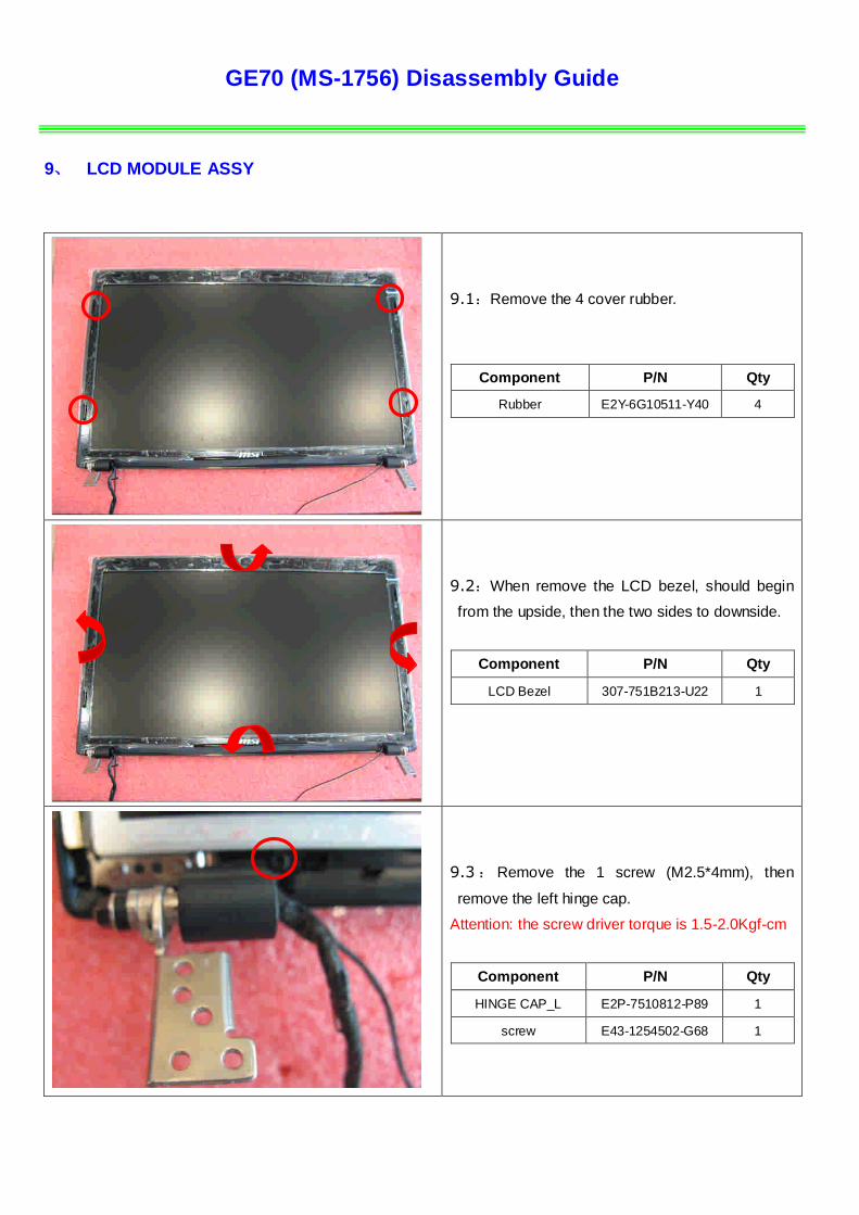
9.1:Remove the 4 cover rubber.
Component P/N Qty
Rubber E2Y-6G10511-Y40 4
9.2:When remove the LCD bezel, should begin
from the upside, then the two sides to downside.
Component P/N Qty
LCD Bezel 307-751B213-U22 1
9.3 : Remove the 1 screw (M2.5*4mm), then
remove the left hinge cap.
Attention: the screw driver torque is 1.5-2.0Kgf-cm
Component P/N Qty
HINGE CAP_L E2P-7510812-P89 1
screw E43-1254502-G68 1
GE70 (MS-1756) Disassembly Guide
9、 LCD MODULE ASSY
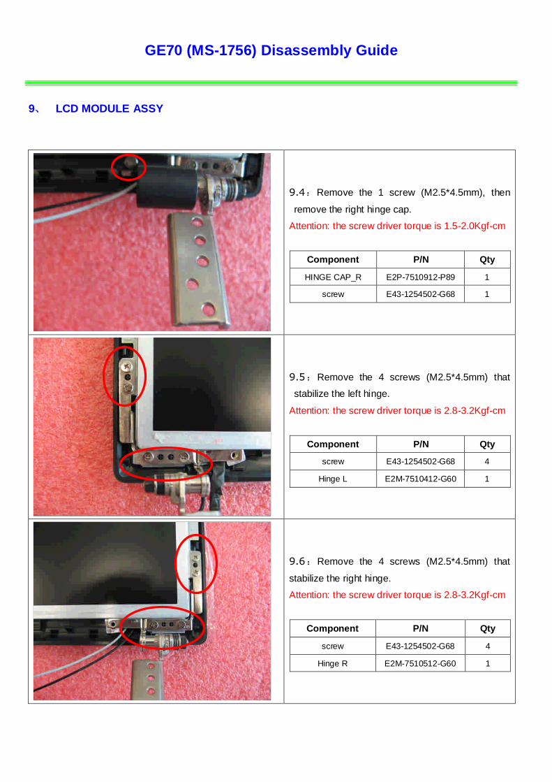
9.4:Remove the 1 screw (M2.5*4.5mm), then
remove the right hinge cap.
Attention: the screw driver torque is 1.5-2.0Kgf-cm
Component P/N Qty
HINGE CAP_R E2P-7510912-P89 1
screw E43-1254502-G68 1
9.5:Remove the 4 screws (M2.5*4.5mm) that
stabilize the left hinge.
Attention: the screw driver torque is 2.8-3.2Kgf-cm
Component P/N Qty
screw E43-1254502-G68 4
Hinge L E2M-7510412-G60 1
9.6:Remove the 4 screws (M2.5*4.5mm) that
stabilize the right hinge.
Attention: the screw driver torque is 2.8-3.2Kgf-cm
Component P/N Qty
screw E43-1254502-G68 4
Hinge R E2M-7510512-G60 1
GE70 (MS-1756) Disassembly Guide
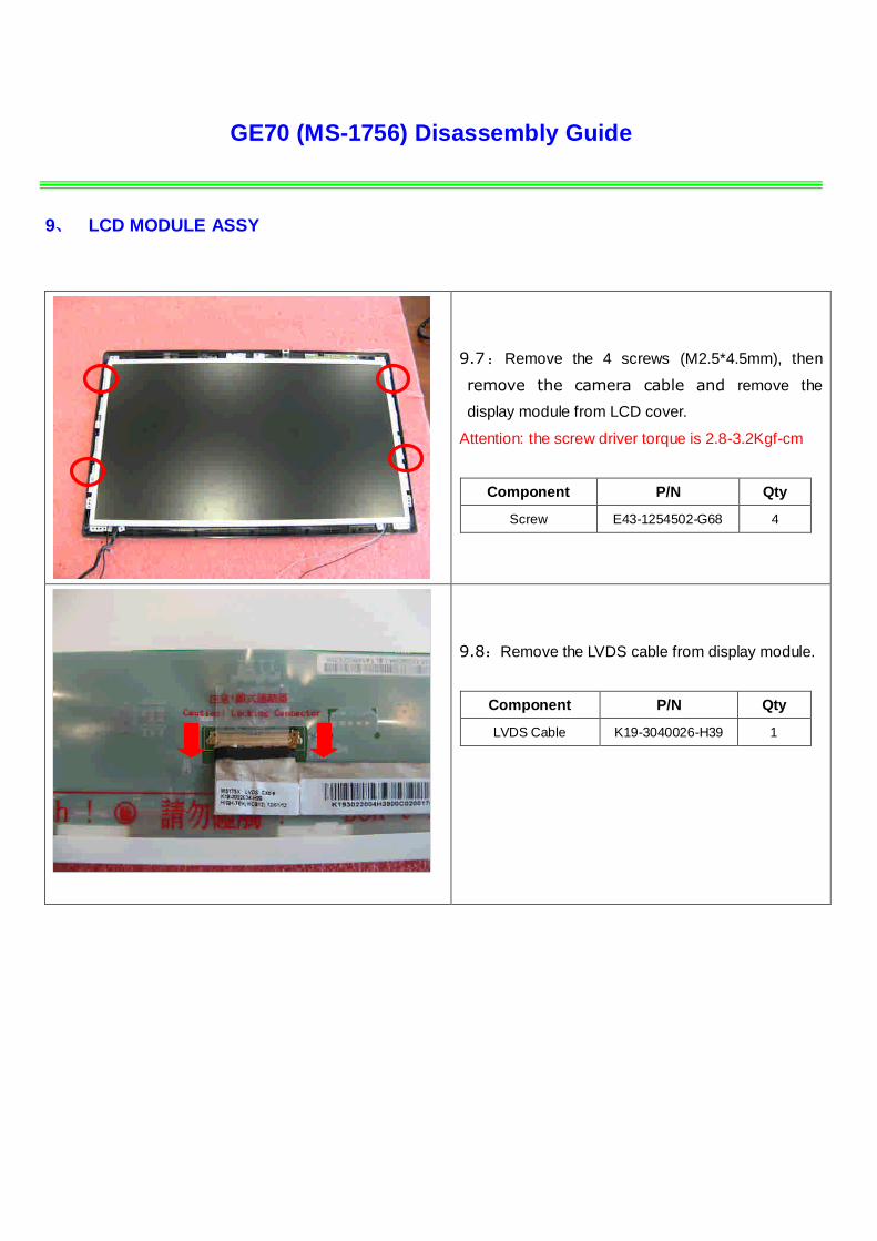
9、 LCD MODULE ASSY
9.7:Remove the 4 screws (M2.5*4.5mm), then
remove the camera cable and remove the
display module from LCD cover.
Attention: the screw driver torque is 2.8-3.2Kgf-cm
Component P/N Qty
Screw E43-1254502-G68 4
9.8:Remove the LVDS cable from display module.
Component P/N Qty
LVDS Cable K19-3040026-H39 1

GE70 (MS-1756) Disassembly Guide
9、 LCD MODULE ASSY
9.9:Remove the 8 screws (M2*3mm)
Attention: the screw driver torque is 1.5-2.0Kgf-cm
Component P/N Qty
Display Module S1J-7E0A004-CC1 1
LCD BRACKET-L E2M-7510611-C22 1
LCD BRACKET-R E2M-7510711-C22 1
Screw E43-1203013-G68 8
9.10:Remove the CMOS camera module
according to the sequence as pic shows.
Component P/N Qty
MIC Module S34-2101240-N44 1
GE70 (MS-1756) Disassembly Guide
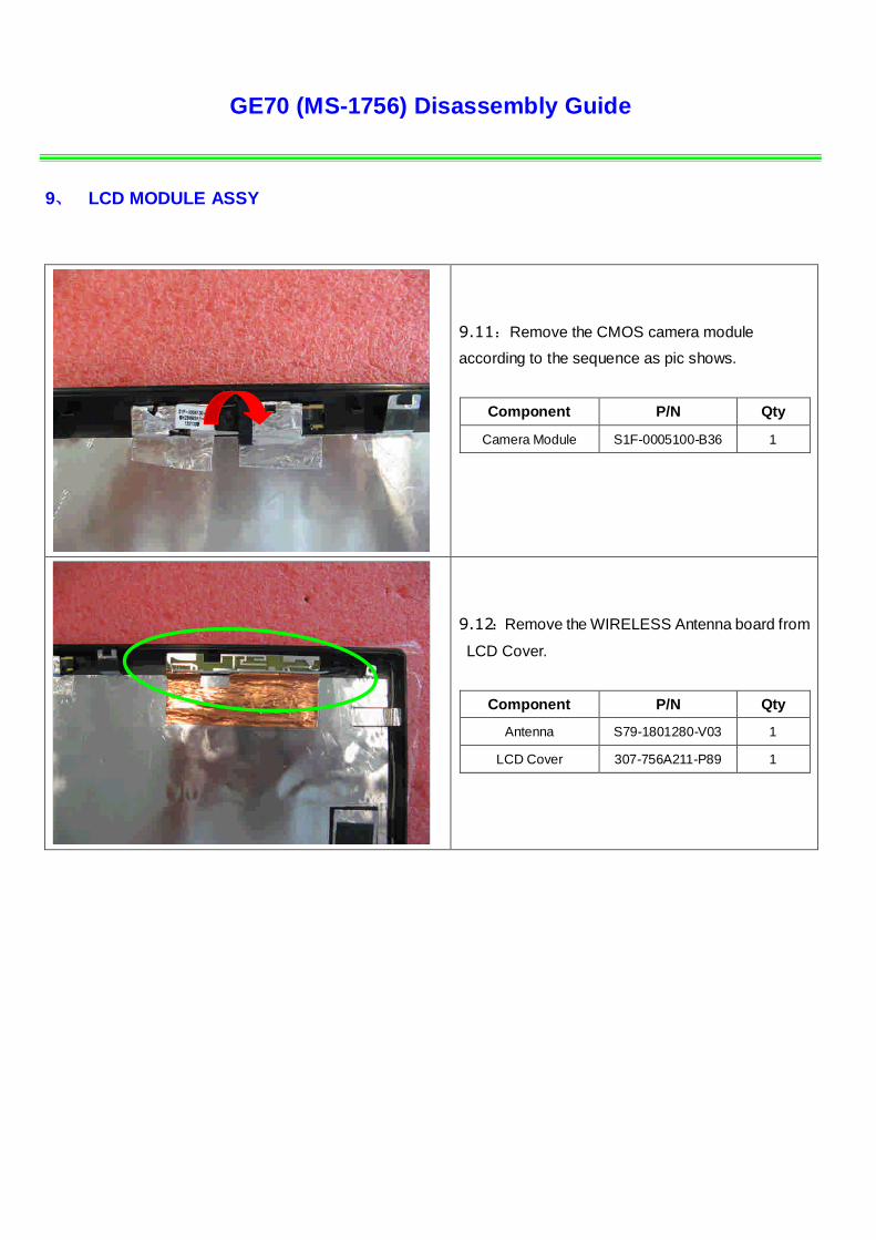
9、 LCD MODULE ASSY
9.11:Remove the CMOS camera module
according to the sequence as pic shows.
Component P/N Qty
Camera Module S1F-0005100-B36 1
9.12:Remove the WIRELESS Antenna board from
LCD Cover.
Component P/N Qty
Antenna S79-1801280-V03 1
LCD Cover 307-756A211-P89 1
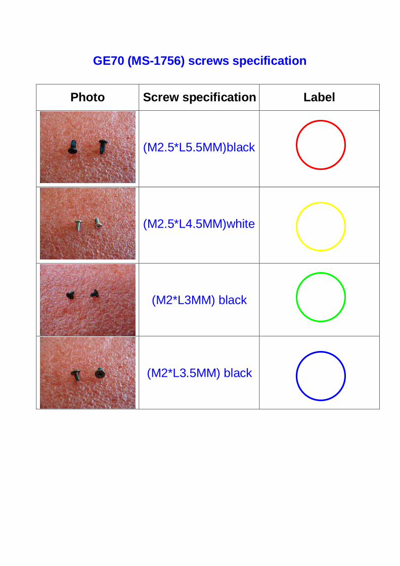
GE70 (MS-1756) screws specification
Photo Screw specification Label
(M2.5*L5.5MM)black
(M2.5*L4.5MM)white
(M2*L3MM) black
(M2*L3.5MM) black

GE70 (MS-1756)screws specification
■ 1、BOTTOM ASSY total 24 pcs screws
■ specification:
Photo Screw specification label
(M2.5*L5.5MM) black
GE70 (MS-1756)screws specification
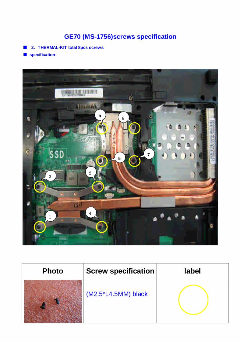
■ 2、THERMAL-KIT total 8pcs screws
■ specification:
Photo Screw specification label
(M2.5*L4.5MM) black
1
2
6
3
4
5
8
7
GE70 (MS-1756)screws specification
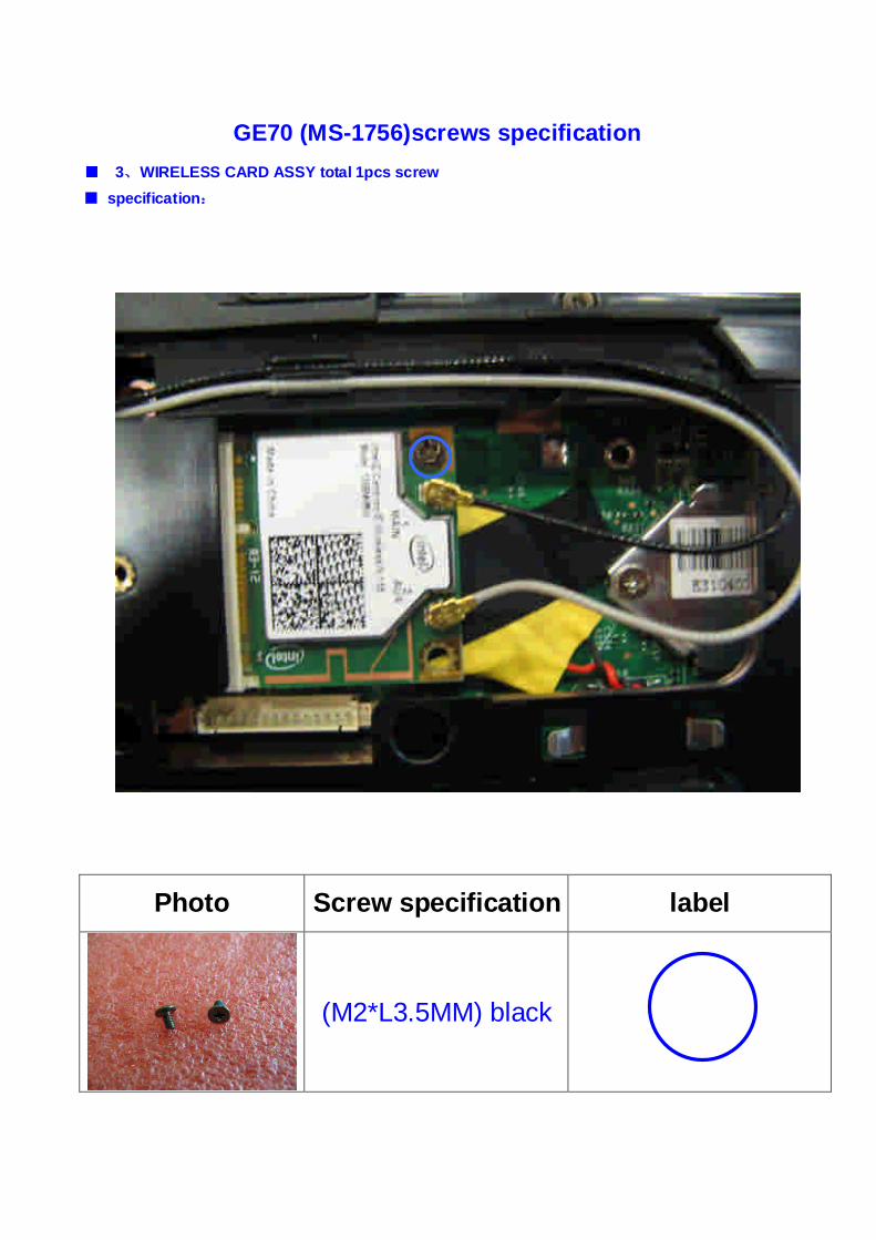
■ 3、WIRELESS CARD ASSY total 1pcs screw
■ specification:
Photo Screw specification label
(M2*L3.5MM) black
GE70 (MS-1756)screws specification
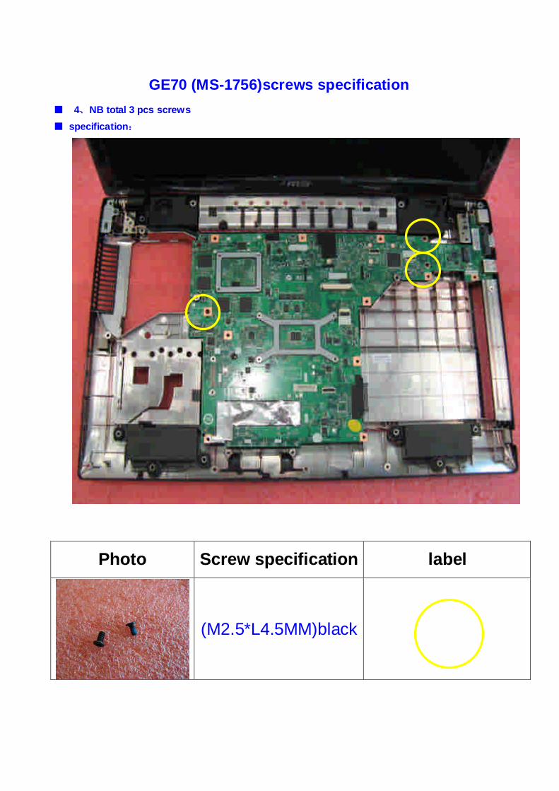
■ 4、NB total 3 pcs screws
■ specification:
Photo Screw specification label
(M2.5*L4.5MM)black

GE70 (MS-1756)screws specification
■ 5、LCD HINGE ASSY total 4pcs screws
■ specification:
Photo Screw specification Label
(M2.5*L5.5MM)black
GE70 (MS-1756)screws specification
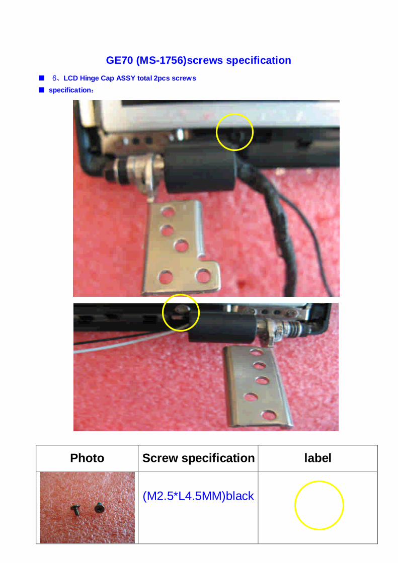
■ 6、LCD Hinge Cap ASSY total 2pcs screws
■ specification:
Photo Screw specification label
(M2.5*L4.5MM)black
GE70 (MS-1756)screws specification
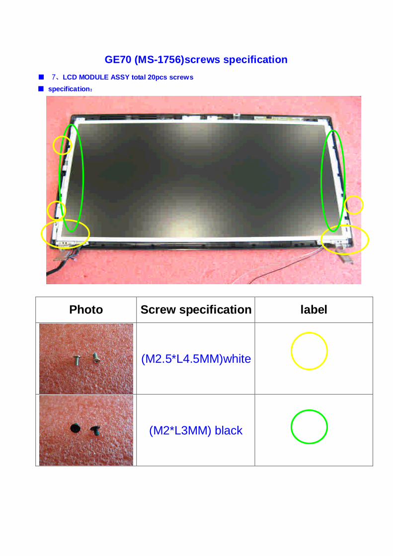
■ 7、LCD MODULE ASSY total 20pcs screws
■ specification:
Photo Screw specification label
(M2.5*L4.5MM)white
(M2*L3MM) black