ms2.2.1.4 finale senza bibio - · eu contract number rii3-ct-2003-506395 care note-05-003-srf srf...
TRANSCRIPT

EU contract number RII3-CT-2003-506395 CARE Note-05-003-SRF
SRF
“Improved Standard Cavity Fabrication”
Paolo Michelato, Laura Monaco, Roberto Paulon, INFN Sezione di Milano, Lab. LASA
Work supported by the European Community-Research Infrastructure Activity under the FP6 “Structuring the European Research Area” programme (CARE, contract number RII3-CT-2003-506395).

2/1/2005 Rev. 0 1
CARE JRA1 WP2 “Improved Standard Cavity Fabrication”
Task 2.2: Improved component design
Milestone 2.2.1.3: summary report on the status of art on ancillaries on the
experience of various laboratories involved in SC RF.
Summary
This document describes and reports the information retrieving activity performed, in the CARE
SRF context, for the Superconductive Cavities ancillaries.
The retrieving and the analysis of the experience of different laboratories working in the field of SC
cavities is the first step foreseen for the modification both of the cavity design and the preparation
procedure, to improve the performance and the reliability of the SRF accelerating system.
This document is mainly based on the experience of DESY (TTF 1, TTF 2), SNS, RIA and the
European ADS activity.
We collected information as technical drawings, data, pictures, assembling procedures, materials,
etc. relative to the following items: cold flanges, He tank, and cavity stiffening.
In particular, for what concerns the flanges and the sealing that have to operate at cryogenic
temperatures, we have collected the main parameters as the flange and sealing materials, the
dimensions, the closing torque, together with some technical drawings. Besides of that, we collected
also the data relative to commercial cold connections as Helicoflex.
The information has been referenced and a list of the papers and the sources of the information are
reported at the end of the document.
2/1/2005 Rev. 0 2
Document contributors:
INFN Sezione di Milano, Lab. LASA: Paolo Michelato, Laura Monaco, Roberto Paulon.
2/1/2005 Rev. 0 3
Summary report on the status of art on ancillaries on the
experience of various laboratories involved in SC RF.
Index
1. Introduction 4
2. Stiffening 9
2.1. Tesla TTF 10
2.2. SNS 18
2.3. RIA 22
2.4. ADS European program 24
2.4.1. TRASCO 24
2.4.2. XADS 27
3. He vessel 29
3.1. TESLA/TTF 29
3.2. CEBAF 34
3.3. SNS 35
3.4. RIA 37
3.5. ADS European program 38
3.5.1. TRASCO 38
3.5.2. XADS 39
4. Cold Flanges and sealing 41
4.1. TESLA/TTF 41
4.2. SNS 62
4.3. ADS European program: TRASCO 77
4.4. Commercial flanges 84
5. References 87

2/1/2005 Rev. 0 4
1 IntroductionAncillaries information retrieving: laboratories and projects.
For SC cavities ancillaries information retrieving we analyzed different projects and laboratories:
DESY (TTF 1, TTF 2, TESLA, XFEL), CEBAF, SNS, RIA, XADS / TRASCO, JAERI, KEK-B,
etc. We concentrated our effort retrieving data relative to cavity stiffening, helium vessels and cold
flanges. The final aim is to make available information that will be used in the next future for the
improvement of the SC cavities performances and reliability, foreseen in the CARE SRF program.
Our work has been organized retrieving information from published papers, drawings, talks,
presentations, from the web and private communication.
First is presented a concise summary of the main characteristics of the existing projects in the
different laboratories: the rules employed in this first selection are mainly the use of massive Nb
cavities, the number of cavities produced/used for the machine, the availability of information, etc.
The large part of the document is based on the information available from DESY (TTF 1, TTF2,
TESLA, XFEL), CEBAF, SNS, RIA and the European ADS activity.

01/02/2005 Rev 0 5
lab. beam structure Cavities and cryomodules Images Status
TESLA (TeV Energy Superconducting Linear Accelerator)
DESY, TESLA-collaboration
Pulsed (RF pulse=1.3ms)
Electron positron linear collider
9-cell, 1.3 GHz, Eacc = 35MV/m, =1; 8-cavities per cryomodule
Only project
TTF I (Tesla Test Facility)
DESY, TESLA-collaboration
Pulsed (RF pulse=1.3ms)
Electron linac, equipped with SASE FEL (saturation @ 80nm)
9-cell, 1.3 GHz, Eacc >15MV/m, =1; 8-cavities per cryomodule
In operationfrom 1998to 2003. Dismissed in 2003
TTF II (Tesla Test Facility)
DESY, TESLA-collaboration
Pulsed (RF pulse=1.3ms)
Electron linac, equipped with VUV SASE FEL
9-cell, 1.3 GHz, Eacc >25MV/m, =1; 8-cavities per cryomodule
Start operation in2004
5-cell, 1.5 GHz, Eacc = 5MV/m, Q0=2.4x10⁹; 8 cavities per cryomodule
CEBAF(ContinuousElectron Beam Accelerator Facility)
TJNAF CW Recirculated linac. Designed for 4 GeV (CEBAF I), achieved 6.5 GeV. New goal to 12 GeV in ’06 (CEBAF II), 24 GeV in ‘10, Eacc=12MV/m.
7-cell, 1.5 GHz, Eacc=12.5MV/m, Q0=6.5x10⁹; 8 cavities per cryomodule
First layoutfinished in 1993. Upgraded from 1994 to 2006. In operation

01/02/2005 Rev 0 6
project laboratories
beam structure Cavities and cryomodules Images Status
6-cell, 805 MHz,=0.61, Eacc=10.2MV/m, Q=5x10⁹; 3 cavities per cryomodule
SNS(Spallation Neutron Source)
ANL, BNL, LANL, LBNL, ORNL
Pulsed Accelerator-based neutron source composed by a front-end-system, linac (from 185MeV to 840-1300 MeV), accumulator ring, target
6-cell, 805 MHz, =0.81, Eacc=12.3MV/m, Q=5x10⁹; 4 cavities per cryomodule
Under construction (start in 1999, will be finished in 2006)
6-cell, 805 MHz, =0.47, Eacc=8MV/m
6-cell, 805 MHz,=0.61, Eacc=10.2MV/m, Q=5x10⁹;
RIA (Rare IsotopeAccelerator)
NSCL, MSU, TJNAF
CW Heavy ions driver linac accelerator (to 400 MeV, 400 kW)
6-cell, 805 MHz, =0.81, Eacc=12.3MV/m, Q=5x10⁹;
Project started in 2000

01/02/2005 Rev 0 7
project laboratories beam structure Cavities and cryomodules
Images Status
INFN TRASCO(TRAsmutazione di SCOrie)
5-cell, 704.4 MHz, =0.47, Eacc=8.5MV/m [1], [2], Q0>1010[3], Q0=5x10⁹[1]
Project started in 1999. End: 2002.
ADS (Accelerator Driven System)European activity
PDS- XADS (Experimental Accelerator Driven System) 5th EUprogram
CW High intensity superconducting proton accelerator in 3 section @ 700 MHz (5-cell: =0.5, 5-cell =0.65, =0.85). Goal is 100-1600 MeV, 25mA
5-cell, 704 MHz, =0.65, Eacc =10MeV/m[4]
R&D on progressStudy started in 2001 and finished in 2004.

01/02/2005 Rev 0 8

01/02/2005 Rev 0 9
2 Cavity stiffening
Due to high field and pulsed operation, the Lorentz force produces a detuning of the cavity with respect to
the RF supply system. This fact, together with the extremely narrow bandwidth of the SC cavities, forces to
develop more stiff accelerating structures.
Recently, stiffening rings have been added also to cavities in not pulsed accelerating structures. This choice
is mainly due to the necessity to increase the mechanical stability of the cavities (as in the case of low beta
cavities like the TRASCO , SNS and RIA) and to reduce the effect of vibrations (as microphonics).
A summary of data derived from literature and relative to cavity stiffening will be presented, after a brief
introduction of main principle of cavity behavior in pulsed RF regime.

01/02/2005 Rev 0 10
2.1 TESLA/TTF
LORETZ FORCE DETUNING AND CAVITY STIFFENING
Design and principal parameters of the 1.3 GHz TTF 9-cell cavity (RF pulses of 1.3 ms) (designed for
TESLA-500) [5],[6] are in Table 2.1
Coupling cell to cell 1.98 %Nominal gradient Eacc (TESLA-500) 23.4 MV/mQuality factor >1010
Active length 1038 mmCell-to-cell coupling Kcc 1.87 %Iris diameter 70 mmR/Q 1036 Epeak/Eacc 2.0Bpeak/Eacc 4.26 mT / (MV/m)Tuning range +/- 300 kHzf/L 315 kHz / mmLorentz force detuning constant KL 1 Hz / (MV/m)2
Qext 2.5x10⁶
Cavity bandwidth (Qext=3x10⁶) [5] 433 HzCavity bandwidth (Qext=2.5x10⁶) [6] 520 Hz
Tab. 2.1: Design and principal parameters of the 1.3 GHz TTF 9 Cell cavity
The mechanical stability is a fundamental problem for RF SC cavities.
The behavior of the cavity depends also on other ancillaries mechanically connected to the cavity, as the
helium tank, the tuning system, etc.
The choice of the strategy for the cavity stiffening should be a compromise, for instance, between the cavity
mechanical stability (more thick and stable cavities), and the heat exchange capability (more thin cavities,
cheaper solution) [7].
At high accelerating gradient the cavity could be driven out of resonance by the submicron mechanical
deformations under Lorentz force detuning [7]: the steady state Lorentz force detuning at constant
accelerating gradient Eacc is:
f = KLEacc2
This quadratic dependence is also reflected in the dynamic Lorentz force detuning during the RF pulse.
The pulsed operation leads to a time-dependent frequency shift of the 9-cell cavities. The stiffening rings
joining neighboring cells are adequate to keep this Lorentz-force detuning within tolerable limits only up to
the nominal TESLA-500 gradient of 23.4 MV/m., considering a cavity bandwidth of 434 Hz [7] for the
TESLA 9-cell specification the of cavity (@ Qext = 3x10⁶).

01/02/2005 Rev 0 11
For detailed information about relationship between cavity deformations, the effect of the Lorentz force
detuning etc, see for instance reference [7] and [5].
Fig. 2.1: Measurement and calculation of the KL [7]
Actual stiffening geometry and cavity parameters are reported in the following table 2.2:
9-cell, 1.3 GHz
Lorentz Force Detuning without stiffening (cavity thickness of 2.5mm)
900 Hz @ 25MV/m [8]
Lorentz Force Detuning with stiffening (cavity thickness of 2.5mm)
About 500 Hz @ 25MV/m for 1.3ms long RF pulse [8]
Tuning range +/- 300 kHz [8]
f/L 315 kHz /mm [8]
Cav. Bandwidth equip. with RF coupler 430Hz (Qext=3x10⁶) [8], 520Hz (Qext=2.5x10⁶) [6]
Stiffening material Nb [8]
Stiff. Geometry Nb ring, welded in between adjacent cells [8]. 2mm thickness [See fig. 2.4 and 2.5]
Stiff. Position 56.5mm from the cavity axis
Tab. 2.2: Actual stiffening geometry and cavity parameters for 9 cells 1.3 GHz

01/02/2005 Rev 0 12
Fig. 2.2: Sketch of the TTF cavity: stiffening ring, reference flange and conical head plate are shown.
Fig. 2.3: 9 cell TTF cavity with stiffening ring and ancillaries [8]

01/02/2005 Rev 0 13
Fig. 2.4: TTF Dumb bell with stiffening ring.

01/02/2005 Rev 0 14
Fig. 2.5: Stiffening ring for TTF cavities

01/02/2005 Rev 0 15
For TESLA-800, the request is to have higher field: Eacc = 35 MV/m [6]: in this case, improvement on the
stiffening solution is needed or the cavity deformation must be compensated for instance using a
piezoelectric tuner. [6].
Two different strategies have been proposed: the first is based on an improvement of the cavity mechanical
properties, the second one foreseen an active deformation compensation using for instance piezo actuators.
(1) Improvement of mechanical properties
(a) plasma spray
(b) plasma spray + stiffening rings
(1a) Stiffening by plasma spray
Experimental and computational data shows that the EB welded stiffening rings alone allow a frequency
shift of the TESLA 9-cell SRF cavities higher than the cavity bandwidth above Eacc = 28 MV/m [9].
Reference [9] is relative to a proposal of a new stiffening method using a Plasma Sprayed Copper Layer
(PSCL) onto bulk Nb cavities. Test of a 1.3 GHz single-cell using the APS (Atmospheric Plasma Spray)
technique. Cavity thickness = 2.5 mm of NB (RRR=200), stiffened by 2.5 mm thick copper layer
(intermediate 0.2mm thick bonding layer of bronze/aluminum alloy, between Nb and Cu) [9].
In 2001 other tests were performed on a 1.3 GHz TESLA single-cell [10], using a new technique, IPS
(Inert gas Plasma Spraying). The following table shows the results.
Tab. 2.3: TTF Cavity performances after the copper deposition: with 2.8 mm thickness of Cu (IPS) KL goes
from -7.4 to -2.52 Hz / (MV/m)2 [7].
Coating 3.5 mm Cu layerCoating porosity and oxidation 8% and very low oxidation
Elastic propertiesYoung modulus 72 GPaUTS 124 MPaPorosity 8%Maximum elongation 0.2%Bond strength 51 MPa
Thermal propertiesThermal resistance 2 times higher respect to Nb alone
Cavity performancesBefore IPS (Nb alone) 30 MV/mAfter IPS (Cu on Nb) 18 MV/mAfter IPS (Cu on Nb) and BCP 25 MV/mKL (before IPS) -7.4 Hz / (MV/m)2
KL (after IPS) -2.5 Hz / (MV/m)2

01/02/2005 Rev 0 16
Figure 2.6 and 2.7 show the cavity before and after Cu deposition [10].
Fig. 2.6 and 2.7: Nb cavity Cu sprayed.
Calculation relative to the extrapolation for a 9 cell structure indicated that the Cu layer at the iris should be
of the order of tens of mm [10]
Implications:
Technical difficulties in the deposition process
Higher force for cavity tuning
(1b) Mixed solution: using both the stiffening rings and the Cu coating [7]
Fig. 2.8: Three different stiffenings: a) homogeneous Cu layer 2mm thick, b) Nb stiffening rings and Cu 2
mm, c) Cu layer 1.6mm and iris reinforcement 23mm.[10]
01/02/2005 Rev 0 17
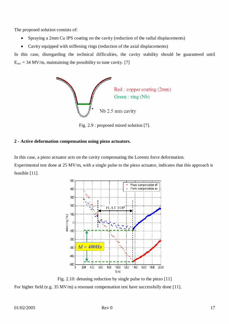
The proposed solution consists of:
Spraying a 2mm Cu IPS coating on the cavity (reduction of the radial displacements)
Cavity equipped with stiffening rings (reduction of the axial displacements)
In this case, disregarding the technical difficulties, the cavity stability should be guaranteed until
Eacc = 34 MV/m, maintaining the possibility to tune cavity. [7]
Fig. 2.9 : proposed mixed solution [7].
2 - Active deformation compensation using piezo actuators.
In this case, a piezo actuator acts on the cavity compensating the Lorentz force deformation.
Experimental test done at 25 MV/m, with a single pulse to the piezo actuator, indicates that this approach is
feasible [11].
Fig. 2.10: detuning reduction by single pulse to the piezo [11]
For higher field (e.g. 35 MV/m) a resonant compensation test have successfully done [11].
01/02/2005 Rev 0 18
2.2 SNS
LORETZ FORCE DETUNING AND CAVITY STIFFENING
SNS uses two different cavities, both at 805 MHz: 0.61 and0.81.
Both cavities have been designed to ensure the following main parameters [12], [13]:
Esurf peak ≤ 27.5 MV/m @ Eacc = 10.2 MV/m
Bsurf peak < 60 mT @ Eacc = 10.2 MV/m
KL <-3 Hz/(MV/m)2
= 0.61, 805 MHz = 0.81, 805 MHzNumber of cells 6 6Material Nb NbThickness 3.8 mm 3.8 mm
Tab. 2.4: SNS main cavity parameters [12]
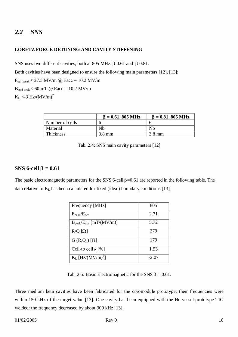
SNS 6-cell = 0.61
The basic electromagnetic parameters for the SNS 6-cell =0.61 are reported in the following table. The
data relative to KL has been calculated for fixed (ideal) boundary conditions [13]
Frequency [MHz] 805
Epeak/Eacc 2.71
Bpeak/Eacc [mT/(MV/m)] 5.72
R/Q [] 279
G (RsQ0) [] 179
Cell-to cell k [%] 1.53
KL [Hz/(MV/m)2] -2.07
Tab. 2.5: Basic Electromagnetic for the SNS = 0.61.
Three medium beta cavities have been fabricated for the cryomodule prototype: their frequencies were
within 150 kHz of the target value [13]. One cavity has been equipped with the He vessel prototype TIG
welded: the frequency decreased by about 300 kHz [13].

01/02/2005 Rev 0 19
The He vessel for cavity production will be stiffened by welding titanium cones on the two heads to lower
the Lorentz force coefficient. [13]
Calculation for the assembly“cavity-He vessel-tuner” resulted in a static Lorentz force coefficient of about
3.64 Hz/(MV/m)2 [13]. Therefore, further stiffening of the He vessel is necessary to achieve the specified
values for the Lorentz force detuning. [14].
The next table shows a comparison between measurement and calculation results, for stiffened and
unstiffened cavities, for the KL [14]. Stiffening was at 70 mm (thickness 3 mm). In the final configuration,
the stiffening ring diameter is moved to 80 mm.
= 0.61 Calculated values Measured data
No stiffening Stiffening @ 70mm With stiffening ring
Fixed end -2.89 -1.65
Ti frame -7.85 -7.0 -8.25
He vessel -4 -3.55
Free end -31.1 -27.0
Tab. 2.6: comparison between calculated and measured data for = 0.61 [14]
In 2002 the KL coefficient of a cavity equipped with He vessel and tuner was measured. [15]
Data are in the next table.
= 0.61 Measured
With He vessel -7 Hz/(MV/m)2
With He vessel and tuner -3 Hz/(MV/m)2
Model (with He vessel and tuner) -3.6 Hz/(MV/m)2
(considering tuner stiffness = 2x10⁶ kg/m)
-2.9 Hz/(MV/m)2
(considering tuner stiffness = 3.4x10⁶ kg/m)
Tab. 2.7: KL coefficient measurement in 2002. [15]
01/02/2005 Rev 0 20
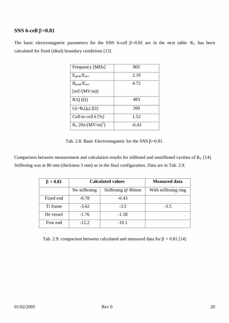
SNS 6-cell =0.81
The basic electromagnetic parameters for the SNS 6-cell =0.81 are in the next table: KL has been
calculated for fixed (ideal) boundary conditions [13]
Frequency [MHz] 805
Epeak/Eacc 2.19
Bpeak/Eacc
[mT/(MV/m)]
4.72
R/Q [] 483
G(=RsQ0) [] 260
Cell-to cell k [%] 1.52
KL [Hz/(MV/m)2] -0.43
Tab. 2.8: Basic Electromagnetic for the SNS =0.81.
Comparison between measurement and calculation results for stiffened and unstiffened cavities of KL [14].
Stiffening was at 80 mm (thickness 3 mm) as in the final configuration. Data are in Tab. 2.9.
= 0.81 Calculated values Measured data
No stiffening Stiffening @ 80mm With stiffening ring
Fixed end -0.78 -0.43
Ti frame -3.62 -3.5 -3.5
He vessel -1.76 -1.58
Free end -12.2 -10.1
Tab. 2.9: comparison between calculated and measured data for = 0.81 [14]
01/02/2005 Rev 0 21
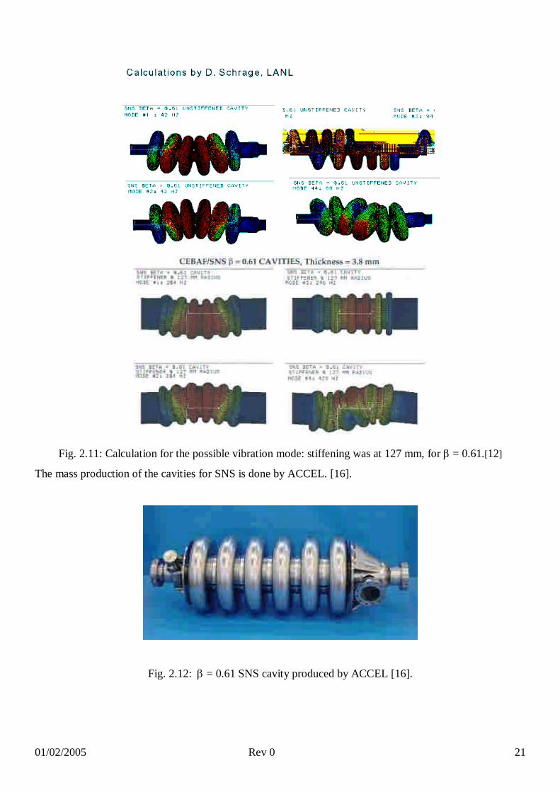
Fig. 2.11: Calculation for the possible vibration mode: stiffening was at 127 mm, for = 0.61.[12]
The mass production of the cavities for SNS is done by ACCEL. [16].
Fig. 2.12: = 0.61 SNS cavity produced by ACCEL [16].

01/02/2005 Rev 0 22
2.3 RIA
Rare Isotope Accelerator employs three kinds of elliptical cavities with 0.47, 0.61 and 0.81.
Cavities with 0.61 and 0.81 are the same as the SNS project.
The cavity 0.47 is the only one that has been developed. [17]
STIFFENING for 6-cell, =0.47 [18]
Lorentz Force Detuning with stiffening KL = -13.7 Hz/(MV/m)2, quite high but ok due to the CW
machine [19] [20]
Stiffening material Nb, Thickness= 3.8 mm
Stiff. Geometry Stiffening ring
Tab. 2.10: RIA = 0.47 stiffening parameters.
The high value of the Lorentz coefficient (KL -13.7 Hz/(MV/m)2, should not be a problem in itself, since RIA is
a CW machine but microphonics may be an issue due to the relatively low beam loading. [19].
Fig. 2.13: RIA cavities. Stiffening rings are shown. [21]

01/02/2005 Rev 0 23
Fig. 2.13. a) Drawing of the 0.47 without stiffening ring. b) Picture of the same cavity during vertical test.
c) and d) Drawing and picture of the stiffened 0.47 cavity. [18]
01/02/2005 Rev 0 24
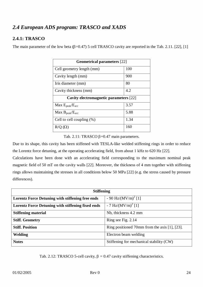
2.4 European ADS program: TRASCO and XADS
2.4.1: TRASCO
The main parameter of the low beta (=0.47) 5 cell TRASCO cavity are reported in the Tab. 2.11. [22], [1]
Tab. 2.11: TRASCO =0.47 main parameters.
Due to its shape, this cavity has been stiffened with TESLA-like welded stiffening rings in order to reduce
the Lorentz force detuning, at the operating accelerating field, from about 1 kHz to 620 Hz [22].
Calculations have been done with an accelerating field corresponding to the maximum nominal peak
magnetic field of 50 mT on the cavity walls [22]. Moreover, the thickness of 4 mm together with stiffening
rings allows maintaining the stresses in all conditions below 50 MPa [22] (e.g. the stress caused by pressure
differences).
Stiffening
Lorentz Force Detuning with stiffening free ends - 90 Hz/(MV/m)2 [1]
Lorentz Force Detuning with stiffening fixed ends - 7 Hz/(MV/m)2 [1]
Stiffening material Nb, thickness 4.2 mm
Stiff. Geometry Ring see Fig. 2.14
Stiff. Position Ring positioned 70mm from the axis [1], [23].
Welding Electron beam welding
Notes Stiffening for mechanical stability (CW)
Tab. 2.12: TRASCO 5-cell cavity, = 0.47 cavity stiffening characteristics.
Geometrical parameters [22]
Cell geometry length (mm) 100
Cavity length (mm) 900
Iris diameter (mm) 80
Cavity thickness (mm) 4.2
Cavity electromagnetic parameters [22]
Max Epeak/Eacc 3.57
Max Bpeak/Eacc 5.88
Cell to cell coupling (%) 1.34
R/Q () 160

01/02/2005 Rev 0 25
Two 5 cell cavities have been produced, namely Z 501 and Z502. Measurements done at JLAB and
SACLAY have show, on the stiffened cavity, KL value ranging between - 20 to - 47 Hz/(MV/m)2 depending
on the boundary conditions of the tests. [1].
Fig. 2.14 shows the stiffening ring, Fig. 2.15 the stiffening ring position and the bell profile.
Fig. 2.14: TRASCO stiffening ring .

01/02/2005 Rev 0 26
Fig. 2.15: The stiffening ring position and the bell profile [INFN]
01/02/2005 Rev 0 27
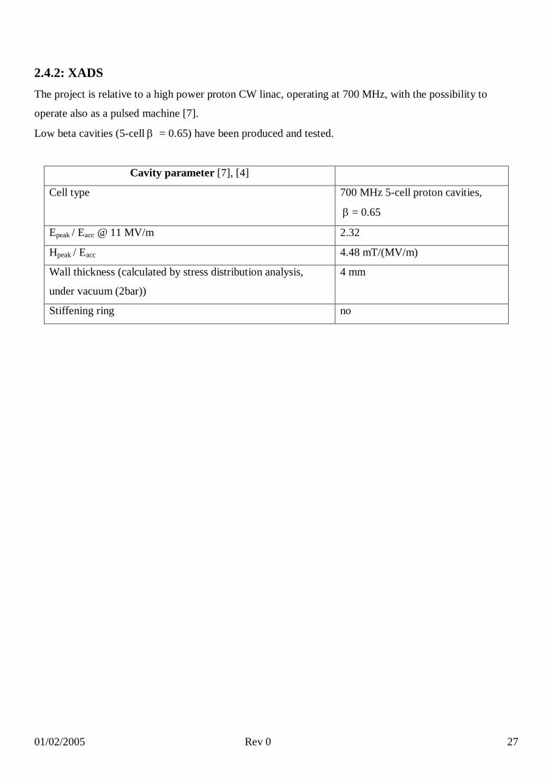
2.4.2: XADS
The project is relative to a high power proton CW linac, operating at 700 MHz, with the possibility to
operate also as a pulsed machine [7].
Low beta cavities (5-cell = 0.65) have been produced and tested.
Cavity parameter [7], [4]
Cell type 700 MHz 5-cell proton cavities,
= 0.65
Epeak / Eacc @ 11 MV/m 2.32
Hpeak / Eacc 4.48 mT/(MV/m)
Wall thickness (calculated by stress distribution analysis,
under vacuum (2bar))
4 mm
Stiffening ring no

01/02/2005 Rev 0 28
01/02/2005 Rev 0 29
3 He Vessel
Th Helium vessel contains the helium needed for cooling and serves at the same time as a mechanical
support of the cavity and as a part of the tuning mechanism. Besides that, it is usually used for the transfer
of the forces that the tuning system applies to the cavity.
3.1 TESLA/TTF
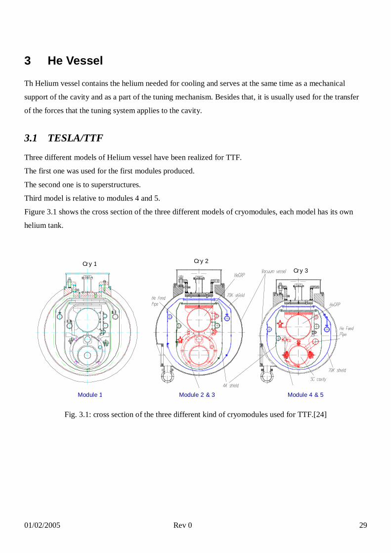
Three different models of Helium vessel have been realized for TTF.
The first one was used for the first modules produced.
The second one is to superstructures.
Third model is relative to modules 4 and 5.
Figure 3.1 shows the cross section of the three different models of cryomodules, each model has its own
helium tank.
Fig. 3.1: cross section of the three different kind of cryomodules used for TTF.[24]
Cry 1 Cry 2Cry 3
Module 1 Module 2 & 3 Module 4 & 5

01/02/2005 Rev 0 30
He VESSELMaterial He vessel
componentsWelding technique
Assembly procedure Tuning system
Ti 2 conical head plates(Nb), 1 Ti bellows, 1 Ti ring, 1 Ti vessel.
EB welded to Nb.
1 Ti bellows is EB welded to the conical Nb head plate at one side of the cavity. 1 Ti ring is EB welded to the conical Nb head plate at the other side. The cavity is then inserted into the tank. Bellows and Ti ring are TIG welded to the Ti vessel.
The Tuning system is linked to the He vessel. It consists of a stepping motor with gearbox and a double lever arm. Moving parts operate @ 2 K in vacuum.
Tab. 3.1: He vessel characteristics [8].
Fig. 3.2: First model of the helium vessel: the two phase feeding tube is on the axis of the structure. [25]

01/02/2005 Rev 0 31
Fig. 3.3: First model of the helium vessel.

01/02/2005 Rev 0 32
A second model of the helium vessel was used for superstructures. The drawing is shown in Fig. 3.4.
Fig. 3.4: Helium vessel for the superstructures.
01/02/2005 Rev 0 33
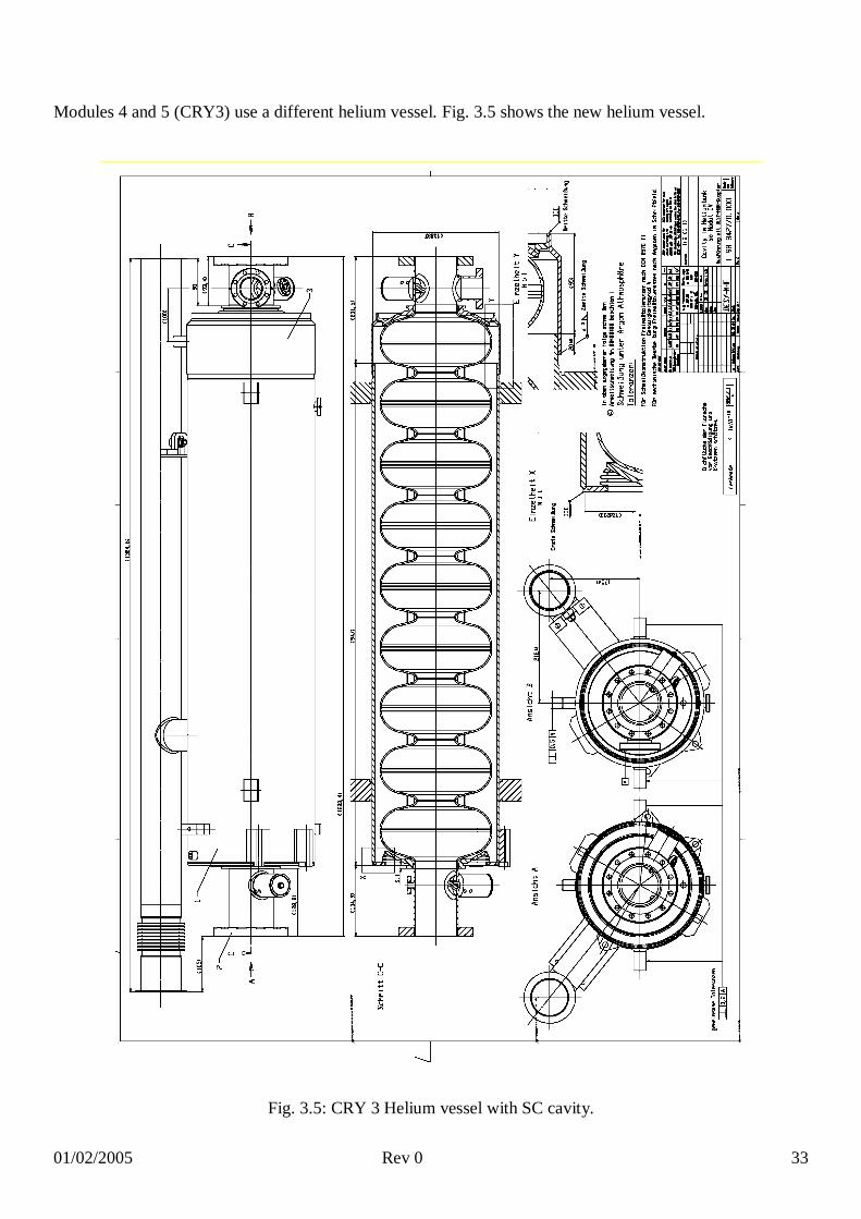
Modules 4 and 5 (CRY3) use a different helium vessel. Fig. 3.5 shows the new helium vessel.
Fig. 3.5: CRY 3 Helium vessel with SC cavity.

01/02/2005 Rev 0 34
3.2 CEBAF
He VESSEL for 7-cell cavityMaterial He vessel
componentsWelding technique
Assembly procedure Tuning system
Ti [26] 2 heads (Ti), 2 bellows (Ti), 1 cylindrical shell (Ti), 1 Nb-Ti transition ring [41]. The He vessel has been reduced from 0.61 to 0.25 meter diameter by moving the RF couplers outside of the vessel (2 Ti bellows are incorporated into the vessel) [26], [27]
The heads are welded to a niobium-titanium transition ring, which is part of the cavity end group. The bellows are located near the helium vessel head opposite the FPC and enable cavity tuning. The helium vessel heads are added to the cavity after any high temperature baking in order to avoid embitterment of the titanium. [26]
It consists of a coarse mechanical tuner and a fine piezoelectric tuner. All the components are cold, including the motor, harmonic drive and piezoelectric actuators.[26]
Tab. 3.2: CEBAF Helium vessel main characteristics
Fig. 3.6: CEBAF He –tank for 7-cell cavity [28]
Fig. 3.7: JLab “OC” shape, 1.5GHz, 7-cell niobium cavity with helium vessel removed [29]

01/02/2005 Rev 0 35
3.3 SNS
The He vessel design (developed with an ASME pressure vessel code) was dictated by [30]:
a five-atmosphere internal pressure requirement due to the potential upset condition from loss of
beamline vacuum
a two-atmosphere internal pressure requirement due to the potential upset condition from loss of
insulating vacuum
He vessel for 6-cell = 0.61
Material Ti, Nb/Ti [12]
He vessel
components
Bellow: Ti (hydro-formed [16]), Dished head: NbTi (thickness = 6.35 mm) [30],
shell: Ti (thickness = 4.76 mm)
Dimension Tubes: diameter = 24 in.=610 mm [30], thickness = = 4.76 mm [30]
Welding
technique
Ti He vessel TIG welded [13]. The He vessel for cavity production will be stiffened by
welding titanium cones on the two heads to lower the Lorentz force coefficient [13].
Assembly
and welding
procedure
The welding of the helium vessel started with the tack weld of the first head, followed
by the cylinder. A three-arm spider is then bolted at the centre of the cavity and then
welded to the cylinder. The spider is used to support the cavity against transversal
forces. The second helium vessel head is then tack welded to the cavity end dish and to
the cylinder. The cavity was then set horizontally on a rotating fixture for full welding,
using skip-welding technique. Each helium vessel is equipped with one heater and two
diodes for temperature measurement. In one helium vessel per cryomodule, there are
also two liquid level probes. [15]
Tuning
system
Based on the SACLAY/DESY design for the TESLA cavities, it has been modified to
accommodate the larger 805 MHz SNS cavities. The tuner is mounted on the field
probe side of the cavity opposite of the fundamental power coupler. The drive system
uses a DC stepper motor, with 1.8 degree per step, run through a harmonic drive for
reduction of 100:1 and reliability. The tuner and drive system are completely contained
within the vacuum space. The tuner bridges a hydro-formed Ti bellows; it is attached to
the Nb cavity beam line and the dished head of the Ti He pressure vessel [30].
Tuner
requirements
Range = 500 kHz, resolution = 60 Hz, Tuning coefficient = 200 kHz/mm,
Bandwidth = 1600 Hz, Cavity spring constant = 10000 pounds/inch=115.212 kg/m [30]
Tab 3.3: SNS 6 cell, = 0.61 He tank characteristics and assembly procedure

01/02/2005 Rev 0 36
The support and alignment structure utilize the same double-X pattern of austenitic (Nitronic ® 50) 0.5 cm
diameter rods as proven reliable in the CEBAF cryomodule, which has the same diameter He vessel. The
cavity has an additional center support internal to the He vessel, which anchors the cavity in the transverse
directions, yet allows movement along the beamline axis for cooldown and tuning. Each He vessel is
secured in the axial direction via 0.5 cm Nitronic® 50. All of the cavity/He vessel supports have been
designed to compensate for the additional loading due to transportation of the cryomodules form JLAB to
ORNL [30]
Fig. 3.8: He vessel welding on the SNS =0.61 cavity [15]
Fig. 3.9: He vessel assembling in cleaning room [31]
01/02/2005 Rev 0 37
3.4 RIA
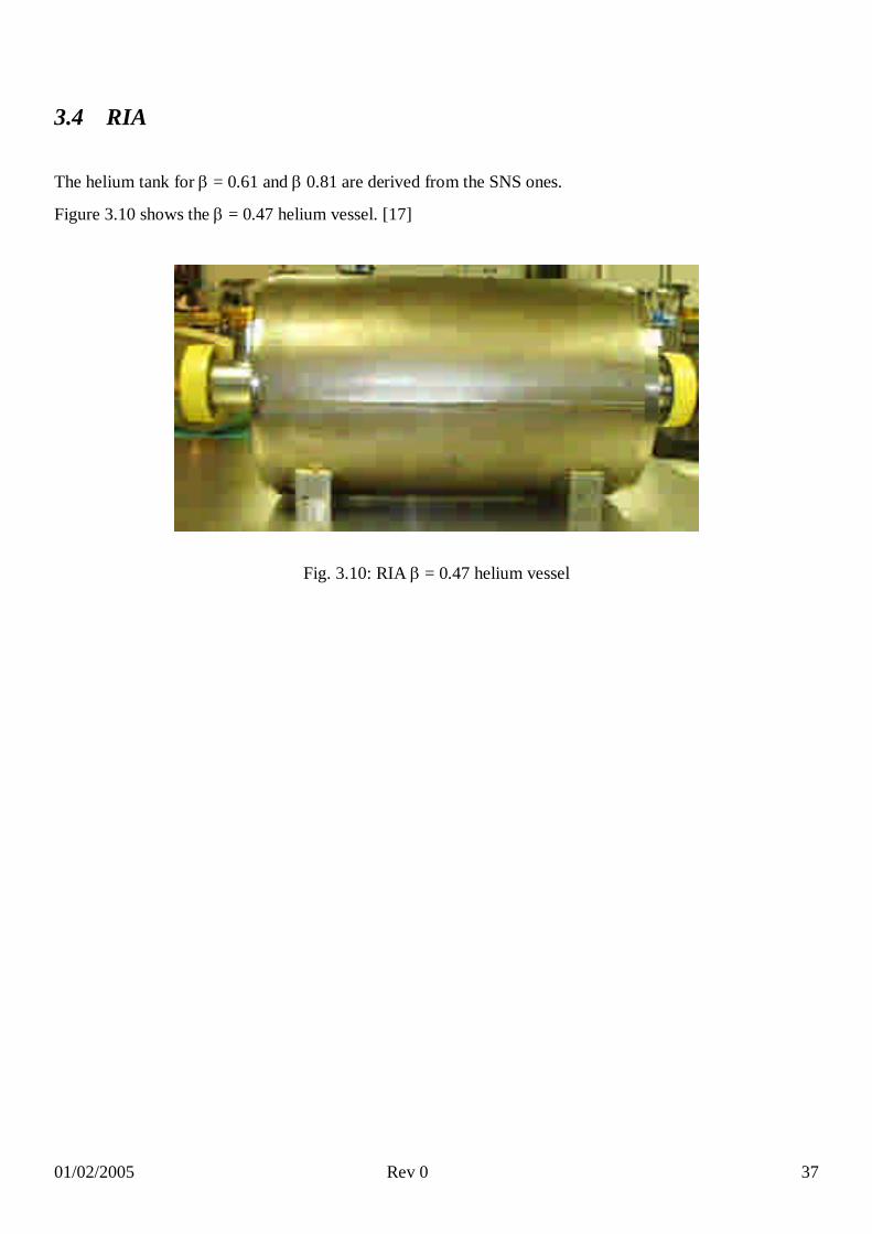
The helium tank for = 0.61 and 0.81 are derived from the SNS ones.
Figure 3.10 shows the = 0.47 helium vessel. [17]
Fig. 3.10: RIA = 0.47 helium vessel

01/02/2005 Rev 0 38
3.5 European ADS program: TRASCO and XADS
3.5.1 TRASCO
TRASCO = 0.47 5 cell cavity was tested only in a vertical cryostat, without any helium tank.
The helium tank is under design. The foreseen main parameters are reported in the next table.
He VESSELMaterial He vessel components Welding technique Assembly
procedureTuning system
Ti 2 Ti disk, NbTi ring, Ti tube Electron beam Under design Coaxial, under design
Tab 3.4: TRASCO = 0.47 5 cell cavity helium vessel.

01/02/2005 Rev 0 39
3.5.2 XADS
R&D on 700 MHz 5-cell proton cavities, =0.65.
Stainless Steel He vessel, with a brazed interface between the niobium and the stainless steel.
Test to verify the brazing tightness between a Nb tube and SS have been done, in super fluid He. The results
have indicated that the maximal stresses at the brazing area are 150 N/mm2 (for Nb tube), 80 N/mm2 (for
70m Cu interface) and 60 N/mm2 (for the SS flange). An additional load of about 5000 N for each flange
have been added to simulate the cold tuning system. Moreover a minimal distance of 9mm between the
copper brazed interface and the EB welding of the first cavity iris [32] have to be respected.
He VESSEL = 0.65 XADS
Cavity tuning parameters Technical and construction
FLorentz (Static longitudinal Lorentz Force)
f/L (longitudinal frequency sensitivity)
F/L(longitudinal cavity stiffness)
He vessel components
Welding technique
13.86 N About 250 kHz/mm
About 1592 N/mm SS tube, SS bellow, Cu interface for brazing
Brazing a SS He-tank on the Nb cavity (copper interface)
Request on New tank stiffening (considering also the CTS) [32]: About 20000 N/mm
Tab.3.5: XADS 700 MHz = 0.65 He vessel parameters.[32]
The XADS Helium tank is brazed to the Nb cavity and the description here reported is relative to Fig. .
The extremities, normalized 3 mm thick and 400 mm diameter domed cups (1), give a better stiffness than
conical ends. For a load applied on the beam tube the longitudinal stiffness can reach about 55 kN/mm,
which gives, associated with the cylindrical part of the vessel a total stiffness of about 50 kN /mm.
The SS parts (2) are brazed on the Niobium cut off at a minimal distance of 9 mm from the nearest EB
welds. The thickness of these rings is 15 mm to reduce the hoop thermal stresses at the copper interface
without over stressing the niobium tube . The de coupling bellow (3) allows 6 mm displacement. Four
supports (4) are welded close to the external diameter of the cups (where the tank stiffness is higher) to fix
the CTS. The vessel (5), 400 mm diameter, is as close as possible to the cavity equators to limit the volume

01/02/2005 Rev 0 40
available for helium inventory. A 40 mm CF cryogenic port onto the tank (6) is used for the feeding of super
fluid helium from an auxiliary pot. Two 16 mm CF ports (7,8) at the bottom of the tank are respectively
dedicated to the cool down of the cavity and the relation to the auxiliary pot for the LHe level
measurements. [4]
Fig. 3.11:.XADS Helium vessel sketch and picture [32].
Fig. 3.12 Single cell = 0.65 with the SS He-tank end caps [32]

01/02/2005 Rev 0 41
4 Cold flanges and sealing
The choice of the cold connection in superconducting accelerator is a critical point.
A cold connection must have the following characteristics: extremely low leak rate (also at low
temperature), reliable behaviour (also during thermal cycles), easy to assembly procedure, compatible with
clean room environment, cleanable, and finally cheap.
In this document are reported a retrieving of cold connection system used in superconducting accelerators:
for every machine a schedule is shown to summarize, for each kind of flanges, the main constructive
parameters as the closing torque, the material and the shape of the seal; together with the technical
drawings.
Also commercial flanges and seals are used in SC cavity: we collected some information about Conflat CF
flanges and Helicoflex.

01/02/2005 Rev 0 42
4.1 TESLA - TTF
TTF Beam flange
TTF Beam flange male
Material NbTi
O.D. 140.0 mm
Thickness 17.5 mm
Number of holes 12
Bolt circle diameter 120.0 mm
Groove depth 1.0 mm
External groove diameter
109.2 mm
Screw Stud bolt M8 1.4429 (Germany W.N.17007) or X 2 CrNiMoN 17 13 3 (DIN 17006)
Nut CuNiSil - Cu5 (DIN 17 672)
Washer A4 both sides (UNI 5962)
Closing torque 28-30 Nm
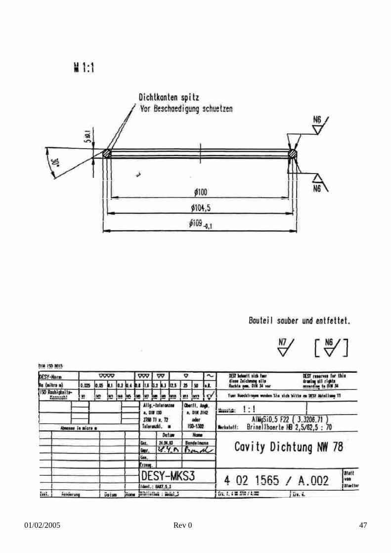
Seal AlMgSi 0,5 Diamond shape (DIN 1746)
Pipe connection Electron beam welding

01/02/2005 Rev 0 43

01/02/2005 Rev 0 44
TTF Beam flange female
Material
O.D. 140.6 mm
Thickness 19.6 mm
Groove depth 1.9 mm
Internal groove diameter
96.0 mm
External groove diameter
109.2mm
Number of holes 12
Bolt circle diameter 120 mm
Screw Stud bolt M8 1.4429 (Germany W.N.17007) or X 2 CrNiMoN 17 13 3 (DIN 17006)
Nut CuNiSil - Cu5 (DIN 17 672)
Washer A4 both sides (UNI 5962)
Closing torque 28-30 Nm
Seal AlMgSi 0,5 Diamond shape (DIN 1746)

01/02/2005 Rev 0 45

01/02/2005 Rev 0 46
I-DEAS model file: desy_cry3.mf1 – INFN Milan
01/02/2005 Rev 0 47
01/02/2005 Rev 0 48
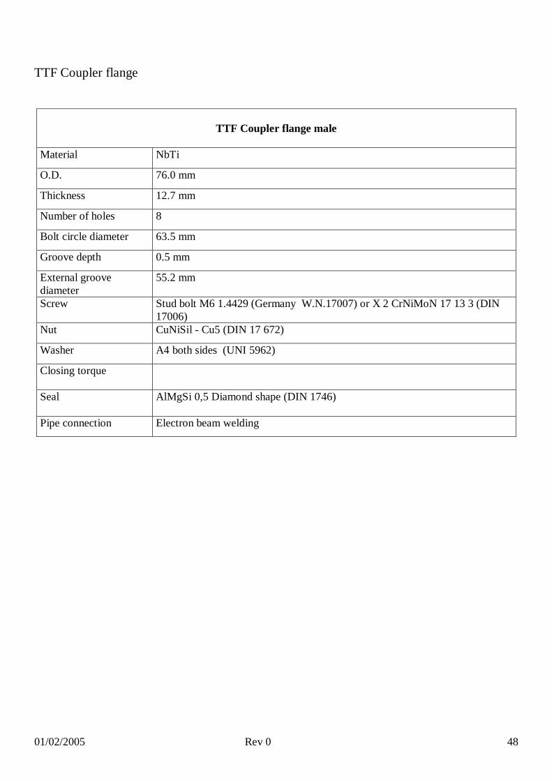
TTF Coupler flange
TTF Coupler flange male
Material NbTi
O.D. 76.0 mm
Thickness 12.7 mm
Number of holes 8
Bolt circle diameter 63.5 mm
Groove depth 0.5 mm
External groove diameter
55.2 mm
Screw Stud bolt M6 1.4429 (Germany W.N.17007) or X 2 CrNiMoN 17 13 3 (DIN 17006)
Nut CuNiSil - Cu5 (DIN 17 672)
Washer A4 both sides (UNI 5962)
Closing torque
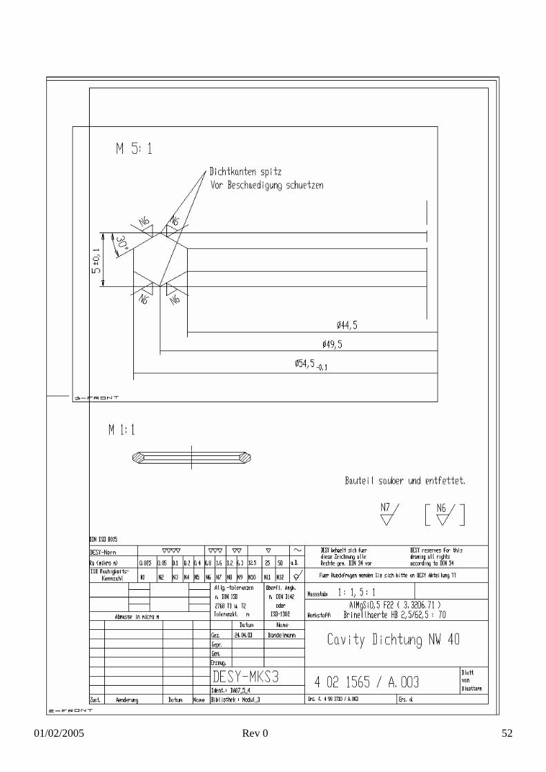
Seal AlMgSi 0,5 Diamond shape (DIN 1746)
Pipe connection Electron beam welding

01/02/2005 Rev 0 49
01/02/2005 Rev 0 50
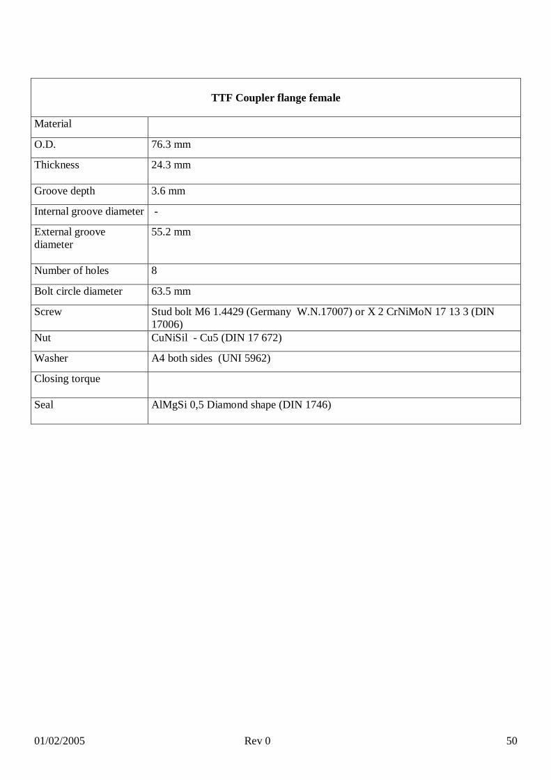
TTF Coupler flange female
Material
O.D. 76.3 mm
Thickness 24.3 mm
Groove depth 3.6 mm
Internal groove diameter -
External groove diameter
55.2 mm
Number of holes 8
Bolt circle diameter 63.5 mm
Screw Stud bolt M6 1.4429 (Germany W.N.17007) or X 2 CrNiMoN 17 13 3 (DIN 17006)
Nut CuNiSil - Cu5 (DIN 17 672)
Washer A4 both sides (UNI 5962)
Closing torque
Seal AlMgSi 0,5 Diamond shape (DIN 1746)

01/02/2005 Rev 0 51
I-DEAS model file: desy_cry3.mf1 – INFN Milan
01/02/2005 Rev 0 52
01/02/2005 Rev 0 53
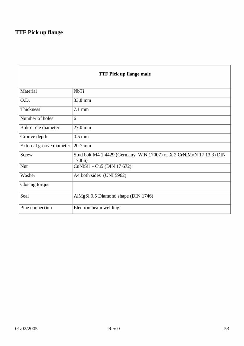
TTF Pick up flange
TTF Pick up flange male
Material NbTi
O.D. 33.8 mm
Thickness 7.1 mm
Number of holes 6
Bolt circle diameter 27.0 mm
Groove depth 0.5 mm
External groove diameter 20.7 mm
Screw Stud bolt M4 1.4429 (Germany W.N.17007) or X 2 CrNiMoN 17 13 3 (DIN 17006)
Nut CuNiSil - Cu5 (DIN 17 672)
Washer A4 both sides (UNI 5962)
Closing torque
Seal AlMgSi 0,5 Diamond shape (DIN 1746)
Pipe connection Electron beam welding

01/02/2005 Rev 0 54

01/02/2005 Rev 0 55
TTF Pick Up flange female
Material
O.D. 34.2 mm
Thickness 8.5 mm
Groove depth 1.0 mm
Internal groove diameter
9.3 mm
External groove diameter
20.7 mm
Number of holes 6
Bolt circle diameter 27.0 mm
Screw Stud bolt M8 1.4429 (Germany W.N.17007) or X 2 CrNiMoN 17 13 3 (DIN 17006)
Nut CuNiSil - Cu5 (DIN 17 672)
Washer A4 both sides (UNI 5962)
Closing torque
Seal AlMgSi 0,5 Diamond shape (DIN 1746)

01/02/2005 Rev 0 56
I-DEAS model file: desy_cry3.mf1 – INFN Milan

01/02/2005 Rev 0 57

01/02/2005 Rev 0 58
4.2 SNS
SNS Beam flange
SNS Beam flange male
Material NbTi
O.D. 124.2 mm (4.889”)
Thickness 25.4 mm (1.0”)
Number of holes 12
Bolt circle diameter 108.3 mm (4.264”)
Groove depth 1.0 mm (0.041”)
External groove diameter 97.6 mm (3.843”)
Screw A286 (A66286 UNS INCOLOY) 5/16” – 24 [33]
Nut Si Br [33]
Washer Yes + Belleville [33]
Closing torque 49.5 Nm ( 348 inch lbs.) [33]
Seal AlMg3 Diamond shape (DIN 1746)
Pipe connection Electron beam welding

01/02/2005 Rev 0 59

01/02/2005 Rev 0 60
SNS Beam flange female (blank flange)
Material Stainless steel type 304
O.D. 124.7 mm (4.908”)
Thickness 15.5 mm (0.611”)
Groove depth 3.1 mm (0.121”)
Internal groove diameter 85.3 mm (3.359”)
External groove diameter 97.6 mm (3.843”)
Number of holes 12
Bolt circle diameter 108.3 mm (4.264”)
Screw A286 (A66286 UNS INCOLOY) 5/16” – 24 [33]
Nut Si Br [33]
Washer Yes + Belleville [33]
Closing torque 49.5 Nm ( 348 inch lbs.) [33]
Seal AlMg3 Diamond shape (DIN 1746)

01/02/2005 Rev 0 61

01/02/2005 Rev 0 62
01/02/2005 Rev 0 63
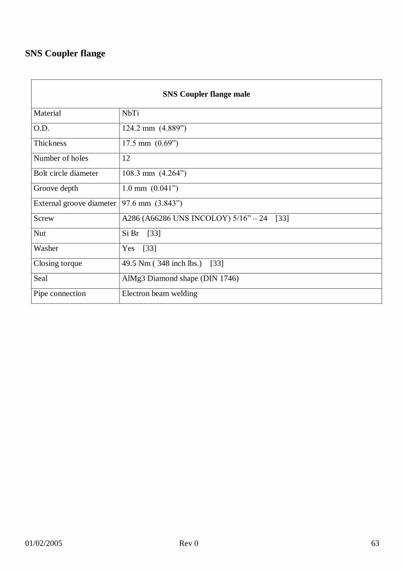
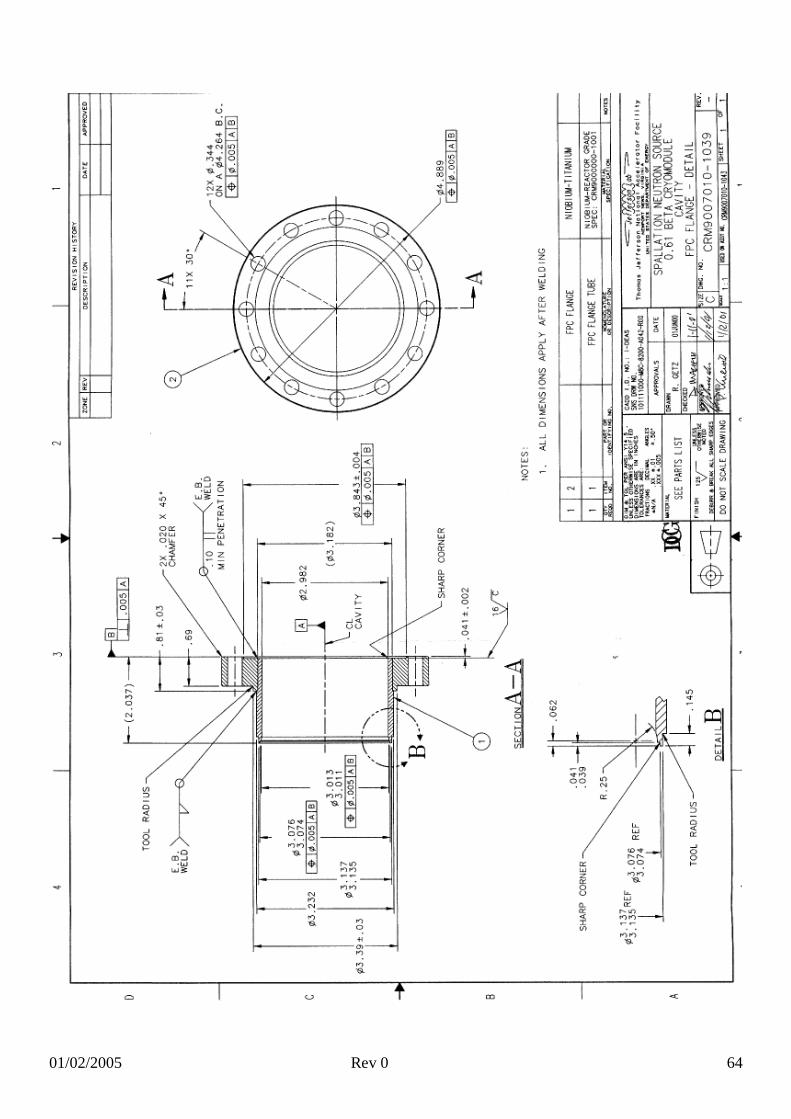
SNS Coupler flange
SNS Coupler flange male
Material NbTi
O.D. 124.2 mm (4.889”)
Thickness 17.5 mm (0.69”)
Number of holes 12
Bolt circle diameter 108.3 mm (4.264”)
Groove depth 1.0 mm (0.041”)
External groove diameter 97.6 mm (3.843”)
Screw A286 (A66286 UNS INCOLOY) 5/16” – 24 [33]
Nut Si Br [33]
Washer Yes [33]
Closing torque 49.5 Nm ( 348 inch lbs.) [33]
Seal AlMg3 Diamond shape (DIN 1746)
Pipe connection Electron beam welding
01/02/2005 Rev 0 64

01/02/2005 Rev 0 65
SNS Coupler flange female (blank flange)
Material Stainless steel type 304
O.D. 124.7 mm (4.908”)
Thickness 15.5 mm (0.611”)
Groove depth 3.1 mm (0.121”)
Internal groove diameter 85.3 mm (3.359”)
External groove diameter 97.6 mm (3.843”)
Number of holes 12
Bolt circle diameter 108.3 mm (4.264”)
Screw A286 (A66286 UNS INCOLOY) 5/16” – 24 [33]
Nut Si Br [33]
Washer Yes [33]
Closing torque 49.5 Nm ( 348 inch lbs.) [33]
Seal AlMg3 Diamond shape (DIN 1746)

01/02/2005 Rev 0 66

01/02/2005 Rev 0 67

01/02/2005 Rev 0 68
SNS Pick up
SNS Pick up flange male
Material NbTi
O.D. 46.6 mm (1.835”)
Thickness 7.1 mm (0.28”)
Number of holes 12
Bolt circle diameter 39.6 mm (1.559”)
Groove depth 0.5 mm (0.021”)
External groove diameter
33.1 mm (1.305”)
Screw A286 (A66286 UNS INCOLOY) 8-32 [33]
Nut Backer ring Al Ni Br [33]
Washer Yes + Belleville [33]
Closing torque 5 Nm ( 40 inch lbs.) [33]
Seal AlMg3 Diamond shape (DIN 1746)
Pipe connection Electron beam welding

01/02/2005 Rev 0 69
This is the old version of the pick up flange. The current design foreseen a change for the number of screw holes, from 6 to 12. See technical draw of the blank flange of page 75.
01/02/2005 Rev 0 70
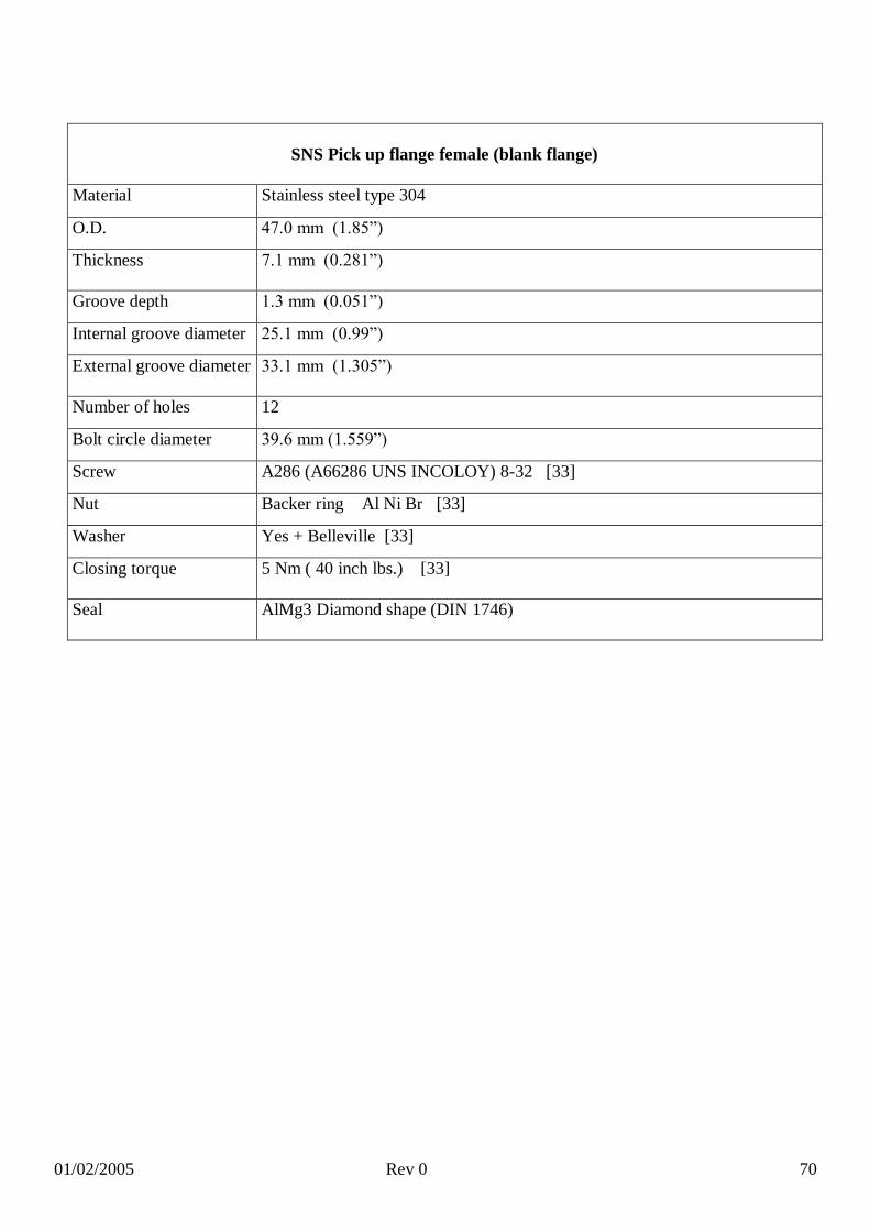
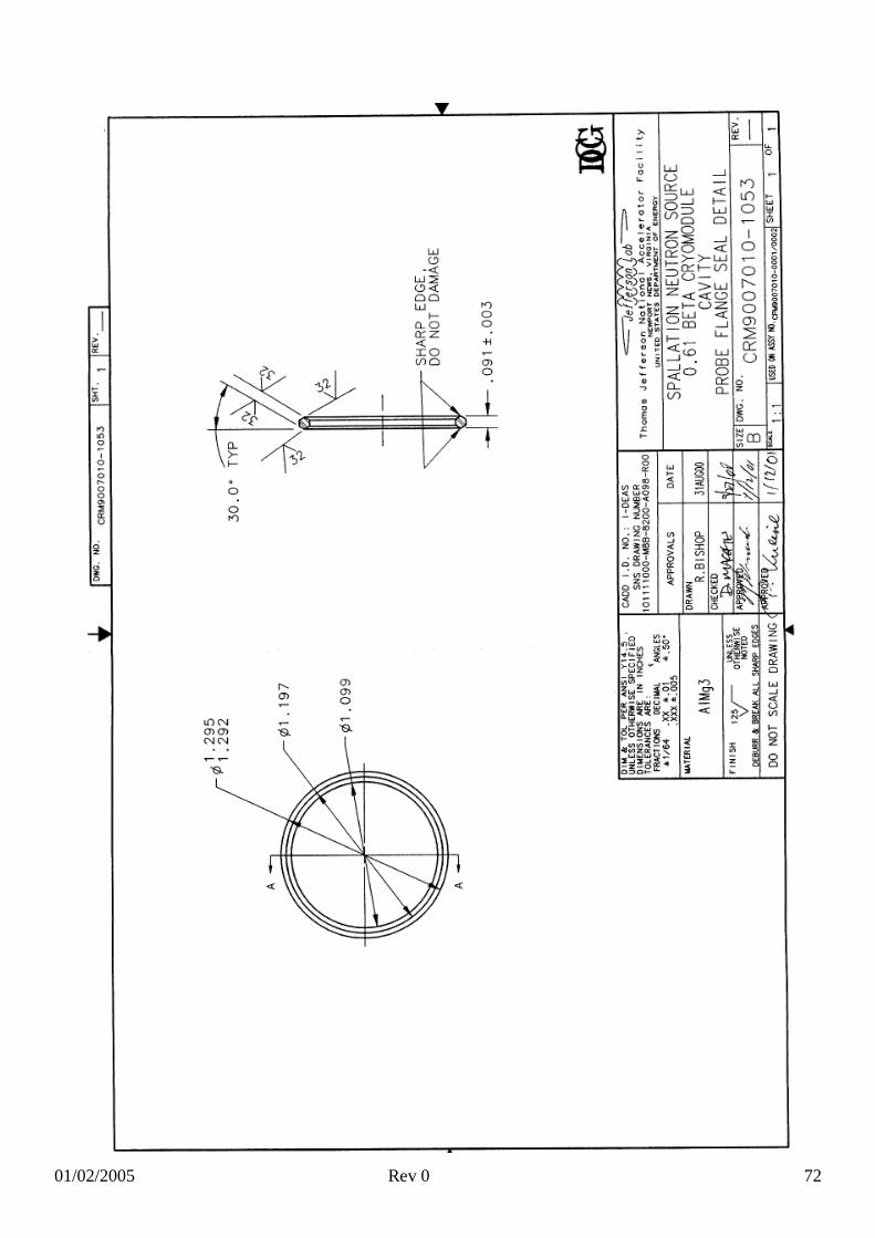
SNS Pick up flange female (blank flange)
Material Stainless steel type 304
O.D. 47.0 mm (1.85”)
Thickness 7.1 mm (0.281”)
Groove depth 1.3 mm (0.051”)
Internal groove diameter 25.1 mm (0.99”)
External groove diameter 33.1 mm (1.305”)
Number of holes 12
Bolt circle diameter 39.6 mm (1.559”)
Screw A286 (A66286 UNS INCOLOY) 8-32 [33]
Nut Backer ring Al Ni Br [33]
Washer Yes + Belleville [33]
Closing torque 5 Nm ( 40 inch lbs.) [33]
Seal AlMg3 Diamond shape (DIN 1746)

01/02/2005 Rev 0 71
01/02/2005 Rev 0 72

01/02/2005 Rev 0 73
4.3 TRASCO/XADS
TRASCO Beam flange
TRASCO Beam flange male
Material NbTi
O.D. 124.0 mm
Thickness 25.0 mm
Number of Holes 12
Bolt circle diameter 108.0 mm
Groove depth 1.0 mm
External groove diameter
98.0 mm
Screw M8 A4-80 (UNI EN ISO 3506-1)
Nut M8 A4-80 (UNI EN ISO 3506-1)
Washer A4 (UNI 5962)
Closing torque 30 Nm
Seal AlMg3 Diamond shape (DIN 1746)
Pipe connection Electron beam welding

01/02/2005 Rev 0 74

01/02/2005 Rev 0 75
TRASCO Beam flange female (blank flange)
Material AISI 316 LN
O.D. 124.4 mm
Thickness 20.0 mm
Groove depth 3.0 mm
Internal groove diameter 85.3 mm
External groove diameter 97.6 mm
Number of holes 12
Bolt circle diameter 108.0 mm
Screw M8 A4-80 (UNI EN ISO 3506-1)
Nut M8 A4-80 (UNI EN ISO 3506-1)
Washer A4 (UNI 5962)
Closing torque 30 Nm
Seal AlMg3 Diamond shape (DIN 1746)

01/02/2005 Rev 0 76

01/02/2005 Rev 0 77
TRASCO Main coupler
TRASCO Main coupler male
Material NbTi
O.D. 124.0 mm
Thickness 25.0 mm
Number of Holes 12
Bolt circle diameter 108.0 mm
Groove depth 1.0 mm
External groove diameter
98.0 mm
Screw M8 A4-80 (UNI EN ISO 3506-1)
Nut M8 A4-80 (UNI EN ISO 3506-1)
Washer A4 (UNI 5962)
Closing torque 30 Nm
Seal AlMg3 Diamond shape (DIN 1746)
Pipe connection Electron beam welding

01/02/2005 Rev 0 78

01/02/2005 Rev 0 79
TRASCO Coupler flange female (blank flange)
Material AISI 316 LN
O.D. 124.4 mm
Thickness 20.0 mm
Groove depth 3.0 mm
Internal groove diameter 85.3 mm
External groove diameter 97.6 mm
Number of holes 12
Bolt circle diameter 108.0 mm
Screw M8 A4-80 (UNI EN ISO 3506-1)
Nut M8 A4-80 (UNI EN ISO 3506-1)
Washer A4 (UNI 5962)
Closing torque 30 Nm
Seal AlMg3 Diamond shape (DIN 1746)
01/02/2005 Rev 0 80
01/02/2005 Rev 0 81
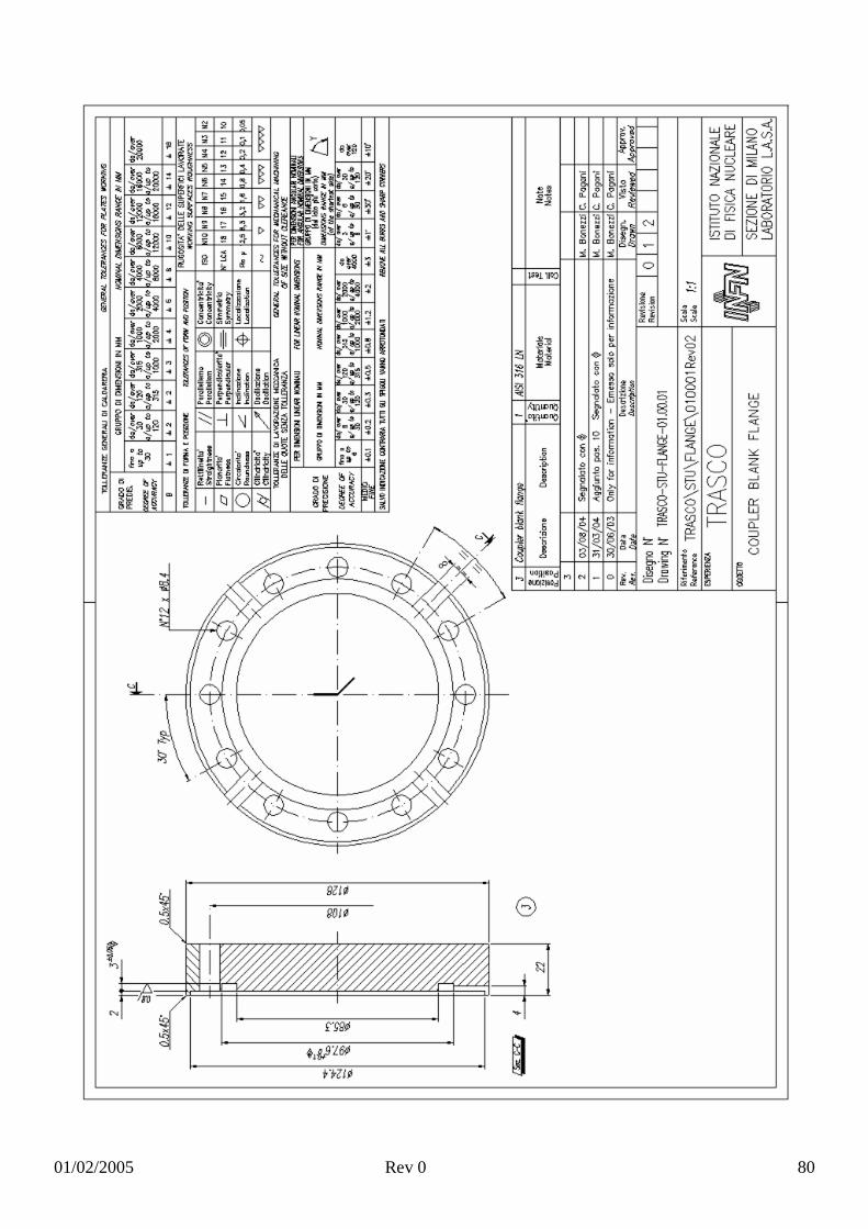
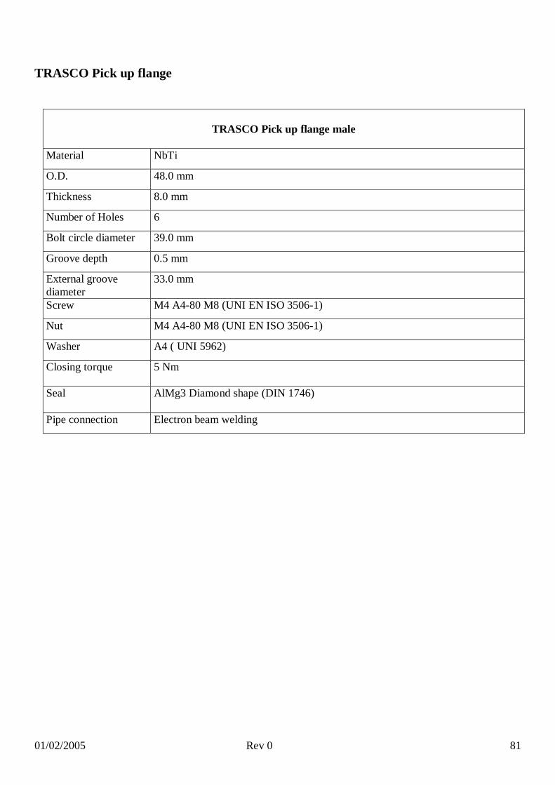
TRASCO Pick up flange
TRASCO Pick up flange male
Material NbTi
O.D. 48.0 mm
Thickness 8.0 mm
Number of Holes 6
Bolt circle diameter 39.0 mm
Groove depth 0.5 mm
External groove diameter
33.0 mm
Screw M4 A4-80 M8 (UNI EN ISO 3506-1)
Nut M4 A4-80 M8 (UNI EN ISO 3506-1)
Washer A4 ( UNI 5962)
Closing torque 5 Nm
Seal AlMg3 Diamond shape (DIN 1746)
Pipe connection Electron beam welding

01/02/2005 Rev 0 82
TRASCO Pick up flange female (blank flange)
Material AISI 316 LN
O.D. 48.3 mm
Thickness 15.0 mm
Groove depth 1.3 mm
Internal groove diameter 25.2 mm
External groove diameter 33.0 mm
Number of holes 6
Bolt circle diameter 39.0 mm
Screw M4 A4-80 M8 (UNI EN ISO 3506-1)
Nut M4 A4-80 M8 (UNI EN ISO 3506-1)
Washer A4 ( UNI 5962)
Closing torque 5 Nm
Seal AlMg3 Diamond shape (DIN 1746)

01/02/2005 Rev 0 83

01/02/2005 Rev 0 84
4.4 Commercial cold connectionIn the retrieving of information two kinds of commercial flanges and seals are been taken in account:
Conflat CF flanges and Helicoflex.
CONFLAT® (CF FLANGES, ISO DIS 3669)
Usual CF flanges can be used also at cryogenic temperature (see for instance the Varian catalogue).
CF flanges
CF 16 CF 40 CF 100
Material 316 LN 316 LN 316 LN
O.D. 34.0 mm 69.5 mm 152.0 mm
Bolt circle diameter K 27.0 mm 58.7 mm 130.3 mm
h 7.5 mm 13.0 mm 20.0 mm
Number of holes 6 6 16
Bolt M4 X 20 M6 X 35 M8 X 50
Suggested closing torque
4 Nm 10 Nm 20 Nm
Seal copper gasket copper gasket copper gasket
Connection to Nb pipe brazing brazing brazing
LEYBOLD catalogue 2003-04 page C15.03

01/02/2005 Rev 0 85
Helicoflex
Helicoflex are special metal gaskets, produced by Garlok, which can be used for UHV connections, also
operating al cryogenic temperatures. The same company produce also special quick disconnect systems.
Helicoflex gaskets were used in SC cavities but, in some cases, they had shown some drawback like
difficulties in cleaning the internal spring. [34]
Detailed information of the Helicoflex seals characteristics and suggestions for the correct use can be found
on the web: www.helicoflex.com/.

01/02/2005 Rev 0 86

01/02/2005 Rev 0 87
References
1] A. Bosotti et al., RF tests of the beta = 0.5 five cells TRASCO cavities, EPAC 2004.2] P. Kneisel, G. Ciovati, RF Test of a 5-cell βg=0.47 cavity for the TRASCO project.3] D. Barni et al., RF tests of the single cell prototypes for the TRASCO =0.47 cavities, EPAC 2002.4] B. Visentin et al, Experimental result on 700 MHZ multi cell superconducting cavity for proton
linac, PAC2003.5] M. Liepe, Pulsed superconductivity acceleration, LINAC 2000..6] TESLA TDR Chapter 2.7] H. Gassot, Mechanical stability of the RF superconducting cavities, EPAC2002.8] B. Aune et al., Superconducting TESLA cavities, PRST, Accelerator and beams, Vol. 3, 092001
(2000).9] S. Bousson et al., An alternative scheme for stiffening SRF cavities by plasma spraying, PAC1999.10] S. Bousson et al., Inert gaz plasma spraying for cavity stiffening using copper coating, SRF2001.11] P. Sekalski et al., Lorentz force detuning compensation system for the accelerating field gradients up
to 35 MV/m for superconducting X-FEL and TESLA nine-cell cavities, CARE-CONF-04-001-SRF.12] P. Kneisel, SC linac cavity physics, talk,
https://www.sns.gov/APGroup/ Minutes/ColabMinutes/001024_Kneisel.pdf.13] G. Ciovati et al., Superconducting prototype cavities for the spallation neutron source (SNS) project,
SRF 2001.14] G. Ciovati et al., Superconducting prototype cavities for the spallation neutron source (SNS) project,
PAC 2001.15] G. Ciovati et al., Superconducting prototype cavities for the spallation neutron source (SNS) project,
EPAC 2002.16] M. Pekeler et al., Superconducting cavity production and preparation at Accel Instruments GMBH,
SRF 2003.17] T. L. Grimm et al., Superconducting RF activities for the Rare Isotope Accelerator at Michigan State
University, SRF2003.18] W. Hartung et al., Status report on multi-cell superconducting cavity development for medium-
velocity beams, PAC2003.19] C.C. Compton et al., Niobium cavity development for the high-energy linac of the Rare Isotope
Accelerator, PAC2001.20] T. L. Grimm et al., experimental study of an 805 MHz cryomodule for the Rare Isotope Accelerator,
LINAC2004.21] T. L. Grimm et al., 805 MHz = 0.47 elliptical accelerating structure R&D,
http://www.oro.doe.gov/riaseb/wrkshop2003/papers/p-2-2-3.pdf.22] P. Pierini et al., Cavity design tools and applications to the TRASCO project, 9th Workshop RF
Superconductivity, 1999.23] D. Barni et al., SC cavity design for the 700 MHz TRASCO linac, EPAC 2000.24] C. Pagani, TTF Cryomodule operation experience, Talk at First ILC Work 2004.25] S. Bauer et al., Production of the superconducting 9 cells cavities for the TESLA test facility,
9th Workshop RF Superconductivity, 1999.26] E. F. Daly et al., Improved prototype cryomodule for the CEBAF 12 GeV upgrade, PAC2003.27] J. Delayen, Cryomodule development for the CEBAF upgrade, PAC1999.

01/02/2005 Rev 0 88
28] I. E. Campisi et al., CEBAF upgrade cryomodule component testing in the horizontal test bed (HTB), PAC2001.
29] H. Wang et al., HOM dumping performances of JLAB SL21 cryomodule, PAC2003.30] J. Hogan et al., Design of the SNS cavity support structure, PAC2001.31] H. Padamsee, RF superconductivity – 2004, SRF 2004.32] H. Saugnac et al,. Preliminary design of a stainless steel helium tank and its associated cold tuning
system for 700 MHz SC RF cavities for proton, SRF2001.33] T. M. Rothgeb et al., Cyclic testing of the SNS DESY style seal, JLAB-TN-02-052.34] K. Zapfe et al., A new flange design for superconducting cavities for TESLA, 8th Workshop on RF
superconductivity, Abano Terme, 1997.