ms2690a-020/ms2691a-020/ms2692a-020 vector · pdf filems2690a-020/ms2691a-020/ms2692a-020...
TRANSCRIPT
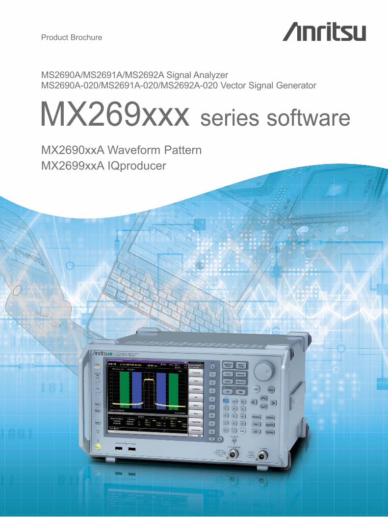
Product Brochure
MX2690xxA Waveform PatternMX2699xxA IQproducer
MX269xxx series softwareMS2690A/MS2691A/MS2692A Signal AnalyzerMS2690A-020/MS2691A-020/MS2692A-020 Vector Signal Generator
3GP
PLT
E (
FD
D)
Multi-carrier IQproducer is software that generates the multi-carrier signal based on waveform patterns ofvarious telecommunications systems.
2
MX269xxx Series Software
MS269xA Signal Analyzer family supports a built-in Vector Signal Generator. The addition of the MS269xA-020, VectorSignal Generator option to the MS269xA Signal Analyzer creates a powerful one-box tester that can be configured tosupport various communication technologies. From R&D to the factory floor, this powerful combination of SignalAnalyzer and Signal Generator can meet and exceed test and measurement needs. Files containing waveform patternscorresponding to either well-known standards or theoretical simulations can be loaded, selected, and played to createan endless number of waveforms.
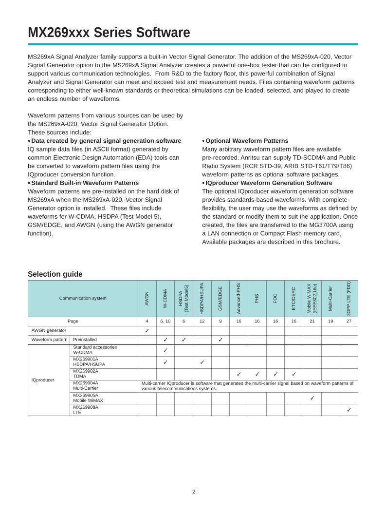
Selection guide
Communication system
Mul
ti-C
arrie
r
Mob
ile W
iMA
X(I
EE
E80
2.16
e)
ET
C/D
SR
C
PD
C
PH
S
Adv
ance
d-P
HS
GS
M/E
DG
E
HS
DP
A/H
SU
PA
HS
DP
A(T
est
Mod
el5)
W-C
DM
A
AW
GN
Page
Preinstalled
Standard accessories W-CDMA
MX269901AHSDPA/HSUPA
MX269902ATDMA
MX269904AMulti-Carrier
MX269905AMobile WiMAX
Waveform pattern
AWGN generator
IQproducer
66, 104 12 9 16 16 16 16 21 19
MX269908ALTE
27
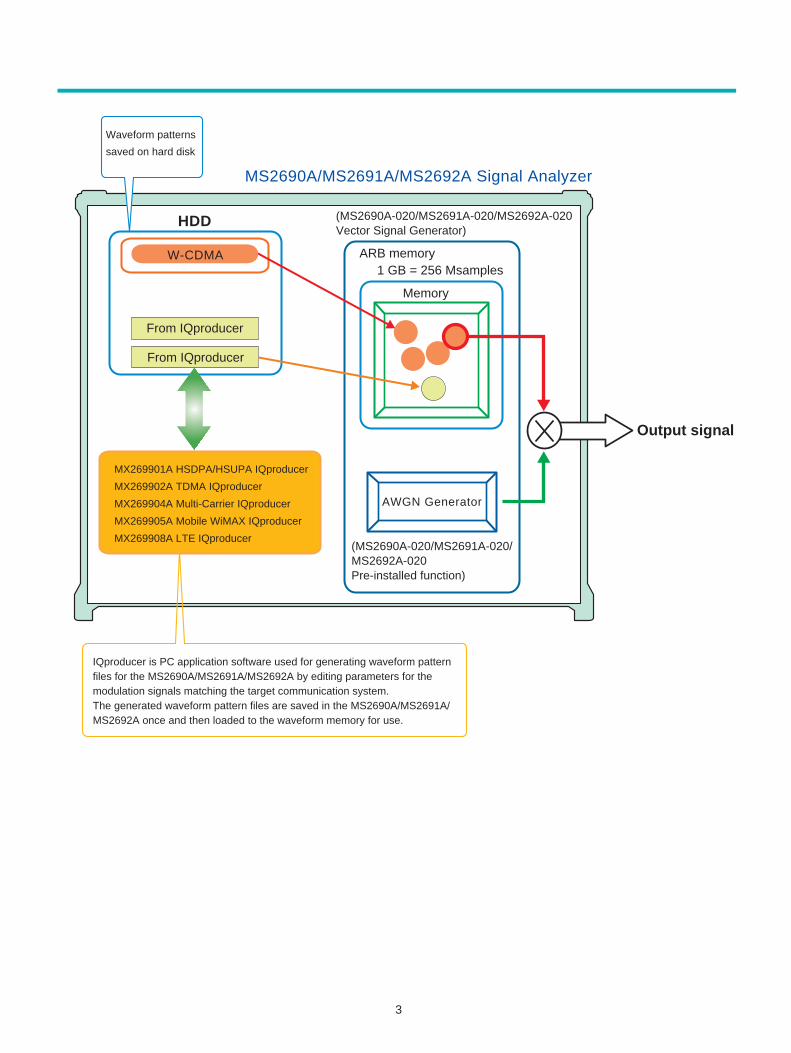
Waveform patterns from various sources can be used bythe MS269xA-020, Vector Signal Generator Option. These sources include:• Data created by general signal generation softwareIQ sample data files (in ASCII format) generated bycommon Electronic Design Automation (EDA) tools canbe converted to waveform pattern files using theIQproducer conversion function. • Standard Built-in Waveform PatternsWaveform patterns are pre-installed on the hard disk ofMS269xA when the MS269xA-020, Vector SignalGenerator option is installed. These files include waveforms for W-CDMA, HSDPA (Test Model 5),GSM/EDGE, and AWGN (using the AWGN generatorfunction).
• Optional Waveform Patterns Many arbitrary waveform pattern files are available pre-recorded. Anritsu can supply TD-SCDMA and PublicRadio System (RCR STD-39, ARIB STD-T61/T79/T86)waveform patterns as optional software packages.• IQproducer Waveform Generation Software The optional IQproducer waveform generation softwareprovides standards-based waveforms. With completeflexibility, the user may use the waveforms as defined bythe standard or modify them to suit the application. Oncecreated, the files are transferred to the MG3700A usinga LAN connection or Compact Flash memory card.Available packages are described in this brochure.
3
HDD
Output signal
From IQproducer
From IQproducer
W-CDMA
Memory
MS2690A/MS2691A/MS2692A Signal Analyzer
ARB memory 1 GB = 256 Msamples
MX269901A HSDPA/HSUPA IQproducer
MX269902A TDMA IQproducer
MX269904A Multi-Carrier IQproducer
MX269905A Mobile WiMAX IQproducer
MX269908A LTE IQproducer
AWGN Generator
(MS2690A-020/MS2691A-020/MS2692A-020Pre-installed function)
(MS2690A-020/MS2691A-020/MS2692A-020 Vector Signal Generator)
Waveform patterns
saved on hard disk
IQproducer is PC application software used for generating waveform pattern files for the MS2690A/MS2691A/MS2692A by editing parameters for the modulation signals matching the target communication system.The generated waveform pattern files are saved in the MS2690A/MS2691A/MS2692A once and then loaded to the waveform memory for use.
4
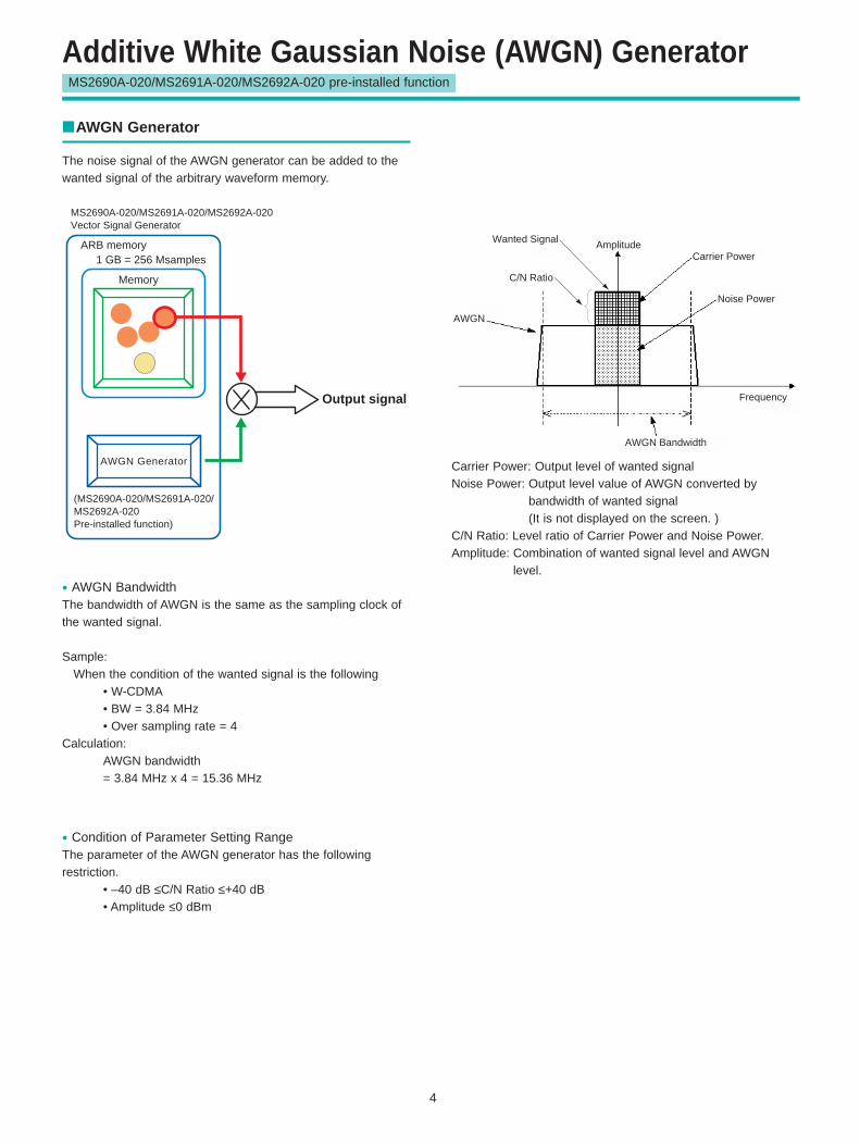
Additive White Gaussian Noise (AWGN) GeneratorMS2690A-020/MS2691A-020/MS2692A-020 pre-installed function
AWGN Generator
The noise signal of the AWGN generator can be added to thewanted signal of the arbitrary waveform memory.
Output signal
Memory
ARB memory 1 GB = 256 Msamples
AWGN Generator
(MS2690A-020/MS2691A-020/ MS2692A-020 Pre-installed function)
MS2690A-020/MS2691A-020/MS2692A-020 Vector Signal Generator
AWGN
C/N Ratio
Wanted Signal AmplitudeCarrier Power
Noise Power
Frequency
AWGN Bandwidth
Carrier Power: Output level of wanted signalNoise Power: Output level value of AWGN converted by
bandwidth of wanted signal (It is not displayed on the screen. )
C/N Ratio: Level ratio of Carrier Power and Noise Power.Amplitude: Combination of wanted signal level and AWGN
level.
• Condition of Parameter Setting RangeThe parameter of the AWGN generator has the followingrestriction.
• –40 dB ≤C/N Ratio ≤+40 dB• Amplitude ≤0 dBm
• AWGN BandwidthThe bandwidth of AWGN is the same as the sampling clock ofthe wanted signal.
Sample: When the condition of the wanted signal is the following
• W-CDMA• BW = 3.84 MHz• Over sampling rate = 4
Calculation:AWGN bandwidth= 3.84 MHz x 4 = 15.36 MHz
5
Additive White Gaussian Noise (AWGN) GeneratorMS2690A-020/MS2691A-020/MS2692A-020 pre-installed function
Display FunctionAWGN On/Off On, Off
Carrier, Noise, Constant
C/N Set SignalCarrier: Noise Power is a fixed value. Carrier Power is set. Noise: Carrier Power is a fixed value. Noise Power is set. Constant: Amplitude is a fixed value. Level ratio of C/N is set.
Carrier Power The output level of Carrier Power is set.
C/N RatioLevel ratio of Carrier Power and converted Noise Power is set.
–40 dB ≤ C/N Ratio ≤ +40 dB
• Parameter Setting Range
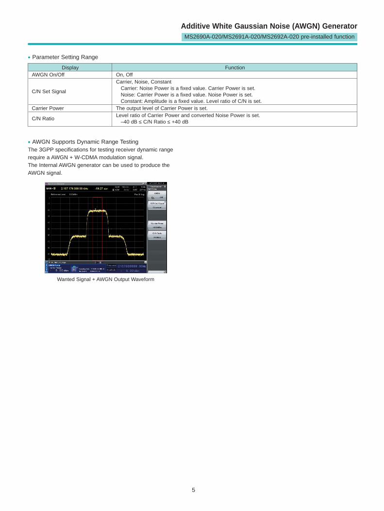
• AWGN Supports Dynamic Range TestingThe 3GPP specifications for testing receiver dynamic rangerequire a AWGN + W-CDMA modulation signal.The Internal AWGN generator can be used to produce theAWGN signal.
Wanted Signal + AWGN Output Waveform
6
W-CDMA Waveform PatternsStandard
W-CDMA Waveform Patterns
The following W-CDMA waveform patterns are installed on theinternal hard disk when MS269xA-020, Vector Signal GeneratorOption is installed. Details for each pattern file is given on thenext page.
• For Evaluating Base Station Transmitter Devices(TS 25.141 Test Model 1 to 4)
TestModel_1_16DPCHTestModel_1_32DPCHTestModel_1_64DPCHTestModel_1_64x2_10MTestModel_1_64x2_15MTestModel_2TestModel_3_16DPCHTestModel_3_32DPCHTestModel_4TestModel_5_2HSPDSCHTestModel_5_4HSPDSCHTestModel_5_8HSPDSCHTestModel_1_64DPCHx2TestModel_1_64DPCHx3TestModel_1_64DPCHx4DL_CPICH
• For Testing BS Receiver Performance(TS 25.101/ 25.104 UL RMC 12.2 to 384 kbps)
UL_RMC_12_2kbpsUL_RMC_64kbpsUL_RMC_144kbpsUL_RMC_384kbpsUL_AMR_TFCS1UL_AMR_TFCS2UL_AMR_TFCS3UL_ISDNUL_64kbps_PacketUL_Interfere
• For Evaluating UE Transmitter Devices(TS 25.101 A2.1)
UL_RMC_12_2kbps_TX
Uplink and downlink W-CDMA modulation signals conformingto the 3GPP (FDD) standards can be output simply by selecting the waveform from the patterns on the internal harddisk without setting any complex 3GPP-compliant parameters.
• For Testing UE Receiver Performance(TS 25.101 DL RMC 12.2 to 384 kbps)
DL_RMC_12_2kbps_RXDL_RMC_12_2kbpsDL_RMC_12_2kbps_MILDL_RMC_64kbpsDL_RMC_144kbpsDL_RMC_384kbpsDL_AMR_TFCS1DL_AMR_TFCS2DL_AMR_TFCS3DL_ISDNDL_384kbps_PacketDL_Interfere
7
Standard
W-CDMA Waveform Patterns
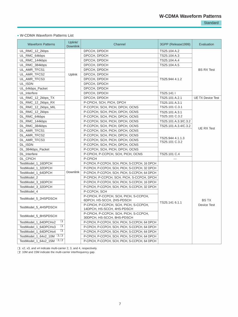
Waveform PatternsUplink/
DownlinkChannel 3GPP (Release1999) Evaluation
UL_RMC_12_2kbps DPCCH, DPDCH TS25.104 A.2
UL_RMC_64kbps DPCCH, DPDCH TS25.104 A.3
UL_RMC_144kbps DPCCH, DPDCH TS25.104 A.4
UL_RMC_384kbps DPCCH, DPDCH TS25.104 A.5
UL_AMR_TFCS1 DPCCH, DPDCH BS RX Test
UL_AMR_TFCS2 DPCCH, DPDCH
UL_AMR_TFCS3 DPCCH, DPDCH TS25.944 4.1.2
UL_ISDN DPCCH, DPDCH
UL_64kbps_Packet DPCCH, DPDCH
UL_Interfere DPCCH, DPDCH TS25.141 I
UL_RMC_12_2kbps_TX DPCCH, DPDCH TS25.101 A.2.1 UE TX Device Test
DL_RMC_12_2kbps_RX P-CPICH, SCH, PICH, DPCH TS25.101 A.3.1DL_RMC_12_2kbps_MIL P-CCPCH, SCH, PICH, DPCH, OCNS TS25.101 C.3.1
DL_RMC_12_2kbps P-CCPCH, SCH, PICH, DPCH, OCNS TS25.101 A.3.1DL_RMC_64kbps P-CCPCH, SCH, PICH, DPCH, OCNS TS25.101 C.3.2
DL_RMC_144kbps P-CCPCH, SCH, PICH, DPCH, OCNS TS25.101 A.3.3/C.3.2
DL_RMC_384kbps P-CCPCH, SCH, PICH, DPCH, OCNS TS25.101 A.3.4/C.3.2UE RX Test
DL_AMR_TFCS1 P-CCPCH, SCH, PICH, DPCH, OCNS
DL_AMR_TFCS2 P-CCPCH, SCH, PICH, DPCH, OCNSTS25.944 4.1.1.3
DL_AMR_TFCS3 P-CCPCH, SCH, PICH, DPCH, OCNS
DL_ISDN P-CCPCH, SCH, PICH, DPCH, OCNSTS25.101 C.3.2
DL_384kbps_Packet P-CCPCH, SCH, PICH, DPCH, OCNS
DL_Interfere P-CPICH, P-CCPCH, SCH, PICH, OCNS TS25.101 C.4
DL_CPICH P-CPICH —
TestModel_1_16DPCH P-CPICH, P-CCPCH, SCH, PICH, S-CCPCH, 16 DPCH
TestModel_1_32DPCH P-CPICH, P-CCPCH, SCH, PICH, S-CCPCH, 32 DPCH
TestModel_1_64DPCH P-CPICH, P-CCPCH, SCH, PICH, S-CCPCH, 64 DPCH
TestModel_2 P-CPICH, P-CCPCH, SCH, PICH, S-CCPCH, DPCH
TestModel_3_16DPCH P-CPICH, P-CCPCH, SCH, PICH, S-CCPCH, 16 DPCH
TestModel_3_32DPCH P-CPICH, P-CCPCH, SCH, PICH, S-CCPCH, 32 DPCH
TestModel_4 P-CCPCH, SCH
TestModel_5_2HSPDSCH P-CPICH, P-CCPCH, SCH, PICH, S-CCPCH,6DPCH, HS-SCCH, 2HS-PDSCH BS TX
TestModel_5_4HSPDSCH P-CPICH, P-CCPCH, SCH, PICH, S-CCPCH,
TS25.141 6.1.1Device Test
14DPCH, HS-SCCH, 4HS-PDSCH
TestModel_5_8HSPDSCH P-CPICH, P-CCPCH, SCH, PICH, S-CCPCH, 30DPCH, HS-SCCH, 8HS-PDSCH
TestModel_1_64DPCHx2 ∗ 1 P-CPICH, P-CCPCH, SCH, PICH, S-CCPCH, 64 DPCH
TestModel_1_64DPCHx3 ∗ 1 P-CPICH, P-CCPCH, SCH, PICH, S-CCPCH, 64 DPCH
TestModel_1_64DPCHx4 ∗ 1 P-CPICH, P-CCPCH, SCH, PICH, S-CCPCH, 64 DPCH
TestModel_1_64x2_10M ∗ 1,∗ 2 P-CPICH, P-CCPCH, SCH, PICH, S-CCPCH, 64 DPCH
TestModel_1_64x2_15M ∗ 1,∗ 2 P-CPICH, P-CCPCH, SCH, PICH, S-CCPCH, 64 DPCH
Uplink
Downlink
• W-CDMA Waveform Patterns List
∗ 1: x2, x3, and x4 indicate multi-carrier 2, 3, and 4, respectively.
∗ 2: 10M and 15M indicate the multi-carrier interfrequency gap.
8
Standard
W-CDMA Waveform Patterns
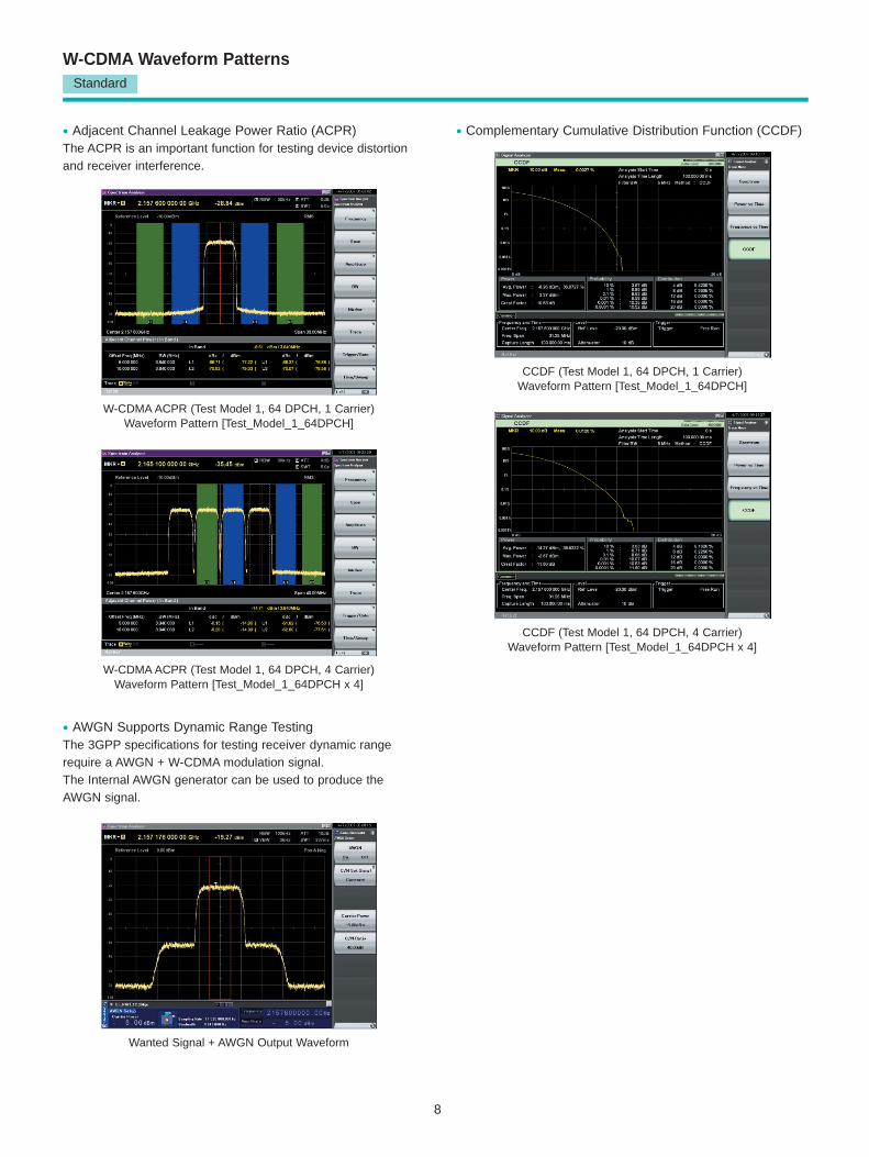
• Adjacent Channel Leakage Power Ratio (ACPR)The ACPR is an important function for testing device distortionand receiver interference.
• Complementary Cumulative Distribution Function (CCDF)
W-CDMA ACPR (Test Model 1, 64 DPCH, 1 Carrier)Waveform Pattern [Test_Model_1_64DPCH]
W-CDMA ACPR (Test Model 1, 64 DPCH, 4 Carrier)Waveform Pattern [Test_Model_1_64DPCH x 4]
CCDF (Test Model 1, 64 DPCH, 1 Carrier)Waveform Pattern [Test_Model_1_64DPCH]
CCDF (Test Model 1, 64 DPCH, 4 Carrier)Waveform Pattern [Test_Model_1_64DPCH x 4]
• AWGN Supports Dynamic Range TestingThe 3GPP specifications for testing receiver dynamic rangerequire a AWGN + W-CDMA modulation signal.The Internal AWGN generator can be used to produce theAWGN signal.
Wanted Signal + AWGN Output Waveform
9
GSM/EDGE Waveform PatternsStandard
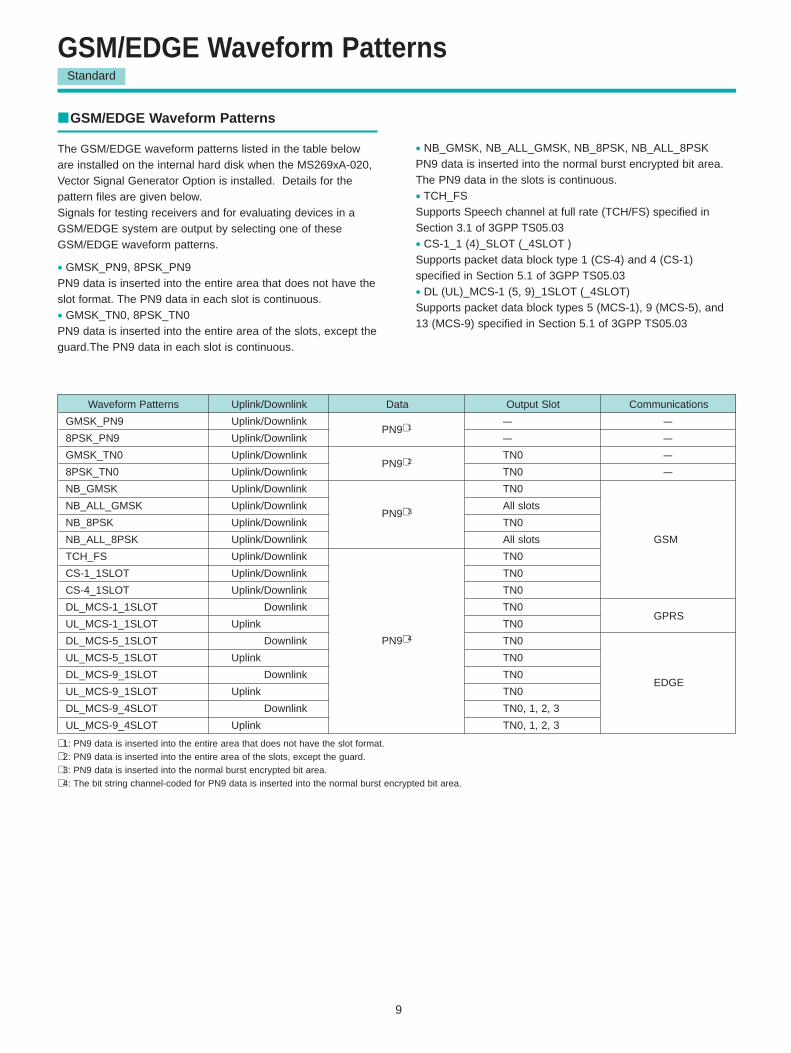
Waveform Patterns Uplink/Downlink Data Output Slot Communications
GMSK_PN9 Uplink/Downlink – –
8PSK_PN9 Uplink/Downlink – –
GMSK_TN0 Uplink/Downlink TN0 –
8PSK_TN0 Uplink/Downlink TN0 –
NB_GMSK Uplink/Downlink TN0
NB_ALL_GMSK Uplink/Downlink All slots
NB_8PSK Uplink/Downlink TN0
NB_ALL_8PSK Uplink/Downlink All slots GSM
TCH_FS Uplink/Downlink TN0
CS-1_1SLOT Uplink/Downlink TN0
CS-4_1SLOT Uplink/Downlink TN0
DL_MCS-1_1SLOT Uplink Downlink TN0
UL_MCS-1_1SLOT Uplink / Downlink TN0GPRS
DL_MCS-5_1SLOT Uplink Downlink TN0
UL_MCS-5_1SLOT Uplink / Downlink TN0
DL_MCS-9_1SLOT Uplink Downlink TN0EDGE
UL_MCS-9_1SLOT Uplink / Downlink TN0
DL_MCS-9_4SLOT Uplink Downlink TN0, 1, 2, 3
UL_MCS-9_4SLOT Uplink / Downlink TN0, 1, 2, 3
GSM/EDGE Waveform Patterns
The GSM/EDGE waveform patterns listed in the table beloware installed on the internal hard disk when the MS269xA-020,Vector Signal Generator Option is installed. Details for the pattern files are given below.Signals for testing receivers and for evaluating devices in aGSM/EDGE system are output by selecting one of theseGSM/EDGE waveform patterns.
• GMSK_PN9, 8PSK_PN9PN9 data is inserted into the entire area that does not have theslot format. The PN9 data in each slot is continuous.
• GMSK_TN0, 8PSK_TN0PN9 data is inserted into the entire area of the slots, except theguard.The PN9 data in each slot is continuous.
∗ 1: PN9 data is inserted into the entire area that does not have the slot format.∗ 2: PN9 data is inserted into the entire area of the slots, except the guard.∗ 3: PN9 data is inserted into the normal burst encrypted bit area.∗ 4: The bit string channel-coded for PN9 data is inserted into the normal burst encrypted bit area.
PN9∗ 3
PN9∗ 4
PN9∗ 1
PN9∗ 2
• NB_GMSK, NB_ALL_GMSK, NB_8PSK, NB_ALL_8PSKPN9 data is inserted into the normal burst encrypted bit area.The PN9 data in the slots is continuous.
• TCH_FSSupports Speech channel at full rate (TCH/FS) specified inSection 3.1 of 3GPP TS05.03
• CS-1_1 (4)_SLOT (_4SLOT )Supports packet data block type 1 (CS-4) and 4 (CS-1)specified in Section 5.1 of 3GPP TS05.03
• DL (UL)_MCS-1 (5, 9)_1SLOT (_4SLOT)Supports packet data block types 5 (MCS-1), 9 (MCS-5), and13 (MCS-9) specified in Section 5.1 of 3GPP TS05.03
10
W-CDMA IQproducerStandard accessory
W-CDMA IQproducer
W-CDMA IQproducer is GUI-based, PC application software forgenerating waveform patterns used in W-CDMA Rx sensitivitymeasurement. Once created, the waveform pattern file is downloaded to the MS269xA hard drive. Using the MS269xA-020,Vector Signal Generator Option functionality, the files areloaded, selected, and output as a modulated RF signal.By changing the Scrambling Code Number and ChannelizationCode Number, waveform patterns can be created that supportthe evaluation of W-CDMA terminals.If complete control of all W-CDMA parameters is required, theMX269901A HSDPA/HSUPA IQproducer software (sold separately) can be used. For details, see the MX269901AHSDPA/HSUPA IQproducer section of this document.
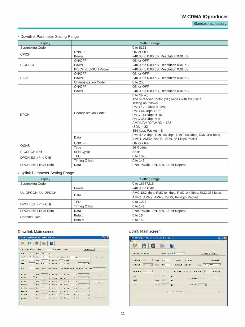
• Downlink SettingsDownlink sets parameters including Scrambling code,CPICH/P-CCPCH/PICH/DPCH power, Channelization code,DPCH_PhyCH TFCI and Timing Offset, and DPCH_TrCH Datato create the waveform pattern. (For details, see the DownlinkParameter Setting Range table described later.)Additionally, the Downlink Easy Setup function supports theReference Measurement Channel (RMC) items specified by3GPP TS25.101 and TS25.104. Parameter setting is easy justby selecting the items to create the waveform pattern.
Easy Setup Items include:RMC 12.2 kbps (RX test)RMC 12.2 kbps (Performance test)RMC 64 kbps (Performance test)RMC 144 kbps (Performance test)RMC 384 kbps (Performance test)
• Uplink SettingsUplink sets parameters including Scrambling code, UL-DPCCH/UL-DPDCH power, DPCH_PhyCH TFCI and Timing Offset, andDPCH_TrCH Data to create the waveform pattern. (For details,see the Uplink Parameter Setting Range table described later.)
Pentium® is registered trademarks of Intel Corporation or its subsidiaries in the USA and other countries.Windows® is a registered trademark of Microsoft Corporation inthe USA and other countries.
CPU Pentium III, 1 GHz or faster
Memory ≥ 512 MB
HDD ≥ 5 GB
Display 1024 x 768 pixels min.
OS Windows 2000 Professional, Windows XP
• IQproducer Operating Environment
11
Standard accessory
W-CDMA IQproducer
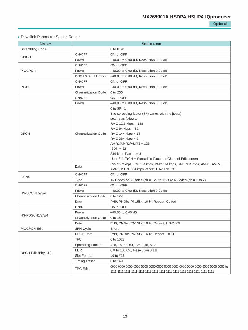
Display Setting rangeScrambling Code 0 to 8191
CPICH ON/OFF ON or OFFPower –40.00 to 0.00 dB, Resolution 0.01 dBON/OFF ON or OFF
P-CCPCH Power –40.00 to 0.00 dB, Resolution 0.01 dBP-SCH & S-SCH Power –40.00 to 0.00 dB, Resolution 0.01 dBON/OFF ON or OFF
PICH Power –40.00 to 0.00 dB, Resolution 0.01 dBChannelization Code 0 to 255ON/OFF ON or OFFPower –40.00 to 0.00 dB, Resolution 0.01 dB
0 to SF –1The spreading factor (SF) varies with the [Data] setting as follows:RMC 12.2 kbps = 128
Channelization Code RMC 64 kbps = 32RMC 144 kbps = 16RMC 384 kbps = 8AMR1/AMR2/AMR3 = 128ISDN = 32384 kbps Packet = 8
Data RMC12.2 kbps, RMC 64 kbps, RMC 144 kbps, RMC 384 kbps, AMR1, AMR2, AMR3, ISDN, 384 kbps Packet
OCNS ON/OFF ON or OFFType 16 Codes
P-CCPCH Edit SFN Cycle ShortTFCI 0 to 1023DPCH Edit (Phy CH)Timing Offset 0 to 149
DPCH Edit (TrCH Edit) Data PN9, PN9fix, PN15fix, 16 bit Repeat
• Downlink Parameter Setting Range
DPCH
Display Setting rangeScrambling Code 0 to 16777215
Power –40.00 to 0 dBUL-DPCCH, UL-DPDCH
DataRMC 12.2 kbps, RMC 64 kbps, RMC 144 kbps, RMC 384 kbps, AMR1, AMR2, AMR3, ISDN, 64 kbps Packet
DPCH Edit (Phy CH)TFCI 0 to 1023Timing Offset 0 to 149
DPCH Edit (TrCH Edit) Data PN9, PN9fix, PN15fix, 16 bit RepeatBeta c 0 to 15Channel GainBeta d 0 to 15
• Uplink Parameter Setting Range
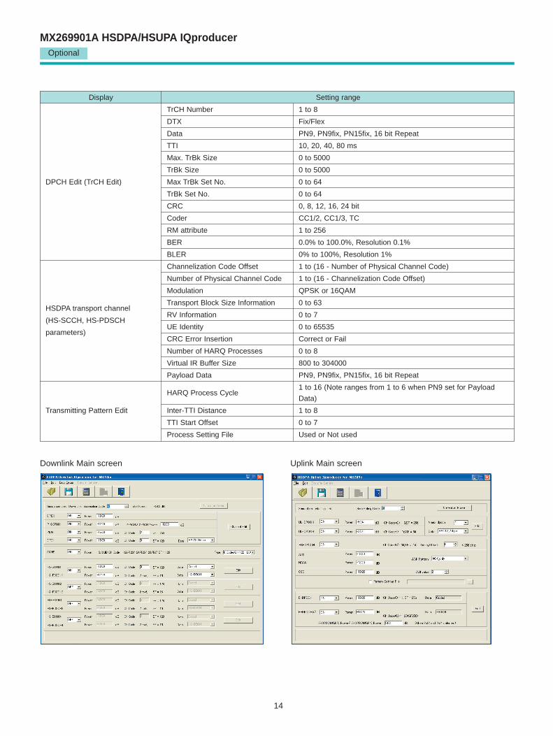
Downlink Main screen Uplink Main screen
12
MX269901A HSDPA/HSUPA IQproducerOptional
HSDPA/HSUPA IQproducer
This optional GUI-based PC application software is used to setparameters and generate waveform patterns for 3GPPHSDPA/HSUPA (Uplink/Downlink) systems.If complete control of all W-CDMA parameters is required, theMX269901A HSDPA/HSUPA IQproducer software (sold separately) can be used. For details, see the MX269901AHSDPA/HSUPA IQproducer section of this document.Once created, the waveform pattern file is downloaded to theMS269xA hard drive. Using the MS269xA-020, Vector SignalGenerator Option functionality, the files are loaded, selected,and output as a modulated RF signal.The HS-PDSCH and HS-DPCCH parameters specified inTS25.212 can be set. The Downlink Easy Setup functionassigns default values to some parameters and sets otheritems to typical values, making the creation of an accuratewaveform pattern fast and easy.
• Downlink SettingsVarious downlink parameters can be set. (For details, see theDownlink Parameter Setting table described later.)The Downlink Easy Setup function supports the HSDPA FixedReference Channel (FRC) items specified in 3GPP TS25.101,and the Reference Measurement Channel (RMC) items specified in 3GPP TS25.101 and TS25.104.
Easy Setup Items include:FRC: H-Set1 (QPSK)
H-Set1 (16QAM)H-Set2 (QPSK)H-Set2 (16QAM)H-Set3 (QPSK)H-Set3 (16QAM) H-Set4 H-Set5
RMC: RMC 12.2 kbps (RX test)RMC 12.2 kbps (Performance test)RMC 64 kbps (Performance test)RMC 144 kbps (Performance test)RMC 384 kbps (Performance test)
• Uplink SettingsUplink sets parameters for UL-DPCCH/UL-DPDCH and HS-DPCCH channels and generates waveform patterns.(For details, see the Uplink Parameter Setting Range tabledescribed later).
HS-DPCCH (ACK, NACK, CQI)UL-DPCCHUL-DPDCHE-DPCCHE-DPDCH (s)
• Parameter Save/RecallThe numeric values and settings for each item can be saved ina parameter file. Enter the file name in the [File name] field andclick the [Save] button to save the parameter file. A saved parameter file is recalled by selecting it in the file listand clicking the [Open] button.
CPU Pentium III, 1 GHz or faster
Memory ≥ 512 MB
HDD ≥ 5 GB
Display 1024 x 768 pixels min.
OS Windows 2000 Professional, Windows XP
• IQproducer Operating Environment
13
Optional
MX269901A HSDPA/HSUPA IQproducer
Display Setting range
Scrambling Code 0 to 8191
CPICH ON/OFF ON or OFF
Power –40.00 to 0.00 dB, Resolution 0.01 dB
ON/OFF ON or OFF
P-CCPCH Power –40.00 to 0.00 dB, Resolution 0.01 dB
P-SCH & S-SCH Power –40.00 to 0.00 dB, Resolution 0.01 dB
ON/OFF ON or OFF
PICH Power –40.00 to 0.00 dB, Resolution 0.01 dB
Channelization Code 0 to 255
ON/OFF ON or OFF
Power –40.00 to 0.00 dB, Resolution 0.01 dB
0 to SF –1
The spreading factor (SF) varies with the [Data]
setting as follows:
RMC 12.2 kbps = 128
RMC 64 kbps = 32
DPCH Channelization Code RMC 144 kbps = 16
RMC 384 kbps = 8
AMR1/AMR2/AMR3 = 128
ISDN = 32
384 kbps Packet = 8
User Edit TrCH = Spreading Factor of Channel Edit screen
Data RMC12.2 kbps, RMC 64 kbps, RMC 144 kbps, RMC 384 kbps, AMR1, AMR2,
AMR3, ISDN, 384 kbps Packet, User Edit TrCH
OCNS ON/OFF ON or OFF
Type 16 Codes or 6 Codes (ch = 122 to 127) or 6 Codes (ch = 2 to 7)
ON/OFF ON or OFF
HS-SCCH1/2/3/4 Power –40.00 to 0.00 dB, Resolution 0.01 dB
Channelization Code 0 to 127
Data PN9, PN9fix, PN15fix, 16 bit Repeat, Coded
ON/OFF ON or OFF
Power –40.00 to 0.00 dBHS-PDSCH1/2/3/4
Channelization Code 0 to 15
Data PN9, PN9fix, PN15fix, 16 bit Repeat, HS-DSCH
P-CCPCH Edit SFN Cycle Short
DPCH Data PN9, PN9fix, PN15fix, 16 bit Repeat, TrCH
TFCI 0 to 1023
Spreading Factor 4, 8, 16, 32, 64, 128, 256, 512
BER 0.0 to 100.0%, Resolution 0.1%DPCH Edit (Phy CH)
Slot Format #0 to #16
Timing Offset 0 to 149
TPC Edit0000 0000 0000 0000 0000 0000 0000 0000 0000 0000 0000 0000 0000 0000 0000 to
1111 1111 1111 1111 1111 1111 1111 1111 1111 1111 1111 1111 1111 1111 1111
• Downlink Parameter Setting Range
14
Optional
MX269901A HSDPA/HSUPA IQproducer
Display Setting range
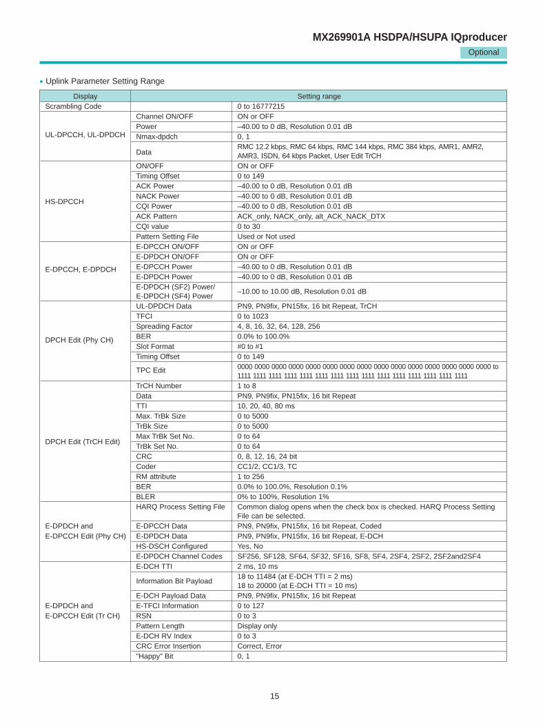
TrCH Number 1 to 8
DTX Fix/Flex
Data PN9, PN9fix, PN15fix, 16 bit Repeat
TTI 10, 20, 40, 80 ms
Max. TrBk Size 0 to 5000
TrBk Size 0 to 5000
DPCH Edit (TrCH Edit) Max TrBk Set No. 0 to 64
TrBk Set No. 0 to 64
CRC 0, 8, 12, 16, 24 bit
Coder CC1/2, CC1/3, TC
RM attribute 1 to 256
BER 0.0% to 100.0%, Resolution 0.1%
BLER 0% to 100%, Resolution 1%
Channelization Code Offset 1 to (16 - Number of Physical Channel Code)
Number of Physical Channel Code 1 to (16 - Channelization Code Offset)
Modulation QPSK or 16QAM
HSDPA transport channelTransport Block Size Information 0 to 63
(HS-SCCH, HS-PDSCHRV Information 0 to 7
UE Identity 0 to 65535parameters)
CRC Error Insertion Correct or Fail
Number of HARQ Processes 0 to 8
Virtual IR Buffer Size 800 to 304000
Payload Data PN9, PN9fix, PN15fix, 16 bit Repeat
HARQ Process Cycle 1 to 16 (Note ranges from 1 to 6 when PN9 set for Payload
Data)
Transmitting Pattern Edit Inter-TTI Distance 1 to 8
TTI Start Offset 0 to 7
Process Setting File Used or Not used
Downlink Main screen Uplink Main screen
15
Optional
MX269901A HSDPA/HSUPA IQproducer
Display Setting rangeScrambling Code 0 to 16777215
Channel ON/OFF ON or OFFPower –40.00 to 0 dB, Resolution 0.01 dB
UL-DPCCH, UL-DPDCH Nmax-dpdch 0, 1
Data RMC 12.2 kbps, RMC 64 kbps, RMC 144 kbps, RMC 384 kbps, AMR1, AMR2, AMR3, ISDN, 64 kbps Packet, User Edit TrCH
ON/OFF ON or OFFTiming Offset 0 to 149ACK Power –40.00 to 0 dB, Resolution 0.01 dB
HS-DPCCHNACK Power –40.00 to 0 dB, Resolution 0.01 dBCQI Power –40.00 to 0 dB, Resolution 0.01 dBACK Pattern ACK_only, NACK_only, alt_ACK_NACK_DTXCQI value 0 to 30Pattern Setting File Used or Not usedE-DPCCH ON/OFF ON or OFFE-DPDCH ON/OFF ON or OFF
E-DPCCH, E-DPDCH E-DPCCH Power –40.00 to 0 dB, Resolution 0.01 dBE-DPDCH Power –40.00 to 0 dB, Resolution 0.01 dBE-DPDCH (SF2) Power/E-DPDCH (SF4) Power
–10.00 to 10.00 dB, Resolution 0.01 dB
UL-DPDCH Data PN9, PN9fix, PN15fix, 16 bit Repeat, TrCHTFCI 0 to 1023Spreading Factor 4, 8, 16, 32, 64, 128, 256BER 0.0% to 100.0%DPCH Edit (Phy CH)Slot Format #0 to #1Timing Offset 0 to 149
TPC Edit 0000 0000 0000 0000 0000 0000 0000 0000 0000 0000 0000 0000 0000 0000 0000 to 1111 1111 1111 1111 1111 1111 1111 1111 1111 1111 1111 1111 1111 1111 1111
TrCH Number 1 to 8Data PN9, PN9fix, PN15fix, 16 bit RepeatTTI 10, 20, 40, 80 msMax. TrBk Size 0 to 5000TrBk Size 0 to 5000
DPCH Edit (TrCH Edit)Max TrBk Set No. 0 to 64TrBk Set No. 0 to 64CRC 0, 8, 12, 16, 24 bitCoder CC1/2, CC1/3, TCRM attribute 1 to 256BER 0.0% to 100.0%, Resolution 0.1%BLER 0% to 100%, Resolution 1%HARQ Process Setting File Common dialog opens when the check box is checked. HARQ Process Setting
File can be selected. E-DPDCH and E-DPCCH Data PN9, PN9fix, PN15fix, 16 bit Repeat, CodedE-DPCCH Edit (Phy CH) E-DPDCH Data PN9, PN9fix, PN15fix, 16 bit Repeat, E-DCH
HS-DSCH Configured Yes, NoE-DPDCH Channel Codes SF256, SF128, SF64, SF32, SF16, SF8, SF4, 2SF4, 2SF2, 2SF2and2SF4E-DCH TTI 2 ms, 10 ms
Information Bit Payload18 to 11484 (at E-DCH TTI = 2 ms)18 to 20000 (at E-DCH TTI = 10 ms)
E-DCH Payload Data PN9, PN9fix, PN15fix, 16 bit RepeatE-DPDCH and E-TFCI Information 0 to 127E-DPCCH Edit (Tr CH) RSN 0 to 3
Pattern Length Display onlyE-DCH RV Index 0 to 3CRC Error Insertion Correct, Error"Happy" Bit 0, 1
• Uplink Parameter Setting Range
16
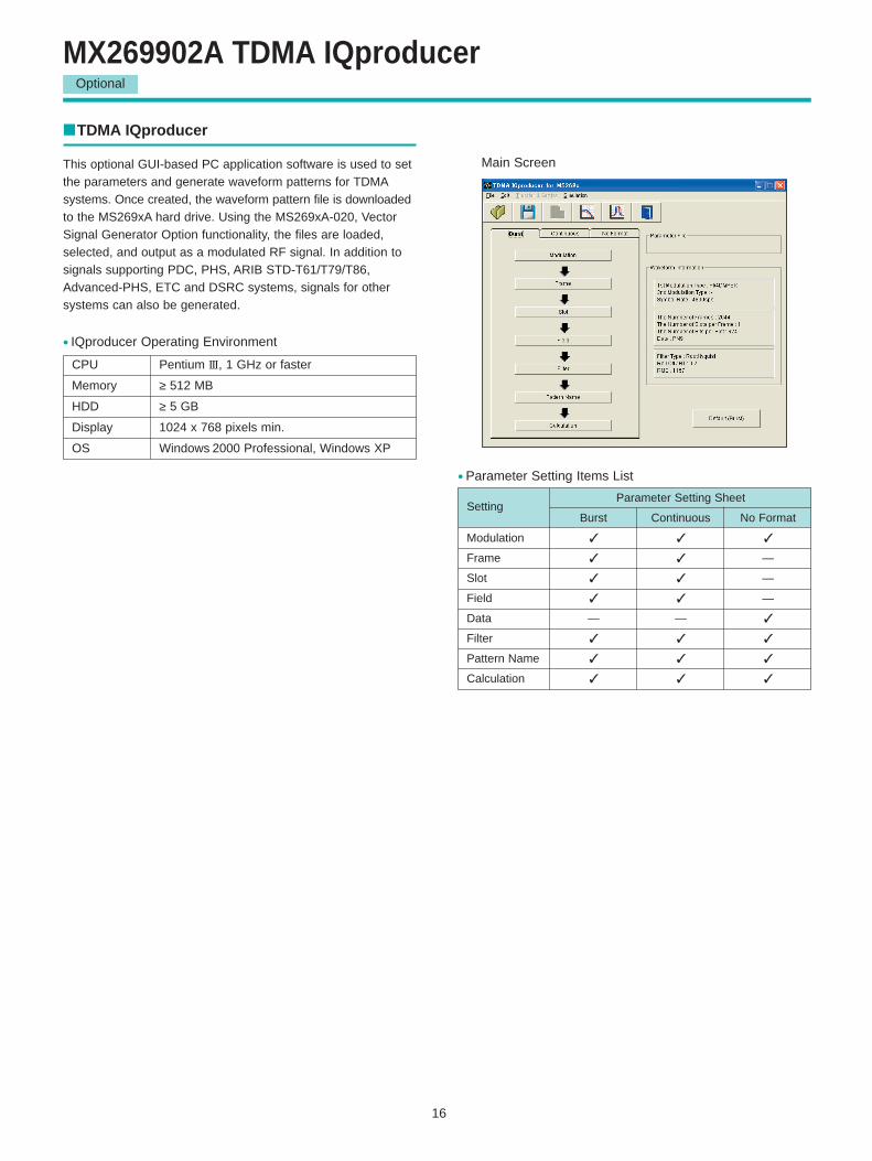
MX269902A TDMA IQproducerOptional
TDMA IQproducer
This optional GUI-based PC application software is used to setthe parameters and generate waveform patterns for TDMAsystems. Once created, the waveform pattern file is downloadedto the MS269xA hard drive. Using the MS269xA-020, VectorSignal Generator Option functionality, the files are loaded,selected, and output as a modulated RF signal. In addition tosignals supporting PDC, PHS, ARIB STD-T61/T79/T86,Advanced-PHS, ETC and DSRC systems, signals for othersystems can also be generated.
Main Screen
• Parameter Setting Items List
Setting Parameter Setting Sheet
Burst Continuous No Format
Modulation
Frame —
Slot —
Field —
Data — —
Filter
Pattern Name
Calculation
CPU Pentium III, 1 GHz or faster
Memory ≥ 512 MB
HDD ≥ 5 GB
Display 1024 x 768 pixels min.
OS Windows 2000 Professional, Windows XP
• IQproducer Operating Environment
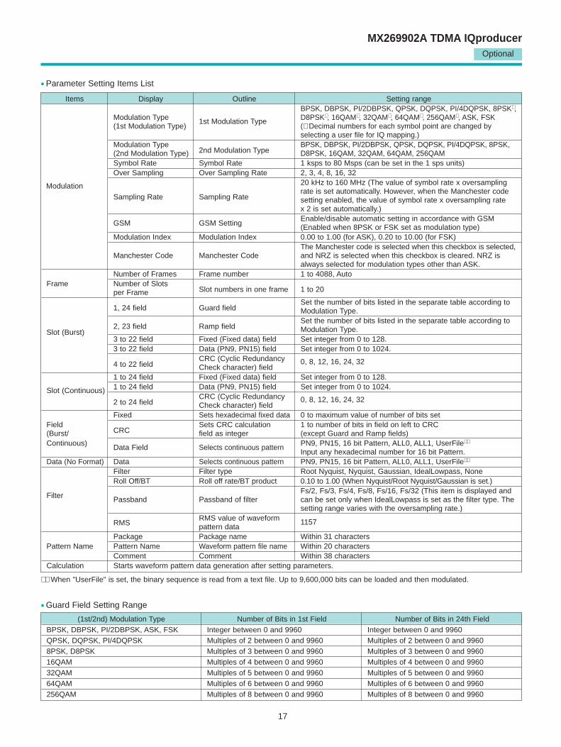
17
Optional
MX269902A TDMA IQproducer
(1st/2nd) Modulation Type Number of Bits in 1st Field Number of Bits in 24th FieldBPSK, DBPSK, PI/2DBPSK, ASK, FSK Integer between 0 and 9960 Integer between 0 and 9960QPSK, DQPSK, PI/4DQPSK Multiples of 2 between 0 and 9960 Multiples of 2 between 0 and 99608PSK, D8PSK Multiples of 3 between 0 and 9960 Multiples of 3 between 0 and 996016QAM Multiples of 4 between 0 and 9960 Multiples of 4 between 0 and 996032QAM Multiples of 5 between 0 and 9960 Multiples of 5 between 0 and 996064QAM Multiples of 6 between 0 and 9960 Multiples of 6 between 0 and 9960256QAM Multiples of 8 between 0 and 9960 Multiples of 8 between 0 and 9960
Items Display Outline Setting rangeBPSK, DBPSK, PI/2DBPSK, QPSK, DQPSK, PI/4DQPSK, 8PSK∗ ,
Modulation Type D8PSK∗ , 16QAM∗ , 32QAM∗ , 64QAM∗ , 256QAM∗ , ASK, FSK (1st Modulation Type)
1st Modulation Type(∗ Decimal numbers for each symbol point are changed by selecting a user file for IQ mapping.)
Modulation Type2nd Modulation Type
BPSK, DBPSK, PI/2DBPSK, QPSK, DQPSK, PI/4DQPSK, 8PSK, (2nd Modulation Type) D8PSK, 16QAM, 32QAM, 64QAM, 256QAMSymbol Rate Symbol Rate 1 ksps to 80 Msps (can be set in the 1 sps units)Over Sampling Over Sampling Rate 2, 3, 4, 8, 16, 32
20 kHz to 160 MHz (The value of symbol rate x oversampling
Sampling Rate Sampling Raterate is set automatically. However, when the Manchester codesetting enabled, the value of symbol rate x oversampling rate x 2 is set automatically.)Enable/disable automatic setting in accordance with GSM
GSM GSM Setting (Enabled when 8PSK or FSK set as modulation type) Modulation Index Modulation Index 0.00 to 1.00 (for ASK), 0.20 to 10.00 (for FSK)
The Manchester code is selected when this checkbox is selected, Manchester Code Manchester Code and NRZ is selected when this checkbox is cleared. NRZ is
always selected for modulation types other than ASK.Number of Frames Frame number 1 to 4088, Auto
Frame Number of Slots Slot numbers in one frame 1 to 20per Frame
1, 24 field Guard fieldSet the number of bits listed in the separate table according to Modulation Type.
2, 23 field Ramp fieldSet the number of bits listed in the separate table according to
Slot (Burst) Modulation Type.3 to 22 field Fixed (Fixed data) field Set integer from 0 to 128.3 to 22 field Data (PN9, PN15) field Set integer from 0 to 1024.
4 to 22 fieldCRC (Cyclic Redundancy Check character) field
0, 8, 12, 16, 24, 32
1 to 24 field Fixed (Fixed data) field Set integer from 0 to 128.
Slot (Continuous) 1 to 24 field Data (PN9, PN15) field Set integer from 0 to 1024.
2 to 24 fieldCRC (Cyclic Redundancy Check character) field
0, 8, 12, 16, 24, 32
Fixed Sets hexadecimal fixed data 0 to maximum value of number of bits setField
CRCSets CRC calculation 1 to number of bits in field on left to CRC
(Burst/ field as integer (except Guard and Ramp fields)Continuous) Data Field Selects continuous pattern PN9, PN15, 16 bit Pattern, ALL0, ALL1, UserFile∗∗
Input any hexadecimal number for 16 bit Pattern.Data (No Format) Data Selects continuous pattern PN9, PN15, 16 bit Pattern, ALL0, ALL1, UserFile∗∗
Filter Filter type Root Nyquist, Nyquist, Gaussian, IdealLowpass, NoneRoll Off/BT Roll off rate/BT product 0.10 to 1.00 (When Nyquist/Root Nyquist/Gaussian is set.)
FilterFs/2, Fs/3, Fs/4, Fs/8, Fs/16, Fs/32 (This item is displayed and
Passband Passband of filter can be set only when IdealLowpass is set as the filter type. The setting range varies with the oversampling rate.)
RMSRMS value of waveform pattern data
1157
Package Package name Within 31 charactersPattern Name Pattern Name Waveform pattern file name Within 20 characters
Comment Comment Within 38 charactersCalculation Starts waveform pattern data generation after setting parameters.
• Guard Field Setting Range
• Parameter Setting Items List
Modulation
∗∗ When "UserFile" is set, the binary sequence is read from a text file. Up to 9,600,000 bits can be loaded and then modulated.
18
Optional
MX269902A TDMA IQproducer
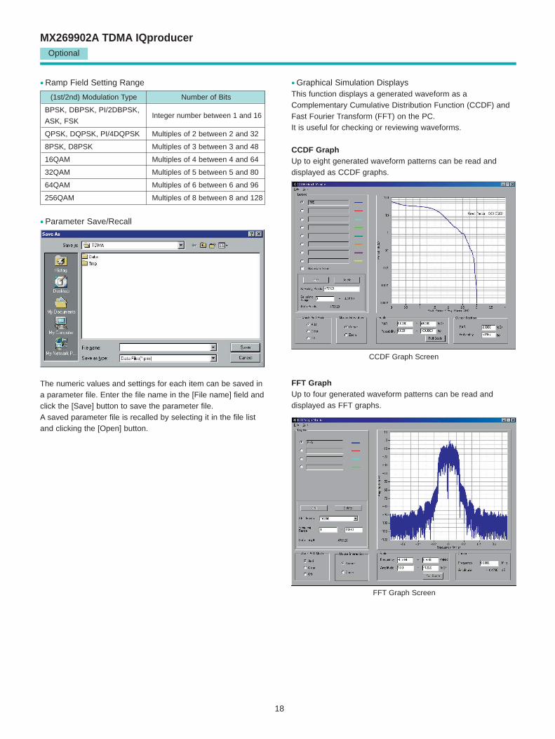
• Ramp Field Setting Range
(1st/2nd) Modulation Type Number of Bits
BPSK, DBPSK, PI/2DBPSK,
ASK, FSKInteger number between 1 and 16
QPSK, DQPSK, PI/4DQPSK Multiples of 2 between 2 and 32
8PSK, D8PSK Multiples of 3 between 3 and 48
16QAM Multiples of 4 between 4 and 64
32QAM Multiples of 5 between 5 and 80
64QAM Multiples of 6 between 6 and 96
256QAM Multiples of 8 between 8 and 128
• Parameter Save/Recall
• Graphical Simulation DisplaysThis function displays a generated waveform as aComplementary Cumulative Distribution Function (CCDF) andFast Fourier Transform (FFT) on the PC. It is useful for checking or reviewing waveforms.
CCDF GraphUp to eight generated waveform patterns can be read and displayed as CCDF graphs.
CCDF Graph Screen
FFT Graph Screen
FFT GraphUp to four generated waveform patterns can be read and displayed as FFT graphs.
The numeric values and settings for each item can be saved ina parameter file. Enter the file name in the [File name] field andclick the [Save] button to save the parameter file. A saved parameter file is recalled by selecting it in the file listand clicking the [Open] button.
19
MX269904A Multi-Carrier IQproducerOptional
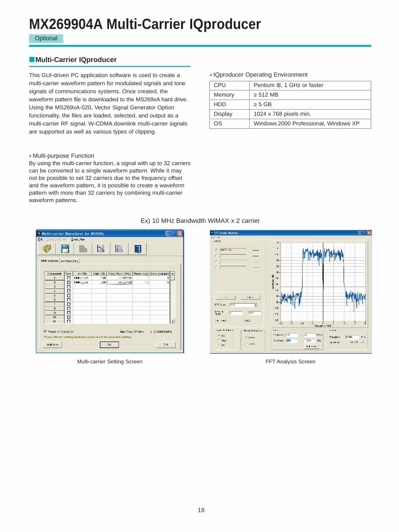
Multi-Carrier IQproducer
This GUI-driven PC application software is used to create amulti-carrier waveform pattern for modulated signals and tonesignals of communications systems. Once created, the waveform pattern file is downloaded to the MS269xA hard drive.Using the MS269xA-020, Vector Signal Generator Option functionality, the files are loaded, selected, and output as amulti-carrier RF signal. W-CDMA downlink multi-carrier signalsare supported as well as various types of clipping.
• Multi-purpose FunctionBy using the multi-carrier function, a signal with up to 32 carrierscan be converted to a single waveform pattern. While it maynot be possible to set 32 carriers due to the frequency offsetand the waveform pattern, it is possible to create a waveformpattern with more than 32 carriers by combining multi-carrierwaveform patterns.
Ex) 10 MHz Bandwidth WiMAX x 2 carrier
Multi-carrier Setting Screen FFT Analysis Screen
CPU Pentium III, 1 GHz or faster
Memory ≥ 512 MB
HDD ≥ 5 GB
Display 1024 x 768 pixels min.
OS Windows 2000 Professional, Windows XP
• IQproducer Operating Environment
20
Optional
MX269904A Multi-Carrier IQproducer
Multi-carrier Setting Screen Multi-carrier Setting Screen
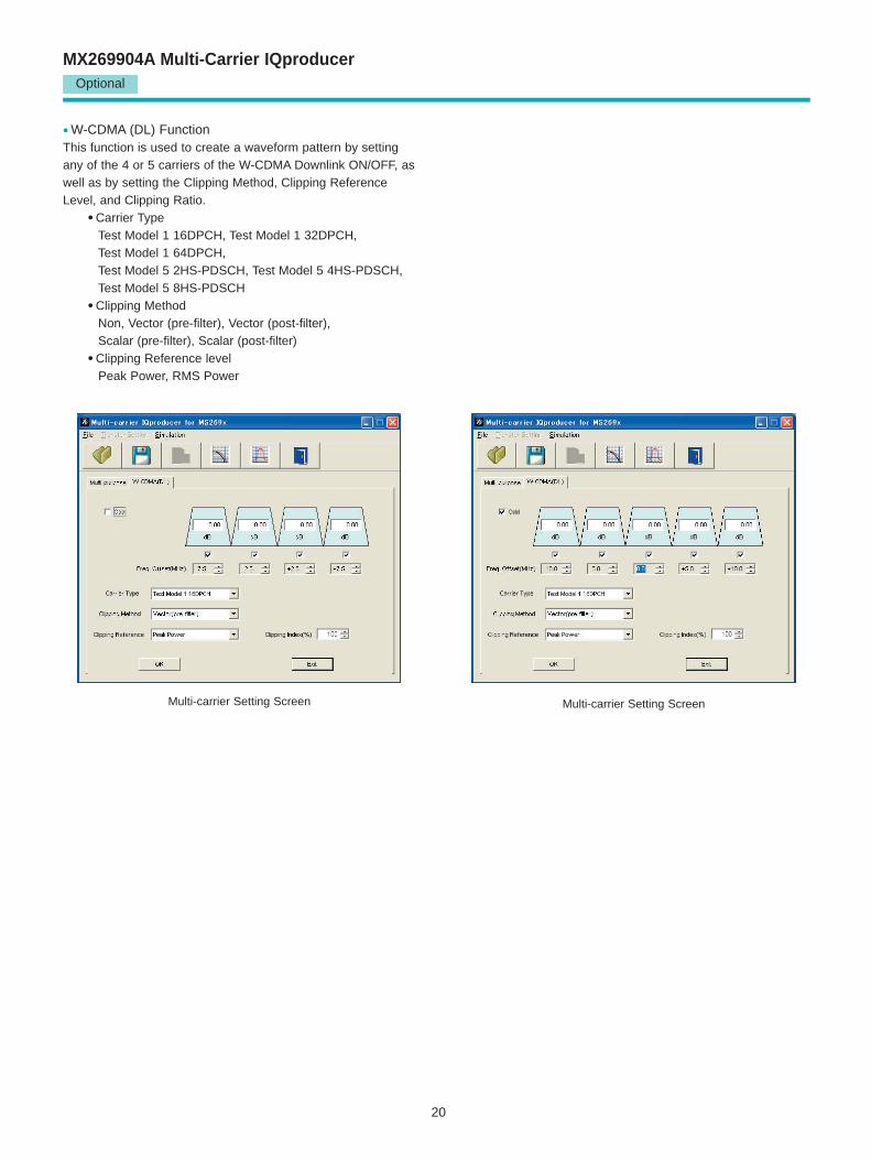
• W-CDMA (DL) FunctionThis function is used to create a waveform pattern by settingany of the 4 or 5 carriers of the W-CDMA Downlink ON/OFF, aswell as by setting the Clipping Method, Clipping ReferenceLevel, and Clipping Ratio.
• Carrier TypeTest Model 1 16DPCH, Test Model 1 32DPCH, Test Model 1 64DPCH, Test Model 5 2HS-PDSCH, Test Model 5 4HS-PDSCH,Test Model 5 8HS-PDSCH
• Clipping MethodNon, Vector (pre-filter), Vector (post-filter), Scalar (pre-filter), Scalar (post-filter)
• Clipping Reference levelPeak Power, RMS Power
21
MX269905A Mobile WiMAX IQproducerOptional
Mobile WiMAX IQproducer
This GUI-driven PC application software is used to set parameters and generate waveform patterns based on theIEEE 802.16e-2005 WirelessMAN-OFDMA standard. Signalsthat comply with this particular specification are also knows asmobile WiMAX signals. Once created, the waveform pattern fileis downloaded to the MS269xA hard drive. Using the MS269xA-020, Vector Signal Generator Option functionality,the files are loaded, selected, and output as a modulatedWiMAX signal. Permutation zones and user bursts are easy toconfigure in a frame using drop-and-drag functionality in auser-friendly GUI. Modulation, coding type, and coding rate canbe set for each user burst. Most receiver tests described inIEEE 802.16e-2005 (Section 8.4.13, Receiver Requirement)can be performed except those functional tests requiring equipment other than a Signal Generator.
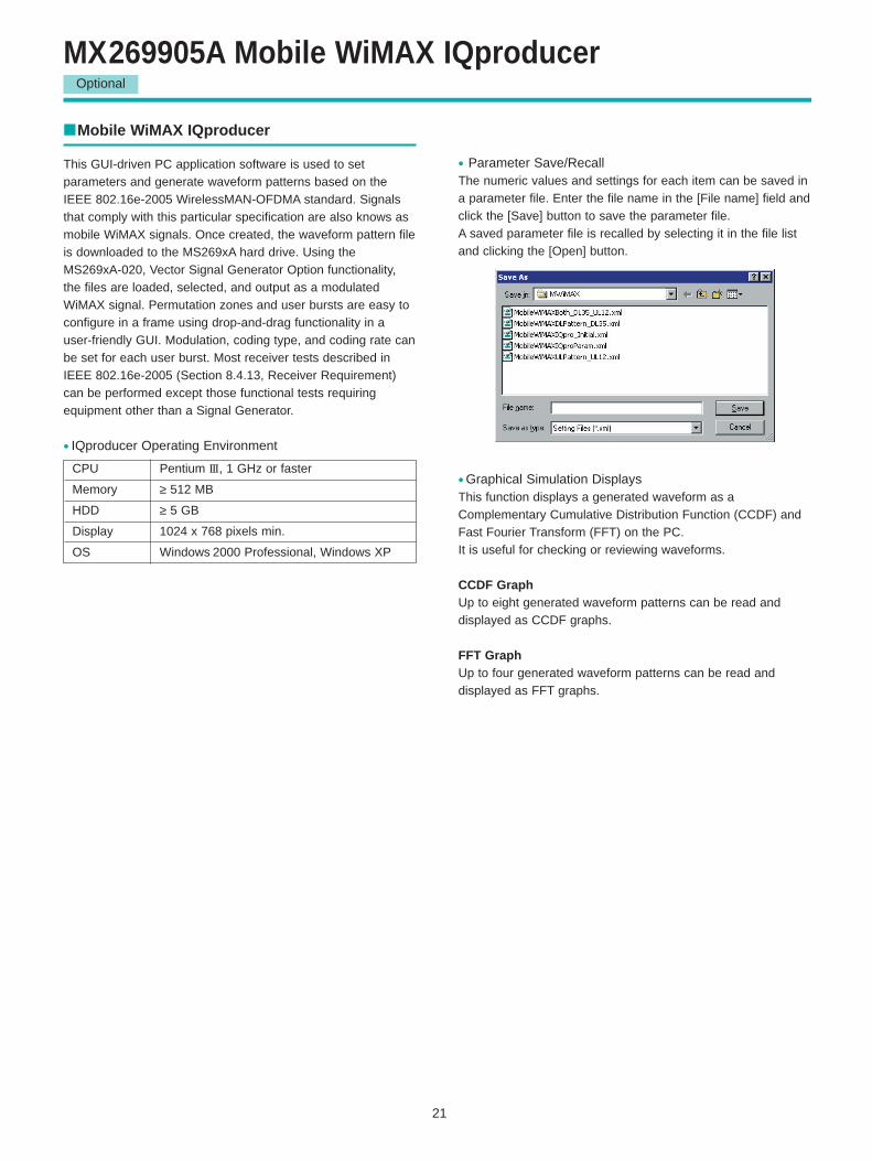
• Parameter Save/RecallThe numeric values and settings for each item can be saved ina parameter file. Enter the file name in the [File name] field andclick the [Save] button to save the parameter file. A saved parameter file is recalled by selecting it in the file listand clicking the [Open] button.
• Graphical Simulation DisplaysThis function displays a generated waveform as aComplementary Cumulative Distribution Function (CCDF) andFast Fourier Transform (FFT) on the PC. It is useful for checking or reviewing waveforms.
CCDF GraphUp to eight generated waveform patterns can be read and displayed as CCDF graphs.
FFT GraphUp to four generated waveform patterns can be read and displayed as FFT graphs.
CPU Pentium III, 1 GHz or faster
Memory ≥ 512 MB
HDD ≥ 5 GB
Display 1024 x 768 pixels min.
OS Windows 2000 Professional, Windows XP
• IQproducer Operating Environment
22
Optional
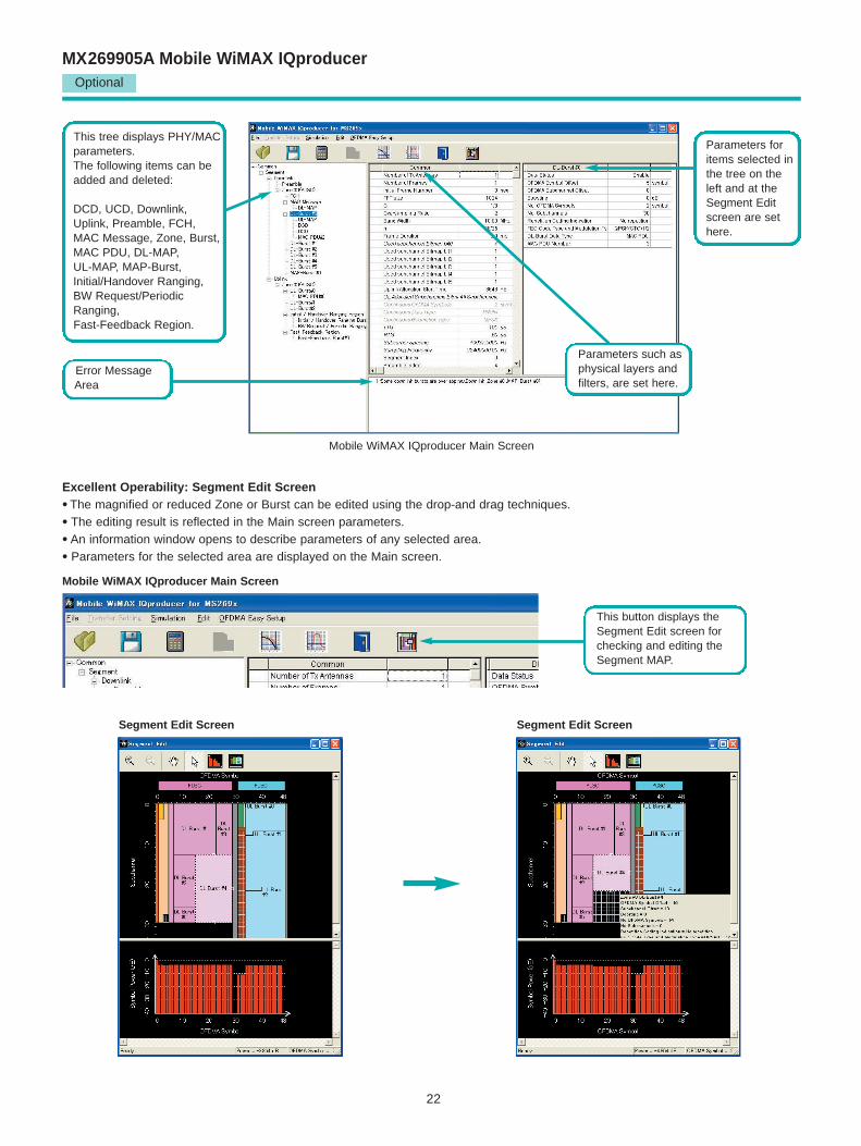
MX269905A Mobile WiMAX IQproducer
Mobile WiMAX IQproducer Main Screen
Mobile WiMAX IQproducer Main Screen
Segment Edit Screen Segment Edit Screen
Excellent Operability: Segment Edit Screen• The magnified or reduced Zone or Burst can be edited using the drop-and drag techniques.
• The editing result is reflected in the Main screen parameters.
• An information window opens to describe parameters of any selected area.
• Parameters for the selected area are displayed on the Main screen.
This tree displays PHY/MAC parameters.The following items can beadded and deleted:
DCD, UCD, Downlink,Uplink, Preamble, FCH,MAC Message, Zone, Burst,MAC PDU, DL-MAP, UL-MAP, MAP-Burst, Initial/Handover Ranging, BW Request/PeriodicRanging, Fast-Feedback Region.
Error MessageArea
Parameters such asphysical layers andfilters, are set here.
Parameters foritems selected inthe tree on theleft and at theSegment Editscreen are sethere.
This button displays theSegment Edit screen forchecking and editing theSegment MAP.
23
Optional
MX269905A Mobile WiMAX IQproducer
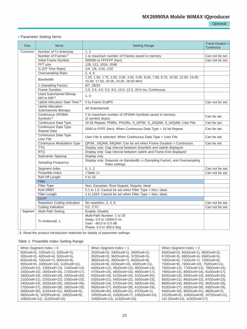
Tree Items Setting RangeFrame Duration =Continuous
Common Number of Tx Antennas 1, 2Number of Frames∗ 1 1 to maximum number of Frames saved in memory Can not be set.Initial Frame Number 000000 to FFFFFF (hex) Can not be set.FFT size 128, 512, 1024, 2048G (CP Time Ratio) 1/4, 1/8, 1/16, 1/32Oversampling Ratio 2, 4, 8
Bandwidth1.25, 1.50, 1.75, 2.50, 3.00, 3.50, 5.00, 6.00, 7.00, 8.75, 10.00, 12.00, 14.00, 15.00, 17.50, 20.00, 24.00, 28.00 MHz
n (Sampling Factor) 8/7, 28/25Frame Duration 2.0, 2.5, 4.0, 5.0, 8.0, 10.0, 12.5, 20.0 ms, ContinuousUsed Subchannel Bitmap bit0 to bit5∗ 1 1, 0
Uplink Allocation Start Time∗ 1 0 to Frame EndPS Can not be set.Uplink Allocation Subchannels Bitmaps
All Subchannels
Continuous OFDMA 2 to maximum number of OFDMA Symbols saved in memory Symbols∗ 1 (2-symbol steps)
Can be set.
Continuous Data Type 16 bit Repeat, PN9fix, PN15fix, S_QPSK, S_16QAM, S_64QAM, User File Can be set.Continuous Data Type Repeat Data
0000 to FFFF (hex): When Continuous Data Type = 16 bit Repeat Can be set.
Continuous Data Type User File
User File is selected: When Continuous Data Type = User File Can be set.
Continuous Modulation Type QPSK, 16QAM, 64QAM: Can be set when Frame Duration = Continuous Can be set.TTG Display only: Gap interval between Downlink and Uplink displayedRTG Display only: Gap interval between Uplink and Frame End displayedSubcarrier Spacing Display only
Sampling FrequencyDisplay only: Depends on Bandwidth, n (Sampling Factor), and Oversampling
Ratio settingsSegment Index 0, 1, 2 Can not be set.Preamble Index <Table 1> Can not be set.Roll Off Length 0 to 32FilterFilter Type Non, Gaussian, Root Nyquist, Nyquist, IdealRoll-Off/BT 0.1 to 1.0: Cannot be set when Filter Type = Non, Ideal.Filter Length 1 to 1024: Cannot be set when Filter Type = Non, Ideal. DLFPRepetition Coding Indication No repetition, 2, 4, 6 Can not be set.Coding Indication CC, CTC Can not be set.
Segment Multi-Path Setting Enable, DisableMulti-Path Number: 1 to 20
Tx Antenna0, 1 Delay: 0.0 to 10000.0 nsGain: –80.0 to 0.0 dBPhase: 0.0 to 359.9 deg
When Segment Index = 0 When Segment Index = 1 When Segment Index = 20(IDcell=0), 1(IDcell=1), 2(IDcell=2), 32(IDcell=0), 33(IDcell=1), 34(IDcell=2), 64(IDcell=0), 65(IDcell=1), 66(IDcell=2), 3(IDcell=3), 4(IDcell=4), 5(IDcell=5), 35(IDcell=3), 36(IDcell=4), 37(IDcell=5), 67(IDcell=3), 68(IDcell=4), 69(IDcell=5), 6(IDcell=6), 7(IDcell=7), 8(IDcell=8), 38(IDcell=6), 39(IDcell=7), 40(IDcell=8), 70(IDcell=6), 71(IDcell=7), 72(IDcell=8), 9(IDcell=9), 10(IDcell=10), 11(IDcell=11), 41(IDcell=9), 42(Idcell=10), 43(IDcell=11), 73(IDcell=9), 74(IDcell=10), 75(IDcell=11), 12(IDcell=12), 13(IDcell=13), 14(IDcell=14), 44(IDcell=12), 45(IDcell=13), 46(IDcell=14), 76(IDcell=12), 77(IDcell=13), 78(IDcell=14), 15(IDcell=15), 16(IDcell=16), 17(IDcell=17), 47(IDcell=15), 48(IDcell=16), 49(IDcell=17), 79(IDcell=15), 80(IDcell=16), 81(IDcell=17), 18(IDcell=18), 19(IDcell=19), 20(IDcell=20), 50(IDcell=18), 51(IDcell=19), 52(IDcell=20), 82(IDcell=18), 83(IDcell=19), 84(IDcell=20), 21(IDcell=21), 22(IDcell=22), 23(IDcell=23), 53(IDcell=21), 54(IDcell=22), 55(IDcell=23), 85(IDcell=21), 86(IDcell=22), 87(IDcell=23), 24(IDcell=24), 25(IDcell=25), 26(IDcell=26), 56(IDcell=24), 57(IDcell=25), 58(IDcell=26), 88(IDcell=24), 89(IDcell=25), 90(IDcell=26), 27(IDcell=27), 28(IDcell=28), 29(IDcell=29), 59(IDcell=27), 60(IDcell=28), 61(IDcell=29), 91(IDcell=27), 92(IDcell=28), 93(IDcell=29), 30(IDcell=30), 31(IDcell=31), 96(IDcell=0), 62(IDcell=30), 63(IDcell=31), 97(IDcell=1), 94(IDcell=30), 95(IDcell=31), 98(IDcell=2), 99(IDcell=3), 102(IDcell=6), 105(IDcell=9), 100(IDcell=4), 103(IDcell=7), 106(IDcell=10), 101(IDcell=5), 104(IDcell=8), 107(IDcell=11), 108(IDcell=12), 111(IDcell=15) 109(IDcell=13), 112(IDcell=16) 110 (IDcell=14), 113(IDcell=17)
• Parameter Setting Items
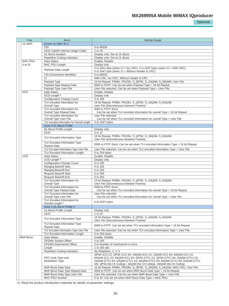
∗ 1: Read the product introduction materials for details of parameter settings.
Table 1: Preamble Index Setting Range
24
Optional
MX269905A Mobile WiMAX IQproducer
Tree Items Setting RangeDownlink Data Status Enable, DisablePreamble Data Status Enable, Disable
Preamble Index Display only: Set at Common.IDcell Display only: Depends on Preamble Index settings
Zone 0 to 7 Data Status Enable, DisablePermutation PUSC, PUSC (all SC), FUSC, AMC (6 x 1), AMC (3 x 2), AMC (2 x 3), AMC (1 x 6)STC/MIMO No transmit diversity, 2 Antenna MatrixA (STTD), 2 Antenna MatrixB vertical encoding
OFDMA Symbol Offset <Zone#0> 0 (Without Preamble), 1 (With Preamble)<Zone#1 to 7> 0 to 255 symbol (Without Preamble), 1 to 255 symbol (With Preamble)1 to 255 symbol [when FUSC and AMC (6 x 1)], 2 to 254 symbol [when PUSC, PUSC (all SC) and No. OFDMA Symbols AMC (3 x 2)], 3 to 255 symbol [when AMC (2 x 3)], 6 to 252 symbol [when AMC (1 x 6)]
DL-PermBase 0 to 31 (Cannot be set at Zone#0)DL-Burst Number 1 to 16PRBS_ID 0 to 3 (Cannot be set at Zone#0)
FCH Data Status Enable, DisableFCH Type 16 bit Repeat, PN9fix, PN15fix, DLFP, User FileFCH Type Repeat Data 0000 to FFFF (hex): Can be set when FCH Type = 16 bit RepeatFCH Type User File User File selected: Can be set when FCH Type = User FileUsed Subchannel Bitmap bit0 to 5 Display only: Set at Common.Repetition Coding Indication Display only: Set at Common.Coding Indication Display only: Set at Common.DL-MAP Length Display only: Set at DL-MAP.
MAC Message Data Status Enable, DisableDL-MAP Data Status Enable, Disable
DL-MAP Type∗ 1 16 bit Repeat, PN9fix, PN15fix, S_QPSK, S_16QAM, S_64QAM, DL-MAP, Compressed DL-MAP, User FileDL-MAP Type Repeat Data 0000 to FFFF (hex): Can be set when DL-MAP Type = 16 bit RepeatDL-MAP Type User File User File selected: Can be set when DL-MAP Type = User FileDL-MAP Length∗ 1 0 to 255 slotDCD Count 0 to 255: Can be set when DL-MAP Type = DL-MAP or Compressed DL-MAP
Base Station ID 0000 0000 0000 to FFFF FFFF FFFF (hex): Can be set when DL-MAP Type = DL-MAP or Compressed DL-MAP
DL-MAP PHY Synchronization FieldFrame Duration Display only: Set at Common.Initial Frame Number Display only: Set at Common.Zone # DL-MAP IE #DIUC (Downlink Interval Usage Code) 0 to 12OFDMA Symbol Offset Display only: Set at DL-Burst.OFDMA Subchannel Offset Display only: Set at DL-Burst.Boosting Display only: Set at DL-Burst. No. OFDMA Symbol Display only: Set at DL-Burst. No. Subchannels Display only: Set at DL-Burst. Repetition Coding Indication Display only: Set at DL-Burst.Zone # STC/Zone switch IEOFDMA Symbol Offset Display only: Set at DL-Zone.Permutation Display only: Set at DL-Zone.DL Use All SC Indicator Display onlyDL-PermBase Display only: Set at DL-Zone.
DL-Burst 0 to 15 Data Status Enable, DisableOFDMA Symbol Offset∗ 1 0 to 255OFDMA Subchannel Offset 0 to 63 [without AMC (2 x 3) and AMC (1 x 6)], 0 to 255 [when AMC (2 x 3) and AMC (1 x 6)]Boosting –12, –9, –6, –3, 0, +3, +6, +9 dBNo. OFDMA Symbols 1 to 127 symbolNo. Subchannels 1 to 63Repetition Coding Indication∗ 1 No repetition, 2, 4, 6
QPSK (CC) 1/2, QPSK (CC) 3/4, 16QAM (CC) 1/2, 16QAM (CC) 3/4, 64QAM (CC) 1/2, 64QAM (CC) FEC Code Type and 2/3, 64QAM (CC) 3/4, QPSK (CTC) 1/2, QPSK (CTC) 3/4, 16QAM (CTC) 1/2, 16QAM (CTC) 3/4, Modulation Type 64QAM (CTC) 1/2, 64QAM (CTC) 2/3, 64QAM (CTC) 3/4, 64QAM (CTC) 5/6, QPSK (No Ch Coding),
16QAM (No Ch Coding) , 64QAM (No Ch Coding) DL-Burst Data Type 16 bit Repeat, PN9fix, PN15fix, S_QPSK, S_16QAM, S_64QAM, MAC PDU, User FileDL-Burst Data Type Repeat Data 0000 to FFFF (hex): Can be set when DL-Burst Data Type = 16 bit RepeatDL-Burst Data Type User File User File selected: Can be set when DL-Burst Data Type = User FileMAC PDU Number 0 to 32
UL-MAP Data Status Enable, DisableUL-MAP Type 16 bit Repeat, PN9fix, PN15fix, S_QPSK, S_16QAM, S_64QAM, UL-MAP, Compressed UL-MAP, User FileUL-MAP Type Repeat Data 0000 to FFFF (hex): Can be set when UL-MAP Type = 16 bit Repeat.UL-MAP Type User File User File selected: Can be set when UL-MAP Type = User File.UL-MAP Length∗ 1 0 to 2037 bytesUCD Count 0 to 255: Can be set when UL-MAP Type = UL-MAP or Compressed UL-MAPUplink Allocation Start Time Display only: Set at Common.
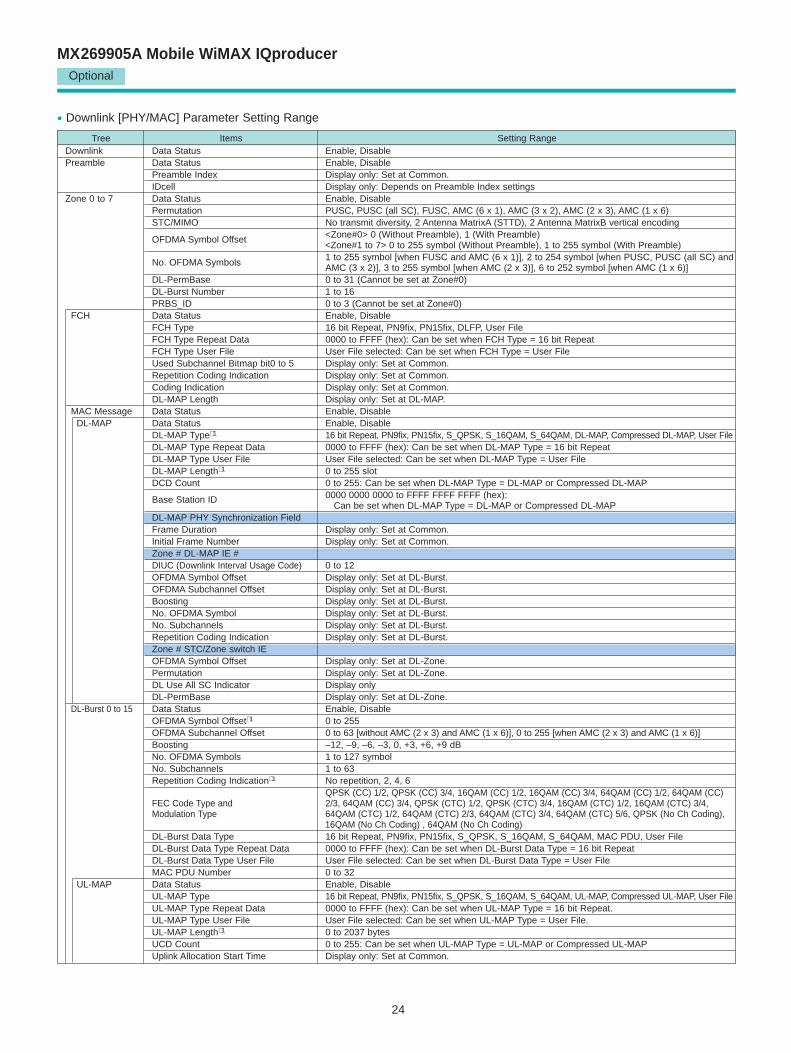
• Downlink [PHY/MAC] Parameter Setting Range
25
Optional
MX269905A Mobile WiMAX IQproducer
∗ 1: Read the product introduction materials for details of parameter settings.
Tree Items Setting RangeUL-MAP Zone# UL-MAP IE #
CID 0 to 65535UIUC (Uplink Interval Usage Code) 1 to 10UL-Burst Duration Display only: Set at UL-Burst.Repetition Coding Indication Display only: Set at UL-Burst.
MAC PDU Data Status Enable, Disable0 to 31 MAC PDU Length Display only
0 to 2041 byte (when CI = No CRC), 0 to 2037 bytes (when CI = With CRC), Payload Data Length 0 to 2047 byte (when CI = Without Header & CRC)CID (Connection Identifier) 0 to 65535CI With CRC, No CRC, Without Header & CRCPayload Type 16 bit Repeat, PN9fix, PN15fix, S_QPSK, S_16QAM, S_64QAM, User FilePayload Type Repeat Data 0000 to FFFF: Can be set when Payload Type = 16 bit Repeat.Payload Type User File User File selected: Can be set when Payload Type = User File.
DCD Data Status Enable, DisableDCD Length∗ 1 Display only Configuration Change Count 0 to 255TLV encoded information for 16 bit Repeat, PN9fix, PN15fix, S_QPSK, S_16QAM, S_64QAM, Overall Type User File (Discontinuous between Frames)TLV encoded information for 0000 to FFFF (hex): Overall Type Repeat Data Can be set when TLV encoded information for overall Type = 16 bit RepeatTLV encoded information for User File selected: Overall Type User File Can be set when TLV encoded information for overall Type = User FileTLV encoded information for Overall Length 0 to 2037 bytesZone # DL-Burst Profile DL-Burst Profile Length Display only DIUC 0 to 12
TLV Encoded Information Type 16 bit Repeat, PN9fix, PN15fix, S_QPSK, S_16QAM, S_64QAM, User File (Discontinuous between Frames)
TLV Encoded Information Type Repeat Data 0000 to FFFF (hex): Can be set when TLV encoded information Type = 16 bit Repeat
TLV Encoded Information Type User File User File selected: Can be set when TLV encoded information Type = User FileTLV Encoded Information Length 0 to 254 bytes
UCD Data Status Enable, DisableUCD Length∗ 1 Display only Configuration Change Count 0 to 255Ranging Backoff Start 0 to 255Ranging Backoff End 0 to 255Request Backoff Start 0 to 255Request Backoff End 0 to 255TLV Encoded Information for 16 bit Repeat, PN9fix, PN15fix, S_QPSK, S_16QAM, S_64QAM, Overall Type User File (Discontinuous between Frames)TLV Encoded Information for 0000 to FFFF (hex): Overall Type Repeat Data Can be set when TLV encoded information for overall Type = 16 bit RepeatTLV Encoded Information for User File selected: Overall Type User File Can be set when TLV encoded information for overall Type = User FileTLV Encoded Information for Overall Length∗ 1 0 to 2037 bytes
Zone # UL-Burst Profile #UL-Burst Profile Length Display only UIUC 1 to 10
TLV Encoded Information Type 16 bit Repeat, PN9fix, PN15fix, S_QPSK, S_16QAM, S_64QAM, User File (Discontinuous between Frames)
TLV Encoded Information Type Repeat Data 0000 to FFFF: Can be set when TLV encoded information Type = 16 bit Repeat
TLV Encoded Information Type User File User File selected: Can be set when TLV encoded information Type = User FileTLV Encoded Information Length 0 to 254 bytes
MAP-Burst Data Status Enable, DisableOFDMA Symbol Offset 0 to 255OFDMA Subchannel Offset 0 to Number of Subchannel in ZoneLength 1 to 255 slotRepetition Coding Indication No Repetition, 2, 4, 6
QPSK (CC) 1/2, QPSK (CC) 3/4, 16QAM (CC) 1/2, 16QAM (CC) 3/4, 64QAM (CC) 1/2, FEC Code Type and 64QAM (CC) 2/3, 64QAM (CC) 3/4, QPSK (CTC) 1/2, QPSK (CTC) 3/4, 16QAM (CTC) 1/2, Modulation Type 16QAM (CTC) 3/4, 64QAM (CTC) 1/2, 64QAM (CTC) 2/3, 64QAM (CTC) 3/4, 64QAM (CTC)
5/6, QPSK (No Ch Coding) , 16QAM (No Ch Coding) , 64QAM (No Ch Coding)MAP-Burst Data Type 16 bit Repeat, PN9fix, PN15fix, S_QPSK, S_16QAM, S_64QAM, MAC PDU, User FileMAP-Burst Data Type Repeat Data 0000 to FFFF: Can be set when MAP-Burst Data Type = 16 bit Repeat.MAP-Burst Data Type User File User File selected: Can be set when MAP-Burst Data Type = User File.MAC PDU Number 0 to 32: Can be set when MAP-Burst Data Type = MAC PDU.
Optional
MX269905A Mobile WiMAX IQproducer
26
Tree Items Setting RangeUplink Data Status Enable, DisableZone 0 to 7 Data Status Enable, Disable
Permutation PUSC, PUSC (w/o SC rotation), AMC (6 x 1), AMC (3 x 2), AMC (2 x 3), AMC (1 x 6)STC/MIMO Display onlyOFDMA Symbol Offset 0 to 255 symbol (at Zone#0: 0)No. OFDMA Symbols 1 to 255 symbolUL-PermBase 0 to 69UL-Burst Number 1 to 16
UL-Burst 0 to 15 Data Status Enable, DisableODFMA Symbol Offset Zone OFDMA Symbol Offset to “Zone OFDMA Symbol Offset + Zone No. OFDMA Symbol”OFDMA Subchannel Offset 0 to Zone Subchannel-1
UL Burst Duration 1 to 1023 [when AMC (6 x 1)], 2 to 2046 [when AMC (3 x 2)], 3 to 3069 [when PUSC, PUSC (w/o SC rotation) and AMC (2 x 3)], 6 to 6138 [when AMC (1 x 6)]
Burst Power Offset –10.00 to 10.00 dBRepetition Coding Indication∗ 1 No repetition, 2, 4, 6
QPSK (CC) 1/2, QPSK (CC) 3/4, 16QAM (CC) 1/2, 16QAM (CC) 3/4, 64QAM (CC) 1/2, FEC Code Type and 64QAM (CC) 2/3, 64QAM (CC) 3/4, QPSK (CTC) 1/2, QPSK (CTC) 3/4, 16QAM (CTC) 1/2, Modulation Type 16QAM (CTC) 3/4, 64QAM (CTC) 1/2, 64QAM (CTC) 2/3, 64QAM (CTC) 3/4, 64QAM (CTC) 5/6,
QPSK (No Ch Coding) , 16QAM (No Ch Coding) , 64QAM (No Ch Coding) UL-Burst Data Type 16 bit Repeat, PN9fix, PN15fix, S_QPSK, S_16QAM, S_64QAM, MAC PDU, User FileUL-Burst Data Type Repeat Data 0000 to FFFF: Can be set when UL-Burst Data Type = 16 bit RepeatUL-Burst Data Type User File User File selected: Can be set when UL-Burst Data Type = User FileMAC PDU Number 0 to 32: Can be set when UL-Burst Data Type = MAC PDU
MAC PDU 0 to 31 <Refer to MAC PDU of Downlink. >Initial/Handover Data Status Enable, DisableRanging Region OFDMA Symbol Offset “OFDMA Symbol Offset at Zone” to 255 symbol
OFDMA Subchannel Offset 0 to 126 [when PUSC and PUSC (w/o SC rotation).], 0 to 120 [without PUSC and PUSC (w/o SC rotation)]
No. OFDMA Symbols 1 to 127 [when AMC (6 x 1)], 2 to 126 [when AMC (3 x 2)], 3 to 126 [when PUSC, PUSC (w/o SC rotation) and AMC (2 x 3)], 6 to 126 [when AMC (1 x 6)]
No. Subchannels 6 to 126 [when PUSC and PUSC (w/o SC rotation)], 8 to 120 [without PUSC and PUSC (w/o SC rotation)]Initial/Handover Ranging Symbols 2, 4Initial/Handover Ranging Burst Number 1 to 16Ranging Region Combination Non, CombineBW Request/Periodic Ranging Offset 0 to “No.OFDMA Symbols at Initial/Handover Ranging Region”BW Request/Periodic Ranging Symbols 1, 3BW Request/Periodic Ranging Burst Number 0 to 16
Initial/Handover Data Status Enable, DisableRanging Burst OFDMA Symbol Offset 0 to 254
OFDMA Subchannel Offset 0 to 126 [when PUSC and PUSC (w/o SC rotation)], 0 to 120 [without PUSC and PUSC (w/o SC rotation)]No. OFDMA Symbols Display only No. Subchannels Display only Ranging Power Offset –10.00 to 10.00 dBRanging Code Number 0 to 255
BW Request/ Data Status Enable, Disable Periodic OFDMA Symbol Offset “OFDMA Symbol Offset at Zone” to 255 symbolRanging Region OFDMA Subchannel Offset 0 to 126 [when PUSC and PUSC (w/o SC rotation)], 0 to 120 [without PUSC and PUSC (w/o SC rotation)]
No. OFDMA Symbols 1 to 127 [when AMC (6 x 1)], 2 to 126 [when AMC (3 x 2)], 3 to 126 [when PUSC, PUSC (w/o SC rotation) and AMC (2 x 3)], 6 to 126 [when AMC (1 x 6)]
No. Subchannels 6 to 126 [when PUSC and PUSC (w/o SC rotation)], 8 to 120 [without PUSC and PUSC (w/o SC rotation)]BW Request/Periodic Ranging Symbols 1, 3BW Request/Periodic Ranging Burst Number 1 to 16
BW Request/ Data Status Enable, DisablePeriodic OFDMA Symbol Offset 0 to 255Ranging Burst OFDMA Subchannel Offset 0 to 126 [when PUSC and PUSC (w/o SC rotation)], 0 to 120 [without PUSC and PUSC (w/o SC rotation)]
No. OFDMA Symbols Display only No. Subchannels Display only Ranging Power Offset –10.00 to 10.00 dBRanging Code Number 0 to 255
Fast-Feedback Data Status Enable, DisableRegion OFDMA Symbol Offset “OFDMA Symbol Offset at Zone” to 255 symbol
OFDMA Subchannel Offset 0 to 127No. OFDMA Symbols 3 to 126No. Subchannels 1 to 127Fast-Feedback Type Display only Fast-Feedback Burst Number 1 to 32
Fast-Feedback Data Status Enable, DisableBurst OFDMA Symbol Offset 0 to 255
OFDMA Subchannel Offset 0 to 127No. OFDMA Symbols Display only No. Subchannels Display only Ranging Power Offset –10.00 to 10.00 dBPayload 000000 to 111111
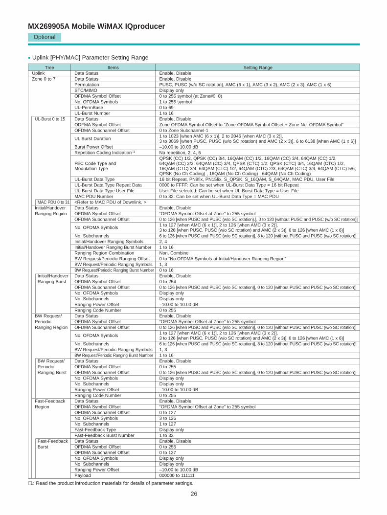
• Uplink [PHY/MAC] Parameter Setting Range
∗ 1: Read the product introduction materials for details of parameter settings.
27
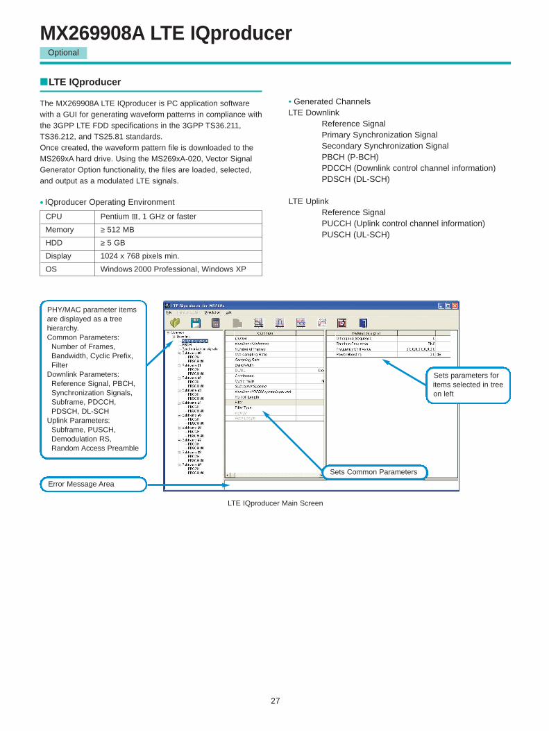
MX269908A LTE IQproducer
LTE IQproducer
The MX269908A LTE IQproducer is PC application softwarewith a GUI for generating waveform patterns in compliance withthe 3GPP LTE FDD specifications in the 3GPP TS36.211,TS36.212, and TS25.81 standards. Once created, the waveform pattern file is downloaded to theMS269xA hard drive. Using the MS269xA-020, Vector SignalGenerator Option functionality, the files are loaded, selected,and output as a modulated LTE signals.
• Generated ChannelsLTE Downlink
Reference SignalPrimary Synchronization SignalSecondary Synchronization SignalPBCH (P-BCH)PDCCH (Downlink control channel information)PDSCH (DL-SCH)
LTE UplinkReference SignalPUCCH (Uplink control channel information)PUSCH (UL-SCH)
LTE IQproducer Main Screen
PHY/MAC parameter itemsare displayed as a tree hierarchy.Common Parameters:
Number of Frames,Bandwidth, Cyclic Prefix,Filter
Downlink Parameters:Reference Signal, PBCH,Synchronization Signals,Subframe, PDCCH,PDSCH, DL-SCH
Uplink Parameters:Subframe, PUSCH,Demodulation RS,Random Access Preamble
Error Message Area
Sets Common Parameters
Sets parameters foritems selected in treeon left
Optional
CPU Pentium III, 1 GHz or faster
Memory ≥ 512 MB
HDD ≥ 5 GB
Display 1024 x 768 pixels min.
OS Windows 2000 Professional, Windows XP
• IQproducer Operating Environment
28
Optional
• Parameter Save/RecallThe numeric values and settings for each item can be saved ina parameter file. Enter the file name in the [File name] field andclick the [Save] button to save the parameter file. A saved parameter file is recalled by selecting it in the file listand clicking the [Open] button.
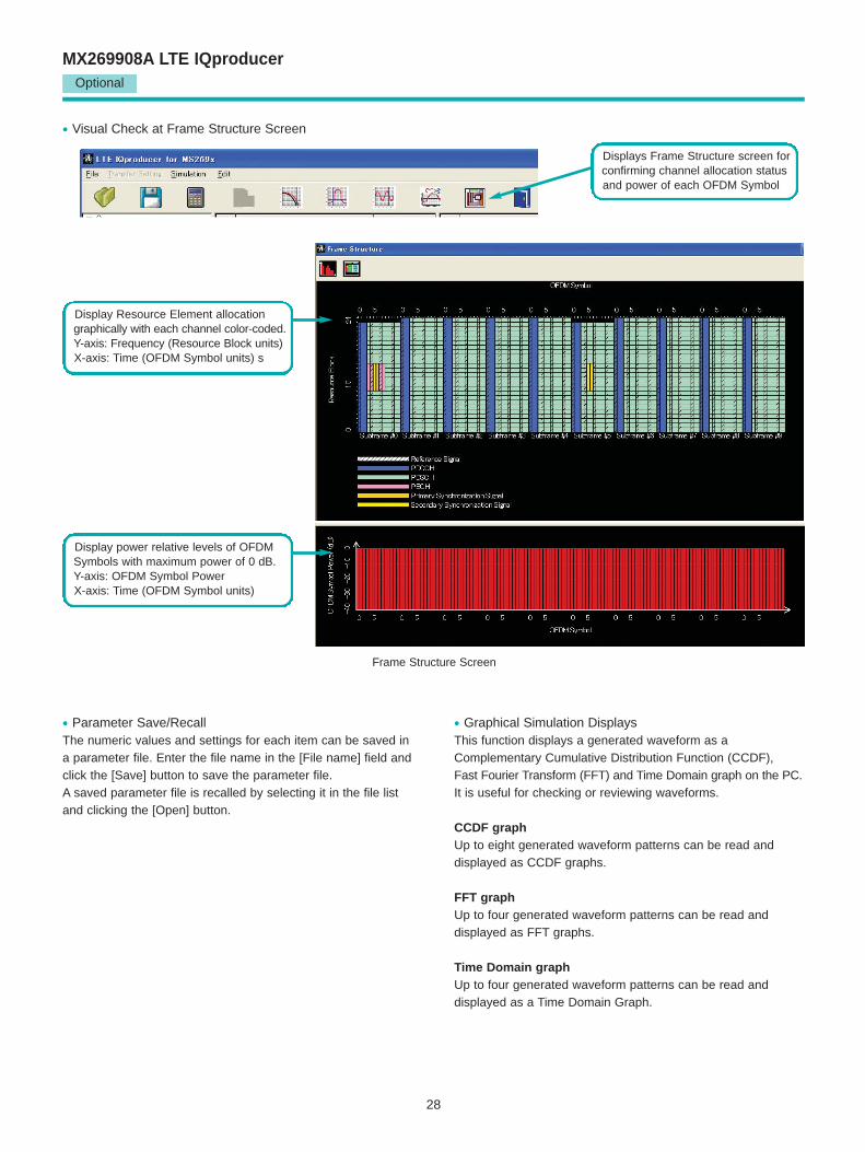
• Visual Check at Frame Structure Screen
• Graphical Simulation DisplaysThis function displays a generated waveform as aComplementary Cumulative Distribution Function (CCDF), Fast Fourier Transform (FFT) and Time Domain graph on the PC. It is useful for checking or reviewing waveforms.
CCDF graphUp to eight generated waveform patterns can be read and displayed as CCDF graphs.
FFT graphUp to four generated waveform patterns can be read and displayed as FFT graphs.
Time Domain graphUp to four generated waveform patterns can be read and displayed as a Time Domain Graph.
Displays Frame Structure screen forconfirming channel allocation statusand power of each OFDM Symbol
Display Resource Element allocationgraphically with each channel color-coded.Y-axis: Frequency (Resource Block units)X-axis: Time (OFDM Symbol units) s
Display power relative levels of OFDMSymbols with maximum power of 0 dB.Y-axis: OFDM Symbol PowerX-axis: Time (OFDM Symbol units)
Frame Structure Screen
MX269908A LTE IQproducer
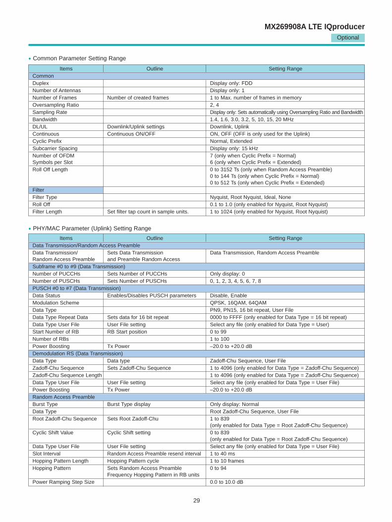
Items Outline Setting RangeCommonDuplex Display only: FDDNumber of Antennas Display only: 1Number of Frames Number of created frames 1 to Max. number of frames in memoryOversampling Ratio 2, 4Sampling Rate Display only: Sets automatically using Oversampling Ratio and BandwidthBandwidth 1.4, 1.6, 3.0, 3.2, 5, 10, 15, 20 MHzDL/UL Downlink/Uplink settings Downlink, UplinkContinuous Continuous ON/OFF ON, OFF (OFF is only used for the Uplink)Cyclic Prefix Normal, ExtendedSubcarrier Spacing Display only: 15 kHzNumber of OFDM 7 (only when Cyclic Prefix = Normal)Symbols per Slot 6 (only when Cyclic Prefix = Extended)Roll Off Length 0 to 3152 Ts (only when Random Access Preamble)
0 to 144 Ts (only when Cyclic Prefix = Normal)0 to 512 Ts (only when Cyclic Prefix = Extended)
FilterFilter Type Nyquist, Root Nyquist, Ideal, NoneRoll Off 0.1 to 1.0 (only enabled for Nyquist, Root Nyquist)Filter Length Set filter tap count in sample units. 1 to 1024 (only enabled for Nyquist, Root Nyquist)
Items Outline Setting RangeData Transmission/Random Access PreambleData Transmission/ Sets Data Transmission Data Transmission, Random Access PreambleRandom Access Preamble and Preamble Random AccessSubframe #0 to #9 (Data Transmission)Number of PUCCHs Sets Number of PUCCHs Only display: 0Number of PUSCHs Sets Number of PUSCHs 0, 1, 2, 3, 4, 5, 6, 7, 8PUSCH #0 to #7 (Data Transmission)Data Status Enables/Disables PUSCH parameters Disable, EnableModulation Scheme QPSK, 16QAM, 64QAMData Type PN9, PN15, 16 bit repeat, User FileData Type Repeat Data Sets data for 16 bit repeat 0000 to FFFF (only enabled for Data Type = 16 bit repeat)Data Type User File User File setting Select any file (only enabled for Data Type = User)Start Number of RB RB Start position 0 to 99Number of RBs 1 to 100Power Boosting Tx Power –20.0 to +20.0 dBDemodulation RS (Data Transmission)Data Type Data type Zadoff-Chu Sequence, User FileZadoff-Chu Sequence Sets Zadoff-Chu Sequence 1 to 4096 (only enabled for Data Type = Zadoff-Chu Sequence)Zadoff-Chu Sequence Length 1 to 4096 (only enabled for Data Type = Zadoff-Chu Sequence)Data Type User File User File setting Select any file (only enabled for Data Type = User File)Power Boosting Tx Power –20.0 to +20.0 dBRandom Access PreambleBurst Type Burst Type display Only display: NormalData Type Root Zadoff-Chu Sequence, User FileRoot Zadoff-Chu Sequence Sets Root Zadoff-Chu 1 to 839
(only enabled for Data Type = Root Zadoff-Chu Sequence)Cyclic Shift Value Cyclic Shift setting 0 to 839
(only enabled for Data Type = Root Zadoff-Chu Sequence)Data Type User File User File setting Select any file (only enabled for Data Type = User File)Slot Interval Random Access Preamble resend interval 1 to 40 msHopping Pattern Length Hopping Pattern cycle 1 to 10 framesHopping Pattern Sets Random Access Preamble 0 to 94
Frequency Hopping Pattern in RB unitsPower Ramping Step Size 0.0 to 10.0 dB
29
Optional
MX269908A LTE IQproducer
• Common Parameter Setting Range
• PHY/MAC Parameter (Uplink) Setting Range
Items Outline Setting RangeReference SignalOrthogonal Sequence Sets Orthogonal Sequence 0, 1, 2Random Sequence Sets used data to Random Sequence PN9, PN15, 16 bit repeat, User FileRandom Sequence Repeat Data Sets 16 bit repeat data 0000 to FFFF (only enabled for Random Sequence = 16 bit repeat)Random Sequence User File User File setting Select any file (only enabled for Random Sequence = User File)Frequency Shift Value 0, 1, 2, 3, 4, 5Power Boosting Tx Power –20.0 to +20.0 dBPBCHData Status Enables/Disables PBCH parameter Disable, EnableData Type PN9, PN15, 16 bit repeat, User FileData Type Repeat Data Sets 16 bit repeat data 0000 to FFFF (only enabled for Data Type = 16 bit repeat)Data Type User File User File setting Select any file (only enabled for Data Type = User File)Power Boosting Tx Power –20.0 to +20.0 dBSynchronization SignalsPrimary Synchronization SignalData Status Enables/Disables Primary Disable, Enable
Synchronization Signal parameterData Type Zadoff-Chu Sequence, User FileZadoff-Chu Sequence Sets Zadoff-Chu Sequence 1 to 128 (only enabled for Data Type = Zadoff-Chu Sequence)Zadoff-Chu Sequence Length Sets Zadoff-Chu Sequence Length 1 to 128 (only enabled for Data Type = Zadoff-Chu Sequence)Data Type User File User File setting Select any file (only enabled Data Type = User File)Power Boosting Tx Power –20.0 to +20.0 dBSecondary Synchronization SignalData Status Enables/Disables Secondary Disable, Enable
Synchronization Signal parameterData Type PN9, PN15, 16 bit repeat, User FileData Type Repeat Data 16 bit repeat data setting 0000 to FFFF (only enabled for Data Type = 16 bit repeat0Data Type User File User File setting Select any file (only enabled for Data Type = User File)Power Boosting Tx Power –20.0 to +20.0 dBSubframe #0 to #9Number of PDSCHs Sets Number of PDSCHs 1 to 64RB Arrangement PDSCH#0 to Number of PDSCHs –1PDCCHData Status Enables/Disables PDCCH parameter Disable, EnableNumber of OFDM Symbols for PDCCH 1, 2, 3 SymbolData Type PN9, PN15, 16 bit repeat, User FileData Type Repeat Data 16 bit repeat data setting 0000 to FFFF (only enabled for Data Type = 16 bit repeat)Data Type User File User File setting Select any file (only enabled for Data Type = User File)Power Boosting Tx Power –20.0 to +20.0 dBPDSCHData Status Enables/Disables PDSCH parameter Disable, EnableModulation Scheme QPSK, 16QAM, 64QAMData Type PN9, PN15, 16 bit repeat, User FileData Type Repeat Data 16 bit repeat setting 0000 to FFFF (only enabled for Data Type = 16 bit repeat)Data Type User File User File setting Select any file (only enabled for Data Type = User File)Power Boosting Tx Power –20.0 to +20.0 dBDL-SCHTransport Block Size Number of bits required by DL-SCH Only display: 0 bitData Type Only display: PN9
30
Optional
MX269908A LTE IQproducer
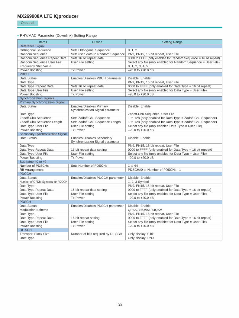
• PHY/MAC Parameter (Downlink) Setting Range
31
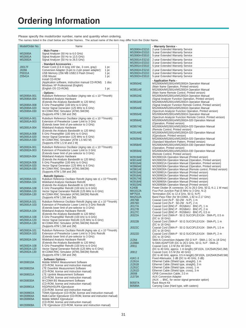
Ordering Information
Please specify the model/order number, name and quantity when ordering.The names listed in the chart below are Order Names. The actual name of the item may differ from the Order Name.
Model/Order No. Name
- Main Frame -MS2690A Signal Analyzer (50 Hz to 6.0 GHz)MS2691A Signal Analyzer (50 Hz to 13.5 GHz)MS2692A Signal Analyzer (50 Hz to 26.5 GHz)
- Standard Accessories -J0017F Power Cord (2.6 m long 100 Vac, 3 core, gray): 1 pcJ0266 Conversion Adapter (3-pin to 2-pin power adapter): 1 pcP0031A USB Memory (256 MB USB2.0 Flash Driver): 1 pcZ0541A USB Mouse: 1 pc
Install CD-ROM (Application software, instruction manual CD-ROM): 1 discWindows XP Professional (English)(English OS CD-ROM): 1 pc
- Options -MS2690A-001 Rubidium Reference Oscillator (Aging rate ±1 x 10⁻¹⁰/month)MS2690A-004 Wideband Analysis Hardware
(Extends the Analysis Bandwidth to 120 MHz)MS2690A-008 6 GHz Preamplifier (100 kHz to 6 GHz)MS2690A-020 Vector Signal Generator (125 MHz to 6 GHz)MS2690A-030 W-CDMA RNC Simulator (ATM1.5M/2M)
(Supports ATM 1.5M and 2M)
MS2691A-001 Rubidium Reference Oscillator (Aging rate ±1 x 10⁻¹⁰/month) MS2691A-003 Extension of Preselector Lower Limit to 3 GHz
(Extends lower limit of pre-selector to 3 GHz)MS2691A-004 Wideband Analysis Hardware
(Extends the Analysis Bandwidth to 120 MHz)MS2691A-008 6 GHz Preamplifier (100 kHz to 6 GHz) MS2691A-020 Vector Signal Generator (125 MHz to 6 GHz)MS2691A-030 W-CDMA RNC Simulator (ATM 1.5 M/2 M)
(Supports ATM 1.5 M and 2 M)
MS2692A-001 Rubidium Reference Oscillator (Aging rate ±1 x 10⁻¹⁰/month) MS2692A-003 Extension of Preselector Lower Limit to 3 GHz
(Extends lower limit of pre-selector to 3 GHz)MS2692A-004 Wideband Analysis Hardware
(Extends the Analysis Bandwidth to 120 MHz)MS2692A-008 6 GHz Preamplifier (100 kHz to 6 GHz)MS2692A-020 Vector Signal Generator (125 MHz to 6 GHz)MS2692A-030 W-CDMA RNC Simulator (ATM1.5M/2M)
(Supports ATM 1.5M and 2M)
- Retrofit Options -MS2690A-101 Rubidium Reference Oscillator Retrofit (Aging rate ±1 x 10⁻¹⁰/month)MS2690A-104 Wideband Analysis Hardware Retrofit
(Extends the Analysis Bandwidth to 120 MHz)MS2690A-108 6 GHz Preamplifier Retrofit (100 kHz to 6 GHz)MS2690A-120 Vector Signal Generator Retrofit (125 MHz to 6 GHz)MS2690A-130 W-CDMA RNC Simulator (ATM1.5M/2M) Retrofit
(Supports ATM 1.5M and 2M)
MS2691A-101 Rubidium Reference Oscillator Retrofit (Aging rate ±1 x 10⁻¹⁰/month)MS2691A-103 Extension of Preselector Lower Limit to 3 GHz Retrofit
(Extends lower limit of pre-selector to 3 GHz)MS2691A-104 Wideband Analysis Hardware Retrofit
(Extends the Analysis Bandwidth to 120 MHz)MS2691A-108 6 GHz Preamplifier Retrofit (100 kHz to 6 GHz)MS2691A-120 Vector Signal Generator Retrofit (125 MHz to 6 GHz)MS2691A-130 W-CDMA RNC Simulator (ATM1.5M/2M) Retrofit
(Supports ATM 1.5M and 2M)
MS2692A-101 Rubidium Reference Oscillator Retrofit (Aging rate ±1 x 10⁻¹⁰/month)MS2692A-103 Extension of Preselector Lower Limit to 3 GHz Retrofit
(Extends lower limit of pre-selector to 3 GHz)MS2692A-104 Wideband Analysis Hardware Retrofit
(Extends the Analysis Bandwidth to 120 MHz)MS2692A-108 6 GHz Preamplifier Retrofit (100 kHz to 6 GHz)MS2692A-120 Vector Signal Generator Retrofit (125 MHz to 6 GHz)MS2692A-130 W-CDMA RNC Simulator (ATM1.5M/2M) Retrofit
(Supports ATM 1.5M and 2M)
- Software Options -MX269010A Mobile WiMAX Measurement Software
(CD-ROM, license and instruction manual)MX269020A LTE Downlink Measurement Software
(CD-ROM, license and instruction manual)MX269021A LTE Upnlink Measurement Software
(CD-ROM, license and instruction manual)MX269030A W-CDMA BS Measurement Software
(CD-ROM, license and instruction manual)MX269901A HSDPA/HSUPA IQproducer
(CD-ROM, license and instruction manual)MX269902A TDMA IQproducer (CD-ROM, license and instruction manual)MX269904A Multi-Carrier IQproducer (CD-ROM, license and instruction manual)MX269905A Mobile WiMAX IQproducer
(CD-ROM, license and instruction manual)MX269908A LTE IQproducer (CD-ROM, license and instruction manual)
- Warranty Service -MS2690A-ES210 2-year Extended Warranty Service MS2690A-ES310 3-year Extended Warranty Service MS2690A-ES510 5-year Extended Warranty Service
MS2691A-ES210 2-year Extended Warranty Service MS2691A-ES310 3-year Extended Warranty Service MS2691A-ES510 5-year Extended Warranty Service
MS2692A-ES210 2-year Extended Warranty Service MS2692A-ES310 3-year Extended Warranty Service MS2692A-ES510 5-year Extended Warranty Service
- Application Parts -W2850AE MS2690A/MS2691A/MS2692A Operation Manual
(Main frame Operation, Printed version)W2851AE MS2690A/MS2691A/MS2692A Operation Manual
(Main frame Remote Control, Printed version)W2852AE MS2690A/MS2691A/MS2692A Operation Manual
(Signal Analyzer Function Operation, Printed version)W2853AE MS2690A/MS2691A/MS2692A Operation Manual
(Signal Analyzer Function Remote Control, Printed version)W2854AE MS2690A/MS2691A/MS2692A Operation Manual
(Spectrum Analyzer Function Operation, Printed version)W2855AE MS2690A/MS2691A/MS2692A Operation Manual
(Spectrum Analyzer Function Remote Control, Printed version)W2856AE MS2690A/MS2691A/MS2692A-020 Operation Manual
(Operation, Printed version)W2857AE MS2690A/MS2691A/MS2692A-020 Operation Manual
(Remote Control, Printed version)W2914AE MS2690A/MS2691A/MS2692A-020 Operation Manual
(IQproducer, Printed version)W2929AE MS2690A/MS2691A/MS2692A-020 Operation Manual
(Standard Waveform Pattern, Printed version)W2858AE MS2690A/MS2691A/MS2692A-030 Operation Manual
(Operation, Printed version)W2859AE MS2690A/MS2691A/MS2692A-030 Operation Manual
(Remote Control, Printed version)W2919AE MX269010A Operation Manual (Printed version)W3014AE MX269020A Operation Manual (Operation, Printed version)W3015AE MX269021A Operation Manual (Operation, Printed version)W2860AE MX269030A Operation Manual (Operation, Printed version)W2861AE MX269030A Operation Manual (Remote control, Printed version)W2915AE MX269901A Operation Manual (Printed version)W2916AE MX269902A Operation Manual (Printed version)W2917AE MX269904A Operation Manual (Printed version)W2918AE MX269905A Operation Manual (Printed version)W3023AE MX269908A Operation Manual (Printed version)K240B Power Divider (K connector, DC to 26.5 GHz, 50 Ω, K-J, 1 W max)MA1612A Four-Port Junction Pad (5 MHz to 3 GHz, N-J)MP752A Termination (DC to 12.4 GHz, 50 Ω, N-P)MA2512A Band Pass Filter (for W-CDMA, 1.92 to 2.17 GHz)J0576B Coaxial Cord (N-P · 5D-2W · N-P), 1 mJ0576D Coaxial Cord (N-P · 5D-2W · N-P), 2 mJ0127A Coaxial Cord (BNC-P · RG58A/U · BNC-P), 1 mJ0127B Coaxial Cord (BNC-P · RG58A/U · BNC-P), 2 mJ0127C Coaxial Cord (BNC-P · RG58A/U · BNC-P), 0.5 mJ0322A Coaxial Cord (SMA-P · 50 Ω SUCOFLEX104 · SMA-P), 0.5 m
(DC to 18 GHz)J0322B Coaxial Cord (SMA-P · 50 Ω SUCOFLEX104 · SMA-P), 1 m
(DC to 18 GHz) J0322C Coaxial Cord (SMA-P · 50 Ω SUCOFLEX104 · SMA-P), 1.5 m
(DC to 18 GHz)J0322D Coaxial Cord (SMA-P · 50 Ω SUCOFLEX104 · SMA-P), 2 m
(DC to 18 GHz)J1264 SMA-N Conversion Adapter (50 Ω N-P · SMA-J, DC to 18 GHz)J1398A N-SMA ADAPTOR (DC to 26.5 GHz, 50 Ω, N-P · SMA-J)J0911 Coaxial Cord, 1.0 M (for 40 GHz)
(DC to 40 GHz, approx. 1 m length) (SF102A, 11K254/K254/1.0M)J0912 Coaxial Cord, 0.5 M (for 40 GHz)
(DC to 40 GHz, approx. 0.5 m length) (SF102A, 11K254/K254/0.5M)41KC-3 Fixed Attenuator, 3 dB (DC to 40 GHz, 3 dB)J1261A Ethernet Cable (Shield type, straight), 1 mJ1261B Ethernet Cable (Shield type, straight), 3 mJ1261C Ethernet Cable (Shield type, cross), 1 mJ1261D Ethernet Cable (Shield type, cross), 3 mJ0008 GPIB Connection Cable, 2.0 mJ1373A AUX Conversion Adapter
(AUX → BNC, for vector signal generator option)B0597A Rack Mount KitB0589A Carrying Case (Hard type, with casters)
Anritsu Corporation5-1-1 Onna, Atsugi-shi, Kanagawa, 243-8555 JapanPhone: +81-46-223-1111Fax: +81-46-296-1264
• U.S.A.Anritsu Company1155 East Collins Blvd., Suite 100, Richardson, TX 75081, U.S.A.Toll Free: 1-800-267-4878Phone: +1-972-644-1777Fax: +1-972-671-1877
• CanadaAnritsu Electronics Ltd.700 Silver Seven Road, Suite 120, Kanata, Ontario K2V 1C3, CanadaPhone: +1-613-591-2003 Fax: +1-613-591-1006
• Brazil Anritsu Eletrônica Ltda.Praca Amadeu Amaral, 27 - 1 Andar01327-010-Paraiso-São Paulo-BrazilPhone: +55-11-3283-2511Fax: +55-11-3288-6940
• Mexico Anritsu Company, S.A. de C.V.Av. Ejército Nacional No. 579 Piso 9, Col. Granada11520 México, D.F., MéxicoPhone: +52-55-1101-2370Fax: +52-55-5254-3147
• U.K.Anritsu EMEA Ltd.200 Capability Green, Luton, Bedfordshire, LU1 3LU, U.K.Phone: +44-1582-433200 Fax: +44-1582-731303
• FranceAnritsu S.A.16/18 avenue du Québec-SILIC 72091961 COURTABOEUF CEDEX, FrancePhone: +33-1-60-92-15-50Fax: +33-1-64-46-10-65
• GermanyAnritsu GmbHNemetschek Haus, Konrad-Zuse-Platz 1 81829 München, Germany Phone: +49-89-442308-0 Fax: +49-89-442308-55
• ItalyAnritsu S.p.A.Via Elio Vittorini 129, 00144 Roma, ItalyPhone: +39-6-509-9711 Fax: +39-6-502-2425
• SwedenAnritsu ABBorgafjordsgatan 13, 164 40 KISTA, SwedenPhone: +46-8-534-707-00 Fax: +46-8-534-707-30
• FinlandAnritsu ABTeknobulevardi 3-5, FI-01530 VANTAA, FinlandPhone: +358-20-741-8100Fax: +358-20-741-8111
• DenmarkAnritsu A/SKirkebjerg Allé 90, DK-2605 Brøndby, DenmarkPhone: +45-72112200Fax: +45-72112210
• SpainAnritsu EMEA Ltd. Oficina de Representación en EspañaEdificio VeganovaAvda de la Vega, n˚ 1 (edf 8, pl 1, of 8)28108 ALCOBENDAS - Madrid, SpainPhone: +34-914905761Fax: +34-914905762
• United Arab EmiratesAnritsu EMEA Ltd.Dubai Liaison OfficeP O Box 500413 - Dubai Internet CityAl Thuraya Building, Tower 1, Suit 701, 7th FloorDubai, United Arab EmiratesPhone: +971-4-3670352Fax: +971-4-3688460
• SingaporeAnritsu Pte. Ltd.60 Alexandra Terrace, #02-08, The Comtech (Lobby A)Singapore 118502Phone: +65-6282-2400Fax: +65-6282-2533
• IndiaAnritsu Pte. Ltd. India Branch OfficeUnit No. S-3, Second Floor, Esteem Red Cross Bhavan,No. 26, Race Course Road, Bangalore 560 001, IndiaPhone: +91-80-32944707Fax: +91-80-22356648
• P.R. China (Hong Kong)Anritsu Company Ltd.Units 4 & 5, 28th Floor, Greenfield Tower, Concordia Plaza, No. 1 Science Museum Road, Tsim Sha Tsui East,Kowloon, Hong KongPhone: +852-2301-4980Fax: +852-2301-3545
• P.R. China (Beijing)Anritsu Company Ltd.Beijing Representative OfficeRoom 1515, Beijing Fortune Building, No. 5, Dong-San-Huan Bei Road, Chao-Yang District, Beijing 10004, P.R. ChinaPhone: +86-10-6590-9230Fax: +86-10-6590-9235
• KoreaAnritsu Corporation, Ltd.8F Hyunjuk Building, 832-41, Yeoksam Dong, Kangnam-ku, Seoul, 135-080, KoreaPhone: +82-2-553-6603Fax: +82-2-553-6604
• AustraliaAnritsu Pty. Ltd.Unit 21/270 Ferntree Gully Road, Notting Hill, Victoria 3168, AustraliaPhone: +61-3-9558-8177Fax: +61-3-9558-8255
• TaiwanAnritsu Company Inc.7F, No. 316, Sec. 1, Neihu Rd., Taipei 114, TaiwanPhone: +886-2-8751-1816Fax: +886-2-8751-1817
Specifications are subject to change without notice.
Catalog No. MX269xxxA-E-A-1-(2.00) Printed in Japan 2007-11 ddc/CDT
Please Contact:
071001
Printed on 70% Recycled Paper
Trademarks• IQproducer™ is a registered trademark of Anritsu Corporation.• MATLAB® is a registered trademark of The MathWorks, Inc.• Pentium® is registered trademarks of Intel Corporation or its subsidiaries in the USA and other countries.• Windows® is registered trademarks of Microsoft Corporation in the USA and other countries.• Other companies, product names and service names are registered trademarks of their respective companies.