ms3470 style – mil-dtl-26482 series ii crimp · 147. 26482 series. mil-tl-26482 series ii. for...
TRANSCRIPT
147
26
48
2 Series
MIL-D
TL-26
48
2 Series II
For Assistance in Europe – Please See the Back Cover For a Complete Listing of Our Branch Offices and Contact Numbers. • Specifications subject to change.
MS3470 Style – MIL-DTL-26482 Series II Crimp 26
48
2 Series
MIL-D
TL-26
48
2 Series II
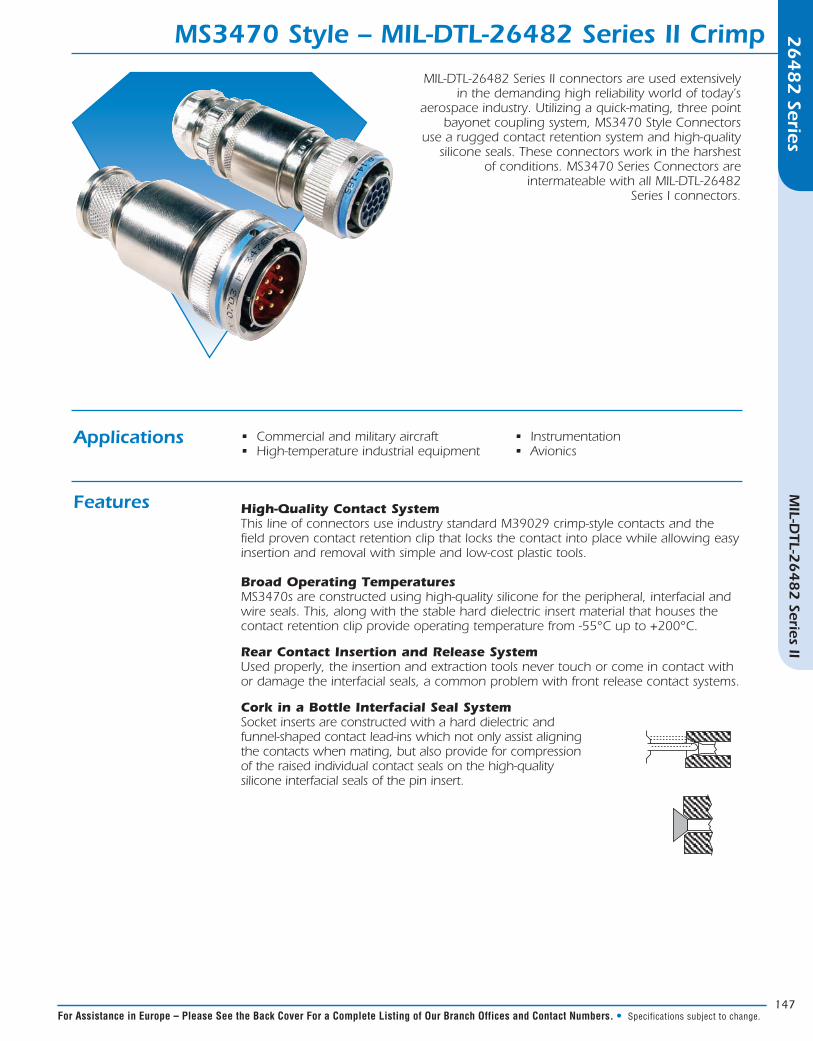
MIL-DTL-26482 Series II connectors are used extensively in the demanding high reliability world of today’s
aerospace industry. Utilizing a quick-mating, three point bayonet coupling system, MS3470 Style Connectors
use a rugged contact retention system and high-quality silicone seals. These connectors work in the harshest
of conditions. MS3470 Series Connectors are intermateable with all MIL-DTL-26482
Series I connectors.
Applications
Features
• Commercial and military aircraft• High-temperature industrial equipment
• Instrumentation• Avionics
High-Quality Contact SystemThis line of connectors use industry standard M39029 crimp-style contacts and the field proven contact retention clip that locks the contact into place while allowing easy insertion and removal with simple and low-cost plastic tools. Broad Operating Temperatures MS3470s are constructed using high-quality silicone for the peripheral, interfacial and wire seals. This, along with the stable hard dielectric insert material that houses the contact retention clip provide operating temperature from -55°C up to +200°C.
Rear Contact Insertion and Release System Used properly, the insertion and extraction tools never touch or come in contact with or damage the interfacial seals, a common problem with front release contact systems.
Cork in a Bottle Interfacial Seal System Socket inserts are constructed with a hard dielectric and funnel-shaped contact lead-ins which not only assist aligning the contacts when mating, but also provide for compression of the raised individual contact seals on the high-quality silicone interfacial seals of the pin insert.
148
26
48
2 Series
MIL-D
TL-26
48
2 Series II
In North America: Pricing Delivery: 800-642-8750 • Tech Support: 800-523-0727 • www.peigenesis.com • Specifications subject to change.
26
48
2 Series
MIL-D
TL-26
48
2 Series II
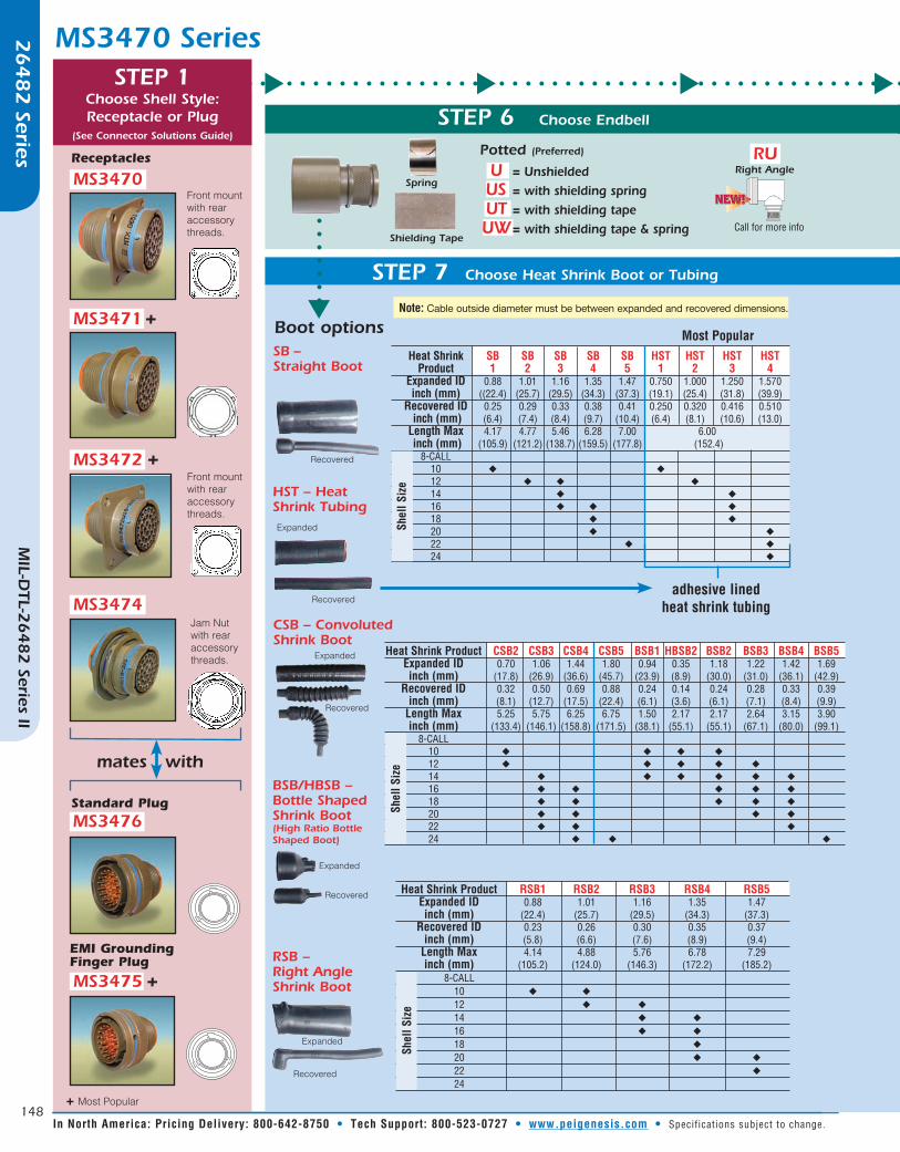
MS3470 Series
MS3470
MS3471
Receptacles
mates with
MS3475
+ Most Popular
t t t t
MS3472
Front mount with rear accessory threads.
+
Jam Nut with rear accessory threads.
+
+
MS3474
Front mount with rear accessory threads.
MS3476
Standard Plug
EMI Grounding Finger Plug
STEP 1Choose Shell Style:Receptacle or Plug
(See Connector Solutions Guide)
Heat Shrink Product CSB2 CSB3 CSB4 CSB5 BSB1 HBSB2 BSB2 BSB3 BSB4 BSB5 Expanded ID 0.70 1.06 1.44 1.80 0.94 0.35 1.18 1.22 1.42 1.69 inch (mm) (17.8) (26.9) (36.6) (45.7) (23.9) (8.9) (30.0) (31.0) (36.1) (42.9) Recovered ID 0.32 0.50 0.69 0.88 0.24 0.14 0.24 0.28 0.33 0.39 inch (mm) (8.1) (12.7) (17.5) (22.4) (6.1) (3.6) (6.1) (7.1) (8.4) (9.9) Length Max 5.25 5.75 6.25 6.75 1.50 2.17 2.17 2.64 3.15 3.90 inch (mm) (133.4) (146.1) (158.8) (171.5) (38.1) (55.1) (55.1) (67.1) (80.0) (99.1) 8-CALL 10 u u u u 12 u u u u u 14 u u u u u u 16 u u u u u 18 u u u u u 20 u u u u 22 u u u 24 u u u
Shel
l Siz
e
Heat Shrink Product RSB1 RSB2 RSB3 RSB4 RSB5 Expanded ID 0.88 1.01 1.16 1.35 1.47 inch (mm) (22.4) (25.7) (29.5) (34.3) (37.3) Recovered ID 0.23 0.26 0.30 0.35 0.37 inch (mm) (5.8) (6.6) (7.6) (8.9) (9.4) Length Max 4.14 4.88 5.76 6.78 7.29 inch (mm) (105.2) (124.0) (146.3) (172.2) (185.2) 8-CALL 10 u u 12 u u 14 u u 16 u u 18 u 20 u u
22 u
24
Shel
l Siz
e
Heat Shrink SB SB SB SB SB HST HST HST HST Product 1 2 3 4 5 1 2 3 4 Expanded ID 0.88 1.01 1.16 1.35 1.47 0.750 1.000 1.250 1.570 inch (mm) ((22.4) (25.7) (29.5) (34.3) (37.3) (19.1) (25.4) (31.8) (39.9) Recovered ID 0.25 0.29 0.33 0.38 0.41 0.250 0.320 0.416 0.510 inch (mm) (6.4) (7.4) (8.4) (9.7) (10.4) (6.4) (8.1) (10.6) (13.0) Length Max 4.17 4.77 5.46 6.28 7.00 6.00 inch (mm) (105.9) (121.2) (138.7) (159.5) (177.8) (152.4) 8-CALL
10 u u
12 u u u
14 u u
16 u u u
18 u u
20 u u
22 u u
24 u
Shel
l Siz
e
STEP 6 Choose Endbell
Spring U = Unshielded US = with shielding spring UT = with shielding tape UW = with shielding tape & spring
Potted (Preferred)
STEP 7 Choose Heat Shrink Boot or Tubing
Most Popular
Note: Cable outside diameter must be between expanded and recovered dimensions.tBoot options
CSB – Convoluted Shrink Boot
BSB/HBSB – Bottle Shaped Shrink Boot (High Ratio Bottle Shaped Boot)
RSB – Right Angle Shrink Boot
SB – Straight Boot
Expanded
Recovered
Expanded
Recovered
Recovered
Expanded
Recovered
HST – Heat Shrink TubingExpanded
Recoveredadhesive lined
heat shrink tubing
Shielding Tape
RU
Call for more info
Right Angle
149
26
48
2 Series
MIL-D
TL-26
48
2 Series II
For Assistance in Europe – Please See the Back Cover For a Complete Listing of Our Branch Offices and Contact Numbers. • Specifications subject to change.
26
48
2 Series
MIL-D
TL-26
48
2 Series II
STEP 6 Choose Endbell
STEP 7 Choose Conduit Adapter or Cord Grip
Size Code Size Code A R 1 2 3 Min Max Min Max Min Max Min Max Min Max PF* PS* MS* mm mm mm mm PL* ML* mm mm mm mm mm mm 8 - - - - - - - - - - 10 ♦ ♦ ♦ 5.0 10.0 3.0 7.0 ♦ ♦ 6.5 9.5 7.0 10.5 - - 12 ♦ ♦ ♦ 6.0 12.0 5.0 9.0 ♦ ♦ 6.5 9.5 8.5 10.5 - - 14 ♦ ♦ ♦ 10.0 14.0 7.0 12.0 ♦ ♦ 6.5 9.5 7.0 10.5 9.5 13.0 16 ♦ ♦ ♦ 10.0 14.0 7.0 12.0 ♦ ♦ 6.5 9.5 7.0 10.5 9.5 13.0 18 ♦ ♦ ♦ 10.0 14.0 7.0 12.0 ♦ ♦ 6.5 9.5 7.0 10.5 9.5 13.0 20 ♦ ♦ ♦ 13.0 18.0 9.0 16.0 ♦ ♦ 9.0 13.0 13.0 15.5 14.0 18.0 22 ♦ ♦ ♦ 13.0 18.0 9.0 16.0 ♦ ♦ 9.0 13.0 13.0 15.5 14.0 18.0 24 ♦ ♦ ♦ 13.0 18.0 9.0 16.0 9.0 13.0 13.0 15.5 14.0 18.0
Shel
l Siz
e
t t t
STEP 5Choose Alternate
Shell Position
(omit for normal)
WXYZ
STEP 4Choose Contact
P = PinS = SocketA = Less Pin ContactsB = Less Socket Contacts
A or B is used only for special contact types
(PC Pin, Thermocouple, Fiberoptic).
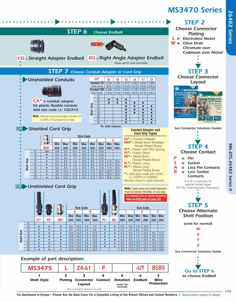
STEP 2
STEP 3Choose Connector
Layout
Choose Connector Plating
L = Electroless Nickel W = Olive Drab Chromate over Cadmium over Nickel
See Connector Solutions Guides
Example of part description:
(omit for normal)
1Shell Style
2Plating
7Wire
Protection
4Contact
5Rotation
6Endbell
MS3475 P -UT BSB53
ConnectorLayout
L 24-61
07 10 12 14 17 23 Conduit ID 0.256 0.394 0.472 0.563 0.650 0.906 Inch (mm) (6.5) (10.0) (12.0) (14.3) (16.5) (23.0) Conduit OD 0.394 0.512 0.622 0.728 0.835 1.122 Inch (mm) (10.0) (13.0) (15.8) (18.5) (21.2) (28.5) 8 10 u u u 12 u u u u u 14 u u u u
16 u u u u
18 u u u u 20 R R u
22 R R u
24 R R u
Shel
l Siz
e
CA*
R= with reducer
See Connector Solutions Guide
t
t
t
t
Go to STEP 6
(See Connector Solutions Guide)
CG = Straight Adapter Endbell RG = Right Angle Adapter Endbell
Unshielded Conduits
CA* = conduit adapter for plastic flexible conduit. Add size code i.e. CGCA10
t
Note: Normal recommended conduit fill is 40% of Conduit ID or less.
Shielded Cord GriptOR
Unshielded Cord GriptOR
Size Code 1 1 2 3 4 Min Max Min Max Min Max Min Max MSS* mm mm mm mm mm mm mm mm 8 Call 4.0 6.5 6.5 9.5 8.0 10.5 - - 10 ♦ 6.5 9.5 8.0 10.5 9.0 13.0 - - 12 ♦ 6.5 9.5 7.0 10.5 9.0 13.0 - - 14 ♦ 6.5 9.5 7.0 10.5 9.0 13.0 11.5 15.5 16 ♦ 6.5 9.5 7.0 10.5 9.0 13.0 11.5 15.5 18 ♦ 6.5 9.5 7.0 10.5 9.0 13.0 11.5 15.5 20 ♦ 9.0 13.0 11.5 15.5 17.0 20.0 20.0 25.0 22 ♦ 9.0 13.0 11.5 15.5 17.0 20.0 20.0 25.0 24 ♦ 9.0 13.0 11.5 15.5 17.0 20.0 20.0 25.0
Shel
l Siz
e
MS3470 Series
Conduit Adapter and Cord Grip Types
CA*= Conduit AdapterMSS*= Metal Short Shielded - Nickel Plated BrassPF*= Plastic with Flex SpringPS*= Plastic ShortMS*= Metal Short - Nickel Plated BrassPL*= Plastic LongML*= Metal Long - Nickel Plated Brass*= add size code per chart i.e. CGPFA or CGMSS4 Min/Max refers to cable diameter.
to choose Endbell
Note: Cable jacket and shield diameters must be between Min/Max of cord grip. For detailed info on shield diameters, ➥see MSS table on page 232.
Please call for more information

150
26
48
2 Series
MIL-D
TL-26
48
2 Series II
In North America: Pricing Delivery: 800-642-8750 • Tech Support: 800-523-0727 • www.peigenesis.com • Specifications subject to change.
MIL-DTL-26482 Series II – Dimensions26
48
2 Series
MIL-D
TL-26
48
2 Series II
Overall E Rear Shell A Diameter Length B Max J Max R (TP) S Max Y Max Thread Size Max L Max MS3470/71 MS3472 MS3470/71/72 MS3470 MS3472 MS3470/71 MS3472 MS3471 UNEF-2A 8 .474 1.215 .462 .493 .078 .594 .734 .828 1.065 .958 1/2-20
(12.04) (30.86) (11.73) (12.52) (1.98) (15.09) (18.64) (21.03) (27.05) (24.33)
10 .591 1.215 .462 .493 .078 .719 .812 .954 1.141 1.082 5/8-24
(15.01) (30.86) (11.73) (12.52) (1.98) (18.26) (20.62) (24.23) (28.98) (27.48)
12 .751 1.215 .462 .493 .078 .812 .938 1.047 1.266 1.176 3/4-20
(19.08) (30.86) (11.73) (12.52) (1.98) (20.62) (23.93) (26.59) (32.16) (29.87)
14 .876 1.215 .462 .493 .078 .906 1.031 1.141 1.360 1.270 7/8-20
(22.25) (30.86) (11.73) .493 (12.52) .078 (1.98) (23.01) (26.19) (28.98) (34.54) (32.26)
16 1.001 1.215 .46 .493 .078 .969 1.125 1.234 1.453 1.364 1-20
(25.43) 30.86) (11.73) (12.52) (1.98) (24.61) (28.58) (31.34) (36.91) (34.64)
18 1.126 1.215 .462 .493 .078 1.062 1.203 1.328 1.532 1.458 1-1/16-18
(28.60) (30.86) (11.73) (12.52) (1.98) (26.97) (30.56) (33.73) (38.91) (37.03)
20 1.251 1.275 .587 .587 .110 1.156 1.297 1.453 1.688 1.708 1-3/16-18
(31.78) (32.40) (14.91) (14.91) (2.79) (29.36) (32.94) (36.91) (42.88) (43.38)
22 1.376 1.275 .587 .587 .110 1.250 1.375 1.578 1.766 1.708 1-5/16-18
(34.95) (32.40) (14.91) (14.91) (2.79) (31.75) (34.93) (40.08) (44.86) (43.38)
24 1.501 1.275 .620 .620 .110 1.375 1.500 1.703 1.891 1.832 1-7/16-18
(38.130) (32.40) (15.75) (15.75) (2.79) (34.93) (38.10) (43.26) (48.03) (46.53)
Receptacles
MS3470 - Flanged MS3471 - Flanged MS3472 - Cable Connecting
All dimensions in inches (millimeters in parenthesis)

151
26
48
2 Series
MIL-D
TL-26
48
2 Series II
For Assistance in Europe – Please See the Back Cover For a Complete Listing of Our Branch Offices and Contact Numbers. • Specifications subject to change.
Dimensions – MIL-DTL-26482 Series II 26
48
2 Series
MIL-D
TL-26
48
2 Series II
Shell Size D ∅ LF Max K Max Z∅ Cable Max* BB∅ Max C Code 10 0.740 2.193 0.118 0.512 0.833 D (18.8) (55.7) (3.0) (13.0) (21.2) 12 0.865 2.173 0.118 0.551 0.887 D (22.0) (55.2) (3.0) (14.0) (22.6) 14 0.990 2.232 0.118 0.709 0.989 E (25.2) (56.7) (3.0) (18.0) (25.1) 16 1.146 2.390 0.118 0.709 0.989 E (29.1) (60.7) (3.0) (18.0) (25.1) 18 1.271 2.311 0.118 0.755 1.114 F (32.3) (58.7) (3.0) (19.2) (28.3) 20 1.428 2.409 0.118 0.974 1.270 G (36.3) (61.2) (3.0) (24.7) (32.3) 22 1.552 2.528 0.118 0.956 1.395 H (39.4) (64.2) (3.0) (24.3) (35.4) 24 1.552 2.606 0.118 0.956 1.395 H (39.4) (66.2) (3.0) (24.3) (35.4)
K
JJBBZ
UNCC-PG
L�
D± .003(0.08)
125
UNAC-PG
K
Z BB JJ
L�
D± .003(0.08)
125
Shell Size D ∅ LF Max K Max Z∅ Cable Max* BB∅ Max JJ∅ Max C Code 10 0.740 2.614 0.433 0.337 0.493 0.588 B (18.8) (66.4) (11.0) (8.6) (12.5) (14.9) 12 0.865 2.496 0.476 0.506 0.655 0.783 C (22.0) (63.4) (12.1) (12.9) (16.9) (19.9) 14 0.990 2.496 0.476 0.619 0.807 0.926 D (25.1) (63.4) (12.1) (15.7) (20.5) (23.5) 16 1.146 2.697 0.476 0.619 0.821 0.939 E (29.1) (68.5) (12.1) (15.7) (20.9) (23.9) 18 1.271 2.744 0.476 0.675 0.891 1.010 F (32.3) (69.7) (12.1) (17.1) (22.6) (25.6) 20 1.428 2.783 0.476 0.731 0.954 1.072 G (36.3) (70.7) (12.1) (18.6) (24.2) (27.2) 22 1.552 2.886 0.476 0.843 1.095 1.213 H (39.4) (73.3) (12.1) (21.4) (27.8) (30.8) 24 2.552 2.933 0.476 0.900 1.157 1.276 H (39.4) (74.5) (12.1) (22.8) (29.4) (32.4)
L F is the maximum reference length from the mating face of the connector* Recommended cable maximum is 90% of actual endbell I.D.All dimensions in inches (millimeters in parenthesis)
Universal Heat Shrink
Cord Grip
152
26
48
2 Series
MIL-D
TL-26
48
2 Series II
In North America: Pricing Delivery: 800-642-8750 • Tech Support: 800-523-0727 • www.peigenesis.com • Specifications subject to change.
MIL-DTL-26482 Series II – Dimensions26
48
2 Series
MIL-D
TL-26
48
2 Series II
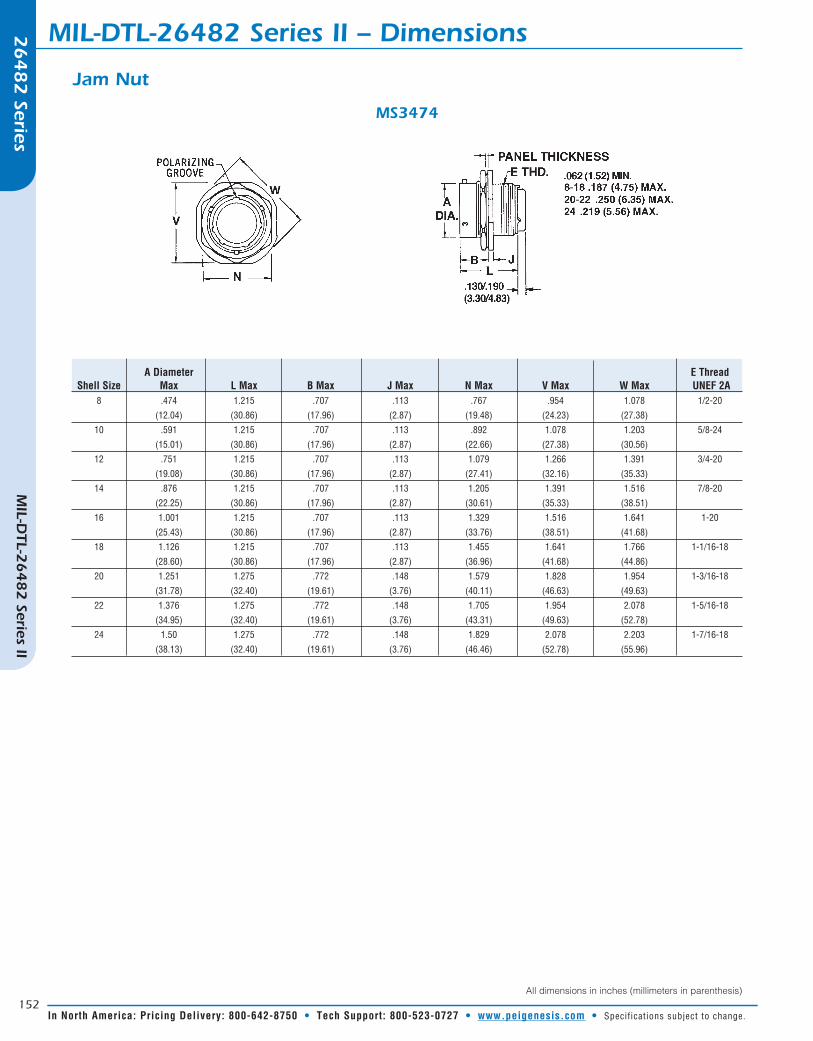
A Diameter E Thread Shell Size Max L Max B Max J Max N Max V Max W Max UNEF 2A 8 .474 1.215 .707 .113 .767 .954 1.078 1/2-20
(12.04) (30.86) (17.96) (2.87) (19.48) (24.23) (27.38)
10 .591 1.215 .707 .113 .892 1.078 1.203 5/8-24
(15.01) (30.86) (17.96) (2.87) (22.66) (27.38) (30.56)
12 .751 1.215 .707 .113 1.079 1.266 1.391 3/4-20
(19.08) (30.86) (17.96) (2.87) (27.41) (32.16) (35.33)
14 .876 1.215 .707 .113 1.205 1.391 1.516 7/8-20
(22.25) (30.86) (17.96) (2.87) (30.61) (35.33) (38.51)
16 1.001 1.215 .707 .113 1.329 1.516 1.641 1-20
(25.43) (30.86) (17.96) (2.87) (33.76) (38.51) (41.68)
18 1.126 1.215 .707 .113 1.455 1.641 1.766 1-1/16-18
(28.60) (30.86) (17.96) (2.87) (36.96) (41.68) (44.86)
20 1.251 1.275 .772 .148 1.579 1.828 1.954 1-3/16-18
(31.78) (32.40) (19.61) (3.76) (40.11) (46.63) (49.63)
22 1.376 1.275 .772 .148 1.705 1.954 2.078 1-5/16-18
(34.95) (32.40) (19.61) (3.76) (43.31) (49.63) (52.78)
24 1.50 1.275 .772 .148 1.829 2.078 2.203 1-7/16-18
(38.13) (32.40) (19.61) (3.76) (46.46) (52.78) (55.96)
Jam Nut
MS3474
All dimensions in inches (millimeters in parenthesis)

153
26
48
2 Series
MIL-D
TL-26
48
2 Series II
For Assistance in Europe – Please See the Back Cover For a Complete Listing of Our Branch Offices and Contact Numbers. • Specifications subject to change.
Dimensions – MIL-DTL-26482 Series II 26
48
2 Series
MIL-D
TL-26
48
2 Series II
Shell Size D ∅ LF Max K Max Z∅ Cable Max* BB∅ Max C Code 10 0.740 2.193 0.118 0.512 0.833 D (18.8) (55.7) (3.0) (13.0) (21.2) 12 0.865 2.173 0.118 0.551 0.887 D (22.0) (55.2) (3.0) (14.0) (22.6) 14 0.990 2.232 0.118 0.709 0.989 E (25.2) (56.7) (3.0) (18.0) (25.1) 16 1.146 2.390 0.118 0.709 0.989 E (29.1) (60.7) (3.0) (18.0) (25.1) 18 1.271 2.311 0.118 0.755 1.114 F (32.3) (58.7) (3.0) (19.2) (28.3) 20 1.428 2.409 0.118 0.974 1.270 G (36.3) (61.2) (3.0) (24.7) (32.3) 22 1.552 2.528 0.118 0.956 1.395 H (39.4) (64.2) (3.0) (24.3) (35.4) 24 1.552 2.606 0.118 0.956 1.395 H (39.4) (66.2) (3.0) (24.3) (35.4)
K
JJBBZ
UNCC-PG
L�
D± .003(0.08)
125
UNAC-PG
K
Z BB JJ
L�
D± .003(0.08)
125
Shell Size D ∅ LF Max K Max Z∅ Cable Max* BB∅ Max JJ∅ Max C Code 10 0.740 2.614 0.433 0.337 0.493 0.588 B (18.8) (66.4) (11.0) (8.6) (12.5) (14.9) 12 0.865 2.496 0.476 0.506 0.655 0.783 C (22.0) (63.4) (12.1) (12.9) (16.9) (19.9) 14 0.990 2.496 0.476 0.619 0.807 0.926 D (25.1) (63.4) (12.1) (15.7) (20.5) (23.5) 16 1.146 2.697 0.476 0.619 0.821 0.939 E (29.1) (68.5) (12.1) (15.7) (20.9) (23.9) 18 1.271 2.744 0.476 0.675 0.891 1.010 F (32.3) (69.7) (12.1) (17.1) (22.6) (25.6) 20 1.428 2.783 0.476 0.731 0.954 1.072 G (36.3) (70.7) (12.1) (18.6) (24.2) (27.2) 22 1.552 2.886 0.476 0.843 1.095 1.213 H (39.4) (73.3) (12.1) (21.4) (27.8) (30.8) 24 2.552 2.933 0.476 0.900 1.157 1.276 H (39.4) (74.5) (12.1) (22.8) (29.4) (32.4)
Universal Heat Shrink
Cord Grip
L F is the maximum reference length from the mating face of the connector* Recommended cable maximum is 90% of actual endbell I.D.All dimensions in inches (millimeters in parenthesis)

154
26
48
2 Series
MIL-D
TL-26
48
2 Series II
In North America: Pricing Delivery: 800-642-8750 • Tech Support: 800-523-0727 • www.peigenesis.com • Specifications subject to change.
MIL-DTL-26482 Series II – Dimensions
Shell A Diameter U Diameter E Rear Thread Size Max Max L Max UNEF-2A 8 .765 .782 1.230 1/2-20
(19.43) (19.86) (31.24)
10 .840 .926 1.230 5/8-24
(21.34) (23.52) (31.24)
12 .999 1.043 1.230 3/4-20
(25.37) (26.49) (31.24)
14 1.139 1.183 1.230 7/8-20
(28.93) (30.05) (31.24)
16 1.261 1.305 1.230 1-20
(32.03) (33.15) (31.24)
18 1.337 1.391 1.230 1-1/16-18
(33.96) (35.33) (31.24)
20 1.477 1.531 1.230 1-3/16-18
(37.52) (38.89) (31.24)
22 1.602 1.656 1.230 1-5/16-18
(40.69) (42.06) 31.24)
24 1.723 1.777 1.230 1-7/16-18
(43.76) (45.14) (31.24)
Plugs
MS3476/MS3475
All dimensions in inches (millimeters in parenthesis)
155
26
48
2 Series
MIL-D
TL-26
48
2 Series II
For Assistance in Europe – Please See the Back Cover For a Complete Listing of Our Branch Offices and Contact Numbers. • Specifications subject to change.
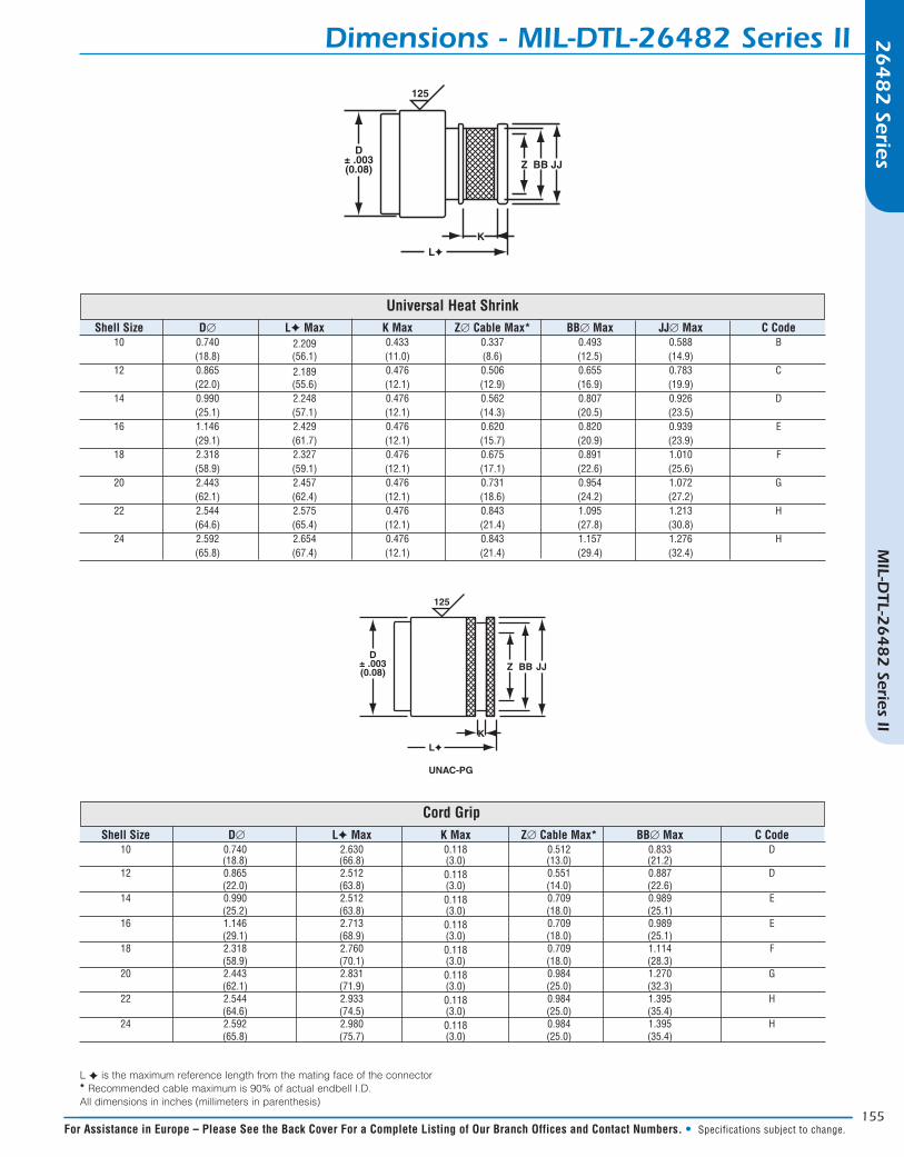
Dimensions - MIL-DTL-26482 Series II
Shell Size D∅ LF Max K Max Z∅ Cable Max* BB∅ Max C Code 10 0.740 2.630 0.118 0.512 0.833 D (18.8) (66.8) (3.0) (13.0) (21.2) 12 0.865 2.512 0.118 0.551 0.887 D (22.0) (63.8) (3.0) (14.0) (22.6) 14 0.990 2.512 0.118 0.709 0.989 E (25.2) (63.8) (3.0) (18.0) (25.1) 16 1.146 2.713 0.118 0.709 0.989 E (29.1) (68.9) (3.0) (18.0) (25.1) 18 2.318 2.760 0.118 0.709 1.114 F (58.9) (70.1) (3.0) (18.0) (28.3) 20 2.443 2.831 0.118 0.984 1.270 G (62.1) (71.9) (3.0) (25.0) (32.3) 22 2.544 2.933 0.118 0.984 1.395 H (64.6) (74.5) (3.0) (25.0) (35.4) 24 2.592 2.980 0.118 0.984 1.395 H (65.8) (75.7) (3.0) (25.0) (35.4)
K
JJBBZ
UNCC-PG
L�
D± .003(0.08)
125
UNAC-PG
K
Z BB JJ
L�
D± .003(0.08)
125
Shell Size D∅ LF Max K Max Z∅ Cable Max* BB∅ Max JJ∅ Max C Code 10 0.740 2.209 0.433 0.337 0.493 0.588 B (18.8) (56.1) (11.0) (8.6) (12.5) (14.9) 12 0.865 2.189 0.476 0.506 0.655 0.783 C (22.0) (55.6) (12.1) (12.9) (16.9) (19.9) 14 0.990 2.248 0.476 0.562 0.807 0.926 D (25.1) (57.1) (12.1) (14.3) (20.5) (23.5) 16 1.146 2.429 0.476 0.620 0.820 0.939 E (29.1) (61.7) (12.1) (15.7) (20.9) (23.9) 18 2.318 2.327 0.476 0.675 0.891 1.010 F (58.9) (59.1) (12.1) (17.1) (22.6) (25.6) 20 2.443 2.457 0.476 0.731 0.954 1.072 G (62.1) (62.4) (12.1) (18.6) (24.2) (27.2) 22 2.544 2.575 0.476 0.843 1.095 1.213 H (64.6) (65.4) (12.1) (21.4) (27.8) (30.8) 24 2.592 2.654 0.476 0.843 1.157 1.276 H (65.8) (67.4) (12.1) (21.4) (29.4) (32.4)
Cord Grip
Universal Heat Shrink
L F is the maximum reference length from the mating face of the connector* Recommended cable maximum is 90% of actual endbell I.D.All dimensions in inches (millimeters in parenthesis)

156
26
48
2 Series
MIL-D
TL-26
48
2 Series II
In North America: Pricing Delivery: 800-642-8750 • Tech Support: 800-523-0727 • www.peigenesis.com • Specifications subject to change.
MIL-DTL-26482 Series II – Contacts26
48
2 Series
Contact Wire Size Pin Wire Strip Wire Insulation Wire Hole Size Awg Contact Color Bands Lengths Range Filler Color Part Number 1 2 3 Min Max 20 20 - 24 M39029/4-110 Brown Brown Black 3/16 .040 .083 MS27488-20-2 Red (4.77) (1.02) (2.11)
16 16 - 20 M39029/4-111 Brown Brown Brown 9/32 .053 .103 MS27488-16-2 Blue (7.14) (1.35) (2.62)
12 12 - 14 M39029/4-113 Brown Brown Orange 9/32 .097 .158 MS27488-12-2 Yellow (7.14) (2.46) (4.01)
Pins
Head goes in first, trim excess
Contact Wire Size Socket Wire Strip Wire Insulation Wire Hole Size Awg Contact Color Bands Lengths Range Filler Color Part Number 1 2 3 Min Max 20 20 - 24 M39029/5-115 Brown Brown Green 3/16 .040 .083 MS27488-20-2 Red (4.77) (1.02) (2.11)
16 16 - 20 M39029/5-116 Brown Brown Blue 9/32 .053 .103 MS27488-16-2 Blue (7.14) (1.35) (2.62)
12 12 - 14 M39029/5-118 Brown Brown Grey 9/32 .097 .158 MS27488-12-2 Yellow (7.14) (2.46) (4.01)
Sockets
Head goes in first, trim excess

157
26
48
2 Series
MIL-D
TL-26
48
2 Series II
For Assistance in Europe – Please See the Back Cover For a Complete Listing of Our Branch Offices and Contact Numbers. • Specifications subject to change.
Contacts – MIL-DTL-26482 Series II 26
48
2 Series
Pins
Metal Plastic Hand Crimp Power Crimp Turret Heads Use Locator Insertion Extraction Insertion/Extraction Insertion Extraction Tool Tool Color Tool Tool Tool Tip Color Tip Color
M22520/1-01 WA27F== M22520/1-02 Red DAK83-20B DRK83-20B M81969/14-11 Red White
M22520/1-01 WA27F== M22520/1-02 Blue DAK83-16B DRK83-16B M81969/14-03 Blue White
M22520/1-01 WA27F== M22520/1-02 Yellow DAK83-12B DRK83-12B M81969/14-04 Yellow White
== Call for more tool accessories.
Sockets
Metal Plastic Hand Crimp Power Crimp Turret Heads Use Locator Insertion Extraction Insertion/Extraction Insertion Extraction Tool Tool Color Tool Tool Tool Tip Color Tip Color
M22520/1-01 WA27F== M22520/1-02 Red DAK83-20B DRK83-20B M81969/14-11 Red White
M22520/1-01 WA27F== M22520/1-02 Blue DAK83-16B DRK83-16B M81969/14-03 Blue White
M22520/1-01 WA27F== M22520/1-02 Yellow DAK83-12B DRK83-12B M81969/14-04 Yellow White
== Call for more tool accessories.

158
26
48
2 Series
MIL-D
TL-26
48
2 Series II
In North America: Pricing Delivery: 800-642-8750 • Tech Support: 800-523-0727 • www.peigenesis.com • Specifications subject to change.
MIL-DTL-26482 Series II – At-A-GlanceAdditional Connector Information
Name:
Company:
Email:
Phone:
CONNECTOR Part #: _______________________________________________
OR# of Contacts: _______________________________________ Sizes & Type:____________________________
CABLE Manufacturer: ________________________________________________________________________ (If Known)
CABLE Part #: _____________________________________ OR Cable OD:____________________________
Use endbell “U” for Menus A, B, C, D & E
Qty: EAU:
Use endbell “CG” for Menus F, G & H
Crimp Termination Only
Comments/Notes:
Choose One Connector Choose One Endbell Choose One Wire Protection