m.s.4706-451-11 - addendum no. 2 - surrey · station 2 upgrade issued september 20, 2013 addendum...
TRANSCRIPT

CONTRACTM.S.4706‐4510‐11CITYOFSURREY
MORGANCREEKPUMPSTATION2UPGRADE
ISSUEDSEPTEMBER20,2013
ADDENDUMNo.2
ThisaddendumformspartoftheContractDocumentsandshallberead,interpretedandcoordinatedwithallotherparts.ThecostsofallworkcontainedhereinshallbeincludedintheContractPrice.ThefollowingrevisionssupersedetheinformationcontainedintheoriginalContractDocumenttotheextentreferencedandshallbecomepartthereof.TenderersshallacknowledgereceiptofthisaddendumbyinsertingitsnumberanddatewhereprovidedforontheFormofTender.Thisaddendumcontains2pagesand3attachments.1.0 FormofTenderAgreement–SectionC
SectionC–Agreement,doesnotneedtobesubmittedwiththetenderpackage.(8pagesintotal)
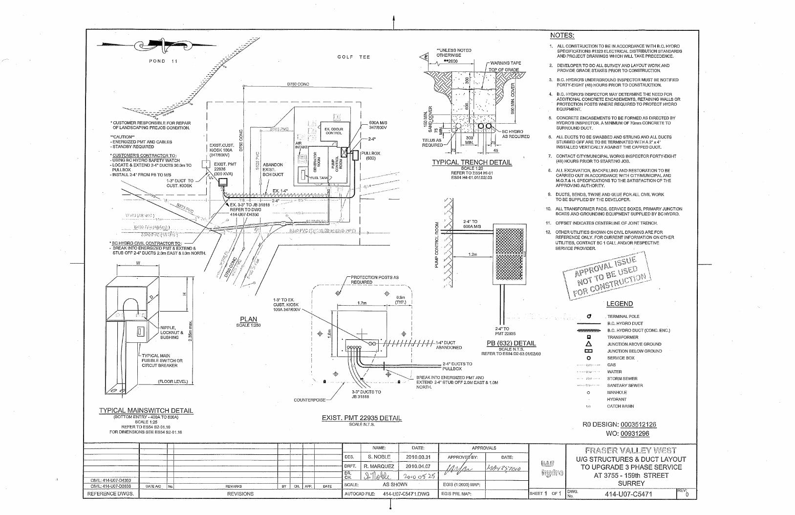
2.0 NewDrawingsBCHydroReferenceDrawing
SeeattachedBCHydroDrawing414‐U07‐C5471fordetailsonBCHydroconduitinstallation.
StructuralSketchforRoofAnchors
Seeattachedsketchfordetailsonframinganchorinstallation.3.0 NewSpecificationsSectionSection15800–Sluice&FlapGates
AddedtoTenderDocumentsandattachedtoAddendum4.0 ModificationstoExistingSpecificationsSection01100–SpecialProvisions Item1.7
IgnorereferencetoKennedyPumpStation–thisshouldrefertoMorganCreekPumpStation2
CONTRACTM.S.4706‐4510‐11
ADDENDUMNo.2
Page2of2
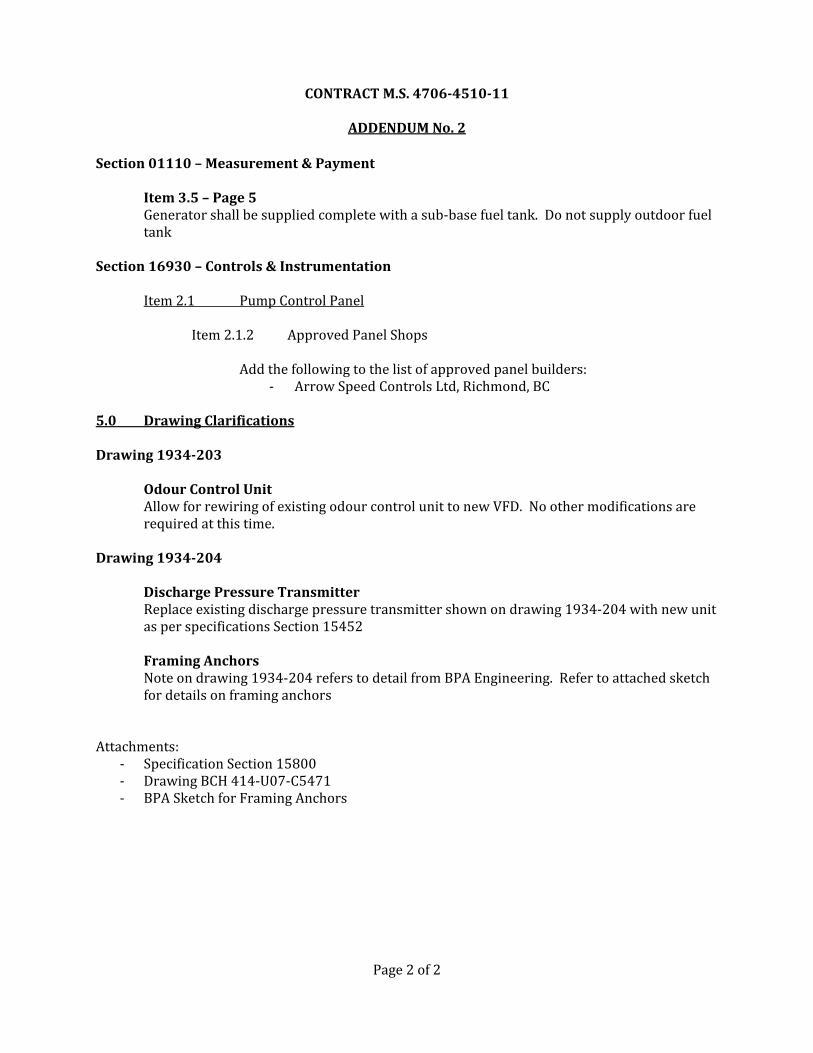
Section01110–Measurement&Payment Item3.5–Page5
Generatorshallbesuppliedcompletewithasub‐basefueltank.Donotsupplyoutdoorfueltank
Section16930–Controls&Instrumentation
Item2.1 PumpControlPanel
Item2.1.2 ApprovedPanelShops Addthefollowingtothelistofapprovedpanelbuilders:
‐ ArrowSpeedControlsLtd,Richmond,BC5.0 DrawingClarificationsDrawing1934‐203 OdourControlUnit
AllowforrewiringofexistingodourcontrolunittonewVFD.Noothermodificationsarerequiredatthistime.
Drawing1934‐204 DischargePressureTransmitter
Replaceexistingdischargepressuretransmittershownondrawing1934‐204withnewunitasperspecificationsSection15452FramingAnchorsNoteondrawing1934‐204referstodetailfromBPAEngineering.Refertoattachedsketchfordetailsonframinganchors
Attachments:
‐ SpecificationSection15800‐ DrawingBCH414‐U07‐C5471‐ BPASketchforFramingAnchors
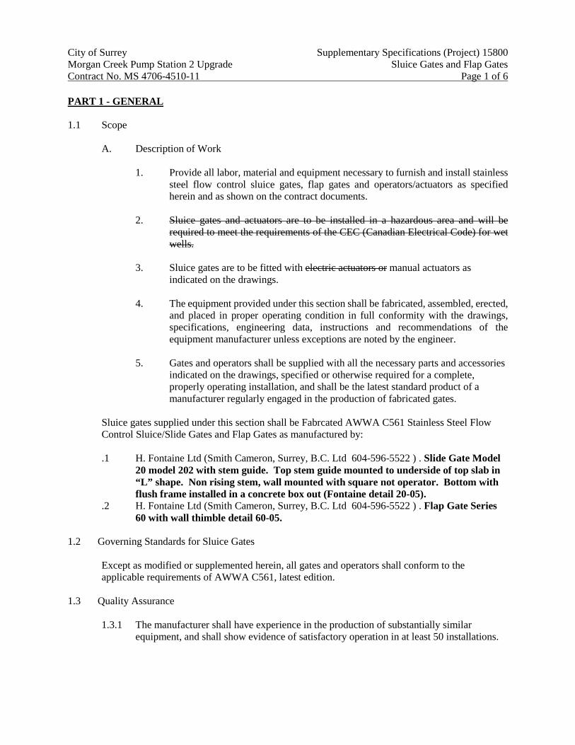
City of Surrey Supplementary Specifications (Project) 15800 Morgan Creek Pump Station 2 Upgrade Sluice Gates and Flap Gates Contract No. MS 4706-4510-11 Page 1 of 6 PART 1 - GENERAL 1.1 Scope
A. Description of Work
1. Provide all labor, material and equipment necessary to furnish and install stainless steel flow control sluice gates, flap gates and operators/actuators as specified herein and as shown on the contract documents.
2. Sluice gates and actuators are to be installed in a hazardous area and will be
required to meet the requirements of the CEC (Canadian Electrical Code) for wet wells.
3. Sluice gates are to be fitted with electric actuators or manual actuators as
indicated on the drawings.
4. The equipment provided under this section shall be fabricated, assembled, erected, and placed in proper operating condition in full conformity with the drawings, specifications, engineering data, instructions and recommendations of the equipment manufacturer unless exceptions are noted by the engineer.
5. Gates and operators shall be supplied with all the necessary parts and accessories
indicated on the drawings, specified or otherwise required for a complete, properly operating installation, and shall be the latest standard product of a manufacturer regularly engaged in the production of fabricated gates.
Sluice gates supplied under this section shall be Fabrcated AWWA C561 Stainless Steel Flow Control Sluice/Slide Gates and Flap Gates as manufactured by: .1 H. Fontaine Ltd (Smith Cameron, Surrey, B.C. Ltd 604-596-5522 ) . Slide Gate Model
20 model 202 with stem guide. Top stem guide mounted to underside of top slab in “L” shape. Non rising stem, wall mounted with square not operator. Bottom with flush frame installed in a concrete box out (Fontaine detail 20-05).
.2 H. Fontaine Ltd (Smith Cameron, Surrey, B.C. Ltd 604-596-5522 ) . Flap Gate Series 60 with wall thimble detail 60-05.
1.2 Governing Standards for Sluice Gates
Except as modified or supplemented herein, all gates and operators shall conform to the applicable requirements of AWWA C561, latest edition.
1.3 Quality Assurance
1.3.1 The manufacturer shall have experience in the production of substantially similar equipment, and shall show evidence of satisfactory operation in at least 50 installations.

City of Surrey Supplementary Specifications (Project) 15800 Morgan Creek Pump Station 2 Upgrade Sluice Gates and Flap Gates Contract No. MS 4706-4510-11 Page 2 of 6
The manufacturer’s shop welds, welding procedures and welders shall be qualified and certified in accordance with the requirement of the latest edition of ASME, Section IX.
1.3.2 Gates shall be shop inspected for proper operation before shipping. 1.3.3 The manufacturer shall be ISO 9001: 2000 certified.
1.4 Submittals
The manufacturer shall submit shop drawings showing the detailed dimensions, gate and seal construction details and materials used in the gate and lift mechanism. Submittals shall also be coordinated with and include shop drawings for gate actuators. Submittals shall be in accordance with Division 1 requirements.
2. Performance 2.1 Leakage
Sluice gates shall be watertight under the design head conditions, subject to the following leakage allowances. Under the design seating and unseating head, the leakage shall not exceed 0.05 U.S. gallon per minute per foot (0.60 l/min per meter) of seating perimeter (one half of AWWA C561 requirements).
2.2 Design Head
The sluice gates shall be designed to withstand the design head shown in the sluice gate schedule.
2.3 Seal Performance Test
The gate’s sealing system shall have been proof tested through a cycle test in an abrasive environment and should show that the leakage requirements are still obtained after 25,000 cycles with a minimum deterioration.
3.0 PRODUCT 3.1 Sluice Gates
3.1.1 General Design Gates shall be self-contained of the rising stem, configuration as indicated on the drawings and the gate schedule.
3.1.2 Wall Thimble: Not applicable. Gates shall be wall mounted using grout pad as
indicated. 3.1.3 Frame: The gate frame shall be constructed of structural members or formed plate
welded to form a rigid one-piece frame. The frame shall be of the flange back design suitable for mounting on a concrete wall (CS), concrete wall with extra-wide flange
City of Surrey Supplementary Specifications (Project) 15800 Morgan Creek Pump Station 2 Upgrade Sluice Gates and Flap Gates Contract No. MS 4706-4510-11 Page 3 of 6
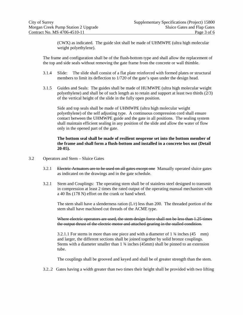
(CWX) as indicated. The guide slot shall be made of UHMWPE (ultra high molecular weight polyethylene).
The frame and configuration shall be of the flush-bottom type and shall allow the replacement of the top and side seals without removing the gate frame from the concrete or wall thimble. 3.1.4 Slide: The slide shall consist of a flat plate reinforced with formed plates or structural
members to limit its deflection to 1/720 of the gate’s span under the design head. 3.1.5 Guides and Seals: The guides shall be made of HUMWPE (ultra high molecular weight
polyethylene) and shall be of such length as to retain and support at least two thirds (2/3) of the vertical height of the slide in the fully open position.
Side and top seals shall be made of UHMWPE (ultra high molecular weight polyethylene) of the self adjusting type. A continuous compression cord shall ensure contact between the UHMWPE guide and the gate in all positions. The sealing system shall maintain efficient sealing in any position of the slide and allow the water of flow only in the opened part of the gate.
The bottom seal shall be made of resilient neoprene set into the bottom member of the frame and shall form a flush-bottom and installed in a concrete box out (Detail 20-05).
3.2 Operators and Stem – Sluice Gates
3.2.1 Electric Actuators are to be used on all gates except one Manually operated sluice gates as indicated on the drawings and in the gate schedule.
3.2.1 Stem and Couplings: The operating stem shall be of stainless steel designed to transmit
in compression at least 2 times the rated output of the operating manual mechanism with a 40 lbs (178 N) effort on the crank or hand wheel.
The stem shall have a slenderness ration (L/r) less than 200. The threaded portion of the stem shall have machined cut threads of the ACME type.
Where electric operators are used, the stem design force shall not be less than 1.25 times the output thrust of the electric motor and attached gearing in the stalled condition.
3.2.1.1 For stems in more than one piece and with a diameter of 1 ¾ inches (45 mm) and larger, the different sections shall be joined together by solid bronze couplings. Stems with a diameter smaller than 1 ¾ inches (45mm) shall be pinned to an extension tube.
The couplings shall be grooved and keyed and shall be of greater strength than the stem.
3.2..2 Gates having a width greater than two times their height shall be provided with two lifting

City of Surrey Supplementary Specifications (Project) 15800 Morgan Creek Pump Station 2 Upgrade Sluice Gates and Flap Gates Contract No. MS 4706-4510-11 Page 4 of 6
mechanisms connected by a tandem shaft. 3.2.3 Stem Guides: Stem guides shall be fabricated from type 304L stainless steel. The guide
shall be equipped with an UHMWPE bushing. Guides shall be adjustable and spaced in accordance with the manufacturer’s recommendation. The L/ratio shall not be greater than 200.
3.2.4 Stem Cover: Rising stem gates shall be provided with a clear polycarbonate stem cover.
The stem cover shall have a cap and condensation vents and a clear mylar position indicating tape. The tape shall be field applied to the stem cover after the gate has been installed and positioned.
3.2.5 Lifting Mechanism: Manual operators of the types listed in the schedule shall be
provided by the gate manufacturer. The gate shall be operated from above the concrete floor slab using a 50 mm square nut. A tee handle shall be provided for gate operation.
All bearings and gears shall be totally enclosed in a weather tight housing. The pinion shaft of crank-operated mechanisms shall be constructed of stainless steel and supported by roller or needle bearings.
Each manual operator shall be designed to operate the gate under the maximum specified seating and unseating heads by using a maximum effort of 40 lbs (178 N) on the crank or handwheel, and shall be able to withstand, without damage, an effort of 80 lbs (356 N).
The crank shall be removable and fitted with a corrosion-resistant rotating handle. The maximum crank radius shall be 15 inches (381 mm) and the maximum handwheel diameter shall be 24 inches (610 mm).
3.2.5 Yoke: Self-contained gates shall be provided with a yoke made of structural members or
formed plates. The maximum deflection of the yoke shall be 1/360 of the gate’s span. 4.0 MATERIALS
Part Material
Frame, yoke, stem guides, slide, stem extension
Stainless Steel ASTM A-240 Type 304L
Side seals, stem guide liner
Ultra high molecular weight polyethylene (UHMWPE) ASTM D-4020
Compression cord Nitrile ASTM D-2000 M6BG 708, A14, B14, E014, E034
Bottom Seal Neoprene ASTM D-2000 Grade 2 BC 510
City of Surrey Supplementary Specifications (Project) 15800 Morgan Creek Pump Station 2 Upgrade Sluice Gates and Flap Gates Contract No. MS 4706-4510-11 Page 5 of 6
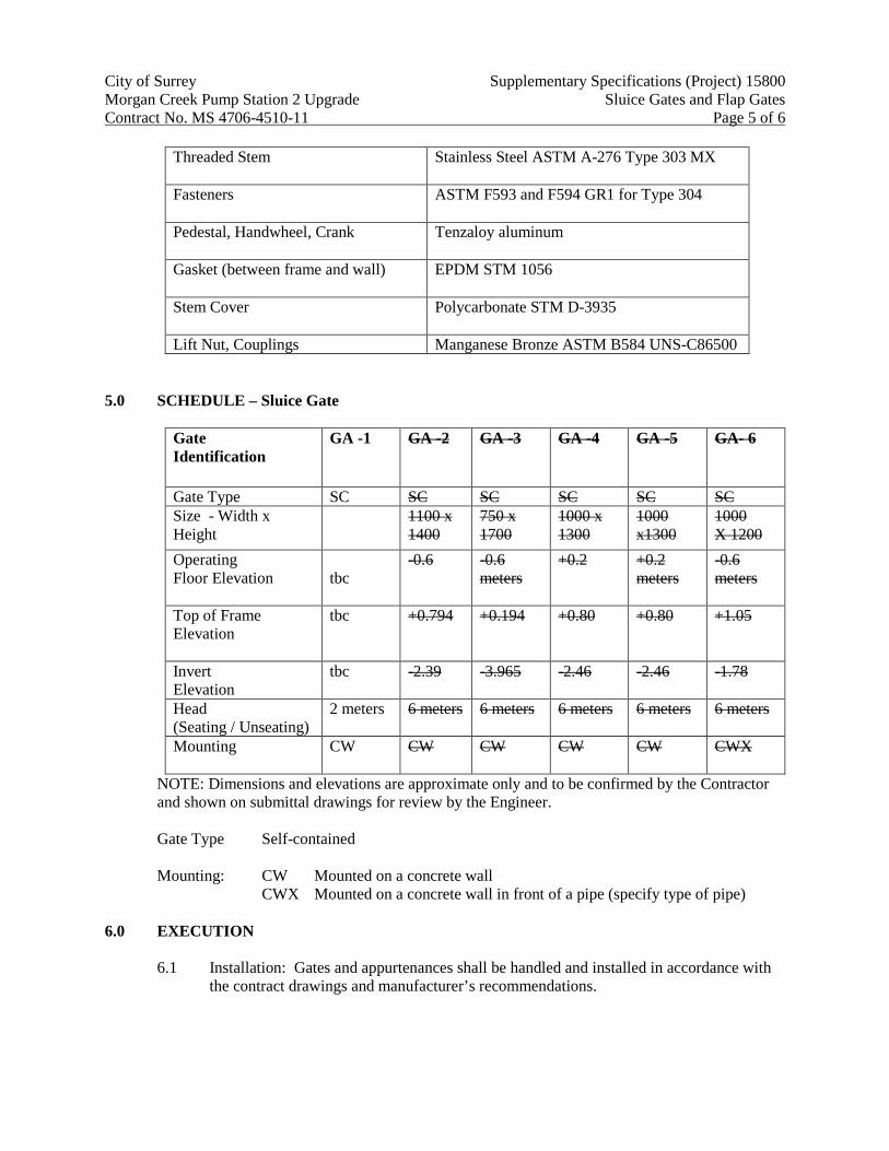
Threaded Stem Stainless Steel ASTM A-276 Type 303 MX
Fasteners ASTM F593 and F594 GR1 for Type 304
Pedestal, Handwheel, Crank Tenzaloy aluminum
Gasket (between frame and wall) EPDM STM 1056
Stem Cover
Polycarbonate STM D-3935
Lift Nut, Couplings Manganese Bronze ASTM B584 UNS-C86500 5.0 SCHEDULE – Sluice Gate
Gate Identification
GA -1 GA -2 GA -3 GA -4 GA -5 GA- 6
Gate Type SC SC SC SC SC SC Size - Width x Height
1100 x 1400
750 x 1700
1000 x 1300
1000 x1300
1000 X 1200
Operating Floor Elevation
tbc
-0.6 -0.6 meters
+0.2 +0.2 meters
-0.6 meters
Top of Frame Elevation
tbc +0.794 +0.194 +0.80 +0.80 +1.05
Invert Elevation
tbc -2.39 -3.965 -2.46 -2.46 -1.78
Head (Seating / Unseating)
2 meters 6 meters 6 meters 6 meters 6 meters 6 meters
Mounting
CW CW CW CW CW CWX
NOTE: Dimensions and elevations are approximate only and to be confirmed by the Contractor and shown on submittal drawings for review by the Engineer.
Gate Type Self-contained Mounting: CW Mounted on a concrete wall
CWX Mounted on a concrete wall in front of a pipe (specify type of pipe)
6.0 EXECUTION
6.1 Installation: Gates and appurtenances shall be handled and installed in accordance with the contract drawings and manufacturer’s recommendations.

City of Surrey Supplementary Specifications (Project) 15800 Morgan Creek Pump Station 2 Upgrade Sluice Gates and Flap Gates Contract No. MS 4706-4510-11 Page 6 of 6
6.2 Field Tests 6.2.1 Following the completion of each gate installation the gates shall be operated through at
least two complete open/close cycles. For electrically operated gates, limit switches shall be adjusted following the manufacturer’s instructions.
6.2.2 Gates should be checked for leakage by the contractor (refer to the “Performance” section
for approval criteria).