ms8609a - welcome to livingston, the leading test & …€¦ · · 2012-01-20the ms8609a is a...
TRANSCRIPT

MS8609ADigital Mobile Radio Transmitter Tester9 kHz to 13.2 GHz
For Evaluation ofEach MobileCommunication

2
Measures Wide-Band Signalsup to 20 MHzThe MS8609A is a transmitter tester equipped with an internal
spectrum analyzer, a modulation analyzer and a power meter.
One tester covers the development, manufacturing of base stations,
mobile stations to construction, maintenance of base stations.
The spectrum analyzer has resolution bandwidths up to
20 MHz, meaning that it can readily support measurement of
wide-band signal.
The modulation analyzer realizes all Vector Signal Analysis
(VSA) functions through high-speed DSP. The power sensor can
perform highly accurate power measurements of ±0.4 dB by
using an amorphous power sensor.
Up to three dedicated measurement software options (such as
W-CDMA and GSM/EDGE) can be installed simultaneously. Input
signals can be selected from either RF or I/Q inputs. For I/Q
signals, balanced or unbalanced input can also be selected.
It is equipped with GPIB, RS-232C and 10 Base-T (optional)
interfaces for remote measurement. High-speed GPIB data
transmission of 120 kbyte/s enables high-speed measurement on
the manufacturing line. The monitor uses an easy-to-see 6.5 type
TFT color LCD.
Base-T (optional)Base-T (optional)Base-T (optional)Base-T (optional)Base-T (optional)Base-T (optional)Base-T (optional)Base-T (optional)Base-T (optional)Base-T (optional)Base-T (optional)Base-T (optional)Base-T (optional)Base-T (optional)Base-T (optional)Base-T (optional)Base-T (optional)

3
Spectrum Analyzer FunctionsFrequency Frequency range: 9 kHz to 13.2 GHzResolution bandwidth: 300 Hz to 3 MHz, 5 MHz, 10 MHz, 20 MHz (to 3 GHz)Frequency span: Zero, 1 kHz to 13.2 GHzSpan accuracy: ±1%Reference frequency accuracy: ±2 x 10⁻⁸/day, ±5 x 10⁻¹⁰/day (option), ±1 x 10⁻¹⁰/year (option)Level Maximum input level: +20 dBm Input attenuator: 0 to 62 dB (2 dB steps)1 dB gain compression: +3 dBm (≥500 MHz)Two tone 3rd order distortion: ≤–85 dBc (0.1 to 3.2 GHz)Sweep Frequency span: 10 ms to 1000 sTime span: 1 µs to 1000 sRefresh rate: >20 times/sOthers Detection mode: Normal, positive, negative, sample, average, RMS (option)Measurement functions: Frequency counter, noise power, C/N, ACP, OBW, etc.GPIB transmission speed: 120 kbyte/s

4
MS8609A Panel Layout
i o
!0
q w e r t
y
u
!2!1 !3 !4
5
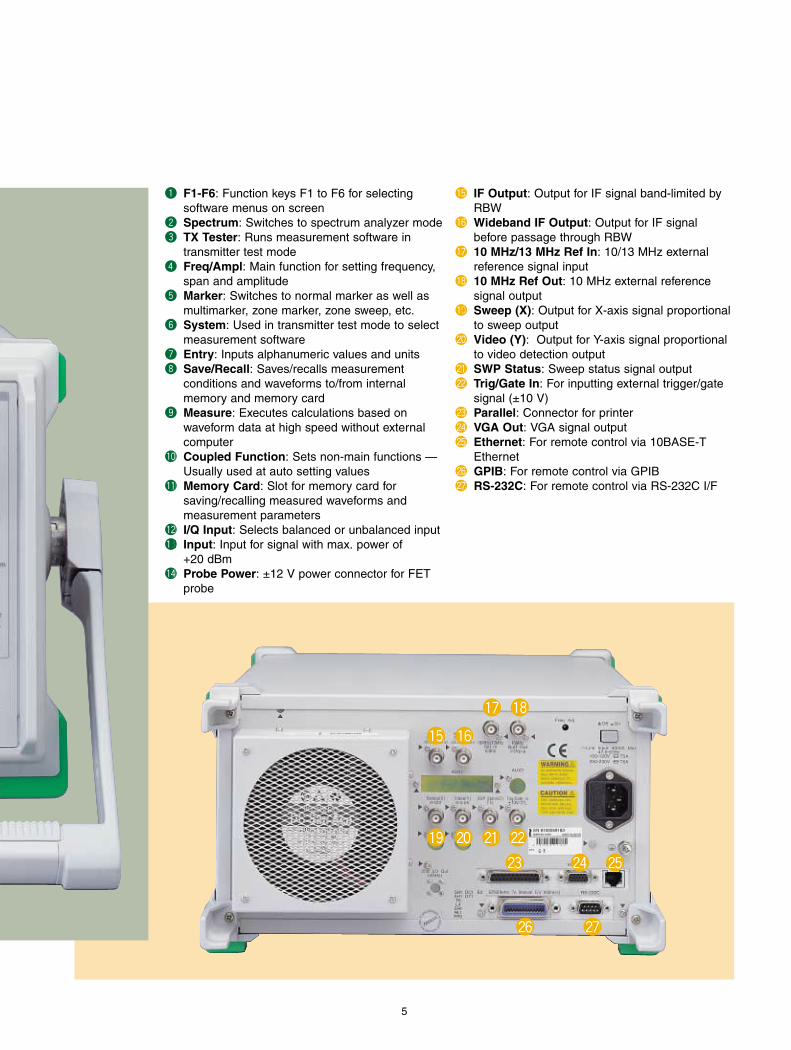
q F1-F6: Function keys F1 to F6 for selecting software menus on screen
w Spectrum: Switches to spectrum analyzer modee TX Tester: Runs measurement software in
transmitter test moder Freq/Ampl: Main function for setting frequency,
span and amplitudet Marker: Switches to normal marker as well as
multimarker, zone marker, zone sweep, etc. y System: Used in transmitter test mode to select
measurement softwareu Entry: Inputs alphanumeric values and unitsi Save/Recall: Saves/recalls measurement
conditions and waveforms to/from internal memory and memory card
o Measure: Executes calculations based on waveform data at high speed without externalcomputer
!0 Coupled Function: Sets non-main functions —Usually used at auto setting values
!1 Memory Card: Slot for memory card forsaving/recalling measured waveforms and measurement parameters
!2 I/Q Input: Selects balanced or unbalanced input!33333 Input: Input for signal with max. power of
+20 dBm!4 Probe Power: ±12 V power connector for FET
probe
!5 IF Output: Output for IF signal band-limited byRBW
!6 Wideband IF Output: Output for IF signalbefore passage through RBW
!7 10 MHz/13 MHz Ref In: 10/13 MHz external reference signal input
!8 10 MHz Ref Out: 10 MHz external reference signal output
!90 Sweep (X): Output for X-axis signal proportionalto sweep output
@0 Video (Y): Output for Y-axis signal proportionalto video detection output
@1 SWP Status: Sweep status signal output@2 Trig/Gate In: For inputting external trigger/gate
signal (±10 V)@3 Parallel: Connector for printer@4 VGA Out: VGA signal output@5 Ethernet: For remote control via 10BASE-T
Ethernet@6 GPIB: For remote control via GPIB@7 RS-232C: For remote control via RS-232C I/F
!5 !6
!7 !8
!9 @0 @1 @2
@3 @4 @5
@6 @7
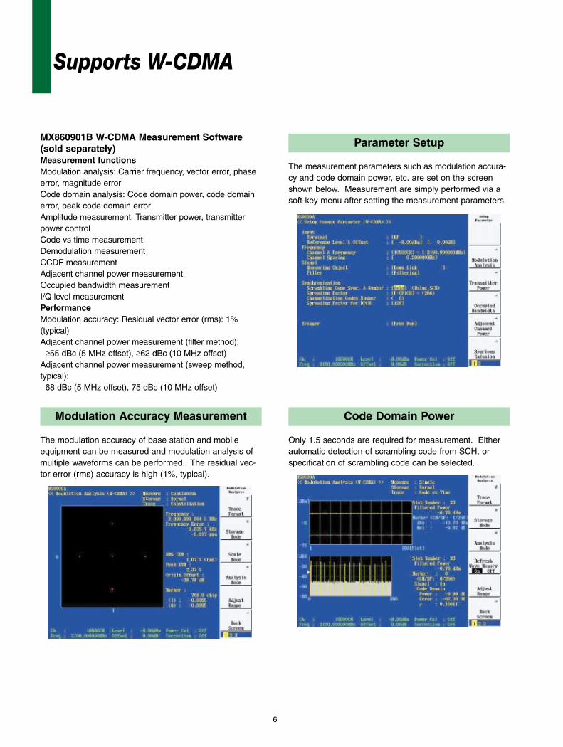
Parameter Setup
The measurement parameters such as modulation accura-cy and code domain power, etc. are set on the screenshown below. Measurement are simply performed via asoft-key menu after setting the measurement parameters.
Modulation Accuracy Measurement
The modulation accuracy of base station and mobileequipment can be measured and modulation analysis ofmultiple waveforms can be performed. The residual vec-tor error (rms) accuracy is high (1%, typical).
Code Domain Power
Only 1.5 seconds are required for measurement. Eitherautomatic detection of scrambling code from SCH, orspecification of scrambling code can be selected.
Supports W-CDMA
6
MX860901B W-CDMA Measurement Software(sold separately)Measurement functionsModulation analysis: Carrier frequency, vector error, phaseerror, magnitude errorCode domain analysis: Code domain power, code domainerror, peak code domain errorAmplitude measurement: Transmitter power, transmitterpower controlCode vs time measurementDemodulation measurementCCDF measurementAdjacent channel power measurementOccupied bandwidth measurementI/Q level measurementPerformanceModulation accuracy: Residual vector error (rms): 1% (typical)Adjacent channel power measurement (filter method):
≥55 dBc (5 MHz offset), ≥62 dBc (10 MHz offset)Adjacent channel power measurement (sweep method, typical):
68 dBc (5 MHz offset), 75 dBc (10 MHz offset)

7
I/Q Level Measurement
Measures and displays each I and Q input voltage (rms,p-p value). dBmV or mV units are selectable.
Demodulation Data Monitoring Function
After de-spreading, up to 10 frames of demodulation datacan be evaluated.
Power Meter Function
The built-in power meter uses the amorphous power sen-sor and the measurement accuracy is very high (±0.4 dB).
CCDF Measurement
It enables distribution display or cumulative distribution dis-play of the power difference between instantaneous powerand average power. Max. 20 MHz of filter bandwidth isable to perform multi-carrier measurement.

8
Supports GSM, EDGE
Parameter Setup
The measurement parameters such as GMSK modulation ofGSM and 8PSK modulation of EDGE are set on the screenshown below. Measurement are simply performed via asoft-key menu after setting the measurement parameters.
MX860902A GSM Measurement Software (sold separately)Measurement functionsModulation analysis:
Carrier frequency, phase error (RMS, peak),magnitude error
*Filter complies with ETSI standards (for EDGE modula-tion analysis) selectable
Amplitude measurement: transmitter powerMeasurement for rise/fall edge characteristics of the antennapowerOutput RF spectrum measurementSpurious measurementI/Q level measurementPerformanceModulation accuracyResidual phase error: <0.5° (rms) [GMSK modulation]Residual EVM: <1.0% (rms) [8PSK modulation]Transmitter power: ±0.4 dB
Transmitter Power Measurement
The screen displays the amplitude waveforms with hori-zontal axis a symbol, vertical axis a level and the templatesimultaneously.
Modulation Accuracy Measurement
The modulation accuracy is high. (The residual phaseerror of GMSK modulation: rms, < 0.5° and residual EVMof 8PSK modulation: rms, < 1.0%)

9
Output RF Spectrum Measurement
The output RF spectrum measurement can be performedat high speed and simply.
EDGE Constellation Display
The following screen represents constellation displaythrough the filter of the EDGE constellation display of theGSM standard.
Spurious Measurement
Spurious measurement has three kinds of method:Sweep, Search, and Spot. These can be selecteddepending on the usage.
The following screen represents constellation display ofthe 8PSK modulation through Nyquist filter and Gaussianinverse correction filter.

10
Parameter Setup
A setup screen is provided for the entry of required parame-ters for modulation accuracy and code domain power mea-surements in cdmaOne or CDMA2000 1xRTT analysis.Measurement can be performed after parameter setup.
MX860903A cdma Measurement Software (sold separately)Measurement functionsModulation analysis:
Carrier frequency, vector error, phase error, magnitudeerror
Code domain analysis: Code domain power, code domain timing offset, codedomain phase offset
Amplitude measurement: Transmission powerSpurious close to the carrier measurementSpurious measurementOccupied bandwidth measurementI/Q level measurement
BTS Code Domain Analysis
Only 2 seconds are required for code domain analysis of1xRTT signals, RC* 1 through RC5 can be measured.Spreading factor of each code is automatically detectedand displayed on the screen. *Radio Configuration
Modulation Accuracy Measurement
Frequency error, modulation accuracy and code domainanalysis are performed and then results are displayed onthe screen. The measurement accuracy is 1% (typicalvalue) of residual vector error (rms).
Supporting cdmaOne and CDMA2000 1xRTT

11
MS Code Domain Analysis
Perform code domain analysis of 1xRTT signals in RC3and RC4 in only 2 seconds. Code domains of I/Q phaseare displayed on the screen.
Spurious Close to the Carrier Measurement
Spurious close to the carrier is measured using the spec-trum analyzer function. The PASS/FAIL result of a tem-plate judgement is displayed on the screen.
Transmission Power Measurement
When transmission power is measured both the value andsignal waveform are displayed on the screen. High accu-racy power measurements are achieved using the built-inpower meter function.
Spurious Measurement
A frequency table can be set up in spurious measurementto provide a PASS/FAIL measurement result. Fifteen dif-ferent frequencies and their limit values can be entered.

Supports PDC, PHS and NADC––– Evaluation of π/4DQPSK transmission systems with single cabinet
12
Parameter Setting
Analysis of PDC, PHS and NADC (IS-136) systems requiressetting of parameters for important measurement such asmodulation accuracy at this screen. Changing the symbolrate also permits analysis of systems other than PDC, PHSand NADC.
MX860905A π/4DQPSK Measurement Software(sold separately)Measurement functionsModulation analysis:
Carrier frequency, vector error, phase error, magnitudeerror
Amplitude measurement: Transmitter power, carrier-off leakage power, rise/fall char-acteristics
Adjacent channel power measurementSpurious measurementOccupied bandwidth measurementI/Q level measurementGeneral purpose measurement
Transmitter Power Measurement
This screen displays the transmitter power and waveform.The power value is calibrated by the built-in power meterto achieve even higher accuracy power measurement.
Modulation Accuracy Measurement
The constellation display is combined with the modulationaccuracy measurement results to monitor the residualvector error (rms) with a high accuracy of 0.5 % (PDC).

13
Transmission Timing Measurement
This screen displays the PHS send timing. In addition,when average measurement is selected, the send jitter isalso displayed.
Adjacent Channel Power Measurement
When measurement is performed using a spectrum ana-lyzer, the adjacent channel power is measured after pas-sage through a built-in filter (root Nyquist). A high-speedmeasurement method can also be selected.
Occupied Bandwidth Measurement
The occupied bandwidth is measured with a spectrumanalyzer or by FFT using DSP, and displayed.
Spurious Measurement
There are three methods: spot, sweep and search.Frequency and limit value can be set maximum 15 in thetables. The measurement results are displayed with alimit evaluation.
Specifications
• MS8609A
14
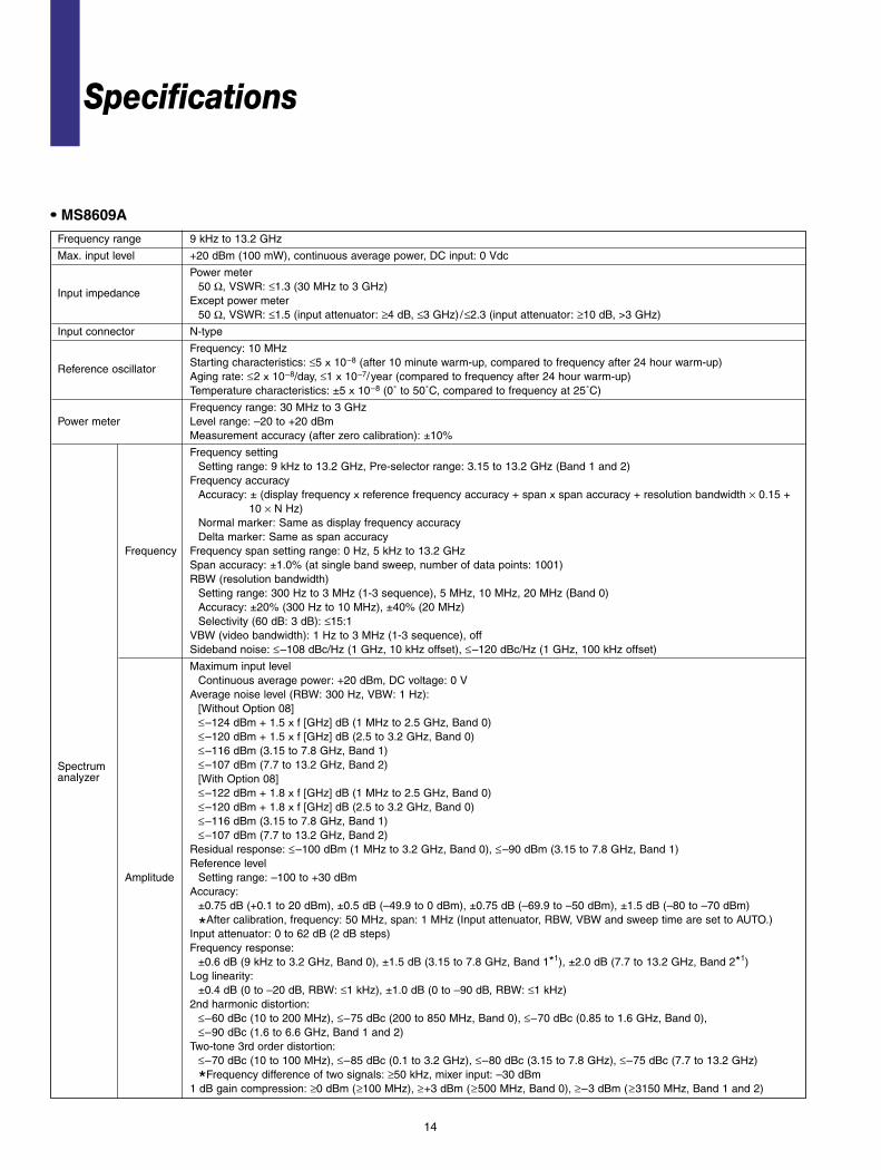
Frequency range 9 kHz to 13.2 GHz
Max. input level +20 dBm (100 mW), continuous average power, DC input: 0 Vdc
Power meter50 Ω, VSWR: ≤1.3 (30 MHz to 3 GHz)
Input impedanceExcept power meter
50 Ω, VSWR: ≤1.5 (input attenuator: ≥4 dB, ≤3 GHz) /≤2.3 (input attenuator: ≥10 dB, >3 GHz)
Input connector N-type
Frequency: 10 MHzStarting characteristics: ≤5 x 10⁻⁸ (after 10 minute warm-up, compared to frequency after 24 hour warm-up)
Reference oscillatorAging rate: ≤2 x 10⁻⁸/day, ≤1 x 10⁻⁷/year (compared to frequency after 24 hour warm-up)Temperature characteristics: ±5 x 10⁻⁸ (0˚ to 50˚C, compared to frequency at 25˚C)
Frequency range: 30 MHz to 3 GHzPower meter Level range: –20 to +20 dBm
Measurement accuracy (after zero calibration): ±10%
Frequency settingSetting range: 9 kHz to 13.2 GHz, Pre-selector range: 3.15 to 13.2 GHz (Band 1 and 2)
Frequency accuracyAccuracy: ± (display frequency x reference frequency accuracy + span x span accuracy + resolution bandwidth × 0.15 +
10 × N Hz)Normal marker: Same as display frequency accuracyDelta marker: Same as span accuracy
Frequency Frequency span setting range: 0 Hz, 5 kHz to 13.2 GHz Span accuracy: ±1.0% (at single band sweep, number of data points: 1001)RBW (resolution bandwidth)
Setting range: 300 Hz to 3 MHz (1-3 sequence), 5 MHz, 10 MHz, 20 MHz (Band 0)Accuracy: ±20% (300 Hz to 10 MHz), ±40% (20 MHz)Selectivity (60 dB: 3 dB): ≤15:1
VBW (video bandwidth): 1 Hz to 3 MHz (1-3 sequence), off Sideband noise: ≤–108 dBc/Hz (1 GHz, 10 kHz offset), ≤–120 dBc/Hz (1 GHz, 100 kHz offset)
Maximum input levelContinuous average power: +20 dBm, DC voltage: 0 V
Average noise level (RBW: 300 Hz, VBW: 1 Hz):[Without Option 08]≤–124 dBm + 1.5 x f [GHz] dB (1 MHz to 2.5 GHz, Band 0)≤–120 dBm + 1.5 x f [GHz] dB (2.5 to 3.2 GHz, Band 0)≤–116 dBm (3.15 to 7.8 GHz, Band 1)
Spectrum ≤–107 dBm (7.7 to 13.2 GHz, Band 2)analyzer [With Option 08]
≤–122 dBm + 1.8 x f [GHz] dB (1 MHz to 2.5 GHz, Band 0)≤–120 dBm + 1.8 x f [GHz] dB (2.5 to 3.2 GHz, Band 0)≤–116 dBm (3.15 to 7.8 GHz, Band 1)≤–107 dBm (7.7 to 13.2 GHz, Band 2)
Residual response: ≤–100 dBm (1 MHz to 3.2 GHz, Band 0), ≤–90 dBm (3.15 to 7.8 GHz, Band 1)Reference level
Amplitude Setting range: –100 to +30 dBm Accuracy:
±0.75 dB (+0.1 to 20 dBm), ±0.5 dB (–49.9 to 0 dBm), ±0.75 dB (–69.9 to –50 dBm), ±1.5 dB (–80 to –70 dBm)
*After calibration, frequency: 50 MHz, span: 1 MHz (Input attenuator, RBW, VBW and sweep time are set to AUTO.)Input attenuator: 0 to 62 dB (2 dB steps)Frequency response:
±0.6 dB (9 kHz to 3.2 GHz, Band 0), ±1.5 dB (3.15 to 7.8 GHz, Band 1*1), ±2.0 dB (7.7 to 13.2 GHz, Band 2*1)Log linearity:
±0.4 dB (0 to –20 dB, RBW: ≤1 kHz), ±1.0 dB (0 to –90 dB, RBW: ≤1 kHz)2nd harmonic distortion:
≤–60 dBc (10 to 200 MHz), ≤–75 dBc (200 to 850 MHz, Band 0), ≤–70 dBc (0.85 to 1.6 GHz, Band 0), ≤–90 dBc (1.6 to 6.6 GHz, Band 1 and 2)
Two-tone 3rd order distortion:≤–70 dBc (10 to 100 MHz), ≤–85 dBc (0.1 to 3.2 GHz), ≤–80 dBc (3.15 to 7.8 GHz), ≤–75 dBc (7.7 to 13.2 GHz)
*Frequency difference of two signals: ≥50 kHz, mixer input: –30 dBm1 dB gain compression: ≥0 dBm (≥100 MHz), ≥+3 dBm (≥500 MHz, Band 0), ≥–3 dBm (≥3150 MHz, Band 1 and 2)
15
*1: Reference frequency: 50 MHz, input attenuator: 10 dB, 18˚ to 28˚C
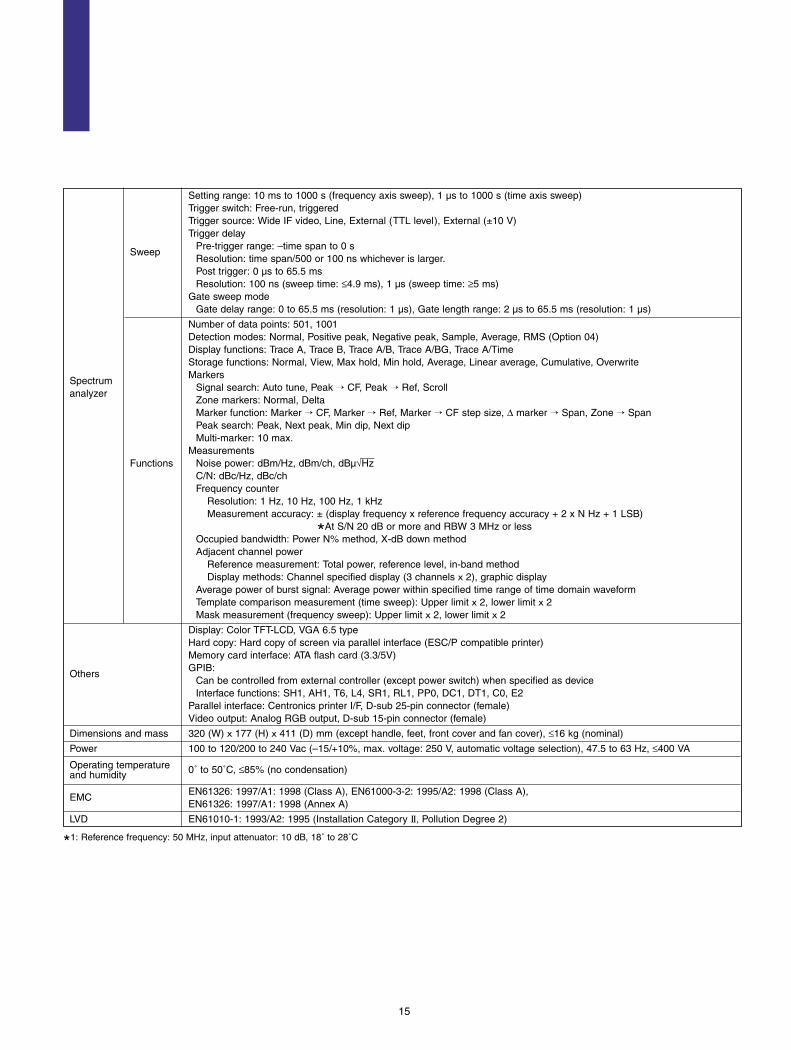
Setting range: 10 ms to 1000 s (frequency axis sweep), 1 µs to 1000 s (time axis sweep)Trigger switch: Free-run, triggeredTrigger source: Wide IF video, Line, External (TTL level), External (±10 V)Trigger delay
Pre-trigger range: –time span to 0 sSweep
Resolution: time span/500 or 100 ns whichever is larger. Post trigger: 0 µs to 65.5 msResolution: 100 ns (sweep time: ≤4.9 ms), 1 µs (sweep time: ≥5 ms)
Gate sweep modeGate delay range: 0 to 65.5 ms (resolution: 1 µs), Gate length range: 2 µs to 65.5 ms (resolution: 1 µs)
Number of data points: 501, 1001Detection modes: Normal, Positive peak, Negative peak, Sample, Average, RMS (Option 04)Display functions: Trace A, Trace B, Trace A/B, Trace A/BG, Trace A/TimeStorage functions: Normal, View, Max hold, Min hold, Average, Linear average, Cumulative, OverwriteMarkers
SpectrumSignal search: Auto tune, Peak → CF, Peak → Ref, Scroll
analyzerZone markers: Normal, DeltaMarker function: Marker → CF, Marker → Ref, Marker → CF step size, ∆ marker → Span, Zone → Span Peak search: Peak, Next peak, Min dip, Next dipMulti-marker: 10 max.
MeasurementsFunctions Noise power: dBm/Hz, dBm/ch, dBµ√Hz
C/N: dBc/Hz, dBc/chFrequency counter
Resolution: 1 Hz, 10 Hz, 100 Hz, 1 kHzMeasurement accuracy: ± (display frequency x reference frequency accuracy + 2 x N Hz + 1 LSB)
*At S/N 20 dB or more and RBW 3 MHz or lessOccupied bandwidth: Power N% method, X-dB down methodAdjacent channel power
Reference measurement: Total power, reference level, in-band methodDisplay methods: Channel specified display (3 channels x 2), graphic display
Average power of burst signal: Average power within specified time range of time domain waveformTemplate comparison measurement (time sweep): Upper limit x 2, lower limit x 2Mask measurement (frequency sweep): Upper limit x 2, lower limit x 2
Display: Color TFT-LCD, VGA 6.5 typeHard copy: Hard copy of screen via parallel interface (ESC/P compatible printer)Memory card interface: ATA flash card (3.3/5V)GPIB:
OthersCan be controlled from external controller (except power switch) when specified as deviceInterface functions: SH1, AH1, T6, L4, SR1, RL1, PP0, DC1, DT1, C0, E2
Parallel interface: Centronics printer I/F, D-sub 25-pin connector (female)Video output: Analog RGB output, D-sub 15-pin connector (female)
Dimensions and mass 320 (W) x 177 (H) x 411 (D) mm (except handle, feet, front cover and fan cover), ≤16 kg (nominal)
Power 100 to 120/200 to 240 Vac (–15/+10%, max. voltage: 250 V, automatic voltage selection), 47.5 to 63 Hz, ≤400 VA
Operating temperature and humidity 0˚ to 50˚C, ≤85% (no condensation)
EN61326: 1997/A1: 1998 (Class A), EN61000-3-2: 1995/A2: 1998 (Class A),EMC
EN61326: 1997/A1: 1998 (Annex A)
LVD EN61010-1: 1993/A2: 1995 (Installation Category ΙΙ, Pollution Degree 2)

• MX860901B W-CDMA Measurement SoftwareGuaranteed specifications after Adjust Range and Power Calibration keys pressed
16
Frequency range: 50 MHz to 3 GHz, 50 MHz to 2.3 GHz (Option 08)Input level: –60 to +20 dBm (average power, pre-amplifier: off), –80 to +10 dBm (average power, pre-amplifier: on*1)Carrier frequency accuracy: ±(reference oscillator accuracy + 10 Hz)
*Input level: ≥–30 dBm (pre-amplifier: off), ≥–40 dBm (pre-amplifier: on*1),1 code channel Modulation accuracy (residual vector error): <2% (rms)
Modulation/frequency
*Input level: ≥–30 dBm (pre-amplifier: off), ≥–40 dBm (pre-amplifier: on*1), 1 code channelmeasurement
Origin offset accuracy: ±0.5 dB
*Input level: ≥–30 dBm (pre-amplifier: off), ≥–40 dBm (pre-amplifier: on*1), 1 code channel, relative to signal with origin offset of –30 dBc
Waveform display (for one-channel to multi-channel) Constellation, eye pattern, vector error vs. chip, phase error vs. chip, amplitude error vs. chip, code vs. slot
Frequency range: 50 MHz to 3 GHz, 50 MHz to 2.3 GHz (Option 08)Input level: –60 to +20 dBm (average power, pre-amplifier: off), –80 to +10 dBm (average power, pre-amplifier: on*1)Code domain power accuracy:
±0.1 dB (code power: ≥–10 dBc), ±0.3 dB (code power: ≥–25 dBc)
*Input level: ≥–10 dBm (pre-amplifier: off), ≥–20 dBm (pre-amplifier: on*1)Code domain error
Residual error: <–50 dB Accuracy: ±0.5 dB (error: relative to signal with origin offset of –30 dBc)
Code domain analysis *Input level: ≥–10 dBm (pre-amplifier: off); ≥–20 dBm (pre-amplifier: on*1), spread factor: 512 (down-link)/256 (up-link) Display
Function: Code domain power, code domain errorSpread factor: 4 to 256 (up-link)/4 to 512 (down-link), spread factor auto detection function, SCH level measurement
function, I/Q separately at up-linkCode vs. slot measurement:
Measures code domain power per slot of specified code channel for Max.150 slots. (Supporting compressed mode in downlink)
Frequency range: 50 MHz to 3 GHz, 50 MHz to 2.3 GHz (Option 08)Input level:
–60 to +20 dBm (average power, pre-amplifier: off), –80 to +10 dBm (average power, pre-amplifier: on*1)Transmitter power measurement
Measurement range: –20 to +20 dBm (average power, pre-amplifier: off), –20 to +10 dBm (average power, pre-amplifier: on*1) *Auto calibrated at internal power meter
Amplitude measurement Accuracy: ±0.4% Power measurement linearity: ±0.2 dB (0 to –40 dB)
*Input level: ≥–10 dBm (pre-amplifier: off); ≥–20 dBm (pre-amplifier: on*1), after the range adjusted, with the reference level setting unchanged
Filter selection function: Power measurement through RRC (α= 0.22) filterTransmitter power control measurement function: Relative power display per slot for Max 150 slots, NO/GO evaluationRACH measurement function: Measures the time difference between preamble RACH signal and message RACH signal.
Frequency range: 50 MHz to 3 GHzInput level:
Occupied bandwidth –60 to +20 dBm (average power, pre-amplifier: off), –80 to +10 dBm (average power, pre-amplifier: on*1)measurement Measurement method
Sweep method: Displays result after signal measured with sweep spectrum analyzerFFT method: Displays result after FFT
17
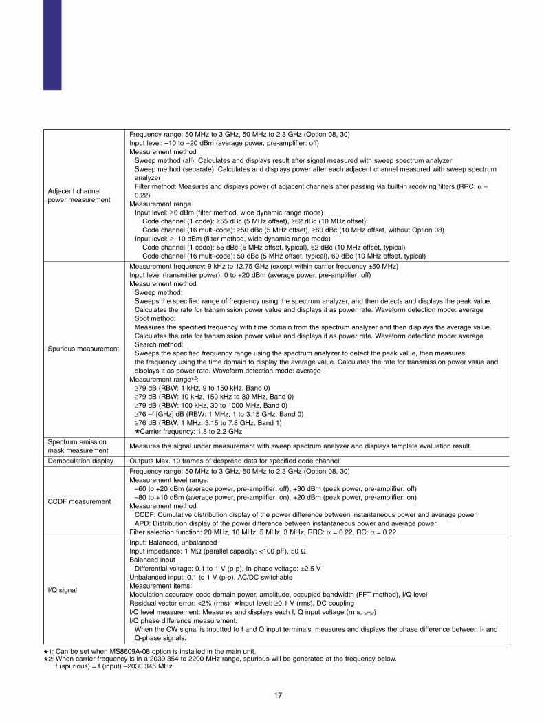
Frequency range: 50 MHz to 3 GHz, 50 MHz to 2.3 GHz (Option 08, 30)Input level: –10 to +20 dBm (average power, pre-amplifier: off)Measurement method
Sweep method (all): Calculates and displays result after signal measured with sweep spectrum analyzer Sweep method (separate): Calculates and displays power after each adjacent channel measured with sweep spectrum analyzer
Adjacent channelFilter method: Measures and displays power of adjacent channels after passing via built-in receiving filters (RRC: α =
power measurement0.22)
Measurement rangeInput level: ≥0 dBm (filter method, wide dynamic range mode)
Code channel (1 code): ≥55 dBc (5 MHz offset), ≥62 dBc (10 MHz offset)Code channel (16 multi-code): ≥50 dBc (5 MHz offset), ≥60 dBc (10 MHz offset, without Option 08)
Input level: ≥–10 dBm (filter method, wide dynamic range mode)Code channel (1 code): 55 dBc (5 MHz offset, typical), 62 dBc (10 MHz offset, typical) Code channel (16 multi-code): 50 dBc (5 MHz offset, typical), 60 dBc (10 MHz offset, typical)
Measurement frequency: 9 kHz to 12.75 GHz (except within carrier frequency ±50 MHz)Input level (transmitter power): 0 to +20 dBm (average power, pre-amplifier: off)Measurement method
Sweep method: Sweeps the specified range of frequency using the spectrum analyzer, and then detects and displays the peak value. Calculates the rate for transmission power value and displays it as power rate. Waveform detection mode: averageSpot method: Measures the specified frequency with time domain from the spectrum analyzer and then displays the average value. Calculates the rate for transmission power value and displays it as power rate. Waveform detection mode: average Search method:
Spurious measurementSweeps the specified frequency range using the spectrum analyzer to detect the peak value, then measures the frequency using the time domain to display the average value. Calculates the rate for transmission power value and displays it as power rate. Waveform detection mode: average
Measurement range*2: ≥79 dB (RBW: 1 kHz, 9 to 150 kHz, Band 0)≥79 dB (RBW: 10 kHz, 150 kHz to 30 MHz, Band 0)≥79 dB (RBW: 100 kHz, 30 to 1000 MHz, Band 0)≥76 –f [GHz] dB (RBW: 1 MHz, 1 to 3.15 GHz, Band 0)≥76 dB (RBW: 1 MHz, 3.15 to 7.8 GHz, Band 1)
*Carrier frequency: 1.8 to 2.2 GHz
Spectrum emission mask measurement
Measures the signal under measurement with sweep spectrum analyzer and displays template evaluation result.
Demodulation display Outputs Max. 10 frames of despread data for specified code channel.
Frequency range: 50 MHz to 3 GHz, 50 MHz to 2.3 GHz (Option 08, 30)Measurement level range:
–60 to +20 dBm (average power, pre-amplifier: off), +30 dBm (peak power, pre-amplifier: off)–80 to +10 dBm (average power, pre-amplifier: on), +20 dBm (peak power, pre-amplifier: on)
CCDF measurementMeasurement method
CCDF: Cumulative distribution display of the power difference between instantaneous power and average power.APD: Distribution display of the power difference between instantaneous power and average power.
Filter selection function: 20 MHz, 10 MHz, 5 MHz, 3 MHz, RRC: α = 0.22, RC: α = 0.22
Input: Balanced, unbalanced Input impedance: 1 MΩ (parallel capacity: <100 pF), 50 ΩBalanced input
Differential voltage: 0.1 to 1 V (p-p), In-phase voltage: ±2.5 VUnbalanced input: 0.1 to 1 V (p-p), AC/DC switchable Measurement items:
I/Q signalModulation accuracy, code domain power, amplitude, occupied bandwidth (FFT method), I/Q level Residual vector error: <2% (rms) *Input level: ≥0.1 V (rms), DC couplingI/Q level measurement: Measures and displays each I, Q input voltage (rms, p-p) I/Q phase difference measurement:
When the CW signal is inputted to I and Q input terminals, measures and displays the phase difference between I- and Q-phase signals.
*1: Can be set when MS8609A-08 option is installed in the main unit.
*2: When carrier frequency is in a 2030.354 to 2200 MHz range, spurious will be generated at the frequency below. f (spurious) = f (input) –2030.345 MHz

18
Frequency range: 50 MHz to 2.7 GHz Input level:
–40 to +20 dBm (burst average power, pre-amplifier: off), –60 to +10 dBm (burst average power, pre-amplifier: on*1)Carrier frequency accuracy:
±(reference oscillator accuracy + 10 Hz) Modulation/frequency *Input level (burst average power): ≥–30 dBm (pre-amplifier: off), ≥–40 dBm (pre-amplifier: on*1) measurement Residual phase error (GMSK modulation):
<0.5 deg (rms), <2.0 deg (peak)
*Input level (burst average power): ≥–30 dBm (pre-amplifier: off), ≥–40 dBm (pre-amplifier: on*1)Residual EVM (8PSK modulation): <1% (rms) Waveform display:
Trellis (GMSK modulation), eye pattern, EVM vs. bit (8PSK modulation), phase vs. bit, amplitude vs. bit, I/Q diagram
Frequency range: 50 MHz to 2.7 GHzInput level:
–40 to +20 dBm (burst average power, pre-amplifier: off), –60 to +10 dBm (burst average power, pre-amplifier: on*1)Transmitter power measurement (auto calibrated at internal power meter)
Measurement range: –10 to +20 dBm (burst average power), –10 to +10 dBm (burst average power, pre-amplifier: on*1) Accuracy: ±0.4 dB
Power measurement linearity: ±0.2 dB (0 to –30 dBm) *Input level (burst average power): ≥–10 dBm (pre-amplifier: off); ≥–20 dBm (pre-amplifier:on*1), without changing the reference level setting after range optimization
Amplitude measurement Carrier-off power measurement range Input level (burst average power): ≥–10 dBm (pre-amplifier: off), ≥–20 dBm (pre-amplifier: on*1) Normal mode: ≥60 dB (compared with burst average power)Wide dynamic range mode: ≥80 dB (compared with 10 mW of burst average power)
*Measurement limit is decided by average nose level (≤–70 dBm, 50 MHz to 2.7 GHz).Rise/fall characteristics:
Display rising/falling edges while synchronizing to modulation data of signal data to be measured. Standard line display possible (measured by 1 MHz bandwidth). NO/GO judgment function
Frequency range: 100 MHz to 2.7 GHzInput level:
Output RF spectrum –10 to +20 dBm (burst average power, pre-amplifier: off), –20 to +10 dBm (burst average power, pre-amplifier: on*1)measurement Modulation portion measurement range: ≥60 dB (≥200 kHz offset), ≥68 dB (≥250 kHz offset)
*CW signal, RBW: 30 kHz (<1.8 MHz offset), RBW: 100 kHz (≤1.8 MHz offset) Transient portion measurement range: ≥63 dB (CW, ≥400 kHz offset)
Measurement frequency: 100 kHz to 12.75 GHz (except within carrier frequency ±50 MHz)Input level (transmitter power): 0 to +20 dBm (burst average power, pre-amplifier: off)Measurement method
Sweep method: Sweeps the specified range of frequency using the spectrum analyzer, and then detects and displays the peak value. Calculates the rate for transmission power value and displays it as power rate. Waveform detection mode: averageSpot method: Measures the specified frequency with time domain from the spectrum analyzer and then displays the average value. Calculates the rate for transmission power value and displays it as power rate. Waveform detection mode: average
Spurious measurement Search method: Sweeps the specified frequency range using the spectrum analyzer to detect the peak value, then measures the frequencyusing the time domain to display the average value. Calculates the rate for transmission power value and displays it as power rate. Waveform detection mode: average
Measurement range: ≥72 dB (RBW: 10 kHz, 100 kHz to 50 MHz, Band 0)≥72 dB (RBW: 100 kHz, 50 to 500 MHz, Band 0)≥66 –f [GHz] dB (RBW: 3 MHz, 0.5 to 3.15 GHz, Band 0, except harmonic frequency)≥66 dB (RBW: 3 MHz, 3.15 to 7.8 GHz, Band 1)
*Carrier frequency: 0.8 to 1 GHz, 1.8 to 2 GHz
• MX860902A GSM Measurement SoftwareGuaranteed specifications after Adjust Range and Power Calibration keys pressed

19
Input: Balanced, unbalanced Input impedance: 1 MΩ (parallel capacity: <100 pF), 50 ΩBalanced input
Differential voltage: 0.1 to 1 V (p-p), In-phase voltage: ±2.5 VUnbalanced input: 0.1 to 1 V (p-p), AC/DC switchable Measurement items: Modulation accuracy, I/Q level
I/Q signal Modulation accuracyResidual phase error: <0.5 deg (rms), DC couplingResidual EVM: <1.0% (rms), DC coupling
*Input level: ≥0.1 V (rms), 18˚ to 28˚C I/Q level measurement: Measures and displays each I, Q input voltage (rms, p-p) I/Q phase difference measurement: When the CW signal is inputted to I and Q input terminals, measures and displays the phase difference between I- and Q-phase signals.
*1: Can be set when MS8609A-08 option is installed in the main unit.
20
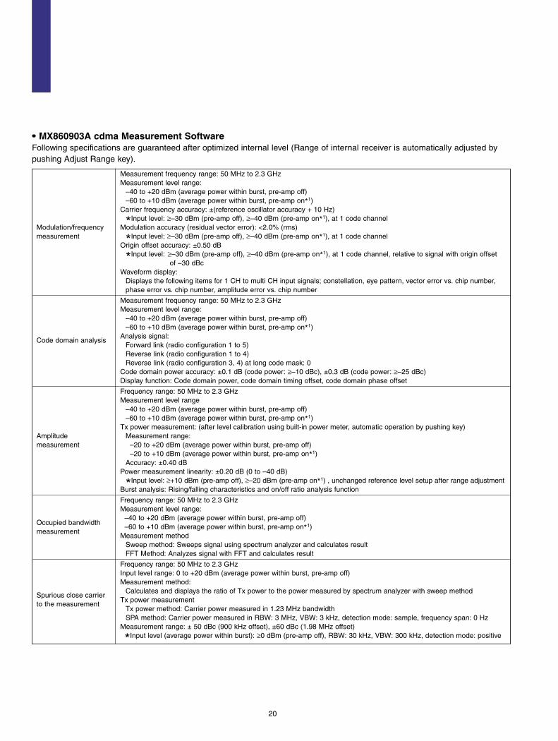
• MX860903A cdma Measurement SoftwareFollowing specifications are guaranteed after optimized internal level (Range of internal receiver is automatically adjusted bypushing Adjust Range key).
Measurement frequency range: 50 MHz to 2.3 GHzMeasurement level range:
–40 to +20 dBm (average power within burst, pre-amp off)–60 to +10 dBm (average power within burst, pre-amp on*1)
Carrier frequency accuracy: ±(reference oscillator accuracy + 10 Hz)
*Input level: ≥–30 dBm (pre-amp off), ≥–40 dBm (pre-amp on*1), at 1 code channelModulation/frequency Modulation accuracy (residual vector error): <2.0% (rms)measurement *Input level: ≥–30 dBm (pre-amp off), ≥–40 dBm (pre-amp on*1), at 1 code channel
Origin offset accuracy: ±0.50 dB
*Input level: ≥–30 dBm (pre-amp off), ≥–40 dBm (pre-amp on*1), at 1 code channel, relative to signal with origin offset of –30 dBc
Waveform display:Displays the following items for 1 CH to multi CH input signals; constellation, eye pattern, vector error vs. chip number, phase error vs. chip number, amplitude error vs. chip number
Measurement frequency range: 50 MHz to 2.3 GHzMeasurement level range:
–40 to +20 dBm (average power within burst, pre-amp off)–60 to +10 dBm (average power within burst, pre-amp on*1)
Analysis signal:Code domain analysis
Forward link (radio configuration 1 to 5)Reverse link (radio configuration 1 to 4)Reverse link (radio configuration 3, 4) at long code mask: 0
Code domain power accuracy: ±0.1 dB (code power: ≥–10 dBc), ±0.3 dB (code power: ≥–25 dBc)Display function: Code domain power, code domain timing offset, code domain phase offset
Frequency range: 50 MHz to 2.3 GHzMeasurement level range
–40 to +20 dBm (average power within burst, pre-amp off)–60 to +10 dBm (average power within burst, pre-amp on*1)
Tx power measurement: (after level calibration using built-in power meter, automatic operation by pushing key)Amplitude Measurement range:measurement –20 to +20 dBm (average power within burst, pre-amp off)
–20 to +10 dBm (average power within burst, pre-amp on*1)Accuracy: ±0.40 dB
Power measurement linearity: ±0.20 dB (0 to –40 dB)
*Input level: ≥+10 dBm (pre-amp off), ≥–20 dBm (pre-amp on*1) , unchanged reference level setup after range adjustmentBurst analysis: Rising/falling characteristics and on/off ratio analysis function
Frequency range: 50 MHz to 2.3 GHzMeasurement level range:
Occupied bandwidth–40 to +20 dBm (average power within burst, pre-amp off)
measurement–60 to +10 dBm (average power within burst, pre-amp on*1)
Measurement methodSweep method: Sweeps signal using spectrum analyzer and calculates resultFFT Method: Analyzes signal with FFT and calculates result
Frequency range: 50 MHz to 2.3 GHzInput level range: 0 to +20 dBm (average power within burst, pre-amp off)Measurement method:
Calculates and displays the ratio of Tx power to the power measured by spectrum analyzer with sweep methodSpurious close carrier
Tx power measurementto the measurement
Tx power method: Carrier power measured in 1.23 MHz bandwidthSPA method: Carrier power measured in RBW: 3 MHz, VBW: 3 kHz, detection mode: sample, frequency span: 0 Hz
Measurement range: ± 50 dBc (900 kHz offset), ±60 dBc (1.98 MHz offset)
*Input level (average power within burst): ≥0 dBm (pre-amp off), RBW: 30 kHz, VBW: 300 kHz, detection mode: positive

21
Measurement frequency range:10 MHz to 12.75 GHz (except within ±50 MHz of carrier frequency)
Input level range (Tx power): +20 to +40 dBm (average power within burst)Measurement method
Sweep method:Sweeps specified frequency range using spectrum analyzer and calculates ratio of carrier power and peak value detected during the sweep. Detection mode is average.
Spot method:Measures average power of specified frequencies in time domain using spectrumAnalyzer and calculates ratio of carrier power and measured power of the frequencies.Detection mode is average.
Search method:
Spurious measurementSweeps specified frequency range using spectrum analyzer and detects frequency of peak spurious.Measures average power of the detected frequencies in time domain using spectrum analyzer and calculates ratio of carrier power and the measured power for the frequencies.Detection mode is Average.
Tx power measurementTx power method: Carrier power measured in 1.23 bandwidthSPA method: Carrier power measured in RBW: 3 MHz, VBW: 3 kHz, detection mode: sample, frequency span: 0 Hz
Measurement range (typical)79 dB (RBW: 10 kHz, 10 to 30 MHz, Band 0)79 dB (RBW: 100 kHz, 30 to 1000 MHz, Band 0)
*Carrier frequency: 800 to 1000 MHz/1.8 to 2.2 GHz, referential value of power ratio in Tx power*2
Normal mode:76 – f [GHz] dB (RBW: 1 MHz, 1 to 3.15 GHz, Band 0)76 dB (RBW: 1 MHz, 3.15 to 7.8 GHz, Band 1)
Input impedance: 1 MΩ (parallel capacitance: <100 pF), 50 ΩBalance input
Differential voltage: 0.1 to 1 Vp-p, In-phase voltage: ±2.5 VUnbalance Input: 0.1 to 1 Vp-pDC/AC coupling: Changeable
Electric performanceMeasurement items:
(I/Q input)Modulation accuracy, code domain power, amplitude, occupied bandwidth (FFT method), I/Q level
Modulation accuracy measurement (residual vector error): <2% (rms)
*DC coupling, input level: ≥0.1 V (rms)I/Q level measurement: Measures input level of I and Q (rms, p-p)I/Q phase difference measurement:
When the CW signal is inputted to I and Q input terminals, measures and displays the phase difference between I- and Q-phase signals.
*1: Can be set when MS8609A-08 option is installed in the main frame.
*2: When carrier frequency is in a 2030.354 to 2200 MHz range, spurious will be generated at the frequency below.f (spurious) = f (input) – 2030.345 MHz

22
• MX860905A π/4DQPSK Measurement SoftwareFollowing specifications are guaranteed after optimized internal level (Range of internal receiver is automatically adjusted bypushing Adjust Range key).
Measured frequency range: 50 MHz to 2.1 GHzMeasured level ranges:
–40 to +20 dBm (average power within burst, pre-amp off*1)–60 to +10 dBm (average power within burst, pre-amp on*1)
Carrier frequency accuracy: ± (reference oscillator accuracy + 10 Hz)
*Input level (average power within burst): ≥–30 dBm (pre-amp off*1), ≥–40 dBm (pre-amp on*1)Modulation accuracy (residual vector error)
PDC/NADC: <0.5% (rms), PHS: <0.7% (rms)
Modulation/frequency *Input level: ≥–30 dBm (pre-amp off*1), ≥–40 dBm (pre-amp on*1), averaging: 10 times
measurementOrigin offset accuracy: ±0.50 dB
*Input level (average power within burst): ≥–30 dBm (pre-amp off*1), ≥–40 dBm (pre-amp on*1), relative to signal with origin offset of –30 dBc
Transmission rate accuracy: ±1 ppm
*Input level (average power within burst): ≥–30 dBm (pre-amp off*1), ≥–40 dBm (pre-amp on*1)Symbol rate: 2 to 300 k symbol/sRoll off ratio: 0.2 to 1.0Analysis symbol: 48 to 1000 symbolWaveform displays:
Constellation, eye diagram, EVM vs. symbol No., phase error vs. symbol No., amplitude error vs. symbol No.
Frequency range: 50 MHz to 2.1 GHzMeasurement level ranges:
–40 to +20 dBm (average power within burst, pre-amp off*1)–60 to +10 dBm (average power within burst, pre-amp on*1)
Transmitter power measurement*1
Measurement ranges:–10 to +20 dBm (average power within burst, pre-amp off*1)–10 to +10 dBm (average power within burst, pre-amp on*1)Accuracy: ±0.40 dB
Power measurement linearity: ±0.20 dB (0 to –30 dB)Amplitude *Input level (average power within burst): ≥–10 dBm (pre-amp off*1), ≥–20 dBm (pre-amp on*1), without changing the measurement reference level setting after range optimization
Carrier-off power measurement*3
Normal mode measurement rangePDC/NADC: ≥65 dB, PHS: ≥60 dB *Relative to average power within burst
Wide dynamic range mode measurement rangePDC/PHS: ≥90 dB (measurement limits of average noise level: ≤–80 dBm, 50 Hz to 2.1 GHz)PHS: ≥80 dB (measurement limits of average noise level: ≤–70 dBm, 50 Hz to 2.1 GHz)
*Average power within burst: 10 mWRise/fall characteristics:
Display rising/falling edges while synchronizing to modulation data of signal data to be measured.Standard line display, NO/GO judgement function
Measured frequency range: 50 MHz to 2.1 GHzMeasured level ranges:
Occupied bandwidth–40 to +20 dBm (average power within burst, pre-amp off*1)
measurement–60 to +10 dBm (average power within burst, pre-amp on*1)
Measurement methodsSweep method: Calculates and displays result after signal measured with sweep spectrum analyzerFFT method: Calculates and displays result after FFT
23
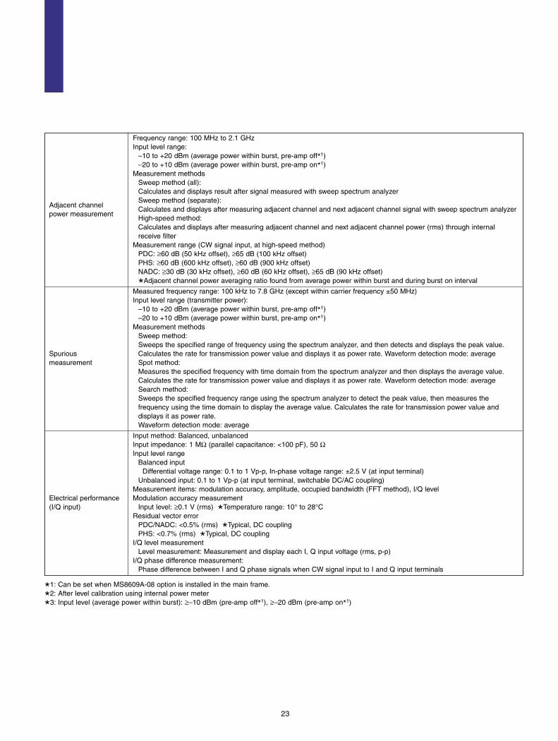
Frequency range: 100 MHz to 2.1 GHzInput level range:
–10 to +20 dBm (average power within burst, pre-amp off*1)–20 to +10 dBm (average power within burst, pre-amp on*1)
Measurement methodsSweep method (all):Calculates and displays result after signal measured with sweep spectrum analyzer
Adjacent channelSweep method (separate):
power measurementCalculates and displays after measuring adjacent channel and next adjacent channel signal with sweep spectrum analyzerHigh-speed method:Calculates and displays after measuring adjacent channel and next adjacent channel power (rms) through internal receive filter
Measurement range (CW signal input, at high-speed method)PDC: ≥60 dB (50 kHz offset), ≥65 dB (100 kHz offset)PHS: ≥60 dB (600 kHz offset), ≥60 dB (900 kHz offset)NADC: ≥30 dB (30 kHz offset), ≥60 dB (60 kHz offset), ≥65 dB (90 kHz offset)
*Adjacent channel power averaging ratio found from average power within burst and during burst on interval
Measured frequency range: 100 kHz to 7.8 GHz (except within carrier frequency ±50 MHz)Input level range (transmitter power):
–10 to +20 dBm (average power within burst, pre-amp off*1)–20 to +10 dBm (average power within burst, pre-amp on*1)
Measurement methodsSweep method:Sweeps the specified range of frequency using the spectrum analyzer, and then detects and displays the peak value.
Spurious Calculates the rate for transmission power value and displays it as power rate. Waveform detection mode: averagemeasurement Spot method:
Measures the specified frequency with time domain from the spectrum analyzer and then displays the average value. Calculates the rate for transmission power value and displays it as power rate. Waveform detection mode: averageSearch method:Sweeps the specified frequency range using the spectrum analyzer to detect the peak value, then measures the frequency using the time domain to display the average value. Calculates the rate for transmission power value and displays it as power rate.Waveform detection mode: average
Input method: Balanced, unbalancedInput impedance: 1 MΩ (parallel capacitance: <100 pF), 50 ΩInput level range
Balanced inputDifferential voltage range: 0.1 to 1 Vp-p, In-phase voltage range: ±2.5 V (at input terminal)
Unbalanced input: 0.1 to 1 Vp-p (at input terminal, switchable DC/AC coupling)Measurement items: modulation accuracy, amplitude, occupied bandwidth (FFT method), I/Q level
Electrical performance Modulation accuracy measurement(I/Q input) Input level: ≥0.1 V (rms) *Temperature range: 10° to 28°C
Residual vector errorPDC/NADC: <0.5% (rms) *Typical, DC couplingPHS: <0.7% (rms) *Typical, DC coupling
I/Q level measurementLevel measurement: Measurement and display each I, Q input voltage (rms, p-p)
I/Q phase difference measurement:Phase difference between I and Q phase signals when CW signal input to I and Q input terminals
*1: Can be set when MS8609A-08 option is installed in the main frame.
*2: After level calibration using internal power meter
*3: Input level (average power within burst): ≥–10 dBm (pre-amp off*1), ≥–20 dBm (pre-amp on*1)

Options
24
• Option 01: Precision frequency reference
Frequency 10 MHz
Start-up characteristics ≤5 x 10⁻⁸/7 min. (with the frequency at 24 hours after the power is turned on referenced)
Aging rate ≤±5 x 10⁻¹⁰/day (with the frequency at 24 hours after the power is turned on referenced)
Temperaturecharacteristics
≤±5 x 10⁻¹⁰ (with the frequency at 0 to 50˚C and 25˚C referenced)
• Option 02: Narrow resolution bandwidths (FFT)
Setting range: 1 Hz to 1 kHz (1, 3 sequence)
Resolution bandwidthBandwidth accuracy: ±10% (RBW = 30, 300 Hz), ±10% Typical (RBW = 1, 3, 10, 100, 1 kHz)RBW selectivity (60 dB: 3 dB): ≤5:1RBW switching uncertainty: ±0.5 dB
Span setting Minimum setting span: 100 Hz
When RBW is 1 Hz, RF ATT is 0 dB, sample detection mode≤–146.5 dBm + 1.5 x f [GHz] dB Typical (1 MHz to 2.5 GHz, band 0)
Average noise level≤–142.5 dBm + 1.5 x f [GHz] dB Typical (2.5 to 3.2 GHz, band 0)
display≤–138.5 dBm Typical (3.15 to 7.8 GHz, band 1)≤–129.5 dBm Typical (7.7 to 13.2 GHz, band 2)
• Option 04: Digital resolution bandwidth
Setting range: 10 Hz to 1 MHz (1, 3 sequence)Bandwidth accuracy: ±10% (RBW ≥100 Hz), ±10% Typical (RBW ≤30 Hz)
Resolution bandwidthBandwidth selectivity (60 dB: 3 dB): ≤5:1 (RBW ≥100 Hz), ≤5:1 Typical (RBW ≤30 Hz)RBW switching uncertainty: ±0.5 dB
Detection modeNORMAL, POSITIVE PEAK, NEGATIVE PEAK, SAMPLE, RMSRMS: displays root-mean-square value of average power between sample points
Without Option 08, when RBW is 10 Hz, RF ATT is 0 dB, sample detection mode≤–136.5 dBm + f [GHz] dB Typical (1 MHz to 2.5 GHz, band 0)≤–132.5 dBm + f [GHz] dB Typical (2.5 to 3.2 GHz, band 0)≤–128.5 dBm Typical (3.15 to 7.8 GHz, band 1)
Average noise level ≤–119.5 dBm Typical (7.7 to 13.2 GHz, band 2)display With Option 08, when RBW is 10 Hz, RF ATT is 0 dB, sample detection mode
≤–134.5 dBm + 1.8 x f [GHz] dB Typical (1 MHz to 2.5 GHz, band 0)≤–132.5 dBm + 1.8 x f [GHz] dB Typical (2.5 to 3.2 GHz, band 0)≤–128.5 dBm Typical (3.15 to 7.8 GHz, band 1)≤–119.5 dBm Typical (7.7 to 13.2 GHz, band 2)
• Option 05: Rubidium reference oscillator
Frequency 10 MHz
Start-up characteristics ±1 x 10⁻⁹/7 min. (with frequency one hour after the power is turned on referenced)
Aging rate ±1 x 10⁻¹⁰/month (with frequency one hour after the power is turned on referenced)
Temperaturecharacteristics
±1 x 10⁻⁹ (with frequency at 0 to 45˚C and 25˚C referenced)
Accessories J1066 coaxial code 0.15 m (BNC211-LP4)

*1: Pre-amplifier input level is shown by the following equation: Pre-amplifier input level = RF input level – RF ATT setting level
• Option 08: Pre-amplifier
Gain 20 dB typical
Noise figure 6.5 dB typical (input frequency: ≤2 GHz) ,12 dB (input frequency: >2 GHz)
Frequency range: 100 kHz to 3 GHz
FrequencyBand
0: 100 kHz to 3.0 GHz, 1–: 3.15 to 6.3 GHz, 1+: 6.2 to 7.8 GHz, 2+: 7.7 kHz to 13.2 GHz
*The band, which can use with a pre-amplifier, is only band 0.
Level measurement: Average noise level to +10 dBmMax. input level: +10 dBmAverage noise level: –137 dBm + 2.0 x f [GHz] dB (1 MHz to 2.5 GHz, band 0)
*At RBW 300 Hz, VBW 1 Hz, RF ATT 0 dB, and detection mode of SAMPLEReference level
Setting rangeLog scale: –120 to +10 dBm, or equivalent levelLinear scale: 2.24 µV to 707 mV
Reference level accuracy: ±0.90 dB (–69.9 to +10 dBm), ±1.50 dB (–90 to –70 dBm)
*After calibration, with 50 MHz referenced, 1 MHz span (RF ATT, RBW, VBW, and sweep time are set to AUTO)RBW switching uncertainty: ±0.5 dB (300 Hz to 5 MHz), ±0.75 dB (10 MHz, 20 MHz)
Amplitude *After calibration, with RBW 3 kHz referencedRF ATT switching uncertainty: ±0.5 dB (10 to 50 dB), ±1.0 dB (52 to 62 dB)Frequency response: ±2.0 dB (100 kHz to 3 GHz)
*With 100 MHz referenced, when RF ATT is 10 to 50 dB, and temperature is 18 to 28˚CLinearity of waveform display
Log scale (after calibration): ±0.5 dB (0 to –20 dB, RBW ≤1 kHz), ±1.0 dB (0 to –60 dB, RBW ≤1 kHz), ±1.5 dB (0 to –75 dB, RBW ≤1 kHz)
Linear scale (after calibration): ±5% (relative to reference level)Spurious response: Two-tone 3rd order distortion: ≤–70 dBc (10 MHz to 3 GHz)
*Frequency difference of two signals ≥50 kHz, at pre-amplifier input level*1 of –55 dBm 1 dB gain compression: ≥–35 dBm (input frequency ≥100 MHz) *At pre-amplifier input level*1
Input impedance: VSWR ≤2.5 typical
• Option 30: LPF for 2 GHz band carrier cut
This is for suppression the distortion inside spectrum analyzer by the carrier wave (1.8 to 2 GHz) in W-CDMA low frequency Function band spurious measurement.
*Option 08 cannot be installed simultaneously.
Frequency range 9 kHz to 3.2 GHz (LPF: OFF), 9 kHz to 1.0 GHz (LPF: ON)
LPF attenuationcharacteristics
≤–20 dB, –30 dB typical, at 1.8 to 2.2 GHz
[LPF: ON]Average noise level
≤–122 dBm + 2.0 x f [GHz] dB (1 MHz to 1.0 GHz, band 0)display
*RBW: 300 Hz, VBW: 1 Hz, RF ATT: 0 dB
[LPF: ON]Frequency response ±1.0 dB (9 kHz to 1.0 GHz, band 0 )
*With 50 MHz referenced, when RF ATT is 10 dB, and temperature is 18 to 28˚C
25
• Option 09: Ethernet interface
Function Control with external controller (except for power switch)
Connector 10BASE-T

26
• Option 32: Maximum Input Level Extension
Function The measurement level range is extended changed to +26 dBm
Max. input level +30 dBm (1 W), continuous wave average power
Power meter function Level range: –14 to +26 dBm
Setting rangeLog scale: –100 to +40 dBm or Equivalent level
Spectrum analyzerLinear scale: 22.4 µV to 22.4 V
amplitudeReference level accuracy:
±0.75 dB (+0.1 to +30 dBm), ±0.5 dB (–49.9 to 0 dBm), ±0.75 dB (–69.9 to –50 dBm), ±1.5 dB (–80 to –70 dBm)
*After calibration, with frequency 50 MHz when span 1 MHz (RF ATT, RBW, VBW, and sweep time set to AUTO)
• Option 33: High accuracy power measurement
FunctionPower measurement accuracy is improved without using the internal power meter when MX860901A W-CDMA measurement software is used.
Frequency range 1848 to 2171 MHz (Except 1995 to 2105 MHz)
Transmission power measurement range
–50 dBm to +20 dBm (average power)
Reference level –10 dBm to +20 dBm
Transmission ±0.4 dBpower accuracy *At reference input level, 25˚ ±3˚C, input ATT: AUTO, after calibration and except mismatch error
Power measurement ±0.2 dB (0 to –40 dB)linearity *Input level: ≥–10 dBm, at range optimization and no change of reference level setting.
Temperature coefficient 0.015 dB/˚C
Accessories ATA flash memory card
Calibration interval Six months
• Option 46: Auto power recovery
Disables the power switch on the front panel and automatically restores power after power failure.
FunctionON/OFF operation can be performed using the standby switch on the rear panel.
*Power switch on the front panel of this unit does not have a latching function. Therefore, if power is interrupted in the ON status, the standby status is kept even after power is restored.
• Option 47: Rack mount (IEC)
Function Mounts the rack mount for IEC standard-compatible rack. When mounted, the tilt handle (standard) is eliminated.
• Option 48: Rack mount (JIS)
Function Mounts the rack mount for JIS standard-compatible rack. When mounted, the tilt handle (standard) is eliminated.
• Option 31: Low noise floor
Function This is used to decrease the floor noise in frequency band 2+.
Average noise leveldisplay
≤–112 dBm (7.7 to 13.2 GHz, band 2) *RBW: 300 Hz, VBW: 1 Hz, RF ATT: 0 dB

27
Ordering Information
Please specify the model/number, name, and quantity when ordering.
Model/Order No. Name
MS8609A Digital Mobile Radio Transmitter Tester
Power cord, 2.6 m: 1 pcJ0996 RS-232C cable: 1 pcJT32MA3-NT1 PC-ATA card (32 MB): 1 pcF0014 Fuse, 6.3 A: 1 pcJ0576B Coaxial cord (N-P • 5D-2W • N-P), 1 m: 1 pcMX268001A File Transfer Utility: 1 pcW1709AE MS8608A/MS8609A operation manual (Vol. 1): 1 copyW1744AE MS8608A/MS8609A operation manual (Vol. 2): 1 copyW1745AE MS8608A/MS8609A operation manual (Vol. 3): 1 copy
MS8609A-01 Precision frequency reference (aging rate: 5 x 10⁻¹⁰/day)MS8609A-02 Narrow resolution bandwidth (FFT)MS8609A-04 Digital resolution bandwidthMS8609A-05 Rubidium reference oscillatorMS8609A-08 Pre-amplifierMS8609A-09 Ethernet interface MS8609A-30 LPF for 2 GHz band carrier cutMS8609A-31 Low noise floorMS8609A-32 Maximum input level extensionMS8609A-33 High accuracy power measurementMS8609A-46 Auto-power recoveryMS8609A-47 Rack mount without handle (JIS)MS8609A-48 Rack mount without handle (IEC)
Options
Standard accessories
Main frame
Model/Order No. Name
MX860901B W-CDMA Measurement SoftwareMX860902A GSM Measurement Software MX860903A cdma Measurement SoftwareMX860905A π/4DQPSK Measurement SoftwareW1746AE MX860801A/B, MX860901A/B operation manualW1795AE MX860802A/MX860902A operation manual W1865AE MX860803A/MX860903A operation manualW1866AE MX860805A/MX860905A operation manual
J0576D Coaxial cord (N-P • 5D-2W • N-P), 2 mJ0127C Coaxial cord (BNC-P • RG-58A/U • BNC-P), 0.5 m J0127A Coaxial cord (BNC-P • RG-58A/U • BNC-P), 1 m J0007 GPIB cable, 1 m J0008 GPIB cable, 2 mMA1612A Four-Point Junction Pad (5 to 3000 MHz)J0395 High-power fixed attenuator (30 dB, 30 W, DC to 8 GHz)B0472 High-power fixed attenuator (30 dB, 100 W, DC to 18 GHz)B0452A Hard carrying case (with casters)B0452B Hard carrying case (without casters)B0329G Front cover (3/4 MW4U)B0488 Rear panel protective padB0480 Tilt handle soft type
MS8609A-90 Extended three year warranty serviceMS8609A-91 Extended five year warranty service
Maintenance service
Optional accessories
Measurement software

ANRITSU CORPORATIONMEASUREMENT SOLUTIONS5-10-27, Minamiazabu, Minato-ku, Tokyo 106-8570, JapanPhone: +81-3-3446-1111Telex: J34372Fax: +81-3-3442-0235
• U.S.A.ANRITSU COMPANYNorth American Region Headquarters1155 East Collins Blvd., Richardson, Tx 75081, U.S.A.Toll Free: 1-800-ANRITSU (267-4878)Phone: +1-972-644-1777Fax: +1-972-671-1877
• CanadaANRITSU ELECTRONICS LTD.Unit 102, 215 Stafford Road West Nepean, Ontario K2H 9C1, Canada Phone: +1-613-828-4090 Fax: +1-613-828-5400
• Brasil ANRITSU ELETRÔNICA LTDA.Praia de Botafogo 440, Sala 2401 CEP 22250-040, Rio de Janeiro, RJ, Brasil Phone: +55-21-5276922 Fax: +55-21-537-1456
• U.K.ANRITSU LTD.200 Capability Green, Luton, Bedfordshire LU1 3LU, U.K.Phone: +44-1582-433200 Fax: +44-1582-731303
• GermanyANRITSU GmbHGrafenberger Allee 54-56, 40237 Düsseldorf, Germany Phone: +49-211-96855-0 Fax: +49-211-96855-55
• FranceANRITSU S.A.9, Avenue du Québec Z.A. de Courtabœuf 91951 LesUlis Cedex, France Phone: +33-1-60-92-15-50Fax: +33-1-64-46-10-65
• ItalyANRITSU S.p.A.Via Elio Vittorini, 129, 00144 Roma EUR, ItalyPhone: +39-06-509-9711 Fax: +39-06-502-24-25
• SwedenANRITSU ABBotvid Center, Fittja Backe 1-3 145 84 Stockholm,SwedenPhone: +46-853470700 Fax: +46-853470730
• SpainANRITSU ELECTRÓNICA, S.A.Europa Empresarial Edificio Londres, Planta 1, Oficina6 C/ Playa de Liencres, 2 28230 Las Rozas. Madrid,SpainPhone: +34-91-6404460Fax: +34-91-6404461
• SingaporeANRITSU PTE LTD.10, Hoe Chiang Road #07-01/02, Keppel Towers,Singapore 089315 Phone: +65-6282-2400 Fax: +65-6282-2533
• Hong Kong ANRITSU COMPANY LTD.Suite 719, 7/F., Chinachem Golden Plaza, 77 ModyRoad, Tsimshatsui East, Kowloon, Hong Kong, ChinaPhone: +852-2301-4980Fax: +852-2301-3545
• KoreaANRITSU CORPORATION14F Hyun Juk Bldg. 832-41, Yeoksam-dong, Kangnam-ku, Seoul, KoreaPhone: +82-2-553-6603Fax: +82-2-553-6604˜ 5
• AustraliaANRITSU PTY LTD.Unit 3/170 Forster Road Mt. Waverley, Victoria, 3149,AustraliaPhone: +61-3-9558-8177Fax: +61-3-9558-8255
• TaiwanANRITSU COMPANY INC.6F, 96, Sec. 3, Chien Kou North Rd. Taipei, TaiwanPhone: +886-2-2515-6050Fax: +886-2-2509-5519
Specifications are subject to change without notice.
Catalog No. MS8609A-E-A-1-(3.00) Printed in Japan 2002-4 30KL/M