msig volume iii - sewer networks and pump stations
DESCRIPTION
Sewerage DesignTRANSCRIPT


Malaysian SewerageIndustry Guidelines
Volume IIISEWER NETWORKS AND
PUMP STATIONS
Third EditionNational Water Services Commission (SPAN)
© Copyright National Water Services Commission
All rights reserved.
This publication is protected by copyright.
No part of this publication may be reproduced, distributed, transmitted, stored in a retrieval system, or reduced to any electronic medium without the written authority of the Commissioner, National Water Services Commission.
National Water Services Commission and Registered Certifying Agencies employees are permitted to copy and use the information in this publication, for internal purposes only.
Changes may be made periodically to the information herein.
ISBN 978-983-44456-0-7
Third Edition
January 2009
Published bySuruhanjaya Perkhidmatan Air Negara (SPAN)(National Water Services Commission)Prima Avenue 7, Block 3510Jalan Teknokrat 663000 Cyberjaya SelangorMalaysia

FOREWORD BY THE CEO OF SPAN
Since independent, the wastewater treatment technology in Malaysia have evolved through the introduction of new systems in the industry. Since then basic sanitation
facilities as overhang latrines, pit and bucket systems and pour flush systems were slowly replaced by more modern systems like aerated lagoons, activated sludge system, package systems and variety of mechanical plant. However, sewage still remains as one of the major pollutants of our inland waterways. In the 1900s, the emergent of new treatment technologies were mainly driven by the basic need to treat the sewage so as to control waterborne diseases. Today, the environmental regulations including effluent discharge standards are becoming more stringent with increasing awareness toward sustainable environmental management. Public are also more educated and more alert on the need to preserve the water source and the environment. Hence the introduction of more innovative design in municipal wastewater treatment technologies is needed in order to meet the stricter regulatory requirements.
Faster approvals of sewerage system provide better development potential within an area while standardization of system and equipment will lead to better operational efficiencies. Thus the first edition of the guidelines for sewerage industry entitled “Design and Installation of Sewerage Systems” was introduced in 1995. The main purpose of these guidelines is to assist the developer and professionals to plan and design sewerage systems that comply with the regulatory requirements. Certainly those guidelines have successfully paved the road towards nurturing a more structured sewerage industry development.
The National Water Services Commission (SPAN) has completed the exercise initiated by the Sewerage Services Department to review and improve those guidelines. The new revised documents were renamed as the “Malaysian Sewerage Industry Guidelines” which comprise of five (5) volumes.
These new revisions incorporated invaluable knowledge gained by various stakeholders in the sewerage sector over the past decade. SPAN would like to thank all parties involved in the revision exercise. It is hoped that the publication of the third edition of this volume will further improve the sewage system development in this country.
Chief Executive OfficerNational Water Services Commission (SPAN)


i
Table of ConTenTs Page
Section 1 Introduction 1.1 Purpose of This Volume 3
1.2 Who Should Use This Volume 3
1.3 Related Reference Material 3
Section 2 Planning, Material and Design 2.1 Sewers 13 2.1.1 Pipe Material Selection Factors 13
2.1.2 Pipe Materials and Fittings 14
2.1.3 Pipe Selections 15
2.1.4 Requirements and Limitations for Use of Certain 16 Pipe Material
2.1.5 VitrifiedClayPipe 17
2.1.6 Reinforced Concrete Pipe 18
2.1.7 DuctileIronPipe 19
2.1.8 Steel Pipe 20
2.1.9 SolidWallPEPipe 21
2.1.10 ProfiledWallPEPipe 21
2.1.11 Glass Reinforced Plastic Pipe 22
2.1.12 AcrylonitrileButadieneStyrenePipe 23
2.1.13 SewerDesign-GeneralRequirements 24
2.1.14 FlowRateEstimations 24
2.1.15 Sewer Cleansing Velocities 25
2.1.16 Pipe Roughness 26
2.1.17 DesignofGravitySewer 27
2.1.18 DesignofForceMains 29
2.1.19 VacuumSewerageSystem 31
2.1.20 ComputerisedSewerDesigns 45
2.1.21 DesignofInvertedSiphon 45
2.1.22 StructuralDesignofSewers 46
ii
2.2 Manhole 50 2.2.1 General 50 2.2.2 Manhole Location 52 2.2.3 Pipe Lengths from Manhole 53 2.2.4 StructuralDesignConsiderationsforManhole 53 2.3 ManholeCoversandFrames 55 2.3.1 General 55 2.3.2 Load Class 55 2.3.3 Material 55 2.3.4 Dimensions,MarkingandSurfaceFinish 55 2.3.5 Seating 55 2.3.6 Casting 56 2.3.7 ProtectiveCoating 56 2.3.8 Water-tightness 56 2.3.9 SafetyFeatures 56 2.3.10 ProductCertification 57 2.4 DesignofNetworkPumpStations 57 2.4.1 SpecifyingofNetworkPumpStations 57 2.4.2 General Requirements 58 2.4.3 BufferRequirements 58 2.4.4 PipeworkRequirements 58 2.4.5 Wet-wellRequirements 59 2.4.6 Dry-wellRequirements 60 2.4.7 StructuralRequirements 60 2.4.8 Ventilation Requirements 61 2.4.9 OdourControl 61 2.4.10RequirementsforLightingandElectricalFittings 62 2.4.11AcceptablePumpSystem(FixedSpeedPumps 62 Only) 2.4.12 ValveRequirements 63 2.4.13RequirementsforLevelControls 64 2.4.14 Requirements for Alarms 64 2.4.15 RequirementsofHydraulicDesignandPerformance 64 2.4.16 Maintenance Considerations 65 2.4.17 HazardandOperability 65 2.4.18OtherRequirements 65

iii
2.5 Interceptors 68 2.5.1 OilInterceptors 68 2.5.2 Grease Traps 68 2.6 ConcreteandReinforcementRequirements 69 2.6.1 Concrete 69 2.6.2 Cement 69 2.6.3 SteelReinforcementandFalsework 70
Section 3 Construction and Installation 3.1 Introduction 73 3.2 PipesandFittingsDeliveryandHandling 73 3.2.1 PipesandFittingsDelivery 73 3.2.2 PipeHandlingatSite 74 3.2.3 PipeStorage 75 3.2.4 PipeDamage 76 3.3 TrenchExcavation 77 3.3.1 ProtectionofAffectedServices,Structures, 77 PavementsandVegetation 3.3.2 ExcavationRequirements 78 3.3.3 BoredExcavation 80 3.4 PipeLaying 80 3.4.1 PipeBedding 80 3.4.2 Pipe and Fittings Placement 81 3.4.3 PipeJacking 82 3.4.4 Concrete Pipe Support 83 3.4.5 Pipe Cutting 83 3.4.6 BackfillofTrench 84 3.4.7 OtherGeneralRequirements 84 3.5 Pipe Jointing 85 3.5.1 FlexibleJoints 85 3.5.2 SolventWeldJoints 86 3.5.3 FlangedJoints 87 3.5.4 SteelPipeWeldedJoints(FieldWelding) 87 3.5.5 PolyethyleneButtWeldedJoints 88
iv
3.6 Special Requirements For Sewer 88 3.6.1 ThrustBlocksforPressurePipelines 88 3.6.2 PipeRestraintsandBulkheadsonSteepSlopes 89 3.6.3 PipeEmbedmentandOverlay 89 3.6.4 SleevingofDuctileIronPipe 90 3.6.5 ‘Rocker’PipeConnectionstoManholes 90 3.7 Reinstatement 90 3.8 ConnectionstoPublicSewers 91 3.8.1 General 91 3.8.2 JunctionConnections 92 3.8.3 SaddleConnections 92 3.8.4 ManholeConnections 93
Section 4 Sewer Testing 4.1 General 97 4.2 TestingofGravitySewers 98 4.3 TestingofForceMains 99 4.4 Testing of Manhole and other ancillaries 100 4.5 Low Pressure Air Test 100 4.5.1 General 100 4.5.2 Procedure for Testing 101 4.5.3 Procedures for Handling Air Test Failure 102 4.6 Low Pressure Water Test 102 4.6.1 General 102 4.6.2 Procedure 103 4.6.3 Handling Water Test Failures 104 4.7 HighPressureWaterTest 104 4.7.1 General 104 4.7.2 Procedure 104 4.8 HighPressureLeakageTest 106 4.8.1 General 106 4.8.2 Procedure 106 4.9 TestforStraightness,ObstructionandGradient 106 4.10 CCTVInspection 107 4.10.1 ObjectivesofCCTVInspection 107
v
4.10.2 TechnicalRequirementsandReferences 107 4.10.3 EquipmentSpecificationsandTestDevices 108 4.10.4 CCTVInspectionRequirements 108 4.10.5 CCTVInspectionImplementationProcedurefor 110 NewSewerNetwork 4.10.6 InterpretationOfResultsFromCCTVInspection 111 4.10.7 Follow-UpActiontoBeTaken 112 4.11 InfiltrationTest 114 4.11.1 General 114 4.11.2 Procedure 114 4.11.3 Handling Test Failures 114 4.12 Water-tightnessTest 114 4.12.1 General 114 4.12.2 Procedures 115

vi
lisT of Tables
Table2.1a NormalPipeRoughnessforGravitySewer 27Table2.1b NormalPipeRoughnessforForceMainsforAllPipe 27 Materials Table2.2 TypicalRoughnessCoefficient,ks 28Table2.3 TypicalManningCoefficient,n 28Table2.4 TypicalHazen-WilliamsCoefficient,C 29Table 2.5 Condition/alarm of the station equipment 45Table2.6 MinimumManholeDiameters 51Table2.7 Finalinspectionandtesting 57Table2.8 RecommendedDesignParametersforPumpStations 66Table4.1 TestDuration 101Table4.2 DefectGradesDescriptions 113
Appendix A Typical Drawings/Diagrams
FigureA1 StandardManholeCover 119FigureA2 PlanViewofTypicalManhole 120FigureA3 TypicalShallowPrecastConcreteManhole 121 (GroundLeveltoInvertofPipe1.2m≤Depth<2.5mFigureA4 TypicalShallowPrecastConcreteManholewithBackdrop 122 (GroundLeveltoInvertofPipe1.2m≤Depth<2.5m)FigureA5 TypicalMediumPrecastConcreteManhole 123 (GroundLeveltoInvertofPipe2.5m≤Depth<5m)FigureA6 TypicalMediumPrecastConcreteManholewithbackdrop 124 (GroundLeveltoInvertofPipe2.5m≤Depth<5m)FigureA7 TypicalDeepPrecastConcreteManhole 125 (GroundLeveltoInvertofPipe5m≤Depth≤9m)FigureA8 TypicalDeepPrecastConcreteManholewithBackdrop 126 (GroundLeveltoInvertofPipe5m≤Depth≤9m)FigureA9 TypicalDetailsofLargeDiameterManhole(LDM)Type 127FigureA10 TypicalInductVentDetail 128FigureA11 DetailsofHouseholdConnectiontoMainSewer 129 Reticulation Pipe for V.C. Pipe FigureA12 TypicalDetailsofConcreteThrustandAnchorBlock 130FigureA13(a) TypicalDetailsofInvertedSiphonsorDepressedSewer 131
vii
FigureA13(b) TypicalDetailsofInvertedSiphonsorDepressedSewer 132FigureA14(a) TypicalDetailsforForceMain–ScourValveandReceiving 133 Manhole(Sheet1to2)FigureA14(b) TypicalDetailsofForceMain–AirValve(Sheet1to2) 134FigureA15 TypicalDetailofForceMainCrossing 135FigureA16(a) StandardPipeBeddings(Sheet1to2) 136FigureA16(b) StandardPipeBeddings(Sheet1to2) 137FigureA17 Vacuumsewagecollectionsystem 138FigureA19(a) Exampleofvacuumstationwithhousedcollectionvessel 139FigureA19(b) Exampleofvacuumstationwithhousedcollectionvessel 140FigureA20(a) Collectionchamberswithinterfacevalvesventedthrough 141 breather pipesFigureA20(b) Collectionchamberwithinterfacevalveactivatedbyfloat 141FigureA20(c) Multi-valvecollectionchamber 142FigureA21 Vacuumsewerprofiles(nottoscale) 143FigureA22 Exampleofvacuumsewerprofilesforuphillanddownhill 143 transport(nottoscale)FigureA23 Y-branchforvacuumsewer 144FigureA24 Methodofjoiningcrossoverpipesandbranchsewersto 144 vacuummainsFigureA25 Typicaldetailsofdry-wellpumpstation 145FigureA26 Typicaldetailofwet-wellpumpstation 146FigureA27 BufferZoneforPumpStationwithSuperStructure 147FigureA28 BufferZoneforPumpwithoutSuperStructure 148FigureA29 StandardSymbolsandAbbreviations 149
Appendix B Tables
TableB1 ClassesofRigidPipeRequiredforVariousDepth 153
Appendix C CCTV Format and Codes
AppendixC1 ReportformatforCCTVInspection 157AppendixC2 ReportformatforCCTVInspection 158AppendixC3 ReportformatforCCTVInspection 159AppendixC4 ReportformatforCCTVInspection 160AppendixC5 ReportformatforCCTVInspection 161AppendixC6 Modules 162


Section 1
Introduction


Introduction
Volume 3 3Sewer Networks and Pump Stations
1.1 Purpose of This Volume
This volume sets out the requirements of the National Water Services Commission (SPAN) (referred to as the Commission in this document) for the design, construction and testing of sewer networks and network pump stations.
The owner must comply with the requirements set out in this volume when submitting an application for the approval of the Commission.
This volume generally does not cover internal plumbing systems within buildings. However, some guidelines are provided on the provision of interceptors to protect public sewers from the discharge of oil and grease from garage workshops, hotels, restaurants, canteens or any premises that collect such matter.
1.2 Who Should Use This Volume
This volume is primarily intended for owners, developers, consulting engineers, sewerage contractors, manufacturers, planners, and Public Authorities who have a direct interest in the planning, design and installation of sewer networks and/or network pump stations.
1.3 Related Reference Material
This volume does not cover all aspects of design and construction of sewer networks and network pump stations. Where information is not covered in this volume, the designer shall follow the requirements given in MS 1228.
MS 1228 shall take precedence over other foreign standards in the event when there are discrepancies on the requirements.
The following documents are also referred to in this volume.
a) Malaysian Standards
i) MS 28 Specification for test for water for making concrete
ii) MS 29 Specification for aggregates from natural sources for concrete
iii) MS 144 Specification for cold reduced mild steel wire for reinforcement of concrete

Volume 3
Introduction
Malaysian SewerageIndustry Guidelines
4
iv) MS 145 Specification for steel welded fabric for the reinforcement of concrete.
v) MS 146 Specification for hot rolled steel bars for the vi) MS 522 Specification for Portland cement (ordinary
and rapid hardening)vii) MS 523 Specification for concrete including ready
mixed concreteviii) MS 628 Specification for unplasticised PVC (uPVC)
pipes for water supplyPart 1 : PipesPart 2 : Joints and fittings for use with unplasticised PVC pipes
ix) MS 672 Specification of rubber seals in water supply, drainage and sewerage pipelines
x) MS 740 Specification for hot-dip galvanized coatings on iron and steel articles
xi) MS 822 Specification for sawn timber foundation piles
xii) MS 881 Specification for pre-cast concrete pipes and fittings for drainage and seweragePart 1 : Specification for pipes and fittings with flexible joints and manholes
xiii) MS 922 Specification for concrete admixturesPart 1 : Accelerating admixtures, retarding admixtures and water-reducing admixtures
MS 923 Specification for joints and fittings for use with uPVC pressure pipes [delete]Part 3 : Mechanical joints and fittings, principally of uPVC [delete]
xiv) MS 979 Specification for unplasticizes sewerage pipes and fittingsPart 1 : Pipes of diameter 100mm and 155mmPart 2 : Pipes of diameter 200mm and above
xv) MS 980 Specification for safety signs and colours : Colorimetric and photometric properties of materials
xvi) MS 981 Specification for safety signs and colours : Colour and design
Introduction
Volume 3 5Sewer Networks and Pump Stations
xvii) MS 982 Specification for fire safety signs, notices and graphic symbols.
xviii) MS 1037 Specification for sulphate-resisting Portland cement
xix) MS 1058 MS 1058 Specification for polyethylene (PE) piping systems for water supplyPart 1 : GeneralPart 2 : Pipes
xx) MS 1061 Vitrified clay pipes and fittings and pipe joints for drains and sewers
xxi) MS 1195 Code of practice for structural use of concrete
xxii) MS 1227 Specification for Portland pulverised fuel ash cement
xxiii) MS 1228 Code of Practice for Design and Installation of Sewerage Systems
xxiv) MS 1347 Cathodic Protection : Part 1 Code of practice for land applications
xxv) MS 1292 Specification for rubber seals – water stop for sealing joints in concrete – Specification of materials
xxvi) MS 1389 Specification for Portland blastfurnace cement
xxvii) MS EN Specification for general criteria for certification bodies operating product certification.
xxviii) MS ISO/ General requirements for bodies operating product certification systems
b) British Standards
i) BS 65 Specification for vitrified clay pipes, fittings and ducts, also flexible mechanical joints for use solely with surface water pipes and fittings
ii) BS 915 Specification for high alumina cement. Metric unit.
iii) BS 3416 Specification for bitumen-based coatings for cold application, suitable for use in contact with potable water
Volume 3
Introduction
Malaysian SewerageIndustry Guidelines
6
iv) BS 3692 ISO metric precision hexagon bolts, screws and nuts. Specification.
v) BS 4147 Specification for bitumen based hot applied coating materials for protecting iron and steel including suitable primers where required
vi) BS 4164 Specification for coal-tar-based hot-applied coating materials for protecting iron and steel including a suitable primer
vii) BS 4248 Specification for Supersulfated cementviii) BS 4515 Specification for welding of steel pipelines
on land and offshore.ix) BS 5153 Specification for cast iron check valves for
general purposes.x) BS 5480 Specification for Glass Reinforced Plastic
(GRP) pipes, joints and fittings for use for water supply or sewerage
xi) BS 5911 Part 1 : Precast concrete pipes, fittings and ancillary products. Specification for unreinforced and reinforced concrete pipes (including jacking pipes) and fittings with flexible joints (complementary to BS EN 1916)
xii) BS 5975 Code of practice for falsework.xiii) BS 6076 Specification for polymeric film for use as a
protective sleeving for buried iron pipes and fittings (for site and factory application)
xiv) BS 7123 Specification for metal arc welding of steel for concrete reinforcement.
xv) BS 7874 Method of test for microbiological deterioration of elastomeric seals for joints in pipework and pipelines.
BS 8007 Code of practice for design of concrete structures for retaining aqueous liquids
xvi) BS 8010-2.1
Code of practice for pipelines. Pipelines on land : design, construction and installation. Ductile iron
xvii) BS 8666 Specification for scheduling, dimensioning, bending and cutting of steel reinforcement for concrete.

Introduction
Volume 3 7Sewer Networks and Pump Stations
xviii) BS EN 124
Gully tops and manhole tops for vehicular and pedestrian areas. Design requirements, type testing, marking, quality control
xix) BS EN 295-1
Vitrified clay pipes and fittings and pipe joints for drains and sewers. Requirements
xx) BS EN 295-7
Vitrified clay pipes and fittings and pipe joints for drains and sewers. Requirements for vitrified clay pipes and joints for pipe jacking
xxi) BS EN 545
Ductile iron pipes fittings and accessories and their joint for water pipelines – requirements and test methods
xxii) BS EN 598
Ductile iron pipes fittings and accessories and their joint for sewerage applications – requirements and test methods.
xxiii) BS EN 681
Elastomeric seals. Materials requirement for pipe joint seals used in water and drainage applications.
xxiv) BS EN 682
Elastomeric seals. Materials requirement for pipe joint seals used in pipes and fittings carrying gas hydrocarbons fluids.
xxv) BS EN 752
Drain and sewer systems outside buildings
xxvi) BS EN 1091
Vacuum sewerage systems outside buildings
xxvii) BS EN 1561
Specification for flake graphite cast iron
xxviii) BS EN 1563
Specification for spheroidal graphite or nodular graphite cast iron
xxix) BS EN 1982
Copper and copper alloys. Ingots and castings.
xxx) BS EN 10025
Hot rolled products of non-alloy structural steels.
xxxi) BS EN 10220
Seamless and welded steel tubes. Dimensions and masses per unit length.
xxxii) BS EN 10224
Non-alloy steel tubes and fittings for the conveyance of aqueous liquids including water for human consumption. Technical delivery conditions.

Volume 3
Introduction
Malaysian SewerageIndustry Guidelines
8
xxxiii) BS EN 10277
Bright steel products. Technical delivery conditions.Part 1 : GeneralPart 2 : Steels for general engineering purposesPart 3 : Free cutting steelsPart 4 : Case-hardening steelsPart 5 : Steels for quenching and tempering
xxxiv) BS EN 10278
Dimensions and tolerances of bright steel products.
xxxv) BS EN 13725
Air quali ty – Determination of odour concentration by dynamic olfactometry.
xxxvi) BS EN ISO 3766
Construction drawings. Simplified representation of concrete reinforcement.
xxxvii) BS EN ISO 3506
Mechanical properties of corrosion-resistant stainless-steel fastenersPart 1 : Bolts, screws and studs.Part 2 : Nuts.
c) Australian / New Zealand and Australian Standards
i) AS/NZS 1260
PVC-u pipes and fittings for drain, waste and vent application (refer to uPVC profiled wall pipe only)
ii) AS/NZS 1477
PVC pipes and f i t t ings for pressure applications
iii) AS/NZS 2566
Buried flexible pipelines
Part 1 : Structural designiv) AS/NZS
3518Acrylonitrile Butadiene Styrene (ABS) compounds, pipes and fittings for pressure applications.
v) AS/NZS 3582
Supplementary cementitious materials for use with portland and blended cementPart 3 : Amorphous silica.
vi) AS/NZS 4323
Stationay source emissions
Part 3 : Determination of odour concentration by dynamic olfactometry.
vii) AS 3725 Loads on buried concrete pipes

Introduction
Volume 3 9Sewer Networks and Pump Stations
viii) AS 3750.2 Paint for steel structure – Ultra high-build piant.
AS 3750.12
Paint for steel structure – Alkyd/micaceous iron oxide.
ix) AS 3751 Underground mining – Slope haulage – coumplings, drawbars and safety chains.
x) AS 3996 Metal access covers, road grates and framesxi) AS 4060 Loads on buried vitrified clay pipes
d) German Standards
i) DIN 16961 Thermoplastic pipes and fittings with profiled outer and smooth inner surfacesPart 1 : DimensionsPart 2 : Technical delivery conditions
e) International Standards
i) ISO 1083 S p h e r o i d a l g r a p h i t e c a s t i r o n s - Classification
ii) ISO 3506 Mechanical properties of corrosion-resistant stainless-steel fasteners
iii) ISO TR 10465
Underground installation of flexible glass-reinforced thermosetting resin (GRP) pipes Part 1 : Installation proceduresPart 3 : Installation parameters and application limits
f) Water Industry Specifications (U.K)
i) WIS 04-32-15
Specification for PE 80 and PE 100 spigot fittings and drawn bends for nominal sizes up to and including 1000
ii) WIS 04-24-01
Specification for mechanical fittings and joints for polyethylene pipes for nominal sizes 90 to 1000
iii) WIS 04-32-14
Specification for PE 80 and PE 100 electrofusion fittings for nominal sizes up to and including 630

Volume 3
Introduction
Malaysian SewerageIndustry Guidelines
10
g) American Society for Testing and Material
i) ASTM D 3262
Specifications for “Fiberglass” Glass-Fibre-Reinforced Thermosetting- Resin Sewer Pipe
ii) ASTM D 2321
Practice for Underground Installation of Flexible Thermo Plastic Sewer Pipe
iii) ASTM F 894
Specification for Polyethylene (PE) Large Diameter Profile Wall Sewer and Drain Pipe
iv) ASTM D 3350
Standard Specification for Polyethylene Plastics Pipe and Fitting Materials
v) ASTM D 3212
Standard Specification for Joints for Drain and Sewer Plastic Pipes Using Flexible Elastomeric Seals
h) Other Reference Materials
i) Simplified Tables of External Loads on Buried Pipelines - UK Transport Research Laboratory
The Commission will, from time to time, specify additional standards to be used in the design and construction of sewerage works. These standards shall be referred to as appropriate for the design and construction of sewer networks and network pump stations.
All standards used in the design and construction of sewerage works shall be the latest or the most updated. When any one of the above mentioned standards is withdrawn or superseded, the latest or updated standards shall be referred to as appropriate. This shall be the same for any applicable act, guideline, by-law, etc. related to sewerage works endorsed by the government.
Other Guidelines in This Set
The Malaysian Sewerage Industry Guidelines comprise of 5 volumes:
a) Volume I Sewerage Policy for New Developmentb) Volume II Sewerage Works Proceduresc) Volume III Sewer Networks and Pump Stationsd) Volume IV Sewage Treatment Plantse) Volume V Septic Tanks

Section 2
Planning, Material and Design


Planning, Material and Design
Volume 3 13Sewer Networks and Pump Stations
2.1 Sewers
2.1.1 Pipe Material Selection Factors
The following considerations are the important factors to be considered before selecting or approving any pipe material and pipeline system for sewer networks:
a) Resistance to acidic condition of which is prevalent in sewer networks in tropical climates.
b) Resistance to sulphate attack from aggressive soils and groundwater. c) Resistance to corrosion in contaminated soils. d) Resistance to severe abrasion from sewage flow and usual cleaning
methods. e) Resistance to groundwater entry (infiltration) and sewage escape
(exfiltration) through joints. f) Resistance of the joint material to corrosion and microbiological
degradation. g) Structural damages and other damages that may occur during
handling. h) Handling, laying and jointing care and difficulties. i) Methods of pipe embedment to ensure good structural performance. j) Maintenance of structural strength and performance in service. k) Methods of maintenance and repair. l) Cost of supply, transportation and installation. m) Range and suitability of fittings for smaller diameter sewers. n) Previous local experience. o) Local availability. p) Pipe pressure ratings. q) The design life of a pipe shall be at least 50 years. r) All bolts and nuts shall be stainless steel (SS) 304. s) Where necessary, special tools and trained personal shall be made
available during the handling and installation of pipes.
Additionally, the following factors should be considered before selecting or approving any pipe manufacturer and supplier.
a) Compliance of products to standards. b) Compliance to additional material and product requirements specified
by the Commission. c) Quality control and assurance practised by the manufacturer and
supplier to ensure good pipe product quality from manufacturing to delivery.

Volume 3
Planning, Material and Design
Malaysian SewerageIndustry Guidelines
14
2.1.2 Pipe Materials and Fittings
There is an extensive range of pipe materials available in Malaysia to be used as gravity, pressure and vacuum sewers. The materials and the standards which the pipes are required to conform to are as follows:
a) Vitrified clay (VC) i) MS 672 ii) MS 1061 iii) BS EN 295 b) Reinforced concrete (RC) i) MS 881 ii) BS 5911 iii) BS 7874 iv) BS EN 681 v) BS EN 682 c) Ductile iron (DI) i) BS EN 598 d) Mild Steel i) BS EN 10025 i) BS EN 10224 e) Stainless Steel i) BS EN 10220 f) Polyethylene (PE) solid wall i) MS 1058 ii) WIS 04-32-15 iii) WIS 04-32-14 iv) WIS 04-24-01 g) Unplasticised polyvinyl chloride (uPVC) solid wall i) MS 628 : Part 2 : Section 2 ii) MS 923 iii) MS 979 iv) AS/NZS 1477 h) Polyethylene profiled wall i) DIN 16961 i) Unplasticised polyvinyl chloride profiled wall i) AS/NZS 1260

Planning, Material and Design
Volume 3 15Sewer Networks and Pump Stations
j) Glass reinforced plastic (GRP) i) BS 5480 ii) AS 3571 k) Acrylonitrile butadiene styrene (ABS) i) AS/NZS 3518
Marking of all pipes shall comply with Malaysian or British Standards where applicable. Additional requirements to those given in the above standards may be specified from time to time by the Commission.
2.1.3 Pipe Selections
Except where otherwise specifically approved by the Commission, the pipe materials to be used for a specific type of sewer are listed below:
1) Gravity sewers a) Rigid pipes b) Flexible pipes i) VC i) GRP ii) RC ii) Ductile Iron iii) HDPE (Profile) 2) Force mains (Rising mains) i) Ductile Iron ii) GRP iii) ABS iv) HDPE (Solid) v) Steel 3) Vacuum sewers i) ABS – for internal use ii) HDPE (Solid) – for external use There are specific requirements such as pipe class, joint type, linings
etc. which the above approved pipe materials must meet in order to suit the above applications. Also, there are certain limitations for use of each pipe type. These requirements and limitations are specified in the following sections.
From time to time, the Commission will publish sewer selection guides which will provide more detailed direction on the selection and use of sewer materials.
For other pipe materials not listed above, their use will be given considerations in special circumstances. However, only pipes and fittings

Volume 3
Planning, Material and Design
Malaysian SewerageIndustry Guidelines
16
from manufacturers and suppliers approved by the Commission are permitted to be used for sewerage applications.
2.1.4 Requirements and Limitations for Use of Certain Pipe Material
Unless the exemption is granted by the Commission, the following limitations or requirements shall be followed when selecting the pipe materials:
I) Gravity Sewer
a) VC i) Only size 150 mm or above shall be used. ii) The minimum size for public sewer shall be at least
225 mm. iii) Pipe shall not be used in unstable ground. iv) Flexible joints are recommended.
b) RC i) Pipe protection linings are required. ii) Only sizes 600 mm or above are allowed in compliance to
the policy. iii) Flexible joints are recommended.
c) GRP i) Pipe shall not be used in ground contaminated with high
concentration of chemicals such as solvent that can degrade the pipe.
ii) Pipe shall not accept any industrial or other aggressive discharges that may affect the pipe integrity.
iii) Pipe shall be used only when no fittings are required. iv) Only sizes 600 mm or above are allowed.
d) DI i) The use is only allowed for applications needed high pipe
strength. ii) Pipe protection linings and coatings are required. iii) Polyethylene s leeving is required for a l l bur ied
applications.
e) HDPE i) Pipe shall not be used in ground contaminated with high
concentration of chemicals such as solvent that can degrade the pipe.

Planning, Material and Design
Volume 3 17Sewer Networks and Pump Stations
ii) Pipe shall not accept any industrial or other aggressive discharges that may affect the pipe integrity.
iii) Only pipe with profile wall is permitted.
II) Force Mains
a) DI i) Pipe shall not be used in unstable ground. ii) Pipe protection linings and coatings are required. iii) Polyethylene s leeving is required for a l l bur ied
applications. iv) Flexible joints are recommended.
b) GRP i) Pipe shall not be used in ground contaminated with high
concentration of chemicals such as solvent that can degrade the pipe.
ii) Pipe shall not accept any industrial or other aggressive discharges that may affect the pipe integrity.
iii) Fittings shall be made of ductile iron. iv) Only sizes 600 mm or above are allowed.
c) ABS i) Where VC or RC pipes are not suitable. ii) Only for nominated projects or as permitted by the relevant
authority.
d) HDPE i) Pipe shall not be used in ground contaminated with high
concentration of chemicals such as solvent that can degrade the pipe.
ii) Pipe shall not accept any industrial or other aggressive discharges that may affect the pipe integrity.
e) Steel i) Pipe is allowed only for sizes 700 mm or above. ii) Pipe protection linings and coatings are required.
2.1.5 Vitrified Clay Pipe
Vitrified clay (VC) pipe is manufactured in Malaysia in diameters of 100 mm to 600 mm and lengths ranging from 0.91 m to 2.50 m. Larger

Volume 3
Planning, Material and Design
Malaysian SewerageIndustry Guidelines
18
diameters of VC pipe are imported. VC pipes are classified according to the pipe ring crushing strength which depend on the manufacturing process and quality. VC pipes and fittings can be produced either unglazed or glazed on the interior and/or exterior. When glazed they need not be glazed on the jointing surfaces of the spigot and socket. VC pipes which are available in Malaysia are normally manufactured with spigot-socket flexible joints. Most manufacturers offer rubber ring seals. However, polyurethane seals are sometimes offered by some manufacturers.
Vitrified clay pipe has extra chemical resistance that is suitable for sewerage applications. The VC pipe may be used even under very corrosive sewage environment. However, the potential for infiltration is great and must be minimised by careful laying procedures on site.
Vitrified clay pipes are permitted for gravity sewers. The minimum permissible size for public gravity sewer shall not be less than 225 mm and for service connection shall not be less than 150 mm.
VC pipes and fittings shall conform to the requirements of MS1061. Pipe strength is classified by the crushing strength (FN) value tested in accordance with BS EN 295-3. The crushing strength for pipe with DN150 shall not be less than 22 kN/m. The crushing strength of the pipe with size ≥ DN 225 is classified by class number. All VC pipes and fittings shall be furnished with spigot-socket flexible joints and rubber ring seals or polyurethane seals. Glazing of VC pipes and fittings are preferred.
2.1.6 Reinforced Concrete Pipe
Reinforced concrete (RC) pipe is manufactured in Malaysia in diameters from 150 mm to 3600 mm. The standard pipe length is 3.05 m. RC pipe is classified according to pipe crushing test load or the three-edge bearing strength which varies with wall thickness and reinforcement.
Common reinforced concrete pipes are not resistant to acidic corrosion which occurs in certain septic sewage conditions. The cement used to manufacture concrete pipe shall be factory produced by the cement manufacturer. Pipes can be manufactured using Portland Cement, Portland Blast Furnace Cement, Portland Pulverised Fuel Ash Cement and Sulphate Resisting Portland Cement. All these types of cements are corrosion resistance, except Ordinary Portland Cement and Rapid Hardening Portland Cement. To improve the corrosion resistance, high alumina cement mortar lining and sacrificial lining have been used. Low heat and super-sulphated cements have also been found in some tests to
Planning, Material and Design
Volume 3 19Sewer Networks and Pump Stations
improve the corrosion resistance. The inclusion of calcareous or limestone aggregate is another measure found to improve corrosion resistance. To resist corrosion by neutral sulphates occurring in aggressive soils and groundwater, RC pipes are sometimes manufactured using sulphate resistance cement and where not available, Portland Pulverised Fuel Ash Cement or Portland Blast Furnace Cement shall be used with the approval from relevant authority.
RC pipes are permitted for gravity sewers of diameter DN600 and larger. Pipe shall be of Standard Strength or higher as determined from structural design. RC pipes linings shall consist of either 12mm thick high alumina cement or 38 mm thick (as appropriate) sacrificial concrete lining. Other linings may be used if approval from the Commission is obtained. Concrete pipe junctions shall be fixed to the main pipe by the pipe manufacturer and fabricated to clay pipe dimensions. Flexible joints which utilise a rubber ring to join a rebated joint and a spigot to a socket are commonly used and are recommended. Ogee joint (fixed joint) shall be used in conjunction with concrete bedding haunching only. RC pipe when used for pipe jacking purpose, shall comply with BS 5911. The RC pipes also incorporate rebated joints with joint elastomeric ring seals either integrated in the unit or supplied separately.
2.1.7 Ductile Iron Pipe
Ductile Iron (DI) pipe manufactured in Malaysia for diameters from 80 mm to 1200 mm. The diameter imported pipe can be up to 2000 mm. Standard lengths are 6.0 m. DI pipe is classified according to wall thickness. The pressure rating of the pipe increases with an increase in wall thickness. Commonly used pipe strength is class K9 and shall comply with BS EN 598 for working pressure exceeding 6 bars.
DI pipe is permitted for force mains and internal pipings of pump stations. DI pipe shall be used for gravity sewers only where it is needed to take the advantages of the high strength of ductile iron, e.g. shallow cover sewers subjected to high live load or sewers of above ground applications.
Pipes shall have flexible joints, i.e. spigot-socket rubber seal joints or mechanical joints, except for pump station pipeworks and valve connections where flange joints shall be used.
Ductile iron will corrode when exposed to certain aggressive groundwaters and conveying certain aggressive water. Therefore, internal lining and external coating protection are required to protect against corrosions. Unless otherwise approved by the Commission, all ductile iron pipes shall

Volume 3
Planning, Material and Design
Malaysian SewerageIndustry Guidelines
20
have an external coating to be determined by a Qualified Person based on actual soil condition. For internal lining of a constant full flowing pipe, ordinary Portland cement shall be used, while high alumina cement mortar or plastic adhesive lining is required for partly full flowing pipes. Buried pipe shall have zinc with bitumen external coating and fittings shall have bitumen external coating. The end surfaces shall include the internal surface of the socket and external surface of the spigot for flexible connection.
The finishing layer, which is normally bituminous product, shall cover the whole surface of the applied coating and shall prevent defects such as the loss of adhesion. In addition, the material of the finishing layer shall be compatible with the coating.
Unless otherwise approved by the Commission, all fittings and accessories shall be provided with external and internal epoxy coating.
Polyethylene sleeving shall be used for all the buried pipe and fittings.
2.1.8 Steel Pipe
Steel pipe is manufactured in Malaysia in a wide range of diameters up to 3000 mm and lengths up to 10 m. Pipe joints are normally welded utilising either spigot-socket ends, plain ends or a collar. Flanged and mechanical joints are also available.
Steel pipes will undergo corrosion when in contact with aggressive soil and sewage and, thus, require an internal lining and an external coating. Pipe internal linings normally include high alumina cement mortar, coal tar enamel, coal tar epoxy, sulphate resistant cement lining, or bitumen. Pipe external coatings often include coal tar enamel, bitumen enamel or asphalt enamel and glass fibre.
Steel pipes are permitted only for inverted siphons (depressed sewers) and internal pump station pipework. For force main larger than 700 mm, steel pipe may be used if the approval from the Commission is obtained.
The internal and external surfaces of the pipes and fittings shall be coated with thermosetting (epoxy paint or powder or epoxy tar resin) or thermoplastic (polyethylene or polyurethane) material. The type of external protection shall be determined by the Qualified Person based on soil condition. Following the completion of pipe jointing, exposed steel at the joints shall be protected from corrosion by manually applied external tape wrap and internal cement mortar lining.

Planning, Material and Design
Volume 3 21Sewer Networks and Pump Stations
A spigot and socket joint welded both externally and internally shall be used for pipe joints except for pump station pipeworks and valve connections where flange joints shall be used. Mechanical joints are only permitted for cut pipe lengths, where internal cement mortar lining at joints is not possible and where movement of the pipeline is to be allowed for.
2.1.9 Solid Wall PE Pipe
Polyethylene (PE) pipe is resistant to sulphuric acid of concentrations that might be found in septic sewage under the worst conditions.
PE solid wall pipe is available locally in diameters up to 1000 mm and in standard lengths of 6 m and 12 m. This pipe is normally butt fusion jointed. Pipe size of 160 mm or less may be flange jointed or electrofusion jointed. PE pipe is classified by pressure rating with static working pressures up to 1.6 MPa. High density PE (HDPE) is used for sewerage applications.
Since PE pipes are flexible, the design of the pipe/trench system is more critical than for rigid pipe materials. Compared to rigid pipes, the stability of flexible pipes relies more on the side support of the earth backfill around the pipe. Consequently, in an urban environment, where the side support may be removed during future adjacent construction of underground services, pipe failures could be more frequent. Ground conditions which provide poor pipe side support are unsuitable for flexible PE pipe.
Solid wall HDPE pipes are suitable for buried pressure sewer and buried vacuum sewer installations. Butt fusion joints shall be used for PE pipe. uPVC fittings are not permitted for force mains. Solid wall pipe for pressure main application shall be of minimum PE80-PN10. The use of specific strength shall depend on the depth and nature of the soil as confirmed by the Qualified Person. Solid wall pipes for vacuum sewer shall be minimum of PE80-PN8 and at least PN10 for heavy vehicle loading.
2.1.10 Profiled Wall PE Pipe
A profiled wall pipe is a pipe with a plain inside surface and with a ribbed or corrugated outside surface. The ribs or corrugations are normally either aligned circumferentially or helically. These corrugated or ribbed profiles optimise the pipe ring stiffness to weight ratio. The pipe can be designed with double-wall profile or triple-wall profile.

Volume 3
Planning, Material and Design
Malaysian SewerageIndustry Guidelines
22
Corrugated high density PE pipe is available in Malaysia in a range of size from 100 mm to 3000 mm nominal diameter and in standard 6 m lengths. The standard joint is a flexible spigot-socket joint with rubber seal.
Pipes from specific manufacturers in this category may be permitted by the Commission to be used for gravity sewers where special circumstances require the benefits of such pipes.
2.1.11 Glass Reinforced Plastic Pipe
Glass reinforced plastic (GRP) pipe is currently required to be imported into Malaysia.
There are two principal manufacturing methods for GRP pipes, centrifugal casting and filament winding. The centrifugal casting GRP pipe incorporates silica sand in the wall structure in addition to resin and chopped strand mat glass fibres. The silica sand shall have a maximum particles size of 10 mm. The centrifugal casting GRP pipe shall be according to AS 3751.
The filament winding GRP pipe does not normally incorporate sand, which permits centrifugal casting GRP pipe to have a much thicker wall, and thus much higher ring stiffness than the filament winding GRP pipe. The filament winding GRP pipe uses continuous glass fibres wound helically about the pipe. The design of filament winding GRP pipe shall be in accordance with BS 5480.
Centrifugal casting GRP pipe is classified by internal pressure resistance for pressure applications and by pipe ring stiffness for non-pressure applications. Centrifugal casting GRP is available up to 10000 N/m2 stiffness and up to 2.5 MPa static working pressure. Filament winding GRP is available up to 5000 N/m2 stiffness and up to 1.6 MPa static working pressure
Centrifugal casting GRP pipe is available in sizes from 200 mm to 2400 mm and standard length of 6 m. The inner surface of the pipe is usually finished with a resin rich lining which is resistance to attack by sulphuric acid that may result from septic sewage. Centrifugal casting GRP pipe has a rubber sealing sleeve joint which is supplied fitted to one end. So jointing is similar to a spigot-socket joint. These pipes can also be supplied with flange joints, sleeve-locking joints and sleeve recessed joints for special applications such as pipe jacking and pipeline towing.
Filament winding GRP pipe is available in sizes up to 3700 mm and standard lengths of 6 m and 12 m (size dependent). It also has a resin

Planning, Material and Design
Volume 3 23Sewer Networks and Pump Stations
rich inner surface although the thickness of this resin surface layer is often limited by the manufacturing method. Some filament winding GRP pipe manufacturers incorporate corrosion resistant glass fibres. This feature can be essential with this GRP pipe because its resin rich surface (gelcoat) is thinner or, sometimes, removed for fabrication purposes. Filament winding GRP pipe currently being offered can be jointed using a sleeve and two rubber O rings. Filament winding GRP pipe does not have a smooth outer surface like centrifugal casting GRP pipe. Machining may be required for the outer surface where rubber sealing rings are used. Flange joints and mechanical couplings are also available for special applications.
GRP pipe is classified as a flexible pipe. It requires sufficient side support to retain its structural integrity in cross-section in the same way as uPVC and PE pipe. GRP pipe has lower strain limits than uPVC and PE pipes since it is made of thermoset resin, which is brittle compared to thermoplastic material. Due to its inherent structure, GRP pipe has a much higher modulus of elasticity than uPVC and PE pipe. Thus, it may have a much thinner wall than uPVC and PE pipes to achieve equivalent ring stiffness. GRP pipe is generally available in higher stiffness than uPVC and PE pipe.
Approval for the use of GRP pipe shall be sought from the Commission for each project intending its use. GRP pipes are permitted for gravity and pressure sewers. For gravity sewers, GRP pipes are only permitted for sizes of 600 mm nominal diameter and larger where no fittings are required. The minimum pipe stiffness shall be SN 5000 with the appropriate stiffness determined in accordance with structural design to AS 2566. For pressure sewers, fittings must only be of ductile iron meeting the coating, lining and other requirements.
2.1.12 Acrylonitrile Butadiene Styrene Pipe
Acrylonitrile butadiene styrene (ABS) pipe is a thermoplastic pipe. It is manufactured in Malaysia in diameters up to 630 mm.
ABS pipe is classified by internal pressure resistance. It comes in various static working pressure ratings up to 1.5 MPa.
The most common jointing method is by solvent cementing. The cementing jointing process is more complex than the jointing process of uPVC pipe. A spigot/socket rubber ring joint is generally not available. Because of the care required to make a solvent cement joint, particularly in larger diameters, the jointing of ABS pipe requires special trainings.

Volume 3
Planning, Material and Design
Malaysian SewerageIndustry Guidelines
24
ABS, like uPVC and PE, is resistant to corrosion in the most corrosive sewage environment that could occur. ABS is used in a range of applications requiring pressure pipe. Because of its excellent resistance to abrasion and UV degradation, ABS has found use in industrial and mining applications and also in treatment plants for sewage and water.
ABS pipes may be permitted for force mains under special circumstances which require the benefits of such pipes. If used, the approval of the Commission is required. ABS pipes may be permitted for use in buried forced mains and buried interconnecting pipe-works within pump stations.
2.1.13 Sewer Design - General Requirements
The design of a sewerage system shall generally be in accordance with the principles set out in this Guidelines. Additional requirements in the Malaysian Standard MS 1228:1991 Code of Practice for Design and Installation of Sewerage System shall also be referred to in design.
The sewerage system shall be suitably designed to carry all sewage flows including sullage to the approved disposal point. Unauthorised connections of surface waters or excessive infiltration to the sewerage system are not permitted.
Unless otherwise agreed by the Commission, all sewers shall be sited in public road reserve so that access can be gained for maintenance purposes. Under special circumstances where the sewer cannot be sited in public road reserve then vehicular access for the sewerline of at least 3 m in width and road bearing capacity of not less than 5 tonne shall be provided.
Sewer pipes should not be constructed on slope or within slope failure envelope. In the event where it is unavoidable, the said structures must be designed not to encounter settlement or the sorts and at any time at risk of collapse during its operating lifespan.
An overflow pipe shall be provided at the last manhole before network pump station and/or sewage treatment plant. Otherwise it should be located at the manhole sited at the lowest ground level.
A checklist for sewer reticulation design is given in the MSIG Volume 2.
2.1.14 Flow Rate Estimations
Few principal considerations when selecting the diameter and gradient of a sewer are:

Planning, Material and Design
Volume 3 25Sewer Networks and Pump Stations
a) to cater for peak flow. b) to ensure that there will be a sufficient velocity during each day to
sufficiently cleanse the sewer of slime and sediment. c) to limit the velocity to avoid scouring of sewers.
I) Average Flow
The volume of sewage that needs to be treated per day is based on an assumed contribution per population equivalent of 225 litres from various types of premises where the contribution from each premise type is defined in terms of a population equivalent. The recommended minimum population equivalent values are given in Table B1.
II) Peak Flow
The flow used to determine the diameter and gradient of the pipeline is the peak flow. Peak flow is the most severe flow that could occur on any day when considering daily flow fluctuations and infiltrations. The peak flow is derived from the average flow by applying a peak factor for daily flow fluctuations. The peak factor shall be estimated from the following formula:
Peak Factor = 4.7 (PE/1000)-0.11
Where PE = assumed population equivalent
III) Infiltration
Infiltration is the amount of groundwater that enters sewers through damage in the network such as cracked pipes, leaked joint seals and manhole walls, etc. There are many variables affecting infiltration such as quality of workmanship, joint types, pipe materials, height of water table above pipeline, soil type, etc. The peak factor above has included the contribution of infiltrations. The maximum allowable infiltration rate shall be 50 litre / (mm diameter.km of sewer length.day).
2.1.15 Sewer Cleansing Velocities
The principal accumulants in sewers are slimes and sediments. The hydraulic requirements for cleansing the sediments of sewer differ from those required for cleansing the slimes of sewer.
I) Sediment Cleansing
For the removal of sediments, the traditional design approach has been to set a minimum velocity to be achieved at least once daily.
Volume 3
Planning, Material and Design
Malaysian SewerageIndustry Guidelines
26
Minimum velocity values at full bore of 0.8 m/s are commonly specified. However, it has been found that larger pipe diameters require higher velocity to cleanse the sediment. This is mainly due to higher sediment depths in large diameter pipes
The movement of sediment is mainly a function of shearing stress needed to dislodge sediment off the pipe wall. Similarly, shear stress is a function of pipe diameter. The type of sediment (i.e. grain size, specific gravity, cohesiveness) also influences the movement of sediment and, thus, the amount of required shear stress. For design purposes however, only a single sediment type needs to be assumed.
II) Slime Cleansing
The removal of slime depends on the stress needed to shear sections of slime from each other or from the pipe wall. However, the shear stress required to remove slimes is not a function of pipe diameter. The necessary shear stress depends on the thickness of slime to be removed and the pipe material. The degree of removal of slimes in any pipe material varies with the sewage velocity.
Removal of large portion of slimes requires high sewage velocities. It has been found that 85% or more of the sulphide producing slimes are removed when the grade of the sewer is 2.5 times of that for sediment cleansing. In many instances, it may not be practical to design a sewer to achieve such velocities due to the excessive cost of constructing such a deep and steep sewer. Although increasing the velocity up to the critical velocity will increase the amount of slime being sloughed off, the rate of sulphide production remains substantially unaffected by the thinner slime layer. Therefore, the selection of steep gradient to achieve velocities for full slime stripping is not a design requirement.
2.1.16 Pipe Roughness
Except for very high velocities, slime will always be present, which will increase the pipe roughness. Abrasion by sediments will also impart a permanent increase in roughness. Pipeline roughness decreases as the velocity increases. However, there is insufficient data to accurately determine the pipeline roughness for a wide range of velocities or at small incremental changes in velocity. In addition, the velocity of the sewage flow varies due to the factors such as daily fluctuations, different type of catchment, different stage of catchment maturity, etc. Therefore, it is not possible to select the pipe roughness with great accuracy.
Conservative roughness values as given in Table 2.1 shall be referred to when determining sewer discharge capacity.

Planning, Material and Design
Volume 3 27Sewer Networks and Pump Stations
Table 2.1a Normal Pipe Roughness for Gravity Sewer
Pipe MaterialRoughness, ks (mm)
New OldVitrified Clay 0.06 1.5Concrete: 0.15 3.0Plastic 0.06 0.6
Old and new roughness values shall be used to determine the sewer cleansing and maximum design velocities respectively.
Table 2.1b Normal Pipe Roughness for Force Mains for All Pipe Materials
Mean Velocity, V (m/s) Roughness, ks (mm) 0.8 ≤ V < 1.5 0.6 1.5 ≤ V < 2.0 0.3 V ≥ 2.0 0.15
2.1.17 Design of Gravity Sewer
Unless special arrangements have been agreed for the structural protection of pipes, the minimum depth of soil cover over the sewer shall be 1.2 m. Sewers are not to be constructed under buildings.
The minimum size of public gravity sewers shall be 225 mm in diameter. The minimum size of domestic connections to the public sewer shall be 150 mm in diameter. The maximum design velocity at peak flow shall not be more than 4.0 m/s.
The design shall be based on the worst case scenario. The selection of the gravity sewer diameter and gradient to cope with the peak flow shall be based on the following equations:
1. Colebrook - White Equation
+−=
ν
ν

Volume 3
Planning, Material and Design
Malaysian SewerageIndustry Guidelines
28
Typical ks values for various types of sewer pipes are presented in Table 2.2 below:
Table 2.2 Typical Roughness Coefficient, ks
Material Roughness Coefficient, ks (mm)
Concrete 0.3 to 3Cast iron 0.26
Asphalted cast iron 0.12Ductile iron 0.046
2. Manning Equations
=
Typical n values for various types of sewer pipes are presented in Table 2.3 below:
Table 2.3 Typical Manning Coefficient, n
Material Manning Coefficient, nGood Condition Bad Condition
Uncoated cast-iron 0.012 0.015Coated cast iron 0.011 0.013
Ductile iron 0.012 0.015Vitrified clay pipe 0.010 0.017
Concrete 0.012 0.016

Planning, Material and Design
Volume 3 29Sewer Networks and Pump Stations
3. Hazen - Williams Equations
Typical C values for various types of sewer pipes are presented in Table 2.4 below:
Table 2.4 Typical Hazen-Williams Coefficient, C
Material Hazen-Williams Coefficient, CTop quality pipes, straight and smooth 130 to 140
Smooth masonry 120Vitrified clay 110Old cast iron 100
Old cast iron in bad condition 60 to 80
Colebrook-White Equation has been deemed to give the most accurate results. However, the other equations, such as Hazen-Williams Equation and Manning Equation are easier to use and may be used too. Various design charts and tables have been developed elsewhere to aid the manual computations.
2.1.18 Design of Force Mains
The minimum diameter of force mains (also known as rising mains) shall be 100 mm diameter. There shall be no reduction in force main diameter with distance downstream.
All bends on force mains shall be securely anchored to resist lateral thrusts and subsequent joint movements.
Air release valves and washouts shall be provided at appropriate locations along the longitudinal profile.
For long and undulating force mains, hydraulic pressure transient analyses may be required to ensure that the force main can cope with water hammer pressures.

Volume 3
Planning, Material and Design
Malaysian SewerageIndustry Guidelines
30
Retention times in force mains must not exceed 2 hours without special precautions to mitigate septicity.
All force main shall be designed to withstand at least 1.5 times the working pressure. Approval from the Commission is required if any force main is to be designed to withstand pressure less than the pressure stated above.
Where retention times in the force mains exceed two hours and where concrete pipe are laid downstream of the force mains, an induct vent shall be provided at manholes receiving pumping discharges.
Friction losses are normally calculated using either Darcy-Weisbach (Colebrook-White) Equation or Hazen-Williams Equations. The forms of the equations are different from the equations used to design gravity sewers. The equations are listed below:
1. Darcy-Weisbach Equation=
The value of f is known to depend on the Reynolds number, Re, pipe roughness, ks, and pipe diameter, D, through the Colebrook-White equation as follows:
The Reynolds number is defined as follows:
where v is the kinematic viscosity of the fluid, typically equal to 1 x 10⁻⁶ m2/s for sewage.
The above equations together with the Moody Diagram are used to

Planning, Material and Design
Volume 3 31Sewer Networks and Pump Stations
determine the coefficient of friction, f. 2. Hazen-Williams Equation
=
Force mains shall be designed to handle the full range of flows from present minimum to future peak.
The design velocity shall fall within the range of 0.8 to 3.0m/sec over the full range of design flows.
The hydraulic resistance of force main fittings and bends shall be included in the hydraulic design.
2.1.19 Vacuum Sewerage System
The design requirements of this Guidelines are the minimum requirements, and do not constitute in themselves a comprehensive design guide sufficient to ensure a correctly functioning system. Every system must be individually designed, based on the design parameters of the system employed; where proprietary systems are employed, it shall be designed in compliance with the requirements of system manufacturers.
2.1.19.1 General
Specification of a vacuum sewage collection system shall only be considered where the life-cycle costs of a conventional gravity sewage collection system are clearly shown to be higher.
This Guidelines assumes that all sewage transportation modes have been identified, their respective feasibilities evaluated against technical, environmental, financial, economic and other relevant criteria over the design life of the asset and that vacuum sewage collection system has been confirmed as the best option. The Commission may request for net present value (NPV) calculations for all options prior to approving construction of a vacuum sewage collection system.

Volume 3
Planning, Material and Design
Malaysian SewerageIndustry Guidelines
32
I) Application of Vacuum Sewerage Collection System
Consideration shall be given to the use of the vacuum system in one or more of the following circumstances:
a) Flat or undulating terrain. b) Obstacles to the sewer route eg utility services, waterways. c) Poor ground subsurface eg high ground water table, rocky
terrains. d) Isolated, low density communities. e) Where it is necessary to minimise the impact of construction
work. f) Where it is necessary to minimise the environmental impact.
II) Unit Processes
Typical unit processes for a vacuum sewerage collection system is shown in typical drawing in Appendix A. The unit processes shall comprise of, but not limited to, the followings:
a) Collection chamber for housing vacuum interface valve and also forming a sump from which collected sewage is evacuated.
b) A vacuum sewer network for the transport of sewage collected in the collection chambers to a central vacuum station.
c) A central vacuum station where the vacuum pressure is generated which allows the sewage to be collected and forwarded to a receiving gravity sewer manhole or a sewage treatment plant.
III) Description of System
a) Collection Chamber and Vacuum Pipeline
When the volume of sewage draining into a collection chamber reaches a predetermined level in the sump, the normally closed interface valve opens. The differential pressure between the vacuum sewer and atmosphere forces the sewage from the collection chamber into the vacuum sewer via a crossover pipe. Typical crossover pipe connection is shown in typical drawings in Appendix A. After the sump is emptied, the valve closes. Air is admitted simultaneously with, or after, the admittance of the sewage. The sewage is driven along the sewer until frictional and gravitational forces eventually bring it to rest in the lower section of the pipe profiles. The characteristics of the vacuum sewerage system ensure that peak discharges into the sewer are rapidly attenuated.
The vacuum sewer discharges into the vacuum vessel at the vacuum station. The vacuum is maintained by vacuum pumps at a predetermined level. The sewage is generally pumped from the vacuum station by sewage discharge pumps.

Planning, Material and Design
Volume 3 33Sewer Networks and Pump Stations
b) Vacuum Station
The vacuum station is similar to a conventional pump station with the addition of vacuum pumps and a closed vacuum vessel. Typical vacuum station is shown in typical drawings in Appendix A. The levels of the sewage in the vacuum vessel are monitored by a set level detection probes which activate the sewage discharge pumps. If the sewage rises too high in the vessel then a high level detection probe stops and locks out the vacuum pumps to prevent the flow of sewage into the vacuum vessels. The vacuum in the vacuum vessel is maintained within the operational range by pressure switches.
c) Warranty of System Performance
Since the vacuum system involves proprietary design and equipment, specialised system designers shall be accountable to the performance of the entire vacuum system including both design and construction aspects. The specialised system designers shall also specify clearly the specific maintenance and operational requirements of the system.
2.1.19.2 Collection Chamber
I) General Design Requirements
Collection chambers shall have sufficient capacity to store sewage discharged from all connected properties for at least 6 hours in the event of a valve failure or similar emergency, which is sufficient to cover the Services Licensee emergency response time.
The overflow storage time shall be based on the ultimate sewage design flow that will enter the collection chamber. The volume that can be used for emergency storage shall be the volume contained in the collection chamber from the base of the collection chamber up to the lowest ground level at any point served by the chamber as well as the volume contained in the gravity lateral sewers entering the collection chamber.
Separate chambers shall be provided to serve properties at different elevations where there is a likelihood of sewage from one property flooding another property.
The chamber shall resist external forces and internal water pressure.
The preferred material of construction for collection chambers is

Volume 3
Planning, Material and Design
Malaysian SewerageIndustry Guidelines
34
pre-cast concrete. The two sections (the valve compartment and the collection sump) may be mounted vertically one on top of the other as shown in typical drawings in Appendix A. The diameter of the sections may be as small as 1200 mm or as large as 1500 mm.
The collection sump requires a benching section that allows a scouring action from the sewage as it enters the suction pipe, thereby rendering the sump self-cleansing. The internal surfaces of the sump shall be both strong as well as resistant to corrosive attacks from the collected sewage.
Where the interface valve is situated over the collection sump, a working platform shall be provided for allowing maintenance personnel to stand on when carrying out scheduled maintenance to the interface valve.
The sump shall be sufficiently vented to allow the intake of air without causing a noise nuisance and to ensure that the operation of the vacuum system does not unseal the water traps on the gravity drainage system.
II) Number of Properties Connected
The location of each collection chamber and the number of properties connected to each collection chamber shall be specified in the design drawings / calculations.
Sewage flow from the maximum number of existing or future properties that are proposed to be connected to a collection chamber shall be quantified, and the retention time of the collection chamber can be then established. The retention time shall exceed 6 hours.
III) Maximum Flows to Collection Chambers
The maximum sewer design flow to a single vacuum interface valve collection chamber shall not exceed 0.25 l/s. Where single point flows in excess of 0.25 l/s occur, multiple vacuum interface valves shall be installed. Typical multi-valve collection chamber is shown in typical drawings in Appendix A.
IV) Breather Pipes
Some vacuum interface valves inhale and exhale air during their operation. This is accomplished through a screened air pipe known as a “breather”.

Planning, Material and Design
Volume 3 35Sewer Networks and Pump Stations
While breather bells are generally mounted inside the collection chamber, it may be necessary to mount them externally.
Each breather pipe shall be fitted inside the “breather bell” located at the top of the collection chamber in an accessible location to allow their removal for maintenance purposes.
V) Covers and frames
Collection chamber covers shall provide an access opening of at least 600 mm diameter. Covers and frames shall be installed in accordance with the requirements stipulated in Clause 2.3.
2.1.19.3 Vacuum Interface Valves
I) General
The interface valve shall fail safe in the closed position and shall prevent backflows from the crossover pipes to the collection sump. When the valve is open, the flow path shall not be obstructed by the valve mechanism. The valve shall evacuate at least the batch volume each time per cycle. Valves installed in the sump shall be capable of operating when submerged provided that the breather pipe is not submerged.
The valve shall be installed in the collection chamber using demountable, re-useable “ No Hub” couplings suitable for vacuum service.
II) Level Sensor
The valve shall be equipped with a sensor to determine the level of sewage in the collection sump; this sensor shall be designed to be fouling resistant. Level sensor pipes shall not be less than DN/ID 45.
III) Interface Valve Controller
The controller shall open the valve only if there is a minimum partial vacuum of 0.2bar below atmospheric available and shall maintain the valve fully open until at least the batch volume has been evacuated. If the design provides for the introduction of air after the sewage has been evacuated, the controller shall maintain the valve open for a further period. The controller shall be adjustable so that a range of air to sewage ratios can be obtained. Controllers installed in sumps shall be capable of operating when submerged.

Volume 3
Planning, Material and Design
Malaysian SewerageIndustry Guidelines
36
IV) Explosion Proof
The valve mechanism and controller shall be explosion proof if exposed to potentially explosive atmosphere.
V) Life of Valves and Membranes
Every interface unit, comprising the interface valve, controller and sensor shall be expected to last in excess of 25 years. Manufacturers shall clearly specify scheduled maintenance, thus allowing the operators to keep the interface units in tip-top conditions at all times.
2.1.19.4 Vacuum Sewer Design
I) General
For a completely flat area, the length of a single sewer branch shall not be more than 3 km. However, the maximum limit of the pipe length would vary according to the gradient achievable in that line. Specialised system designer shall provide a detailed hydraulic calculation for the vacuum sewer network.
Vacuum main routes shall be selected to:
a) Minimise lift. b) Minimise length. c) Equalise flows on each vacuum main. d) Provide adequate access for operation and maintenance.
II) Sewer Depth
Vacuum sewers, branch sewers and crossover pipe connections from the collection chambers, shall have a minimum cover of 0.9 m to withstand the stresses arising from traffic loads.
When sewers are not buried, they shall be protected from extremes of temperature, ultra-violet radiation and possibility of vandalisms.
When sewers are suspended underside walkways or bridges, they shall be rigidly supported so there is no visible sagging between supports. Supports shall withstand all static and specified dynamic conditions of loading to which the piping and associated equipment may be subjected. As a minimum, consideration shall be given to the following conditions:

Planning, Material and Design
Volume 3 37Sewer Networks and Pump Stations
a) Weights of pipe, valves, fittings, pipe protection materials, and medium in the pipe.
b) Reaction forces due to the operation of isolation valves. c) Wind loadings on outdoor piping.
III) Sewer Profiles
Pipeline profiles shall be self cleansing and prevent the accumulation of solids. Typical pipeline profiles are shown in typical drawings in Appendix A. For crossover pipes, the minimum distance between lifts shall be 1.5 m. Vacuum sewers shall have a minimum gradient of 1 in 500. Where the ground has a gradient of 1 in 500 or more in the direction of flow, the vacuum sewer may be laid parallel to the surface as shown in typical drawings in Appendix A.
a) Design Tolerances
The chainage and invert levels of the pipeline(s) shall be determined to the following levels of design accuracy and specified in the Design Drawings:
i) Sewer chainage to the nearest 0.5 m. ii) Sewer invert levels to the nearest 0.01 m.
b) Lift Design
To provide for efficient vacuum transport to sewer extremities, the size of individual lifts shall be kept as small as possible. Many small lifts are preferable to one large lift. The change in invert at each lift shall not exceed 1.5 m. For vacuum sewers, the minimum distances between lifts shall be 6 m.
c) Crossover Pipe Connection
Crossover pipe shall initially fall away from the interface valve and shall connect into the top sector of the vacuum sewer contained within the angle of ± 60° about the vertical axis as shown in Appendix A.
d) Branch Connections
All branch connections to vacuum sewers shall be by a Y-junction connected to the sewer above the horizontal axis as shown in Appendix A. In plan, the angle of the Y-junction shall ensure that flow towards the vacuum station is generated and backflows are minimised. No connection shall be made within 3m of a lift.

Volume 3
Planning, Material and Design
Malaysian SewerageIndustry Guidelines
38
e) Water-logging
The profile shall ameliorate water-logging at any change in gradient even when a prolonged power failure occurs (both TNB supply and standby genset fail), and the vacuum interface valves continue to operate and admit sewage until the vacuum level reduced to the point when they will no longer open. When the power is again available, the system shall be capable of recovering to normal operation without intervention by an operator.
IV) Pipework and Fittings for Vacuum Sewers
The recommended material from which to construct vacuum sewers is minimum PE 80-PN 8 rated solid wall polyethylene pipe. Pipe fittings shall be PE 100-PN 8. Pipes shall be UV stabilised with carbon black which shall give the pipe a black colour throughout. The polyethylene pipe is selected because it is both structurally strong and compatible with potentially chemically aggressive and abrasive flows in the sewage.
a) Pipe Size
The suction pipe DN/ID shall not be greater than the DN/ID of the interface valve. The minimum diameter of crossover pipe shall be DN/ID 50 and shall be greater than the DN/ID of the suction pipe. Vacuum sewer shall have a minimum diameter of DN/ID 80.
b) Jointing of PE Pipes and Fittings
PE pipes and fittings less than DN 160 shall be jointed using electrofusion fittings. Pipes and fittings DN 160 and larger shall be jointed with electrofusion fittings or butt fusion welding.
c) Warning System
To act as a warning to an excavation possibly carried out at a later date, the use of a marker tape laid 300 mm on top of the pipe is recommended. This shall be a 150 mm wide polyethylene and printed with a descriptive warning of the pipeworks below.
V) Isolation Valve
The isolation valve clear opening shall be not less than the DN/ID of the pipe, and be capable of sustaining a vacuum pressure of -0.8 bar(g).

Planning, Material and Design
Volume 3 39Sewer Networks and Pump Stations
Isolation valves shall be resilient seated gate valves with the body, bonnet, gate and bridge fabricated from ductile or cast iron. The stem shall be stainless steel, and the gate shall be encapsulated with Ethylene Propylene Diene Monomer (EPDM). End connections to the valves shall be flanged.
a) Isolation Valve Installation
Each isolation valve shall be located in a chamber, which shall contain a dismantling arrangement for replacement of the isolation valve if needed.
When isolation valves are buried, they shall have extension spindles and surface boxes.
b) Isolation Valve Location
Means of isolating lengths of vacuum sewer to permit repairs or to locate faults shall be provided at distances of not more than 500 m and on branch sewers longer than 200 m.
2.1.19.5 Vacuum Station Design
I) General
It is desirable to have the vacuum station located as centrally as possible within the sewer network. This lends itself to a system with multi-branches hence giving added operating and design flexibility. Ideally, the design capacity of a single-vessel vacuum station shall not exceed a population equivalent of 8000 persons.
A dual-vessel station, or more than a single-vessel station that is completely isolated, shall be provided when the population equivalent exceeds 8000 persons.
II) Vacuum Station Layout
A typical vacuum station layout is shown in typical drawings in Appendix A. The vacuum station shall be divided into two main areas, an above ground plant room and a below ground dry well.
The floor level of the dry well shall be designed to suit the invert levels of the incoming sewers, the vacuum vessel diameter and the dimensions of the selected sewage discharge pumps.

Volume 3
Planning, Material and Design
Malaysian SewerageIndustry Guidelines
40
The vacuum vessel, the sewage discharge pumps, valves and pipework associated with the sewage discharge pumps and a small sump to collect washdown water shall be located in the dry well.
The plant room shall contain the vacuum pumps, control panel, standby diesel generator, vacuum pressure gauges, and moisture trap.
III) Vacuum Vessel
Vacuum vessels shall be designed to meet the requirements of ASME Section VIII Division 1 – 2004 Edition. The vessel shell shall be constructed from mild steel or any other approved material.
Sewer inlets shall be provided with short radius elbows inside the vessel to direct the sewage inflow away from the sewage discharge pump suction connections and the vessel walls.
A vacuum vessel may have up to five (5) incoming vacuum sewers connected directly to the vessel. No inlet pipes shall be connected below the system emergency stop level. Sewage discharge pump suction connections shall be provided at the invert of the vacuum vessel. The vacuum vessel shall be fitted with an externally mounted sight glass which is suitable for operation in a vacuum and is easily removed for cleaning without decommissioning the vessel.
The vacuum vessel shall be provided with a DN 600 access opening, and the cover shall be provided with a lifting eye. Wherever possible, the opening is preferably positioned on the top of the vessel in order to minimise the size of the structure necessary to house the vessel, this conserves valuable resource, reduces the footprint of the building, and thus allows adjacent residences to enjoy more buffer spaces.
During the inspection or maintenance works, safe entry procedures shall be adhered to, according to the Department of Occupational Safety and Health (DOSH) codes of laws, by trained certificated operator, and that the vessel is decommissioned, with the access opening removed and discharge pipeworks at the two (2) draw-off points dismantled, and a forced air ventilation is applied.
It is important to ensure that the system would operate continuously in the face of having the vacuum vessel temporarily out of service during an interval inspection. The incoming sewage shall manually be bypassed to a mobile vacuum tanker via a flexible ribbed pipe.

Planning, Material and Design
Volume 3 41Sewer Networks and Pump Stations
The pipe is of an adequate length to reach the bypass valves safely. Typical bypass valve arrangement is shown in typical drawings in Appendix A.
VI) Moisture Trap
When mechanical vane vacuum pumps are selected, moisture trap shall be provided for the vacuum pumps.
Baffles or moisture removing material shall be fitted inside each vessel to assist with moisture removal.
V) Vacuum Pumps
Vacuum pump capacity (Qvp) shall be rated. The selection of appropriate size of vacuum pump is determined by the following four factors:-
a) The peak flow of the sewage to be collected. b) The length of the longest single sewer within the sewer
network. c) The total volume of the sewer pipework within the network. d) Air to liquid ratio employed (ratio not less than 3).
a) Evacuation Time
When the vacuum pumps, collection chamber and vacuum vessel have been sized, system evacuation time for an operating range of – 0.55 bar(g) to –0.65 bar(g) shall be calculated using:
( ) ×
+−+
=

Volume 3
Planning, Material and Design
Malaysian SewerageIndustry Guidelines
42
NOTE: In normal operation it is assumed that the vacuum sewers will be approximately 1/3 liquid filled.
The system evacuation time, which is defined as the time period between the vacuum pump start and stop, shall be between 2 and 5 minutes.
b) Selection of Vacuum Pumps
Vacuum pumps shall have sufficient capacity to serve the system. A minimum of two vacuum pumps of equal capacity shall be installed such that one pump can be removed for maintenance without the loss of system capacity. Vacuum pumps, where used, shall be suitable for both continuous operation and for a minimum of 6 starts per hour.
c) Vacuum Pipework
ABS pipes and fittings shall be used for interconnecting pipework between the vacuum pumps and the vacuum vessel within vacuum stations.
Pipework shall be fully supported.
VII) Sewage Discharge Pumps
Two sewage discharge pumps of equal capacity are recommended for use in a vacuum station. Each pump shall be sized to discharge sewage at a rate at least equal to the calculated design peak flow for the vacuum system. Sewage discharge pumps shall be capable of pumping unscreened sewage and suitable for immersed operation in the event of the vacuum station dry-well flooded. In normal operation the dry-well will not contain water.
Pumps may have a vertical or horizontal configuration.
Sewage discharge pumps shall be suitable for a minimum of 6 starts per hour. Equalising lines connecting the discharge side of the centrifugal sewage discharge pumps to the vacuum vessel shall be installed if required to prevent cavitation or to ensure that the pump inlet is always flooded.
Sewage discharge pumps shall be fitted with isolation valves to allow removal of the pump without disrupting the system operation.
Discharge pipework for each pump shall be fitted with a non-return

Planning, Material and Design
Volume 3 43Sewer Networks and Pump Stations
valve and a resilient seated gate valve on the discharge side. Where the discharge pipework is manifold, the final discharge pipe shall also be fitted with a non return valve. The valves shall be able to be operated from the vacuum station floor.
VIII) Vacuum Gauges
150mm vacuum gauges calibrated to read 0 to -1 bar to an accuracy of ±2% shall be fitted to the vacuum vessel and each incoming vacuum sewer. Vacuum gauges shall also have bottom outlets fitted with lever-operated ball valves. All gauge diaphragms shall be suitable for use with sewage gases. The gauges indicate the vacuum pressure within each sewer and enable pressures within the sewer network to be monitored.
IX) Fire-fighting System
Fire-fighting system using carbon dioxide at the genset / fuel room shall be provided at every vacuum station in accordance with Bomba’s requirements.
X) Odour Control
Effective odour control system shall be provided to treat air vents from a vacuum station to prevent malodour impacts being imposed on downstream residential areas.
Biofilters is one of the systems used to remove the odours from the vacuum pump exhaust gases containing toxic and odorous compounds by passing the gases through a natural biologically active filter medium.
XI) Noise Control
Vacuum station shall be acoustically designed and fitted with noise control measures, as required to control noise to levels that comply with local council’s regulations.
XII) Controls and Telemetry
a) Vacuum Level Control
Vacuum levels in the vacuum vessel shall be controlled by vacuum switches with operating range of 0 to -1 bar(g). Their purpose is to control the operation of the vacuum pumps and to maintain the vacuum within the vessel inside the operating range. A minimum of four vacuum switches shall be provided to operate the duty and assist pumps, and to provide a high and a low vacuum alarms.

Volume 3
Planning, Material and Design
Malaysian SewerageIndustry Guidelines
44
b) Level Control
The level detection probes shall be mounted on the vacuum vessel. The purposes are to control the operation of the sewage discharge pumps and to maintain the sewage within the vessel inside the operating range.
Probes shall be manufactured in one length without any screw joints along their length. Any form of float switch, including magnetic and ultrasonic types shall not be permitted.
The level control system shall respond to the following sewage levels in the vacuum vessel:
Emergency stop level - stops vacuum generation;- sewage discharge pump operates;
Start level - starts sewage discharge pump;
Stop level - stops sewage discharge pump;
c) Vacuum / Sewage Discharge Pump Control
The controls shall permit the selection of duty, duty assist (where provided) and standby vacuum pumps and sewage discharge pumps and shall provide for the automatic introduction of the standby units in the event of failure.
The electrical controls shall allow sequential operation of all pumps so that running times are equalised. The standby pump shall automatically cut-in should the duty pump fail.
d) Valve Monitoring System / Station Telemetry
Valve monitoring and station telemetry systems are optional, but, shall be implemented for larger schemes comprising more than 50 interface valves.
The open and closed status of interface valves shall easily be detected by the use of a remote control via infrared/radio signals. Alternatively, system suppliers may install a signal cable to relay this information to a display panel within the vacuum station. All monitoring components installed at the collection chambers shall be robust and suitable for use in sewerage application.
Large schemes shall also include a telemetry section with volt-free contacts for each condition/alarm of the station equipment as shown in Table 2.5

Planning, Material and Design
Volume 3 45Sewer Networks and Pump Stations
Table 2.5 Condition/alarm of the Station Equipment
DESCRIPTIONS INPUT / OUTPUT
Station power Failed / OK Vacuum pump power Isolated / OKSewage discharge pump power Isolated / OKVacuum pump overload Tripped / OKSewage discharge pump overload Tripped / OKVacuum level Low / OKVacuum level High / OKSewage level High / OKIntruder alarm Activated / OKFire alarm Activated / OK
XIII) Emergency Power Generation
A back-up diesel generator shall be provided to adequately run the station in the event of an electric power disruption. The generator shall be capable of providing 120% of power for at least one vacuum pump and one sewage discharge pump and other necessary equipment.
2.1.20 Computerised Sewer Designs
Manual computations for the hydraulic design of a sewer network can be avoided for many aspects using proprietary computer software or in-house computer programs. However, there are many variations possible for the different aspects of hydraulic design, i.e. flow contributions from different sources, quantity of infiltration, quantity of inflow, sediment cleansing requirements, pipeline roughness coefficients, etc. It is therefore necessary that the computer software or programs adopt the hydraulic design requirements as detailed in this guideline. Some proprietary softwares may not permit certain adaptations required to conform to the hydraulic design requirements given in this guideline. As such, these software would be unsuitable.
2.1.21 Design of Inverted Siphon
Inverted siphons are introduced along a gravity sewer line in order to pass

Volume 3
Planning, Material and Design
Malaysian SewerageIndustry Guidelines
46
under an obstacle (e.g. railway line, stream, culvert, etc). An alternative to an inverted siphon for bypassing obstacles is a pump station. But such an option may be economically not viable. The profile of an inverted siphon encourages solids settlement and accumulation and therefore they require more frequent cleaning. They must be avoided as much as practicable.
Inverted siphon shall consist of at least two or more parallel pipelines (or barrels). The minimum pipe size of a barrel shall be 225 mm, and shall be provided with necessary appurtenances for convenient flushing and maintenance. There will be an inlet chamber designed to divide the flow among the pipes by allowing each pipe to come into operation in succession and an outlet chamber designed to prevent eddies from carrying solids and sediments back into the siphons.
Longer siphons shall be provided with hatch box with access for maintenance and cleaning. These siphons shall have independent washout facilities.
The manholes shall have adequate clearance for rodding. In general sufficient head shall be provided and pipe sizes selected to secure flow velocities of at least 0.9 m/sec for average flow. The inlet and outlet shall be arranged so that the normal flow is diverted to one barrel, and so that either may out of service for cleaning. Its choice should be taken into consideration the operational and maintenance aspect of siphons. The siphons shall not have sharp bends, either vertical or horizontal. The horizontal leg of the siphon shall have a negative gradient of 8° to 10°, whilst the rising leg shall be limited to 30° to 45° should space permitting. There shall be no change in pipe diameter along the length of the barrel. Pipes and pipe joints used for siphons shall be designed at the appropriate pressure rating.
2.1.22 Structural Design of Sewers
The structural design of a buried sewer can be divided into the following two categories:
a) Rigid pipe. b) Flexible pipe.
All two structural designs shall take account of how the sewer is supported to determine the loading which the sewer can safely withstand.
The structural design of a buried sewer normally considers only the structural integrity of the pipe cross section. Although not as critical as

Planning, Material and Design
Volume 3 47Sewer Networks and Pump Stations
the structural integrity of the pipe cross section, the considerations for the ground conditions and sewer installation practices that will affect the longitudinal structural integrity shall not be omitted.
There are many design approaches for each of the two structural design categories. However, there are only minor alterations among these different approaches. Some design approaches tend to give a more favourable prediction of performance for a particular pipe material than other approaches. The use of standard design approaches given in this guideline will prevent the selection of a particular design approach purely to favour one material over another. Also, the following recommendations are only meant for general design aspects. Any design aspects that are not covered by this Volume, the designer shall refer to BS EN 752 or any other standards deemed appropriate by the Commission.
a) Rigid Pipe Structural Design
Pipes which are classified as rigid are:
i) Vitrified clay (VC) pipe. ii) Reinforced concrete (RC) pipe.
The failure of a rigid pipe normally occurs by pipe fracture. Thus, for structural performance, the determination of the pipe ring crushing strength / load is required. This strength is determined using three points loading test as described in the respective Malaysian Standards for the above pipes. Both VC pipe and RC pipe can be made to achieve different ring strengths as defined in the Standards.
When a buried rigid pipe is supported, the load which the pipe can safely withstand is higher than the load which caused failure in the three point loading test.
The improvement in load resistance provided by different pipe support designs is defined by the bedding factor. Where the sewer is supported on granular material, such as crushed rock, the bedding factor becomes a function of the density of the granular material and the height to which the granular material is placed above the sewer.
By varying the pipe ring strength and the pipe support, different load resistance can be achieved.
The pipe support designs permitted by this Volume are limited to those in typical beddings in Appendix A. They include the following:

Volume 3
Planning, Material and Design
Malaysian SewerageIndustry Guidelines
48
i) Granular bedding/ Crusher rock. ii) Concrete cradle. iii) Concrete arch (with granular bedding). iv) Concrete surround.
Granular bedding design shall be adopted wherever possible. Concrete support or arch designs should be avoided. This is due to the difficulty in achieving full contact of the concrete support with the pipe ring. A higher strength pipe in combination with crushed rock support is preferred over a lower strength pipe in combination with concrete support or arch designs.
It is important that the pipe bedding should be properly constructed to allow for the flexibility at the pipe joints and to ensure uniform pipe supports. Point supports or loads which may lead to pipe failure must be avoided.
The soil load to which a rigid pipe can be subjected to shall be determined from Martson Load Theory. According to the theory, the soil load on a rigid pipe differs from that on a flexible or semi flexible pipe. The load on a rigid pipe is a function of trench width, backfill soil type and trench depth. In a narrow trench, trench wall friction reduces the load applied by the soil backfill. Therefore, wide trench gives a more conservative loading and shall be used to determine the load on rigid pipe.
Where vehicles will pass over the sewer and the sewer is laid with a cover depth of less than 2.5 m, the sewer will be subjected to additional loads from such vehicles. The Boussinesq Theory should be used to determine the loads from vehicles in the design.
The ultimate vehicle load to which the sewer will be subjected to shall be used for structural design. Where the sewer may be subjected to construction traffic or may have temporary shallow cover during installation, structural design must examine such loading conditions to ensure the sewer can withstand such temporary vehicle loadings.
Determination of vehicle loading shall be in accordance with AS 3725 (Loads on buried concrete pipes) and AS 4060 (Loads on buried vitrified clay pipes.)
Loads on buried rigid pipe for field conditions and for main roads can be found in Simplified Tables of External Loads on Buried Pipelines published by the UK Transport Research Laboratory.

Planning, Material and Design
Volume 3 49Sewer Networks and Pump Stations
b) Flexible Pipe Structural Design
Pipes which are classified as flexible are:
i) PE pipe ii) GRP pipe iii) ABS pipe iv) Steel pipe
The mode of failure of a flexible pipe is usually by excessive pipe ring deformation, except for GRP pipe which may be by excessive pipe ring strain. The occurrence of such a GRP pipe failure depends on the wall thickness.
Normally a standard long term allowable ring deflection is applied for all flexible pipe. A 5% long term deflection limit has been the most commonly adopted limit and shall be used except for steel pipe with cement mortar lining. For steel pipe with cement lining, a 2% deflection limit shall be used. Where surface settlement is critical, a lower allowable deflection limit may be adopted.
The resistance of a flexible pipe to ring deformation is classified by pipe ring stiffness. The stiffness classification is derived from a two point short term loading test. It is a function of the loading force divided by the specified test deflection. Flexible pipe can be made to achieve different ring stiffness by varying the wall thickness. For PE pipes, the ring stiffness can also be varied by varying the wall structure.
Similar to rigid pipe, the loading which a flexible pipe can withstand can be increased when the pipe is supported. For flexible pipes, this external ring support is more critical. Without it, a flexible pipe would fail under the loads applied by usual soil cover for gravity sewers and under vehicle loads for shallow cover force mains.
By varying the pipe ring stiffness and surrounding soil stiffness, different load resistance can be achieved for flexible pipe. Flexible pipe must be completely embedded in crushed rock, with the rock to be finished at 150 mm over the top of the pipe. Crushed rock will give a uniform support around the pipe.
The soil load used for structural design for flexible pipe support shall be the prism load or the weight of the column of soil directly above the pipe. Marston Load Theory mentions that this column of soil

Volume 3
Planning, Material and Design
Malaysian SewerageIndustry Guidelines
50
is partly supported by friction provided by adjacent soil. Therefore, this frictional support of soil column causes the load on the flexible pipe to be less than the weight of soil directly above the pipe. This frictional support may be lost with time and the design using prism load represents a conservative design.
Where vehicles will pass over the sewer and the sewer is laid with a cover depth of less than 2.5 m, the pipe will be subjected to additional loads from such vehicles. The Boussinesq Theory should be used to determine the loads from vehicles in the design approach in this guideline.
The ultimate vehicle load to which the pipe will be subjected to shall be used for structural design. Where the pipeline may be subjected to construction traffic or have a temporary shallow cover during installations, structural design must examine such loading conditions to ensure the pipeline can withstand such temporary vehicle loadings.
Granular bedding design shall be adopted wherever possible. Typical details of granular bedding for flexible pipe is given in Appendix A. The structural design of flexible pipe support must be in accordance with Australian Standard AS/NZS 2566, which uses a modified form of Spangler’s equation for the determination of pipe deflection. This Spangler equation incorporates Leonhardt’s factor to account for the change in support provided by surrounding soil stiffness when the trench width is varied.
For force mains with shallow cover, structural design of flexible pipe may not be necessary. However, when the structural design of flexible pipe for such a force main is undertaken, the re-rounding effect of internal pressure should be ignored to allow for the worst case design, which occurs when the line is out of service.
2.2 Manhole
2.2.1 General
Pre-cast concrete manholes shall conform to MS 881 and BS 5911. Manholes shall be constructed with pre-cast concrete sections surrounded by an in-situ concrete surround. Protecting lining / coating shall be provided to prevent corrosion of the concrete due to sulphide attack. Walls shall be either rendered with sulphate resistant cement mortar at least 20 mm thick or lined with PVC, HDPE or epoxy coating. PVC

Planning, Material and Design
Volume 3 51Sewer Networks and Pump Stations
or HDPE lining shall be at least 5 mm thick. Continuity of the lining shall be provided by means of welding or fusing each individual sheet to the next prior to the concrete curing. The epoxy coating shall either be high build tar epoxy system complying with AS 3750.2 and applied in two or more coats to give a total dry film thickness of not less than 500 µm; or high build micaceous iron oxide pigmented epoxy system complying with AS 3750.12 and applied in two or more coats to give a total dry film thickness of not less than 250 µm. The benching shall be protected with epoxy coating, high alumina cement mortar, or equivalent. Only materials and application processes approved by the Commission may be used.
Brick manholes shall not be used, due to the high risk of excessive infiltration.
Details of manhole types and construction are shown in Appendix A. Straight back type taper top shall be used while reducing slabs type are acceptable as alternative. Any other type of pre-fabricated manhole will require prior approval of the Commission.
The minimum diameter of manhole chambers constructed from pre-cast concrete rings shall be as given in Table 2.6 below:
Table 2.6 Minimum Manhole Diameters
Depth to Soffit from Cover Level (m)
DN Largest Pipe in Manhole (mm)
Min. Internal Dimensionsa (mm)
< 1.5
< 150 1000225 to 300 1200375 to 450 1350525 to 710 1500820 to 900 1800
> 900 Subject to designer’s requirements based on
site condition
> 1.5
< 300 1200375 to 450 1350525 to 710 1500820 to 900 1800
> 900 Subject to designer’s requirements based on
site condition

Volume 3
Planning, Material and Design
Malaysian SewerageIndustry Guidelines
52
Note: a) These sizes apply to straight-through pipes; larger sizes may be
required for turning chambers or chambers with several side branches or where specific maintenance requirements are necessary, e.g disconnecting traps.
An induct vent shall be provided at manholes receiving pumping discharges where retention times in the force mains exceed two hours and where concrete pipe are laid downstream of the force mains. The induct vent shall have a diameter of approximately one half of the force mains but shall not exceed 300 mm in diameter. The top of the concrete support of the vent shall be built up above flood level. Details of the induct vent are shown in Appendix A.
Provision of back-drop manhole shall be based on the following criteria:-
a) For pipe size equal to 225 mm or less, back-drop manhole shall be provided when the difference in invert level is equal to 900 mm or more.
b) For pipe size more than 225 mm, back-drop manhole shall be provided when the difference in invert level is equal to 1000 mm or more.
2.2.2 Manhole Location
Unless otherwise agreed by the Commission, all manholes shall be sited in public road reserve so that access can be gained for maintenance purposes. Manhole shall be provided for the following locations:
a) The starting end of all gravity sewers, this may be replaced by a terminal layout
b) Every change in direction or alignment for sewers less than 600 mm in diameter
c) Every change in gradient d) Every junction of two or more sewers e) Every change in size of sewer
Unless adequate modern cleaning equipment is used for the maintenance of the sewer, the spacing between manholes shall not be more than 100 m for sewers less than 1.0 m in diameter. For sewers with diameter larger than 1.0 m, the spacing between manholes shall not be more than 150 m.
Where site conditions prevent manhole construction on the existing public sewer, a manhole shall be provided on the connection pipe as near to the public sewer as possible.

Planning, Material and Design
Volume 3 53Sewer Networks and Pump Stations
The connections, details, and methods of manhole construction not covered in this Guidelines shall be in accordance with MS 1228. In addition, the current policies of the Commission with respect to safety and operation shall be strictly followed.
2.2.3 Pipe Lengths from Manhole
To prevent the differential settling of the manhole and the connecting sewer from breaking the sewer pipe, rotational flexibility in the sewer close to the manhole is required. A single flexible joint placed immediately outside the entry to the manhole is not sufficient to solve the differential settlement problem, unless graded (governed by gradient permissible range) to connect directly to match invert level of manhole channel, if unable to match invert level. A short length of “rocker pipe” having a flexible joint at both ends shall be provided. A 600 mm length short “rocker pipe” is sufficient to provide the rotational flexibility required for most circumstances in small diameter pipelines (≤300 mm). For larger pipe, a 900 mm length short “rocker pipe” shall be provided. Refer to drawings in Appendix A.
2.2.4 Structural Design Considerations for Manhole
a) Concrete used in situ shall be 25MPa Portland cement unless shown otherwise by the qualified person.
b) A cement blinding with a minimum of 50 mm thickness shall be placed before pouring the concrete manhole base.
c) The base of the manhole shall not be less than 300 mm thickness, which is measured from the channel invert.
d) Channel inverts shall be laid accurately to meet entry and exit pipe inverts.
e) The channel invert shall be graded evenly between the entry and exit pipes.
f) Flexible joints shall be provided at the exit and entry of the manholes and shall be placed immediately outside any poured-in-situ concrete surround.
g) Joints between the pre-cast chamber rings shall be sealed with suitable mortar, which can be high alumina cement mortar or equivalent.
h) The top of the benching shall be sloped at 1 in 12 towards the channel.
i) The finish surfaces of cast in-situ concrete structures shall be trowelled smooth without poke holes or exposed aggregate.

Volume 3
Planning, Material and Design
Malaysian SewerageIndustry Guidelines
54
j) A minimum of 150 mm thick Grade 25 concrete in-situ shall be encased to the precast concrete section. Brick manholes shall not be used.
k) Box outs sealed with bricks or equivalent shall be made for any proposed connections.
l) Drop connection pipes and fittings in the manhole shall be of the same diameter and material as the connecting sewer.
m) A factory pre-cast intermediate slab shall be provided at every 3 meters depth and placed at half of the manhole depths. The slabs must have holes for ventilation.
n) Pre-cast reinforced concrete landing, cover slap and flat top’s undersides shall be painted with 2 layers of coal tar epoxy.
o) Manhole covers in roads shall be set to the road profile and shall be flushed with the road surface.
p) Manhole covers in unimproved areas shall be set at an elevation to prevent entry of surface water.
q) Manhole frame surrounds shall be filled with non-shrink cementitious material or premix.
r) Field coatings to manhole covers and frames shall be applied to surfaces that are clean, dry and free from rust.
s) Bolted-in steps are not permissible in all manholes. Provision shall be provided for portable ladder for access. The lightweight removable ladders shall be used in manholes where they can easily be inserted and secured from the surface, in order to deter unauthorized access to sewers.
t) Manhole structures shall not be constructed on slope or within slope failure envelope. In the event where it is unavoidable, the said structures must be designed not to encounter settlement or the sorts and at any time at risk of collapse during its operating life span.
u) Maximum depth shall be equal or less than 9 meter and all manholes deeper than 6 meter are subjected to the Commission’s prior approval. Depending on the catchment area and size of sewer pipe, manholes deeper than 9 meter may be considered for the Commission approval.
v) Precast or cast in-situ concrete base of minimum Grade 25 with 1 layer of A6 BRC, 400 mm thick or to qualified person’s design shall be provided under poor soil condition including piling, if necessary.

Planning, Material and Design
Volume 3 55Sewer Networks and Pump Stations
2.3 Manhole Covers and Frames
2.3.1 General
Manhole covers and frames shall comply with the specifications in this Guideline and BS EN124. Where the specifications in this Guidelines contradict the specifications given in BS EN124, the specifications in this Guidelines shall take precedence.
2.3.2 Load Class
Manhole covers and frames shall be capable of bearing wheel loads of up to 400 kN and, as such, shall meet the test load requirements for Class D400 manhole covers and frames given in BS EN124.
2.3.3 Material
The material for manhole covers and frames shall be of spheroidal or nodular graphite iron (otherwise known as ductile iron) complying with the requirements specified in BS EN1563 for Grade 500/7.
The production, quality and testing of spheroidal graphite cast iron shall comply with ISO 1083.
2.3.4 Dimensions, Marking and Surface Finish
The manhole covers shall be free of defects which might impair their fitness for use.
The dimensions, marking and surface finish of manhole covers and frames shall comply with the requirements given in Figure A1 to A4 in Appendix A.
Tolerance on dimensions shown in Figures A1 to A2 shall be ± 1 mm. The casting of markings shall be clearly legible.
2.3.5 Seating
When a random cover is placed in a random frame, the adjacent top surfaces of the cover and frame shall have flushness of level within ± 1 mm.
The manholes covers shall be compatible with their seatings. These seatings shall be manufactured in such a way to ensure stability and quietness in use.

Volume 3
Planning, Material and Design
Malaysian SewerageIndustry Guidelines
56
2.3.6 Casting All cast units shall be cleanly cast and free from air holes, sand holes,
cold shuts and chill. They shall be neatly dressed and carefully fettled. All castings shall be free from voids, whether due to shrinkage, gas inclusions or other causes.
2.3.7 Protective Coating
All surfaces of manhole covers and frames shall be supplied coated with either a:
i) hot applied bituminous material complying with BS 4147 Type I Grade C
ii) cold applied bituminous material complying with BS 3416 Type II
Immediately prior to coating, surfaces shall be clean, dry and free of rust. The coating shall be free of bare patches or lack of adhesion. The mean thickness shall be no less than 70 µm and the local thickness shall be no less than 50 µm.
2.3.8 Water-tightness
No visible leakage shall occur between the manhole cover and its seating in the frame when tested in accordance with Appendix E of AS 3996.
2.3.9 Safety Features
Manhole covers shall be provided with locking device and hinge to prevent rocking due to traffic and to provide a theft proof design.
a) Locking Devices
Locking devices shall be either bolts and nuts or a mechanism with a special key design. The mechanism shall be able to be integrated with the covers and can also be used as a lifting device. All the mechanism for locking device shall be of stainless steel in accordance with BS EN ISO 3506. Bolts and nuts for locking devices shall be hexagonally headed, complying with BS3692.
b) Hinge
All manhole covers shall be hinged. The hinge shall be designed such that, when in the open position, they shall be secured by a positive mechanical retainer to prevent accidental closure of the covers. The opening angle of hinged covers shall be at least 100o to the horizontal. If hinge bolt is used for coupling separate sections of covers and frames, it shall be of stainless steel in accordance with BS EN ISO 3506.

Planning, Material and Design
Volume 3 57Sewer Networks and Pump Stations
2.3.10 Product Certification
Manhole covers and frames shall be certified as complying with the requirements of this specification. The product testing for certification purposes shall be undertaken by SIRIM QAS, IKRAM QA services or other third party certification body. The approval of the product shall be from the Commission.
The quality control of the certified manhole covers and frames shall meet the requirements given in Clause 10 of BS EN 124. However, the final inspection and tests and the frequency of tests/inspection shall not be as shown in Table A3 of BS EN 124. Instead, the specifications as shown in Table 2.7 below must be followed. All final inspection and test documents shall be retained for at least 5 years.
Table 2.7 Final inspection and testing
Final Test/Inspection Frequency
Markings legibility inspection Every unitCasting defects inspection Every unit Protective coating inspection Every unitLocking devise inspection Every unitSeating flushness of cover in frame 1 per 20Measurements of all dimensions 1 per 100Load Class Test 1 per 100Water-tightness Test (only applicable for covers required to be watertight) 1 per 100 Protective coating thickness measurement 1 per 200
2.4 Design of Network Pump Stations
2.4.1 Specifying of Network Pump Stations
Network pump stations shall be provided only where:
i) Sewage flow by gravity is not allowed by the topography. ii) Excessively deep and expensive excavation for sewer installations
will be required. iii) Sewage needs to be delivered from an area that is outside the natural
drainage catchment of a sewage treatment plant.

Volume 3
Planning, Material and Design
Malaysian SewerageIndustry Guidelines
58
2.4.2 General Requirements
i) Network pump stations shall be preceded by screens to protect pumps from being damaged or clogged.
ii) The type of pump used must be suitable for sewage application. Water pumps must not be used as they are not designed to transfer sewage.
iii) Drainage of dry wells and valve pits shall be provided. Drainage lines shall be equipped with back flow protection to ensure that the chamber is not flooded.
iv) Wherever possible, the wet-well shall not be housed within a building structure with insufficient ventilation.
v) Where separate valve pits are used, then the connecting pipes shall incorporate at least two flexible joints to allow for differential settlement.
vi) The designer shall ensure that his/her designs comply with all relevant legislation, standards, guidelines and requirements, and its latest amendments.
vii) Access and appropriate parking shall be provided at all times for emergency vehicles, maintenance vehicles and ancillary equipment.
viii) Adequate protection against lightning shall be provided.
2.4.3 Buffer Requirements
In order to minimise the nuisance of odours from pumping stations, buffer zone shall be provided at all sides. The zone shall be at least 20 m from the pumping station fence to the nearest habitable building fence. The presence of a pumping station in any development may draw negative visual impacts. To minimise the visual impact of surface structures of the pumping station, landscaping shall be provided. Landscaping shall comprise of trees that are non-shedding to minimise maintenance. The buffer requirements are shown in Appendix A.
Under conditions where there exists the potential of odour nuisance to the nearest habitable building property line within residential and commercial development despite having the minimum buffer zone, such odour shall be minimised to the lowest possible level and in compliance with the Environmental Quality Act.
2.4.4 Pipeworks Requirements
i) Pipeworks shall be of ductile iron with approved internal lining. Other approved material by the Commission may be used.

Planning, Material and Design
Volume 3 59Sewer Networks and Pump Stations
ii) External surface of pipeworks in chambers and wells shall be epoxy coated.
iii) Buried ductile iron pipe shall have polyethylene sleeving. iv) Pipeworks shall be adequately supported. v) Flanges shall be located at least 150 mm away from structures. vi) Dismantling joints such as bends shall be provided. vii) Pumping thrust shall be resisted using pipe supports. viii) All internal pipeworks within the pump station shall have flanged
joints unless the pipe selected has special jointing requirements. ix) Flexible couplings should be used where they will facilitate dismantling
and accommodate vibration.
2.4.5 Wet-well Requirements
i) Suction channels shall be designed to avoid “dead zones”, i.e., prevent solids and scum accumulation.
ii) Minimum hopper bottom slope shall be 1.5 vertical to 1.0 horizontal.
iii) Automatic flushing of grit and solids is required for plants of PE > 2000.
iv) The difference between stop and start levels shall be a maximum of 900 mm and a minimum of 450 mm.
v) The difference in level between start or stop of duty and assist pumps shall be greater than or equal to 150 mm.
vi) The minimum sump volume required shall accommodate the pumping cycle as per Table 2.4.
vii) Benching shall be designed to minimise deposition of solid matter on the floor or walls of wet-wells. The minimum slope of benching shall be 450 to the horizontal.
viii) Benching shall preferably extend up to the pump intake. ix) Self cleansing pumps shall be provided. x) Access into wet-wells can be by vertical rung ladders with a maximum
height of 6 m. When the height exceeds 6 m, intermediate platforms shall be provided with a change in direction of the ladder. Safety cages shall be provided for ladders exceeding 6 m.
xi) Access covers shall have a minimum clear opening of 600 mm diameter and be sufficiently large to withdraw pumps vertically.
xii) Access covers shall be capable of being lifted by, at most, two operators.
xiii) On small pump stations (PE < 500), the practice is to provide difference between the cut-in and cut-out levels, the storage volume

Volume 3
Planning, Material and Design
Malaysian SewerageIndustry Guidelines
60
equal to 2 to 3 times the peak flow into the wet-well in litres per minute merely to protect the starting equipment from overheating and failure caused by too frequent starting and stopping.
xiv) Emergency bypass shall be provided either at any suitable manhole or wet-well. The discharge of the bypass is preferred to the nearest watercourse and not to the perimeter drain of the pumping station. However, if this is not available then discharge to the nearest surface drain is allowed.
xv) All wet-well shall be opened and come with stainless steel or other non-corrosive handrails. If stainless steel tubing is used, it shall be in-filled with concrete.
2.4.6 Dry-well Requirements
i) The size of dry-well depends primarily on the number and type of pumps selected and on the piping arrangement.
ii) The requirement of pump installation is to provide at least 1.0 m from each of the outboard pumps to the nearest side wall and at least 1.2 m between each pump discharge casing.
iii) Sufficient room is required between pumps to move the pump off its base with sufficient clearance left in between the suction and discharge piping for site repairs, inspection or removal from the pit to the surface for repairs.
iv) Consideration should be given to the installation of monorails, lifting eyes in the ceiling and A-frames for the attachment of portable hoist cranes and other devices.
v) Provision should also be made for drainage of the dry-well to the wet-well.
2.4.7 Structural Requirements
i) Substructure shall be constructed of reinforced concrete with sulphate resistant cement to resist aggressive soils and groundwater.
ii) Below ground walls shall be waterproofed and protected against aggressive soils and ground water.
iii) Safe and suitable access to the wells shall be provided. iv) Internal walls shall be made resistant to sulphide corrosion by coating
with high alumina cement or equivalent coatings. v) A penstock shall be installed upstream of the wet-well to isolate
the pump station. vi) For safety and operational reasons, a double penstock system may
be required at specific plant.

Planning, Material and Design
Volume 3 61Sewer Networks and Pump Stations
vii) The penstock spindle shall extend to pump station ground level and shall be suitably positioned to allow unrestricted operation of the penstock.
viii) Access platforms shall be provided at all locations where dismantling work takes place.
ix) Access covers shall be hinged with a lifting weight not exceeding 16 kg.
x) Internal walls shall be made resistant to sulphide corrosion by coating with high alumina cement mortar lining, PVC lining or epoxy coating. Other materials used under special circumstances are subjected to approval from the relevant authority.
xi) Penstock greater than 610 mm x 610 mm shall be motorised and come with manual overwrite switches. The actuator shall be located above ground level and above flood level for easy access in the event of flooding.
xii) Protection against falling shall be provided by means of handrails at walkways and other working areas, where the fall equal or exceeds 1.5 m.
xiii) Edge protection by means of kick plates of at least 50 mm in height shall be provided, where the drop is equal or exceeds 2.0 m.
xiv) Proper drainage shall be provided at the collection bin area to ensure that liquid collected could be channelled back to the pump sump.
2.4.8 Ventilation Requirements
i) Ventilation shall be provided for all hazardous zones of the pump station.
ii) Covered pits shall have mechanical ventilation. iii) Separate ventilation shall be provided for wet-wells and dry-
wells. iv) Lighting systems shall be interconnected with ventilation. v) Permanent ventilation rate and air changes shall comply with MS
1228. vi) uPVC pipe is not permitted to be used as ventilation ducting between
wet-well and dry-well.
2.4.9 Odour Control
i) The potential for odour generation, its impact and treatment, shall be considered in all aspects of design.

Volume 3
Planning, Material and Design
Malaysian SewerageIndustry Guidelines
62
ii) Isolate odorous gasses from general ventilation exhausts by containing identified odour generating sources with a separate local exhaust system.
iii) Containment of the odour sources shall be by installing lightweight and corrosion resistant covers/enclosures designed for practical operation and maintenance works.
iv) The local exhaust odorous air shall be conveyed through well designed and balanced ductworks by a centrifugal fan to an effective odour treatment equipment.
2.4.10 Requirements for Lighting and Electrical Fittings
i) Wet-wells and dry-wells shall be adequately lit. ii) Electrical installations shall be water proof, vapour proof and
explosion proof. iii) If lights are fitted outside the well, then a spotlight system may be
used to provide adequate illumination. iv) If portable lighting is used, proper ancillaries shall be made
available. v) Equipments shall be sited above the highest water level.
2.4.11 Acceptable Pump System (Fixed Speed Pumps Only)
The acceptable pump types are:
i) Centrifugal ii) Screw iii) Screw Centrifugal
Pumps are to be equipped with an auto restart mechanism to allow for automatic pump restart after power supply has resumed from a power failure. Pumps shall be equipped with protection accessory, e.g. thermal sensor, leakage sensor, etc. Dry-well mounted pumps shall be equipped with auxiliary services such as cooling and gland seal water supply.
Guide rail, lifting device and other wet-well fittings must be fabricated of stainless steel, that is corrosion resistant. The use of hot dip galvanised iron is not recommended.
Pre-fabricated pump stations are acceptable for small installations of PE less than or equal to 2000.

Planning, Material and Design
Volume 3 63Sewer Networks and Pump Stations
2.4.12 Valve Requirements
2.4.12.1 General
i) All valves shall be anticlockwise opening. ii) All valves shall be suitable for use with wastewater and shall be
designed to prevent retention of solids. iii) All valves shall be identified by durable name plate. Direction of
flow shall be stamped on the valve body. iv) Bodies and cover for all valves shall be made of ductile iron to BS
EN 1563: 1997. Special protective surfaces finishing by short blasting and finished externally with epoxy corrosion resistant coating shall be provided.
2.4.12.2 Gate Valve
i) Gate valves shall be of the non-rising screw wedge-gate type, double-faced ductile iron made and with resilient seated.
ii) Gate valve shall conform to MS 1049, BS 5163 EN 1074 Part 2 or BS EN 1171: 2002.
iii) The wedge of the gate valves shall be coupled and integral to the wedge hut in dezincification resistant high tensile brass (CZ 132) conforming to BS EN 2287 2: 1993, ISO 2872: 1985.
iv) The spindle of the gate valve shall be of the inside screw non-rising with machined square or acme threads and operated by a handed or tee-key.
v) Resilient seat valves shall have Ethylene Propylene Diene Monomer (EPDM) covered gates with inside screw non-rising stem. Stem shall be stainless steel conform to BS EN 10088-3: 2005.
2.4.12.3 Check Valve
i) Check valve shall be of approved by the Commission and suitable for their intended used and shall comply to BS 12334: 2001.
ii) Check valves of non-slam swing type with extended spindle if necessary shall be provided at the upstream of a flow detection device.
iii) Only single disc type of check valve shall be used. iv) The uses of internal counter weights are not permitted for Check
Valve.
Volume 3
Planning, Material and Design
Malaysian SewerageIndustry Guidelines
64
v) Type non-slam Check valve shall be of the full body type, with a domed access cover and only on moving pant, the flexible disc.
vi) Disc of Check valve shall be of precision molded Nitrile Butadiene Rubber (NBR) to BS EN 681-2: 2000. the disc shall be of one-piece construction, precision molded with an integral o-ring type sealing surface, and contain alloy steel and nylon reinforcement in the flexible use area.
vii) In the absence of check valve, the reverse rotation of the pump shall not exceed 150% of the rated speed or limit set by the manufacturer.
viii) Tapping (12 mm British Standard Parallel (BSP)) shall be located upstream and downstream of check valves.
2.4.13 Requirements for Level Controls
i) Either floats, electrodes or ultrasonic level controls may be used for start-stop level of pumps. Those level controls with environmental friendly features are recommended.
ii) Ultrasonic level control is recommended due to its clog-free nature.
iii) Non-mercury type floats are recommended. iv) Hollow tube electrodes are not acceptable. v) Level controls shall be placed where they are not affected by
the turbulence of incoming flow and where they can be safely removed.
vi) When floats are used, cable hanger shall be installed.
2.4.14 Requirements for Alarms
i) Provision of alarms shall be considered inclusive of flammable gas, fire, high water level, bearing temperature, motor temperature, pump failure, power failure and vandalism.
ii) An alarm system should have an emergency power source capable operating for at least 24 hours in the event of failure of the main power supply and shall be telemetered thereto.
iii) Where no such facility exists, an audio-visual device shall be installed at the station for external observation.
2.4.15 Requirements of Hydraulic Design and Performance
The followings items shall be provided:
i) System curves. ii) Pump curves.

Planning, Material and Design
Volume 3 65Sewer Networks and Pump Stations
iii) Operating point of pumps with respect to flow and total dynamic head (TDH).
iv) Operating characteristics such as efficiency, horsepower, motor rating and Net Positive Suction Head (NPSH).
2.4.16 Maintenance Considerations
i) Mechanical and electrical equipment selected shall be robust and reliable and shall require minimal maintenance.
ii) Consideration should also be given to the availability of spare parts.
iii) The provision of appropriate lifting hoists and beams, and lifting eyes or similar features on heavy equipment, shall be considered.
iv) Complete sets of current general arrangement and sectional drawings, operational, maintenance and service manuals, circuit diagrams and parts lists shall be supplied and be available at all times.
2.4.17 Hazard and Operability (HAZOP)
i) All pumping station design shall give consideration to all potential hazard and operability of design.
ii) HAZOP study may need to be conducted for pumping station design to identify the hazards and operability issues.
iii) The need for HAZOP study shall comply with requirements stipulated in the MSIG Volume 2.
2.4.18 Other Requirements Also refer to MS1228 for additional requirements.

Volume 3
Planning, Material and Design
Malaysian SewerageIndustry Guidelines
66
Tabl
e 2.
8 R
ecom
men
ded
Des
ign
Par
amet
ers
for
Pum
p S
tatio
ns (
cont
inue
d)
Des
ign
Para
met
ers
Des
crip
tion
Uni
t PE
≤1,
000
1,00
0 <
PE ≤
5,0
00
Type
of s
tatio
nW
et-w
ell
Wet
-wel
l
Num
ber o
f pum
ps
(all
iden
tical
and
wor
k se
quen
tially
)
2 1
duty
, 1
stan
dby
(100
% st
andb
y)
2 1
duty
, 1
stan
dby
(100
% st
andb
y)
Pum
ps d
esig
n flo
wea
ch a
t Qpe
akea
ch a
t Qpe
ak
Max
imum
rete
ntio
n tim
e at
Qav
em
in30
30
Min
pas
s thr
ough
ope
ning
sm
m75
75
Min
imum
suct
ion
and
disc
harg
e op
enin
gsm
m10
010
0
Pum
ping
cyc
le
(ave
rage
flow
con
ditio
ns)
star
t/ ho
ur6
- 15
6 - 1
5
Lifti
ng d
evic
e*lif
ting
davi
tlif
ting
beam
and
blo
ck
* -
Wei
ght <
16
kg:
Man
ual l
iftin
g-
16 k
g ≤
Wei
ght ≤
250
kg:
A
da
vit
or
‘A’
fram
e sh
all
be
arra
nged
to
al
low
ite
ms
lifte
d by
us
ing
man
ual
chai
n ho
ist t
o be
pro
ject
ed o
n a
1.2
m tr
uck
tray
and
posi
tione
d at
2m
abo
ve ro
ad le
vel.
In th
e pu
mp
stat
ion,
m
otor
ized
hoi
st is
requ
ired
for l
iftin
g w
eigh
t exc
eedi
ng 1
00kg
.
- W
eigh
t > 2
50 k
g:
A g
antry
with
mot
oris
ed h
oist
sha
ll be
arr
ange
d to
allo
w it
ems
to b
e pr
ojec
ted
on a
1.2
m tr
uck
tray
and
posi
tione
d at
2m
abo
ve ro
ad le
vel t
ruck
tray
.

Planning, Material and Design
Volume 3 67Sewer Networks and Pump Stations
Tabl
e 2.
8 R
ecom
men
ded
Des
ign
Par
amet
ers
for
Pum
p S
tatio
ns Des
ign
Para
met
ers
Des
crip
tion
Uni
t5,
000
< PE
≤ 2
0,00
0PE
> 2
0,00
0
Type
of s
tatio
nw
et-w
ell o
r dr
y-w
ell u
p to
10
000
PE
10,0
00 P
E ab
ove
– w
et w
ell a
nd
dry-
wel
l
wet
-wel
l and
dry
-wel
l
Num
ber o
f pum
ps
(all
iden
tical
and
wor
k se
quen
tially
)4
(2 se
ts)
1 du
ty, 1
ass
ist,
per
set
(100
% st
andb
y)
6 (3
sets
) 1
duty
, 1 a
ssis
t, p
er se
t (5
0 %
stan
dby)
Pum
ps d
esig
n flo
wea
ch a
t 0.5
Qpe
ak
each
at 0
.25
Qpe
ak
Max
imum
rete
ntio
n tim
e at
Qav
em
in30
30
Min
pas
s thr
ough
ope
ning
sm
m75
75
Min
imum
suct
ion
and
disc
harg
e op
enin
gsm
m10
010
0
Pum
ping
cyc
le
(ave
rage
flow
con
ditio
ns)
star
t/ ho
ur6
- 15
6 - 1
5
Lifti
ng d
evic
e*M
echa
nica
l and
blo
ckm
echa
nica
l
* -
Wei
ght <
16
kg:
Man
ual l
iftin
g-
16 k
g ≤
Wei
ght ≤
250
kg:
A
da
vit
or
‘A’
fram
e sh
all
be
arra
nged
to
al
low
ite
ms
lifte
d by
us
ing
man
ual
chai
n ho
ist t
o be
pro
ject
ed o
n a
1.2
m tr
uck
tray
and
posi
tione
d at
2 m
abo
ve ro
ad le
vel.
In th
e pu
mp
stat
ion,
m
otor
ized
hoi
st is
requ
ired
for l
iftin
g w
eigh
t exc
eedi
ng 1
00 k
g.
- W
eigh
t > 2
50 k
g:
A g
antry
with
mot
oris
ed h
oist
sha
ll be
arr
ange
d to
allo
w it
ems
to b
e pr
ojec
ted
on a
1.2
m tr
uck
tray
and
posi
tione
d at
2 m
abo
ve ro
ad le
vel t
ruck
tray
.

Volume 3
Planning, Material and Design
Malaysian SewerageIndustry Guidelines
68
2.5 Interceptors
All development schemes including individual premises that involve any sewerage works are vetted by the Commission. As part of this vetting, a check is made on the means of protecting public sewers from the discharge of prohibited matters such as oil, grease, petrochemicals, fats and solid food wastes. These matters can lead to congealment, constriction and blockage of sewers and pipelines and can also present hazards for sewer operations and maintenance. Therefore, suitable interceptors must be provided on the sewerage systems of garage workshops, engineering workshops, canteens or any premises that collect such matters. The design specification may be acquired from the Commission for such a system.
2.5.1 Oil Interceptors
Oil interceptors shall be provided in drain lines from areas such as garages, parking zones, service stations, machine shops and industrial plants where oil sediments and other volatile liquids are generated.
Oil interceptors shall be designed in such a way that pollutants that are lighter than water liquid are trapped in a chamber and are prevented from being discharged to the public sewer. The chamber shall be normally fitted with a device to trap sediments and heavy particles that settle to the bottom. The removal of these sediments is required periodically.
Intercepted oils shall be capable of being drained off for storage from suitable draw off points on a continuous operational basis.
The interceptor shall be sized to accommodate the volumes of liquid likely to be discharged into the drainage system and the trapped pollutants.
2.5.2 Grease Traps
Grease traps shall be provided in drain lines from areas such as restaurants, canteens, food processing and animal product or feeds factories, where grease and fat are likely to present in wash down waters or sullage.
Grease traps shall be designed in such a way that solidified grease and fats are trapped in a chamber prior to discharge and may be skimmed off by means of a perforated strainer or bucket.
The trap shall be sized adequately to contain the volume of liquid to be discharged from the drain line and the accumulated grease.

Planning, Material and Design
Volume 3 69Sewer Networks and Pump Stations
2.6 Concrete and Reinforcement Requirements
Unless otherwise specified in other sections of this guidelines, all the concrete and reinforcement designed for pump stations and sewer networks shall comply with the following subsections.
2.6.1 Concrete
i) Structural use of concrete shall be designed in accordance with MS 1195.
ii) Concrete shall generally comply with the relevant requirements in MS 523.
iii) Concrete for purposes other than manholes and pumping stations shall have a strength grade not less than Grade C20 where unreinforced, and not less than Grade C30 where reinforced.
iv) Structures that are designed for retaining sewage or other aqueous liquids shall be in accordance with BS8007, which specifies C35A concrete. Where required, higher strength grades may be specified by the Commission.
v) Concrete exposed to a sewage atmosphere shall be lined with minimum 20 mm high alumina cement mortar complying with BS 915 Part 2 or 2 mm epoxy coating using a method of application approved by the Commission.
vi) Concrete and cement mortar shall be made using a cement with sufficient resistance to sulphate attack if contacted with sewage.
vii) Approval for admixtures shall be obtained prior to inclusion in the concrete mix. All admixtures shall comply with MS 922.
viii) Aggregates shall comply with MS 29 and shall be coarse aggregate of maximum 20 mm nominal size.
2.6.2 Cement
One of the following cement shall be used to resist sulphate attack:
a) Sulphate-resisting Portland cement complying with MS 1037b) Portland pulverised fuel ash cement complying with MS 1227c) Portland blast furnace cement complying with MS 1389d) High silica content Portland cement complying with AS/NZS 3582e) Super-sulphated cement complying with BS 4248

Volume 3
Planning, Material and Design
Malaysian SewerageIndustry Guidelines
70
2.6.3 Steel Reinforcement and Falsework
a) Steel reinforcement shall comply with: i) MS 144 for cold reduced mild steel wire ii) MS 145 for steel fabric iii) MS 146 for hot rolled steel bars
b) Scheduling, dimensioning, bending and cutting of steel reinforcement shall be in accordance with BS 8666
c) Welding of steel reinforcement shall be in accordance with BS 7123
d) Falsework shall be in accordance with BS 5975

Section 3
Construction and Installation


Construction and Installation
Volume 3 73Sewer Networks and Pump Stations
3.1 Introduction
The correct installation of sewer systems is critical to the efficient and effective sewer system operation. Poor construction practice causes defects in the sewer at joints, along pipe barrels, at manholes, transition points (e.g. pipe to manhole), etc. Adequate site supervision and certification by consultants, with reference to approved design drawings, are therefore also required.
The various construction and installation aspects of sewer system can be divided into:
a) Pipes and Fittings Delivery and Handling b) Trench Excavation c) Pipe Laying d) Pipe Jointing e) Special Requirements for Ancillaries and Protection f) Connections to Public Sewers
A description of the requirements for each stage is given below.
3.2 Pipes and Fittings Delivery and Handling
3.2.1 Pipes and Fittings Delivery
a) Materials delivered shall be from approved suppliers. b) Pipes and fittings on the delivery truck shall be secured firmly without
damaging the pipes and fittings. Pipes and fittings shall be protected from any damage from the chain securings by using rubber, carpet or textile paddings.
c) Pipes and fittings shall be checked to ensure that they have not moved during transportation.
d) The pipes and fittings shall not be stacked in contact with each other and shall be separated by wooden spacers. The pipes stack can be secured by strapping or crating or can be secured by chocks at the outer pipes of each layer.
e) Sockets of pipe in adjacent layers should be placed at opposite ends. Alternatively, sockets of adjacent pipe can be placed at opposite ends.
f) Thermoplastic pipes (PE, ABS) shall not be supported in such a way that will cause the pipes to be twisted or bowed.

Volume 3
Construction and Installation
Malaysian SewerageIndustry Guidelines
74
g) Sewer pipe and components shall be checked for damage before being removed from the delivery truck.
h) The delivered pipes and fittings shall be checked against the design drawings and the delivery docket to ensure the pipes and fittings delivered are of the strength, stiffness, pressure class, length, joint type, diameter, fitting type, etc. specified.
i) The delivery truck shall be positioned on a flat ground or in such a way that pipes and fittings would not fall off the truck when unsecuring the fastenings.
j) Pipes and fittings shall not be pushed off the delivery truck and shall not be allowed to drop to the ground.
k) When pipes are delivered in crates, the crates shall be removed intact, wherever possible.
l) Pipes and fittings shall be lifted from the delivery truck using approved slings. Plastic covered wire mesh slings, hemp rope slings and chain slings without rubber sleeving are not suitable. For plastic pipes or pipes with external coating, webbed synthetic slings shall be used.
m) Alternatively, pipes and fittings can be removed from the delivery truck by rolling a pipe at a time down the wooden runners. The pipe rolling shall be simultaneously controlled by ropes.
n) Uncrated light thermoplastic pipes shall be lifted manually and carefully off the truck and shall not be dragged across the truck bed, edges or other hard and sharp surfaces. This is to avoid the scoring of plastic pipe.
3.2.2 Pipe Handling at Site
a) Pipes shall not be dragged or pushed over the ground. b) Pipes and fittings shall not be dropped in any way. c) Pipes and fittings shall not knock against each other or any other
objects. d) The pipe lifting shall be controlled, where necessary, using ropes or
by hand to ensure they do not knock against other objects. e) When rolled, pipes shall be rolled on smooth timber bearers, which
are free of nails, fasteners, etc., and sufficiently raised above the ground to prevent hitting any rocky ground, tree roots, etc.
f) When rolled on timbers, pipes shall not be pushed with a machinery bucket.
g) Pipes with external coatings shall not be rolled. Instead, these pipe shall be lifted into place.
h) Pipes and fittings shall be lifted using approved slings i) Pipe lifting equipment shall be of sufficient strength and reach to
lift the intended individual pipe or crate of pipes.

Construction and Installation
Volume 3 75Sewer Networks and Pump Stations
j) Mechanical lifting units (cranes, backhoes etc.) shall be stable or properly stabilised prior to lifting operations to ensure they would not tip and damage pipes and fittings.
k) The slings or chains used for lifting the load shall be secured to the load in the right manner to ensure the load does not slip or tilt excessively.
l) All other safe lifting procedures not covered above shall be adopted.
m) The lifting and moving of all the steel pipes and any pipes that contain internal linings shall follow the manufacturer instructions.
3.2.3 Pipe Storage
a) The pipe and fittings storage area shall be away from traffic and shall not obstruct any property access or pedestrian route.
b) The pipe and fittings storage area shall be at a location that allows lifting machinery to position easily and safely for lifting pipes and fittings.
c) Pipes shall be stacked on a flat and level firm ground or the base of the pipe stack shall be made level using additional solid timbers under base bearers.
d) There shall be no rocks, tree roots, etc. under the pipe stack, which may cause point load.
e) The sockets shall be alternated to different ends for each pipe stack layer. The sockets shall be protruded out of the stack.
f) The base timber bearers shall be sound and without protrusions. The cross section of each timber shall be at least 75 mm by 75 mm. The base bearers shall provide support near the pipe ends, but placed behind sockets. The placement of base bears shall not be more than 1.5 m apart.
g) VC, RC, DI, Steel and GRP pipe layers shall be separated using timber spacers of at least 50 mm wide and 50 mm thick. These spacers shall not be placed more than 1.5 m apart. These spacers will prevent pipes in each layer from touching pipes in the next layer.
h) For VC and RC pipes that are not crated, the pipes shall not be stacked more than 3 pipes high. The pipe stacks shall be wedged to prevent them from rolling off the stack.
i) Thermoplastic pipes (PE and ABS) shall be stacked in such a way to prevent them from being twisted or bowed.
j) Thermoplastic pipes shall be either stacked in a pyramid with no more than 1 m high or in a square with vertical side supports for more than 2 pipes high.

Volume 3
Construction and Installation
Malaysian SewerageIndustry Guidelines
76
k) Plastic pipes and fittings shall be kept under a cover that prevents direct exposure to sun light.
l) Plastic pipes and fittings shall not be covered with plastic sheeting.
m) Plastic pipes and fittings shall be stored away from oils, greases, solvents and other aggressive chemicals.
n) Plastic pipe shall be stored away from sources of heat such as engine exhausts.
o) Care shall be taken to prevent scoring and scratching of plastic pipe and fittings.
p) Joint lubricants, rubber rings and other jointing materials shall be stored in a secured area that cannot be accessed by the public.
q) Any safe pipe stacking procedure not covered above, but recommended by the manufacturer, shall be adopted.
r) The rubber rings that are not delivered fitted to the pipe socket or sleeve shall be stored away from direct sunlight or continual artificial light. Also, the rubber rings shall be stored in a cool area that is away from oils, greases or other petroleum products.
s) When rubber rings are delivered fitted to a pipe socket or sleeve, the pipe ends with the rubber ring shall be shielded from sunlight using a hessian cloth.
t) Rubber rings shall be retained in the original sealed packaging until they are required.
3.2.4 Pipe Damage
a) Pipes, fittings (including coatings and linings) and rubber rings shall be inspected for damage on delivery, immediately before laying and after laying.
b) Damaged pipes and fittings shall be identified and marked with an indelible marking of “Damaged” in a clearly distinguishable colour.
c) Damaged rubber rings shall be cut through completely to prevent inadvertent use.
d) Damaged pipes, fittings, and rubber rings shall be set aside and separated from the undamaged components.
e) Pipes or fittings shall only be repaired if they can be restored back to a satisfactory state. Approval for repair shall be sought from the Commission before the repair.
f) Pipes or fittings that are damaged and are in a repairable state shall be repaired according to the manufacturers instructions.
g) Damaged pipes and fittings that are not permitted to be repaired shall be removed from the site as soon as possible.

Construction and Installation
Volume 3 77Sewer Networks and Pump Stations
h) PE and ABS pipes with damage in the barrel, shall have the damaged section and at least 100 mm either side of the damage cut from the barrel.
i) Repaired pipes and fittings shall be used only after the approval for reuse from the Commission is granted.
3.3 Trench Excavation
3.3.1 Protection of Affected Services, Structures, Pavements and Vegetation
a) Owners of affected property, structures, services and other pipelines (sewer, water, gas, electricity, telecommunications lines, fuel lines, chemical pipelines) along or within 3 m of the excavation shall be notified.
b) Services and other pipelines shall be protected, uncovered, temporarily supported or temporarily relocated in accordance with the conditions specified by the owner.
c) Where the shutdown of a service or pipeline cannot be avoided, arrangements shall be made with the owner of the service or the pipeline on the closure and reinstatement requirements.
d) Damages to any affected structure, service or pipeline shall be avoided.
e) Damage to any structure, service or pipeline shall be informed to the owner and shall be repaired as quickly as possible in accordance with the requirements of the owner.
f) Damage to vegetation (trees, bushes, gardens), paved areas (roads, footways, kerbs), fences or other property within the construction zone shall be minimised.
g) The length of time that any paved route is out of use shall be minimised.
h) Not more than half the width of a roadway shall be disrupted at any one time.
i) Spoils shall not be placed on road surfaces. Where there is no other approved storage area, spoil shall be carted away.
j) Non-reusable material excavated from roadways shall be disposed of in an appropriate manner. Only fillings approved by the responsible authority for the roads shall be used as refill.
k) Excavations shall be sufficiently clear of building foundations. l) Excavations adjacent to roads shall be at least 1 m clear of the road
edge except when otherwise approved by the Commission.

Volume 3
Construction and Installation
Malaysian SewerageIndustry Guidelines
78
m) Trenches adjacent to roads, buildings and structures shall be continuously supported until the trench is refilled.
n) Structures, services, vegetation, paving, or other property not within the construction zone shall not be damaged.
o) Temporary fencing shall be provided where barriers such as fences and walls are dismantled.
p) Warning signs and temporary fencing shall be provided at the work site for excavation spoils, access routes, steep or loose slopes resulted by excavation work.
q) Warning signs shall be in accordance with the relevant Malaysian Standards. Some of the relevant Malaysian Standards are:
i) MS 980 Specification for safety signs and colours: colorimetric and photometric properties of materials
ii) MS 981 Specification for safety signs and colour: colour and design
iii) MS 982 Specification for safety signs, notices and graphic symbols
r) Adequate lighting and reflective signals, which can make clearly visible the perimeter of the work site to pedestrians and traffic, shall be provided.
s) Adequate lighting shall be provided for works undertaken in poor lighting or at night. Lighting in confined spaces shall be explosion proof.
t) Alternative means of access shall be provided to rights of way, buildings and property where usual means of access are disrupted by the excavation.
u) Soils shall not be taken out of the work site, put onto pavements or flushed down to drains or water courses.
v) Road drains, gutters and channels shall not be obstructed. w) Drains disturbed by works shall be rerouted to ensure continual
operation. x) Sufficient top soil that will be used for surface reinstatement shall
be removed and stockpiled separately. y) When dewatering, care shall be taken to ensure that the adjacent
structures, services and building foundations are not affected. z) Water removed from the excavation shall be disposed of without
damaging other property or causing a public nuisance.
3.3.2 Excavation Requirements
a) The required line of the sewer and manhole locations shall be set out using accepted surveying practices.

Construction and Installation
Volume 3 79Sewer Networks and Pump Stations
b) Manhole locations shall be pegged and the line of the excavation between manholes shall be maintained straight using one or more of pegs, chalk lines laser beam lines and string line.
c) Changes to the line, grade or level due to unforeseen obstructions or proximity to services shall be approved by the Commission prior to making the actual changes.
d) The trench shall be excavated precisely along the marked alignment to ensure the sewer will be in the centre of the trench.
e) The trench shall be excavated to a depth so that the sewer can achieve the specified level and grade when the specified bedding depth is used.
f) Over-excavation of the trench depth shall be avoided. g) For open excavation, depending on depth of sewer and soil condition,
sufficient slope protection must be provided and supported by approved consultant drawings and design.
h) When the excavations are required to cross rivers, railway lines, and any other obstructions, minimum soil cover requirements specified by the responsible authorities shall be observed. In extreme cases, inverted siphons may be necessary. Minimum requirements for inverted siphons are shown in the standard drawings in the Appendix, and they must be designed individually based on actual locations.
i) When working with poor ground conditions, construction depth shall be minimised. Reference shall be made to the approved longitudinal and cross-sectional sewer profile drawings, which give details of construction based on soil reports.
j) The base of the trench shall be trimmed carefully to level and grade.
k) Where sight rails are used to determine trench excavation depth, at least three sight rails shall be used for each manhole length.
l) Sight rails shall be fixed to a uniform height above sewer invert. m) Rocks that cause an uneven trench base shall be removed. The resulting
holes shall be refilled with the specified embedment material. n) The trench in the pipe zone shall be excavated to the minimum width
limits as given in the specification, except where a wider trench is needed due to unsupportive soil adjacent to the pipe zone.
o) The trench sides shall be vertical except where permitted otherwise by the Commission.
p) To prevent trench wall from collapsing which may lead to injuries and pipe damage, timber or steel support shall be provided in the trench when the trench is deeper than 1.5 m. These supports must be adequately designed for.

Volume 3
Construction and Installation
Malaysian SewerageIndustry Guidelines
80
q) Where possible, spoil shall be placed only on one side of the trench.
r) Spoil shall be placed at an appropriate distance away from the edge of the trench (minimum 600 mm). This is to prevent the spoil material from falling into the trench or to prevent the weight of the spoil from collapsing the trench wall.
s) Unsupportive (very soft, loose, spongy or puddly) soil in the base of the trench (as determined by the Commission) shall be removed and replaced. The replacement based shall be sufficiently supportive and shall require approval from the Commission.
t) Excessive excavation shall be refilled with approved materials to the specified compaction.
u) Where possible, the excavated trench shall be kept free of water until sufficient backfill is placed above the sewer. This is to prevent the base of the trench from becoming spongy and to prevent the pipe from moving off line or grade.
v) Changes to the line, grade or level of the sewer shall be properly recorded for incorporation in the as-constructed drawings. All as-constructed drawings, irrespective of whether there are changes to the original design drawings, shall be certified by consultants and shall include sufficient details, including as-built sewer invert levels. These drawings shall be submitted to the Commission.
w) Excavation shall not proceed too far ahead of pipe laying to avoid damages from flooding or spoil.
x) Excavation shall not proceed too far ahead of the required trench support placing to avoid trench wall from collapsing.
y) Excavation shall comply with the relevant Occupational Safety and Health Act (OSHA) requirements for safety.
3.3.3 Bored Excavation
a) The bore shall be on the line, level and grade and of sufficient diameter to allow pipes to be inserted without over-stressing the joints or damaging the pipes.
3.4 Pipe Laying
3.4.1 Pipe Bedding
a) Only approved materials are allowed to be used for pipe embedment. They shall be in accordance to the approved longitudinal and cross-sectional sewer profile drawings, which shall also provide details of the designed bedding types.

Construction and Installation
Volume 3 81Sewer Networks and Pump Stations
b) The bedding material shall be placed as soon as possible after the base of the trench is prepared and excess water has been removed.
c) Granular bedding shall be placed, compacted and graded so that it offers continuous support to the sewer. The compacting, where required, shall achieve a uniform density.
d) A small hole shall be left in granular bedding for each socket, jointing sleeve, flange, etc. that may project into the bedding. The holes shall be of size that is just sufficient for projections to be clear of bedding. Long and large holes that may undermine the pipe barrel support are not allowed.
e) A recess shall be made in the bedding to permit the withdrawal of the sling without disturbing the remaining bedding.
f) Where the bedding is disturbed, the pipe shall be raised again to repair the bedding.
g) Pegs or other temporary aids to levelling shall be removed before pipe laying.
3.4.2 Pipe and Fittings Placement
a) Before lowering the pipes into the trench, pipes shall be placed next to the trench away from the trench edge. The pipes shall be placed on the opposite side of the spoil beside the trench with their sockets facing upstream. Where required, the pipes shall be blocked or chocked to prevent any rolling.
b) Pipes and fittings (including linings, sheathings and protective paintworks) shall be checked for damage before and after laying in the trench.
c) VC pipes shall be carefully tapped at mid length and either end with a wooden mallet or, otherwise, a metal bar. This is to detect a clear ring that indicates soundness. This is best undertaken while each pipe is lifted in free air with a lifting sling.
d) Pipe and fittings shall not be dropped into the trench. Instead, pipes shall be lowered into the trench using approved slings.
e) Pipes shall be laid from the downstream end towards the upstream end.
f) The laying of pipes shall proceed carefully to ensure the line, level and grade are within the specified tolerances.
g) Pipes shall not be dropped or impacted forcefully into the bedding to obtain the specified level or grade.
h) Concrete pipes with elliptical reinforcement shall be laid with the load line on the vertical axis at the top or bottom position.
i) Holes made in granular bedding for projections of sockets, flanges, etc. shall be lightly filled where necessary without pushing the pipe/fitting off line, level or grade.
Volume 3
Construction and Installation
Malaysian SewerageIndustry Guidelines
82
j) Bedding shall be checked to ensure continuous support along the pipe barrel. Further bedding material shall be placed to an even height and uniformly compacted across the trench to ensure the full support of the pipe haunch.
k) Pipes that are laid on concrete, grout, cement stabilised bedding or connected to a concrete structure shall consist of a flexible joint at the upstream end immediately outside such a zone.
l) Pipe level, grade and alignment shall be sighted using sight rails and boning rod or laser and target. They shall be in accordance to the approved longitudinal and cross-sectional sewer profile drawings, which shall be submitted for approval before work at site is allowed to begin.
m) The invert level of each pipe laid shall be checked during laying and immediately after laying completion, and with reference to the approved drawings.
n) Boning rods shall have a foot to rest on the pipe invert with a vertical spirit level attached and shall not be more than 45 m apart.
o) The pipe interior shall be cleaned after laying and kept clean and free of water.
p) The pipe ends shall be sealed with a tightly fitting plug immediately after laying, cleaning of the pipe interior and at the end of the day after laying.
q) The branch arm of the oblique branch junction fitting, if installed, shall be laid in such a way that it is at approximately 45° off horizontal level.
r) Junction fittings shall be properly supported using well compacted crushed rock (or, where required, concrete). The coverage of the support shall be across to the trench wall and into the junction trench.
s) Branch connections shall be sealed with an approved plug where connections are to be made at a later time.
t) Any pipe laid that is out of alignment either vertically or horizontally or shows undue settlement shall be taken up and re-laid correctly.
u) Photographs shall be taken during pipe laying and after sewer pipe laying for all lengths of pipes and manholes.
3.4.3 Pipe Jacking
a) Jacking method of pipe laying shall be employed only when the conditions or the requirements of the responsible authorities require such a method.
b) The pipes used for jacking shall be able to withstand the laterally induced jacking stresses without damage.

Construction and Installation
Volume 3 83Sewer Networks and Pump Stations
c) The setting out of the guide rails for the pipe and the actual jacking operation shall maintain a high accuracy level of line and grade.
d) The direction and grade for jacked sewer shall not deviate from the designed alignment for more than 100 mm for every 100 meters of sewer.
e) All the joints used for connecting the jacked pipes shall be watertight and durable.
3.4.4 Concrete Pipe Support
a) Concrete used shall be 20 MPa Portland cement concrete with a slump no greater than 80 mm.
b) When purpose-made pre-cast concrete blocks are used, the block shall have approximately the same width as the trench and shall be positioned just behind each pipe socket. A compressible packer of polystyrene or particle board shall be placed between the pipe and the concrete block.
c) Concrete shall be poured in one lift. d) Pipes shall be prevented from floating or other movement during
concrete pouring. e) A space shall be left between the concrete supports for the pipe
socket by use of a polystyrene spacer of 20 mm minimum thickness. This is to retain rotational flexibility at the joint.
f) The concrete support shall fit the pipe closely after hardening. g) Concrete shall be allowed to cure for at least 7 days before applying
any load. h) Where the trench base is soft or puddly, a blinding layer shall be
placed on the trench base before the concrete is placed.
3.4.5 Pipe Cutting
a) Only VC, HDPE, ABS and DI pipes are permitted to be cut in the field. However prior approval from the Director General is required should the HDPE helically wound profile wall pipe needs to be cut in the field. All pipes shall be cut in accordance to approved methods.
b) Rough edges and burrs shall be removed from inside and outside of HDPE and ABS pipe with a rasp or file.
c) Pipes shall be cut in a neat and skilful manner by workers experienced in pipe cutting.
d) Pipes shall be cut perpendicularly to the pipe axis. e) Any damage to the cement lining of DI pipe shall be repaired to
the satisfaction of the Commission.

Volume 3
Construction and Installation
Malaysian SewerageIndustry Guidelines
84
3.4.6 Backfill of Trench
a) Selected excavated material shall be placed above the specified pipe support until 300 mm above the sewer. They shall be in accordance to the approved longitudinal and cross-sectional sewer profile drawings, which also give the bedding details and the types of fill material.
b) Trench support shall be progressively removed as the backfill is placed.
c) There shall be at least 300 mm of cover over the sewer before light mechanical compaction can commence.
d) There shall be at least 1000 mm of cover over the sewer before heavy mechanical compaction can commence.
e) For plastic pipe, a metallic marker tape shall be laid along the line of the sewer at approximately 500 mm below the surface level.
3.4.7 Other General Requirements
a) Reference shall be made to the approved longitudinal and cross-sectional drawings of sewer profiles of both gravity sewers and force mains. These drawings submitted for approval must include details of bedding types and manhole types, and their design must be supported by soil reports.
b) Pipe laying shall be such that there is adequate access for operations and maintenance of completed sewers, especially in undulating ground profiles, with a minimum width of 6 metres, which shall be supported by drawings with ground profiles during drawings approval stage.
c) For easy identification of underground forced sewer mains, their layout shall be planted with marker posts at every 200 m length and at every change of pipe directions. Valve chambers provided shall have adequate access for operations and maintenance.
d) There shall be adequate site supervision of construction, and at least these documents must be submitted before approval of construction:
i) Photographs showing sewer pipe laying during an after construction for all lengths.
ii) Testing certificates from the consultants (see Section 4 on Sewer Testing)
iii) Supervision certification from the consultants iv) As-built drawings certified by the consultants e) The construction and installation works shall incorporate the
consideration of health and safety.
Construction and Installation
Volume 3 85Sewer Networks and Pump Stations
3.5 Pipe Jointing
3.5.1 Flexible Joints
a) Joint components (i.e. spigots and sockets or sleeves and rubber seals) shall be checked for damage after delivery, before and after usage.
b) Every part of the rubber ring shall be bent by hand to detect cracks.
c) VC pipe sockets shall be gently tapped with a wooden mallet or, otherwise, a metal bar to detect a clear ring that indicates soundness.
d) Steel sleeve collars used for jacking pipe shall be checked for damage to the coating.
e) Pipe jointing surfaces and rubber seals shall be wiped clean immediately before jointing using a clean cloth.
f) The rubber ring shall be placed correctly around the pipe joint. g) The rubber ring shall not be twisted in any way prior to jointing
and shall be seated in the correct position. h) For skid type of joints (i.e. the sealing ring remains stationary and
does not roll into place), the spigot shall be lubricated with an approved lubricant.
i) The pipe to be jointed shall be aligned with the laid sewer before pushing in the joint.
j) The pipe to be laid shall be orientated so that the offset inside the pipe at the joint is minimise at the invert.
k) The pipe that is already laid and to be connected to another pipe shall be restrained to prevent its pipe joints being further stressed and to prevent the laid pipe from being pushed off grade or alignment.
l) Pipe joints shall be connected using a bar and block (crow bar and a block of wood to protect the pipe end) or a pipe puller.
m) A machine bucket shall only be used to connect a pipe joint where approval is given by the Commission. This method shall only be used for large diameter pipes (larger than 600 mm diameter pipe) where the jointing compression force makes it impossible to use a bar and block or pipe puller. A timber shall be placed across the pipe end to protect the pipe from damage. Pressure shall be applied by the bucket gently while the insertion shall be carefully monitored and directed by a person next to the joint.
n) No excessive force shall be applied to make the joint. o) After pushing the spigot into the socket, the seal shall be checked
to ensure the seal is correctly located and the spigot is properly

Volume 3
Construction and Installation
Malaysian SewerageIndustry Guidelines
86
inserted. No contaminants are allowed between jointing surfaces. The joint or pipe shall not have damage from jointing.
p) Any allowable deflections at joints shall only be made after the pipe jointing is made.
q) Where a pipe is to be deflected at a joint, the deflection shall not exceed the allowable limit for the specific type of joint.
3.5.2 Solvent Weld Joints
a) The socket and spigot shall be checked for damage before and after jointing.
b) Damaged spigot ends shall be cut from the pipe with 100 mm clearance to the damage. The spigot end shall be cut perpendicularly to the pipe and any burrs shall be removed.
c) The spigot shall be inserted up to the witness mark. d) If a witness mark is not already on the pipe, the mark shall be made
to ensure that the spigot is inserted to the appropriate length. e) Witness marks drawn on site shall be made with a soft pencil or
felt pen marker that would not score or scratch the pipe. f) The witness mark shall be of the depth of the socket and shall be
measured from the pipe end. g) A dry fit of the joint shall be made before the jointing. h) Jointing surfaces shall be wiped clean and dried with a clean
cloth. i) Jointing surfaces shall be primed using an approved priming solution.
The priming shall be applied with a clean cloth or swab freshly dipped in the fluid immediately before jointing.
j) A thin and even coat of solvent cement shall be applied to the socket and the spigot, which should then be inserted up to the witness mark.
k) The jointing surfaces shall not be contaminated with water, dirt, etc.
l) The jointing shall be made immediately after the application of solvent cement.
m) After the spigot is pushed firmly into the socket, the joint shall be hold in the same position for at least 30 seconds without moving.
n) The jointed pipes shall not be moved for at least 5 minutes after jointing. The jointed pipes shall be handled with extreme care for at least another hour.
o) Joints shall be left to dry for at least 24 hours before pressure testing.
p) Containers of solvent cement and primer shall be kept tightly sealed when not in use.

Construction and Installation
Volume 3 87Sewer Networks and Pump Stations
q) Solvent cement and priming fluid are highly flammable. Therefore, the solutions shall be stored in a cool place away from any source of spark or fire.
3.5.3 Flanged Joints
a) Flanges, particularly flange faces and rubber seal shall be checked for damage before and after jointing.
b) Appropriate metal backing plates shall be used on plastic flanged pipe.
c) Screwed-on flanges shall have the screw thread sealed with a compound suitable for sewers.
d) Flanged ends shall be correctly aligned before jointing. e) A steel bar or similar object shall not be used as a lever through
the flange holes to bring the bolt holes into line prior to bolting. f) The rubber seal between flanges shall be made of an approved
compound and shall meet the specified requirements. g) The flange faces and the rubber seal shall be wiped clean with a
cloth immediately before jointing. h) Bolts shall be tightened evenly and gradually in rotation. i) Bolts and nuts shall be tightened with a torque trench set at an
appropriate torque. j) Plastic flanges shall not be distorted before or after jointing. k) After pressure testing, metal flanges shall be reprimed and painted
with two coats of bituminous based coating in accordance with BS 4147 for below ground protection.
3.5.4 Steel Pipe Welded Joints (Field Welding)
a) The welded joint shall use a socket-spigot joint with taper sleeve wherever possible.
b) Welding surfaces shall be cleaned to a bright metallic finish before welding.
c) Welders shall be qualified in accordance with the requirements of British Standard BS 4515 Specification for welding of steel pipelines on land and offshore.
d) Welding procedures shall be tested, qualified and approved in accordance with BS 4515.
e) Welds shall be inspected and tested in accordance with BS 4515. f) After welding, exposed external surfaces shall be cleaned by sand
blasting or wire brushing. The dry surfaces shall be wrapped in an approved manner with an approved wrapping tape to provide corrosion resistance.

Volume 3
Construction and Installation
Malaysian SewerageIndustry Guidelines
88
3.5.5 Polyethylene Butt Welded Joints
a) The pipes to be joined shall be of the same grade of polyethylene and of the same wall thickness.
b) The butt welding machine shall be of an approved type and shall be fit for use.
c) The welding machine shall be sheltered from wind and rain during the welding process.
d) A practice weld shall be performed and discarded to check the operational effectiveness of the machine.
e) The pipe ends shall be trimmed square. f) The ends to be jointed shall be kept free of dirt, grease and moisture
after trimming. g) The heating plate shall be brought into contact with the pipe ends
only after it is at the correct temperature. h) The pipe ends shall be held against the heating plate for the specified
time appropriate for that pipe size. i) Immediately after the removal of the heating plate (no longer than
15 seconds after heating), the pipe ends shall be pressed together with an appropriate pressure for a specified time appropriate for that pipe size.
j) The joint shall be maintained clamped and pressurised in the machine for a suitable period of cooling time (approx. 10 minutes minimum).
k) After removed from the machine, the joint shall not be stressed until it has completely cooled (approx. 10 minutes minimum).
l) The weld shall not be artificially cooled with cold air or water. m) The external bead shall carefully be removed. The joint zone shall
be thoroughly checked. n) A pipe end that has undergone a complete heating cycle but not
joined shall not be reheated. The unjoined pipe end shall be cut off to at least 250 mm from the end.
3.6 Special Requirements for Sewer
3.6.1 Thrust Blocks for Pressure Pipelines
a) The thrust block shall be extended to approximately 180° around the fitting.
b) The thrust block shall not cover a flexible joint. c) The thrust block shall be constructed equally around the centreline
of the fitting.

Construction and Installation
Volume 3 89Sewer Networks and Pump Stations
d) The thrust block shall bear firmly against a recess at the side of the trench.
e) The trench face which the thrust block bears against shall be freshly cut and undisturbed.
f) Each thrust block shall have sufficient bearing area. g) Thrust block shall be cast-in-place with 20 MPa concrete. h) For plastic pipe or pipe with a protective coating, a compressible
membrane of rubber, felt or cork shall be placed on the pipe to protect it from damage from its movement in the thrust block.
i) Formwork shall be used to cast the thrust block to the required dimensions.
j) Formwork shall be removed before any testing. k) Reference shall made to the standard drawings for thrust block to
ensure proper shape and size, which must be designed for each individual thrust blocks.
3.6.2 Pipe Restraints and Bulkheads on Steep Slopes
a) A bulkhead to prevent soil erosion shall be used where the gradient of the sewer is steeper than 1 in 40.
b) A restraint to prevent sewer slippage shall be used where the gradient of the sewer is steeper than 1 in 6.
c) The restraint or bulkhead shall be placed at the downstream side of the socket.
d) Concrete bulkheads shall be keyed into the base and sides of the trench by at least 100 mm.
e) A weep hole with the upstream end covered with a geotextile filter shall be provided through a bulkhead immediately above pipe invert to allow drainage of groundwater.
3.6.3 Pipe Embedment and Overlay
a) The embedment material type and its grading shall take considerations of the sewer type or length.
b) Reference shall be made to the approved longitudinal and cross-sectional drawings of the sewers showing the bedding types, which shall be designed based on supporting soil reports.
c) Embedment material shall not be contaminated with other soils. d) Embedment material shall be brought up evenly in layers on each
side of the pipe. e) Each embedment layer shall be placed to a depth that permits the
compaction equipment to achieve the specified density.

Volume 3
Construction and Installation
Malaysian SewerageIndustry Guidelines
90
f) The pipe shall not be pushed off alignment, level or grade while placing the embedment.
g) Where the embedment requires tamping, tamping equipment shall not come into contact with the pipe.
h) Temporary trench wall support shall be lifted when the embedment is compacted.
i) While placing the embedment for the pipe haunches, unnecessarily voided areas shall be avoided.
j) At least 300 mm of cover shall be placed over the pipe before light mechanical compaction, such as a hand operated whacker, can commence.
3.6.4 Sleeving of Ductile Iron Pipe
a) Plastic sleeve shall be secured immediately behind the second spigot jointing witness mark with three overlapping turns of adhesive tape. After that, sleeve shall be tightly wrapped around the pipe by folding over surplus sleeving. Then, the sleeving shall be further secured with three winds of overlapping adhesive tape at one meter intervals.
b) The pipe shall be placed in the trench with the folding of the sleeve located at the top of the pipe.
c) After the pipe jointing, the sleeve of the preceding pipe shall be brought over to cover the socket and the cover shall follow the socket outer surface closely.
d) The sleeve of the preceding pipe shall overlap the sleeve of the next pipe. The sleeve overlap shall be secured with three overlapping winds of tape.
3.6.5 ‘Rocker’ Pipe Connections to Manholes
a) The ‘rocker’ pipe connecting sewers to manholes shall have sufficient cast insitu concrete surround and extended concrete base as shown in typical manholes drawings in Appendix A.
3.7 Reinstatement
a) All structures, services, fences, drains, gardens, improved surfaces, etc. disturbed by the construction shall be restored within 7 days after backfilling. The restored conditions shall be as similar as possible to their original condition. Also, the condition shall be to the satisfaction of the Commission, other responsible authorities and property owners.

Construction and Installation
Volume 3 91Sewer Networks and Pump Stations
b) Where a structure or service is affected by construction, the trench fill shall be compacted to the equivalent of that under a pavement.
c) Within 7 days after backfilling, fill over unimproved surfaces shall be placed to a height that will make the filled surface level and the adjacent undisturbed surfaces closely matching after settlement. All contours shall be similar to the original condition.
d) Unimproved surfaces shall be levelled and settled to as near as possible to their original condition in 30 to 40 days after backfill.
e) Road pavements and access ways shall be temporarily restored to a safe condition, immediately after completion of backfilling. Then, the pavements shall be permanently restored to as similar as possible to their original condition within a time frame specified by the responsible authority.
f) Extra excavated material, un-reusable excavated material and all rubbish shall be removed from the site and legally disposed of.
3.8 Connections to Public Sewers
3.8.1 General
Severe maintenance problems are often caused by poorly made connections to sewers. These may lead to blockages or failure of the sewer structurally. The following procedures and formalities must be followed to ensure integrity of the sewerage system.
a) The owner must seek the approval of the Commission for any connections that involve physical work to an existing public sewer. The initial notification must be made on the appropriate form.
b) Once approved, the owner may make the connection only if his contractor is licensed by the Commission for this category of work.
c) The type and location of connections shall be determined by the Commission. The type of connection could be a connection to a manhole or a connection to a sewer through junction or saddle fittings.
d) The cost of the work in making the connection shall be borne by the owner, regardless of whether the work is undertaken by his licensed contractor or a licensed contractor employed by Services Licensee.
e) The connection must be correctly made by the licensed contractor under the supervision of an authorised inspection person.
f) When the connection is ready for inspection, the owner must notify the Commission on the appropriate form. At the same time, he must

Volume 3
Construction and Installation
Malaysian SewerageIndustry Guidelines
92
give a copy of the notice to the authorised inspection person who will make arrangements for the inspection.
g) For a development which contains several connections from individual premises to the proposed public sewers within the development, the connections may be deemed covered by the original technical proposals. These individual connections will be inspected as part of the routine inspection by the authorised inspection person.
h) The inspection by the authorised inspection person for the connections to existing public sewers shall be subjected to a standard inspection fee.
i) The design and installations shall incorporate the considerations of health and safety
j) The difference between each premise platform level and the nearest public sewer invert level shall not be less than 1.2 m to avoid flooding of premises.
3.8.2 Junction Connections
Where an existing public sewer is circular and is of diameter DN 450 or less, any connection to that sewer may be made using a Y junction fitting.
Where the location of future connections are known, Y Junction fittings and the accompanying junction connection pipework may be installed at the time of the public sewer construction.
The typical connection configuration of junction is shown in Figures A.11 and A.12 of Appendix A.
Where no junction pipework exists, a Y junction fitting may be installed by removing part of the existing sewer. The connection of such a junction shall use flexible couplings.
3.8.3 Saddle Connections
Saddle connections may only be permitted where the existing sewer is at least two pipe sizes greater than the proposed connection pipe. Only saddles specifically designed for the type and size of the sewer to be connected to shall be used. Also, the saddle used shall be approved by the Commission.
Making a saddle connection is a highly skilled operation. Hence, only licensed contractors who can demonstrate suitable qualifications and experience are permitted to make this form of connection.

Construction and Installation
Volume 3 93Sewer Networks and Pump Stations
The saddle must be purpose-made by off-site manufacture except when the existing pipe size is 900 mm in diameter or greater, which other forms of connection are preferred.
The saddles for concrete or vitrified clay sewers shall be bedded on cement mortar (mix 3:1) with a depth not less than 40 mm below the base of the saddle. A flexible joint shall be provided between the saddle and the remaining connection pipe.
The hole prepared for the saddle connection on the existing sewer shall not have any rough edges that might cause blockage. The location of the hole on the pipe shall be at a 45° to 60° angle to the horizontal. The hole shall be made at the middle of the pipe to avoid damages or excessive loading to the existing sewer pipe joints. The existing pipe may require extra strengthening by additional concrete surround to withstand the extra load from the connection pipe and fittings.
The connection pipe must not protrude into the existing sewer.
Any debris falling into the existing sewer during the connection shall be removed.
On completion, the saddle connection joint must be completely watertight to prevent infiltration.
3.8.4 Manhole Connections
Manholes may be constructed on the public sewer for private sewer connections where:
a) good practice requires a manhole for ease of maintenance, or b) the diameter of the connection pipe is 300 mm or greater, or c) the public sewer is more than 4.5 m deep, or d) the point of connection is more than 5 m from an existing or proposed
manhole.
Where site conditions prevent manhole construction on the existing public sewer, the manhole may be provided on the connection pipe as near to the public sewer as possible.


Section 4
Sewer Testing


Sewer Testing
Volume 3 97Sewer Networks and Pump Stations
4.1 General
Sewers and ancillary works shall be tested and inspected for water-tightness to prevent infiltration and exfiltration and to ensure the pipes are laid correctly according to the designed straightness and grade. The testing of the sewers and ancillary works before backfill will facilitate the replacement of any identified faulty pipes and joints. The testing of the sewers and ancillary works after backfill will reveal the leakages caused by the displacement of joints and subsequent damage. The testing shall be supervised by consultants and their testing certificates issued by the consultants shall be submitted to the Commission before final approval.
The tests that are required to be conducted are listed as follows:
I) Before Backfill
a) Gravity Sewer: i) Exfiltration Test (either low pressure air or water tests). ii) Check for straightness, obstruction and grade.
b) Force Main: i) Exfiltration Test (when required). ii) High pressure water test. iii) High pressure leakage test (following high pressure water
test). iv) Check for straightness, obstruction and grade.
c) Manhole and others: i) Visual inspection. ii) Watertightness test (when required).
To prevent movement of the sewer, embedment material shall be placed around and over the sewer prior to testing. The section of the joints above spring line shall be exposed.
For pipe or part that is made of material that will deteriorate under the sun, the exposed parts of the pipe shall be shielded from direct exposure to the sun during testing.
The concrete used for supporting the pipe or resisting thrust shall be cured for at least seven days prior to testing.

Volume 3
Sewer Testing
Malaysian SewerageIndustry Guidelines
98
II) After Backfill
Gravity Sewer:
i) Exfiltration Test (either low pressure air or water tests). ii) Infiltration Test (when required). iii) CCTV Test (when required).
Before and after any test, the sewer pipeline to be tested shall be clean, which shall be flushed clean when necessary. Any leaks or defects identified from any test shall be located and repaired. After testing has been completed, the cleaned sewer shall be plugged at open ends to prevent dirt or soil from getting into the sewer.
4.2 Testing of Gravity Sewers
The tests of gravity sewers are generally conducted to ensure there is no leaks, damages, or laying errors.
An exfiltration test, which can be either a low pressure air test or a water test shall be performed on the sewer before any concrete pipe encasement or backfill. After backfilling, an exfiltration test is required again on the sewer laid. In addition, an infiltration test shall be conducted if:
a) required by the Commission. b) detected high groundwater table.
When infiltration has been confirmed by the infiltration test, light and mirror method or CCTV may be used to isolate the locations of leaks. If a CCTV inspection is conducted, a video and written record of the CCTV inspection shall be provided to the Commission no later than 7 days after the inspection.
For gravity sewers, the sewer length to be tested shall be the length between manholes or proposed manhole locations. The test length for water test may be shorter where the gradient is so steep as to cause too high a head at the downstream end. The pressure head on the sewer being tested shall not be less than 2 m above pipe crown at the upstream end and shall not be more than 7 m above pipe crown at the downstream end.
When desired, the air and water tests may be undertaken on shorter lengths of the laid sewer before backfill. This is to prevent any faulty joint to go unnoticed until it is revealed by a test on the complete length, which will be more costly and time consuming to rectify the defects. Testing of shorter lengths may also be necessary where it is required to

Sewer Testing
Volume 3 99Sewer Networks and Pump Stations
backfill the sewer to surface level quickly. This early backfill may be encountered when there is wet weather, traffic crossings or site safety requirements.
In every stage of the works, frequent tests of straightness and obstruction shall be conducted, when required, to ensure there is no line obstruction and the straightness or grade is correct.
4.3 Testing of Forced Mains
For pressure sewers, the normal tests during the sewer laying may include, where required, the low pressure air or water exfiltration tests on short individual sections. These low pressure air or water exfiltration test are conducted, when required, to ensure that the joints are watertight.
As in gravity sewers, the force mains should be checked to ensure the straightness is correct and to ensure no obstruction in the force mains. Also, force main is required to be tested for its mechanical stability through the high pressure water test. Its watertightness shall be tested through high pressure exfiltration test. Before conducting these high pressure tests, the sewer support and thrust block shall be allowed to develop the sufficient strength. In addition, cautions shall be taken when dealing with high pressure.
Where required, a CCTV inspection should be performed on the pipeline after backfilling the trench. If a CCTV inspection is performed, a video and written record of the CCTV inspection shall be provided to the Commission no later than 7 days after the inspection.
For the high pressure water test, the test length will depend on:
a) the length which can be isolated effectively, i.e. suitable anchorage for temporary end closures.
b) the time permitted to leave the trench open without backfill taking considerations of weather, safety, traffic etc.
c) the location of permanent anchorages. d) the maximum volume of water available to fill the pipeline. e) the requirement to have the pressure at the highest point not less
than 0.8 times the pressure at the lowest point.
After taking the above considerations, initially a maximum of 300 m length of pipe shall be laid and tested to verify that pipe laying practices are to an acceptable standard. The maximum lengths for subsequent tests may be progressively increased, as determined by the authorised inspection person, but shall not exceed 1500 m.

Volume 3
Sewer Testing
Malaysian SewerageIndustry Guidelines
100
4.4 Testing of Manhole and Other Ancillaries
Manhole and other ancillaries shall be constructed in such a way that no appreciable amount of infiltration or exfiltration will occur. When the manhole and other ancillaries are constructed in an effective manner, visual inspection is normally sufficient. However, manholes and other ancillaries suspected of very poor workmanship shall be tested with exfiltration test before backfill or concrete surrounded.
Connections between sewer and manholes shall be constructed with extended cast-in-site concrete base and surround over the top of the rocker pipe in accordance to the standard drawing attached.
Drop manholes shall be constructed in such a way that no appreciable
amount of blockage will occur with construction details as in the standard drawings which provide for proper pipe outlets and proper sizing of drop pipes.
A visual inspection is required on all the external and internal sections of each manhole before backfill. Particular attention shall be given to:
a) the slope of benching. b) joints to pipes. c) transitions at entry and exits. d) joints in the structure. e) quality of concrete finish. f) watertightness of manhole cover and surround.
The internal surfaces of manholes shall be inspected visually for sources of infiltration after backfill and stabilisation of groundwater table. Manhole covers and surrounds shall be checked for leakage of surface water.
4.5 Low Pressure Air Test
4.5.1 General
Low pressure air test is one of the two sewer exfiltration tests recommended for sewer testing. The air test is quicker to conduct than the water test. Furthermore, no large quantity of water needed to be disposed off after the test. This test provides a quick mean for checking any damage pipe or joints. Sometimes the test is conducted on a short length to prevent damage pipe or joints from passing without noticed until the final sewer test, which could be more costly and time consuming to rectify. However, these tests on the shorter length should not replace the final test.
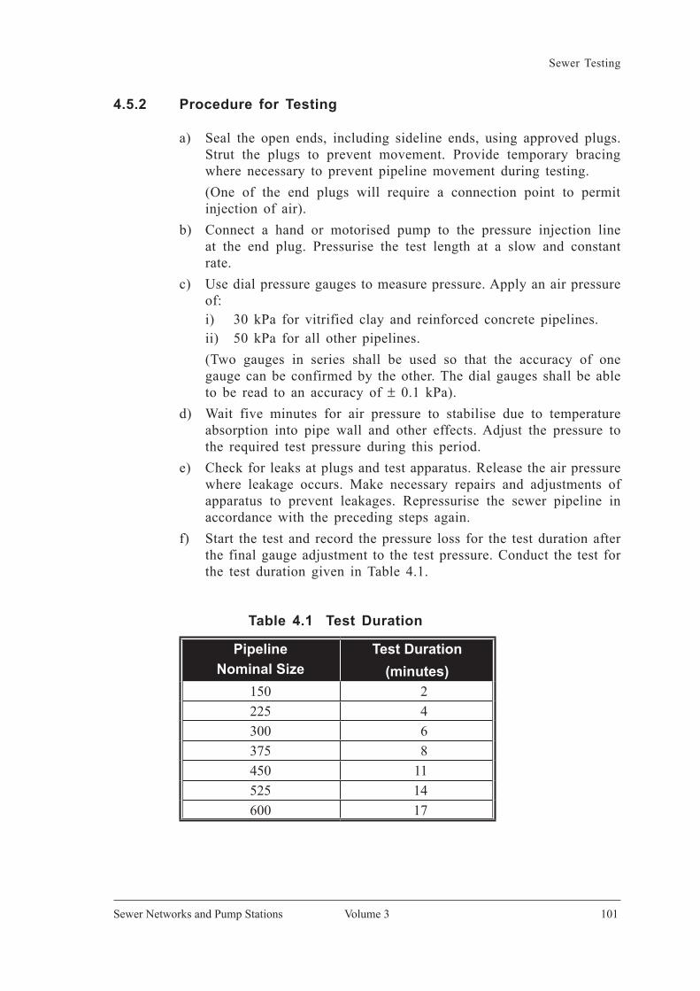
Sewer Testing
Volume 3 101Sewer Networks and Pump Stations
4.5.2 Procedure for Testing
a) Seal the open ends, including sideline ends, using approved plugs. Strut the plugs to prevent movement. Provide temporary bracing where necessary to prevent pipeline movement during testing.
(One of the end plugs will require a connection point to permit injection of air).
b) Connect a hand or motorised pump to the pressure injection line at the end plug. Pressurise the test length at a slow and constant rate.
c) Use dial pressure gauges to measure pressure. Apply an air pressure of:
i) 30 kPa for vitrified clay and reinforced concrete pipelines. ii) 50 kPa for all other pipelines. (Two gauges in series shall be used so that the accuracy of one
gauge can be confirmed by the other. The dial gauges shall be able to be read to an accuracy of ± 0.1 kPa).
d) Wait five minutes for air pressure to stabilise due to temperature absorption into pipe wall and other effects. Adjust the pressure to the required test pressure during this period.
e) Check for leaks at plugs and test apparatus. Release the air pressure where leakage occurs. Make necessary repairs and adjustments of apparatus to prevent leakages. Repressurise the sewer pipeline in accordance with the preceding steps again.
f) Start the test and record the pressure loss for the test duration after the final gauge adjustment to the test pressure. Conduct the test for the test duration given in Table 4.1.
Table 4.1 Test Duration
PipelineNominal Size
Test Duration(minutes)
150 2225 4300 6375 8450 11525 14600 17

Volume 3
Sewer Testing
Malaysian SewerageIndustry Guidelines
102
g) Pass the test if the pressure loss over the test duration does not exceed:
i) 7 kPa for vitrified clay and reinforced concrete pipes ii) 2 kPa for all other pipes
4.5.3 Procedures for Handling Air Test Failure
I) Before Backfill
a) Readjust the pipe pressure to the specified test pressure and examine for leakage by pouring a solution of soft soap and water over the exposed joints if the test fail.
b) Repair leaks and repeat testing where leaks are found at joints. c) Where leaks are not found at joints, move the plug, the one that is
not used to exert air pressure, along the pipeline to isolate lengths with leakage. Uncover pipe barrels in the isolated lengths where leakage in pipe barrels is suspected. Replace leaking pipe lengths and repeat testing.
d) Conduct low pressure water testing to verify that the air test was not erroneous where the test length fails the air test but no source of leakage can be identified.
II) After Backfilling
a) Move the plug up from the other end along the sewer pipeline to isolate the lengths that fail the air test.
b) Exhume the failed length of pipeline and replace pipe lengths. c) Repeat the air test. d) Conduct water testing to check that the air test was not erroneous
when failed lengths could not be isolated using the air test. e) Use CCTV, when required or available, to identify the leakage if
the fail section can not be isolated by the air test or water test.
4.6 Low Pressure Water Test
4.6.1 General
The low pressure water test is commonly used for checking the water-tightness of the joints and the integrity of the sewer pipes. Unlike the high pressure water test, this test can not be used to check the mechanical strength of the sewer pipe. Compared with low pressure air test, this test requires more time to set up the test. Also, the water used for the test

Sewer Testing
Volume 3 103Sewer Networks and Pump Stations
require disposal in an appropriate manner. However, this test will show the location of the leaks more clearly than the low pressure air test.
4.6.2 Procedure
a) Seal the open ends, including sideline ends, using approved plugs. Strut the plugs to prevent movement. Provide temporary bracing where necessary to prevent sewer movement during testing.
b) Establish appropriate arrangements involving a standpipe to apply the water head at the upstream end.
Acceptable arrangements include: i) temporarily fitting a 90° bend to the upstream end, which should
then be connected with a vertical riser of straight pipe to used as a standpipe.
ii) sealing the upstream end with a plug which has a connection point for a hose, which can be connected to a tube acting as a standpipe.
d) Fill in water from the upstream end. Ensure water head is not less than 2 m above pipe crown at the upstream end and not greater than 7 m above pipe crown at the downstream end. Shorten the test length if the sewer gradient is so steep as to cause these water head requirements not to be met.
e) Fill the sewer slowly to the required head and bleed air from behind the upstream plugs.
(Air may be released by slightly loosening the plug and pushing in a piece of wire between the seal and the pipe.)
f) Maintain the water head for two hours. Top up the water as required.
g) Check for leakage at the plugs and the test apparatus during the pressurising period and the constant pressure holding period. Release the water pressure if leakage occurs. Make the necessary repairs and adjustments before repressurising again.
h) Commence the test immediately after the last adjustment of water head in the preceding two hours period.
i) Add water to maintain the starting water head every 5 minutes during the test period of 30 minutes. Record the total amount of water required for readjustment.
j) Pass the water test if: i) the loss of water does not exceed 1 litre per hour per linear
metre per metre internal diameter for vitrified clay and reinforced concrete pipes.

Volume 3
Sewer Testing
Malaysian SewerageIndustry Guidelines
104
ii) there is no loss of water for pipe other than vitrified clay and reinforced concrete pipe.
iii) these is no visible leakage at the joints for all pipe types.
4.6.3 Handling Water Test Failures
I) Before Backfill
a) Readjust the internal water head to the specified test head if the test section fails the water test. Examine visually for leakage at the external surface of joints.
b) Uncover pipe barrels and inspect for leakage if leakage is not evident at joints. Drain the water and move the downstream plug towards upstream, where necessary, to isolate pipe lengths that fail the water test.
c) Repair or replace pipes before repeating the low pressure water test until the sewer passes the test.
II) After Backfill
a) Isolate pipe lengths that fail the water test by moving the downstream plug towards the upstream end in sections when the test sewer fails the water test. Alternatively, conduct a CCTV inspection, where required, to identify the source of leakage if the source of leakage can not be isolated.
b) Exhume failed pipe lengths and replace. c) Repeat test until the sewer pipeline passes the test.
4.7 High Pressure Water Test
4.7.1 General
High pressure water test is normally used for testing the pressure sewers and pipeworks within the pump station. The main aims of the test are to ensure the mechanical stability of the pipe and joints can withstand the working pressure. Since the test is conducted under high pressure, the anchorage of the sewer is more critical than the low pressure tests. Preferably, the test should be conducted before backfill. During the test, the test pumps should not be subjected to hydrostatic pressure.
4.7.2 Procedure
a) Seal the sewer pipeline ends using “test-end” units consisting of short lengths of pipe permanently fitted with caps or valves. Connected the

Sewer Testing
Volume 3 105Sewer Networks and Pump Stations
“test-end” units to the test pipe section using a standard coupling, which permits easy removal of “test-end” units after testing.
(The “test-end” units should have a valve with pressure gauge to allow filling of the test length with water or for venting air. The gauge shall be a conventional circular gauge not less than 200 mm diameter and shall be able to read to an accuracy of ± 0.01 Mpa.)
b) For sewer on level grade, fit tees along the test length, where necessary, to ensure all the air can escape. Fit air valves to such tees. Remove air valves and blank off tees after the test is applied.
c) Fit the test pressure gauge at the lowest end of the test length. (This prevents the test pressure from exceeding the permitted maximum
pressure in the test length.) d) Place pre-constructed temporary thrust blocks behind the test end
units to brace against thrust from the test pressures. (No temporary bracing is permitted along the sewer pipeline. All
specified thrust blocks must be constructed and left to cure before testing.)
e) Fill the test length slowly with water through the valve at the lowest test-end unit.
(The water shall be of fair quality and free from sediment. A firm foam swab placed ahead of the water column will improve the expulsion of air.)
f) Set all valves at high spots to vent air. g) Close the air vents after thorough venting of all air. h) Fill the test length with water. Leave the filled test length undisturbed
for 24 hours prior to testing to allow for absorption of water into the pipes and /or jointing materials.
i) Wipe the exposed fittings and joints clean and dry and check for leakage and other irregularities during this preparatory period. Check also the test pipe for any appreciable movement and disturbance of anchorages. Drain the water and repair any damage found. Repeat the water filling again to start the test.
j) Pump more water into the test length to raise the pressure. Raise the pressure slowly in increments of 1 bars, with pauses of one minute between each increment until achieving the lower of:
i) the maximum rated pressure of the pipes laid, or ii) 1.5 times the design operating pressure of the pipeline (includes
surge allowance) k) Stop the test immediately should any appreciable drop in pressure
be noted during one of these pauses. Determine the cause of the pressure drop. Drain the test length where repairs are required. Start the test again after repairing.

Volume 3
Sewer Testing
Malaysian SewerageIndustry Guidelines
106
l) Pass the pressure test if there is no reduction from the test pressure in the next 10 minutes after the test pressure is conducted. Do not reduce the pressure as the high pressure leakage test should be conducted immediately after this.
4.8 High Pressure Leakage Test
4.8.1 General
High pressure leakage test normally follows the high pressure water test immediately. This is to avoid any unnecessary pressurising and water filling, which could take time and is costly. The purpose of this test is to ensure the pipe and joint will remain intact under the pressure environment.
4.8.2 Procedure
a) Conduct the test immediately after the high pressure water test. Maintain the following test pressures (whichever is lower) for 24 hours by pumping in make-up water if necessary:
i) The maximum rated pressure of the pipes laid, or ii) 1.5 times the design operating pressure of the pipeline (includes
surge allowance). b) Measure the amount of make-up water pumped into the pipe to
maintain the test pressure. c) Pass the test if the measured amount of make-up water does not
exceed 0.1 litre per millimetre of pipe diameter per kilometre of pipe per day for each 3 bars of pressure applied.
d) Reset the test pressure and check all visible joints to locate leakage when the test length fails the test.
4.9 Test for Straightness, Obstruction and Gradient
The sewers shall be check for straightness, obstruction and gradient whenever possible. For gravity sewers and force mains, the gradient and straightness are important to achieve the designed velocity. The following tests are recommended for testing the laid sewer:
I) Test for freedom from obstruction:
a) Visual inspection b) Insertion of mandrel c) CCTV inspection

Sewer Testing
Volume 3 107Sewer Networks and Pump Stations
It should be noted that the visual inspection is only for checking a short length. Sufficient lighting shall be provided when carrying out the inspection. For checking a long sewer, insertion of a mandrel should be adopted.
II) Test for grade and straightness
a) Laser beams with sighting targets b) Sight rails and boning rods c) CCTV inspection d) lamp and mirrors e) Insertion of a smooth balls
The first three methods will provide a more exact assurance for both the gradient and straightness of sewers, which shall be used whenever possible. The latter two methods will provide a rough idea on whether the sewers are laid in certain gradient or straight, which should be used only for a quick check.
4.10 CCTV Inspection
The following subsections outline details on how the CCTV inspection requirements shall be implemented. These guidelines are also aim to enhance professionalism in line with progress in sewerage field, and promote efficiency and cost effectiveness as well as transparency and accountability in sewerage system development.
4.10.1 Objectives of CCTV Inspection
a) Enable detection of sewer defects such as cracks, deformations, collapse, dislocation and etc. which are not detected by normal means.
b) As a quality assurance measure to ensure sewers and sewer appurtenances are constructed in conformability with approved design, specifications, workmanship as well as materials and fixtures used.
c) As a mean to establish record to enhance accountability and professionalism on quality assurance for sewer construction.
4.10.2 Technical Requirements and References
a) Analysis of defects shall be based on WRc Manual for Sewer Condition Classification Latest Edition.
b) Equipment and test devices to be used are as listed in Section 4.10.3.
c) For sewer with diameter larger than 1050 mm, man-entry CCTV survey mode may be adopted unless it can be demonstrated that

Volume 3
Sewer Testing
Malaysian SewerageIndustry Guidelines
108
the CCTV can be maintained in a stable position on or near the central axis of the sewer and images captured are satisfactory and not distorted.
4.10.3 Equipment Specifications and Test Devices
4.10.3.1 Specifications for CCTV unit’s equipment
a) Solid state colour CCTV camera with pan & rotate features, together with a lighting unit, automatic date/ metre age.
b) A self powered tractor or crawler on which the camera is conveyed along a pipeline under inspection in a stable manner.
c) Calibration chart for various sizes of sewer for the camera used. d) Test device for the CCTV camera using ‘Marconi Resolution Chart
No.1’ or its derivative to demonstrate satisfactory performance of the camera.
e) Test device for the monitor and video recorder to establish the effectiveness and accuracy of the ‘on-site’ monitor and video recorder.
f) The control unit comprises the camera unit, crawler control and screenwriter. This console can be mounted permanently in a vehicle or use as portable system.
g) A video recorder for recording high quality video images. h) A mean of producing still images from the monitor screen. i) A PC-based site reporting system capable of producing reports
customised to the Contractor’s needs and to include photographs captured directly from video.
4.10.3.2 Software Requirements
Software standardisation using databank software that can produce report based on WRc format.
4.10.3.3 Report Format
Report in VCD or other digital form to be submitted in MPEG format with minimum 352 x 240 pixels. Two copies of digital records and one copy of hardcopy report shall be forwarded to the Commission.
For the diameter pipe greater than 600 mm, it shall have zooming capabilities.
4.10.4 CCTV Inspection Requirements
The following areas are identified as the minimum coverage for CCTV inspection.

Sewer Testing
Volume 3 109Sewer Networks and Pump Stations
4.10.4.1 High Risk Areas
A 100% CCTV inspection shall be conducted for sewers laid in the ground with high risk of failure and having the following characteristics:
a) Average depth of 6 m or more b) Pipe diameter above 600 mm. c) Areas that have restricted vehicular access for repair (e.g. central
business district). d) Crossings under buildings, lakes, rivers, roads and railway including
their reserve. e) Ground slopes greater than 30o inclination. f) All sewers installed using pipe jacking method. g) All diversion or re-alignment of existing sewer networks. h) All single private developments (with PE > 30), connecting to existing
main sewer.
4.10.4.2 General Inspection Coverage (for Sewer, Manholes and Lateral Connections)
a) Initial CCTV testing & inspection shall be conducted for a minimum 10% random selection of sewers including all manholes and lateral property connections in accordance with standard procedure.
b) If the mandatory requirement of Clause 4.10.4.1 is less than 5% of the entire development area, the minimum CCTV testing & inspection is 10% as in Clause 4.10.4.2a. If the mandatory requirements of Clause 4.10.4.1 is more than 5%, the minimum CCTV testing & inspection shall have an additional of 10%.
c) Prior to taking over existing network that has been approved from any owner or after rehabilitation works have been completed.
d) All new network undergoing intermediate inspection except: i) single phase development with total sewer length less than
500 m long with no interval. ii) vacuum sewer.
4.10.4.3 Stage of Inspection
a) Stage 1- All projects are to start with Stage 1 inspection where 10 % (by length) of sewer network and property connections involved, shall be randomly selected and CCTV inspected.
b) Stage 2 - Should any Grade 3,4 or 5 conditions as defined in the Manual for Sewer Condition Classification approve by the Commission, found in Stage 1 inspection, the CCTV inspection shall proceed to

Volume 3
Sewer Testing
Malaysian SewerageIndustry Guidelines
110
Stage 2 inspection. Stage 2 inspections shall include another 40% of the sewer network to be randomly selected for CCTV inspection.
c) Stage 3- Should any Grade 3,4 or 5 conditions as defined in the Manual for Sewer condition classification approved by the Commission found in Stage 2 inspection, the CCTV inspection shall proceed to Stage 3 where by all the remaining network shall under go CCTV inspection.
4.10.5 CCTV Inspection Implementation Procedure for New Sewer Network
4.10.5.1 Activities to be Completed Before Submitting for Final Intermediate Inspection
a) All construction works have been completed and tested by the supervising qualified person.
b) Sewer networks have been cleared of debris and are ready for inspection.
c) A CCTV Inspection Contractor licensed with the Commission has been appointed to carry out the inspection.
4.10.5.2 Random Selection of Sewer to be Inspected
a) The list of sewer segments and house connections selected for CCTV inspection shall be recorded and the parties witnessing the selection process shall duly sign the record.
b) Names and designations of all persons involved in the random selection process as well as the time, date and place where the selection were carried out shall be recorded in the report on the random selection process. Record of the sewer segments randomly selected for CCTV inspection shall be included as appendix in the report.
c) The random selection process shall be completed in a single session.
4.10.5.3 CCTV Inspection on Site
a) The CCTV inspection shall be carried out 7 days after notice issued by the Commission.
b) Inspection shall be carried out within 24 hours after random selection has been completed.
c) Once started, CCTV inspection for a project shall be carried out without any break. Should for any reason a break/delay of more than 24 hours become necessary, the random selection process shall be repeated to select the remaining sewer segments for the inspection. Reasons for the break/delay shall be recorded.
Sewer Testing
Volume 3 111Sewer Networks and Pump Stations
d) Representative from the Commission or authorized person, consultant representative and contractor responsible for the construction of the sewer shall be present at the onset of CCTV inspection at each project site.
4.10.5.4 Documentation on CCTV Recording
a) At the start of the CCTV recording, the following details must be recorded:
i) Date and starting time of inspection. ii) Project name and location. iii) Names and designation of persons involved (i.e representative of
the Commission or authorized person, consultant & contractor and CCTV contractor).
b) At the beginning of each CCTV recording, every segment of sewer shall be marked with their respective code number with chainage together with the date, start and end times of the recording.
c) After the CCTV inspection and recording have been completed for a project, a copy of recorded CCTV shall be handed over to the Commission or authorized person immediately. Report on the CCTV inspection together with the recording and recommendations shall be prepared by the CCTV contractor and submitted to the relevant Commission regional office or the appointed agency not more than 7 days after the date of inspection. The format of reporting shall follow the standard that had been given (Appendix C). The copy of the tape (or other recording media used to store the record) containing the CCTV inspection records shall be submitted to the Commission regional office or the appointed agency together with a certificate duly signed by the qualified person responsible for the CCTV inspection declaring the authenticity of the recording submitted and that the CCTV inspection has been done in accordance with the procedure stated in this guideline.
4.10.6 Interpretation of Results from CCTV Inspection
a) Classification : Grade 1 to Grade 5 as per the Commission approved Sewer Assessment Classification. The defect grade description shall follow the following colour code:
i) Grade 1: Green ii) Grade 2 : Blue iii) Grade 3 : Orange iv) Grade 4 : Brown v) Grade 5 : Red

Volume 3
Sewer Testing
Malaysian SewerageIndustry Guidelines
112
b) Grade 1 and 2 is acceptable constructional defects but may have other minor defects. It can be accepted provided a performance bond has been submitted and the contractor undertake to rectify the defect within 30 days.
c) Sewer with Grade 3, 4 or 5 conditions has major structural defects and shall not be accepted. Relaid of the affected sewer segments is necessary.
4.10.7 Follow Up Action to Be Taken
a) For Grade 1 and Grade 2, the developer shall rectify and make good to all the defects in 30 days. These rectification works shall be witnessed by the parties concerned and agreed together that the works had been completed. The Commission or the authorised person may instruct CCTV inspection to be carried out again. Under these grade classifications, the letter of recommendation for CFO will be released by the Commission or the authorised agency.
b) For Grade 3, 4 or 5 classifications, the developer shall change, replace, relay or reconstruct the rejected works. Further CCTV inspection shall be carried out before acceptance. The letter of support for CFO will be released upon acceptance.
c) In the events of any blockages, damages, seepages and etc to the sewer networks during the defects liability period, the Commission may require the developer to carry out further CCTV inspection to determine the cause and extent of the problems that arises. CCTV inspection shall be carried out immediately within 24 hours.
Table 4.2 provides the description of various defect grades
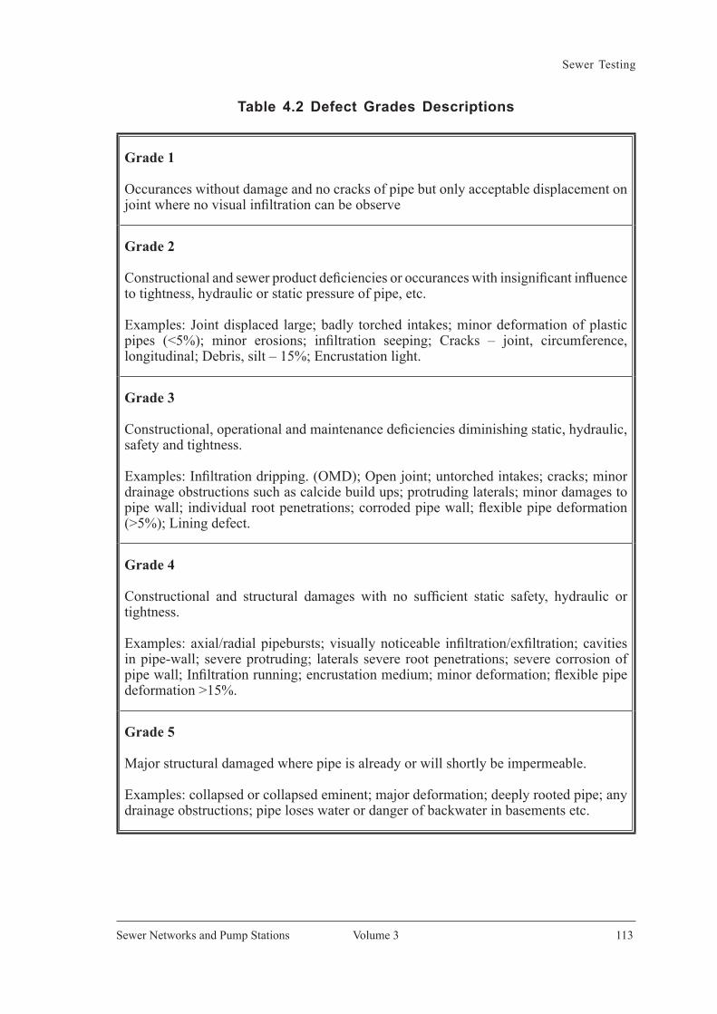
Sewer Testing
Volume 3 113Sewer Networks and Pump Stations
Table 4.2 Defect Grades Descriptions
Grade 1
Occurances without damage and no cracks of pipe but only acceptable displacement on joint where no visual infiltration can be observe
Grade 2
Constructional and sewer product deficiencies or occurances with insignificant influence to tightness, hydraulic or static pressure of pipe, etc.
Examples: Joint displaced large; badly torched intakes; minor deformation of plastic pipes (<5%); minor erosions; infiltration seeping; Cracks – joint, circumference, longitudinal; Debris, silt – 15%; Encrustation light.
Grade 3
Constructional, operational and maintenance deficiencies diminishing static, hydraulic, safety and tightness.
Examples: Infiltration dripping. (OMD); Open joint; untorched intakes; cracks; minor drainage obstructions such as calcide build ups; protruding laterals; minor damages to pipe wall; individual root penetrations; corroded pipe wall; flexible pipe deformation (>5%); Lining defect.
Grade 4
Constructional and structural damages with no sufficient static safety, hydraulic or tightness.
Examples: axial/radial pipebursts; visually noticeable infiltration/exfiltration; cavities in pipe-wall; severe protruding; laterals severe root penetrations; severe corrosion of pipe wall; Infiltration running; encrustation medium; minor deformation; flexible pipe deformation >15%.
Grade 5
Major structural damaged where pipe is already or will shortly be impermeable.
Examples: collapsed or collapsed eminent; major deformation; deeply rooted pipe; any drainage obstructions; pipe loses water or danger of backwater in basements etc.

Volume 3
Sewer Testing
Malaysian SewerageIndustry Guidelines
114
4.11 Infiltration Test
4.11.1 General
Infiltration is an extraneous flow not contributed from households. Although design has allowed for certain amount of infiltration, a significant amount of unexpected infiltration will overload both the collection sewers and the sewage treatment plant. To avoid any extra infiltration, a test maybe conducted on the gravity sewer laid. If the force main is significantly below the groundwater table, an infiltration test is also highly recommended. When severe infiltration is found during sewer laying, the source shall be investigated immediately.
Infiltration test is normally conducted after backfill and after the groundwater level has stabilised. The procedures are as follows:
4.11.2 Procedure
a) Plug the inlets at all upstream open ends, after the groundwater level has stabilised following backfilling.
b) Measure any infiltration from the sewer to the manhole or within manhole itself.
c) Conduct the measurement of infiltration for at least 24 hours. d) Pass the infiltration test if the infiltration does not exceed 1 litre
per hour per metre diameter per meter of pipe run.
4.11.3 Handling Test Failures
a) Conduct a light and mirror test to identify the location of the infiltration if the pipe is small and short.
b) Move an inflated rubber plug toward downstream end to isolate lengths of leakage. Repeat the test procedure after each plug relocation
c) Conduct a CCTV inspection if the location of the infiltration can not be identified by the light and mirror test or by the movement of the inflated rubber plug.
d) Exhume and repair the fail section of the pipe.
4.12 Watertightness Test
4.12.1 General
Visual inspection is usually sufficient to ensure the watertightness of manhole and other ancillary structures. However, watertightness test may be required if:

Sewer Testing
Volume 3 115Sewer Networks and Pump Stations
a) Instruction from the authorised inspection person. b) Unsatisfactory features identified from the visual inspection. c) Suspicion of poor workmanship or poor materials. d) Leakages revealed from other tests. e) Frequent surcharging of the structure is possible.
The test should be carried out only after the structures have achieved sufficient strength to withstand the test pressure. Where possible, the test shall be carried out before backfilled or concrete surrounded.
For manhole less than 1.5 m in depth, the manhole shall be filled with
clean water to the bottom of cover. For manhole more than 1.5 m in depth, the water head for the test shall not be less than 1.5 m or the mean groundwater level, whichever is larger. For any other ancillary structure, the water shall be filled to the top of the structure unless otherwise specified by the authorised inspection person.
The procedures for testing the manhole are listed below. For other ancillary structures, the procedures can still be adopted. However, the height which the water level should be tested shall follow the instruction from the authorised inspection person.
4.12.2 Procedures
a) Fit a plug or stopper in all the openings. b) Secure the plug/stopper to resist the full test pressure. c) Provide a mean to remove the plug/stopper from the ground level
safely if test water is allowed to be discharged to the downstream. (The plug/stopper may need to be remove while the structure is still
full of water. Alternatively, a potable submersible pump might be sunk into the test structure to remove the water.)
d) Fill the structure with clean water. Fill slowly to avoid any intense pressure impact from the water.
e) Observe visually to identify any water leakage to the outside of the structure. Drain the water to repair the leakage if necessary.
f) Otherwise, allow the water to stay in the test structure for 8 hours. Investigate any appreciable water loss.
g) Drain and dispose of the test water from the test structure in an appropriate manner and to a suitable location.


Appendix A


Appendix A
Volume 3 119Sewer Networks and Pump Stations
Figure A 1 : Standard Manhole Cover
CLASS D400 "MARKING " EN 124
Y
YSTAINLESS STEELBOLT AND NUT10mm Ø, 100mmLONG
HOLE
10mm Ø STAINLESS
SECTION Y - Y : TYPICAL HINGE
STEEL BOLT
SECTION Y - Y : COVER HINGE OPEN AT 90° SECTION Y - Y : COVER HINGE OPEN AT MIN. 100°
B B
C
C
PRECAST R.C. MANHOLE
SECTION B - B
PLAN
DETAIL '1'
Z
Z
DETAIL '4' : EMBOSSED LOGO
ALL CORNERS
DETAIL '2' & '3' : EMBOSSED DESIGN
3mm ± 0.5
TO BE ROUNDED OFF
BAHAYARUANG TERKURUNG
DILARANG MASUK
DANGERCONFINED SPACE
DO NOT ENTER
MODEL NO. AND THE
SEE DETAIL '1'
EMBOSSED LOGO(SEE DETAIL '4')
LOCKING AND
PLACE OF MANUFACTUREMANUFACTURER'S NAME AND
SERIAL NO.
AA
SEE DETAIL '3'
SEE DETAIL '2'
LIFTING DEVICE
HINGE DEVICE
16mm Ø BOLT
SECTION X - X : TYPICAL LOCKING DEVICE
( TYPICAL SURFACE DETAIL )
SECTION Z - Z
TYPICAL SECTION OF HEAVY DUTYD.I. MANHOLE COVER AND FRAME
SECTION A - A
TYPICAL DETAILS OF HEAVY DUTYD.I. MANHOLE COVER AND FRAME
PRECAST R.C. MANHOLE
SECTION C - C
ANCHORING DEVICE WITH12mm Ø THREAD AND 16mm Ø HOLE (ANCHORDEPTH : 50mm)
FILLED WITH NON-SHRINKCEMENTITIOUS MATERIAL / PREMIX
FILLED WITH NON-SHRINKCEMENTITIOUS MATERIAL / PREMIX
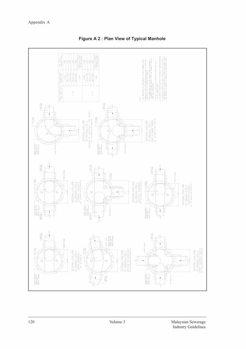
Volume 3
Appendix A
Malaysian SewerageIndustry Guidelines
120
Figure A 2 : Plan View of Typical Manhole

Appendix A
Volume 3 121Sewer Networks and Pump Stations
Figure A 3 Typical Shallow Precast Concrete Manhole (Ground Level to Invert of Pipe 1.2 m ≤ Depth < 2.5 m)
Figure A 3 : Typical Shallow Precast Concrete Manhole
(Ground Level to Invert of Pipe 1.2m ≤ Depth < 2.5m
Figure A 3 : Typical Shallow Precast Concrete Manhole (Ground Level to Invert of Pipe 1.2 m ≤ Depth < 2.5 m)

Volume 3
Appendix A
Malaysian SewerageIndustry Guidelines
122
Figure A 4 Typical Shallow Precast Concrete Manhole with Backdrop(Ground Level to Invert of Pipe 1.2 m ≤ Depth < 2.5 m)
Figure A 4 : Typical Shallow Precast Concrete Manhole with Backdrop (Ground Level to Invert of Pipe 1.2m ≤ Depth < 2.5m)
>
≥

Appendix A
Volume 3 123Sewer Networks and Pump Stations
Figure A 5 Typical Medium Precast Concrete Manhole (Ground Level to Invert of Pipe 2.5 m ≤ Depth < 5 m)
Figure A 5 : Typical Medium Precast Concrete Manhole (Ground Level to Invert of Pipe 2.5m ≤ Depth < 5m)

Volume 3
Appendix A
Malaysian SewerageIndustry Guidelines
124
Figure A 6 Typical Medium Precast Concrete Manhole with backdrop(Ground Level to Invert of Pipe 2.5 m ≤ Depth < 5 m)
Figure A 6 : Typical Medium Precast Concrete Manhole with Backdrop (Ground Level to Invert of Pipe 2.5m ≤ Depth < 5m)
>
≥

Appendix A
Volume 3 125Sewer Networks and Pump Stations
Figure A 7 Typical Deep Precast Concrete Manhole(Ground Level to Invert of Pipe 5 m ≤ Depth ≤ 9 m)
Figure A 7 : Typical Deep Precast Concrete Manhole (Ground Level to Invert of Pipe 5m ≤ Depth ≤ 9m)

Volume 3
Appendix A
Malaysian SewerageIndustry Guidelines
126
Figure A8 Typical Deep Precast Concrete Manhole with Backdrop(Ground Level to Invert of Pipe 5 m ≤ Depth ≤ 9 m)
Figure A 8 : Typical Deep Precast Concrete Manhole with Backdrop (Ground Level to Invert of Pipe 5m ≤ Depth ≤ 9m)
>
≥

Appendix A
Volume 3 127Sewer Networks and Pump Stations
Figure A 9 : Typical Details of Large Diameter Manhole (LDM) Type
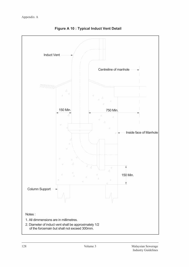
Volume 3
Appendix A
Malaysian SewerageIndustry Guidelines
128
Figure A 10 : Typical Induct Vent Detail
Induct Vent
1. All dimmensions are in millimetres.
150 Min.
Inside face of Manhole
750 Min.150 Min.
Column Support
Centreline of manhole
Notes :
2. Diameter of induct vent shall be approximately 1/2 of the forcemain but shall not exceed 300mm.

Appendix A
Volume 3 129Sewer Networks and Pump Stations
Figure A 11 : Details of Household Connection to Main Sewer Reticulation Pipe for V.C. Pipe
VARIES

Volume 3
Appendix A
Malaysian SewerageIndustry Guidelines
130
Figure A 12 : Typical Details of Concrete Thrust and Anchor Block
¼°
½°
° °
¼°
½°° ° °

Appendix A
Volume 3 131Sewer Networks and Pump Stations
Figure A 13(a) : Typical Details of Inverted Siphons or Depressed Sewer
Figure A 13a : Typical Details of Inverted Siphons or Depressed Sewer

Volume 3
Appendix A
Malaysian SewerageIndustry Guidelines
132
Figure A 13(b) : Typical Details of Inverted Siphons or Depressed Sewer
Figure A 13b : Typical Details of Inverted Siphons or Depressed Sewer

Appendix A
Volume 3 133Sewer Networks and Pump Stations
Figure A 14(a) : Typical Details for Force Main – Scour Valve and ReceivingManhole
Figure A 14a : Typical Details for Force Main – Scour Valve and Receiving Manhole

Volume 3
Appendix A
Malaysian SewerageIndustry Guidelines
134
Figure A 14(b) : Typical Details for Force Main – Air ValveFigure A 14b : Typical Details for Force Main – Air Valve

Appendix A
Volume 3 135Sewer Networks and Pump Stations
Figure A 15 : Typical Detail of Force Main Crossing

Volume 3
Appendix A
Malaysian SewerageIndustry Guidelines
136
Figure A 16(a) : Standard Pipe BeddingsFigure A 16a : Standard Pipe Beddings

Appendix A
Volume 3 137Sewer Networks and Pump Stations
Figure A 16(b) : Standard Pipe Beddings
Figure A 16b : Standard Pipe Beddings

Volume 3
Appendix A
Malaysian SewerageIndustry Guidelines
138
Figure A 17 : Vacuum Sewage Collection System
Figure A 18 : House Connection
vacuum sewer
vacuum station
sewage treatment works
gravity lateral sewer
collection chamber
crossover pipevacuum sewer

Appendix A
Volume 3 139Sewer Networks and Pump Stations
Figure A 19 (a) : Example Of Vacuum Station With Housed Collection Vessel
was
hdow
n su
mp
inco
min
g se
wer
m
ains
serv
ice
plat
form
forc
e m
ain
biof
ilter
non-
retu
rn v
alve
disc
harg
e pu
mps
serv
ice
plat
form
sigh
t gla
ss
toile
t
fire-
fight
ing
syst
em
AM
F bo
ard
vacu
um p
umps
hand
rail
vacu
um g
auge
s
cont
rol p
anel
/te
lem
etry
sys
tem
char
t rec
orde
r
stan
dby
dies
el
gene
rato
r
fuel
tank
PLA
N
up
moi
stur
e tra
p
suct
ion
pipe
from
w
ashd
own
sum
p

Volume 3
Appendix A
Malaysian SewerageIndustry Guidelines
140
Figure A 19 (b) : Example Of Vacuum Station With Housed Collection Vessel
bypa
ss
conn
ectio
n
vacu
um ta
ke-o
ff pi
peto
vac
uum
pum
ps
moi
stur
e tra
p
AB
S p
ipew
ork
tova
cuum
pum
ps
ABS
suc
tion
pipe
vacu
um p
ump
ABS
vac
uum
exh
aust
pi
pew
ork
to b
iofil
ter
moi
stur
e tra
pdr
aina
ge p
ipe
cast
in-s
itupl
inth
biof
ilter
med
ia
vacu
um v
esse
l
disc
harg
epu
mps
ELE
VATI
ON

Appendix A
Volume 3 141Sewer Networks and Pump Stations
Figure A 20 (a) : Collection Chambers With Interface Valves Vented Through Breather Pipes
Figure A. 20 (b) : Collection Chamber With Interface Valve Activated By Float
interface valve
150mm thick concrete surround
chamber ring with base and conical benching
hingged D.I. manhole cover
heavy duty cover slab
float
landing slab
chamber ring
to vacuum sewer
suction pipe
valve controller
150mm thick concrete surround
sensor pipe
chamber ring with base and conical benching
hingged D.I. manhole cover
heavy duty cover slab
fall
breather pipe
landing slab
chamber ring
to vacuum sewer
gravity lateral swer
suction pipe
interface valve
sensor pipe
heavy duty cover slab
fall
breather pipe
landing slab
chamber ring
to vacuum sewer
suction pipe
interface valve
gravity lateral sewer
150mm thick concrete surround
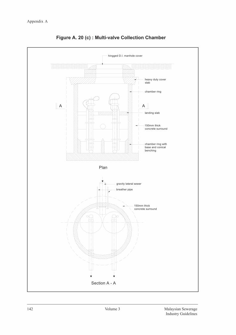
Volume 3
Appendix A
Malaysian SewerageIndustry Guidelines
142
Figure A. 20 (c) : Multi-valve Collection Chamber
A A
150mm thick concrete surround
150mm thick concrete surround
gravity lateral sewer
breather pipe
Section A - A
Plan
chamber ring with base and conical benching
hingged D.I. manhole cover
heavy duty cover slab
landing slab
chamber ring

Appendix A
Volume 3 143Sewer Networks and Pump Stations
Figure A 21: Vacuum Sewer Profiles (not to scale)
Figure A. 22 : Example of Vacuum Sewer Profiles For Uphill and Downhill Transport (Not To Scale)
flow150m 150m
300m
m
10m
100-
200m
m
flow
15m 10m 10m15m
L/2
100-
200m
m
flow
L L
L/2 L/2 L/2
0.2% min. slope
0.2% min. slope
flow
6m min.
0.2% min. slopeflow

Volume 3
Appendix A
Malaysian SewerageIndustry Guidelines
144
Figure A 23 : Y-Branch for Vacuum Sewer
Figure A 24 : Method of Joining Crossover Pipes and Branch Sewers to Vacuum Mains
°branch
Direction of flow
vertical angle60
45 elbow
45 elbow
flow
flow
flow
vacuum main
Plan
End View
crossover pipe / branch sewer
flow
flowflow
45 `Y' fitting(may be fabricated)
vacuum main
flow flow
900
mm
min
. cov
er
60 max
°
° 45 elbow°
°
Elevation
ground level

Appendix A
Volume 3 145Sewer Networks and Pump Stations
Figure A 25 : Typical Details of Dry-well Pump Station
BLOCK3 LAYER CONC. VENTILATION
PERFORATED SLAB
DOOR
LIGHTNING ARRESTORCOPPER TYPE
CARRIERLIFTING I-BEAM C/W
WINDOW
GATE VALVE
CHECK VALVE
DRY PIT PUMPSDEWATERING PUMP
SCREENINGS COLLECTION BIN
CHEQUER PLATE
CAT LADDER
WET WELL DRY WELL
(FLOAT SWITCH)
OPENINGS
STOP LOG
INCOMING SEWER
R.C STAIRCASE TO ENGR'S DETAIL
HANDRAIL
HANDRAIL
PENSTOCK
MECHANICAL COARSE SCREEN TO NEAREST SUMPRAIN WATER DOWN PIPE
R.C GUTTER TO ENGR'S DETAIL
BRICKWALL C/W CEMENT PLASTER ON BOTH SIDES
1st. STANDBY PUMP START ALARM
2nd. STANDBY PUMP START
SUMP BWL
ALL PUMP STOP
1st.. DUTY PUMP START
2nd. DUTY PUMP START
RAMP DOWN
DN
G.I
CH
AIN
GU
AR
D.
PLAN VIEW
LOUVRES WINDOWADJUSTABLE GLASS
DOOR
DRY PIT PUMPS
R.C STAIRCASE TO ENGR'S DETAIL124 378 6 5101112 913
SPOT LIGHTCHEQUER PLATE
BRICKWALL C/W CEMENTPLASTER ON BOTH SIDES
AIR EXTRACTOR FAN
3 LAYER CONC. VENTILATION BLOCK
CHECK VALVE.
R.C STAIRCASE TO ENGR'S DETAIL.
BLOCK AT TOP AND BOTTOM LEVELCONCRETE VENTILATION
EXTRACTOR FAN
CONC. THRUST BLOCK.
654321
7
CHAIN GUARD.
181920212223
17
DN
CONC. THRUST BLOCK.
A
GATE VALVE.
1011
9816
131415
12
G.I CHAIN GUARDPENSTOCK
20191714 15 16 18 21
A
INCOMING SEWER
GRATING COVER
FORCEMAIN
3 LAYER CONC. VENTILATIONBLOCK AT TOP AND BOTTOM LEVELLIQUID RETURN FROM OTHER UNIT PROCESSESDRAIN
CONC. APRON LAID TO FALL
MECHANICAL COARSE SCREEN
OVERFLOW CHAMBER
WP
OVERFLOW PIPE DISCHARGETO MONSOON DRAIN
AT TOP AND BOTTOMLEVEL
SECTION VIEW
N.B. : The discharge level for dewatering pump shall be higher than the invert level of overflow pipe to prevent sewage from back flowing into the dry well during flooding

Volume 3
Appendix A
Malaysian SewerageIndustry Guidelines
146
Figure A 26 : Typical Detail of Wet-well Pump Station

Appendix A
Volume 3 147Sewer Networks and Pump Stations
Figure A 27 : Buffer Zone for Pump Station with Super Structure
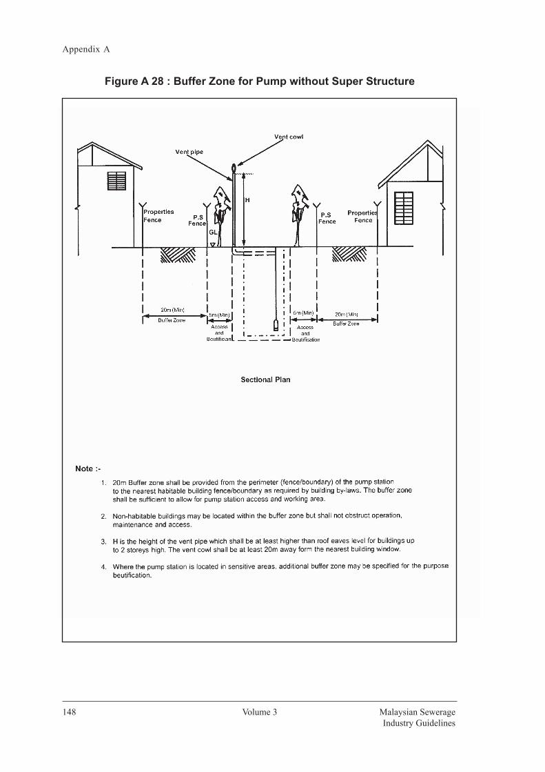
Volume 3
Appendix A
Malaysian SewerageIndustry Guidelines
148
Figure A 28 : Buffer Zone for Pump without Super Structure

Appendix A
Volume 3 149Sewer Networks and Pump Stations
Figure A 29 : Standards Symbols and Abbreviations
Figure A. 29 : Symbols
BUILDING (WOODEN OR
BUILDING (MASONRY)
GATE
POND
FIRE
PAVED
RAIL ROAD
CULVER
BRIDGE
PAVED CHANNEL AND FLOW
UNPAVED SIDE SLOPESCHAINLINK FENCEUTILITY
TELEPHONE POLE
ELECTRIC
STREET
PROPERTY, LOT OR RESERVE
SEPTIC TANKBOREHOL
PON
H
LIGHT SIDE POLE SIDE
ST
Symbols
PROVISION FOR BACKDROP FOR SEWER CONNECTIONPROVISION FOR T-JOINT FOR SEWER CONNECTION
PROPOSED MANHOLE AND SEWER IN PLAN
PROPOSED MANHOLE AND SEWER IN PROFILE
EXISTING MANHOLE AND SEWER IN PLAN
EXISTING MANHOLE AND SEWER IN PROFILE
WATER MAIN (GENERALLY 1m DEEP)
ELECTRICAL TRANSMISSION LINE OR CONDUIT (GENERALLY 1m DEEP)
TELEPHONE CONDUIT (GENERALLY 1.5m DEEP)
W
E
T
DN 375 R.C.P DN 375 R.C.P
1:80 1:72DIRECTION OF
SEW ER
PIPE
G GAS
Abbreviations
ASBESTOS CEMENT CAST
A.C.P. C.I.
CONCRET
DUCTILE DIAMETE
CENTRECONC. D.I. DIA.(ø) CRS
DRAWINEXISTINGROUND GRADE HORIZONTA
INVERJALAN KAMPUNLORONLEFT MAXIMUMANHOLMINIMUMODIFIENUMBE
HIGH
INSIDE
DRG. EXIST. GD. GR. HORZ INV. JLN. KG. LRG. LT MAX. M.H. MIN. MOD. NO.
H.A. I.D. VERT.
N.T.S.O.D.
R.C.PRET.RTSSG.SHT.SPECSTD.SCW.STL.STA.TYP.VAR.
CH.
V.C.P
R.C.
NOT TO OUTSIDE
REINFORCED CONCRETE RETICULATION RIGHTSLOPESTREAM OR SHEETSPECIFICATIOSTANDARSTANDARD CUT-OUT STEELSTATIOTYPICAVARIEVERTICA
CHAINAG
VITRIFIED CLAY
D.M.H. DROP
REINFORCED CLASS CL. DIAMETEDIA.(ø) NOMINAL DN.
HDPE HIGH DENSITY


Appendix B


Appendix B
Volume 3 153Sewer Networks and Pump Stations
Appendix B
Sewer Networks and Pump Stations Volume 3 Page 127
Table B1 Classes of Rigid Pipe Required for Various Depth
CLA
Y P
IPE
CLA
SSES
OF
RIG
ID P
IPE
RE
QU
IRE
D F
OR
VA
RIO
US
DE
PTH
TAB
LE B
.1


Appendix C

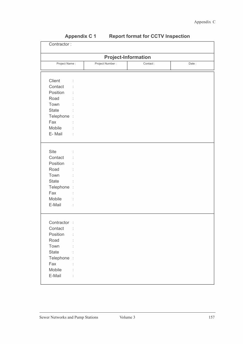
Appendix C
Volume 3 157Sewer Networks and Pump Stations
Appendix C
Sewer Networks and Pump Stations Volume 3 Page 129
Appendix C 1 Report format for CCTV Inspection
Client :
Contact :
Position :
Road :
Town :
State :
Telephone :
Fax :
Mobile :
E- Mail :
Site :
Contact :
Position :
Road :
Town :
State :
Telephone :
Fax :
Mobile :
E-Mail :
Contractor :
Contact :
Position :
Road :
Town :
State :
Telephone :
Fax :
Mobile :
E-Mail :
Contractor :
Project-InformationProject Name : Project Number : Contact : Date :
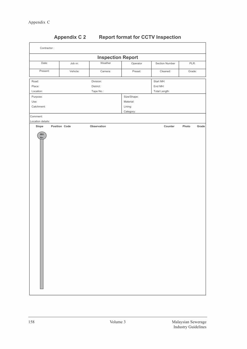
Volume 3
Appendix C
Malaysian SewerageIndustry Guidelines
158
Appendix C
130 Volume 3 Malaysian Sewerage Industry Guidelines
Appendix C 2 Report format for CCTV Inspection
Contractor :
Road: Division: Start MH:
Place: District: End MH:
Location: Tape No.: Total Length:
Purpose: Size/Shape:
Use: Material:
Catchment: Lining:
Category:
Comment:
Location details:
Code Observation Counter Photo GradeSlope
Date:
Preset:
Weather Operator
Present: Camera: Cleaned:
Section Number PLR:
Grade:
Inspection Report
Position
Job nr:
Vehicle:
MH No.

Appendix C
Volume 3 159Sewer Networks and Pump Stations
Appendix C
Sewer Networks and Pump Stations Volume 3 Page 131
Appendix C 3 Report format for CCTV Inspection
Contractor :
Inspection PhotosPLR :Town : Road : Date : Section Nmber :

Volume 3
Appendix C
Malaysian SewerageIndustry Guidelines
160
Appendix C
132 Volume 3 Malaysian Sewerage Industry Guidelines
Appendix C 4 Report format for CCTV Inspection
To M
H :
Pipe
Dia
.Pi
peW
ide
Cra
cks
orSe
ctio
n(m
m)
Leng
th (M
)Se
epin
gD
rippi
ngR
unni
ngJo
ints
Frac
ture
sTo
tal
N.B
:W
hen
mor
e th
an o
ne d
efec
t is
reco
rded
at t
he s
ame
chai
nage
, the
mos
t sev
ere
defe
ct is
cou
nted
.
Prep
ared
By
:Pr
epar
ed B
y :
Appr
oved
By
: ( Q
ualif
ied
Pers
on )
( Nam
e : Q
ualif
ied
Pers
on &
Com
pany
)( N
ame
: Qua
lifie
d Pe
rson
& C
ompa
ny)
Dat
e O
f Rep
ort
:D
ate
Of R
epor
t :
Dat
e
:
Infil
tratio
n
DEFE
CT S
UMM
ARY
OF
PIPE
SEC
TIO
NS IN
SPEC
TIO
N
Item
Star
t MH
End
MH
Mat
eria
lO
ther
sC
omm
ents
From
MH
:

Appendix C
Volume 3 161Sewer Networks and Pump Stations
Appendix C
Sewer Networks and Pump Stations Volume 3 Page 133
Appendix C 5 Report format for CCTV Inspection
From MH : To MH :
Item PositionNo. (M)
DEFECT SUMMARY OF PIPE SECTIONS INSPECTION
Start MH Finish MH Code Description Grade

Volume 3
Appendix C
Malaysian SewerageIndustry Guidelines
162
App
endi
x C
134
Vol
ume
3 M
alay
sian
Sew
erag
e
In
dust
ry G
uide
lines
App
endi
x C
6
Mod
ules
Se
ctio
n 5
- St
ruct
ural
Def
ect
Codi
ng (
Mod
ule
6A)
CC
RA
CK
5.1
FFR
AC
TUR
E5.
7B
BR
OK
EN5.
14H
HO
LE5.
16D
DEF
OR
MED
5.18
XC
OLL
AP
SE
5.22
JJO
INT
5.25
CLLo
ngitu
dina
l5.
2FL
Long
itudi
nal
5.7
BSV
Soil
Visi
ble
Beyo
nd5.
14H
SVSo
il Vi
sibl
e Be
yond
5.16
DV
Def
orm
ed V
ertic
ally
5.
18JO
Join
t O
ffse
t (D
ispl
aced
)5.
25CC
Circ
umfe
rent
ial
5.2
FCCi
rcum
fere
ntia
l5.
7D
efec
tD
efec
t(b
rick)
XPPi
pe C
olla
pse
5.22
JSJo
int
Sepa
rate
d (O
pen)
5.25
CMM
ultip
le5.
2FM
Mul
tiple
5.7
BVV
Vold
Vis
ible
Bey
ond
5.14
HSV
Vold
Vis
ible
Bey
ond
5.16
DH
Def
orm
ed5.
18XB
Bric
k Co
llaps
e5.
22JA
Join
t An
gula
r5.
25CS
Spira
l5.
2FS
Spira
l5.
7D
efec
tD
efec
tH
oriz
onta
lly (
bric
k)
SS
UR
FAC
E5.
30S
SU
RFA
CE
5.30
SS
UR
FAC
E5.
30S
SU
RFA
CE
5.30
SS
UR
FAC
E5.
30S
SU
RFA
CE
5.30
SS
UR
FAC
E D
AM
AG
E5.
30D
AM
AG
ED
AM
AG
ED
AM
AG
ED
AM
AG
ED
AM
AG
ED
AM
AG
ES
RI
Rou
ghn
ess
5.30
SA
VA
ggre
gate
Vis
ible
5.30
SA
PA
ggre
gate
5.
30S
AM
Agg
rega
te
5.30
SR
VR
ein
forc
emen
t5.
30S
RP
Rei
nfo
rcem
ent
5.30
SA
PA
ggre
gate
Pro
ject
ing
5.30
Incr
ease
dSA
VMM
echa
nica
l5.
31P
roje
ctin
gM
issi
ng
Vis
ible
Pro
ject
ing
SRIM
Mec
hani
cal
5.31
SAVC
Chem
ical
Att
ack
5.31
SAPM
Mec
hani
cal
5.31
SAM
MM
echa
nica
l5.
31SR
VMM
echa
nica
l5.
31SR
PMM
echa
nica
l5.
31SA
PMM
echa
nica
l5.
31SR
ICCh
emic
al A
ttac
k5.
31SA
VZN
ot E
vide
nt5.
32SA
PCCh
emic
al A
ttac
k5.
31SA
MC
Chem
ical
Att
ack
5.31
SRVC
Chem
ical
Att
ack
5.31
SRPC
Chem
ical
Att
ack
5.31
SAPC
Chem
ical
Att
ack
5.31
SRIZ
Not
Evi
dent
5.32
SAPZ
Not
Evi
dent
5.32
SAM
ZN
ot E
vide
nt5.
32SR
VZN
ot E
vide
nt5.
32SR
PZN
ot E
vide
nt5.
32SA
PZN
ot E
vide
nt5.
32
SS
UR
FAC
E5.
30S
SU
RFA
CE
5.30
SS
UR
FAC
E5.
30S
SU
RFA
CE
5.30
LFLI
NIN
G F
AIL
UR
E5.
44LF
LIN
ING
FA
ILU
RE
5.44
WF
WEL
D F
AIL
UR
E5.
56D
AM
AG
ED
AM
AG
ED
AM
AG
ED
AM
AG
E(c
onti
nu
e)
SM
VM
issi
ng
Wal
l5.
31S
SS
Su
rfac
e S
palli
ng
5.31
SZ
Oth
er5.
31LF
DD
etac
hed
Lini
ng5.
44LF
OC
Ove
rcut
Ser
vice
5.44
WFL
Long
itudi
nal
5.56
SMW
MM
echa
nica
l5.
31SS
SMM
echa
nica
l5.
31SZ
MM
echa
nica
l5.
31SC
PCo
rros
ion
5.31
LFD
ED
efec
tive
End
5.44
LFU
CU
nder
cut
Serv
ice
5.44
WFG
Circ
umfe
rent
al5.
56SM
WC
Chem
ical
Att
ack
5.31
SSSC
Chem
ical
Att
ack
5.31
SZC
Chem
ical
Att
ack
5.31
(met
al p
ipe)
5.31
LFB
Blis
tere
d Li
ning
5.44
LFB K
Buok
led
Lini
ng5.
44W
FMM
ultip
le5.
56SM
WZ
Not
Evi
dent
5.32
SSSZ
Not
Evi
dent
5.32
SZZ
Not
Evi
dent
5.32
LFCS
Serv
ice
Cut
Shift
ed5.
44LF
WW
rinkl
ed L
inin
g5.
44W
FS
Spira
l5.
56LF
ACAb
ando
ned
5.44
Conn
ectio
nLF
ZO
ther
5.44
WFZ
Uni
dent
ified
5.56
RP
PO
INT
REP
AIR
5.62
RP
PO
INT
REP
AIR
5.62
(
con
tin
ues
)R
PR
Pip
e R
epla
ced
5.62
RP
LLo
caliz
ed P
ipel
ine r
5.62
RPR
DD
efec
tive
5.62
RPL
DD
efec
tive
5.62
RPP
Patc
h Rep
air
5.62
RPZ
Oth
er5.
62SM
WZ
Not
Evi
dent
5.32
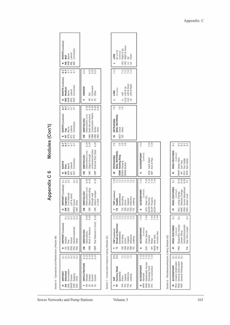
Appendix C
Volume 3 163Sewer Networks and Pump Stations
App
endi
x C
Sew
er N
etw
orks
and
Pum
p St
atio
ns
Vol
ume
3 Pa
ge 1
35
App
endi
x C
6
Mod
ules
(Con
’t)
Sect
ion
6 -
Ope
ratio
nal a
nd M
aint
enan
ce (
Mod
ule
6B)
DD
EPO
SIT
6.1
DD
EPO
SIT
(co
nti
nu
e )D
DEP
OS
IT (
con
tin
ue )
6.1
RR
OO
TS6
.7R
RO
OTS
(co
nti
nu
e )6
.7R
RO
OTS
(co
nti
nu
e )6
.7R
RO
OTS
(co
nti
nu
e )D
AA
ttac
hed
6.1
DS
Sett
led
6.1
DN
Ingr
ess
6.1
RF
Fin
e6
.7R
TTa
p6
.7R
MM
ediu
m6
.7R
BB
all
DAE
Encr
usta
tion
6.2
DSF
Fine
6.2
DN
FFi
ne M
ater
ial
6.3
RFB
Barr
el6.
7R
TBBa
rrel
6.7
RM
BBa
rrel
6.7
RBB
Barr
elD
AGS
Gre
ase
6.2
DSG
Gra
vel
6.2
(silt
& s
and)
RFL
Late
ral
6.7
RT L
Late
ral
6.7
RM
LLa
tera
l6.
7RBL
Late
ral
DAR
Rag
ging
6.
2D
SCH
ard/
Com
pact
ed6.
2D
NG
VG
rave
l6.
3R
FCCo
nnec
tion
6.7
RTC
Conn
ectio
n6.
7R
MC
Conn
ectio
n6.
7R
BCCo
nnec
tion
DAZ
Oth
er6.
2D
SZO
ther
6.2
DN
ZO
ther
6.3
IIN
FILI
TRA
TIO
N6.
13O
BO
BS
TAC
LES
/O
BO
BS
TAC
LES
/O
BO
BS
TAC
LES
/O
BO
BS
TAC
LES
/V
VER
MIN
6.31
IWW
eepe
r6.
13O
bstr
uctio
ns6.
19O
bstr
uctio
ns (
cont
)6.
19O
bstr
uctio
ns (
cont
)6.
19O
bstr
uctio
ns (
cont
)6.
19ID
Drip
per
6.13
OBB
Bric
k or
Mas
onry
6.19
OBI
Obj
ect
prot
rudi
ng6.
19O
BCO
bjec
t th
roug
h6.
19O
BSBu
ilt in
to s
truc
ture
6.19
VRR
at6.
31IR
Run
ner
6.13
thro
ugh
wal
lco
nnec
tion/
juric
tion
OBN
Cons
truc
tion
Deb
ris6.
20VC
Cock
roac
h6.
31IG
Gus
her
6.13
OBM
Pipe
Mat
eria
l in
Inve
rt6.
19O
BIO
bjec
t w
edge
d6.
19O
BPEx
tern
al P
ipe
Cabl
e6.
19O
BRR
ocks
6.20
VZO
ther
6.31
in jo
int
OBZ
Oth
er6.
20
Sect
ion
7 -
Cons
truc
tion
Feat
ures
Cod
ing
(Mod
ule
6C)
TTA
P7
.1T
TAP
(co
nti
nu
e )7.
1T
TAP
(co
nti
nu
e)7.
10IS
INTR
UD
ING
7.8
ISIN
TRU
DIN
G7.
8L
LIN
E7.
11L
LIN
ETF
Fact
ory
Mad
e7
.1TB
Bre
ak in
/Ham
mer
7.2
TSS
addl
e 7.
2S
EAL
MA
TER
IAL
SEA
L M
ATE
RIA
L(o
f se
wer
)(o
f se
wer
)( j
un
ctio
n)
(con
nec
tion
)7.
2(c
onn
ecti
on)
7.2
ISS
RS
ealin
g R
ing
7.8
ISG
TG
rout
7.8
( con
tinue
)TF
AAc
tive
7.2
TBI
Intr
udin
g7.
2TS
IIn
trud
ing
7.2
ISSR
HH
angi
ng
7.8
ISZ
Oth
er7.
8LL
Left
7.11
LRU
Rig
ht &
Up
TFC
Capp
ed7.
2TB
AAc
tive
7.2
TSA
Activ
e7.
2IS
SRB
Brok
en
7.8
LLLU
Left
& U
p7.
11LR
DR
ight
& D
own
TFD
Def
ectiv
e7.
2TB
CCa
pped
7.2
TSC
Capp
ed7.
2LL
DLe
ft &
Dow
n7.
11LU
Up
TFL
Leak
ing
7.2
TBD
Def
ectiv
e7.
2TS
DD
efec
tive
7.2
LRLe
ft &
Rig
ht7.
11LD
Dow
nTF
LLe
akin
g7.
2TS
LLe
akin
g7.
2
AA
CC
ESS
PO
INT
7.13
AA
CC
ESS
PO
INT
7.13
AA
CC
ESS
PO
INT
7.13
AA
CC
ESS
PO
INT
7.13
AMH
Man
hole
7.13
(
cont
inue
)
(c
ontin
ue)
(con
tinue
)AW
AW
aste
wat
er A
cces
s7.
13AO
CO
ther
Spe
cial
7.14
ACO
Clea
n O
ut7.
14AD
PD
isch
arge
Poi
nt7.
13Ch
ambe
rAC
OM
Mac
hine
7.14
ACB
Catc
h Ba
sin
7.14
ATC
Tee
Conn
ectio
n7.
13AM
Met
er7.
14AC
OP
Prop
erty
7.14
AEP
End
of P
ipe
7.14
AWW
Wet
Wel
l7.
14AC
OH
Hou
se7.
14AJ
BJu
nctio
n Bo
x7.
14
Sect
ion
8 -
Mis
cella
neou
sFea
ture
s Co
ding
(M
odul
e 6D
)
MA
CC
ESS
PO
INT
8.1
MM
ISC
.FEA
TUR
ES8.
1M
MIS
C.F
EATU
RES
8.1
MM
ISC
.FEA
TUR
ES8.
1M
CUCm
aera
Und
erw
ater
8.1
(
cont
inue
)
(c
ontin
ue)
(con
tinue
)M
GO
Gen
eral
Obs
erva
tion
8.1
MSC
Shap
e/Si
ze C
hang
e8.
1M
LCLi
ning
Cha
nge
8.10
MW
MW
ater
Mar
k8.
2M
GP
Gen
eral
Pho
togr
aph
8.1
(Sew
er D
ims/
MM
CM
ater
ial C
hang
e8.
10M
YD
ye T
est
8.2
Vert
ical
/Hor
izon
tal)
MSA
Surv
ey A
band
oned
8.20
MYV
Dye
Vis
ible
8.2
MJ L
Pipe
Joi
nt L
engt
h8.
1M
WL
Wat
er L
evel
8.2
MYN
Not
Vis
ible
8.2

PRINTED BYPERCETAKAN NASIONAL MALAYSIA BERHADKUALA LUMPUR, 2009www.printnasional.com.myemail: [email protected]: 03-92366895 Fax: 03-92224773