msu project update 8/10/11 - montana state university project update 8/10/11 “radiation tolerant...
TRANSCRIPT

MSU Project Update
8/10/11
“Radiation Tolerant Computing”
NASA Marshall Space Flight Center
Huntsville, AL
Brock J. LaMeres Jennifer Hane Todd Buerkle
Assistant Professor MSEE Graduate Student MSEE Graduate Student
Department of Electrical and Computer Engineering
Montana State University - Bozeman
8/10/11 2
Project Overview
Primary Project Support
NASA EPSCoR (NNX10AN32A)
“Development and Testing of a Radiation Tolerant Flight Computer with Real-Time Fault
Detection, Recovery, and Repair”
3 Years (Aug 2010 – Aug 2013), Technical Monitor: Leigh Smith, NASA MSFC
NASA Advanced Avionics Subcontract via University Space Research Association (NNM07AA02A)
“Integration of Radiation Sensor with Intelligent SRAM Scrubber”
ongoing (through Dec 2011), Technical Advisors: Dr. Andrew Keys, Leigh Smith, NASA MSFC
Montana Space Grant Consortium
“Investigation of Radiation Tolerant Electronics”
2007-2009, Technical Mentors: Dr. Andrew Keys, Leigh Smith, Bob Ray, NASA MSFC
Related Project Support
ESMD Space Grant Innovative Project Competitive CAN (NNX10AN91A)
“Engaging Women in Engineering Through An 8-week Interdisciplinary Payload Design”
3 Years (Aug 2010 – Aug 2013)
Technical Monitor: Gloria Murphy, NASA KSC

8/10/11 3
Project Overview Cont…
Project Goal
Design, manufacture, and test a novel reconfigurable flight computer that
can deliver increased reliability in the presence of cosmic radiation
Project Objectives
1) Increase the complexity of our existing many-core computer
system for testing in a representative environment.
2) Develop and package a spatial radiation sensor to detect the
location and trajectory of radiation strikes with energy levels
capable of causing faults in NASA flight computers.
3) Develop a spatially aware configuration SRAM scrubber system
that will use information from the radiation sensor to more efficiently
detect and correct SEFIs.
4) Test our computer system in the Radiation Effects Facility at
Texas A&M University

8/10/11 4
Project Relevance
Benefits to NASA
1. Modular reusable computing resources for avionics and other space infrastructure
2. Dramatically reduced flight spares requirements
3. Self-configuring and interconnection of sub-systems
4. Significant improvements in system fault detection and self-repair
5. Increased efficiency
6. Improved safety and reliability
Source: http://smsc.cnes.fr/CLUSTER/GP_satellite.htm

8/10/11 5
Why Reconfigurable Computing?
Changing the Hardware During a Mission Give Tremendous Flexibility
1) Eliminate the need for dedicated hardware for each systems- reduce mass through reuse of hardware
- reduce the # of flight spares needed for long term, manned missions
2) Throttle performance for the given application- trade off power vs. computational ability as needed
3) Throttle fault mitigation techniques for present environment - deploy aggressive, high overhead approaches in harsh environments
- deploy less aggressive, low overhead approaches in mild environments
4) High performance computing- FPGA-based systems have been shown to outperform general purpose processors for a given
application by 3-60x per Watt

8/10/11 6
RC Technologies
What Technology Do We Use for RC?
1) SRAM-Based FPGA currently provide the best performance- anti-fuse based FPGAs don’t allow in flight reconfiguration
2) Partial Reconfiguration (PR) provides the highest level of RC flexibility- Flash based FPGAs currently don’t support PR
- Xililnx Virtex 4+ and Altera Stratix V support PR
3) COTS parts provide the highest level of performance at the lowest cost.
4) TID hardened, SRAM-based FPGA provides a robust, underlying fabric for RC- Xilinx V5Q

8/10/11 7
COTS in Space
Ionizing Radiation
1. Total Ionizing Dose (TID)
-long term cumulative damage
-low energy protons/electrons
-threshold shifting, leakage, skew
2. Single Event Effects (SEE)
- transient spikes
- heavy ions & high energy protons
- SET, SEU, SEFI, SEL
Drawbacks of Existing Mitigation Techniques
- Most techniques lead to decreased performance
(lower speed, higher power consumption, more area)
- TID Hardening doesn’t address SEEs and is expensive
- Redundancy in ASICs leads to increase power/area usage

8/10/11 8
COTS FPGAs in Space
RC Needs SRAM-based FPGAs but…
1) The circuit fabric is still susceptible to SEEs- EVEN WITH TID HARDENING
2) An SEU in the configuration SRAM physically
changes the circuit.- Single Event Functional Interrupt (SEFI)
LUT LUT LUT
LUT LUT LUT
LUT LUT LUT
X
X
X
X
X
X
X
X
X
X
X
X
X X X
XX

8/10/11 9
Our Approach
Multiple Layers of Fault Detection & Background Repair
1) Redundant Tiles
First, we exploit the abundant resources of modern FPGAs
by partitioning the fabric into homogenous “tiles”
Each tile is large enough to contain the circuit of interest
and
be able to be partially reconfigured.

8/10/11 10
Our Approach Cont…
2) TMR + Spares
At any given time, 3 of the tiles are configured in TMR and running in
lockstep while the rest of the tiles are reserved as spares.
Processors 1, 2, and 3 are active and in synch after reset.
Processors 3-15 are spares.
8/10/11 11
Our Approach Cont…
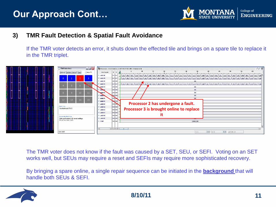
3) TMR Fault Detection & Spatial Fault Avoidance
If the TMR voter detects an error, it shuts down the effected tile and brings on a spare tile to replace it
in the TMR triplet.
The TMR voter does not know if the fault was caused by a SET, SEU, or SEFI. Voting on an SET
works well, but SEUs may require a reset and SEFIs may require more sophisticated recovery.
By bringing a spare online, a single repair sequence can be initiated in the background that will
handle both SEUs & SEFI.
Processor 2 has undergone a fault. Processor 3 is brought online to replace
it

8/10/11 12
Our Approach Cont…
4) Background Repair via Partial Reconfiguration
In the background, a recovery sequence is run that will perform partial reconfiguration on
the damaged tile.
This handles a potential SEFIs in addition to a SEUs in the circuit fabric.
The tile is then introduced in the system as an available spare.
ICAP address x00018280 corresponds to partial
reconfiguration of Tile 0
Active processors continue to run while PR occurs in background
GUI indicates processor 0 has been
repaired and is available as a spare
8/10/11 13
Our Approach Cont…
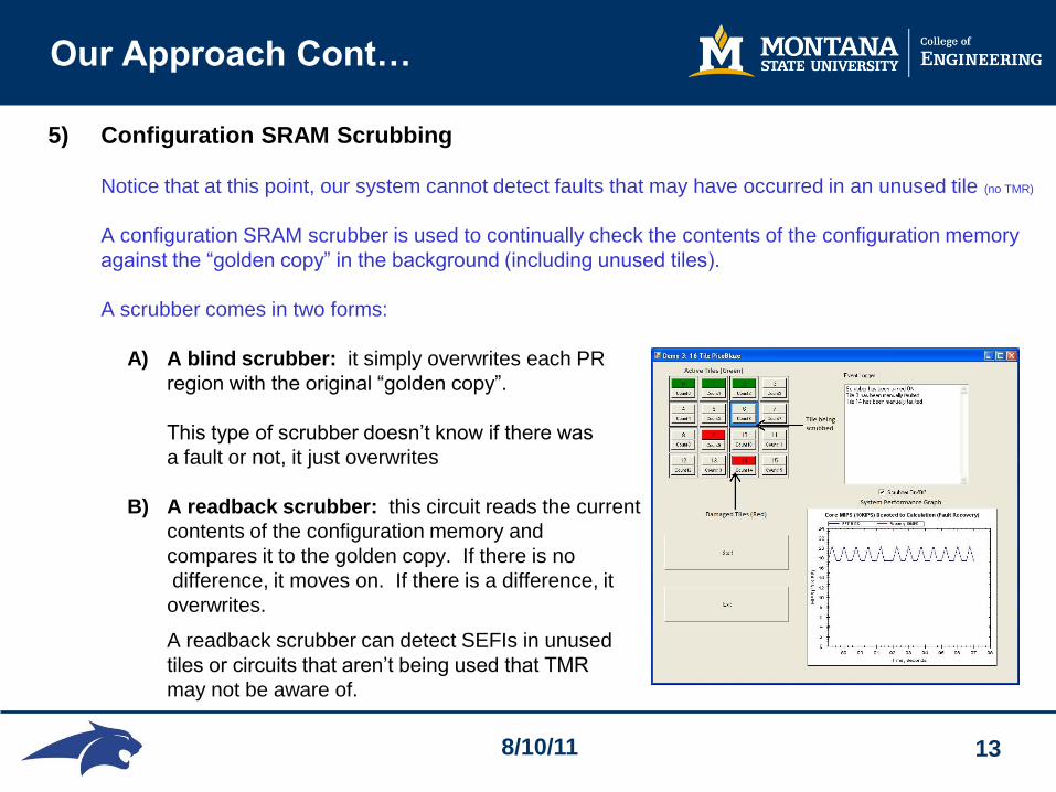
5) Configuration SRAM Scrubbing
Notice that at this point, our system cannot detect faults that may have occurred in an unused tile (no TMR)
A configuration SRAM scrubber is used to continually check the contents of the configuration memory
against the “golden copy” in the background (including unused tiles).
A scrubber comes in two forms:
A) A blind scrubber: it simply overwrites each PR
region with the original “golden copy”.
This type of scrubber doesn’t know if there was
a fault or not, it just overwrites
B) A readback scrubber: this circuit reads the current
contents of the configuration memory and
compares it to the golden copy. If there is no
difference, it moves on. If there is a difference, it
overwrites.
A readback scrubber can detect SEFIs in unused
tiles or circuits that aren’t being used that TMR
may not be aware of.

8/10/11 14
Our Approach Cont…
6) Integration with a Spatial Radiation Sensor
At this point, the scrubber is moving through the configuration memory in a sequential manner.
But what happens if a SEFI occurs in a region that the scrubber just checked? Or in a region that
won’t be checked for a while? This can lead to latency between detect & repair
If the system knew the location of potential faults, it could repair these tiles first instead of the tile
waiting for its turn. This gives us an environmentally aware scrubber
A spatial radiation sensor is integrated with the many-tile system in order to provide XY locations of
potential radiation strikes. This information is used to avoid & repair potential faults before they cause
a circuit failure.

8/10/11 15
Advantages of Our Approach
Detection, Avoidance and Repair
- The avoidance and background repair of faults recovers from SETs, SEUs, and SEFIs.
- The repair occurs in the background which minimizes the impact on the foreground computation.
Environmental Awareness
- The environmentally aware sensor/scrubber pair minimizes the latency between detection and
repair of faults
- The environment awareness provided by the sensor can repair SEUs in unused circuitry (both in
active and spare tiles) before they cause a fault condition. This further increases foreground
efficiency.
A Fault Tolerant Layer to Build Upon
- We are prototyping using homogenous tiles, they could be arbitrary circuits for RC.
- We don’t use spare tiles, but they could be used for increased computation.
- We use TMR, but other low overhead strategies could be used.

8/10/11 16
Status Of Our Many-Tile System
We have implemented a variety of Many-Tile systems on a Xilinx Virtex-6
64-Tile Counter
System
36-Tile picoBlaze
System running
Software FFT
16-Tile picoBlaze System
performing FFT with
HW accelerator
16-Tile MicroBlaze
System

8/10/11 17
Status Of Our Many-Tile System
We have developed a new status GUI that communication with FPGA via USB
We have implemented scrubbers for all of our Many-Tile systems for the V6
-Both Blind and Readback scrubber implemented on all many-tile systems.
- All scrubbers have ability to run in “sequential” or “environment aware” mode.

8/10/11 18
Status Of Our Many-Tile System
All many-tile systems have been integrated with the with our radiation sensor

8/10/11 19
Status of Radiation Sensor
We have fabricated a 256 pixel, XY radiation sensor
- designed for use with high energy particles (heavy ions, high energy protons)
- 20mm x 20mm size is large enough to cover all modern FPGA die sizes
A custom package PCB is used to hold the sensor

8/10/11 20
Sensor Operation
P
P P PN N N N
Metal Contact
Metal Contact
Particle Track
Intrinsic
Silicon
Barrier Diffusions
Electrons
Holes
Cross Section of Sensor
- 16 topside &16 bottom side contact strips running perpendicular to each other gives 256 XY locations.
- Particles passing through generate electron/hole pairs.
- Biasing causes the elections & holes to flow to either the topside or bottom side contacts for detection.

8/10/11 21
Sensor Fabrication (Full Wafer)
The sensor was created at the Montana Microfabrication Facility
8/10/11 22
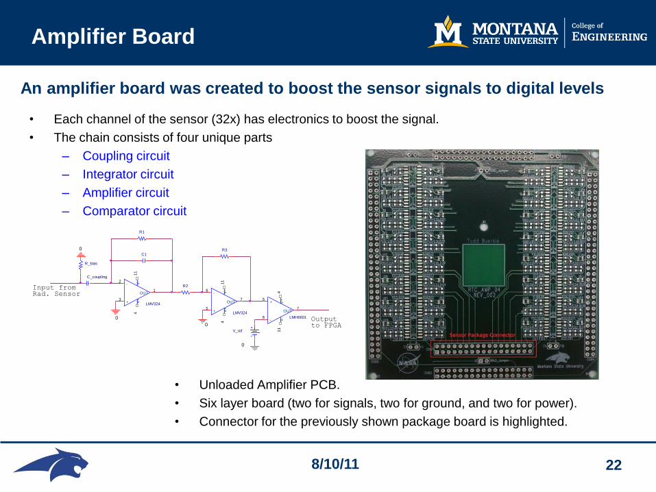
Amplifier Board
• Unloaded Amplifier PCB.
• Six layer board (two for signals, two for ground, and two for power).
• Connector for the previously shown package board is highlighted.
Outputto FPGA
LMV3243
2
411
1
+
-
V+
V-
OUT
R1
C_coupling
Input fromRad. Sensor
0C1
R_bias
V_ref
0
R3
LMV3245
6
411
7
+
-
V+
V-
OUT
LMH6601
5
6
411
7
+
-
V+
V-
OUT
0
R2
0
• Each channel of the sensor (32x) has electronics to boost the signal.
• The chain consists of four unique parts
– Coupling circuit
– Integrator circuit
– Amplifier circuit
– Comparator circuit
An amplifier board was created to boost the sensor signals to digital levels

8/10/11 23
Radiation Sensor System
The entire sensor system is designed to be stackable
- trajectory calculation
- integration with future custom FPGA board

8/10/11 24
High Altitude Testing of Sensor
The sensor was flown to 97,237 ft on 7/29/11

8/10/11 25
High Altitude Testing of Sensor
Data collected indicates increasing # of strikes at increased altitude

8/10/11 26
Demonstrations