ms_uc / dnd / v08 3- 1 rtc - real time clock programming microcontroller rtc – real time clock...
Post on 21-Dec-2015
237 views
TRANSCRIPT
3- 1
RTC - Real Time Clock
MS_uC / dnd / V08
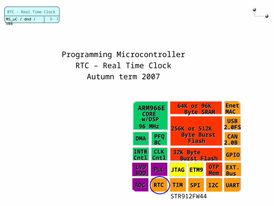
Programming MicrocontrollerRTC – Real Time Clock
Autumn term 2007
32K Byte 32K Byte Burst FlashBurst Flash
64K or 96K 64K or 96K Byte SRAM Byte SRAM
256K or 512K 256K or 512K Byte Burst Byte Burst
FlashFlash
OTP OTP MemMem
UARTUARTI2CI2CSPISPITIMTIMRTCRTC
EXT. EXT. Bus Bus
GPIOGPIO
USB USB 2.0FS 2.0FS
CAN CAN 2.0B 2.0B
Enet Enet MAC MAC
PFPFQ Q
BC BC
DMADMA
INTINTR R
CntlCntl
ARM96ARM966E 6E CORE CORE
w/DSPw/DSP96 MHz 96 MHz
CLK CLK CntlCntl
ADCADC
LVD LVD BODBOD
PLLPLL JTAJTAGG
ETMETM99
STR912FW44

3- 2
RTC - Real Time Clock
MS_uC / dnd / V08
RTC Specifics
Self-isolation Mode RTC continues to operate
After power down Supply voltage drops out
Automatically switches to alternate voltage source connected to VBATT pin (e.g.battery)
Isolated 32KHz osc. continues to operate
Tamper Detect (Manipulation) RTC time recorded
SRAM standby voltage source cut off to invalidate SRAM contents
Millisecond counter, wake-up function
Real Time ClockComplete Time of Day Clock
Time is in 24 hour modeBCD format
Millisecond resolution9999 year calendar (leap year support)
Programmable Alarm (1 month)Periodic Interrupt Generation
(1 – 512Hz)Tamper Detection
Clock Calibration Output
3- 3
RTC - Real Time Clock
MS_uC / dnd / V08
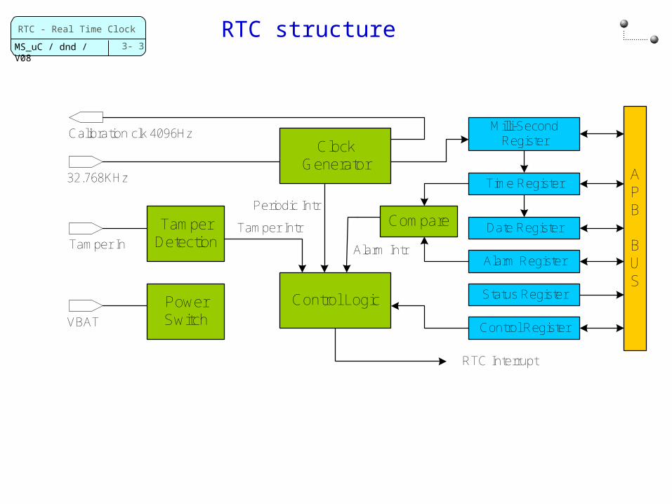
RTC structure
Clock Generator
Time Register
Date Register
Alarm Register
Status Register
APB
BUS
Control Register
Power Switch
32.768KHz
Calibration clk 4096HzMilli-Second
Register
TamperDetection
VBAT
Tamper In
Control Logic
CompareTamper Intr
Periodic Intr
Alarm Intr
RTC Interrupt

3- 4
RTC - Real Time Clock
MS_uC / dnd / V08
RTC Block diagram (simplified)
Ref manual figure 26
3- 5
RTC - Real Time Clock
MS_uC / dnd / V08
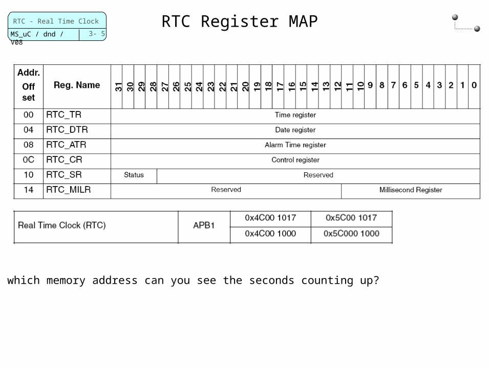
RTC Register MAP
? On which memory address can you see the seconds counting up?
3- 6
RTC - Real Time Clock
MS_uC / dnd / V08
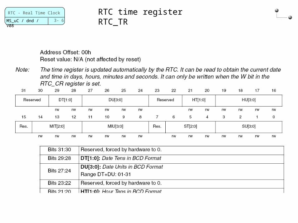
RTC time registerRTC_TR
3- 7
RTC - Real Time Clock
MS_uC / dnd / V08
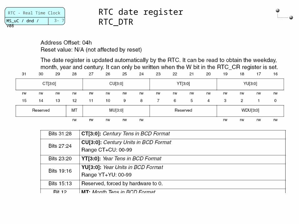
RTC date registerRTC_DTR
3- 8
RTC - Real Time Clock
MS_uC / dnd / V08
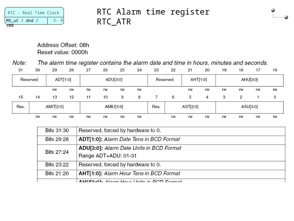
RTC Alarm time registerRTC_ATR
3- 9
RTC - Real Time Clock
MS_uC / dnd / V08
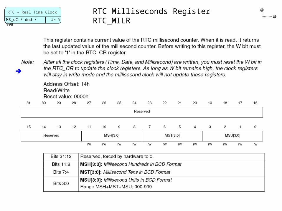
RTC Milliseconds RegisterRTC_MILR
3- 10
RTC - Real Time Clock
MS_uC / dnd / V08
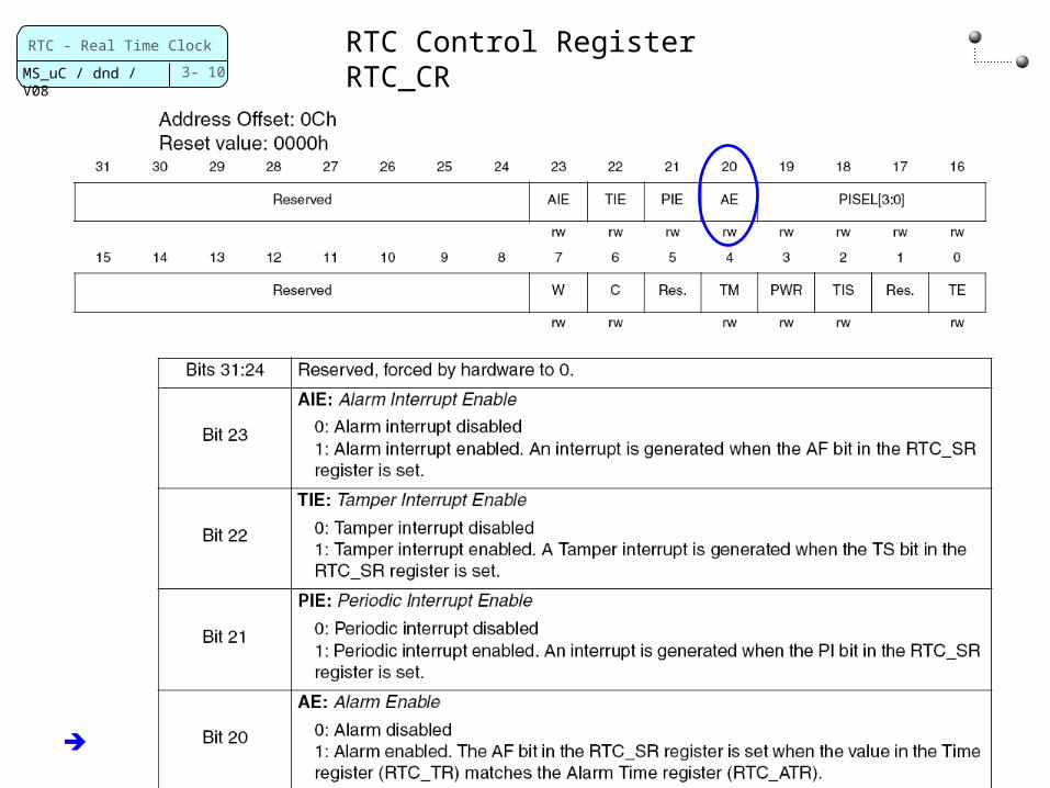
RTC Control RegisterRTC_CR
3- 11
RTC - Real Time Clock
MS_uC / dnd / V08
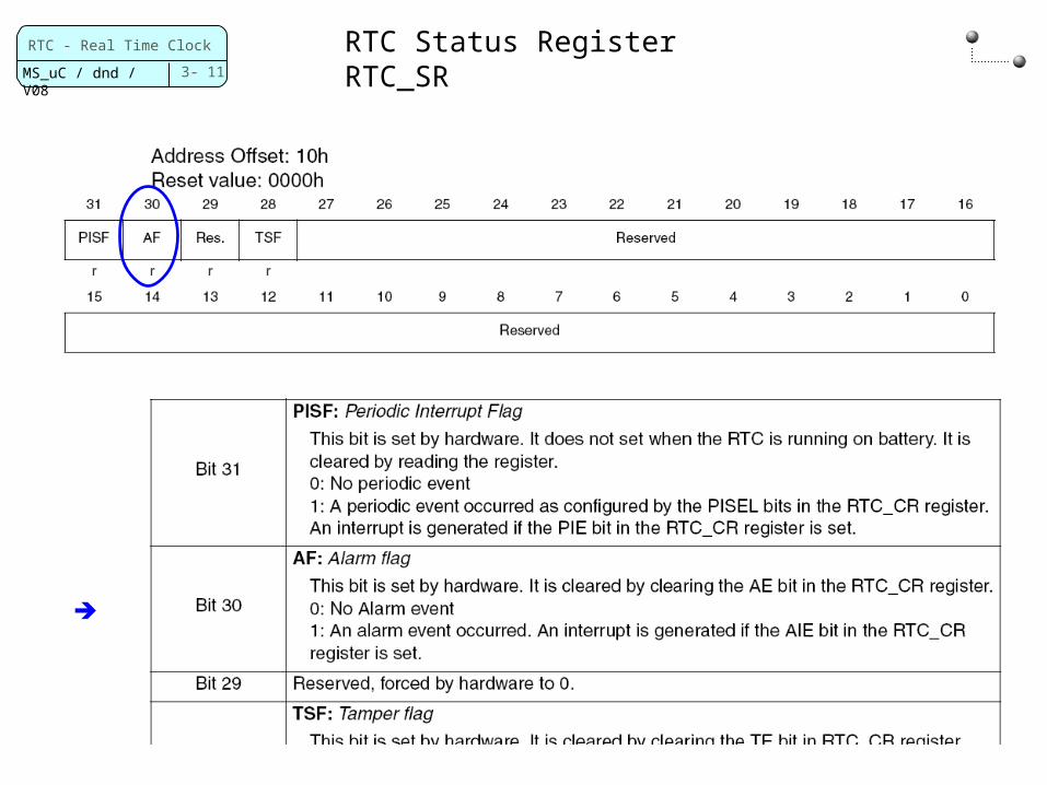
RTC Status RegisterRTC_SR
3- 12
RTC - Real Time Clock
MS_uC / dnd / V08
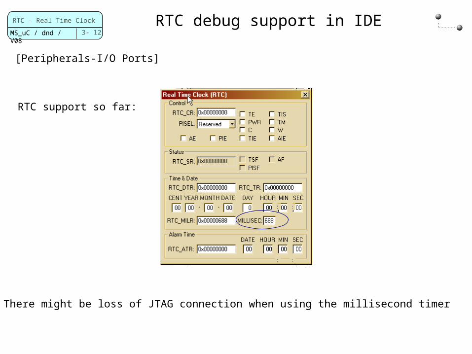
RTC debug support in IDE
[Peripherals-I/O Ports]
RTC support so far:
=> There might be loss of JTAG connection when using the millisecond timer
3- 13
RTC - Real Time Clock
MS_uC / dnd / V08
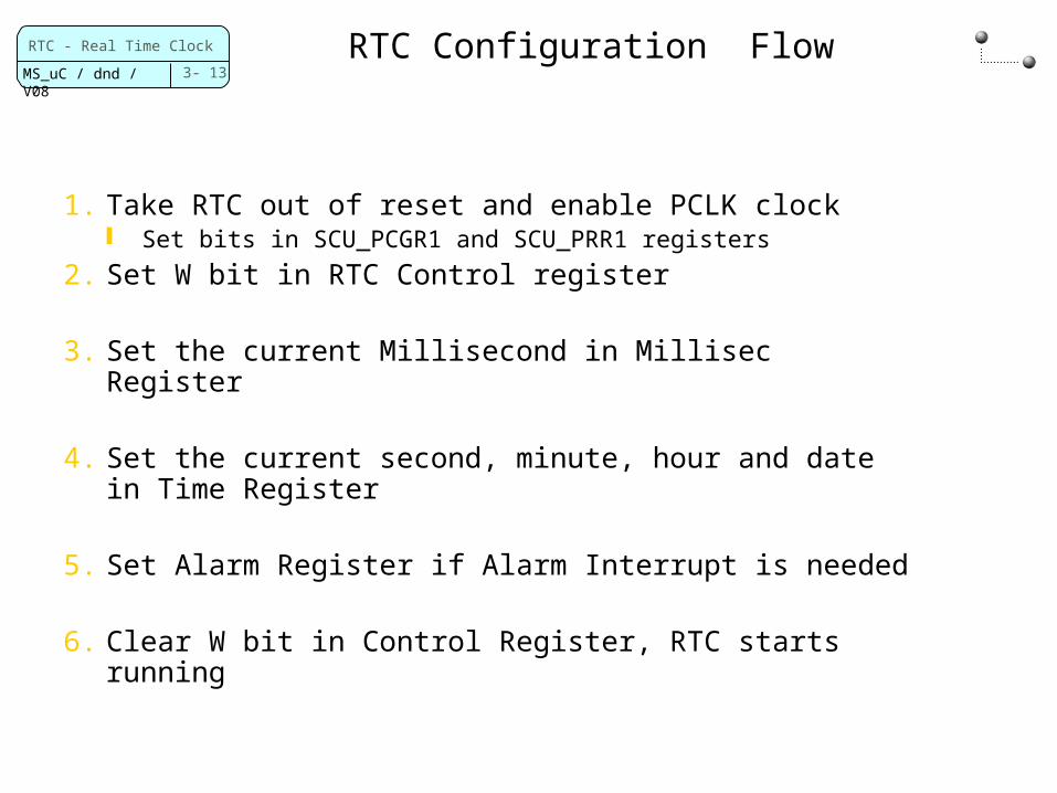
RTC Configuration Flow
1. Take RTC out of reset and enable PCLK clock Set bits in SCU_PCGR1 and SCU_PRR1 registers
2. Set W bit in RTC Control register
3. Set the current Millisecond in Millisec Register
4. Set the current second, minute, hour and date in Time Register
5. Set Alarm Register if Alarm Interrupt is needed
6. Clear W bit in Control Register, RTC starts running
3- 14
RTC - Real Time Clock
MS_uC / dnd / V08
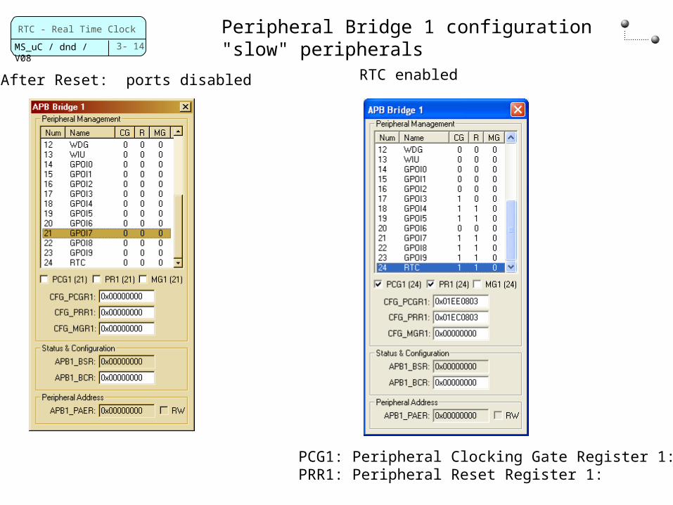
Peripheral Bridge 1 configuration"slow" peripherals
PCG1: Peripheral Clocking Gate Register 1: PRR1: Peripheral Reset Register 1:
RTC enabledAfter Reset: ports disabled

3- 15
RTC - Real Time Clock
MS_uC / dnd / V08
Watchdog (WDG)
What is a watch dog in a microcontroller?
A device that supervises correct functioning of the controller
What can watch dog do?
Just bark and say: "We ar not ok" or reset the controller
3- 16
RTC - Real Time Clock
MS_uC / dnd / V08
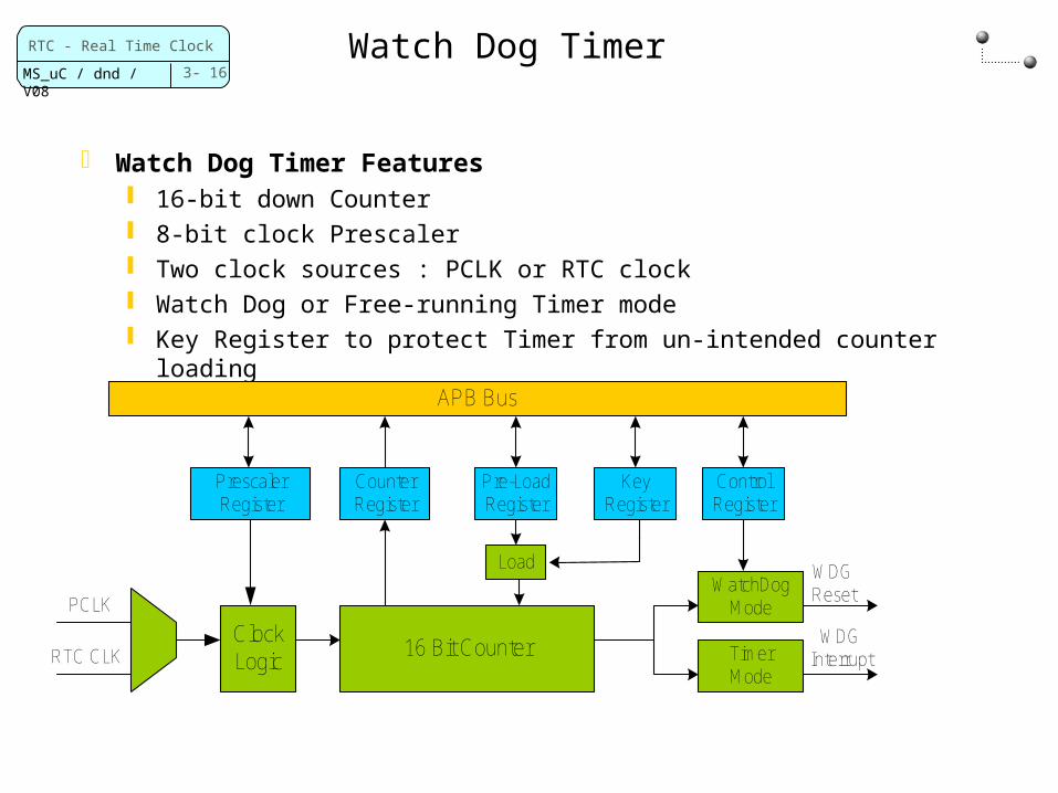
Watch Dog Timer
Watch Dog Timer Features 16-bit down Counter 8-bit clock Prescaler Two clock sources : PCLK or RTC clock Watch Dog or Free-running Timer mode Key Register to protect Timer from un-intended counter loading
PrescalerRegister
CounterRegister
KeyRegister
APB Bus
Pre-LoadRegister
ClockLogic
PCLK
RTC CLK
Load
16 Bit Counter
ControlRegister
WatchDogMode
TimerMode
WDGReset
WDGInterrupt

3- 17
RTC - Real Time Clock
MS_uC / dnd / V08
Watch Dog Timer Modes
Watch Dog Mode Once enabled, this mode cannot be cleared by software Generates Reset when the 16 bit down counter reaches 0 count Prevent WDG_reset by writing twice (A55A, 5AA5) to the Key
Register. Counter is re-loaded after the write
WDG Free running Timer Mode User can pre-load counter and control the counting start
Can read counter values from Counter Register Generate interrupt when down counter reaches end of count Interrupt can be disabled, end of count flag is set in Status
Register